


 Loading...
JUMO dTRON 304/308/316
Compact Controller with program function
Type 703043
|
|
|
|
|
|
|
|
|
|
Type 703041 |
|
Type 703042 |
Type 703044 |
|
B 70.3041.0
Operating Manual
2010-04-30/00442056
)Please read this operating manual before commissioning the instrument. Keep the manual in a place which is accessible to all users at all times.
Your comments are appreciated and may help us in improving this manual.
All necessary settings are described in this operating manual. Manipulations not described in the manual or expressly forbidden will jeopardize your warranty rights. Please contact the nearest subsidiary or the head office, should you encounter problems.
This manual is valid from instrument software version 192.02.05. It appears by simultaneously pressing the  and
and  keys.
keys.
When accessing the inner parts of the unit and returning modules, assemblies or components, Eplease observe the regulations accordings to EN 61340-5-1 and EN 61340-5-2 „Protection of elec-
trostatic sensitive devices“. Only use ESD packaging for transport.
Please note that we cannot accept any liability for damage caused by ESD.
ESD=Electro Static Discharge

|
|
Contents |
1 |
Introduction |
7 |
1.1 |
Description .................................................................................................... |
7 |
1.2 |
Typographical conventions ......................................................................... |
8 |
2 |
Identifying the instrument version |
9 |
2.1 |
Type designation .......................................................................................... |
9 |
2.2 |
Scope of delivery ........................................................................................ |
10 |
2.3 |
Accessories ................................................................................................ |
10 |
3 |
Mounting |
11 |
3.1 |
Mounting site and climatic conditions ..................................................... |
11 |
3.2 |
Dimensions ................................................................................................. |
11 |
3.2.1 |
Type 703044 ................................................................................................. |
11 |
3.2.2 |
Type 703042/43 ............................................................................................ |
12 |
3.2.3 |
Type 703041 ................................................................................................ |
12 |
3.3 |
Side-by-side mounting .............................................................................. |
13 |
3.4 |
Fitting in position ........................................................................................ |
13 |
3.5 |
Removing the controller module .............................................................. |
14 |
4 |
Electrical connection |
15 |
4.1 |
Installation notes ........................................................................................ |
15 |
4.2 |
Electrical isolation ...................................................................................... |
16 |
4.3 |
Connection diagrams ................................................................................. |
17 |
4.3.1 |
Type 703041 ................................................................................................. |
17 |
4.3.2 |
Type 703042/43/44 ...................................................................................... |
20 |
4.3.3 |
Termination resistor for the RS422/485 serial interface ............................... |
24 |
4.3.4 |
Connection of the PROFIBUS-DP connector .............................................. |
24 |

|
|
Contents |
5 |
Operation |
25 |
5.1 |
Displays and controls ................................................................................ |
25 |
5.2 |
Level concept ............................................................................................. |
26 |
5.3 |
Level inhibit ................................................................................................. |
27 |
5.4 |
Entries and operator prompting ............................................................... |
28 |
5.5 |
Fixed-setpoint controller (ex-factory) ....................................................... |
29 |
5.6 |
Program controller ..................................................................................... |
30 |
5.6.1 |
Entering programs ........................................................................................ |
30 |
5.6.2 |
Operation ..................................................................................................... |
32 |
5.6.3 |
Shifting the program profile .......................................................................... |
33 |
6 |
Operator level |
35 |
7 |
Parameter level |
37 |
8 |
Configuration |
39 |
8.1 |
Analog inputs “InP” .................................................................................... |
41 |
8.1.1 |
Customized fine tuning ................................................................................ |
43 |
8.2 |
Controller “Cntr” ........................................................................................ |
45 |
8.3 |
Generator “Pro” .......................................................................................... |
47 |
8.4 |
Limit comparators “LC” ............................................................................. |
50 |
8.5 |
Outputs “OutP” ........................................................................................... |
54 |
8.6 |
Binary functions “binF” .............................................................................. |
56 |
8.7 |
Display “diSP” ............................................................................................. |
59 |
8.8 |
Timer “tFct” ................................................................................................ |
61 |
8.9 |
Interfaces “IntF” ......................................................................................... |
62 |
9 |
Tuning (optimization) |
63 |
9.1 |
Autotuning (self-optimization) ................................................................... |
63 |
9.2 |
Check of the tuning .................................................................................... |
66 |

|
|
Contents |
10 |
Extra codes |
67 |
10.1 |
Math and logic module .............................................................................. |
67 |
10.2 |
Difference, humidity or ratio controller .................................................... |
67 |
11 |
Retrofitting of modules |
69 |
12 |
Appendix |
71 |
12.1 |
Technical data ............................................................................................. |
71 |
12.2 |
Alarm messages ......................................................................................... |
74 |
13 |
Index |
75 |

Contents
1 Introduction
1.1 Description
The controller series consists of four freely programmable instruments in different DIN formats for controlling temperature, pressure and other process variables.
As a temperature controller TR1 according to EN 14597 the devices are used in heatgenerating plants to control the temperature of liquids or gases (mode of action: 1B).
The high-contrast, multicolor LCD display for process value, setpoint and operator prompting contains two four-digit 7-segment displays, two single-character 16segment displays, display of the active setpoints, six status indicators, and displays for the unit, ramp function and manual operation.
Just four keys on the front panel are needed for operation, parameterization and configuration. The instruments can be used as 2-state, 3-state, modulating or continuous controllers. The controller software includes a program or ramp function, parameter set changeover, two autotuning (self-optimization) procedures, a math and logic module, as well as 4 limit comparators.
Linearizations for the usual transducers are stored, and a customer-specific linearization table can be programmed.
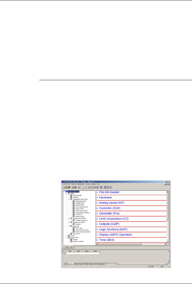
A setup program is available for user-friendly configuration from a PC.
An RS422/485 or a Profibus-DP interface can be used to integrate the instrument into a data network.
The electrical connection is made at the back of the instrument, via screw terminals.
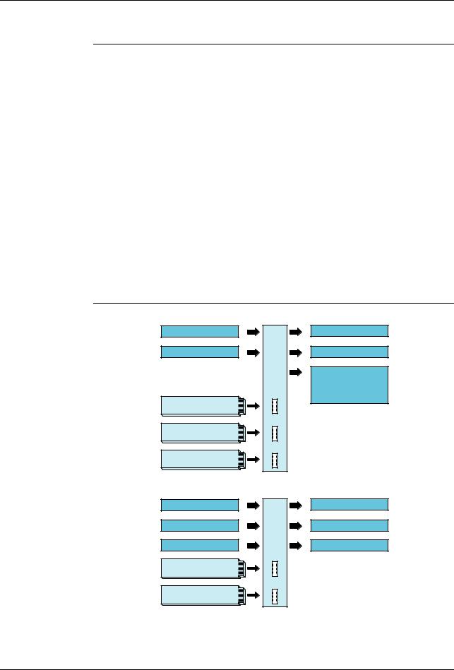
Analog input
2 binary inputs
Option 1
Option 2
Option 3
Type 703042/43/44
2 relays (changeover)
2 logic outputs
Supply voltage 17 V / 20 mA for 2-wire transmitter
|
Type 703041 (48mm x 48mm) |
|
Analog input |
|
2 relays (make) |
Binary input |
or |
Logic output |
Binary input |
or |
Logic output |
Option 1 |
|
|
Option 2 |
|
|
1. For more detailed explanation, see EN 14597
7

1 Introduction
1.2 Typographical conventions
Warning signs |
VDanger |
* Caution
ECaution
Note signs |
H Note |
|
v Reference |
This symbol is used when there may be danger to personnel if the instructions are ignored or not followed correctly!
This symbol is used when there may be damage to equipment or data if the instructions are ignored or not followed correctly!
This symbol is used where special care is required when handling components liable to damage through electrostatic discharge.
This symbol is used when your special attention is drawn to a remark.
This symbol refers to further information in other operating instructions, chapters or sections.
HAction This symbol indicates that an action to be performed is instruction described.
The individual steps are marked by this asterisk, e.g. h Press X
Representation |
Menu items |
Blinking display
Texts from the setup program are shown in italics, for example: edit program.
I |
I I I I I I I I I I I I I I I |
I |
||
I |
|
|
I |
|
| <![if ! IE]> <![endif]>I I I |
|
|
|
<![if ! IE]> <![endif]>I I I |
I |
|
|
I |
I |
I |
I I I I I I I I I I I I I I |
|
||
8
2 Identifying the instrument version
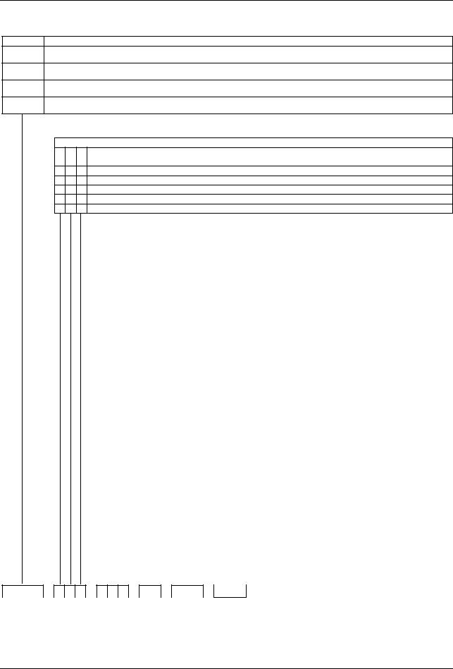
2.1 Type designation
Basic type
703041 JUMO dTRON 316, format 48mm x 48mm
incl. 1 analog input, 2 relay outputs and 2 binary inputs or 2 logic outputs
703042 JUMO dTRON 308, format 48mm x 96mm (portrait format) incl. 1 analog and 2 binary inputs, 2 relays and 2 logic outputs
703043 JUMO dTRON 308, format 96mm x 48mm (landscape format) incl. 1 analog and 2 binary inputs, 2 relays and 2 logic outputs
703044 JUMO dTRON 304, format 96mm x 96mm
incl. 1 analog and 2 binary inputs, 2 relays and 2 logic outputs
Basic type extensions
1 |
Basic type 1 |
|
Version |
8standard, with factory settings
9programming to customer specification
logic outputs (2 are available as standard)
10 / 12V
20 / 18V
|
|
|
|
|
|
|
|
|
|
|
|
|
|
|
|
|
|
|
Type 703042/43/44 |
|
Type 703041 (no option 3) |
||
1. |
2. |
3. |
Option slot |
|
|
|
|
|
|
|
|
Max. number |
|
Max. number |
Option 1 |
Option 2 |
|||||||
|
|
|
|
|
|
|
|
|
|
|
|
|
|
|
|
|
|
|
|
|
|
|
|
0 |
0 |
0 |
not used |
|
|
|
|
|
|
|
|
|
|
|
|
|
X |
X |
|||||
|
|
|
|
|
|
|
|
|
|
|
|
|
|
|
|
|
|
|
|
|
|
||
1 |
1 |
1 |
analog input 2 (universal) |
|
|
1 |
|
1 |
X |
X |
|||||||||||||
|
|
|
|
|
|
|
|
|
|
|
|
|
|
|
|
|
|
|
|
|
|
|
|
2 |
2 |
2 |
relay (changeover) |
|
|
|
|
|
|
2 |
|
1 |
X |
- |
|||||||||
|
|
|
|
|
|
|
|
|
|
|
|
|
|
|
|
|
|
|
|
|
|
||
3 |
3 |
3 |
2 relays (make contact) |
|
|
|
|
|
2 |
|
1 |
X |
- |
||||||||||
|
|
|
|
|
|
|
|
|
|
|
|
|
|
|
|
|
|
|
|
|
|
|
|
4 |
4 |
4 |
analog output |
|
|
|
|
|
|
|
|
2 |
|
2 |
X |
X |
|||||||
|
|
|
|
|
|
|
|
|
|
|
|
|
|
|
|
|
|
|
|
|
|
|
|
5 |
5 |
5 |
2 binary inputs |
|
|
|
|
|
|
|
|
2 |
|
1 |
X |
X |
|||||||
|
|
|
|
|
|
|
|
|
|
|
|
|
|
|
|
|
|
|
|
|
|
|
|
6 |
6 |
6 |
solid-state relay 1A |
|
|
|
|
|
|
2 |
|
2 |
X |
X |
|||||||||
|
|
|
|
|
|
|
|
|
|
|
|
|
|
|
|
|
|
|
|
|
|
|
|
7 |
7 |
7 |
RS422/485 interface |
|
|
|
|
|
|
1 |
|
1 |
X |
X |
|||||||||
|
|
|
|
|
|
|
|
|
|
|
|
|
|
|
|
|
|
|
|
|
|
||
8 |
8 |
8 |
Profibus-DP interface |
|
|
|
|
|
1 |
|
1 |
X |
X |
||||||||||
|
|
|
|
|
|
|
|
|
|
|
|
|
|
|
|
|
|
|
|
|
|||
|
|
|
|
|
|
X = available in this option slot, - = not available in this option slot |
|
|
|
||||||||||||||
|
|
|
|
|
|
|
|
|
|
|
|
|
|
|
|
|
|
|
|
|
|
|
|
|
|
|
|
|
|
|
|
|
Supply |
|
|
|
|
|
|
|
|
|
|
|
|||
|
|
|
|
|
|
|
|
|
|
|
|
|
|
|
|
|
|
|
|
||||
|
|
|
|
|
|
|
2 |
3 |
110 — 240V AC -15/+10%, 48 — 63Hz |
|
|
|
|||||||||||
|
|
|
|
|
|
|
|
|
|
|
|
|
|
|
|
|
|
|
|
||||
|
|
|
|
|
|
|
2 |
5 |
20 — 30V AC/DC, 48 — 63Hz |
|
|
|
|||||||||||
|
|
|
|
|
|
|
|
|
|
|
|
|
|
|
|
|
|
|
|
|
|
|
|
|
|
|
|
|
|
|
|
|
|
|
|
|
|
|
|
|
|
|
|
|
|||
|
|
|
|
|
|
|
|
|
|
|
|
|
|
Extra codes |
|
|
|
|
|
||||
|
|
|
|
|
|
|
|
|
|
|
|
|
|
|
|
|
|
|
|
|
|
|
|
|
|
|
|
|
|
|
|
|
|
0 |
0 |
|
0 |
none |
|
|
|
|
|
|
|
||
|
|
|
|
|
|
|
|
|
|
|
|
|
|
|
|
|
|
|
|
||||
|
|
|
|
|
|
|
|
|
|
2 |
1 |
|
4 |
math and logic module |
|
|
|
||||||
|
|
|
|
|
|
|
|
|
|
|
|
|
|
|
|
|
|
|
|||||
|
|
|
|
|
|
|
|
|
|
2 |
1 |
|
7 |
ratio controller (requirement: 2 analog inputs) |
|
|
|||||||
|
|
|
|
|
|
|
|
|
|
|
|
|
|
|
|
|
|
|
|||||
|
|
|
|
|
|
|
|
|
|
2 |
1 |
|
8 |
difference controller (requirement: 2 analog inputs) |
|
|
|||||||
|
|
|
|
|
|
|
|
|
|
|
|
|
|
|
|
|
|
|
|||||
|
|
|
|
|
|
|
|
|
|
2 |
1 |
|
9 |
humidity controller (requirement: 2 analog inputs) |
|
|
|||||||
|
|
|
|
|
|
|
|
|
|
|
|
|
|
|
|
|
|
|
|
|
|
|
|
|
|
|
|
|
|
|
|
|
|
|
|
|
|
|
|
|
|
|
Approvals |
|
|
|
|
|
|
|
|
|
|
|
|
|
|
|
|
|
|
|
|
|
|
|
|
|
|
||
|
|
|
|
|
|
|
|
|
|
|
|
|
|
|
|
0 |
0 |
0 |
none |
|
|
|
|
|
|
|
|
|
|
|
|
|
|
|
|
|
|
|
|
|
|
|
|
|
|
||
|
|
|
|
|
|
|
|
|
|
|
|
|
|
|
|
0 |
5 |
6 |
DIN EN 14597 |
|
|
|
|
|
|
|
|
|
|
|
|
|
|
|
|
|
|
|
|
|
|
|
|
|
|
||
|
|
|
|
|
|
|
|
|
|
|
|
|
|
|
|
|
|
|
dTRON 304 with GL approval |
|
on request |
||
|
|
|
|
|
|
|
|
|
|
|
|
|
|
|
|
|
|
|
|
|
|
|
|
|
|
|
|
|
|
|
|
|
|
|
|
|
|
|
|
|
|
|
|
|
|
|
|
|
/ |
1 |
|
– |
|
– |
|
/ |
|
, |
703041 |
/ |
1 |
8 1 |
– |
1 4 0 – |
2 3 |
/ |
0 0 0 |
, |
|
9
2 Identifying the instrument version
2.2Scope of delivery
-1 controller
-1 seal
-mounting brackets
-Operating Manual B70.3041.0 in DIN A6 format
1 CD with demo software and PDF documents in DIN A4 format (operating manual and further documentation) can be ordered separately.
The individual documents and programs are available for dowload from www.jumo.net (the software can be enabled for a charge.)
2.3 Accessories
PC interface |
PC interface with TTL/RS232 converter and adapter (socket connector) for setup |
|
program |
|
Sales No. 70/00350260 |
USB interface |
|
PC interface with USB/TTL converter, adapter (socket conector) and adapter (pins) |
|
|
Sales No. 70/00456352 |
Setup |
|
Setup program with program editor and Startup |
|
program |
Sales No. 70/00445443 |
|
Hardware requirements: |
|
- PC Pentium 100 or compatible |
|
- 128 MB RAM, 30 MB free fixed disc memory |
|
- CD ROM drive |
|
- free serial or USB interface |
|
Software requirements: |
|
Microsoft1 Windows 98/NT4.0/ME/2000/XP |
1. Microsoft is a registered trademark of Microsoft Corporation
10
3 Mounting
3.1 Mounting site and climatic conditions
The conditions on the mounting site must meet the requirements specified in the technical data. The ambient temperature on the mounting site can be from 0 to 55 °C, with a relative humidity of not more than 90 %.
3.2 Dimensions
3.2.1 Type 703044 |
Setup plug
Panel cut-out
11

3 Mounting
3.2.2 Type 703042/43
<![if ! IE]><![endif]>Setup plug
Panel cut-out
3.2.3 Type 703041
Setup plug
Panel cut-out
12
3 Mounting
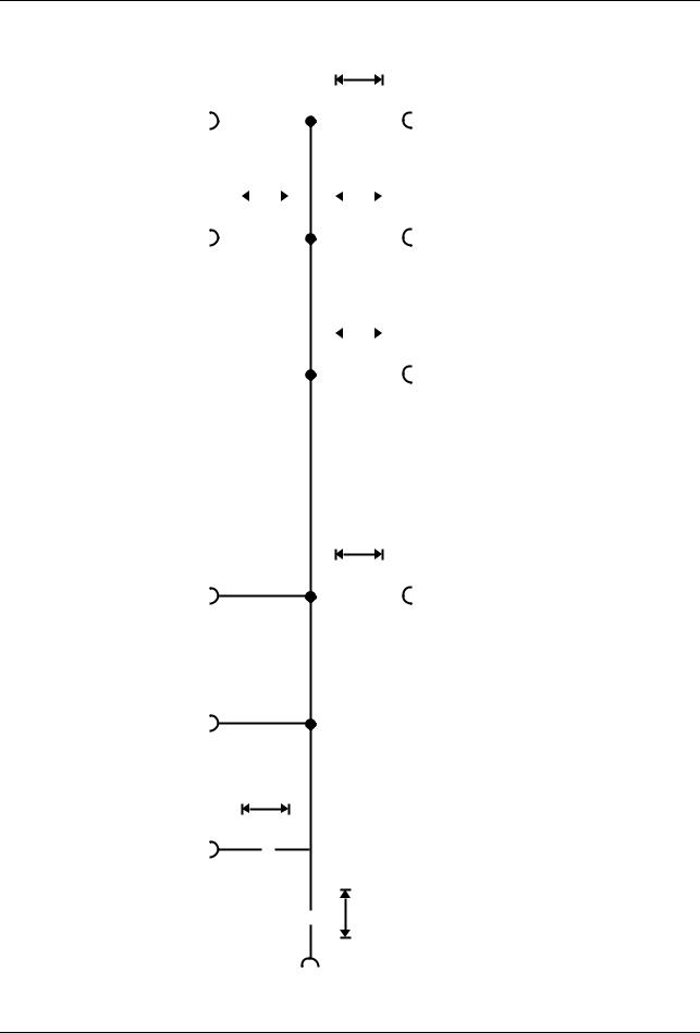
3.3 Side-by-side mounting
|
Minimum spacing of panel cut-outs |
|
|
||
Type |
|
|
horizontal |
|
vertical |
|
|
|
|||
|
|
|
|
|
|
without setup plug: |
|
|
|
|
|
703041 |
(48mm x 48mm) |
|
11mm |
|
30mm |
|
|
||||
703042 |
(portrait format: 48mm x 96mm)) |
|
11mm |
|
30mm |
703043 |
(landscape format: 96mm x 48mm) |
|
30mm |
|
11mm |
703044 |
(96mm x 96mm) |
|
11mm |
|
30mm |
|
|
|
|
|
|
with setup plug (see arrow): |
|
|
|
|
|
703041 |
(48mm x 48mm) |
|
11mm |
|
65mm |
|
|
||||
703042 |
(portrait format: 48mm x 96mm)) |
|
11mm |
|
65mm |
703043 |
(landscape format: 96mm x 48mm) |
|
65mm |
|
11mm |
703044 |
(96mm x 96mm) |
|
11mm |
|
65mm |
|
|
|
|
|
|
3.4 Fitting in position
Type 703042/43/44 h Fit the seal that is supplied onto the instrument body.
hInsert the controller from the front into the panel cut-out.
hFrom behind the panel, slide the mounting brackets into the guides on the sides of the housing.
The flat faces of the mounting brackets must lie against the housing.
hPush the mounting brackets up to the back of the panel, and tighten them evenly with a screwdriver.
Type 703041 |
h Fit the seal that is supplied onto the |
|
instrument body. |
|
h Insert the controller from the front into |
|
the panel cut-out. |
|
h From the back of the panel, push the |
|
mounting frame onto the instrument |
|
body and press it against the back of |
|
the panel, compressing the springs, |
|
until the latches snap into the notches |
|
provided and it is firmly fixed in position. |
Care of the front The front panel can be cleaned with normal commercial washing, rinsing and cleaning panel agents. It has a limited resistance to organic solvents (e.g. methylated spirits, white
spirit, P1, xylol etc.). Do not use high-pressure cleaning equipment.
13

3 Mounting
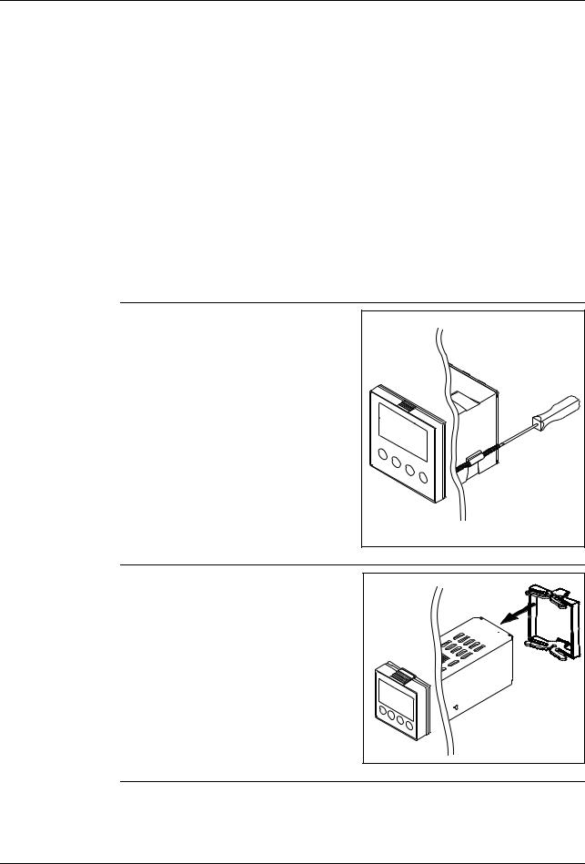
3.5 Removing the controller module
The controller module can be removed from its housing for servicing.
hPress together the knurled areas (top and bottom, or left and right for landscape format) and pull out the
controller module.
HWhen inserting the controller module, make sure that the latches (below the knurled areas) snap into place.
14

4 Electrical connection
4.1Installation notes
-The choice of cable, the installation and the electrical connection must conform to the requirements of VDE 0100 “Regulations on the Installation of Power Circuits with Nominal Voltages below 1000 V” or the appropriate local regulations.
-The electrical connection must only be carried out by qualified personnel.
-The instrument shall be operated by mains protected with a branch circuitry overcurrent protection device not more than 20 Amps.
For servicing/repairing a Disconnecting Device shall be provided to disconnect all conductors.
-The load circuit must be fused for the maximum relay current, in order to prevent the output relay contacts becoming welded in the event of a short circuit.
-Electromagnetic compatibility conforms to the standards and regulations cited in the technical data.
-Run input, output and supply cables separately and not parallel to one another.
-Sensor and interface cables should be shielded cables with twisted conductors. Do not run them close to current-carrying components or cables. Ground the shielding on one side.
-Do not connect any additional loads to the supply terminals of the instrument.
-The instrument is not suitable for use in areas with an explosion hazard (Ex areas).
-In addition to faulty installation, incorrect settings on the controller (setpoint, data of the parameter and configuration levels, internal alterations) can also interfere with the correct operation of dependent processes, or even cause damage. Safety devices should always be provided that are independent of the controller (such as overpressure valves or temperature limiters/monitors) and only capable of adjustment by specialist personnel. Please observe the relevant safety regulations for such matters. Since adaptation (self-optimization) can not be expected to handle all possible control loops, an unstable parameterization is theoretically possible. The stability of the actual value that is produced should therefore be checked.
.
V
H
The electrical connection must only be carried out by specialist personnel.
The instrument version can be identified by the type code.
Conductor cross-sections and core-end ferrules for installation
|
Minimum |
Maximum |
Min. length of |
|
cross-section |
cross-section |
core-end ferrule |
|
|
|
|
Without core-end ferrule |
0.34mm2 |
2.5mm2 |
10mm |
|
|
|
(stripped) |
|
|
|
|
Core-end ferrule, no lip |
0.25mm2 |
2.5mm2 |
10mm |
Core-end ferrule, lip up to 1.5mm2 |
0.25mm2 |
1.5mm2 |
10mm |
Core-end ferrule, lip above 1.5mm2 |
1.5mm2 |
2.5mm2 |
12mm |
Twin ferrule with lip |
0.25mm2 |
1.5mm2 |
12mm |
15
4 Electrical connection
4.2 Electrical isolation
3800 V AC
Input 1
Input 2
Binary inputs
Setup interface
RS422/485 PROFIBUS-DP
|
<![if ! IE]> <![endif]>» |
|
Relay outputs |
|||||||||||||
|
30 V AC |
|
|
|
||||||||||||
|
|
|||||||||||||||
|
50 V DC 3800 V AC |
|
||||||||||||||
|
|
|
|
|
|
|
|
|
|
|
|
|
||||
|
|
|
|
|
|
|
|
|
|
|
|
|
|
|
|
|
| <![if ! IE]> <![endif]>» » |
|
Solid-state relay outputs |
||||||||||||||
|
|
|
|
|
|
|
|
|
|
|
|
|
|
|
|
|
|
|
|
|
|
|
|
|
30 V AC |
||||||||
|
|
|
|
|
|
|
|
|
||||||||
|
|
|
|
|
|
|
|
50 V DC |
|
|||||||
|
|
|
|
|||||||||||||
|
|
|
|
|
|
|
|
|
|
|
|
|
|
|
|
|
|
|
|
|
|
|
|||||||||||
| <![if ! IE]> <![endif]>» |
|
Analog outputs |
||||||||||||||
|
|
|
|
|
|
|
|
|
|
|
|
|
|
|
|
|

 Logic outputs
30 V AC
50 V DC
| <![if ! IE]> <![endif]>» |
Supply voltage for |
||
|
|
|
|
|
|
|
2-wire transmitter |
30 V AC
50 V DC » 
» 3800 V AC
Supply voltage
16
1
1
2
3
4
5
6
7
8
<![if ! IE]><![endif]>17
2
1
2
3
4
6
7
8
3
L1(L+)
N(L-)
3
4
5
6
7
8
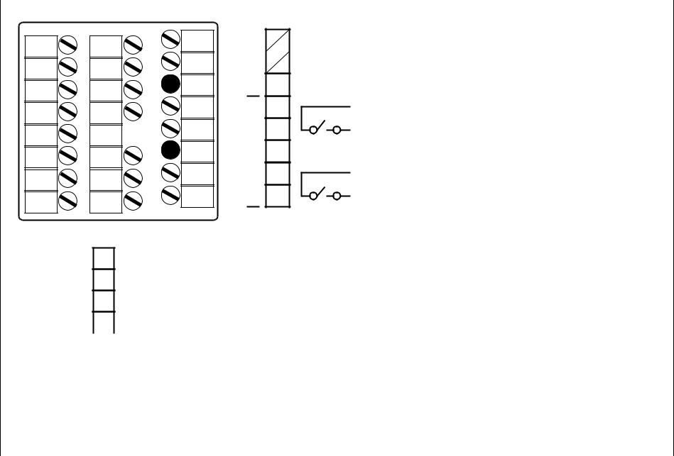
Supply and outputs - terminal strip 3
| <![if ! IE]> <![endif]>Supply |
|
L1 |
|
N |
|
L- |
|
|
|
|
L1 |
|
L+ |
||
|
|
L+ |
|
|
|
||
|
|
|
110—240V AC |
|
20—30V AC/DC |
||
|
|
N |
|
|
|||
|
|
L- |
|
|
|
|
|
|
3 |
|
|
4 |
P |
|
5 |
230V/3A Binary output 1 (Out1) |
| <![if ! IE]> <![endif]>Relays |
S |
|
6 |
|
|
|
|
|
|
7 |
P |
|
8 |
230V/3A Binary output 2 (Out2) |
|
S |
| <![if ! IE]> <![endif]>.3.4 |
<![if ! IE]> <![endif]>3.4 |
| <![if ! IE]> <![endif]>703041 Type 1 |
<![if ! IE]> <![endif]>Connection |
|
<![if ! IE]> <![endif]>diagrams |
Outputs - terminal strip 2
1
2
3
4
| <![if ! IE]> <![endif]>Logic |
|
|
|
|
|
|
6 |
|
|
Out3 (+) |
Binary output 3 |
||
|
|
|
|
|||
|
|
7 |
|
|
Out4 (+) |
Binary output 4 |
|
|
|
|
|||
|
|
8 |
|
|
GND (-) |
|
|
|
|
|
|
Logic output level 12V or 18V (see type code)
As an alternative to binary inputs 1 and 2 (configurable)!
<![endif]>connection Electrical 4
<![endif]>18
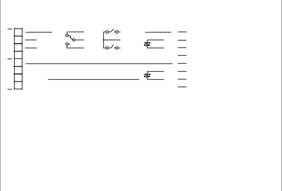
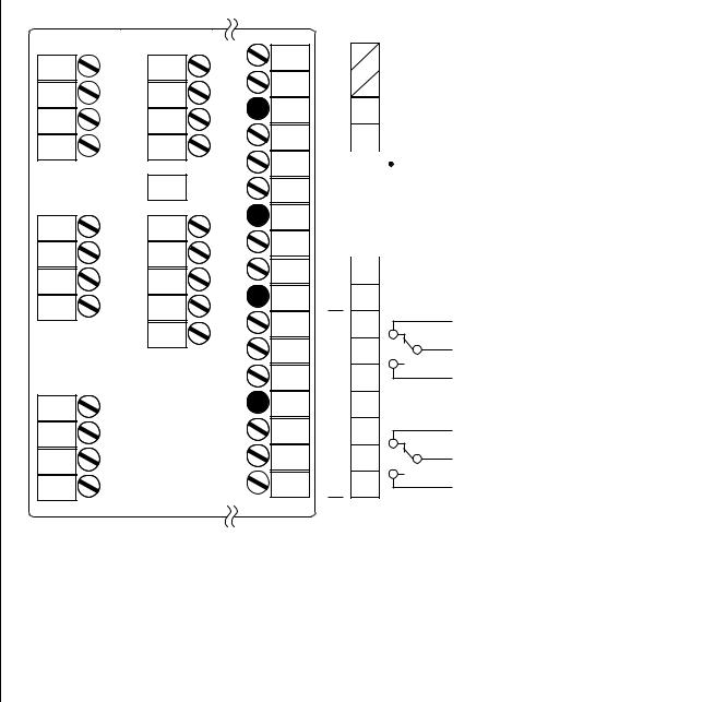
Type 703041 continued |
|
|
|
|
|
|
Outputs and interfaces - terminal strip 1 (option board) |
|
|
|
|
||
Analog |
Relay |
2 relays |
Solid-state |
PROFIBUS |
RS422 |
RS485 |
output |
(changeover) |
(n.o. make) |
relay |
|
|
|
<![endif]>Option 2 Option 1
1
2
3
4
5
6
7
8
+
Ux / Ix
-
Analog output 5 (Out5)
Ö |
Out5 |
P |
S |
Binary output 5 (Out5)
Out8 |
|
Binary output 5+8 |
Binary output 5 |
(Out5+Out8) |
(Out5) |
|
|
+ |
(not possible!) |
(not possible!) |
|
||||
|
Ux / Ix |
|
|
|
|
|
- |
|
|
|
|
|
||
Analog output 6 |
|
Binary output 6 |
||
(Out6) |
|
(Out6) |
||
VP (+5 V) |
|
RxD + |
|
|
|
|
|
||
RxD/TxD-P (B) |
|
RxD - |
|
|
|
|
|
||
RxD/TxD-N (A) |
|
TxD + |
|
RxD/TxD + |
|
|
|||
DGND |
|
TxD - |
|
RxD/TxD - |
|
|
|||
VP (+5 V) |
|
RxD + |
|
|
|
|
|
||
RxD/TxD-P (B) |
|
RxD - |
|
|
|
|
|
||
RxD/TxD-N (A) |
|
TxD + |
|
RxD/TxD + |
|
|
|||
DGND |
|
TxD - |
|
RxD/TxD - |
|
|
H Note numbering of outputs.
v Chapter 8.5 “Outputs “OutP””
<![endif]>connection Electrical 4
Type 703041 continued
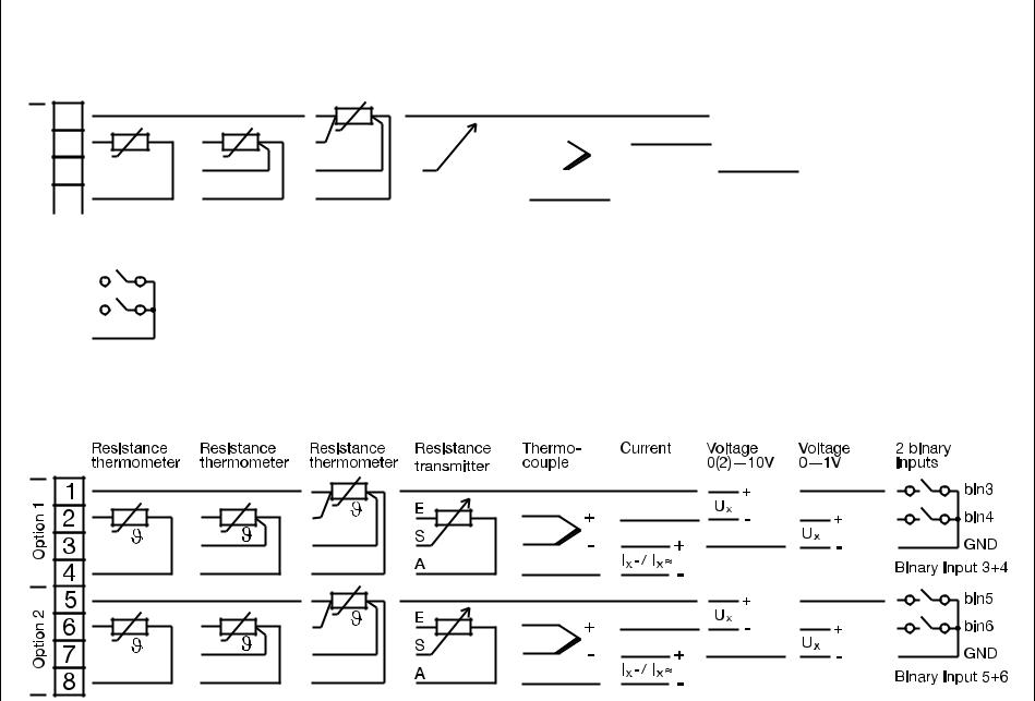
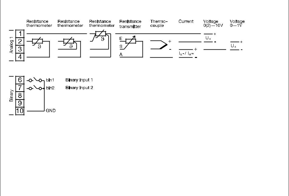
Analog input 1 and binary inputs 1+2 - terminal strip 2
<![endif]>Analog 1
Resistance thermometer
1 |
|
|
2 |
|
|
3 |
||
|
||
4 |
|
Resistance |
Resistance |
Resistance |
Thermo- |
Current |
Voltage |
Voltage |
thermometer |
thermometer |
transmitter |
couple |
|
0(2)—10V |
0—1V |
|
|
|
|
|
|
|
|
|
|
|
|
+ |
|
|
|
|
||||
|
|
|
|
|
|
|
|
|
|
|
||||||||
E |
|
|
|
|
|
+ |
|
|
|
|
|
Ux |
|
+ |
||||
|
|
|
|
|
|
|
|
- |
|
|
||||||||
S |
|
|
|
- |
|
|
|
+ |
|
|
|
|
|
Ux |
||||
|
|
|
|
|
|
|
|
|
|
|
|
|
- |
|||||
|
|
|
|
|||||||||||||||
|
|
|
|
|
|
|
|
|
|
|
|
|
|
|
||||
A |
|
|
|
|
Ix- / Ix~ |
|
|
|
||||||||||
|
|
|
|
|
|
|
|
|
- |
|
|
|
|
|
|
|
|
|
|
|
|
|
|
|
|
|
|
|
|
||||||||
| <![if ! IE]> <![endif]>Logic |
|
|
|
|
|
|
|
6 |
|
|
bin1 |
Binary input 1 |
As an alternative to binary outputs 3 and 4 |
||
|
|
||||||
|
|
|
|
|
|
|
(configurable)! |
|
|
7 |
|
|
bin2 |
Binary input 2 |
|
|
|
|
|
|
|||
|
|
8 |
|
|
GND |
|
|
Analog input 2 and binary inputs 3...6 - terminal strip 1 (option boards)
<![if ! IE]><![endif]>19
<![endif]>connection Electrical 4
<![endif]>20
1 |
2 |
1 |
1 |
2 |
2 |
3 |
3 |
4 |
4 |
5 |
6 |
6 |
7 |
7 |
8 |
8 |
9 |
|
10 |
9
10
11
12
3
L1(L+)
N(L+)
4
5
6
8
9
11
12
13
15
16
17
Supply and outputs - terminal strip 3
| <![if ! IE]> <![endif]>Supply |
|
L1 |
|
N |
|
L- |
|
|
|
|
L1 |
|
L+ |
||
|
|
L+ |
|
|
|
||
|
|
|
110—240V AC |
|
20—30V AC/DC |
||
|
|
N |
|
|
|||
|
|
L- |
|
|
|
|
|
|
|
4 |
|
|
|
|
|
|
|
|
|
|
|
|
|
|
|
5 |
|
|
|
|
|
|
|
|
|
|
|
|
|
|
|
6 |
|
|
|
|
|
|
|
|
|
|
|
|
|
|
|
|
|
|
|
|
|
| <![if ! IE]> <![endif]>= |
|
8 |
|
|
+ |
17V/20mA |
Supply for 2-wire transmitter |
|
|
||||||
| <![if ! IE]> <![endif]>U |
|
|
U= |
(off-load voltage approx. 25V) |
|||
|
|
9 |
|
|
- |
|
|
|
|
|
|
|
|
||
|
11 |
Ö |
|
|
|
12 |
P |
230V/3A |
Binary output 1 (Out1) |
| <![if ! IE]> <![endif]>Relays |
13 |
S |
|
|
15 |
Ö |
|
|
|
|
|
|
||
|
16 |
P |
230V/3A |
Binary output 2 (Out2) |
|
17 |
S |
|
|
Outputs - terminal strip 2
|
|
6 |
|
|
|
|
|
| <![if ! IE]> <![endif]>Logic |
7 |
|
|
|
|
|
|
8 |
|
|
Out3 (+) |
Binary output 3 |
Logic output level 12V or 18V |
||
|
|
|
|
||||
|
|
9 |
|
|
Out4 (+) |
Binary output 4 |
(see type code) |
|
|
|
|
|
|||
|
|
10 |
|
|
GND (-) |
|
|
|
|
|
|
|
|
||
| <![if ! IE]> <![endif]>703042/43/44 Type 2.3.4 |
<![if ! IE]> <![endif]>connection Electrical 4 |
|
|
Type 703042/43/44 continued |
|
|
|
Outputs and interfaces - terminal strip 1 (option boards) |
|
||
Analog |
Relay |
2 relays |
Solid-state |
output |
(changeover) |
(n.o. make) |
relay |
| <![if ! IE]> <![endif]>1 |
1 |
|
|
Ö |
Out5 |
2 |
|
+ |
P |
|
|
| <![if ! IE]> <![endif]>Option |
Ux / Ix |
|
|||
3 |
- |
S |
Out8 |
4 |
Analog output 5 |
Binary output 5 |
Binary output 5+8 |
Binary output 5 |
|
(Out5) |
(Out5) |
(Out5+Out8) |
(Out5) |
||
|
| <![if ! IE]> <![endif]>2 |
5 |
|
|
Ö |
Out6 |
6 |
|
+ |
P |
|
|
| <![if ! IE]> <![endif]>Option |
Ux / Ix |
|
|||
7 |
- |
S |
Out9 |
8 |
Analog output 6 |
Binary output 6 |
Binary output 6+9 |
Binary output 6 |
|
(Out6) |
(Out6) |
(Out6+Out9) |
(Out6) |
||
|
| <![if ! IE]> <![endif]>3 |
9 |
|
|
Ö |
Out7 |
10 |
|
+ |
P |
|
|
| <![if ! IE]> <![endif]>Option |
Ux / Ix |
|
|||
11 |
- |
S |
Out0 |
12 |
Analog output 7 |
Binary output 7 |
Binary output 7+10 |
Binary output 7 |
|
(Out7) |
(Out7) |
(Out7+Out0) |
(Out7) |
||
|
H Note numbering of outputs.
v Chapter 8.5 “Outputs “OutP””
<![if ! IE]><![endif]>21
PROFIBUS |
RS422 |
RS485 |
||||||
|
|
VP (+5 V) |
|
|
RxD + |
|
|
|
|
|
|
|
|
|
|
||
|
|
RxD/TxD-P (B) |
|
|
RxD - |
|
|
|
|
|
|
|
|
|
|
||
|
|
RxD/TxD-N (A) |
|
|
TxD + |
|
|
RxD/TxD + |
|
|
|
|
|
|
|||
|
|
DGND |
|
|
TxD - |
|
|
RxD/TxD - |
|
|
|
|
|
|
|||
|
|
VP (+5 V) |
|
|
RxD + |
|
|
|
|
|
|
|
|
|
|
||
|
|
RxD/TxD-P (B) |
|
|
RxD - |
|
|
|
|
|
|
|
|
|
|
||
|
|
RxD/TxD-N (A) |
|
|
TxD + |
|
|
RxD/TxD + |
|
|
|
|
|
|
|||
|
|
DGND |
|
|
TxD - |
|
|
RxD/TxD - |
|
|
|
|
|
|
|||
|
|
VP (+5 V) |
|
|
RxD + |
|
|
|
|
|
|
|
|
|
|
||
|
|
RxD/TxD-P (B) |
|
|
RxD - |
|
|
|
|
|
|
|
|
|
|
||
|
|
RxD/TxD-N (A) |
|
|
TxD + |
|
|
RxD/TxD + |
|
|
|
|
|
|
|||
|
|
DGND |
|
|
TxD - |
|
|
RxD/TxD - |
|
|
|
|
|
|
|||
<![endif]>connection Electrical 4
<![endif]>22
Type 703042/43/44 continued
Analog input 1 and binary inputs 1+2 - terminal strip 2
<![endif]>connection Electrical 4
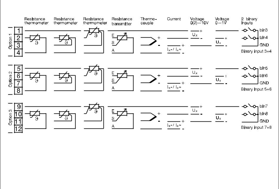
Type 703042/43/44 continued
Analog input 2 and binary inputs 3...8 - terminal strip 1 (option boards)
<![if ! IE]><![endif]>23
<![endif]>connection Electrical 4
4 Electrical connection
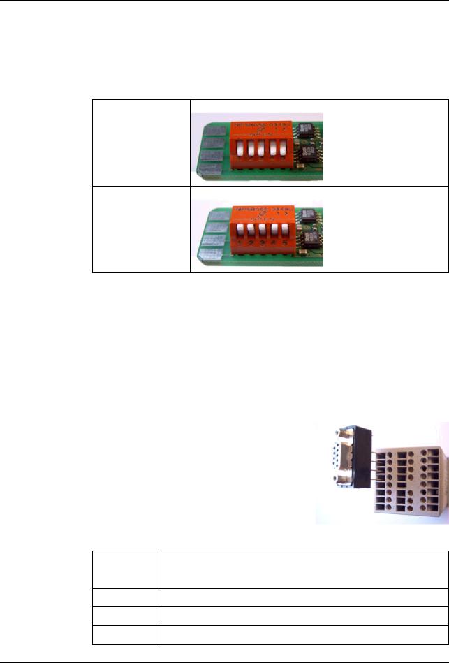
4.3.3 Termination resistor for the RS422/485 serial interface
For fault-free operation of several devices in a line structure, their internal termination resistors must be activated at the start and end.
h Pull plug-in module out towards the front by pressing on the knurled areas
h Using a ballpoint pen, press all the white switches into the same direction
Bus termination |
h Push all 5 switches down |
resistor active: |
|
No bus termination |
h Push all 5 switches up |
(ex-factory) |
|
|
h Re-insert the module back into the housing |
|
|
Check |
h Press the P+ Ikeys |
|
To the right of the green “VErS” display, “ON” is shown for active and “OFF“ for inac- |
|
tive termination resistors. |
4.3.4 Connection of the PROFIBUS-DP connector
Mounting the |
h Identify option slot with the PROFIBUS-DP interface by means of the |
adapter |
type code (in the case of pre-configured devices) |
|
In this example, the PROFIBUS-DP |
|
interface is in option slot 1 |
|
HTo fit the D-SUB adapter, open the housing |
|
of the adapter; otherwise the terminal |
|
screws are hided by the adapter. |
Assignment of the 9-pole D-SUB socket
Pin: Signal |
Designation |
|
|
1: VP |
Supply voltage positive |
2:RxD/TxD-P Receive/Transmit data positive
3:RxD/TxD-N Receive/Transmit data negative
4:DGND Ground
24
Loading...