


 Loading...
JUMO safetyM STB/STW
Safety temperature limiter, safety temperature monitor according to DIN EN 14597
B 701150.0
Operating Manual
(translation of the German
original manual)
2014-05-01 /00564764

Operating overview

|
Operating overview . . . . . . . . . . . . . . . . . . . . . . . . . . . . . . . . . . . . . . . . . . . . . . . . . . . . . . . . . . |
. 2 |
1 |
Brief description . . . . . . . . . . . . . . . . . . . . . . . . . . . . . . . . . . . . . . . . . . . . . . . . . . . . . . . . . . . . |
10 |
1.1 |
Safety temperature monitor (STW) . . . . . . . . . . . . . . . . . . . . . . . . . . . . . . . . . . . . . . . . . . . . . . . . . . . . . |
10 |
1.2 |
Safety temperature limiter (STB). . . . . . . . . . . . . . . . . . . . . . . . . . . . . . . . . . . . . . . . . . . . . . . . . . . . . . . |
10 |
1.3 |
Safety information. . . . . . . . . . . . . . . . . . . . . . . . . . . . . . . . . . . . . . . . . . . . . . . . . . . . . . . . . . . . . . . . . . |
11 |
2 |
Identifying the device version . . . . . . . . . . . . . . . . . . . . . . . . . . . . . . . . . . . . . . . . . . . . . . . . . |
12 |
2.1 |
Scope of delivery . . . . . . . . . . . . . . . . . . . . . . . . . . . . . . . . . . . . . . . . . . . . . . . . . . . . . . . . . . . . . . . . . . |
14 |
2.2 |
Device software versions . . . . . . . . . . . . . . . . . . . . . . . . . . . . . . . . . . . . . . . . . . . . . . . . . . . . . . . . . . . . |
15 |
2.3 |
Serial number . . . . . . . . . . . . . . . . . . . . . . . . . . . . . . . . . . . . . . . . . . . . . . . . . . . . . . . . . . . . . . . . . . . . . |
15 |
2.4 |
Service addresses . . . . . . . . . . . . . . . . . . . . . . . . . . . . . . . . . . . . . . . . . . . . . . . . . . . . . . . . . . . . . . . . . |
15 |
3 |
Installation . . . . . . . . . . . . . . . . . . . . . . . . . . . . . . . . . . . . . . . . . . . . . . . . . . . . . . . . . . . . . . . . . |
17 |
3.1 |
Dimensions . . . . . . . . . . . . . . . . . . . . . . . . . . . . . . . . . . . . . . . . . . . . . . . . . . . . . . . . . . . . . . . . . . . . . . . |
17 |
3.2 |
Installation location, DIN rail installation. . . . . . . . . . . . . . . . . . . . . . . . . . . . . . . . . . . . . . . . . . . . . . . . . |
18 |
3.3 |
Close mounting. . . . . . . . . . . . . . . . . . . . . . . . . . . . . . . . . . . . . . . . . . . . . . . . . . . . . . . . . . . . . . . . . . . . |
18 |
3.4 |
Dismantling . . . . . . . . . . . . . . . . . . . . . . . . . . . . . . . . . . . . . . . . . . . . . . . . . . . . . . . . . . . . . . . . . . . . . . . |
19 |
3.5 |
Electrical isolation. . . . . . . . . . . . . . . . . . . . . . . . . . . . . . . . . . . . . . . . . . . . . . . . . . . . . . . . . . . . . . . . . . |
20 |
3.6 |
Use of the setup interface . . . . . . . . . . . . . . . . . . . . . . . . . . . . . . . . . . . . . . . . . . . . . . . . . . . . . . . . . . . |
20 |
4 |
Electrical connection . . . . . . . . . . . . . . . . . . . . . . . . . . . . . . . . . . . . . . . . . . . . . . . . . . . . . . . . |
21 |
4.1 |
Installation notes. . . . . . . . . . . . . . . . . . . . . . . . . . . . . . . . . . . . . . . . . . . . . . . . . . . . . . . . . . . . . . . . . . . |
21 |
4.2 |
Connection diagram . . . . . . . . . . . . . . . . . . . . . . . . . . . . . . . . . . . . . . . . . . . . . . . . . . . . . . . . . . . . . . . . |
23 |
5 |
Commissioning the device . . . . . . . . . . . . . . . . . . . . . . . . . . . . . . . . . . . . . . . . . . . . . . . . . . . . |
27 |
5.1 |
Display and operating elements . . . . . . . . . . . . . . . . . . . . . . . . . . . . . . . . . . . . . . . . . . . . . . . . . . . . . . . |
27 |
5.2 |
Setting the display after switch-on . . . . . . . . . . . . . . . . . . . . . . . . . . . . . . . . . . . . . . . . . . . . . . . . . . . . . |
27 |
Inhalt

Inhalt
5.3 Selecting and editing parameters (plausibility inquiry for input values) . . . . . . . . . . . . . . . . . . . . . . . . .29 5.4 Aborting edit . . . . . . . . . . . . . . . . . . . . . . . . . . . . . . . . . . . . . . . . . . . . . . . . . . . . . . . . . . . . . . . . . . . . . .30 5.5 Alarm acknowledgement using the Reset key (only for temperature limiters STB) . . . . . . . . . . . . . . . .30 5.6 Alarm acknowledgement via binary input (only for temperature limiters STB). . . . . . . . . . . . . . . . . . . .30 5.7 Lead sealing the device . . . . . . . . . . . . . . . . . . . . . . . . . . . . . . . . . . . . . . . . . . . . . . . . . . . . . . . . . . . . .31
6 |
Safety Manual . . . . . . . . . . |
. . . . . . . . . . . . . . . . . . . . . . . . . . . . . . . . . . . . . . . . . . . . . . . . . . . . |
32 |
6.1 |
Brief description . . . . . . . . . . . |
. . . . . . . . . . . . . . . . . . . . . . . . . . . . . . . . . . . . . . . . . . . . . . . . . . . . . . . |
. 32 |
6.2 |
Safety temperature monitor (STW) . . . . . . . . . . . . . . . . . . . . . . . . . . . . . . . . . . . . . . . . . . . . . . . . . . . . |
. 32 |
|
6.2.1 |
Safe operating status STW . . . . . . |
. . . . . . . . . . . . . . . . . . . . . . . . . . . . . . . . . . . . . . . . . . . . . . . . . . . . . . . . . . . . . . . |
.32 |
6.3 |
Safety temperature limiter (STB). . . . . . . . . . . . . . . . . . . . . . . . . . . . . . . . . . . . . . . . . . . . . . . . . . . . . . . |
33 |
|
6.3.1 |
Safe operating status STB . . . . . . |
. . . . . . . . . . . . . . . . . . . . . . . . . . . . . . . . . . . . . . . . . . . . . . . . . . . . . . . . . . . . . . . . |
33 |
6.4 |
Relevant standards. . . . . . . . . |
. . . . . . . . . . . . . . . . . . . . . . . . . . . . . . . . . . . . . . . . . . . . . . . . . . . . . . . . |
33 |
6.5 |
Validity of the Safety Manual . |
. . . . . . . . . . . . . . . . . . . . . . . . . . . . . . . . . . . . . . . . . . . . . . . . . . . . . . . . |
34 |
6.6 |
Connection possibilities of the sensors (SIL) . . . . . . . . . . . . . . . . . . . . . . . . . . . . . . . . . . . . . . . . . . . . . |
34 |
|
6.7 |
Standards and definitions. . . . |
. . . . . . . . . . . . . . . . . . . . . . . . . . . . . . . . . . . . . . . . . . . . . . . . . . . . . . . . |
37 |
6.7.1 |
Terms and abbreviations acc. to DIN EN 14597 . . . . . . . . . . . . . . . . . . . . . . . . . . . . . . . . . . . . . . . . . . . . . . . . . . . . . . |
37 |
|
6.7.2 |
Terms and abbreviations acc. to DIN EN 61 508 and DIN EN 61 511. . . . . . . . . . . . . . . . . . . . . . . . . . . . . . . . . . . . . . |
38 |
|
6.8 |
Safety instrumented parameters related to the temperature monitoring unit . . . . . . . . . . . . . . . . . . . . |
41 |
|
6.8.1 |
Failure rates and SFF for 701150... |
23 (AC 230 V) . . . . . . . . . . . . . . . . . . . . . . . . . . . . . . . . . . . . . . . . . . . . . . . . . . . . . |
41 |
6.8.2 |
Failure rates and SFF for 701150... |
25 (AC/DC 24 V) . . . . . . . . . . . . . . . . . . . . . . . . . . . . . . . . . . . . . . . . . . . . . . . . . . . |
42 |
6.9 |
Determining the Safety Integrity Level (SIL) . . . . . . . . . . . . . . . . . . . . . . . . . . . . . . . . . . . . . . . . . . . . . . |
43 |
|
6.9.1 |
Safety integrity of the hardware . . |
. . . . . . . . . . . . . . . . . . . . . . . . . . . . . . . . . . . . . . . . . . . . . . . . . . . . . . . . . . . . . . . . |
45 |
6.9.2 |
Safety-relevant system properties |
. . . . . . . . . . . . . . . . . . . . . . . . . . . . . . . . . . . . . . . . . . . . . . . . . . . . . . . . . . . . . . . . |
46 |
6.10 Determining the achieved Performance Level PL. . . . . . . . . . . . . . . . . . . . . . . . . . . . . . . . . . . . . . . . . .48

6.10.1 |
Terms and abbreviations acc. to DIN EN ISO 13849 . . . . . . . . . . . . . . . . . . . . . . . . . . . . . . . . . . . . . . . . . . . . . . . . . |
.48 |
6.11 Connection possibilities of the sensors (PL). . . . . . . . . . . . . . . . . . . . . . . . . . . . . . . . . . . . . . . . . . . . . . |
51 |
|
6.11.1 Calculations DIN EN ISO 13849-1 Performance Level - low voltage 230 V . . . . . . . . . . . . . . . . . . . . . . . . . . . . . . . . . |
53 |
|
6.11.2 Calculations DIN EN ISO 13849-1 Performance Level - extra low voltage (ELV) 24 V . . . . . . . . . . . . . . . . . . . . . . . . . |
53 |
|
6.11.3 Contribution to risk minimization through the control system . . . . . . . . . . . . . . . . . . . . . . . . . . . . . . . . . . . . . . . . . . . |
54 |
|
6.12 Evaluating the achieved Performance Level PL and the relationship to the SIL . . . . . . . . . . . . . . . . . . |
56 |
|
6.13 Other applicable device documentation. . . . . . . . . . . . . . . . . . . . . . . . . . . . . . . . . . . . . . . . . . . . . . . . . |
59 |
|
6.14 Behavior during operation and in case of malfunction . . . . . . . . . . . . . . . . . . . . . . . . . . . . . . . . . . . . . . |
59 |
|
6.15 |
Regular tests. . . . . . . . . . . . . . . . . . . . . . . . . . . . . . . . . . . . . . . . . . . . . . . . . . . . . . . . . . . . . . . . . . . . . . |
59 |
6.15.1 |
Recommended tests for temperature probes . . . . . . . . . . . . . . . . . . . . . . . . . . . . . . . . . . . . . . . . . . . . . . . . . . . . . . . . |
59 |
6.16 |
Certificates . . . . . . . . . . . . . . . . . . . . . . . . . . . . . . . . . . . . . . . . . . . . . . . . . . . . . . . . . . . . . . . . . . . . . . . |
61 |
7 |
Configuration level . . . . . . . . . . . . . . . . . . . . . . . . . . . . . . . . . . . . . . . . . . . . . . . . . . . . . . . . . . |
70 |
7.1 |
Navigation principle . . . . . . . . . . . . . . . . . . . . . . . . . . . . . . . . . . . . . . . . . . . . . . . . . . . . . . . . . . . . . . . . |
70 |
7.2 |
Analog inputs . . . . . . . . . . . . . . . . . . . . . . . . . . . . . . . . . . . . . . . . . . . . . . . . . . . . . . . . . . . . . . . . . . . . . |
71 |
7.2.1 |
Connection . . . . . . . . . . . . . . . . . . . . . . . . . . . . . . . . . . . . . . . . . . . . . . . . . . . . . . . . . . . . . . . . . . . . . . . . . . . . . . . . . . |
71 |
7.2.2 |
Sensor type 1 . . . . . . . . . . . . . . . . . . . . . . . . . . . . . . . . . . . . . . . . . . . . . . . . . . . . . . . . . . . . . . . . . . . . . . . . . . . . . . . . |
72 |
7.2.3 |
Offset 1 . . . . . . . . . . . . . . . . . . . . . . . . . . . . . . . . . . . . . . . . . . . . . . . . . . . . . . . . . . . . . . . . . . . . . . . . . . . . . . . . . . . . . |
73 |
7.2.4 |
Lead wire resistance 1 . . . . . . . . . . . . . . . . . . . . . . . . . . . . . . . . . . . . . . . . . . . . . . . . . . . . . . . . . . . . . . . . . . . . . . . . . |
73 |
7.2.5 |
Filter time 1 . . . . . . . . . . . . . . . . . . . . . . . . . . . . . . . . . . . . . . . . . . . . . . . . . . . . . . . . . . . . . . . . . . . . . . . . . . . . . . . . . . |
73 |
7.2.6 |
Scaling start 1 . . . . . . . . . . . . . . . . . . . . . . . . . . . . . . . . . . . . . . . . . . . . . . . . . . . . . . . . . . . . . . . . . . . . . . . . . . . . . . . . |
73 |
7.2.7 |
Scaling end 1 . . . . . . . . . . . . . . . . . . . . . . . . . . . . . . . . . . . . . . . . . . . . . . . . . . . . . . . . . . . . . . . . . . . . . . . . . . . . . . . . . |
73 |
7.2.8 |
Sensor type 2 . . . . . . . . . . . . . . . . . . . . . . . . . . . . . . . . . . . . . . . . . . . . . . . . . . . . . . . . . . . . . . . . . . . . . . . . . . . . . . . . |
74 |
7.2.9 |
Offset 2 . . . . . . . . . . . . . . . . . . . . . . . . . . . . . . . . . . . . . . . . . . . . . . . . . . . . . . . . . . . . . . . . . . . . . . . . . . . . . . . . . . . . . |
75 |
7.2.10 |
Lead wire resistance 2 . . . . . . . . . . . . . . . . . . . . . . . . . . . . . . . . . . . . . . . . . . . . . . . . . . . . . . . . . . . . . . . . . . . . . . . . . |
75 |
Inhalt

Inhalt
7.2.11 Filter time 2 . . . . . . . . . . . . . . . . . . . . . . . . . . . . . . . . . . . . . . . . . . . . . . . . . . . . . . . . . . . . . . . . . . . . . . . . . . . . . . . . . .75 7.2.12 Scaling start 2 . . . . . . . . . . . . . . . . . . . . . . . . . . . . . . . . . . . . . . . . . . . . . . . . . . . . . . . . . . . . . . . . . . . . . . . . . . . . . . . .75 7.2.13 Scaling end 2 . . . . . . . . . . . . . . . . . . . . . . . . . . . . . . . . . . . . . . . . . . . . . . . . . . . . . . . . . . . . . . . . . . . . . . . . . . . . . . . . .75
7.3 Limiter/monitor . . . . . . . . . . . . . . . . . . . . . . . . . . . . . . . . . . . . . . . . . . . . . . . . . . . . . . . . . . . . . . . . . . . .76
7.3.1 Device function . . . . . . . . . . . . . . . . . . . . . . . . . . . . . . . . . . . . . . . . . . . . . . . . . . . . . . . . . . . . . . . . . . . . . . . . . . . . . . .76 7.3.2 Switching behavior . . . . . . . . . . . . . . . . . . . . . . . . . . . . . . . . . . . . . . . . . . . . . . . . . . . . . . . . . . . . . . . . . . . . . . . . . . . .77 7.3.3 Limit value, hysteresis . . . . . . . . . . . . . . . . . . . . . . . . . . . . . . . . . . . . . . . . . . . . . . . . . . . . . . . . . . . . . . . . . . . . . . . . . .79 7.3.4 Pre-alarm function . . . . . . . . . . . . . . . . . . . . . . . . . . . . . . . . . . . . . . . . . . . . . . . . . . . . . . . . . . . . . . . . . . . . . . . . . . . . .79 7.3.5 Pre-alarm, hysteresis . . . . . . . . . . . . . . . . . . . . . . . . . . . . . . . . . . . . . . . . . . . . . . . . . . . . . . . . . . . . . . . . . . . . . . . . . . .79 7.3.6 Limit value difference, hysteresis . . . . . . . . . . . . . . . . . . . . . . . . . . . . . . . . . . . . . . . . . . . . . . . . . . . . . . . . . . . . . . . . .80 7.3.7 Setting range min. (formerly ALHI) . . . . . . . . . . . . . . . . . . . . . . . . . . . . . . . . . . . . . . . . . . . . . . . . . . . . . . . . . . . . . . .80 7.3.8 Setting range max. (formerly ALLO) . . . . . . . . . . . . . . . . . . . . . . . . . . . . . . . . . . . . . . . . . . . . . . . . . . . . . . . . . . . . . .80
7.4 Binary input. . . . . . . . . . . . . . . . . . . . . . . . . . . . . . . . . . . . . . . . . . . . . . . . . . . . . . . . . . . . . . . . . . . . . . .81
7.4.1 Function . . . . . . . . . . . . . . . . . . . . . . . . . . . . . . . . . . . . . . . . . . . . . . . . . . . . . . . . . . . . . . . . . . . . . . . . . . . . . . . . . . . . .81
7.5 Analog output . . . . . . . . . . . . . . . . . . . . . . . . . . . . . . . . . . . . . . . . . . . . . . . . . . . . . . . . . . . . . . . . . . . . .82
7.5.1 Function . . . . . . . . . . . . . . . . . . . . . . . . . . . . . . . . . . . . . . . . . . . . . . . . . . . . . . . . . . . . . . . . . . . . . . . . . . . . . . . . . . . . .82 7.5.2 Signal type . . . . . . . . . . . . . . . . . . . . . . . . . . . . . . . . . . . . . . . . . . . . . . . . . . . . . . . . . . . . . . . . . . . . . . . . . . . . . . . . . . .82 7.5.3 Scaling start . . . . . . . . . . . . . . . . . . . . . . . . . . . . . . . . . . . . . . . . . . . . . . . . . . . . . . . . . . . . . . . . . . . . . . . . . . . . . . . . .82 7.5.4 Scaling end . . . . . . . . . . . . . . . . . . . . . . . . . . . . . . . . . . . . . . . . . . . . . . . . . . . . . . . . . . . . . . . . . . . . . . . . . . . . . . . . . .82 7.5.5 Error signal . . . . . . . . . . . . . . . . . . . . . . . . . . . . . . . . . . . . . . . . . . . . . . . . . . . . . . . . . . . . . . . . . . . . . . . . . . . . . . . . . .83 7.5.6 Behavior when leaving the scaling range . . . . . . . . . . . . . . . . . . . . . . . . . . . . . . . . . . . . . . . . . . . . . . . . . . . . . . . . . . .84
7.6 Display/operation . . . . . . . . . . . . . . . . . . . . . . . . . . . . . . . . . . . . . . . . . . . . . . . . . . . . . . . . . . . . . . . . . .85
7.6.1 Language . . . . . . . . . . . . . . . . . . . . . . . . . . . . . . . . . . . . . . . . . . . . . . . . . . . . . . . . . . . . . . . . . . . . . . . . . . . . . . . . . . . .85 7.6.2 Unit . . . . . . . . . . . . . . . . . . . . . . . . . . . . . . . . . . . . . . . . . . . . . . . . . . . . . . . . . . . . . . . . . . . . . . . . . . . . . . . . . . . . . . . .85 7.6.3 Decimal place . . . . . . . . . . . . . . . . . . . . . . . . . . . . . . . . . . . . . . . . . . . . . . . . . . . . . . . . . . . . . . . . . . . . . . . . . . . . . . . .85

7.6.4 Normal display . . . . . . . . . . . . . . . . . . . . . . . . . . . . . . . . . . . . . . . . . . . . . . . . . . . . . . . . . . . . . . . . . . . . . . . . . . . . . . .85 7.6.5 Contrast . . . . . . . . . . . . . . . . . . . . . . . . . . . . . . . . . . . . . . . . . . . . . . . . . . . . . . . . . . . . . . . . . . . . . . . . . . . . . . . . . . . . .86 7.6.6 Lighting . . . . . . . . . . . . . . . . . . . . . . . . . . . . . . . . . . . . . . . . . . . . . . . . . . . . . . . . . . . . . . . . . . . . . . . . . . . . . . . . . . . . .86 7.6.7 Time-out light . . . . . . . . . . . . . . . . . . . . . . . . . . . . . . . . . . . . . . . . . . . . . . . . . . . . . . . . . . . . . . . . . . . . . . . . . . . . . . . .86 7.6.8 Time-out operation . . . . . . . . . . . . . . . . . . . . . . . . . . . . . . . . . . . . . . . . . . . . . . . . . . . . . . . . . . . . . . . . . . . . . . . . . . . .86 7.6.9 Code . . . . . . . . . . . . . . . . . . . . . . . . . . . . . . . . . . . . . . . . . . . . . . . . . . . . . . . . . . . . . . . . . . . . . . . . . . . . . . . . . . . . . . .86
7.7 Service . . . . . . . . . . . . . . . . . . . . . . . . . . . . . . . . . . . . . . . . . . . . . . . . . . . . . . . . . . . . . . . . . . . . . . . . . .87
7.7.1 Limit switching cycle . . . . . . . . . . . . . . . . . . . . . . . . . . . . . . . . . . . . . . . . . . . . . . . . . . . . . . . . . . . . . . . . . . . . . . . . . . .87 7.7.2 Current switching cycles . . . . . . . . . . . . . . . . . . . . . . . . . . . . . . . . . . . . . . . . . . . . . . . . . . . . . . . . . . . . . . . . . . . . . . . .87 7.7.3 Operating hours . . . . . . . . . . . . . . . . . . . . . . . . . . . . . . . . . . . . . . . . . . . . . . . . . . . . . . . . . . . . . . . . . . . . . . . . . . . . . . .87
8 Technical data . . . . . . . . . . . . . . . . . . . . . . . . . . . . . . . . . . . . . . . . . . . . . . . . . . . . . . . . . . . . . . 88
8.1 Analog inputs . . . . . . . . . . . . . . . . . . . . . . . . . . . . . . . . . . . . . . . . . . . . . . . . . . . . . . . . . . . . . . . . . . . . .88 8.2 Analog output . . . . . . . . . . . . . . . . . . . . . . . . . . . . . . . . . . . . . . . . . . . . . . . . . . . . . . . . . . . . . . . . . . . . .90 8.3 Binary input. . . . . . . . . . . . . . . . . . . . . . . . . . . . . . . . . . . . . . . . . . . . . . . . . . . . . . . . . . . . . . . . . . . . . . .90 8.4 Relay outputs . . . . . . . . . . . . . . . . . . . . . . . . . . . . . . . . . . . . . . . . . . . . . . . . . . . . . . . . . . . . . . . . . . . . .90 8.5 Measuring circuit monitoring . . . . . . . . . . . . . . . . . . . . . . . . . . . . . . . . . . . . . . . . . . . . . . . . . . . . . . . . .91 8.6 Voltage supply . . . . . . . . . . . . . . . . . . . . . . . . . . . . . . . . . . . . . . . . . . . . . . . . . . . . . . . . . . . . . . . . . . . .91 8.7 Test voltages according to EN 60730, part 1 . . . . . . . . . . . . . . . . . . . . . . . . . . . . . . . . . . . . . . . . . . . . .92 8.8 Electrical safety. . . . . . . . . . . . . . . . . . . . . . . . . . . . . . . . . . . . . . . . . . . . . . . . . . . . . . . . . . . . . . . . . . . .92 8.9 Environmental influences . . . . . . . . . . . . . . . . . . . . . . . . . . . . . . . . . . . . . . . . . . . . . . . . . . . . . . . . . . . .92 8.10 Case . . . . . . . . . . . . . . . . . . . . . . . . . . . . . . . . . . . . . . . . . . . . . . . . . . . . . . . . . . . . . . . . . . . . . . . . . . . .93 8.11 Approvals/approval marks . . . . . . . . . . . . . . . . . . . . . . . . . . . . . . . . . . . . . . . . . . . . . . . . . . . . . . . . . . .94 8.12 Probes for the operating medium air . . . . . . . . . . . . . . . . . . . . . . . . . . . . . . . . . . . . . . . . . . . . . . . . . . .95 8.13 Probes for the operating medium water and oil . . . . . . . . . . . . . . . . . . . . . . . . . . . . . . . . . . . . . . . . . . .96
Inhalt

Inhalt
8.14 Probes for the operating medium water, oil and air . . . . . . . . . . . . . . . . . . . . . . . . . . . . . . . . . . . . . . . .98
9 |
Setup program . . . . . . . . . . . . . . . . . . . . . . . . . . . . . . . . . . . . . . . . . . . . . . . . . . . . . . . . . . . . |
. 99 |
9.1 |
Minimum hardware and software prerequisites: . . . . . . . . . . . . . . . . . . . . . . . . . . . . . . . . . . . . . . . . . |
.99 |
9.2 |
Displaying the device software version . . . . . . . . . . . . . . . . . . . . . . . . . . . . . . . . . . . . . . . . . . . . . . . . |
.99 |
9.3 |
Forgotten the code? . . . . . . . . . . . . . . . . . . . . . . . . . . . . . . . . . . . . . . . . . . . . . . . . . . . . . . . . . . . . . . . |
100 |
9.4 |
Special function: thermocouple reverse polarity protection. . . . . . . . . . . . . . . . . . . . . . . . . . . . . . . . . |
100 |
10 Alarm messages . . . . . . . . . . . . . . . . . . . . . . . . . . . . . . . . . . . . . . . . . . . . . . . . . . . . . . . . . . . 101 11 Error messages . . . . . . . . . . . . . . . . . . . . . . . . . . . . . . . . . . . . . . . . . . . . . . . . . . . . . . . . . . . . 102 12 What to do, if ... . . . . . . . . . . . . . . . . . . . . . . . . . . . . . . . . . . . . . . . . . . . . . . . . . . . . . . . . . . . . 107
13 Information for devices with extra code 062 GL . . . . . . . . . . . . . . . . . . . . . . . . . . . . . . . . . 109
13.1 Technical data . . . . . . . . . . . . . . . . . . . . . . . . . . . . . . . . . . . . . . . . . . . . . . . . . . . . . . . . . . . . . . . . . . .109 13.2 Alarm messages . . . . . . . . . . . . . . . . . . . . . . . . . . . . . . . . . . . . . . . . . . . . . . . . . . . . . . . . . . . . . . . . . .109 13.3 Locks . . . . . . . . . . . . . . . . . . . . . . . . . . . . . . . . . . . . . . . . . . . . . . . . . . . . . . . . . . . . . . . . . . . . . . . . . .109
14 Output behavior . . . . . . . . . . . . . . . . . . . . . . . . . . . . . . . . . . . . . . . . . . . . . . . . . . . . . . . . . . . 111

2014-05-01 |
1 Brief description 10 |
|
1 |
Brief description |
|
The safety temperature limiter (STB) and the safety temperature monitor(STW) are used to reliably detect and avert hazards that could cause injuries, are harmful to the environment or cause destruction of production plants and produced goods, at an early stage.
Its primary task is to reliably monitor thermal processes and switch the systems to an operationally safe status in the event of malfunctions.
The measured value at the analog input can be recorded by various probes or standard signals.
The limit value overrange is indicated by the installed LEDs K1and K2 (red) for each channel, and the installed relay "Alarm" switches the system to an operationally safe status (alarm range).
The high standards of DIN EN 61508 and DIN EN ISO 13849 are met by a device design, the 1oo2D structure of which ensures reliable detection of errors and, thus, can also be used for applications according to the new Machinery Directive 2006/42/EC.
1.1Safety temperature monitor (STW)
The STW is a safety component according to Machinery Directive, which, when activated, resets automatically if the probe temperature has gone below / exceeded the limit value by an amount equal to the hysteresis. Possible settings: monitoring for limit value overrange or underrange.
v Chapter 7.3.2 "Switching behavior"
1.2Safety temperature limiter (STB)
The STB is a safety component according to Machinery Directive that is permanently locked after response. Manual reset using the key is only possible once the probe temperature has gone below / exceeded the limit value by an amount equal to the hysteresis. Possible settings: monitoring for limit value overrange or underrange.
v Chapter 7.3.2 "Switching behavior"
The transparent cover can be lead sealed to prevent unauthorized operation. However, the  key remains accessible.
1.3Safety information
Symbol |
Meaning |
Explanation |
|
|
|
H |
Note |
This symbol is used to draw your attention to important information. |
|
|
|
|
|
|
|
|
|
A |
Caution |
This symbol is used when there is a risk of damage to equipment or data if the instructions are ig- |
|
|
|
|
nored or not followed correctly. |
|
|
||
|
|
|
|
|
|
|
|
Danger |
This symbol is used when there is a risk of injury to persons if the instructions are ignored or not |
|
|
V |
|
followed correctly. |
|
|
|
|
|
|
|
||
|
|
|
|
- |
|
|
|
Read |
This text contains important information and must always be read before work is continued. Han |
||
|
|
|
dling the device in any way that is not described in the Operating Manual or that is expressly forbid- |
|
|
|
|
|
den will jeopardize your warranty rights. |
|
|
|
|
|
|
|
|
v |
Reference |
This symbol refers to further information in other manuals, chapters or sections. |
|
|
|
|
|
|
|
|
|
abc1 |
Footnote |
Footnotes are remarks referring to specific points in the text marked with a superscript number. |
|
|
|
* |
|
|
|
|
|
|
|
Instructions |
This symbol indicates that an action to be performed is described. The individual steps are marked |
|
|
|
|
for action |
by an asterisk. |
|
|
|
|
|
|
|
|
2014-05-01 |
1 Brief description 11 |

2014-05-01 |
2 Identifying the device version 12 |
2 Identifying the device version
The type plate is affixed to the side of the device.
Switching behavior
Voltage supply AC 110 to 240 V:
Voltage supply AC/DC20 to 30 V:
A |
The voltage supply must correspond to the voltage given on the type plate! |

|
|
|
|
|
|
|
|
|
Basic type |
|
|
701150 |
|
|
|
|
|
|
|
Safety temperature limiters (STB) / monitors (STW) according to DIN EN 14597 |
|||
|
|
|
|
|
|
|
|
|
|
|
|
|
|
|
|
|
|
|
|
|
Version |
|
|
|
8 |
|
|
|
|
|
Factory setting |
|
|||
|
9 |
|
|
|
|
|
Configured according to customer specifications |
||||
|
|
|
|
|
|
|
|
|
|
|
|
|
|
|
|
|
|
|
|
|
Language |
|
|
|
|
|
01 |
|
|
|
German (factory setting) |
|
|||
|
|
|
02 |
|
|
|
English |
|
|||
|
|
|
03 |
|
|
|
French |
|
|||
|
|
|
|
|
|
|
|
|
|
|
|
|
|
|
|
|
|
|
|
|
Switching behavior |
|
|
|
|
|
|
|
0251 |
|
Safety temperature monitor |
max. alarm (inverse, N/C contact) |
|||
|
|
|
|
|
0252 |
|
Safety temperature monitor |
min. alarm (direct, N/O contact) |
|||
|
|
|
|
|
0253 |
|
Safety temperature limiter max. alarm (inverse, N/C contact) |
||||
|
|
|
|
|
0254 |
|
Safety temperature limiter min. alarm (direct, N/O contact) |
||||
|
|
|
|
|
|
|
|
|
|
||
|
|
|
|
|
|
|
|
|
Measuring input1 (programmable) |
||
|
|
|
|
|
|
|
|
|
|||
|
|
|
|
|
|
|
1003 |
1x |
Pt100 in 2-wire circuit |
|
|
|
|
|
|
|
|
|
2001 |
2x Pt100 in 3-wire circuit (ex-factory) |
|||
|
|
|
|
|
|
|
2003 |
2x |
Pt100 in 2-wire circuit |
|
|
|
|
|
|
|
|
|
2006 |
2x |
Pt1000 in 3-wire circuit |
|
|
|
|
|
|
|
|
|
2037 |
2x W3Re-W25Re "D" |
|
||
|
|
|
|
|
|
|
2039 |
2x |
Cu-CuNi "T" |
|
|
|
|
|
|
|
|
|
2040 |
2x |
Fe-CuNi "J" |
|
|
|
|
|
|
|
|
|
2041 |
2x |
Cu-CuNi "U" |
|
|
|
|
|
|
|
|
|
2042 |
2x |
Fe-CuNi "L" |
|
|
|
|
|
|
|
|
|
2043 |
2x |
NiCr-Ni "K" |
|
|
|
|
|
|
|
|
|
|
|
|
|
|
2014-05-01 |
2 Identifying the device version 13 |
2014-05-01 |
|
|
|
|
|
|
|
|
|
2 Identifying the device version |
14 |
|||||
|
|
|
|
|
|
|
|
|
|
|
|
|
|
|
||
|
|
|
|
|
|
|
2044 |
|
|
2x Pt10Rh-Pt "S" |
|
|||||
|
|
|
|
|
|
|
|
|
|
|||||||
|
|
|
|
|
|
|
2045 |
|
|
2x Pt13Rh-Pt "R" |
|
|||||
|
|
|
|
|
|
|
2046 |
|
|
2x Pt30Rh-Pt6Rh "B" |
|
|||||
|
|
|
|
|
|
|
2048 |
|
|
2x NiCrSi-NiSi "N" |
|
|||||
|
|
|
|
|
|
|
1053 |
|
|
1x 4 to 20 mA |
|
|
|
|||
|
|
|
|
|
|
|
2053 |
|
|
2x 4 to 20 mA |
|
|
|
|||
|
|
|
|
|
|
|
|
|
|
|
Voltage supply |
|
|
|
||
|
|
|
|
|
|
|
|
|
23 AC 110 to 240 V +10 % /-15 %, 48 to 63 Hz |
|
||||||
|
|
|
|
|
|
|
|
|
25 20 to 30 V AC/DC, 48 to 63 Hz |
|
||||||
|
|
|
|
|
|
|
|
|
|
|
|
|
|
|
||
|
|
|
|
|
|
|
|
|
|
|
Analog output (configurable) |
|
||||
|
|
|
|
|
|
|
|
|
|
|
001 |
0 to 20 mA |
|
|||
|
|
|
|
|
|
|
|
|
|
|
005 |
4 to 20 mA (ex-factory) |
|
|||
|
|
|
|
|
|
|
|
|
|
|
040 |
0 to 10 V |
|
|||
|
|
|
|
|
|
|
|
|
|
|
070 |
2 to 10 V |
|
|||
|
|
|
|
|
|
|
|
|
|
|
|
|
Extra code |
|
||
|
|
|
|
|
|
|
|
|
|
|
|
|
|
058 SIL and PL approval |
|
|
|
|
|
|
|
|
|
|
|
|
|
|
|
|
062 GL approval |
|
|
|
|
|
|
|
|
|
|
|
|
|
|
|
|
|
|
|
|
|
|
|
|
|
|
|
|
|
|
|
|
|
|
|
|
701150 / |
8 - |
01 - |
0253 - 2001 - |
23 / |
005 |
, |
062 |
|
||||||||
1. The first number on the measuring input means single probe "1“ or double probe "2“
2.1Scope of delivery
-JUMOsafety M STB/STW in the version ordered
-Operating Manual B701150.0
2.2Device software versions
Diagnosis module version: 257.01.01
Analog channel 1 version: 258.01.02
Analog channel 2 version: 258.01.02
2.3Serial number
The serial number is indicated on the device. h Press the  +
+  keys
keys
Construction:
The first 8 digits specify the serial number: 01424103 Digit 9 and 10 the production plant in Fulda: 01
Digit 11 (second line) the hardware version: 4 Digit 12 and 13 the year: 2011
Digit 14 and 15 the calendar week: 03 Digit 16 to 19 consecutive numbers: 1234
2.4 |
Service addresses |
Austria: |
|
|
Switzerland: |
||
Telephone:+43 |
1 610610 |
Telephone:+41 44 928 24 44 |
|||||
|
|
||||||
Phone support in Germany: |
Fax: |
+43 |
1 6106140 |
Fax: |
+41 44 928 24 48 |
||
Telephone:+49 661 6003-9135 |
Email: |
info@jumo.at |
Email: |
info@jumo.ch |
|||
Fax: |
+49 661 6003-881899 |
|
|
|
|
|
|
Email: |
service@jumo.net |
|
|
|
|
|
|
2014-05-01 |
2 Identifying the device version 15 |

2014-05-01 |
2 Identifying the device version 16 |
This operating manual is a translation of the German original manual. It is valid for the following hardware and software versions:
Diagnosis module from version: 257.01.01 Analog channel 1 from version: 258.01.02 Analog channel 2 from version: 258.01.02
Hardware version: 0
h Press the  +
+  keys
keys
Keep the operating manual in a place accessible to all users at all times.
All necessary settings are described in this Operating Manual.
A Handling the device in any way that is not described in the OperatingManual or that is expressly forbidden will jeopardize your warranty rights and may disable the safety function.
It is forbidden to access the inside of the device!
Repairs may only be performed by JUMO at the head office in Fulda.
Please contact the nearest subsidiary or the head office should you encounter any problems.
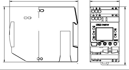
3 Installation
3.1Dimensions
104,8 |
45 |
|
85 |
|
89,4 |
2014-05-01 |
3 Installation |
17 |

2014-05-01 |
3 Installation 18 |
3.2Installation location, DIN rail installation
The device is not suitable for use in potentially explosive atmospheres.
V The device is hooked into a 35 mm DIN rail (EN 60715) from the front and pushed down to engage.
vThe ambient conditions at the installation site must meet the requirements specified in the technical data.
Chapter 8 "Technical data"
a As far as possible, the installation site should be vibration-free to prevent the screw-connections from working loose.
aThe installation site should be free from aggressive media, e. g. acids and lyes, and, if possi ble, free from dust, flour or other suspended matter in order to prevent the cooling slots from becoming clogged.
3.3Close mounting
aObserve a minimum spacing of 20 mm from the top and bottom.
1.To allow the release slot to be accessed with a screwdriver from below.
2.To allow the device to be swiveled up and unhooked from the DIN rail for removal.
a Several devices may be mounted side by side without a gap.
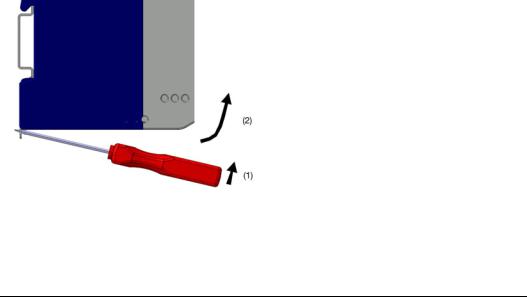
3.4Dismantling
h Insert a screwdriver into the release lug from below and lift up (1).
h Simultaneously swivel the screwdriver and case up out of the DIN rail (2).
2014-05-01 |
3 Installation 19 |
2014-05-01 |
3 Installation 20 |
3.5Electrical isolation
(1) Analog inputs
(3) Binary input
(5)Setup interface
(6)Display
(7)Analog output
(8)Power supply
50 V DC 3700 V AC
(1) »
»  »
»  (2)
(2)
(3)
 3700 V AC
(5) |
» |
(4) |
|
||
(6) |
|
|
(7) |
|
|
» |
3700 V AC |
||
|
|
|
|
|
|
|
|
(8) |
|
|
|
(2) Relay output "Alarm"
(4) Relay output "Pre-alarm"
3.6Use of the setup interface
-The setup interface USB is only designed for service use for a limited period, e.g. for transmitting setup data and during commissioning.
-It is not suitable for operation in a fixed installation for an unlimited period as the monitoring function is switched off du ring
data transmission with the setup program.
4 Electrical connection
4.1Installation notes
aCheck that the safety temperature limiter is correctly installed for its application (temperature measurement) and is operated within the admissible system parameters.
aThe device is designed for installation in switch cabinets, machines/plants or systems. Ensure that the customer's fuse rating does not exceed 20 A.
a Isolate the device at all poles prior to starting service or repair work.
aAll incoming and outgoing lines without a connection to the power supply network must be laid with shielded and twisted lines. Connect the screen on the device side to ground.
a Do not run input and output lines close to current-carrying components or cables.
a Do not connect any additional consumers to the screw terminals for the device power supply.
aThe choice of cable, the installation and the electrical connection of the device must conform to the requirements of VDE 0100 "Regulations on the Installation of Power Circuits with Nominal Voltages below 1000 V" or the appropriate local regulations.
aProtect the relay circuit by suitable measures.
The maximum contact rating is 230 V/3 A (ohmic load).
aThe electromagnetic compatibility conforms to the standards and regulations cited in the technical data. v Chapter 8 "Technical data"
a During commissioning we recommend carrying out a trial run of the system until temperature switch-off at the set limit.
Only allow qualified electricians to carry out the electrical connection and the configuration settings until commis- V sioning.
2014-05-01 |
4 Electrical connection 21 |
2014-05-01 |
4 Electrical connection 22 |
The approval according to DIN EN 14597 is only valid when the correct probe with DIN approval is set in the config- A uration level and also connected.
The limit value to be monitored must be within the admissible temperature range of the DIN probe. v Chapter 8.12 "Probes for the operating medium air"
v Chapter 8.13 "Probes for the operating medium water and oil"
The monitoring function is deactivated during data transmission using the setup program. v Chapter 12 "What to do, if ..."
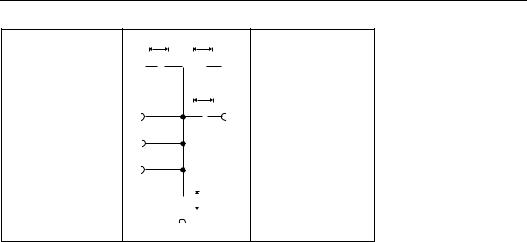
4.2 Connection diagram
Connection is carried out via screw terminals. |
Lead |
Admissible cross sec- |
|
|
tion |
|
1 wire |
≤ 2.5 mm2 |
|
fine-strand, |
≤ 1.5 mm2 |
|
with core-end ferrule |
|
|
|
|
|
|
|
|
|
|
2014-05-01 |
4 Electrical connection 23 |
2014-05-01 |
|
4 Electrical connection |
|
|
|
|
24 |
|||||||||||||||
|
|
|
|
|
|
|
|
|
|
|
|
|
|
|
|
|
|
|
|
|||
|
|
|
|
|
|
|
|
|
|
|
|
|
|
|
|
|
|
|
|
|||
Legend Remark |
|
Screw terminals |
|
|
|
Screw terminals |
|
|
|
|||||||||||||
|
|
|
|
|
|
|
|
|
|
|
|
|
|
|
|
|
|
|||||
1, 2 |
|
|
Analog input1 (E1) |
|
Analog input2 (E2) |
|||||||||||||||||
|
|
|
|
|
|
|
|
|
|
|
|
|
|
|
|
|
|
|
|
|
|
|
|
Thermocouple/ |
|
|
|
|
|
|
|
|
|
|
|
|
|
|
|
|
|
|
|
|
|
|
double thermocouple |
|
|
|
|
|
|
|
|
|
|
|
|
|
|
|
|
|
|
|
|
|
|
|
|
2 |
3 |
|
|
|
|
7 |
|
|
8 |
|
|
|
|||||||
|
|
|
|
|
|
|
|
|
|
|
|
|
|
|
|
|
|
|
|
|
|
|
|
RTD temperature probe Pt100/Pt1000 in |
|
|
|
|
|
|
|
|
|
|
|
|
|
|
|
|
|
|
|
|
|
|
2-wire circuit |
|
|
|
|
|
|
|
|
|
|
|
|
|
|
|
|
|
|
|||
|
|
|
|
|
|
|
|
|
|
|
|
|
|
|
|
|
|
|||||
|
|
|
|
|
|
|
|
|
|
|
|
|
|
|
|
|
|
|
|
|
|
|
|
|
|
1 |
|
|
|
|
3 |
|
|
6 |
|
|
|
|
|
|
|
8 |
|
||
|
|
|
|
|
|
|
|
|
|
|
|
|
|
|
|
|
|
|
|
|||
|
|
|
|
|
|
|
|
|
|
|
|
|
|
|
|
|
||||||
|
Enter the lead resistance for RTD temperature probes in two-wire circuit when using greater line |
|
|
|
||||||||||||||||||
|
A lengths. |
|
|
|
|
|
|
|
|
|
|
|
|
|
|
|
|
|
|
|||
|
v |
Setup program: edit => analog inputs |
|
|
|
|
|
|
|
|
|
|
|
|
|
|
|
|
|
|
||
|
|
|
|
|
|
|
|
|
|
|
|
|
|
|
|
|
|
|
|
|
||
|
RTD temperature probe Pt100/Pt1000 |
|
|
|
|
|
|
|
|
|
|
|
|
|
|
|
|
|
|
|
|
|
|
in three-wire circuit |
|
|
|
|
|
|
|
|
|
|
|
|
|
|
|
|
|
|
|
||
|
|
|
|
|
|
|
|
|
|
|
|
|
|
|
|
|
|
|
||||
|
|
|
1 |
|
2 |
|
3 |
|
|
|
6 |
|
|
|
7 |
8 |
||||||
|
|
|
|
|
|
|
|
|
|
|
|
|
|
|
|
|
|
|
|
|
|
|
|
RTD temperature probe Pt100 in |
|
|
|
|
|
|
|
|
|
|
|
|
|
|
|
|
|
|
|
|
|
|
two-wire circuit, individual probe for both analog |
|
|
|
|
|
|
|
|
|
|
|
|
|
|
|
|
|
|
|
|
|
V inputs |
|
|
|
|
|
|
|
|
|
|
|
|
|
|
|
|
|
|
|
|
|
|
|
|
|
|
|
|
|
|
1 |
|
3 |
6 |
8 |
|
|
|
|
|
|
|
|
|
|
|
|
|
|
|
|
|
|
|
|
|
|
|
|
|
|
|
|
|
|
|
|
|
Caution:
When only one probe (SIL2) is connected, the temperature limitation device
is reduced from SIL3 to SIL2. However, the internal 2-channel structure (1oo2D) in the device is still retained. Both channels measure the same probe due to the simplified external circuit.
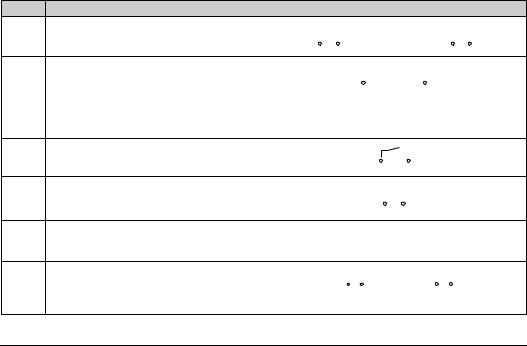
Legend
V
4
5
V
9
Remark |
Screw terminals |
|
Screw terminals |
||||||
4 to 20 mA |
+ |
– |
|
+ |
– |
||||
|
|
Ix |
|
|
|
|
|
Ix |
|
|
2 |
3 |
|
|
7 |
8 |
|||
4 to 20 mA for both analog inputs |
|
+ |
|
– |
|
|
|||
|
|
|
|
|
Ix |
|
|
|
|
|
|
|
|
|
|
|
|
||
|
|
2 |
7 |
|
|
||||
|
|
|
|
|
|
|
|
|
|
Caution:
When only one probe (SIL2) is connected, the temperature limitation device
is reduced from SIL3 to SIL2. However, the internal 2-channel structure (1oo2D) in the device is still retained. Both channels measure the same current signal due to the simplified external circuit.
Binary input |
|
|
|
|
|
|
|
|
|
|
|
|
|
|
|
|
Connection to a potential-free contact |
Ground |
4 |
|
|
|
|
|
|
|
|
|
|
|
|||
|
|
|
|
|
|
|
|
|
|
|
||||||
|
|
|
5 |
|
|
|
|
|||||||||
|
|
|
|
|
|
|
|
|
|
|
||||||
Analog output: |
|
|
|
|
|
– |
+ |
|
|
|
|
|
||||
0 to 20 mA |
|
|
|
|
|
|
|
|
|
|
|
|
||||
|
|
|
|
|
|
|
Ix,Ux |
|
|
|
|
|
|
|||
4 to 20 mA (ex-factory) |
|
|
|
|
|
|
|
|
|
|
|
|
|
|
|
|
|
|
|
|
|
|
|
|
|
|
|
|
|
|
|
|
|
0(2) to 10V |
|
|
|
|
|
9 |
10 |
|
|
|
|
|
||||
Caution |
|
|
|
|
|
|
|
|
|
|
|
|
|
|
|
|
The analog output is not part of the safety func- |
|
|
|
|
|
|
|
|
|
|
|
|
|
|
|
|
tion! |
|
|
|
|
|
|
|
|
|
|
|
|
|
|
|
|
Voltage supply |
AC: |
|
|
|
|
|
|
DC: |
|
|
|
|
||||
|
|
|
|
|
|
|
|
|
|
|||||||
according to rating plate |
L1 Line conductor L1 |
N |
|
|
|
|
(L+) |
L+ |
L- |
|||||||
|
N Neutral |
|
|
|
|
|
|
|
(L-) |
|
|
|
|
|||
|
|
|
|
|
|
|
|
|
|
|
|
|||||
|
|
|
|
|
|
|
|
|
|
|
|
|
|
|
|
|
|
L1 |
N |
|
|
|
|
|
|
|
|
L+ |
L- |
||||
|
|
|
|
|
|
|
|
|
|
|
|
|
|
|
|
|
2014-05-01 |
4 Electrical connection 25 |
2014-05-01 |
4 Electrical connection 26 |
|
|
|
|
Legend Remark |
Screw terminals |
Screw terminals |
|
|
|
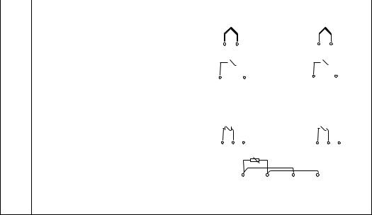
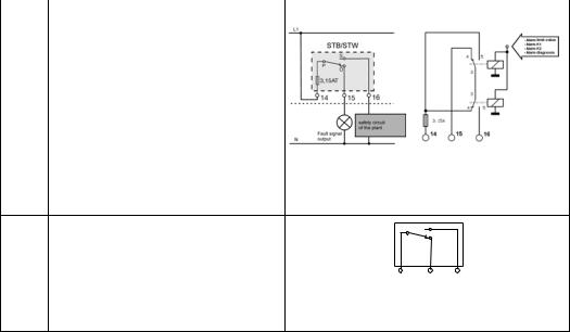
10Relay output "Alarm" (current-free state)
Relay (changeover contact element) with fuse cutout
Internal circuitry
11 |
Relay output for pre-alarm (KV) |
|
S |
|
Changeover contact |
|
|
|
P |
|
|
|
|
Ö |
|
|
|
|
11 12 13
|
Caution |
V |
The pre-alarm relay outputis not part of the |
|
safety function! |
5 Commissioning the device
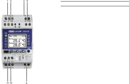
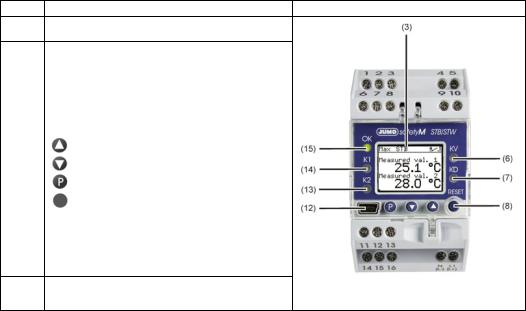
5.1Display and operating elements
hConnect the voltage supply - a test routine will start during which all LEDS will flash and the display with background lighting will indicate white pixels for 2 seconds and black pixels for 2 seconds.
Once the test routine has been completed, the device will indicate the main measured value (factory set). v If an alarm or error message appears, refer to Chapter 10 "Alarm messages".
5.2Setting the display after switch-on
v Chapter 7.6.4 "Normal display"
The screen is factory set to show the main measured value in German. The example shows the screen layout of a safety temperature limiter monitoring a maximum value of 29.6°C with a pre-alarm set to 9.9°C.
H |
If the main measured value is within the hysteresis during "Power ON", the relay outputs "Pre-alarm" and "Alarm" |
|||||||||
|
|
are deactivated. |
|
|
|
|
|
|
|
|
1 |
Switching behavior |
(1) |
(2) |
(3) |
|
|
2 Device function |
|
||
|
|
|
|
|
3 Binary input |
|
||||
|
|
|
|
|
|
|
|
|
|
|
7 |
Main measured value |
(7) |
|
|
|
|
|
|
|
|
|
|
|
|
|
|
|
||||
|
|
|
|
|
|
|
|
|
|
|
6 Pre-alarm |
|
|
|
|
|
(4) |
4 Temperature unit |
|
||
(6) |
|
|
|
|
|
|
||||
|
|
|
|
|
|
|
|
|
|
|
5 |
Limit value |
(5) |
|
|
|
|
|
|
|
|
|
|
|
|
|
|
|
|
|
|
|
|
|
|
|
|
|
|
|
|
|
|
2014-05-01 |
|
|
|
5 Commissioning the device |
27 |
|||||
2014-05-01 |
5 Commissioning the device 28 |
Legend Remark
3LCD display
Black and white with background lighting 96 x 64 pixels
6 |
LED KV (yellow) |
|
|
Is lit if the pre-alarm was triggered. |
|
|
|
|
7 |
LED KD (yellow) |
|
|
Is lit if the diagnosis processor has switched off a compo- |
|
|
nent. |
|
|
|
|
8 |
Keys |
|
|
(Can only be operated when the transparent hood is fold- |
|
|
ed up) |
|
|
Increase value / previous parameter |
|
|
Reduce value / next parameter |
|
|
Programming |
|
|
RESET |
|
|
|
|
12 |
Setup interface |
|
|
|
|
13 |
LED K2 (red) |
|
|
Is lit for all errors. |
|
|
|
|
14 |
LED K1 (red) |
|
|
Is lit for all errors. |
|
15LED OK
Green: OK range OFF: Error occurred
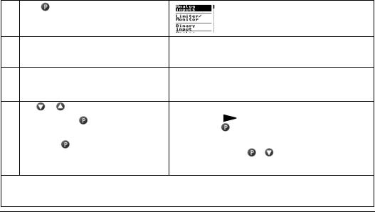
5.3Selecting and editing parameters (plausibility inquiry for input values)
The values are displayed in the standard display.
Carry out steps 1 to 4 to edit a value, e.g. in this case, the limit value
1 |
Press |
The first menu item "Analog inputs" has a black |
|
|
background. The vertical line on the right shows |
|
|
the current position. |
2Select limiter/monitor with  Use
Use  to change to the submenu
3Press 2x until the limit value appears Press
  (limit value flashes)
4 |
Use |
or |
to set the desired value |
|
|
Limit value flashes in du- |
||
|
Acknowledge with |
|
|
|
||||
|
(limit value is shown in duplicate) |
|
|
plicate on the display as a |
||||
|
|
|
||||||
|
|
|
control. |
|||||
|
|
|
|
|
|
|
||
|
|
|
|
|
|
|
|
|
5 |
Briefly press |
to confirm the value. |
|
|
|
|
||
|
The value is applied and saved. |
Use |
+ |
to return to the standard display |
||||
|
|
|
|
|
or menu topic "Back" or |
|||
|
|
|
|
|
return automatically after a timeout |
|||
HIf no key is pressed, the device automatically returns tothe standard display after 30 seconds (timeout) and the value is not saved. The length of the timeout is configurable.
v see operating overview on the first inner page of this manual.
2014-05-01 |
5 Commissioning the device 29 |

2014-05-01 |
5 Commissioning the device 30 |
5.4Aborting edit
 +
+  are used to abort editing and retain the previous value.
5.5Alarm acknowledgement using the Reset key (only for temperature limiters STB)
h Press  key and hold down
Ticks appear
after the errors The alarm is no longer pending and is acknowledged as soon as the time bar has finished (3 seconds).
A bell is
shown after The alarm condition is still pending and cannot be acknowledged. the error.
5.6Alarm acknowledgement via binary input (only for temperature limiters STB)
The binary input can be configured so that, for example, alarms can be unlocked via a potential-free contact. The function only reacts to the switching flank from the "open" to the "closed" state.
The contact then behaves in the same way as the "Reset" button. v Chapter 7.4.1 "Function"
Loading...