

Page 1

DDL-900B
INSTRUCTION MANUAL
Page 2

CONTENTS
I. SPECIFICATIONS ........................................................................................ 1
II. SET-UP ........................................................................................................ 3
1. Installation ......................................................................................................................................... 3
2. Installing the pedal sensor ...............................................................................................................4
3. Installing the power switch (for CE) ................................................................................................ 4
4. Connecting the connector ...............................................................................................................5
5. How to install the power plug .......................................................................................................... 6
6. Attaching the connecting rod ..........................................................................................................6
7. Winding the bobbin thread ..............................................................................................................7
8. Adjusting the height of the knee lifter ............................................................................................. 8
9. Installing the thread stand ...............................................................................................................8
10. Lubrication ........................................................................................................................................9
11. Adjusting the amount of oil (oil splashes) .................................................................................... 10
12. Attaching the needle .......................................................................................................................12
13. Setting the bobbin into the bobbin case ......................................................................................13
14. Adjusting the stitch length .............................................................................................................13
15. Presser foot pressure ..................................................................................................................... 13
16. Hand lifter ........................................................................................................................................13
17. Adjusting the height of the presser bar ........................................................................................ 14
18. Threading the machine head .........................................................................................................14
19. Thread tension ................................................................................................................................15
20. Thread take-up spring ....................................................................................................................15
21. Adjusting the thread take-up stroke .............................................................................................15
22. Needle-to-hook relationship ..........................................................................................................16
23. Height of the feed dog .................................................................................................................... 16
24. Tilt of the feed dog .......................................................................................................................... 17
25. Adjusting the feed timing ...............................................................................................................17
26. Counter knife ................................................................................................................................... 18
27. Pedal pressure and pedal stroke ...................................................................................................18
28. Adjustment of the pedal .................................................................................................................19
29. Marker dots on the handwheel ......................................................................................................19
III. FOR THE OPERATOR ............................................................................. 20
1. Operating procedure of the sewing machine ............................................................................... 20
2. Setting procedure of the machine head .......................................................................................21
3. Operation panel built in the machine head ..................................................................................22
4. Operating procedure of the sewing pattern .................................................................................23
5. One-touch setting ...........................................................................................................................25
6. Setting of functions ........................................................................................................................26
7. Production support function .........................................................................................................27
8. Setting of thread clamp (NB type only) .........................................................................................29
9. Function setting list ........................................................................................................................ 31
10. Detailed explanation of selection of functions ............................................................................35
11. Automatic compensation of neutral point of the pedal sensor .................................................. 45
12. Selection of the pedal specications ............................................................................................ 46
13. Setting of the auto lifter function ..................................................................................................46
14. Selecting procedure of the key-lock function .............................................................................. 47
15. Initialization of the setting data .....................................................................................................47
16. LED hand light .................................................................................................................................48
17. Height adjustable one-touch type reverse stitching switch ....................................................... 48
IV. MAINTENANCE ....................................................................................... 49
1. Adjusting the machine head ..........................................................................................................49
2. Error codes ...................................................................................................................................... 50
i
Page 3

I. SPECIFICATIONS
Supply voltage Single phase 220V/230V/240V
Frequency 50Hz/60Hz
Operating environment
Input 210VA
Temperature : 5 to 35˚C
Humidity 35 - 85 %
DDL-900B-
S : Light- to Medium-weight materials
H : Heavy-weight materials
DDL-900B-S DDL-900B-H
Application
Max. sewing speed 5,000 sti/min 4,000 sti/min
Thread trimming speed 210 sti/min 210 sti/min
Stitch length 4 mm 5 mm
Presser foot lift (by knee lifter) 13 mm 13 mm
Needle
Lubricating oil JUKI CORPORATION GENUINE OIL 7
Noise
*1
Light- to Medium-weight materials Heavy-weight materials
DB × 1 (#14) #9 to 18, 134 (Nm 90) Nm
65 to 110 (for CE)
- Equivalent continuous emission
sound pressure level (LpA) at the
workstation :
A-weighted value of 81.0 dB; (Includes
KpA = 2.5 dB); according to ISO
10821- C.6.2 -ISO 11204 GR2 at
4,000 sti/min.
A-weighted value of 80.0 dB; (Includes
KpA = 2.5 dB); according to ISO
10821- C.6.2 -ISO 11204 GR2 at
3,500 sti/min.
- Equivalent continuous emission
sound pressure level (LpA) at the
workstation :
A-weighted value of 83.0 dB; (Includes
KpA = 2.5 dB); according to ISO
10821- C.6.2 -ISO 11204 GR2 at
4,000 sti/min.
A-weighted value of 80.0 dB; (Includes
KpA = 2.5 dB); according to ISO
10821- C.6.2 -ISO 11204 GR2 at
3,500 sti/min.
DB x 1 (#21) #20 to 23
• The sewing speed preset at the time of shipping : 4,000 sti/min
*1 : Needle used depends on the destination.
– 1 –
Page 4
C
H
G
E
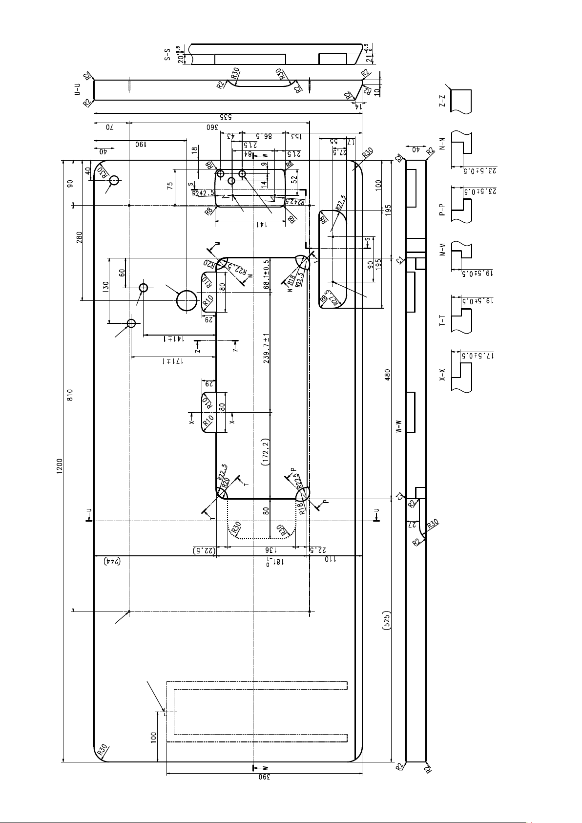
DRAWING OF TABLE
J
D
F
I
A
B
– 2 –
drilled hole
4xø3.4 on the bottom surface, depth 20 (Drill a hole at the time of set-up.)
Installing position of drawer stopper (on the reverse side)
ø18 drilled hole
3xø13 drilled hole
2xø3.5, depth 10
2xø3.5, depth 10
ø40±0.5
ø16 depth 30
ø16 depth 30 (for optional parts)
A
B
C
D
E
F
C1.5 to C2.5 (hinge side only)
G
H
I
J
Page 5

II. SET-UP
1. Installation
D
1) Carry the sewing machine with two persons as
shown in the gure above.
Do not hold the handwheel D.
C
❸
❶
❷
❽
❶
A B
❹
❾
❸
❶
19.5 mm23.5 mm
❸
2) Do not put protruding articles such as the screw-
driver and the like at the location where the
sewing machine is placed.
3) Adjust so that the underside cover is supported at
the four corners of the table. Mount rubber hinge
seat ❽ on the table and x it on the table with a
nail.
4) Two rubber seats ❶ for supporting the head por-
tion on the operator side A are xed on the extended portion of the table by hitting the nail ❷ ,
and the other two rubber cushion seats ❸ on the
hinge side B are xed by using a rubber-based
adhesive. Then, underside cover ❹ is placed.
❼
5) Fit hinge ❼ into the opening in the machine bed,
and t the machine head to table rubber hinge ❽
before placing the machine head on cushions ❾
on the four corners.
6) Securely t machine head support stand ❻ in
the hole (60 x 141 x ø16, depth 30) (refer to H in
DRAWING OF TABLE p. 2) in the table.
❽
❻
1. Be sure to install the machine head support rod ❻ supplied with the unit.
2. If a pair of scissors or the like is caught between the control box and the table, the control box
cover can break. To prevent such an accident, do not place anything on C section.
3. Be aware that the control box breakage and/or oil leakage can occur if operating the sewing
machine with the machine head support rod ❻ removed.
❼
– 3 –
Page 6

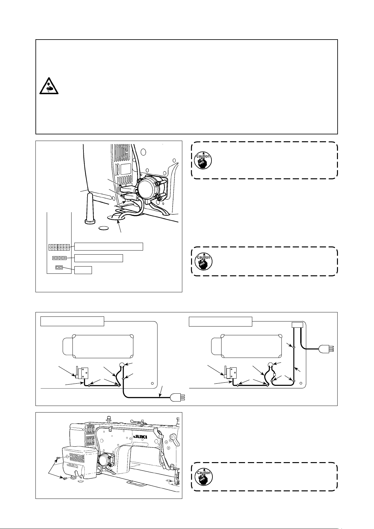
2. Installing the pedal sensor
❶
3. Installing the power switch (for CE)
WARNING :
1. Be sure to attach the ground wire (green/yellow) to the specied location (on the ground side).
2. Take care not to allow terminals to come in contact with each other.
3. When closing the power switch cover, take care not to allow the cord to be caught under it.
1) Install the pedal sensor to the table with mounting
screws ❶ supplied with the unit.
It is necessary to install the pedal sensor at such
a position that the connecting rod is perpendicu-
lar to the table.
2) After the completion of installation of the pedal
sensor on the table, place the sewing machine
head on the table.
❷
1ø 220V-240V
❹
Blue Blue
❶
Do not insert the power plug into the plug
receptacle.
1
) Remove screw ❶ on the side face of the power
switch cover to open the power switch cover.
2) Pass AC input cord ❷(40145128),
❸(M6102461DAA) through the rear face of the
power switch. Bundle the cord with cable clip
band ❹ to secure it.
3) Securely x the terminals of the AC input cord
❷(40145128), ❸(M6102461DAA) by tightening
the screws at the specied locations.
4) Close the power switch cover. Tighten screw ❶
on the side face of the power switch cover.
❷
Green/
Yellow
Green/
Yellow
❸
Brown Brown
– 4 –
Page 7
4. Connecting the connector
WARNING :
• To protect against personal injury resulting from abrupt start of the sewing machine, be sure to
turn the power OFF, unplug the machine and wait for ve minutes or more before installing the
pedal sensor.
• To prevent damage of device caused by maloperation and wrong specications, be sure to connect
all the corresponding connectors to the specied places. (If any of the connectors is inserted into
a wrong connector, not only the device corresponding to the connector can break but also it can
start abruptly, inviting the risk of personal injury.)
• To prevent personal injury caused by maloperation, be sure to lock the connector with lock.
• Do not connect the power plug until the connection of cords is completed.
• Fix the cords while taking care not to forcibly bend them or excessively clamp them with staples.
• As for the details of handling respective devices, read carefully the Instruction Manuals supplied
with the devices before handling the devices.
❸
❷
❶
❹
Machine head connector
AC power supply
Pedal
Connector connection diagram
Do not insert the power plug into the wall
outlet.
Check to be sure that the power switch is
turned OFF.
1) Connect the connectors listed below to the con-
trol box in the order of ❶ to ❸.
❶ Pedal sensor cable
❷ AC input cable
❸ Machine head connector
For the connection ports of the cables, refer to
the connector layout drawing.
Be sure to fully insert the connectors into
the corresponding ports until they are
locked.
2) Draw out cable of the control box through cable
draw-out hole ❹ to route it to the underside of
the sewing machine table.
Underside of the table
Pedal sensor
❶
❻
Slack
❺
❹
❺
❷
Underside of the table
❺
Pedal sensor
❶
Slack
❺
(For CE)
❹
❺
❷
3) Fix pedal sensor cable ❶ and AC input cable ❷
with a staple ❺.
4) Attach the solenoid cover with two solenoid cover
setscrews ❻ which are supplied with the unit as
accessories.
Take care not to allow the cords to be
caught under the cover when attaching
the cover.
– 5 –
Page 8
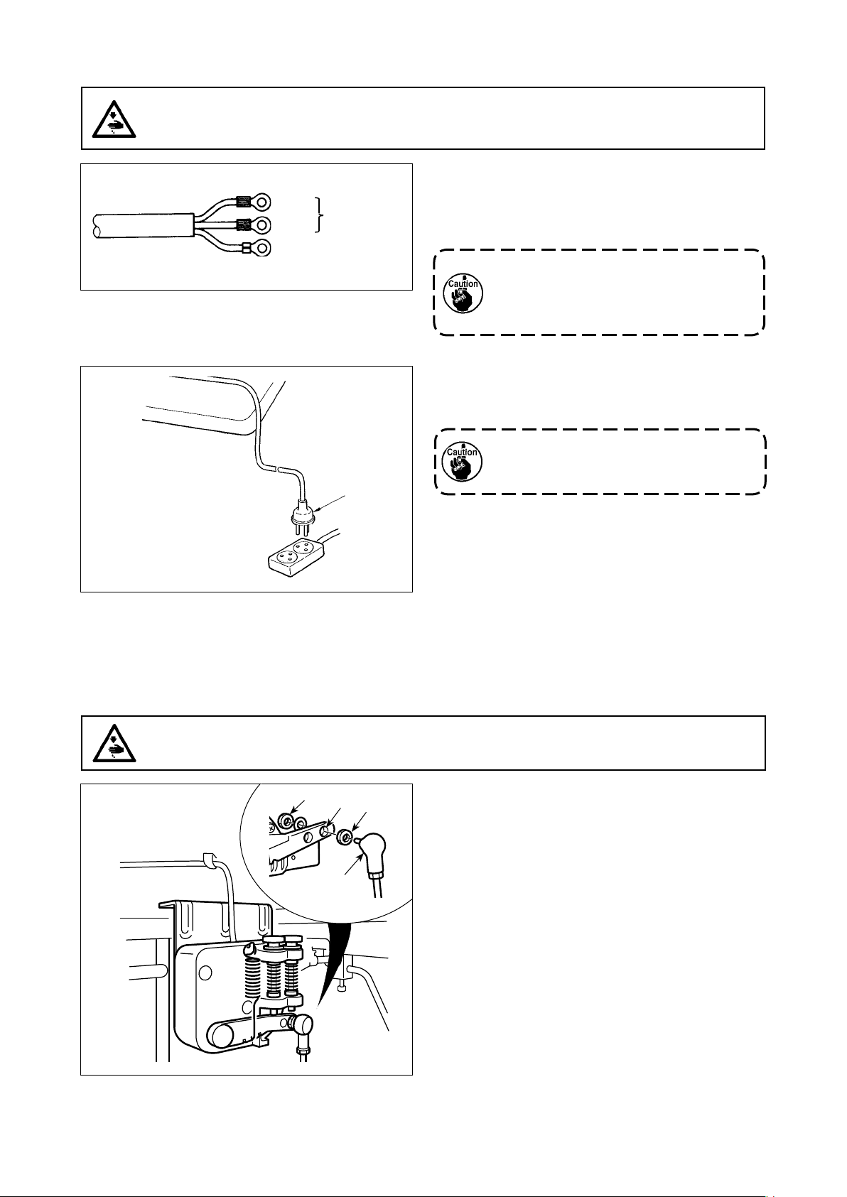
5. How to install the power plug
WARNING :
1. Be sure to attach the ground wire (green/yellow) to the specied location (on the ground side).
2. Take care not to allow terminals to come in contact with each other.
1ø 220-240V
Blue
Brown
Green / Yellow
(ground wire)
AC 220-240V
❶
1) Connect the power cord to power plug ❶. Con-
nect the blue and brown wires (1ø) to the power
supply side and the green/yellow wire to the earth
side as illustrated in the gure.
1. Be sure to prepare the power plug ❶
which conforms to the safety standard.
2. Be sure to connect the ground lead
(green/yellow) to the grounding side.
2) Check that the power switch is in the OFF state.
Then, insert the power plug ❶ coming from the
power switch into the plug receptacle.
In prior to the connection of the power
plug ❶, re-check the supply voltage spec-
ication indicated on the control box.
* The power plug ❶ is different in shape ac-
cording to the destination of the sewing
machine.
6. Attaching the connecting rod
WARNING :
To protect against possible personal injury due to abrupt start of the machine, be sure to start the
following work after turning the power off and a lapse of 5 minutes or more.
❸
❶
❷
❸
Fix connecting rod ❶ to installing hole of pedal lever
❷ with nut ❸.
– 6 –
Page 9
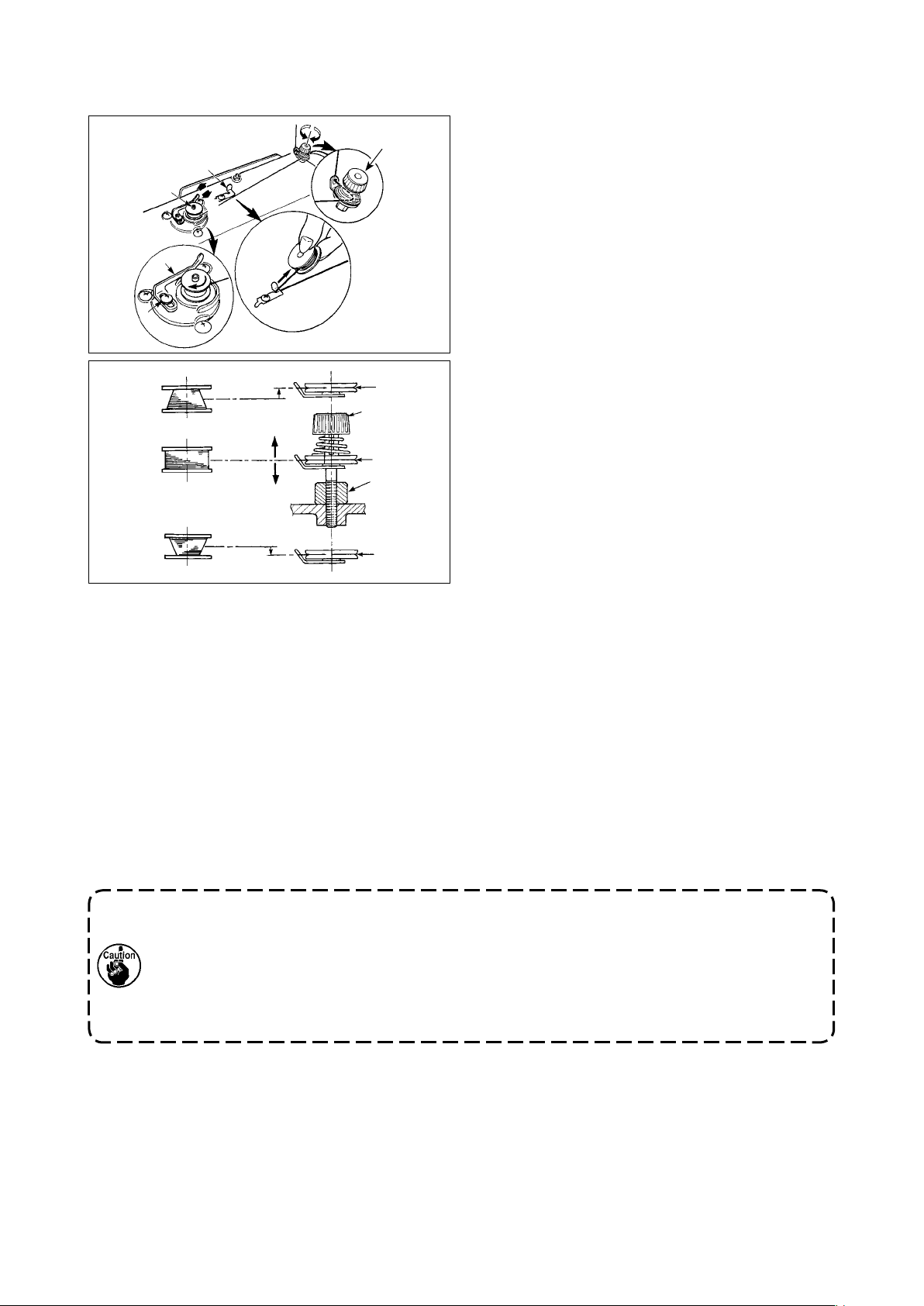
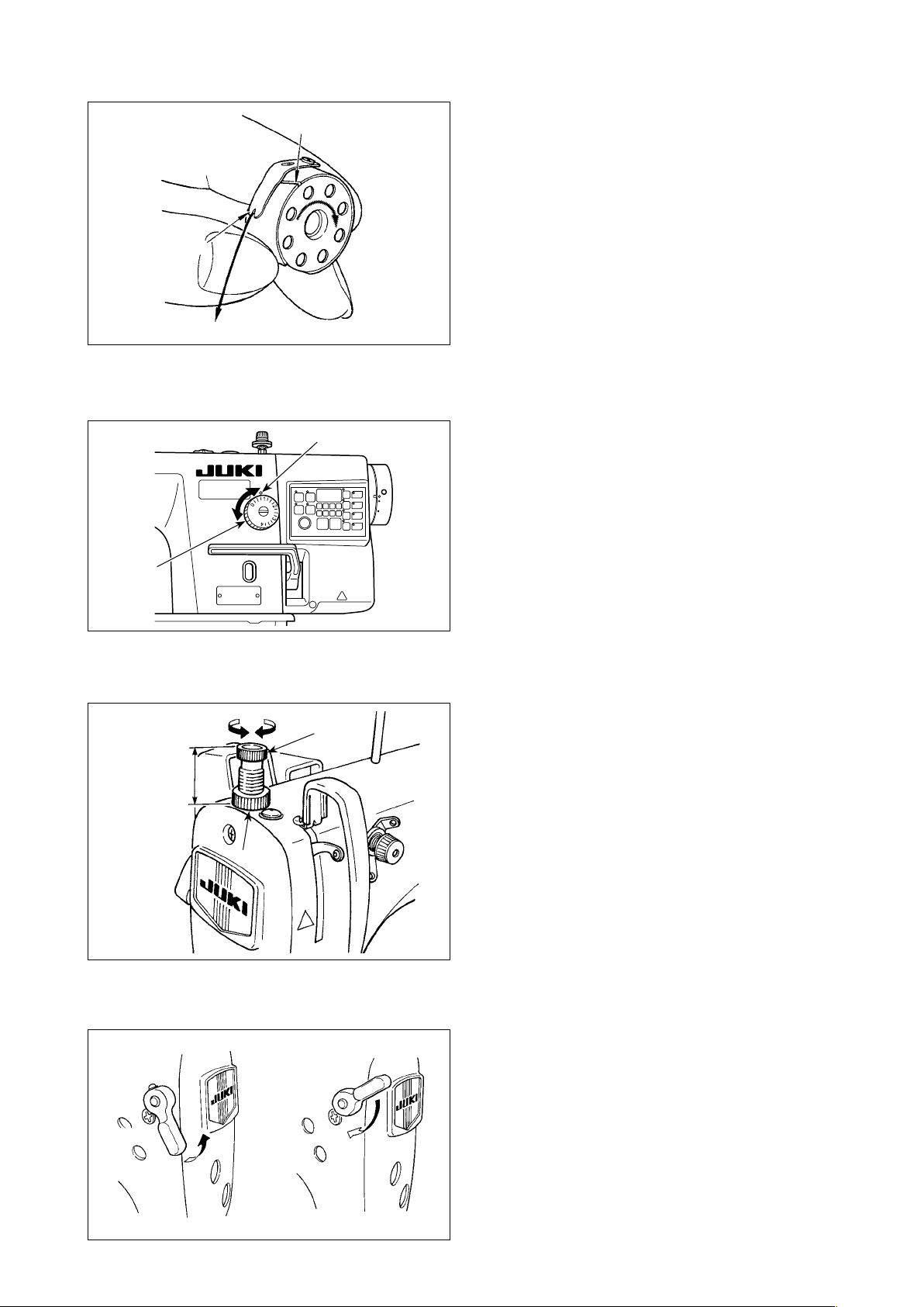
7. Winding the bobbin thread
1) Insert the bobbin deep into the bobbin winder
❽
❸
B
❶
A
❷
❹
C
❻
❼
D
❻
❺
E
❻
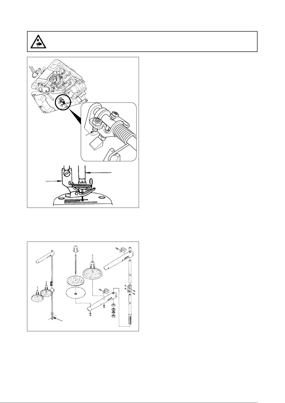
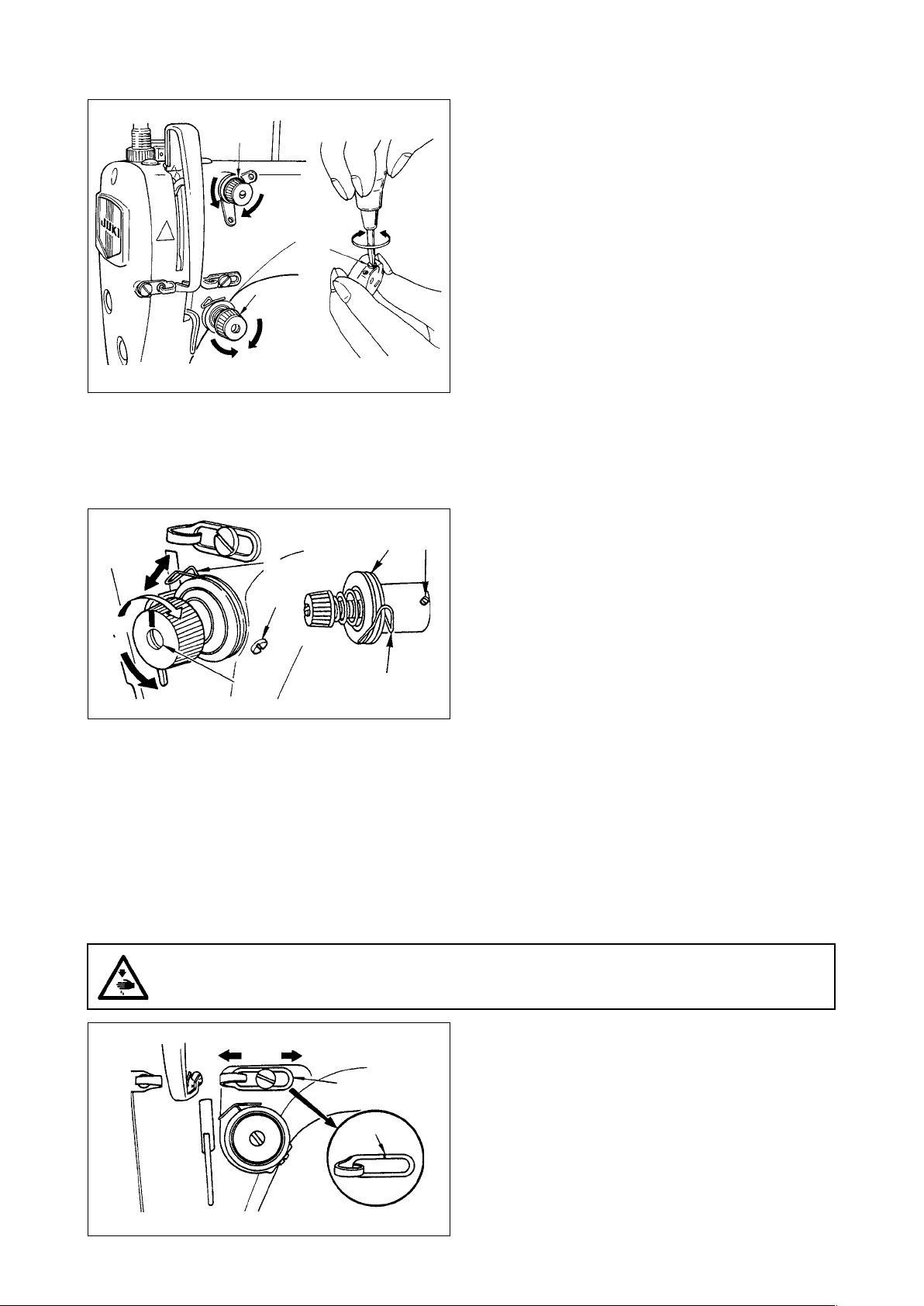
6) In case that the bobbin thread is not wound evenly on the bobbin, loosen screw ❺ and adjust the height
of bobbin thread tension ❽.
• It is the standard that the center of the bobbin is as high as the center of thread tension disk ❻.
• Adjust the position of thread tension disk ❻ to the direction of D when the winding amount of the bobbin
thread on the lower part of the bobbin is excessive and to the direction E when the winding amount of
the bobbin thread on the upper part of the bobbin is excessive.
After the adjustment, tighten screw ❺.
7) To adjust the tension of the bobbin winder, turn the thread tension nut ❼.
spindle ❶ until it will go no further.
2) Pass the bobbin thread pulled out from the
spool rested on the right side of the thread stand
following the order as shown in the gure on the
left. Then, wind clockwise the end of the bobbin
thread on the bobbin several times.
(In case of the aluminum bobbin, after winding
clockwise the end of the bobbin thread, wind
counterclockwise the thread coming from the
bobbin thread tension several times to wind the
bobbin thread with ease.)
3) Press the bobbin winder trip latch ❷ in the direc-
tion of A and start the sewing machine. The bob-
bin rotates in the direction of C and the bobbin
thread is wound up. The bobbin winder spindle ❶
automatically as soon as the winding is nished.
4) Remove the bobbin and cut the bobbin thread
with the thread cut retainer ❸.
5) When adjusting the winding amount of the bobbin
thread, loosen setscrew ❹ and move bobbin
winding lever ❷ to the direction of A or B. Then
tighten setscrew ❹.
To the direction of A : Decrease
To the direction of B : Increase
1. When winding the bobbin thread, start the winding in the state that the thread between the
bobbin and thread tension disk ❻ is tense.
2. When winding the bobbin thread in the state that sewing is not performed, remove the needle
thread from the thread path of thread take-up and remove the bobbin from the hook.
3. There is the possibility that the thread pulled out from the thread stand is loosened due to
the inuence (direction) of the wind and may be entangled in the handwheel. Be careful of the
direction of the wind.
– 7 –
Page 10
8. Adjusting the height of the knee lifter
WARNING :
Be sure to turn the power OFF before the following work in order to prevent personal injury due to
unintentional starting of the sewing machine.
❶
1) The standard height of the presser foot lifted
using the knee lifter is 10 mm.
2) You can adjust the presser foot lift up to 13 mm
using knee lifter adjust screw ❶.
3) When you have adjusted the presser foot lift
to over 10 mm, be sure that the bottom end of
needle bar ❷ in its lowest position does not hit
presser foot ❸.
❸
9. Installing the thread stand
❷
1) Assemble the thread stand unit, and insert it in
the hole in the machine table.
2) Tighten nut ❶.
❶
– 8 –
Page 11
10. Lubrication
WARNING :
1. Do not connect the power plug until the lubrication has been completed so as to prevent accidents due to abrupt start of the sewing machine,
2. To prevent the occurrence of an inammation or rash, immediately wash the related portions if oil
adheres to your eyes or other parts of your body.
3. If oil is mistakenly swallowed, diarrhea or vomitting may occur. Put oil in a place where children
cannot reach.
❻
❷
❺
❹
A
❸
B
❶
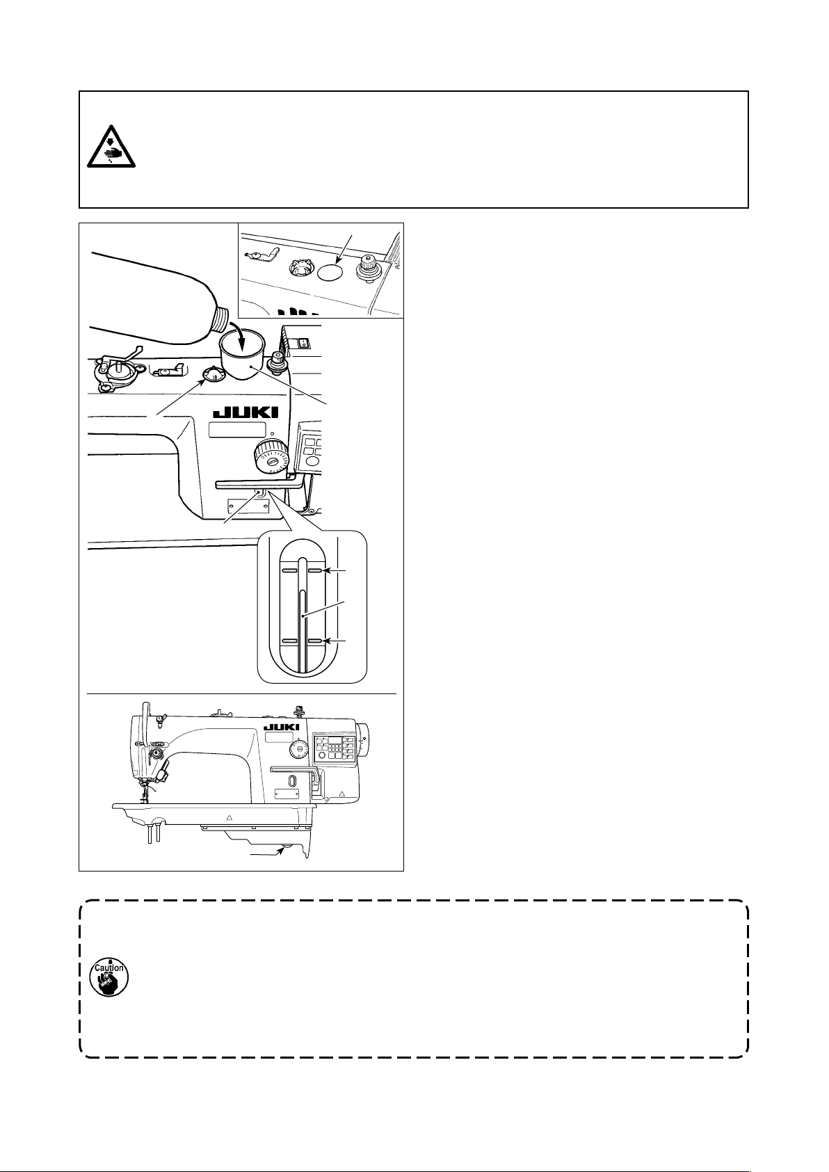
1) Before running the sewing machine, remove
rubber plug ❶ from the top of the machine arm,
and add oil through the oil inlet using accessory
funnel ❹ supplied with the sewing machine.
2) Fill the oil tank with the oil until the top end of
oil amount indicating rod ❸ comes between the
upper engraved marker line A and the lower
engraved marker line B of oil amount indicating
window ❷.
If the oil is lled excessively, it will lead from the
junction between the oil shield and bed, or from
the junction between the rubber plug and bed,
or proper lubrication will not be performed. So,
be careful. In addition, when the oil is vigorously
lled, it may overow from the oil hole. So, be
careful.
* When oil is added until MAX. line A is reached,
the oil quantity becomes 600 cc.
* Check the oil quantity while the sewing ma-
chine is at rest.
* Check the quantity of oil in the oil tank by view-
ing the oil surface from the side of oil amount
indicating window ❷.
3) When you operate the sewing machine, rell oil if
the top end of oil amount indicating rod ❸ comes
down to the lower engraved marker line B of oil
amount indicating window ❷.
4) When you operate the machine after lubrication,
you will see splashing oil through oil sight window
❻ if the lubrication is adequate.
* Note that the amount of the splashing oil is
unrelated to the amount of the lubricating oil.
1. When you use a new sewing machine or a sewing machine after an extended period of disuse, use the sewing machine after performing break-in at 2,000 sti/min or less.
2. For the oil lubrication, purchase JUKI CORPORATION GENUINE OIL 7 (Part No. :
MML007600CA).
3. Be sure to lubricate clean oil.
4. Be aware oil leakage can occur if the surface of added oil quantity exceeds MAX. line A.
5. Transporting the sewing machine with the sewing machine lled with oil can give rise to the
risk of oil leakage. Be sure to discharge oil from the sewing machine through drain cock ❺.
– 9 –
Page 12

11. Adjusting the amount of oil (oil splashes)
WARNING :
Be extremely careful about the operation of the machine since the amount of oil has to be checked
by turning the hook at a high speed.
(1) Conrmation of the amount of oil in the hook
Amount of oil (oil splashes) conrmation paper
①
25 mm
70 mm
Oil splashes conrmation paper
Position to conrm the amount of oil (oil splashes)
②
3 - 10 mm
Closely t the paper against the wall
surface of the bed.
* When carrying out the procedure described below in 2), remove the slide plate and take extreme caution
not to allow your ngers to come in contact with the hook.
1) If the machine has not been sufciently warmed up for operation, make the machine run idle for approxi-
mately three minutes. (Moderate intermittent operation)
2) Place the amount of oil (oil spots) conrmation paper under the hook immediately after the machine stops
running.
3) Check to be sure that the oil surface in the oil shield rests in the range between the "MAX. line" and the
"MIN. line".
4) Conrmation of the amount of oil should be completed in ve seconds. (Check the period of time with a
watch.)
(2) Adjusting the amount of oil (oil spots) in the hook
1) Tilt the sewing machine. Turn oil amount adjust-
ment screw ❶, which is mounted on the front
bushing of lower shaft, in the "+" direction (direc-
B
A
❶
tion A) to increase the oil amount (oil spots), or
in the "-" direction (direction B) to decrease it.
* The oil-amount +/- indication mark is shown on
2) After the amount of oil in the hook has been
properly adjusted with the oil amount adjustment
screw ❶, make the sewing machine run idle for
approximately 30 seconds to check the amount
of oil in the hook.
the underside cover.
– 10 –
Page 13
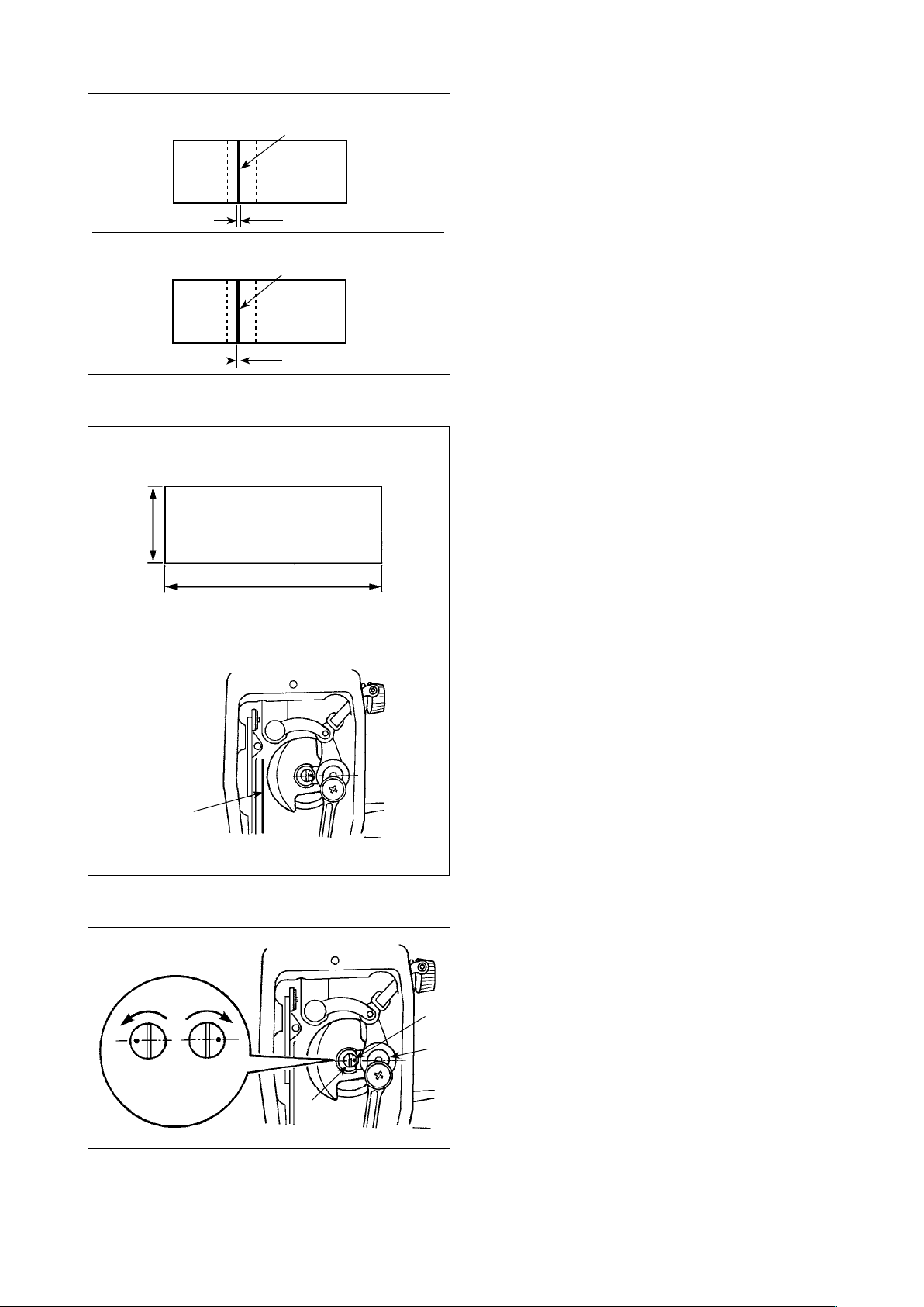
(3) Sample showing the appropriate amount of oil in the hook
Appropriate amount of oil (small)
Splashes of oil from the hook
1 mm
Appropriate amount of oil (large)
Splashes of oil from the hook
2 mm
1) The amount of oil shown in the samples on the
left should be nely adjusted in accordance with
sewing processes. Be careful not to excessively
increase/decrease the amount of oil in the hook.
(If the amount of oil is too small, the hook will be
seized (the hook will be hot). If the amount of oil
is too much, the sewing product may be stained
with oil.)
2) Check the oil amount (oil splashes) three times
(with three sheets of paper).
(4) Conrmation of the amount of oil supplied to the face plate parts
Amount of oil (oil splashes) conrmation paper
①
25 mm
70 mm
Position to conrm the amount of oil
②
(oil splashes)
Oil splashes
conrmation paper
* When carrying out the work described below in
2), remove the face plate and take extreme cau-
tion not to allow your ngers to come in contact
with the thread take-up lever.
1) If the machine has not been sufciently warmed
up for operation, make the machine run idle for
approximately three minutes. (Moderate intermit-
tent operation)
2) Place the amount of oil (oil spots) conrmation
paper under the hook immediately after the ma-
chine stops running.
3) Check to be sure that the oil surface in the oil
shield rests in the range between the "MAX. line"
and the "MIN. line".
4) The time required for the conrmation of the
amount of oil (oil splashes) should be completed
in ten seconds. (Measure the period of time with
a watch.)
(5) Adjusting the amount of oil supplied to the face plate parts
1) Adjust the amount of oil supplied to the thread
take-up and needle bar crank ❷ by turning adjust
C
Maximum
❶
Minimum
B
A
❷
❶
– 11 –
pin ❶.
2) The minimum amount of oil is reached when
marker dot A is brought close to needle bar
crank ❷ by turning the adjust pin in direction B.
3) The maximum amount of oil is reached when
marker dot A is brought to the position just
opposite from the needle bar crank by turning the
adjust pin in direction C.
Page 14
(6) Sample showing the appropriate amount of oil supplied to the face plate parts
Appropriate amount of oil (small)
S
plashes of oil from the thread take-up lever
1 mm
Appropriate amount of oil (large)
S
plashes of oil from the thread take-up lever
2 mm
1) The state given in the gure shows the appropri-
ate amount of oil (oil splashes). It is necessary to
nely adjust the amount of oil in accordance with
the sewing processes. However, do not exces-
sively increase/decrease the amount of oil in the
hook. (If the amount of oil is too small, the face
plate parts will be hot or seize. If the amount of oil
is too much, the sewing product may be stained
with oil.)
2) Check the oil amount (oil splashes) three times
(with three sheets of paper).
12. Attaching the needle
WARNING :
Be sure to turn the power OFF before the following work in order to prevent personal injury due to
unintentional starting of the sewing machine.
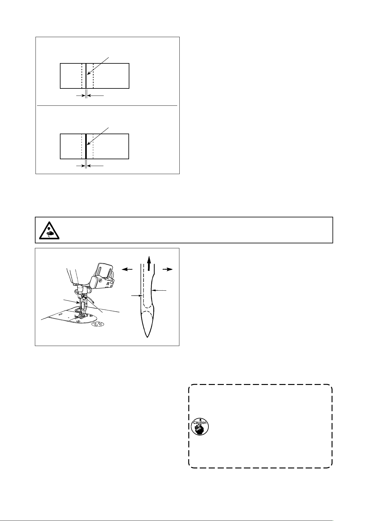
Use the specied needle for the machine. Use the
proper needle in accordance with the thickness of
❶
D B
A
C
❷
thread used and the kinds of the materials.
1) Turn the handwheel until the needle bar reaches
the highest point of its stroke.
2) Loosen screw ❷, and hold needle ❶ with its
indented part A facing exactly to the right in
direction B.
3) Insert the needle fully into the hole in the needle
bar in the direction of the arrow until the end of
hole is reached.
4) Securely tighten screw ❷.
5) Check that long groove C of the needle is facing
exactly to the left in direction D.
When polyester lament thread is used,
if the indented part of the needle is tilted
toward operator's side, the loop of thread
becomes unstable. As a result, hangnail
of thread or thread breakage may occur.
For the thread that such phenomenon
is likely to occur, it is effective to attach
the needle with its indented part slightly
slanting on the rear side.
– 12 –
Page 15
13. Setting the bobbin into the bobbin case
A
B
C
14. Adjusting the stitch length
A
1) Pass the thread through thread slit A, and pull
the thread in direction C. By so doing, the thread
will pass under the tension spring and come out
from notch B.
2) Check that the bobbin rotates in the direction of
the arrow when thread is pulled.
* The dial calibration is in millimeters (reference
value).
1) Turn stitch length dial ❶ in the direction of the
arrow, and align the desired number to marker
dot A on the machine arm.
❶
15. Presser foot pressure
AB
29 to 32 mm
❷
16. Hand lifter
❶
1) Loosen nut ❷. As you turn presser spring regulator ❶ clockwise (in direction A), the presser foot
pressure will be increased.
2) As you turn the presser spring regulator ❶ counter-clockwise (in direction B), the pressure will be
decreased.
3) After adjustment, tighten nut ❷.
The standard value of the pressure regulating thumb
screw is 29 to 32 mm.
1) The presser foot is lifted by moving the lever
upward.
2) The presser foot is lowered by moving the lever
downward.
– 13 –
Page 16
17. Adjusting the height of the presser bar
WARNING :
Be sure to turn the power OFF before the following work in order to prevent personal injury due to
unintentional starting of the sewing machine.
❶
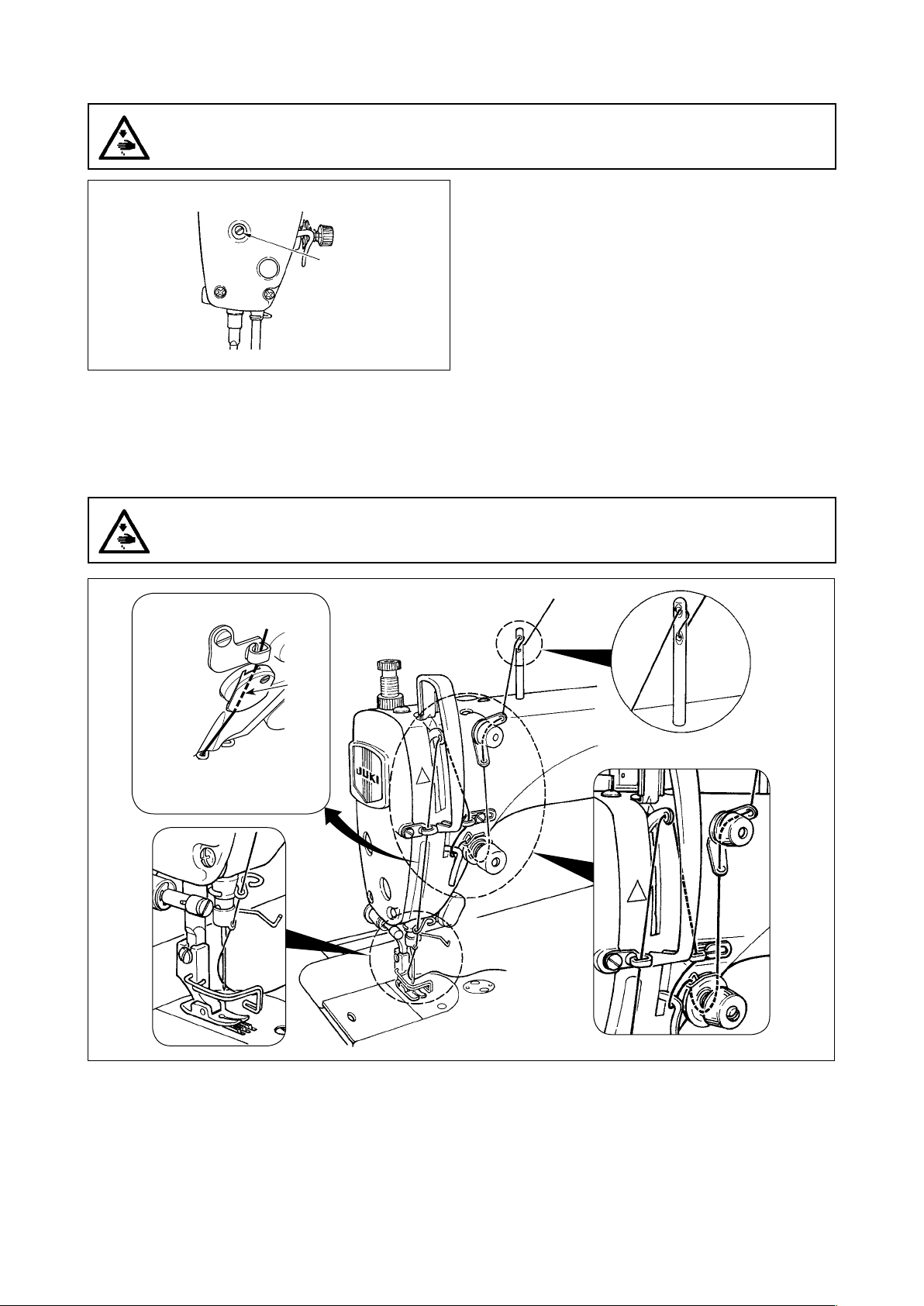
18. Threading the machine head
WARNING :
Be sure to turn the power OFF before the following work in order to prevent personal injury due to
unintentional starting of the sewing machine.
1) Loosen setscrew ❶, and adjust the presser bar
height or the angle of the presser foot.
2) After adjustment, securely tighten the setscrew
❶.
[NB type]
A
(Note)
Be sure to pass the thread
through the section A.
– 14 –
Page 17
19. Thread tension
❶
B
❷
A
❸
E
F
(1) Adjusting the needle thread tension
1) The length of thread remaining at the needle tip
after thread trimming is shortened by turning tension regulating nut No. 1 ❶ clockwise in direction
A.
2) It is lengthened by turning the nut counterclockwise in direction B.
3) The needle thread tension is increased by turning
tension regulating nut No. 2 ❷ clockwise in direction C.
4) It is decreased by turning the nut counterclockwise in direction D.
C
D
20. Thread take-up spring
❶
❷
A
B
❸
❶
❺
❹
(2) Adjusting the bobbin thread tension
1) The bobbin thread tension is increased by turning
tension regulating screw ❸ clockwise in direction
E.
2) It is decreased by turning the screw counterclockwise in direction F.
(1) Changing the stroke of thread take-up
spring ❶
1) Loosen setscrew ❷.
2) As you turn tension post ❸ clockwise (in direction A), the stroke of the thread take-up spring
will be increased.
3) As you turn tension post ❸ counterclockwise (in
direction B), the stroke will be decreased.
(2) Changing the pressure of thread take-up
spring ❶
1) Loosen setscrew ❷, and remove thread tension
asm. ❺.
2) Loosen setscrew ❹.
3) As you turn tension post ❸ clockwise (in direction A), the pressure will be increased.
4) As you turn the tension post ❸ counterclockwise
(in direction B), the pressure will be decreased.
21. Adjusting the thread take-up stroke
WARNING :
Be sure to turn the power OFF before the following work in order to prevent personal injury due to
unintentional starting of the sewing machine.
A
B
❶
C
1) When sewing heavy-weight materials, move
thread guide ❶ to the left (in direction A) to
increase the length of thread pulled out by the
thread take-up.
2) When sewing light-weight materials, move thread
guide ❶ to the right (in direction B) to decrease
the length of thread pulled out by the thread takeup.
3) Normally, thread guide ❶ is positioned in a way
that marker line C is aligned with the center of
the screw.
– 15 –
Page 18

22. Needle-to-hook relationship
WARNING :
Be sure to turn the power OFF before the following work in order to prevent personal injury due to
unintentional starting of the sewing machine.
❶
C
D
❸
A
❷
DDL-900B 0.04 to 0.10
If the clearance between the blade point
of hook and the needle is smaller than the
specied value, the blade point of hook
will be damaged. If the clearance is larger,
stitch skipping will result.
❹
E
B
Dimension F (mm)
A
B
❺
Adjust the timing between the needle and
the hook as follows :
1) Turn the handwheel to bright the needle bar
down to the lowest point of its stroke, and loosen
setscrew ❶.
Adjusting the needle bar height.
2) [For a DB/DP needles]
Align marker line A on the needle bar ❷ with the
bottom end of the needle bar lower bushing ❸,
then tighten clamping screw ❶ of the needle bar
F
connection.
[For a DA needle]
Align marker line C on the needle bar ❷ with the
bottom end of the needle bar lower bushing ❸,
then tighten clamping screw ❶ of the needle bar
connection.
Adjusting position of the hook ❺.
3) [For a DB/DP needles]
Loosen three setscrews of the hook, turn the
handwheel and align marker line B on ascending
the needle bar ❷ with bottom end of the needle
bar lower bushing ❸.
[For a DA needle]
Loosen three setscrews of the hook, turn the
handwheel and align marker line D on ascending
the needle bar ❷ with bottom end of the needle
bar lower bushing ❸.
4) After making the adjustments mentioned in the
above steps, align the blade point E of hook ❺
with the center of needle ❹. Provide a clearance
of dimension F (reference value) between the
needle ❹ and the hook ❺, then securely tighten
three setscrews of the hook.
23. Height of the feed dog
WARNING :
Be sure to turn the power OFF before the following work in order to prevent personal injury due to
unintentional starting of the sewing machine.
❶
❷
0.75 to 0.85 mm (S type)
1.15 to 1.25 mm (H type)
To adjust the height of the feed dog :
1) Loosen screw ❷ of crank ❶.
2) Move the feed bar up or down to make adjust-
ment.
3) Securely tighten screw ❷.
If the clamping pressure is insufcient,
the motion of the forked portion becomes
heavy.
– 16 –
Page 19

24. Tilt of the feed dog
WARNING :
Be sure to turn the power OFF before the following work in order to prevent personal injury due to
unintentional starting of the sewing machine.
B
A
❶
Front up b Standard
a
Front down d Throat plate
c
a
b
c
25. Adjusting the feed timing
d
1) The standard tilt (horizontal) of the feed dog is
obtained when marker dot A on the feed bar
shaft is aligned with marker dot B on feed rocker
❶.
2) To tilt the feed dog with its front up in order to
prevent puckering, loosen the setscrew, and
turn the feed bar shaft 90˚ in the direction of the
arrow, using a screwdriver.
3) To tilt the feed dog with its front down in order to
prevent uneven material feed, turn the feed bar
shaft 90˚ in the opposite direction from the arrow.
Whenever the feed dog tilt is adjusted,
the feed dog height will be changed. So, it
is necessary to check the height after tilt
adjustment.
❷
WARNING :
Be sure to turn the power OFF before the following work in order to prevent personal injury due to
unintentional starting of the sewing machine.
1) Remove rubber plug ❹ from the top surface of
the machine arm.
2) Loosen setscrews ❷ and ❸ of feed eccentric
cam ❶ through adjustment hole A. Adjust the
feed timing by moving the feed eccentric cam
in the direction of the arrow or in the opposite
direction of the arrow. Then, rmly tighten the
setscrews.
3) For the standard adjustment, adjust so that the
top surface of feed dog and the top end of needle
eyelet are ush with the top surface of throat
plate when the feed dog descends below the
throat plate.
4) To advance the feed timing in order to prevent
uneven material feed, move the feed eccentric
cam in the direction of the arrow.
5) To delay the feed timing in order to increase
stitch tightness, move the feed eccentric cam in
the opposite direction from the arrow.
❶
❸
❹
A
Standard feed timing
Advanced feed timing
Delayed feed timing
– 17 –
Be careful not to move the feed eccentric
cam too far, or else needle breakage may
result.
Page 20

26. Counter knife
WARNING :
Be sure to turn the power OFF before the following work in order to prevent personal injury due to
unintentional starting of the sewing machine.
When sharpening again the counter knife ❶, extra special care must be taken on the handling of
the knife.
Fig A
❶
Oil Stone
❷
❸
❶
❹
* In the case the thread cannot be trimmed sharply, re-sharpen counter knife ❶ as illustrated in Fig. A be-
fore the knife has become dull and re-place it correctly.
1) Loosen setscrew ❸ of bobbin case opening lever ❷, and remove the bobbin case opening lever.
2) Loosen setscrew ❹, and remove counter knife ❶.
3) To install the counter knife ❶, follow the above procedure in reverse order.
27. Pedal pressure and pedal stroke
WARNING :
Be sure to turn the power OFF before the following work in order to prevent personal injury due to
unintentional starting of the sewing machine.
❶
❷
❸
(1) Adjusting the pressure required to
depress the front part of the pedal
1) This pressure can be changed by changing the
mounting position of pedaling pressure adjust
spring ❶.
2) The pressure decreases when you hook the
spring on the left side.
3) The pressure increases when you hook the
spring on the right side.
(2) Adjusting the pressure required to
depress the back part of the pedal
1) This pressure can be adjusted using regulator
screw ❷.
2) The pressure increases as you turn the regulator
screw in.
3) The pressure decreases as you turn the screw
out.
(3) Adjusting the pedal stroke
1) The pedal stroke increases when you insert
connecting rod ❸ into the right hole.
– 18 –
Page 21

28. Adjustment of the pedal
WARNING :
Be sure to turn the power OFF before the following work in order to prevent personal injury due to
unintentional starting of the sewing machine.
❶
❷
❺
(1) Installing the connecting rod
1) Move pedal ❸ to the right or left as illustrated
by the arrows so that motor control lever ❶ and
connecting rod ❷ are straightened.
(2) Adjusting the pedal angle
1) The pedal tilt can be freely adjusted by changing
the length of the connecting rod ❷.
2) Loosen adjust screw ❹, and adjust the length of
connecting rod ❺.
❹
29. Marker dots on the handwheel
❶
(Blue)
❷
(Green)
❸
❸
Check the marker dots on the handwheel with the
presser foot lifted after thread trimming.
・ The upper stop position of the needle bar is
reached when marker dot ❶ on the cover is
aligned with blue marker dot ❷ on the handwheel.
・ The operating timing of the thread trimming cam
is when marker dot ❶ on the cover is aligned with
green marker dot ❸ on the handwheel.
– 19 –
Page 22

III. FOR THE OPERATOR
1. Operating procedure of the sewing machine
❶
❷
❸
1) Press power switch ❶ to turn the power ON.
Power switch ❶ is in the ON state when the "I"
mark side is pressed. It is in the OFF state when
the "○" side is pressed.
If the power indicator LED on the panel
does not light up after having turned ON
1
2
0
3
4
* The mounting location
and shape of the power
switch ❶ differs with the
place of destination.
the power switch ❶, immediately turn
OFF the power switch ❶ and check the
supply voltage. In addition, in such a case
as this, re-turn ON the power switch when
2 to 3 minutes or more have passed after
turning OFF the power switch ❶.
2) When the power switch ❶ is turned ON, the
sewing machine automatically turns to bring the
needle bar to its UP position in the case the needle bar is not in that position.
When turning ON the power, the needle
❶
(For CE)
bar moves. Do not put your hands or
things under the needle.
3) The pedal is operated in the following four steps:
❹
a. The machine runs at low sewing speed when you
lightly depress the front part of the pedal. ❷
b. The machine runs at high sewing speed when
you further depress the front part of the pedal. ❷
(If the automatic reverse feed stitching has been
preset, the machine runs at high speed after it
completes reverse feed stitching.)
c. The machine stops (with its needle up or down) when you reset the pedal to its original position.
d. The machine trims threads when you fully depress the back part of the pedal. ❹
* When the auto-lifer (AK device) is used, one more operating switch is provided between the sewing ma-
chine stop switch and thread trimming switch. The presser foot goes up when you lightly depress the back
part of the pedal ❸, and if you further depress the back part ❹, the thread trimmer is actuated.
❺
❻
A
4) Reverse feed stitching at the beginning of sewing,
reverse feed stitching at the end of sewing and
various sewing patterns can be set on built-in panel
5) When one-touch type reverse feed switch ❻ is
pressed, the sewing machine performs reverse
feed stitching.
❺ of the machine head.
6) When you have nished sewing, conrm rst that the sewing machine has stopped. Then, press power
switch ❶ to turn the power OFF.
1. Do not place your hands under the lever (section A in the gure) in the case of operating the
one-touch type reverse feed switch or of automatic reverse feed.
2. In the case the machine is not used for a long time, remove the power plug from the plug
receptacle.
– 20 –
Page 23

2. Setting procedure of the machine head
* This item has been factory-adjusted at the time of shipment. Carry out the machine head setting procedure
in the case the control box is replaced, or in any case where it is necessary.
1) Refer to "III-6. Setting of functions" p.26 and
call the function setting No. 95.
2) Press switch .
❾
3) Select the machine head type by pressing
and switches ❾
dL90
For DDL-900B
.
4) After the selection of the type of the machine
head, press switch to conrm the se-
lection. The settings are automatically initialized
according to the type of the machine head.
– 21 –
Page 24

3. Operation panel built in the machine head
Ⓒ Ⓔ❸ ❺
Ⓐ
❶
Ⓓ
Ⓑ
❷
❹
❾
Used to change over the automatic reverse
❶
❷
❸
❹
❺
❻
❼
❽
feed stitching at the beginning of sewing
between enable and disable.
Used to change over the automatic reverse
feed stitching at the end of sewing between
enable and disable.
Used to change over the automatic double
reverse feed stitching at the beginning of
sewing between enable and disable.
Used to change over the automatic double
reverse feed stitching at the end of sewing
between enable and disable.
Used to change over the reverse feed
stitching pattern between enable and
disable.
Used to change over the overlapped stitch-
ing pattern between enable and disable.
Used to change over the constant-dimen-
sion stitching pattern between enable and
disable.
Display section A
❾
Ⓖ
❼
Ⓕ
❻
Ⓗ
❽
Used to change the contents displayed
on the display section.
Used to carry out compensating stitch-
ing in half-stitch steps.
Used to change over the one-shot
automatic stitching between enable and
disable.
Used to change over the soft-start func-
tion between enable and disable.
Used to change over the needle bar
stop position at the time of stopping
sewing between up and down.
Used to change over the thread trim-
ming operation between enable and
disable.
Used to change over the operation
mode to the function setting mode.
Used to conrm the settings changed
under the function setting mode.
– 22 –
Page 25

4. Operating procedure of the sewing pattern
Refer to the Instruction Manual for each operation panel for how to operate sewing patterns us-
ing other operation panel than the built-in panel of the machine head.
(1) Reverse feed stitching pattern
Reverse feed stitching at sewing start and reverse feed stitching at sewing end can be separately pro-
grammed.
[Setting procedure of the reverse feed stitching]
1) Effective/ineffective of the reverse feed stitching
pattern can be changed over by pressing
switch ❺.
When the reverse feed stitching pattern is en-
Ⓖ
❼
Ⓕ
❻
Ⓗ
❽
abled, LED Ⓔ lights up and the display section
A shows the number of reverse feed stitches at
the beginning of sewing and that at the end of
sewing.
Use and switches ❾ to change the num-
ber of stitches for the target process (A, B, C or
D). (The number of stitches that can be set is 0 to
15.)
The numbers of stitches for processes A, B, C
and D are displayed on display section A from
left to right in the order from A to D.
❶
❷
❹
Display section A
❸
❾
❺Ⓔ
2) Enable/disable of the reverse feed stitching at the beginning of sewing is set by pressing switch ❶.
Enable/disable of the reverse feed stitching at the end of sewing is set by pressing switch ❷.
Enable/disable of the double reverse feed stitching at the beginning of sewing is set by pressing
switch ❸.
Enable/disable of the double reverse feed stitching at the end of sewing is set by pressing switch ❹.
The number which exceeds 9 is indicated as follows:
A = 10, b = 11, c = 12, d = 13, E = 14, and F = 15.
(2) Overlapped stitching pattern
Overlapped stitching pattern can be programmed.
A
B
C
B
D
C
A : Number of stitches of normal stitching setting : 0 to 15 stitches
B : Number of stitches of reverse stitching setting : 0 to 15 stitches
C : Number of stitches of normal stitching setting : 0 to 15 stitches
D : Number of times of repetition : 0 to 15 times
1. When process D is set to 5 times, the sewing is repeated as
A → B → C → B → C.
2. The number which exceeds 9 is indicated as follows:
A = 10, b = 11, c = 12, d = 13, E = 14, and F = 15.
[Setting procedure of the overlapped stitching]
1) Effective/ineffective of the overlapped stitching pattern can be changed over by pressing switch ❻.
When the overlapped stitching pattern is rendered effective, LED Ⓕ lights up.
2) Press and switches ❾ to change the number of stitches for target process (A, B, C or D).
– 23 –
Page 26

(3) Constant-dimension stitching pattern
The constant-dimension stitching pattern can be set.
[How to set the constant-dimension stitching]
• Straight stitching
1) Press switch ❼ to select the constant-dimension sewing pattern.
When the constant-dimension stitching pattern is enabled, LED Ⓖ lights up.
2) When the constant-dimension sewing pattern is selected, the number of stitches of process E can be set
by pressing switch ❼ again.
3) The number of stitches (0 to 999) for the constant-dimension stitching can be selected by pressing
and switches ❾.
• Label sewing
1) Press switch ❽ to select the label sewing.
When the selection is effective, LED Ⓗ lights up.
Every time switch ❽ is pressed, the indication of processes E to H will be changed over.
2) Display the target process the number of stitches of which is to be changed. In this state, the number of
stitches of the processes (EFGH) can be changed by pressing and switches ❾.
– 24 –
Page 27

5. One-touch setting
A part of function setting items can be easily changed in the normal sewing state.
Keep switch held pressed (for two seconds
or more) to carry out setting.
* If the indication shown on the screen does not
change, keep the switch held pressed again.
❾
[Setting items]
SPd ( )
When function setting No. 20 is set at "0": nip ( )
When function setting No. 20 is set at "1" : Wip ( )
TrM ( )
n. ( )
[Setting procedure (example: WiP)]
1) Press and switches ❾ to select the setting item. (Example: WiP)
2) Press switch . The current set value is displayed. (Example: on)
Sewing speed
Thread clamp (wiper) operation : ON/OFF
Thread trimming operation after one-shot automatic stitch-
ing: ON/OFF
Function setting
3) Press and switches ❾ to change the set value. (Example: oFF)
4) Press switch to conrm the set value.
5) Press
1. In the case the function setting (n.) is selected, operation using switch cannot be
carried out. Once the setting of the function setting is nished, press switch to
nish setting. (Refer to "III-6. Setting of functions" p.26 for further details about setting of
functions.)
2. Once the power switch is turned off, be sure to wait for ten seconds or more before turning
it on again. If the power is re-turned on immediately after it has been turned off, the sewing
machine may not operate normally. In such a case, turn the power on again correctly.
switch to nish the one-touch setting.
– 25 –
Page 28

6. Setting of functions
Set value for the function setting can be changed.
'
❾
❾
1) Turn the power ON while keeping switch
held pressed.
The indication on the display section is changed
to "n. ".
The numeric character displayed on the right side
of "n." represents the function setting number.
(The gure shows the case of "No. 96 Maximum
sewing speed".)
2) Press and switches ❾ to change the
number of function setting.
and switches ❾' (two switches on
the left) are used for changing the number
in the "fast-feed" mode.
3) Press switch to change the setting.
The indication is changed to the set value.
(The gure shows the case where the set value is
changed from the indication "n.96" to "4000" (set
⇩
❾
value) by pressing switch .)
4) Press and switches ❾ to change the set
value.
5) Press switch to conrm the set value.
6) The display returns to the state described in 1).
To additionally change the set value for other
function setting numbers, repeat the steps of
procedure from 2).
When you have completed the set value
changing, press switch . The sewing
machine is restored to its normal sewing state.
– 26 –
Page 29

7. Production support function
The production support function enables "sewing counting", "bobbin-thread counting" and "number of
stitches counting".
Ⓒ
Ⓐ
Ⓓ
Ⓑ
Ⓔ
Ⓕ
Ⓖ
1) When switch is pressed while the sew-
ing machine is in the sewing state, the product
support function is invoked.
At this time, LEDs Ⓐ, Ⓑ, Ⓒ and Ⓓ light up.
2) Every time switch is pressed, the
function display will be changed over in the
order of the "sewing counting function", the
"bobbin-thread counting function", the "number
of stitches counting function" and the "sewing
state".
* Sewing counting function (LED Ⓔ lights up)
The value indicated on the counter is increased every time the preset number of times of thread trimming
is reached.
It is possible to prohibit the sewing machine from starting when the value indicated on the counter reach-
es the preset one, if desired.
* Bobbin thread counting function (LED Ⓕ lights up)
The number of stitches sewn is detected. The preset value indicated on the counter is subtracted accord-
ing to the detected number of stitches.
Once the value indicated on the counter becomes a negative value, the bobbin thread has to be replaced.
* Number of stitches counting function (LED Ⓖ lights up)
The number of stitches is counted from the start of sewing until thread trimming is carried out.
[Sewing counting function]
Display section A
Ⓒ
Ⓔ
1) Counted value is indicated on display section A.
2) The value on the counter can be changed by
Ⓐ
pressing and switches ❾.
3) The value on the counter is reset to 0 (zero) by
Ⓓ
Ⓑ
pressing switch .
4) The sewing counting function setting can be
changed by keeping switch held
pressed (for two seconds).
5) The function setting changing operation is n-
ished by pressing switch .
❾
The setting items which can be changed are as follows:
* No. 181 ..... Target number of products
* No. 182 ..... Operation to be carried out when the target number of products is reached
0 : No operation
1 : Sewing machine operation is disabled
When the value on the counter equals to the target number of products, the sewing ma-
chine will not run even if the pedal is depressed. At this time, the display automatically
changed to “sewing counter function”. To release the sewing machine from the disabled
state, the value on the counter is reset to 0 (zero) by pressing switch .
* No. 183 ..... The number of times of thread trimming to be carried out during one sewing sequence
The number of times of thread trimming for stopping the sewing counter is set.
– 27 –
Page 30

[Bobbin thread counting function]
Ⓒ
Ⓐ
Ⓓ
Ⓑ
❾
[Number of stitches counting function]
Ⓒ
Ⓐ
Ⓓ
Ⓑ
Ⓕ
Ⓖ
1) Operate this function in the state where sewing is
nished.
The value on the counter cannot be changed if
thread trimming has not been carried out.
2) The value on the counter is reset to the initial
value by pressing switch .
3) In this state, the initial value can be changed by
pressing and switches ❾.
1) The number of stitches is automatically counted
from the start of sewing until thread trimming is
carried out.
2) Once thread trimming is carried out, the value on
the counter is reset to 0 (zero).
– 28 –
Page 31

8. Setting of thread clamp (NB type only)
* State at the time of shipment from the factory is ON for NB equipment.
1. Turn the power ON while keeping switch
held pressed.
The indication on the display section is changed
to "n. ".
The numeric character displayed on the right side
of "n. " represents the function setting number.
2. Press and switches ❾ to change the num-
ber of function setting.
* and switches ❾' (two switches on the
❾
❾'
left) are used for changing the number in the
"fast-feed" mode.
⇩
3. Press switch to change the setting.
The indication is changed to the set value. (The
default value has been factory-set to "1" (wiper).)
⇩
4. Press and switches ❾ to change the set
value to "0" (thread clamp).
5. Press switch to conrm the set value.
6. The display returns to the state described in 1.
To additionally change the set value for other
function setting numbers, repeat the steps of
procedure from 2.
* Thread clamp operation can be set by means
of function setting number 15.
0 : Thread clamp does not operate.
1 : Thread clamp operates.
7. When you have completed the set value chang-
ing, press switch . The sewing machine is
restored to its normal sewing state.
[Response to problems occurring at the beginning of sewing]
• In the case needle thread breakage occurs when using a thin thread or fragile thread
• In the case needle thread is not tucked on the wrong side of material
• In the case needle thread breakage occurs when starting sewing from the material end (such as sewing
the material with needle thread tucked on the undersurface of material)
If any of the aforementioned problems occurs, the assist function which works to reduce the presser foot
pressure at the beginning of sewing can be set by using the auto-lifter device (AK85B)
* The AK85B can be optionally installed. (Part number: 40188851)
* In the case the AK85B is not used, the presser foot pressure should be reduced to allow the needle thread
to be released smoothly. (The recommended presser foot pressure is 30 N (3 kg) or less.)
Adjust the presser foot pressure and the sewing speed appropriately to prevent insufcient feed efcien-
cy due to jumping or other faults of the presser foot. Conrm the adjustment result by actually sewing the
material.
– 29 –
Page 32

(Caution) 1. In the case the needle thread is left on the right side of the material when using thick thread,
it is necessary to change the set value of function setting number 152 to "320 - 350". After
the change, the time during which the thread is clamped will be longer, and it will be easier
to pull the needle thread under the material. (Default value: 290)
2. In the case the thread clamp function is set to ON state when the AK device is used, the mi-
cro-lifter function of the AK device is enabled at the start of sewing. The needle thread can
be drawn under the reverse side of the material by slightly oating the the presser foot. If
you do not need this function, set the function setting number 177 to "0". (Default value: 42)
3. When using the thread clamp device, make sure that switch (soft-start function) is in
its ON state (the lamp stays on). The soft-start function can be turned ON/OFF by pressing
switch .
1. The amount of uplift of the presser foot above the throat plate varies according to the
material thickness of the item to be sewn and the presser foot pressure. Be sure to check the
actual condition before starting sewing.
2. If the adjustment value of the operating time of the AK85B is increased while the presser
foot pressure is high, the operating noise will become larger. Adjust the adjustment value of
the operating time of the AK85B and the pressure foot pressure while visually checking the
needle thread.
– 30 –
Page 33

9. Function setting list
No. Item Description Setting range Default
1 Soft start function The number of stitches to be sewn at a low speed when the soft-start
2 Material end sensor
function
3 Thread trimming
function by material end
sensor
4 Number of stitches for
material end sensor
5 Flicker reducing function Flicker reducing function
* 7 Unit of bobbin thread
counting down
* 8 Sewing speed of re-
verse feed stitching
12 Optional switch function
selection
function is used at the start of sewing.
(* This setting is enabled when the thread clamp function is in the OFF
state.)
0 : The function is not selected.
1 to 9 : The number of stitches to be sewn under the soft-start mode.
Material end sensor function.
0 : Material end detection function is not operative.
1 : After detecting material end, the specied number of stitches (No. 4)
will be sewn, and the sewing machine will stop.
Thread trimming function by material end sensor.
0 : Automatic thread trimming function after detection of material end is
not operative.
1 : After detecting material end, the specied number of stitches (No.
4) will be sewn, and the sewing machine will stop and perform automatic thread trimming.
Number of stitches for material end sensor.
Number of stitches from detection of material end to stop of the sewing
machine.
0 : Flicker reducing function is not operative.
1 : Flicker reducing function is effective.
Unit of bobbin thread counting down
0 : 1 Count/10 stitches
1 : 1 Count/15 stitches
2 : 1 Count/20 stitches
Sewing speed of reverse feed stitching is set.
Switching of function of optional switch.
0 to 9
(Stitches)
0/1
0/1
0 to 19
(Stitches)
0/1
0 to 2
150 to 3,000
(sti/min)
1 9 0 0
o P T _
Ref.
page
33
1
0
0
5
33
0
0
33
* 13 Function of prohibiting
start of the sewing machine by bobbin thread
counter
15 Thread clamp function
at the start of sewing
20 Changeover between
thread clamp and thread
wiper
21 Function of automatic
presser foot lifting at
pedal's neutral position
22 Needle up/down correc-
tion switch changeover
function
25 Thread trimming oper-
ation after turning the
handwheel by hand
* 27 Thread clamp sewing
speed
29 Back-tack initial opera-
tion time
30 Function of reverse feed
stitching on the way
31 Number of stitches of
reverse feed stitching on
the way
32 Effective condition of
reverse feed stitching on
the way when the sewing machine is stopping.
* Do not change the set values with asterisk (*) mark as they are functions for maintenance. If the standard set value set at the time of
delivery is changed, it is in danger of causing the machine to be broken or the performance to be deteriorated. If it is necessary to
change the set value, please purchase the Engineer’s Manual and follow the instructions.
Function of prohibiting start of the sewing machine by bobbin thread
counting
0 : When counting is out (-1 or less) Function of prohibiting start of the
sewing machine is not operative.
1 : When counting is out (-1 or less) Function of prohibiting start of the
sewing machine after thread trimming is operative.
2 : When counting is out (-1 or less), the sewing machine stops once.
Function of prohibiting start of the sewing machine after thread
trimming is operative.
Operation of the thread clamp or of the wiper at the start of sewing is set.
0 : Thread clamp does not operate
1 : Thread clamp operates
This function item is used for changing over the operation of the thread
clamp and the thread wiper.
0 : Thread clamp operates
1 : Thread wiper operates
Function of lifting presser foot when the pedal is in neutral position.
0 : Function of neutral automatic presser lifting is not operative.
1 : Selection of function of neutral presser lifting.
Function of the needle up/down correction switch is changed over.
0 : Needle up/down compensation
1 : One stitch compensation
Thread trimming operation after moving the needle away from its upper
or lower position by turning the handwheel by hand is specied.
0 : Thread trimming operation is carried out after turning the handwheel
by hand.
1 : Thread trimming operation is not carried out after turning the hand-
wheel by hand.
The sewing speed when the thread clamp operates is set.
This function sets the suction time of initial motion of back-tack solenoid.
Function of reverse feed stitching on the way
0 : Normal one-touch type reverse feed stitching function
1 : Function of reverse feed stitching on the way is operative.
(In the case the function of reverse feed stitching on the way is enabled,
function No. 26 cannot be used.)
Number of stitches of reverse feed stitching on the way
Effective condition of reverse feed stitching on the way
0 : Function is not operative when the sewing machine stops.
1 : Function is operative when the sewing machine stops.
0 to 2
0/1
0/1
0/1
0/1
0/1
100 to MAX
(sti/min)
50 to 500
(ms)
0/1
0 to 19
(Stitches)
0/1
0
1
1
0
0
1
3 0 0
2 5 0
0
4
0
37
37
37
37
37
– 31 –
Page 34

No. Item Description Setting range Default
33 Thread trimming
function by reverse feed
stitching on the way
* 35 Sewing speed at a low
speed
* 36 Sewing speed of thread
trimming
37 Sewing speed of soft-
start
38 Sewing speed of one-
shot stitching
* 39 Operation-start pedal
stroke
* 40 Low speed section of
pedal
* 41 Starting position of lifting
presser foot by pedal
* 42 Starting position of
lowering presser foot
* 43 Pedal stroke 2 for start-
ing thread trimming
* 44 Pedal stroke for
reaching the maximum
sewing speed
* 45 Corrected neutral posi-
tion of the pedal
47 Auto-lifter selecting
function
* 48 Pedal stroke 1 for start-
ing thread trimming
49 Lowering time of presser
foot
* 50 Pedal specication Type of pedal is selected.
51 Compensation of
solenoid-on timing of
reverse feed stitching at
the start of sewing
52 Compensation of
solenoid-off timing of
reverse feed stitching at
the start of sewing
53 Compensation of
solenoid-off timing of
reverse feed stitching at
the end of sewing
55 Foot lift after thread
trimming
56 Reverse revolution to lift
the needle after thread
trimming
58 Function of holding
predetermined upper/
lower position of the
needle bar
59 Function of Auto/Manual
change-over of reverse
feed stitching at the start
of sewing
* Do not change the set values with asterisk (*) mark as they are functions for maintenance. If the standard set value set at the time of
delivery is changed, it is in danger of causing the machine to be broken or the performance to be deteriorated. If it is necessary to
change the set value, please purchase the Engineer’s Manual and follow the instructions.
Thread trimming function by reverse feed stitching on the way
0 : Automatic thread trimming function after completion of reverse feed
stitching on the way is not operative.
1 : Automatic thread trimming after completion of reverse feed stitching
on the way is performed.
Lowest speed by pedal (The MAX value differs by machine head.)
Thread trimming speed (The MAX value differs by machine head.)
Sewing speed at the start of sewing (soft-start) (The MAX value differs by
machine head.)
Sewing speed of one-shot stitching (The MAX value differs by machine
head.)
The pedal position at which the sewing machine starts operation from the
neutral position of the pedal (Pedal stroke)
Position where the sewing machine starts accelerating from pedal neutral
position (Pedal stroke)
Position where the cloth presser starts lifting from pedal neutral position
(Pedal stroke)
Starting position of lowering presser foot
Stroke from the neutral position
Position 2 where the thread trimming starts from pedal neutral position
(When the function of lifting presser foot by pedal is provided.) (Pedal
stroke)
Position where the sewing machine reaches its highest sewing speed
from pedal neutral position (Pedal stroke)
The neutral position of the pedal sensor is set.
Limitation time of waiting for lifting solenoid type auto-lifter device
Position where thread trimming starts from pedal neutral position (Standard pedal) (Pedal stroke)
Sets the time required until the lowering of the presser foot is completed
after a depress on the pedal.
0 : Presser foot is not operated by the pedal (KFL)
1 : Presser foot is operated by the pedal (PFL)
Compensation of starting the solenoid for reverse feed stitching when
reverse feed stitching at the start of sewing is performed. – 36 to 36
Compensation of releasing the solenoid for reverse feed stitching when
reverse feed stitching at the start of sewing is performed. – 36 to 36
Compensation of releasing the solenoid for reverse feed stitching when
reverse feed stitching at the end of sewing is performed. – 36 to 36
Function of lifting presser foot at the time of (after) thread trimming
0 : Not provided with the function of automatic lifting of work-clamp after
thread trimming
1 : Provided with the function of lifting presser foot automatically after
thread trimming
Function of reverse revolution to lift the needle at the time of (after)
thread trimming
0 : Not provided with the function of reverse revolution to lift the needle
after thread trimming
1 : Provided with the function of reverse revolution to lift the needle after
thread trimming
Function of holding predetermined upper/lower position of the needle bar
0 : Not provided with the function of holding predetermined upper/lower
position of the needle bar
1 : Provided with the function of holding predetermined upper/lower
position of the needle bar (Holding force is weak.)
2 : Provided with the function of holding predetermined upper/lower
position of the needle bar (Holding force is medium.)
3 : Provided with the function of holding predetermined upper/lower
position of the needle bar (Holding force is strong.)
This function can specify the sewing speed of reverse feed stitching at
the start of sewing.
0 : The speed will depend on the manual operation by pedal, etc.
1 : The speed will depend on the specied reverse feed stitching speed
(No. 8).
0/1
150 to MAX
(sti/min)
100 to MAX
(sti/min)
100 to MAX
(sti/min)
150 to MAX
(sti/min)
10 to 50
(0.1 mm)
10 to 100
(0.1 mm)
– 60 to –10
(0.1mm)
8 to 50
(0.1 mm)
– 60 to –10
(0.1 mm)
10 to 150
(0.1 mm)
–15 to 15
(0.1 mm)
10 to 600
(second)
– 60 to – 10
(0.1 mm)
0 to 500
(10 ms)
0/1
(10°)
(10°)
(10°)
0/1
0/1
0 to 3
0/1
0
2 0 0
2 1 0
8 0 0
2 0 0 0
3 0
6 0
- 2 1
1 0
- 5 1
1 5 0
0
6 0
- 3 5
1 4 0
1
The setting
differs with the
machine head.
The setting
differs with the
machine head.
The setting
differs with the
machine head.
1
0
0
1
Ref.
page
37
33
38
38
41
44
39
39
39
40
40
40
40
– 32 –
Page 35

No. Item Description Setting range Default
60 Function of stop immedi-
ately after reverse feed
stitching at the start of
sewing
64 Change-over speed of
condensation stitch or
EBT (end back tack)
70 Function of soft-down of
presser foot
71 Double reverse feed
stitching function
72 Sewing machine startup
selecting function
73 Retry function This function is used when needle cannot pierce materials .
* 76 One-shot function One-shot operation up to the material end is specied.
84 Initial motion suction
time of presser foot
lifting solenoid
87 Function of pedal curve
selection
Function at the time of completion of reverse feed stitching at the start of
sewing
0 : Not provided with the function of temporary stop of the sewing ma-
chine at the time of completion of reverse feed stitching at the start
of sewing
1 : Provided with the function of temporary stop of the sewing machine
at the time of completion of reverse feed stitching at the start of
sewing
Initial speed when starting condensation stitch or EBT
Presser foot is slowly lowered.
0 : Presser foot is rapidly lowered.
1 : Presser foot is slowly lowered.
Effective/ineffective of double reverse feed stitching is changed over.
(Only used when the CP-18 is used.)
0 : Ineffective
1 : Effective
Current limit at the startup of sewing machine is specied.
0 : Normal (Current limit is applied during startup.)
1 : Rapid (Current limit is not applied during startup.)
0 : Retry function is not provided.
1 to 10 : Retry function is provided. (Setting of the needle bar returning
force)
0 : One-shot operation is not performed.
1 : One-shot operation is performed.
Suction motion time of presser foot lifting solenoid
Pedal curve is selected. (Improving pedal inching operation)
Sewing speed
2
0
1
0/1
0 to 250
(sti/min)
0/1
0/1
0/1
0 to 10
0/1
50 to 500
(ms)
0 to 2
1 8 0
1 0 0
Ref.
page
41
0
41
0
1
0
41
1
0
41
42
0
Pedal stroke
90 Initial motion up stop
function
91 Function of prohibiting
compensation operation
after turning handwheel
by hand
92 Function of reducing
speed of reverse feed
stitching at the start of
sewing
93 Function added to nee-
dle up/down compensating switch
95 Head selection function Machine head to be used is selected.
96 Max. sewing speed Max. sewing speed of the sewing machine head can be set. (The MAX
* 103 Needle cooler output
OFF delay time
120 Main shaft reference
angle compensation
121 Up position starting
angle compensation
122 DOWN position starting
angle compensation
* 150 Correction of the thread
clamp speed at the start
of sewing
* 151 Thread clamp ON angle The angle at which the thread clamp is turned ON at the start of sewing
* 152 Thread clamp OFF
angle
* Do not change the set values with asterisk (*) mark as they are functions for maintenance. If the standard set value set at the time of
delivery is changed, it is in danger of causing the machine to be broken or the performance to be deteriorated. If it is necessary to
change the set value, please purchase the Engineer’s Manual and follow the instructions.
Automatic UP stop function is set immediately after turning ON the
power.
0 : OFF
1 : ON
It is effective in combination with the machine head provided with tension
release function.
0 : Tension release function is ineffective.
1 : Tension release function is effective.
Function to reduce speed at the time of completion of reverse feed stitching at the start of sewing.
0 : Speed is not reduced.
1 : Speed is reduced.
Operation of needle up/down compensating switch is changed after
turning ON the power or thread trimming.
0 : Normal (Needle up/down compensating stitching only)
1 : One stitch compensating stitching is performed only when aforemen-
tioned changeover is made. (Upper stop / upper stop)
(When the machine head is changed, each setting item is changed to the
initial value of the machine head.)
value differs by machine head.)
Delay time from the stop of sewing machine to the output OFF is speci-
ed using the needle cooler output function.
Main shaft reference angle is compensated.
Angle to detect UP position starting is compensated.
Angle to detect DOWN position starting is compensated.
Speed correction coefcient for the function of the thread clamp at the
start of sewing is set. 10 to 200
is set.
The angle at which the thread clamp is turned OFF at the start of sewing
is set.
0/1
0/1
0/1
0/1
150 to MAX
(sti/min)
100 to 2000
(ms)
–50 to 50
–15 to 15
–15 to 15
180 to 290
(°)
210 to 359
(°)
1
1
0
0
The setting
differs with the
machine head.
5 0 0
- 1 3
5
0
1 0
2 1 0
2 9 0
42
41
40
42
42
42
42
– 33 –
Page 36

No. Item Description Setting range Default
* 177 Thread clamp AK oper-
ating time
181 Setting of a target value
for the production support function
182 Operation to be con-
ducted when the target
value is achieved
183 Setting of the number of
times of thread trimming
for the production support function
* 186 Soft start resetting angle An angle at which the start is reset is set.
187 Thread clamp sewing
speed resetting angle
* Do not change the set values with asterisk (*) mark as they are functions for maintenance. If the standard set value set at the time of
delivery is changed, it is in danger of causing the machine to be broken or the performance to be deteriorated. If it is necessary to
change the set value, please purchase the Engineer’s Manual and follow the instructions.
Function for setting the time for turning ON the AK which operates when
the thread clamp is used.
A target value for the sewing counter of the production support function
is set. 0 to 9999
Operation to be carried out when the sewing counter of the production
support function reaches the target value is set.
0 : No operation
1 : The sewing machine does not operate even if the pedal is de-
pressed.
* In the case the function No. 13 is used, the setting of the function No.
182 is disabled.
The number of times of thread trimming at which the sewing counter of
the production support function stops counting is set.
0 : The sewing counter stops counting when a value is entered to the
sewing counter using the optional input/output function.
1 to 20 : The sewing counter stops counting according to the preset
number of times of thread trimming
* This setting is enabled when the thread clamp operates.
This function item is used for setting the angle at which the sewing speed
employed while the thread clamp is operating is reset.
* This setting is enabled when the thread clamp operates.
0 to 1000
(ms)
0/1
0 to 20
180 to 900
(°)
0 to 720 (°)
4 2
0
0
1
7 8 0
1 3 0
Ref.
page
[Function setting of thread clamp device]
No. Item Description Setting range Default
15 Thread clamp function at
the start of sewing
20 Changeover of thread
clamp/wiper
27 Thread clamp sewing
speed
37 Sewing speed of soft-start Sewing speed at the start of sewing (soft-start) (The MAX value differs by
151 Thread clamp ON angle The angle at which the thread clamp is turned ON at the start of sewing is
152 Thread clamp OFF angle The angle at which the thread clamp is turned OFF at the start of sewing is
177 Thread clamp AK operat-
ing time
186 Soft start resetting angle An angle at which the soft-start (No.37) is reset is set.
187 Thread clamp sewing
speed resetting angle
Operation of the thread clamp at the start of sewing is set.
0 : Thread clamp does not operate
1 : Thread clamp operates
Function of thread clamp/wiper operation is changed over.
0 : Thread clamp operation
1 : Wiper operation
The sewing speed when the thread clamp operates is set.
machine head.)
set.
set.
Function for setting the time for turning ON the AK which operates when the
thread clamp is used.
When the setting is “0”, AK does not operate.
* This setting is enabled when the thread clamp operates.
An angle at which the thread clamp sewing speed (No.27) is reset is set.
* This setting is enabled when the thread clamp operates.
0/1
0/1
100 to MAX
(sti/min)
100 to MAX (sti/
min)
180 to 290 (°)
210 to 359 (°)
0 to 100 (ms)
180 to 900 (°)
0 to 720 (°)
3 0 0
8 0 0
2 1 0
2 9 0
7 8 0
1 3 0
1
1
4 2
– 34 –
Page 37

10. Detailed explanation of selection of functions
① Selection of the soft-start function (Function setting No. 1)
The needle thread may fail to interlace with the bobbin thread at the start of sewing when the stitching
pitch (stitch length) is small or a thick needle is used. To solve such problem, this function (called “soft-
start”) is used to limit the sewing speed, thereby assuring successful formation of the starting stitches.
* This setting is enabled when the thread clamp function is in the OFF state.
n.
1 to 9 : The number of stitches to be sewn under the soft-start mode.
The sewing speed limited by the soft-start function can be changed. (Function setting No. 37)
n.
(The MAX. value differs by machine head.)
② Flicker reducing function (Function setting No. 5)
The function reduces ickering of the hand lamp at the start of sewing.
n.
1 : Flicker reducing function is effective
(Caution) When the icker reducing function is set at the "Flicker reducing function is effective," the
0 : The function is not selected.
1
Data setting range : 100 to MAX. sti/min <10 sti/min>
73
0 : Flicker reducing function is ineffective
5
startup speed of the sewing machine decreases.
③ Selection of the optional input/output function (Function setting No. 12)
For some of the input/output ports, their functions can be changed.
1) Select function setting No. 12 with the operat-
ing procedure of function setting procedures 1)
through 3). Press switch .
2) Referring to the tables on p.33 to p.34, select dis-
play No. (i1 to i5, o1 to o3) corresponding to the
connector number to which optional input/output
is to be assigned, using and switches ❾.
Then, press switch .
3) Referring to the tables on p.33 to p.34, select
❾
optional input/output signal to be assigned, using
and switches ❾. Then, press
switch .
4) Activate the signal using and switches
❾. Then, press switch .
– 35 –
Page 38

Example) To assign the thread trimming function to the input port "i01"
n.
21
1i.
1i.
Tb
MT r
L
L
0
H
to
0
0i.
1) Select function setting No. 12 with the operating procedure of function
setting procedures 1) through 3).
2) Press switch .
3) Select a port (for example, "i1") to be set by pressing and switches ❾.
4) Press switch .
5) Select a function (for example, "Trm") by pressing and switches
❾.
6) Press switch .
7) Activate the selected function by pressing and switches ❾.
0
8) Press switch .
9) Finish function setting by pressing switch .
– 36 –
Page 39

Input function list
Function
code
10 TinH Function of prohibiting thread trim-
11 LSSW Low speed command input This function works as low speed switch for standing sewing
12 HSSW High speed command input This function works as high speed switch for standing sewing
13 USW Needle lifting function UP stop motion is performed when switch is pressed during
14 bT Reverse feed stitching switch input Reverse feed stitching is output as long as the switch is held
15 SoFT Soft start switch input The speed of stitch is limited to the predetermined soft-start
16 oSSW One-shot speed command switch
17 bKoS Backward one-shot speed com-
18 SFSW Safety switch input Rotation is prohibited.
19 AUbT Automatic reverse feed stitching
20 CUnT Sewing counter input Every time the switch is pressed, the sewing counter value is
Abbre-
viation
0 noP No function (Standard setting)
1 HS Needle up / down compensating
stitching
2 bHS Back compensating stitching Reverse feed stitching is performed at low speed while the
3 EbT Function of canceling once reverse
feed stitching at the end of sewing
4 TSW Thread trimming function This function is actuated as the thread trimming switch.
5 FL Presser foot lifting function This function is actuated as the foot lifter switch.
6 oHS One stitch compensating stitching Every time the switch is pressed, one stitch stitching operation
7 SEbT Function of cancel of reverse feed
stitching at start/end
8 Ed Material edge sensor input This function works as the input signal of material edge sensor.
9 LinH Function of prohibiting depressing
front part of pedal
ming output
input
mand switch input
cancellation/addition switch
Function item Remarks
Every time the switch is pressed, normal feed stitching by half
stitch is performed. (Same operation as that of up / down com-
pensating stitching switch on the panel.)
switch is held pressing.
By depressing the back part of the pedal after pressing the
switch, operation of reverse feed stitching is canceled once.
is executed.
By operating the optional switch, ineffective/effective can be
alternately changed over.
Rotation by pedal is prohibited.
Output of thread trimming is prohibited.
machine.
machine.
DOWN stop.
pressed.
speed as long as the switch is held pressed.
This function works as one-shot speed command as long as
the switch is pressed.
Reverse feed stitching is performed in accordance with the
one-shot speed command as long as the switch is held
pressed.
Every time the switch is pressed, reverse feed stitching at sew-
ing start or reverse feed stitching at sewing end is canceled or
added.
increased.
Input function connectors
Connector No. Pin No. Display No. Function Initial value of No. 12
CN22 5 i.1 Reverse feed stitching switch input bT
CN20 7 i.2 Thread trimming switch input TSW
CN20 11 i.3 Low-speed revolution switch input LSSW
CN20 9 i.4 High-speed revolution switch input HSSW
CN20 5 i.5 Presser foot lifting switch input FL
– 37 –
Page 40

Output function list
Function
code
0 noP No function (Standard setting)
1 TrM Thread trimming output Output of thread trimming signal
2 WiP Thread wiper output Output of thread wiper signal
3 TL Thread release output Output of thread release signal
4 FL Presser lifter output Output of presser lifting signal
5 bT Reverse feed stitching output Output of reverse feed stitching signal
6 EbT EBT cancel monitor output State of one time cancel of reverse feed stitching at end func-
7 SEbT Reverse feed stitching at start/end
8 AUbT Sewing start/end cancellation/addi-
9 SSTA Sewing machine stop state output Sewing machine stop state is output.
10 CooL Needle cooler output Output for needle cooler
11 bUZ Buzzer output It is output when the bobbin counter set value has been ex-
12 LSWo Revolution command output Revolution demanding command state is output.
Abbre-
viation
Function item Remarks
cancel monitor output
tion monitor output
tion is output.
State of cancel of reverse feed stitching at start/end is output.
State of cancel or addition of automatic reverse feed stitching
is output.
ceeded, an error has occurred or the bobbin thread remaining
amount is detected.
Output function connector
Connector No. Pin No. Display No. Function Initial value of No. 12
CN22 3 o.1 Reverse feed stitching output bT
CN22 7 o.2 Thread trimming output TrM
CN22 14 o.3 Revolution request input LSWo
– 38 –
Page 41

④ Needle up/down switch function changeover function (Function setting No. 22)
The needle up/down switch function can be changed over between the needle up/down compensation and
one stitch compensation.
n.
0 : Needle up / down compensating stitching
22
1 : One stitch compensating stitching
⑤ Setting of the suction time of the back-tack solenoid (Function setting No. 29)
This function can change the suction time of the back-tack solenoid. It is effective to decrease the value
when the heat is high.
(Caution) When the value is excessively decreased, failure of motion or defective pitch will follow.
Be careful when changing the value.
n.
Setting range : 50 to 500 ms <10 / ms>
92
⑥ Function of reverse feed stitching on the way (Function setting Nos. 30 to 33)
Functions of the limit of number of stitches and thread trimming command can be added to the touch back
switch on the sewing machine head.
Function setting No. 30 Function of reverse feed stitching on the way is selected.
n.
0 : OFF Normal back-tack function
03
1 : ON Function of reverse feed stitching on the way
Function setting No. 31 Number of stitches performing reverse feed stitching is set.
n.
Setting range : 0 to 19 stitches
13
Function setting No. 32 Effective condition of reverse feed stitching on the way
n.
0 : OFF Inoperative when the sewing machine stops. (Reverse feed stitching on the way
23
functions only when the sewing machine is running.)
1 : ON Operative when the sewing machine stops. (Reverse feed stitching on the way
functions both when the sewing machine is running and stops.)
(Caution) Either condition is operative when the sewing machine is running.
Function setting No. 33 Thread trimming is performed when reverse feed stitching on the way is com-
pleted.
n.
0 : OFF Without thread trimming
33
1 : ON Thread trimming is executed.
Application
❶
❷
❸
❹
❺
Function setting
No.30 No.32 No.33
0 0 or 1 0 or 1 It works as normal touch-back switch.
When operating touch-back switch at the time of depressing front part of the pedal,
1 0 0
1 1 0
1 0 1
1 1 1
reverse feed stitching as many as the number of stitches specied by the function
setting No. 31 can be performed.
When operating touch-back switch at the time of either stop of the sewing machine
or depressing front part of the pedal, reverse feed stitching as many as the number
of stitches specied by the function setting No. 31 can be performed.
When operating touch-back switch at the time of depressing front part of the pedal,
automatic thread trimming is performed after reverse feed stitching as many as the
number of stitches specied by the function setting No. 31 has been performed.
When operating touch-back switch at the time of either stop of the sewing machine
or depressing front part of the pedal, automatic thread trimming is performed after
reverse feed stitching as many as the number of stitches specied by the function
setting No. 31 has been performed.
Output function
– 39 –
Page 42

Actions under each setting state
❶ Used as the normal reverse feed stitching touch-back switch.
❷ Used for reinforcing seam (press sewing) of the pleats. (It works only when the sewing machine is
running.)
❸ Used for reinforcing seam (press sewing) of the pleats. (It works either when the sewing machine stops
or when the sewing machine is running.)
❹ Used as starting switch for reverse feed stitching at the sewing end. (Used as the substitute for thread
trimming by depressing back part of the pedal. It works only when the sewing machine is running. It is
especially effective when the sewing machine is used as the standing-work machine.)
❺ Used as starting switch for reverse feed stitching at the sewing end. (Used as the substitute for thread
trimming by depressing back part of the pedal. It works either when the sewing machine stops or when
the sewing machine is running. It is especially effective when the sewing machine is used as the stand-
ing-work machine.)
⑦ Sewing speed of one-shot stitching (Function setting No. 38)
This function can set, by the pedal operation of one time, the sewing speed of one-shot stitching when
the sewing machine continues stitching until completing the number of stitches specied or detecting the
material end.
n.
(Caution) The max. sewing speed of one-shot stitching is limited by the model of the sewing machine
Setting range : 150 to MAX. sti/min. <50 / sti/min>
83
head.
⑧ Holding time of lifting presser foot (Function setting No. 47)
This function automatically lowers the presser foot when the time set with the setting No. 47 has passed
after lifting the presser foot.
When the pneumatic type presser foot lifter is selected, the holding time control of lifting presser foot is
limitless regardless of the set value.
n.
Setting range : 10 to 600 sec <10 / sec>
74
– 40 –
Page 43

⑨ Compensation of timing of the solenoid for reverse feed stitching (Function setting No. 51 to 53)
When the normal and reverse feed stitches are not uniform under the automatic reverse feed stitching
action, this function can change the ON / OFF timing of the solenoid for back tack and compensate the
timing.
❶ Compensation of on-timing of solenoid for reverse feed stitching at the start of sewing (Function setting
No. 51)
On-timing of solenoid for reverse feed stitching at the start of sewing can be compensated by the unit
of angle.
n.
Adjusting range : – 36 to 36 <1 / 10˚>
15
Set value Compensation angle Number of stitches of compensation
– 36 – 360° – 1
– 18 – 180° – 0.5
0 0° 0
18 180° 0.5
– 360˚
– 180˚
0˚
180˚
360˚
* When the point
before 1 stitch is
regarded as 0˚,
compensation is
possible by 360˚ (1
stitch) in front and in
the rear.
36 360° 1
❷ Compensation of off-timing of solenoid for reverse feed stitching at the start of sewing (Function set-
ting No. 52)
Off-timing of solenoid for reverse feed stitching at the start of sewing can be compensated by the unit
of angle.
n.
Set value Compensation angle Number of stitches of compensation
– 36 – 360° – 1
– 18 – 180° – 0.5
0 0° 0
18 180° 0.5
36 360° 1
Adjusting range : – 36 to 36 <1 / 10˚>
25
360˚
180˚
0˚
– 180˚
– 360˚
❸ Compensation of off-timing of solenoid for reverse feed stitching at the end of sewing (Function setting
No. 53)
Off-timing of solenoid for reverse feed stitching at the start of sewing can be compensated by the unit
of angle.
n.
Set value Compensation angle Number of stitches of compensation
– 36 – 360° – 1
– 18 – 180° – 0.5
0 0° 0
18 180° 0.5
36 360° 1
Adjusting range : – 36 to 36 <1 / 10˚>
35
360˚
180˚
0˚
– 180˚
– 360˚
– 41 –
Page 44

⑩ Foot lift function after thread trimming (Function setting No. 55)
This function can automatically lift the presser foot after thread trimming. This function is effective only
when it is used in combination with the AK device.
n.
0 : OFF Function of automatically lifting the presser foot is not provided.
55
(Presser foot does not automatically go up after thread trimming.)
1 : ON Function of automatically lifting the presser foot is provided.
(Presser foot automatically goes up after thread trimming.)
⑪ Reverse revolution to lift the needle after thread trimming (Function setting No. 56)
This function is used to make the sewing machine rotate in the reverse direction after thread trimming to
lift the needle bar almost to highest position.
Use this function when the needle appears under the presser foot and it is likely to make scratches on the
sewing products of heavy-weight material or the like.
n.
0 : OFF Function of making the sewing machine rotate in the reverse direction to lift the
65
needle after thread trimming is not provided.
1 : ON Function of making the sewing machine rotate in the reverse direction to lift the
needle after thread trimming is provided.
(Caution) The needle bar is raised, by rotating the machine in the reverse direction, almost to the
highest dead point. This may result in slip-off of the needle thread. It is therefore necessary
to adjust the length of thread remaining after thread trimming properly.
⑫ Function of holding predetermined upper / lower position of the needle bar (Function setting No.
58)
When the needle bar is in the upper position or in the lower position, this function holds the needle bar by
applying a brake slightly.
n.
0 : OFF Not provided with the function of holding predetermined upper/lower position of
85
the needle bar
1 : ON Provided with the function of holding predetermined upper/lower position of the
needle bar (Holding force is weak.)
2 : ON Provided with the function of holding predetermined upper/lower position of the
needle bar (Holding force is medium.)
3 : ON Provided with the function of holding predetermined upper/lower position of the
needle bar (Holding force is strong.)
⑬ Change-over function of AUTO / Pedal for sewing speed of the reverse feed stitching at the start of
sewing (Function setting No. 59)
This function selects whether the reverse feed stitching at the start of sewing is performed without a break
at the speed set by the function setting No. 8 or the stitching is performed at the speed by the pedal oper-
ation.
n.
0 : Manual The speed is indicated by the pedal operation.
95
1 : Auto Automatic stitching at the specied speed
(Caution) 1. The max. sewing speed of the reverse feed stitching at the start of sewing is limited to the
speed set by the function setting No. 8 regardless of the pedal.
2. When “0” is selected, stitches of reverse feed stitching may not match those of normal
feed stitching.
– 42 –
Page 45

⑭ Function of stop immediately after the reverse feed stitching at the start of sewing (Function set-
ting No. 60)
This function temporarily stops the sewing machine even when keeping depressing the front part of the
pedal at the time of completion of process of reverse feed stitching at the start of sewing.
It is used when sewing a short length by reverse feed stitching at the start of sewing.
n.
0 : Not provided with the function of temporary stop of the sewing machine immediately
06
after the reverse feed stitching at the start of sewing
1 : Provided with the function of temporary stop of the sewing machine immediately after
the reverse feed stitching at the start of sewing
Stop the sewing machine
temporarily to change
direction of sewing products.
⑮ Function of soft-down of presser foot (with AK device only) (Function setting No. 70 and 49)
This function can softly lower the presser foot.
This function can be used when it is necessary to decrease contact noise, cloth defect, or slippage of cloth
at the time of lowering the presser foot.
Note : Change the time of function setting No. 49 together at the time of selecting the function of soft-
down since the sufcient effect cannot be obtained unless the time of function setting No. 49
is set longer when lowering the presser foot by depressing the pedal.
n.
Setting range : 0 to 500 ms <10 ms/Step>
94
n.
0 : Function of soft-down of presser foot is not operative. (Presser foot is rapidly lowered.)
07
1 : Selection of function of soft-down of presser foot
⑯
Function of reducing speed of reverse feed stitching at the start of sewing (Function setting No. 92)
Function to reduce speed at the time of completion of reverse feed stitching at the start of sewing :
Normal use depending on the pedal condition (Speed is accelerated to the highest without a break.) This
function is used when temporary stop is used properly. (Cuff and cuff attaching)
n.
0 : Speed is not reduced.
29
1 : Speed is reduced.
Sew without stopping
Temporary stop
without a break.
⑰ Retry function (Function setting No. 73)
When the retry function is used, if the sewing material is thick and not pierced with needle, this function
makes the needle pierce in the material with ease.
n.
0 : Re-try function is not provided.
37
1 to 10 : Re-try function is provided. (Needle-bar returning force before re-trying: 1 (small) -
10 (large))
⑱ Presser foot lifting solenoid suction time setting (Function setting No. 84)
Suction time of presser foot lifting solenoid can be changed. When heating is great, it is effective to lessen
the value.
(Caution) When the value is excessively small, malfunction will be caused. So, be careful when chang-
ing the value.
n.
Setting range : 50 to 500ms <10/ms>
48
– 43 –
Page 46

⑲ Function of pedal curve selection (Function setting No. 87)
This function can perform the selection of the curve of sewing speed of the sewing machine against the
depressing amount of the pedal.
Change to this function when you feel that inching operation is hard or that pedal response is slow.
n.
0 : Sewing speed in terms of the depressing amount of the pedal increases linearly.
78
1 : Reaction to intermediate speed in terms of the depressing amount of the pedal is de-
layed.
2 : Reaction to intermediate speed in terms of the depressing amount of the pedal is ad-
vanced.
2
0
1
Sewing speed (sti/min)
Pedal stroke (mm)
⑳ Initial motion UP stop position move function (Function setting No. 90)
Effective/ineffective of automatic return to UP stop position immediately after turning ON the power can be
set.
n.
0 : Ineffective
09
1 : Effective
Function added to the needle up / down compensating switch (Function setting No. 93)
One stitch operation can be performed only when the needle up / down compensating switch is pressed
at the time of upper stop immediately after turning ON the power switch or upper stop immediately after
thread trimming.
n.
0 : Normal (Only needle up / down compensating stitching operation)
39
1 : One stitch compensating stitching operation (upper stop / upper stop) is performed
only when aforementioned changeover is made.
Setting of max. sewing speed (Function setting No. 96)
This function can set the max. sewing speed you desire to use.
Upper limit of the set value varies in accordance with the sewing machine head to be connected.
n.
Setting range : 150 to MAX. sti/min <50 / sti/min>
69
Main shaft reference angle compensation (Function setting No. 120)
Main shaft reference angle is compensated
n.
Setting range : – 50 to 50˚ <1 / ˚>
01 2
UP position starting angle compensation (Function setting No. 121)
Angle to detect UP position starting is compensated.
n.
Setting range : – 15 to 15˚ <1 / ˚>
11 2
DOWN position starting angle compensation (Function setting No. 122)
Angle to detect DOWN position starting is compensated.
n.
Setting range : – 15 to 15˚ <1 / ˚>
21 2
– 44 –
Page 47

11. Automatic compensation of neutral point of the pedal sensor
Whenever the pedal sensor, spring, etc. are replaced, be sure to perform following operation :
If you place your foot or any object on the pedal, the pedal will not operate properly. Operate
the pedal with nothing placed on it.
1) Pressing switch , turn ON the power
switch.
The panel display is as illustrated in the gure.
The value indicated on the right side of "PA.",
at this time, is the compensation value. (In this
gure, the correction value is "1".)
2) The neutral position of the pedal is stored in
memory. Turn the power OFF to nish the proce-
dure.
In the case " " is displayed:
The pedal sensor is not properly connected. Turn the power OFF and check the connection of
the pedal sensor.
In the case " " is displayed:
It is necessary to adjust the installation of the pedal. Carry out the adjustment of the installa-
tion of the pedal according to the below-stated "How to adjust the pedal".
How to adjust the pedal
a) Check the digit which ashes on and off to determine the direction of pedal dislocation.
In the case the pedal sensor neutral position
is displaced toward the rear part of the pedal.
In the case the pedal sensor neutral position
is displaced toward the front part of the pedal.
Flashes on and off Flashes on and off
b) Adjust the installation of the pedal so that the indication " " is displayed. (Refer to the Engineer's
Manual for how to adjust the pedal.)
Correct the pedal in the direction to correct the pedal dislocation. When the dislocation is reduced to be
within the permissible range, " " is displayed.
c) Press switch . The indication is changed to the state described in 1).
d) Now, the pedal adjustment is completed. Turn the power OFF.
– 45 –
Page 48

12. Selection of the pedal specications
When the pedal sensor has been replaced, change
the set value of function setting No. 50 according to
the newly connected pedal specications.
0 : KFL
1 : PFL
Pedal sensor with two springs located
at the back part of the pedal type is
PFL, and that with one spring type is
KFL. Set the pedal sensor to PFL when
lifting the presser foot by depressing
the back part of the pedal.
13. Setting of the auto lifter function
When the optional automatic presser lifter (AK85B device asm., part number : 40140416) is purchased
and retrotted, the auto lifter function should be enabled.
Display section A
1) Turn ON the power switch with switch
held pressed.
2) "FL.on" is displayed on indicator A with a blip to
make the auto lifter function effective.
3) Turn OFF the power switch, and turn ON the
power switch again to return to the normal mode.
4) Repeat the operation 1) to 3), and display is
turned to "FL.oF". Then, the function of auto-lifter
does not work.
: Automatic presser lifter is provided. (AK is provided.)
: Automatic presser lifter is not provided.
1. To perform re-turning ON of the power, be sure to perform after the time of one second or
more has passed.
(If ON / OFF operation of the power is performed quickly, setting may be not changed over
well.)
2. Auto-lifter is not actuated unless this function is properly selected.
3. When “Automatic presser lifter is provided.” is selected without installing the auto-lifter
device, starting is momentarily delayed at the start of sewing. In addition, be sure to select
“Automatic presser lifter is not provided.” when the auto-lifter is not installed since the
touch-back switch may not work.
– 46 –
Page 49

14. Selecting procedure of the key-lock function
Setting of the number of stitches for a pattern can be prohibited by enabling the key lock function.
Display section A
1) Turn ON the power switch with switch ❻
and switch ❽ held pressed.
2) "KL.on" is displayed on indicator A with a blip to
make the key-lock function effective.
❻
3) The panel returns to the normal operation after
displaying "KL.on" on the indicators.
❽
4) While the key lock function is effective, "KL.on"
is displayed on the indicators when turning the
power ON.
5) When you carry out steps 1) to 3) in repetition, "KL.oF" is displayed when turning the power ON and the
key lock function is rendered ineffective.
• "KL.on" display when turning the power ON
Display appears: The key lock function is effective.
Display does not appear: The key lock function is ineffective.
In the case the key lock function is effective, the operation of the panel will be as shown in the table below.
Switch operation of which is to be dis-
abled.
Switch operation of which is not to be
disabled.
• Setting of the reverse feed stitching (❶, ❷, ❸ and ❹)
• Change of the sewing pattern (❺, ❻, ❼ and ❽)
• Change of the number of stitches (❾)
• Change of the sewing operation (, , and )
• Compensating stitching in half-stitch steps ()
• Production support function (❼)
15. Initialization of the setting data
All contents of function setting can be returned to the standard set values.
4) Turn OFF the power switch and turn ON the power switch after closing the front cover. The machine re-
turns to the normal motion.
1. When you carry out the aforementioned operation, the neutral position correction value for
the pedal sensor is also initialized. It is therefore necessary to carry out automatic correction of the pedal sensor neutral position before using the sewing machine. (Refer "III-11.
Automatic compensation of neutral point of the pedal sensor" p.45.)
2. When you carry out the aforementioned operation, the machine-head adjustment values
and the function settings of the optional devices are also initialized. It is therefore necessary to carry out adjustment of the machine head before using the sewing machine. (Refer
"IV-1. Adjusting the machine head" p.49.)
3. Even when this operation is performed, the sewing data set by the operation panel cannot
be initialized.
1) Referring to the explanation of "III-6. Setting of
functions" p.26, select function setting "n.95".
Then, press switch .
2) Press and hold switch .
3) The buzzer sounds after approximately one sec-
ond, and the setting data returns to the standard
setting value.
Do not turn OFF the power on the way
of initializing operation. Program of the
main unit may be broken.
– 47 –
Page 50

16. LED hand light
WARNING :
In order to protect against personal injury due to unexpected start of the sewing machine, never bring
hands near the needle entry area or place foot on the pedal during the adjustment of intensity of the LED.
* This LED is intended to improve operability of the sewing machine and is not intended for
maintenance.
The sewing machine is provided as standard with an
LED light which illuminates the needle entry area.
1) Turn the power ON while pressing switch
to enter the function setting mode.
2) Intensity adjustment and turn-off of the light is
carried out by pressing switch ❶. Every time the
switch is pressed, the light is adjusted in intensity
in ve steps and is turned off in turn.
[Change of intensity]
1
⇒
Bright⇒...... Dim⇒Off⇒Bright
......
4
⇒
5
⇒
6
In this way, every time the switch ❶ is pressed,
the hand lamp status is changed in repetition.
3) Press switch to complete the proce-
dure.
❶
17. Height adjustable one-touch type reverse stitching switch
Height of touch-back switch ❶ is adjustable.
For the process during which touch-back switch ❶
is not used, the material on the sewing machine can
be handled with ease by increasing the height of the
switch.
❶
❷
❸
[How to adjust the height]
The switch height can be adjusted along the bracket
by loosening screw ❷.
To change the settings of wiper ❸ from the factory-adjusted settings at the time of shipment
for the purpose of adjustment, it is necessary to adjust the height of touch-back switch ❶ so
that it does not interfere with wiper ❸.
– 48 –
Page 51

IV. MAINTENANCE
1. Adjusting the machine head
When the slip between the blue marker dot on the handwheel and the concave of the cover is
excessive after thread trimming, adjust the angle of the machine head by the operation below.
1) Turn the power ON while keeping switch
and switch held pressed.
"ZAJ" appears on the display section.
Display section A
❷
2) Turn the pulley of the machine head by hand until
the main-shaft reference signal is detected. At
this time, the degree of an angle from the main-
shaft reference signal is displayed on the display
section A. (The value is the reference value.)
3) In this state, align the blue dot ❶ of the handwheel with the concave ❷ of the cover as shown
in the gure.
❶
Display section A
4) Press switch to nish the adjustment
work. At this time, the value indicated on display
section A is changed. (The value is the reference
value.)
5) Turn the power OFF.
– 49 –
Page 52

2. Error codes
In case of the following, check again before you judge the case as trouble.
Phenomenon Cause Corrective measure
When tilting the sewing machine,
the buzzer beeps and the sewing
machine cannot be operated.
Solenoids for thread trimming,
reverse feed, wiper, etc. fail to work.
Hand lamp does not light up.
Even when depressing the pedal
immediately after turning ON the
power, the sewing machine does not
run. When depressing the pedal after depressing the back part of pedal
once, the sewing machine runs.
The sewing machine does not stop
even when the pedal is returned to
its neutral position.
Presser foot does not go up even
when auto-lifter device is attached.
Touch-back switch fails to work. Presser foot is going up by auto-liter
Sewing machine fails to run. Motor output cord (4P) is disconnected. Connect the cord properly.
When tilting the sewing machine
without turning OFF the power switch,
Action given on the left side is taken for
safety sake.
When the fuse for solenoid power protection has blown out
Neutral position of the pedal has varied.
(Neutral position may be shifted when
changing spring pressure of the pedal
or the like.)
Auto-lifter function is OFF. Select “Automatic presser lifter is pro-
Pedal system is set to KFL system. Change the jumper to PFL setting to lift
Cord of auto-lifter device is not connected to connector (CN37).
device.
Auto-lifter device is not attached. However, auto-lifter function is ON.
Connector (CN30) of motor signal cord
is disconnected.
Tilt the sewing machine after turning
OFF the power.
Check the fuse for solenoid power
protection.
Execute the automatic neutral correction function of the pedal sensor.
vided.” by auto-lifter function selection.
the presser foot by depressing the back
part of the pedal.
Connect the cord properly.
Operate the switch after the presser
foot lowered.
Select “Automatic presser lifter is not
provided.” when auto-lifter device is not
attached.
Connect the cord properly.
In addition, there are the following error codes in this device. These error codes interlock (or limit function)
and inform the problem so that the problem is not enlarged when any problem is discovered. When you
request our service, please conrm the error codes.
Display section A
[Checking procedure of the error code]
1) Turn ON the power switch with switch
held pressed.
2) With a bleep, serial numbers of the errors which
have occurred so far appear on the display sec-
tion A.
3) Press and switches ❾ to enable selection of the serial number. Select one of the serial
numbers you want to check and, in this state,
press switch to display the error code,
press switch to display the energized
❾
time duration (upper four digits of hours and
minutes), or press switch to display the
energized time duration (lower four digits of hours
and minutes). (The aforementioned data are
displayed as long as the corresponding switch is
held pressed.)
– 50 –
Page 53

Error code list
Description of error
No.
E000 Execution of data
E007 Overload of motor • When the machine head is locked.
E009 Solenoid energizing
E071 Disconnection of mo-
E072 Overload of motor
E079 Continuous opera-
E302 Fall detection switch
E303 Semicircular plate
E499
E704
E730 Encoder failure • When the motor signal is not properly
E731 Motor hole sensor
E733 Inverse rotation of
E799 Thread trimming
E808 Solenoid short circuit • Solenoid power does not become normal
E809 Holding motion
E810 Solenoid current
detected
initialization (This is
not the error.)
time error
tor output connector
at the time of thread
trimming motion
tion with the motor
applied with a higher
load
failure
(When the safety
switch works)
sensor error
Data fault • The stored data have broken.
failure
motor
operation time-out
failure
abnormality
Cause of occurrence expected Items to be checked
• When the machine head is changed.
• When the initialization operation is exe-
cuted.
• When sewing extra-heavy material
beyond the guarantee of the machine
head.
• When the motor does not run.
• Motor or driver is broken.
• The period of time during which the sole-
noid is energized exceeds the assumed
one.
• Disconnection of motor connector. • Check the motor output connector for loose
• Same as E007. • Same as E007.
• The machine has been operated with the
motor applied with a load which is higher
than the normal load.
• When fall detection switch is input in the
state that the power is turned ON.
• Semicircular plate sensor signal cannot
be detected.
inputted.
• This error occurs when the motor is run-
ning at 500 sti/min or more in the oppo-
site direction of that of rotation indication
during motor is running.
• The thread trimmer control operation is
not completed within the predetermined
time period.
voltage.
• Solenoid is not changed over to holding
motion.
• Solenoid rare short-circuit. • Solenoid resistance.
• Check whether the thread has been entan-
gled in the motor pulley.
• Check the motor output connector (4P) for
loose connection and disconnection.
• Check whether there is any holdup when
turning the motor by hand.
connection and disconnection.
• Check whether the thread has been entan-
gled in the motor pulley.
• Check whether there is any holdup when
turning the motor by hand.
• Check whether the machine head is tilted
without turning OFF the power switch
(sewing machine operation is prohibited for
safety sake).
• Check whether the motor encoder connec-
tor is disconnected.
• Check the motor signal connector (CN30)
for loose connection and disconnection.
• Check whether the motor signal cord has
broken since the cord is caught in the ma-
chine head.
• Check whether the inserting direction of the
motor encoder connector is wrong.
• Connection of the encoder of main shaft
motor is wrong.
• Connection for the electric power of main
shaft motor is wrong.
• Check whether the machine head cord is
caught in the cover or the like.
• Check whether the solenoid is abnormally
heated. (CTL circuit board asm. circuit is
broken.)
– 51 –
Page 54

Description of error
No.
E811 Supply voltage fault • When voltage higher than guaranteed
E922 Main shaft uncontrol-
E924 Motor driver failure • Motor driver has broken.
E930 Faulty encoder • In the case a motor signal cannot be
E931 Motor hole sensor
E942 Faulty EEPROM • Data cannot be written on the EEPROM.
detected
lable
failure
Cause of occurrence expected Items to be checked
one is inputted.
• The machine has been connected to the
power source supply voltage of which is
200 V or less.
• The machine has been connected to the
power source supply voltage of which is
270 V or more.
• In the case the main shaft cannot be
controlled.
input correctly.
• Check whether the supply voltage which
falls outside the "rated voltage ± 10 %" is
applied.
• The inner circuit may have broken.
• Check the motor signal connector (CN30)
for looseness and slip-off.
• Check whether the motor signal cord is
caught in the machine head or has a break.
– 52 –
 Loading...