

Page 1
Jøtul GZ 550 DV
Acadia
WARNING:
IF THE INFORMATION IN THESE INSTRUCTIONS ARE NOT FOLLOWED EXACTLY, A FIRE
OR EXPLOSION MAY RESULT CAUSING PROPERTY DAMAGE, PERSONAL INJURY OR LOSS
OF LIFE.
FOR YOUR SAFETY:
DO NOT STORE OR USE GASOLINE OR OTHER
FLAMMABLE VAPORS AND LIQUIDS IN THE
VICINITY OF THIS OR ANY OTHER APPLIANCE.
INSTALLATION:
INSTALLATION AND SERVICE MUST BE PERFORMED BY A QUALIFIED INSTALLER, SERVICE AGENCY OR LICENSED GAS SUPPLIER.
Direct Vent Gas
Fireplace
Installation
and
Operation
WHAT TO DO IF YOU SMELL GAS:
• DO NOT TRY TO LIGHT ANY APPLIANCE.
• DO NOT TOUCH ANY ELECTRICAL
SWITCHES.
• DO NOT USE THE PHONE IN YOUR
BUILDING. IMMEDIATELY CALL YOUR GAS
SUPPLIER FROM A NEIGHBOR’S PHONE.
• FOLLOW YOUR GAS SUPPLIER’S
INSTRUCTIONS.
• IF YOU CANNOT REACH YOUR GAS
SUPPLIER, CALL THE FIRE DEPARTMENT.
AVERTISSEMENT:
ASSUREZ-VOUS DE BIEN SUIVRE LES INSTRUCTIONS DANS CETTE NOTICE POUR
REDUIRE AU MINIMUM LE RISQUE D’INCENDIE
OU POUR EVITER TOUT DOMMAGE MATERIEL,
TOUTE BLESSURE OU MORTALIT’E.
NE PAS ENTREPOSER NI UTILISER D’ESSENCE
NI OU LIQUIDES INFLAMMABLES DANS LE
VOISINAGE DE CET APPAREIL OU DE TOUT
AUTRE APPAREIL.
L’INSTALLATION LE SERVICE DOIVENT
ETRE EXECUTES PAR UN INSTALLATEUR
QUALIFIE, AGENCE DE SERVICE OU LE
FOURNISSEUR DE GAZ.
Instructions
QUE FAIRE SI VOUS SENTEZ UNE ODEUR DE
GAZ.
• NE PAS TENTER D’ALLUMER L’APPAREIL
• NE TOUCHEZ A AUCUM NTERRUPTEUR.
• NE PAS VOUS SERVIR DES TELEPHONES
SET TROUVANT DANS LE BATIMENT OU
VOUS VOUS TROUVEZ.
• APPELEZ IMMEDIATEMENT VOTRE
FOURNISSEUR DE GAZ CHEZ UN VOISIN.
SUIVEZ LES INSTRUCTIONS DU FOURNISSEUR.
• SI VOUS NE POUVEZ REJOINDRE LE
FOURNISSEUR DE GAZ, APPELEZ LE SERVICE DES INCENDIES.
1
Page 2

Welcome to Jøtul...
Congratulations on the purchase of your new
Jøtul GZ 550 DV Acadia Gas Fireplace.
We at Jøtul are glad you’ve made the decision to
warm your hearth with a Jøtul product. Your new
fireplace exemplifies our experience gained over 150
years as the world’s largest manufacturer of solid
fuel burning appliances. We’ve been making fine
quality cast iron wood and coal stoves and fireplaces
continuously since 1853.
The Jøtul GZ550 DV Acadia fireplace combines
advanced gas technology with the warm, traditional
elements of cast iron. With proper care and use, your
fireplace will provide you with many years of safe,
dependable and satisfying service.
The Jøtul GZ550 DV Acadia is a direct vented gas
heater designed and approved for installation into a
variety of configurations where close clearance to
combustible material is required. Please take a few
minutes to familiarize yourself with this manual and
the features of your new Jøtul fireplace.
2
Page 3
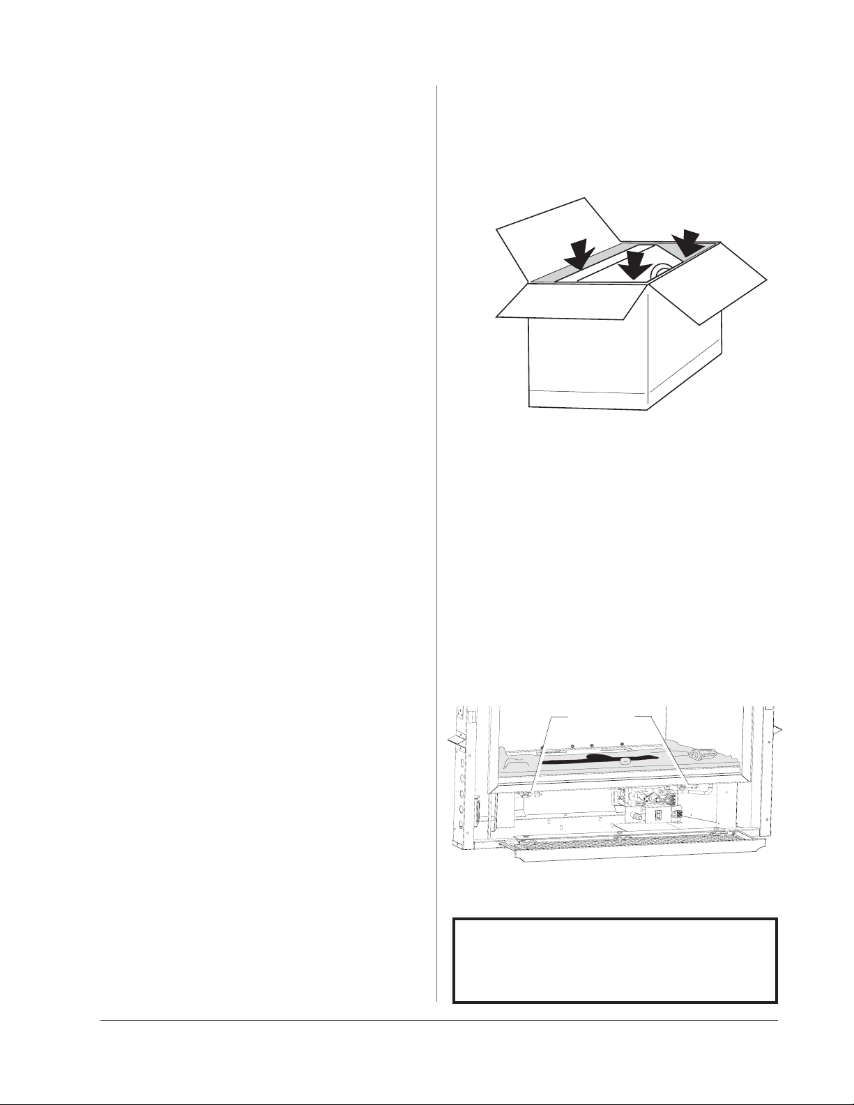
Table of Contents
Specifications ................................... 2
Installation / Service Tools ............ 2
General Information....................... 3
Safety Information .......................... 4
Installation Requirements
Framing ............................................ 4
Mantel Clearances ........................ 6
Hearth Protection ......................... 6
Vent Requirements ....................... 7
Vertical Termination ..................... 8
Horizontal Termination................ 8
Terminal Clearances...................... 9
Vent Restrictor ............................. 10
Fireplace Assembly
Blower Installation...................... 10
Gas Connection ............................ 12
Gas Pressure..................................12
High Altitude Adjustment ........ 13
Fuel Conversion............................ 14
Wall Thermostat ..........................16
Remote Control ............................16
Antique Brick Kit .......................... 17
Log Set Installation ..................... 18
Surround Assembly..................... 19
Unpacking the Fireplace
1. Before you remove the carton, remove the cast
iron parts that are packed around the fireplace
cabinet.
2. Lift the shipping carton off of the fireplace
cabinet.
3. Unpack the Firebox. The Logset is packaged inside
the firebox. Remove the Glass Panel Frame to
unpack the firebox:
• Locate the right and left spring latches on the
underside of the firebox floor. Release each latch
by pulling them forward to disengage the frame
body.
• Pull the Glass Frame away from the firebox and
lift to disengage it from the three steel tabs
located at the top of the firebox. Set the glass out
of the way.
Do not unpack the logs until you are ready to
install them.
Spring Latch
Double Door Installation ........... 19
System Check................................20
Operation.........................................22
Maintenance................................... 23
Glass Replacement........................ 23
Illustrated Parts Breakdown ....... 24
Replacement Parts List.................25
Service Log ....................................... 26
Lighting Instructions .... Back Cover
Pull each Spring Latch to disengage them from the
Glass Frame.
PLEASE READ THESE INSTRUCTIONS IN
THEIR ENTIRETY AND MAKE THEM
AVAILABLE TO ANYONE USING OR
SERVICING THIS APPLIANCE.
3
Page 4
Jøtul GZ 550 Acadia
Direct Vent Gas Fireplace
Manufactured and Distributed by:
Jøtul A.S.A.
Fredrikstad, Norway
Jøtul North America
Portland, Maine
Test Standards
This appliance complies with
National Safety standards
and is tested and listed by Intertek Testing Services of
Middleton, Wisconsin to
ANSI Z21.88-2002•CSA 2.33M02 and CAN/CGA 2.17-M91, CSA P.4.-01.2 for Canada.
DO NOT ATTEMPT TO ALTER OR MODIFY THE CONSTRUCTION OF THE APPLIANCE OR ITS COMPONENTS.
ANY MODIFICATION OR ALTERATION WILL VOID THE
WARRANTY, CERTIFICATION AND LISTING OF THIS
APPLIANCE.
GZ 550 DV Options
• Antique Brick Kit ............................................ 154961
• Two Speed Blower, 125 / 60 c.f.m............. 154967
• 4” x 6-5/8” Adaptor Kit ................................ 154974
• High Altitude Conversion Kit - NG ........... 154977
• High Altitude Conversion Kit - LP ............. 154978
• Fuel Conversion Kit - LP................................ 154937
• Fuel Conversion Kit - NG.............................. 154979
• Wall Thermostat ............................................ 750003
• Remote Control .............................................. 129706
• QuickFace Fronts w/ Screen
Steel Rectangular, Matte Black.................. 154964
Steel Arch, Matte Black................................ 154965
Brushed Stainless Steel, Rectangular ...... 154968
Brushed Stainless Steel Arch...................... 154969
• Arched Double Doors, Matte Black .......... 350560
• Arched Double Doors, Blue Black.............. 350561
• Double Door Basket Screen ........................ 154973
Specifications
Input Rates
Natural Gas
28,000 BTU/hr. maximum input
18,000 BTU/hr. minimum input
Propane
28,000 BTU/hr. maximum input
21,000 BTU/hr. minimum input
Inlet Pressure: MIN MAX
Natural Gas: 5.0 WC (1.24 kPa) 7.0 WC (1.74 kPa)
Propane: 11.0 WC (2.73 kPa) 13.0 WC (3.23 kPa)
Manifold Pressure: MIN MAX
Natural Gas: 1.6 WC (.39 kPa) 3.5 WC (.87 kPa)
Propane: 6.4 WC (1.59 kPa) 10.0 WC (2.48 kPa)
THIS FIREPLACE IS SHIPPED AS A
NN
AA
TURAL GAS TURAL GAS
N
A
TURAL GAS FIREPLACE ONLY. IF
NN
AA
TURAL GAS TURAL GAS
USE WITH PROPANE IS DESIRED,
THE FIREPLACE MUST BE CONVERTED TO USE WITH PROPANE.
FOR YOUR CONVENIENCE THIS
FIREPLACE IS SHIPPED WITH A
PROPANE CONVERSION KIT.
www.nficertified.org
We at Jøtul North America are dedicated to
manufacturing the finest quality hearth
products you can be assured will give you
many years of safe, dependable service.
To ensure your confidence, we recommend
that whenever possible, our products be
installed and serviced by professionals who
are certified by the National Fireplace
Institute (NFI) or, in Canada, by Wood Energy
Technical Training (WETT).
4
Page 5
General Information
IMPORTANT:
SAVE THESE INSTRUCTIONS.
THIS HEATER MUST BE INSTALLED AND
MAINTAINED BY A QUALIFIED SERVICE
AGENCY.
DO NOT ATTEMPT TO ALTER OR
MODIFY THE CONSTRUCTION OF THIS
APPLIANCE OR ITS COMPONENTS. ANY
MODIFICATION OR ALTERATION WILL
VOID THE WARRANTY, CERTIFICATION
AND LISTING OF THIS APPLIANCE.
1. The installation and repair of this appliance must
be done by a qualified service person. Failure to
properly install and maintain this heater could
result in an unsafe or hazardous installation,
which may result in a fire, explosion, property
damage, personal injury or loss of life.
2. This appliance should be inspected before use
and at least annually. More frequent cleaning
may be required due to excessive lint from
carpeting, bedding material, etc. It is imperative
that control compartments, burners and circulating air passageways of the appliance be kept
clean.
`S’assurer que le bruleur et le compartiment des
commandes sont propres. Voir les instructions
d’installation et d’utilisation qui accompagnent
l’appareil.
3. The installation must conform to local codes. Your
local Jøtul authorized dealer can assist you in
determining what is required in your area for a
safe and legal installation. Some areas require a
permit to install a gas burning appliance. Always
consult your local building inspector or authority
having jurisdiction to determine what regulations
apply in your area.
In the absence of local codes, the installation
requirements must comply with the current
National codes. In the U.S., these requirements
are established in the National Fuel Code, ANSI
Z223.1.(NFPA 54). In Canada, the codes have been
established in CAN/CGA B149 Fuel Installation
Code.
Installer l’appareil selon les codes ou reglements
locaux, ou, en l’absence de tels reglements, selon
les Codes d’installation CAN/CGA-B149.
4. DO NOT OPERATE THIS FIREPLACE IF ANY PART HAS
BEEN UNDER WATER.
Immediately call a qualified service technician to
inspect the heater and to replace any part of the
control system and any gas control which has
been under water.
Ne pas se servir de cet appareil s’il a ete’ plonge
dans l’eau, completement ou en partie. Appeler
un technicien qualifie pour inspecter l’appareil et
remplacer toute partie du syste’me de controle et
toute commande qui ont ete plonges dans l’eau.
5. Do not operate the fireplace with the glass front
removed, cracked or broken. Replacement of the
glass should be done by a licensed or qualified
service person. Only remove glass for routine
service. Always handle glass carefully.
Pour utilisation avec les portes en verre cerifiers
aved l’appareil seulemend ou. Ne pas utiliser avec
des portes on verre.
6. Notify your insurance company before proceding
with installation of this fireplace.
Suggested Tools for
Installation and Service
• External regulator (for Propane only)
• Piping which complies with local code
• Manual shutoff valve - T-Handle in MA
• Sediment trap - if required by code
• Tee joint
• Pipe wrench
• Pipe sealant
• 10mm open end wrench
• 1/2”, 7/16” open end wrench
• Phillips head screwdriver
• Flat head screwdriver
• 1/4” nut driver
• Gloves
• Safety glasses
• Torx T20 screwdriver
• Leak test solution
• Reciprocating Saw
• Power Drill
5
Page 6

Safety Information
Installation
Due to the high operating temperatures this
appliance should be located out of traffic and
away from furniture, draperies, etc. Maintain
proper clearance to combustible mantels and
fireplace trim.
Children and adults should be alerted to the
hazards of high surface temperatures and should
stay away to avoid burns or clothing ignition.
Young children should be supervised while they
are in the same room as the Acadia gas fireplace.
Surveiller les enfants. Garder les vetements, les
meubles, l’essence ou autres liquides a vapeur
inflammables loin de l’appareil.
Clothing or other flammable materials should not
be placed ON or NEAR the Acadia gas fireplace.
Never allow any to use the fireplace if they are
unfamiliar with its operation.
NEVER store or use gasoline or any other flam-
mable vapors or liquids in the vicinity of the
Acadia gas fireplace.
Never burn any solid materials (wood, cardboard,
paper, coal, etc.) in this gas fireplace. Use with
natural gas or propane fuel ONLY.
Any safety screen, glass or guard removed for
servicing the appliance must be replaced prior to
operating the appliance.
Do not slam or strike the glass panel.
Were gloves and safety glases while performing
maintenance procedures.
Requirements
The GZ 550 DV Acadia Gas Fireplace and its vent
system must be installed within a totally enclosed
structure. The fireplace must be connected to the
specified vent and termination cap outside the
building. Do not vent into another room or inside
any part of a building.
The approved vent configurations described
herein are derived from extensive testing under
controlled laboratory conditions. Gas appliance
performance can be negatively affected by variables
present in the installation environment, i.e: strong
prevailing winds, steep roofs, nearby trees, snow
accumulation, etc. These conditions should be taken
into consideration by the installer and home owner.
In such instances, system performance can often
be improved by an increase in the vent height or
installation of a high wind termination cap.
Placement and Framing
The combustible framing members of the fireplace
enclosure may be placed in direct contact with the
fireplace cabinet as specified in the illustrations on
the following pages. Use the standoffs integrated
into the sides and top of the front opening to locate
a combustible header and side framing members as
shown in the illustrations. See Fig. 1.
Electrical Power: If the optional Blower (#154967)
will be used, be sure to include provision for a
properly grounded, 120 volt house current outlet at
the fireplace structure.
Electrical Hazard
Be aware of electrical wiring locations when
cutting holes in walls and ceilings for termination.
The optional Acadia Blower (154960) must be
electrically grounded in accordance with local
codes or, in the absence of local codes, with the
current ANSI/NFPA 70, National Electrical Code or
CSA C22.1-Canadian Electrical Code.
The Acadia Blower is supplied with a three-prong
(grounding) plug for protection against shock
hazard and should be plugged directly into a
properly grounded three-prong receptacle. DO
NOT CUT OR REMOVE THE GROUNDING PRONG
FROM THE PLUG.
Always disconect the power supply when per-
forming routine service on the fireplace.
6
Parallel Installation
Although it is possible to place combustible framing
members in direct contact with the rear surface of
the cabinet, the fireplace must be located forward
of the back wall with adequate clearance to accommodate the vent adaptor and subsequent lengths
of vent pipe. Consideration must also be given to
maintaining a minimum 1 inch (25 mm) clearance
between a vertical vent pipe and any combustible
materials to the rear of the unit. See Figs. 2, 3, and 4.
Corner Installation
A corner installation will require that the Vent
Adaptor be installed in a top exit position. Horizontal
terminations will then require use of a 90° elbow.
Figs. 5 and 5a show rear termination with 5/8
Simpson Dura-Vent Wall Thimble #1247.
Page 7
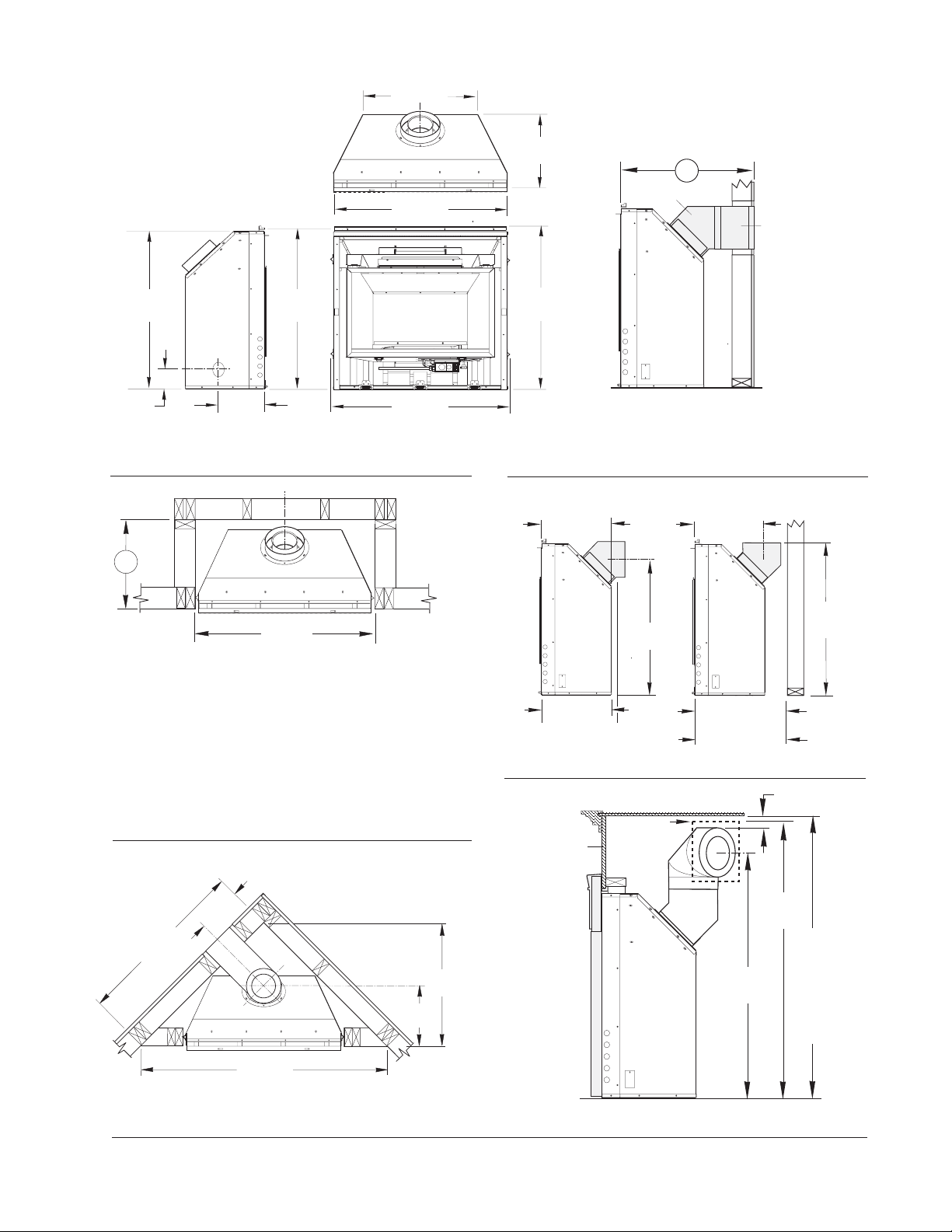
Figure 1. Cabinet Dimensions.
Header Standoff
Height: 36 1/2”
35
890 mm
35 3/4 *
910 mm
25
635 mm
35 3/4
900 mm
16 1/4
410 mm
36 1/2
921 mm
Figure 2. Minimum horizontal vent
allowance through wall.
A
5/8 Vent Adaptor
6 Vent
Section
Wall Cutout :
4/6 Pipe - 10”x10”
5/8 Pipe - 11”x11”
Observe all vent
and termination
clearance
requirements.
4
100 mm
8
200 mm
970 mm
NOTE: DO NOT INSTALL CABINET ON FLOOR SURFACE
LOWER THAN THE FRONTAL HEARTH SURFACE.
A
38
(970 mm)
Horizontal Vent: Minimum depth accomodates the length of
Vent Adaptor and one 6 vent section through wall construction.
Vent Adaptor: 5/8
Vertical Vent: Minimum depth includes 1 inch clearance
between Vent Adaptor and combustible wall construction.
Vent Adaptor: 5/8 4/6
A = 21 3/4
A = 21 1/2 20
Figure 3. Depth requirement to rear wall.
38
Security Vent:
A = 25 1/4 (645 mm)
Security Termination has no slip adjustibility.
Simpson DuraVent and Amerivent:
25 3/4 (660 mm)
A =
Rear Exit
16 1/4
(415 mm)
16 1/4
(413 mm)
19 1/4
(490 mm)
32 3/4
(830 mm)
Top Exit
16 1/4
(415 mm)
5/8 Vent
4/6 Vent
Figure 4. Vent Adaptor orientation.
WALL OPENING
CUSTOM
MANTEL
CABINET
5/8 VENT
11 x 11
280 mm x 280 mm
See text for
details.
21 1/2
(546 mm)
20
(510 mm)
2
50 mm
Min. Vent
Clearance
38 3/4
(990 mm)
9
230 mm
41
1041 mm
56 1/2
1435 mm
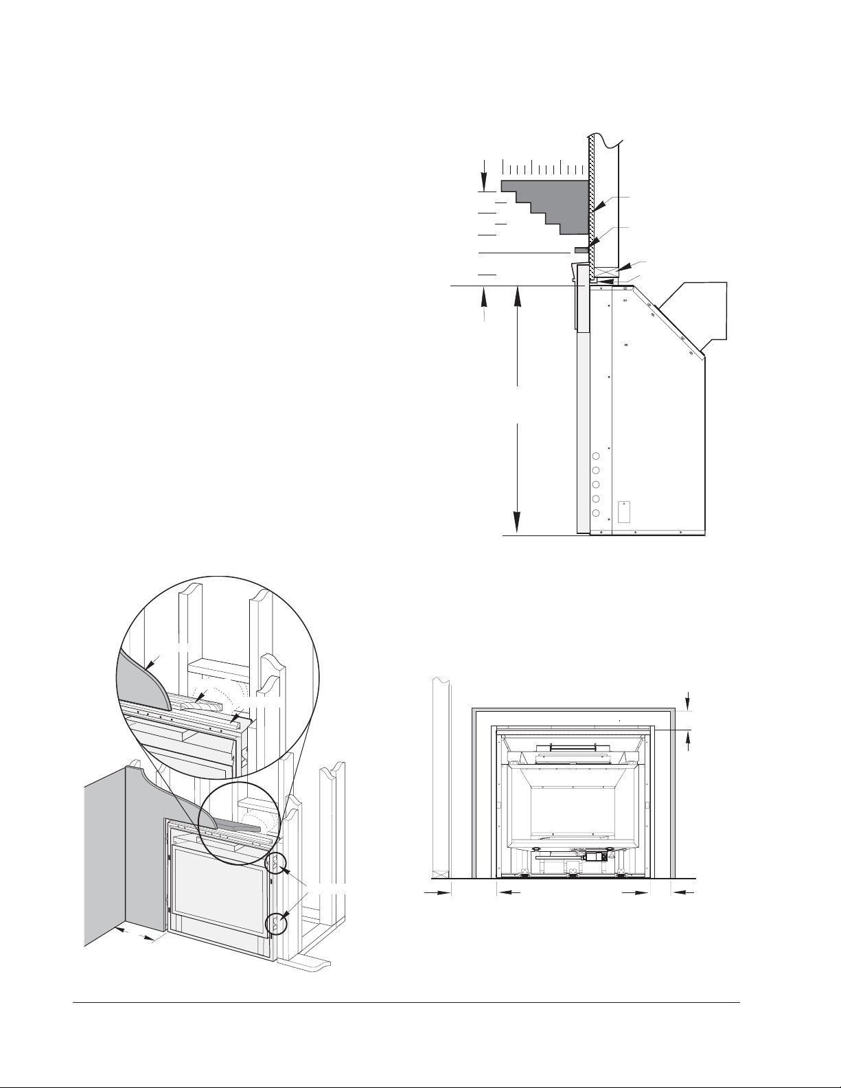
Figure 5. Corner framing dimensions.
16
410 mm
28 1/2
730 mm
48 1/2
1232 mm
49 1/4
1232 mm
Minimum
43
1092 mm
mantel
shelf
height to
cover vent
wall
thimble
Figure 5a. Corner Installation - 5/8 vent, rear termination.
7
Page 8
Hearth Protection
The GZ550 Acadia is approved for installation
without hearth protection. Combustible materials
may be used on the floor directly under and in front
of the fireplace. NOTE: The floor surface under the
unit must be level with or higher than the surface
in front of the unit in order for the fireplace
Controls Door to open properly.
Facing and Clearance Requirements
The following clearance and hearth specifications
are the minimum requirements for the GZ550
Acadia gas fireplace. Measure clearances from the
steel fireplace cabinet - not the cast iron surround
panels. See Figures 6 - 8.
A combustible surface is anything that can burn
(i.e. sheet rock, wallpaper, wood, fabrics etc.). These
surfaces are not limited to those that are visible and
also include materials that are behind non-combustibles.
If you are not sure of the combustible nature of
a material, consult your local fire officials. “Fire
Resistant” materials are considered combustible they are difficult to ignite, but will burn. “Firerated” sheet rock is also considered combustible.
Maintain the proper clearances to the appliance
to allow adequate flow of ventilation air around
the fireplace.
Mantel and Trim Clearance
12
13 1/2
12
10 1/2
9
7 1/2
4 1/2
TOP OF CABINET
35
Figure 7. Minimum Mantel Clearances. Measure
clearances from the top of the fireplace cabinet
before installation of the cast iron surround panels.
4 8
MANTEL
AREA
DRYWALL
UPPER TRIM
2 1/2 Max. Depth
HEADER
STANDOFF
CAST IRON SURROUND PANELS
Wallboard
Header
10”
(250 mm)
Figure 6. Header and Side Standoffs
8
Standoff
Standoffs
TOP TRIM
4 1/2
1.2 cm
SIDE TRIM
GZ550 DV
SIDE WALL
10
2.55 cm
Cabinet
4 1/2
1.2 cm
Figure 8. Minimum Side Wall and Trim Clearance.
Measured from the cabinet, not standoffs or cast iron
panels.
Page 9
Vent Requirements
Horizontal Overhang
The GZ550 DV Acadia Gas Fireplace is approved for
use with direct vent components produced by the
following manufacturers:
• Simpson Dura-Vent Corporation, 5/8 and 4/6 pipe
• Security Vent Ltd. International, 5/8 and 4/6 pipe
• Amerivent Corporation, 4/6 pipe
Use vent components from a single vent manufacturer. Do not combine parts from different
manufacturers in a single installation.
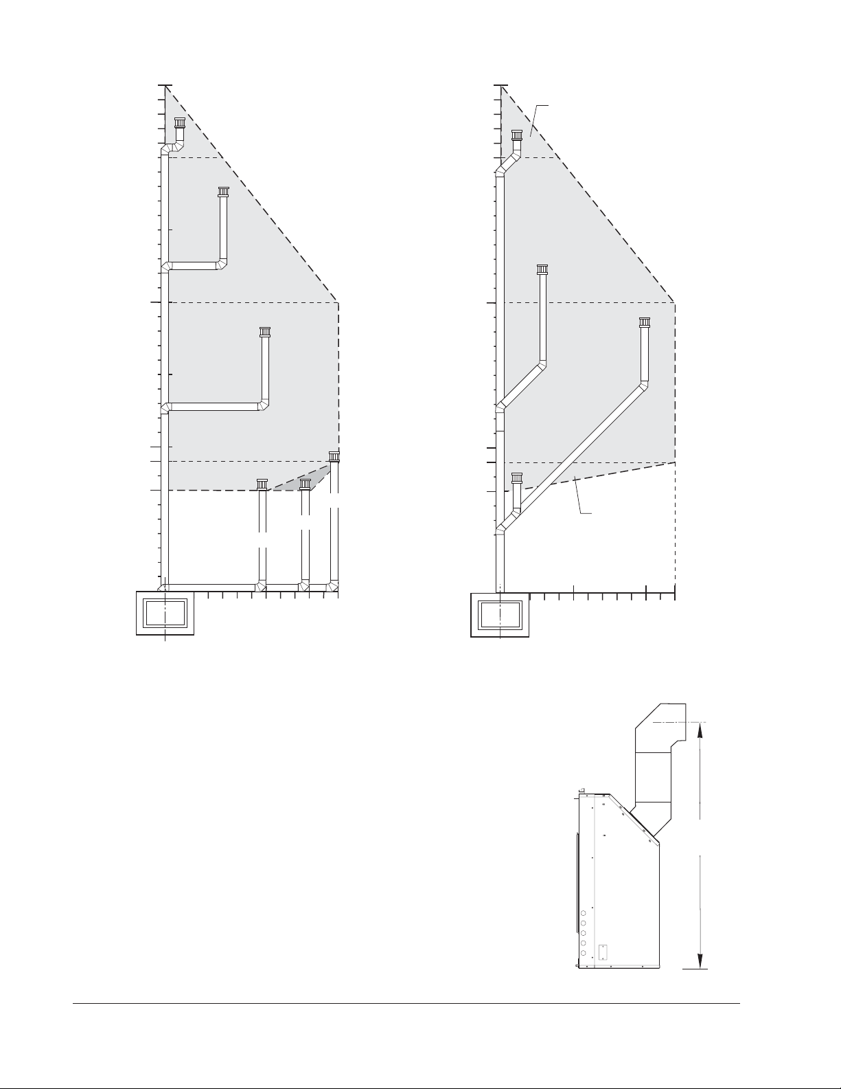
The vent termination must fall within the shaded area
designated in the diagrams in Figures 12 - 14.
Venting Guidelines
The minimum height for a vertical termination
cap must be no less than 7' from the top of the
unit. The maximum height must not exceed 35'.
The minimum vent height above the roof or
adjacent walls is specified by major building
codes. Use the Gas Vent Rule as a general guide.
See Fig.10. requirements of the approval listing
and the manufacturer’s instructions.
Clearance (airspace) between Vent and Combustibles:
Top - 2” (51 mm) Sides/Bottom - 1” (25 mm)
Wall Cutout Dimensions:
4/6 Pipe - 10” x 10” 5/8 Pipe - 11” x 11”
Any horizontal run must rise 1/4” per foot.
Install venting in accordance with the vent
manufacturers’ instructions. Never modify any
venting component, or use any damaged venting
product.
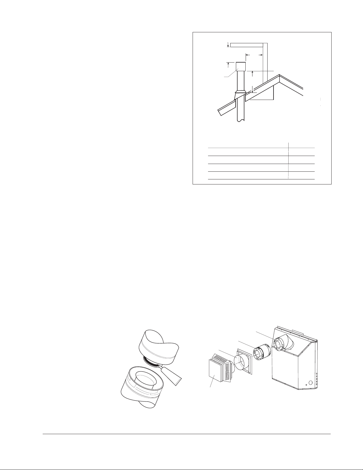
2 ft.
min.
Vertical Wall
Lowest Discharge
Opening
Termination
Cap
2 ft.
min.
H
X
Roof Pitch
12
H = minimum height from roof
to lowest discharge opening
ROOF SLOPE
Flat to 6/12 1’0” 0.3M
Over 7/12 to 9/12 2’0” 0.6M
Over 10/12 to 12/12 4’0” 1.2M
Over 13/12 to 16/12 6’0” 1.8M
Over 17/12 to 21/12 8’0” 2.4M
Figure 10. Gas Vent Height Rule: Vertical vent
termination height above roof.
Do not recess the vent terminal into a wall or siding.
Inspect the vent system annually for blockage and
deterioration.
Installation of any components not manufactured
or approved by Jøtul or failure to meet all clearance requirements will void all warranties and
may result in property damage, bodily injury, or
loss of life.
is X / 12
Minimum
Height from Roof
THE GAS APPLIANCE AND VENT SYSTEM MUST BE
VENTED DIRECTLY TO THE OUTSIDE OF THE BUILDING.
DO NOT CONNECT VENT TO A CHIMNEY SERVING A
SOLID FUEL OR ANOTHER GAS
APPLIANCE.
Joint Sealing Requirement: Apply
a 1/8” bead of high-temperature
(750°F) sealant to the male
section of the inner vent pipe.
See Fig. 9.
The cement should seal the
inner pipe from the outer
pipe.
Figure 9. Seal each inner joint before joining pipe .
IN DESIGNING THE VENT SYSTEM, DO NOT
COUNT THE 45° ELBOW CONNECTED TO THE
VENT COLLAR AS AN ELBOW.
45° Elbow
6” Vent Section
Wall Support
S
E
A
L
A
N
T
Wall Termination
Figure 11. Typical minimum horizontal vent
configuration - 5/8 Simpson DuraVent. Do not use 4/
6 pipe in this configuration.
9
Page 10
35
52
(990 mm)
Restrictor
Fully Closed
35
Restrictor
Fully Closed
30
20
From Vent Collar
Height in Feet
10
9
Minimum
Max.Two
Elbows -
90° or 45°
Height
7
Restrictor
2/3 Closed
Restrictor
1/3 Closed
Restrictor
Open
4/6 Vent
5/8 Vent
Both
30
20
Restrictor
From Vent Collar
Height in Feet
10
1/3 Closed
9
7
Restrictor
2/3 Closed
Restrictor
Open
Max.Two 45°
Elbows
12
10
7
Horizontal Run in Feet
Figure 12. Vent Window for vertical termination using
5/8 or 4/6 pipe.
Vertical Termination
The vent must terminate within the shaded area
designated on the graphs in Figs. 12 and 13.
• Maximum Elbows - Two 90° or Two 45° (Do not
count the first elbow off the vent collar.)
• Use the restrictor settings indicated in the graph
as general guide. The specific characteristics of
your installation may require different settings.
Horizontal Termination
The vent must terminate within the shaded area
designated in Figs. 15 and 16. (Do not count the first
elbow off the vent collar.)
• Max. Elbows - One 90° or one 45°.
• Use of 4/6 pipe requires a minimum 1 foot rise. Fig. 14.
5
Horizontal Run in Feet
Figure 13. Vent Window for offset vertical
termination using 5/8 or 4/6 pipe.
Figure 14. Minimim
centerline for
horizontal
termination of 4/6
pipe
10
12
10
Page 11

12
12
9
5
3
Max. One 90°
Elbow
5
10
12
From Vent Collar
Height in Feet
Horizontal Run in Feet
Figure 15. Horizontal termination -5/8 pipe.
Horizontal Termination Clearance
9
5
From Vent Collar
Height in Feet
1
3
Horizontal Run in Feet
Figure 16. Horizontal Termination - 4/6 Pipe.
Minimum 1 ft. rise required.
Max. One 90°
5
Elbow
10
12
Figure 17. Vent Terminal Clearances - National Fuel Gas Code.
A = Clearance above grade, veranda, porch , deck, or
balcony : *12 inches (30 cm) minimum.
B = Clearance to window or door that may be opened:
Min. 9 inches, U.S. / *12 inches (30 cm) CAN.
We recommend 12in. minimum to prevent condensation on the window.
C = Clearance to permanently closed window:
Min. 9 inches, U.S. / *12 inches (30 cm) CAN
We recommend 12in. minimum to prevent condensation on the window.
D = Vertical clearance to ventilated soffit located above
the terminal within a horizontal distance of 2 feet (60 cm)
from the centerline of the terminal: 18 inches
(46 cm) minimum.
E = Clearance to unventilated soffit: *12 inches (46 cm)
minimum.
F = Clearance to outside corner: Min. 9 inches, U.S. / *12
inches (30 cm) CAN. We strongly recommend 12 inches,
particularly where windy conditions pevail.
* As specified in CGA B149 Installation Codes. Note: Local Codes
and Regulations may require different clearances.
G = Clearance to inside corner: Min. 6 inches, U.S. / *12
inches (30 cm) CAN. We strongly recommend 12 inches,
particularly where windy conditions pevail.
H = *Not to be installed above a meter/regulator assembly
within 3 feet (90 cm) horizontally from the center-line
of the regulator.
I = Clearance to service regulator vent outlet: 6 feet (1.8
m) minimum.
J = Clearance to nonmechanical air supply inlet to building
or the combustion air inlet to any other appliance: *12
inches (30 cm) minimum.
K = Clearance to a mechanical air supply inlet: *6 feet
(1.8 m) minimum.
L = ** Clearance above paved sidewalk or a paved driveway
located on public property: *7 feet (2.1 m) min.
M = Clearance under veranda, porch, deck, or balcony: *12
inches (30 cm) minimum.
** A vent shall not terminate directly above a sidewalk or driveway
which is located between two single family dwellings and serves
both dwellings.*
1
Only permitted if veranda, porch, deck, or balcony, is fully open
on a minimum of two sides beneath the floor.*
1
11
Page 12

Fireplace Installation
12
305
mm
Figure 18. Wall Vent Terminal / Overhang Clearances
2 1/2
64 mm
3
76 mm
Variable Vent Restriction
Vent restriction is accomplished by sliding two
restrictor panels over the combustion air intake ports
located at the back of the firebox, just below the
logset base. See Fig 19. The panel levers will be most
accessible with removal of the logset.
The panels are set in a fully open position at the
factory. Push each lever toward the center of the
firebox to increase restriction in one inch increments,
e.g: 1 inch travel = 1/3 closed position.
Use the Vent Window diagrams in Figs. 12-13 as a
starting point to determine the best restriction
setting. The ideal restrictor setting for a particular
vent system will vary depending on the specific
installation characteristics. Once the fireplace is
operating, further restrictor adjustment may be
necessary to obtain the best performance. See the
Operation chapter of this manual for further information.
Optional Blower
Install the optional Blower (154967) before installing
the gas supply line. The 125 CFM heat-activated fan
unit will be located in the bottom rear of the fireplace cabinet.
Power Requirement
The blower must be electrically grounded in accordance with local codes or, in the absence of local
codes, with the current NFPA 70- National Electrical
Code or CSA C22.1-Canadian Code.
A three-prong (grounding) power supply plug is
included for protection against shock hazard and
should be plugged directly into a properly grounded
three-prong receptacle. DO NOT CUT OR REMOVE
THE GROUNDING PRONG FROM THE PLUG.
Blower Function
The blower is controlled by a heat activated switch
(snapstat) that will ONLY function if the blower
control switch is either in the HI or LOW setting.
Once the unit has been operating for a short time
and the firebox heats, the blower will start on either
the HI or LOW speed.
Conversely, once the unit is off the blower will
continue to operate until the snapstat cools and
turns the blower off.
If the blower is not needed, place the blower
control switch in the OFF position and the snapstat
will not function.
CAUTION: Always unplug the Blower when
performing any routine service to the Acadia gas
fireplace.
FULLY CLOSED
2/3 CLOSED
1/3 CLOSED
FULL OPEN
Figure 19. Vent restrictor settings.
12
FULLY CLOSED
2/3 CLOSED
1/3 CLOSED
FULL OPEN
Installation
1. Insert a rubber grommet at each corner of the
Base Plate as shown in Fig. 20.
2. Engage the Blower unit base with the four studs
at the rear of the fireplace cabinet floor. See Fig. 21.
3. Using the M6 nuts and 10 mm socket, attach the
Control Switch / Snapstat Bracket to the two
studs protruding from the firebox floor. See Fig.
22. Be sure that the snapstat disc firmly contacts
the bracket surface.
4. Run the power cord through the opening in the
side of the cabinet nearest the receptacle. Gather
slack cord into the side cavity, away from the
plumbing and other wiring.
Page 13

1. #129374 Fan/Motor Unit
2. #220012 Base Plate
3. #220050 Control Switch, Snapstat
4. #220055 Rubber
Grommets, 4
5. #9930 M6 Hex
nuts, 2
4
1
2
5
Figure 20. Blower Kit 154967 contents.
Figure 21. Blower location.
Final Cabinet Positioning
1. If appropriate, attach the 4/6 Vent Adaptor
Collar:
• Remove the 5/8 Collar supplied with the unit.
• Align the 4/6 Collar as shown in Fig. 23 and
secure to the unit using the original screws. Be
sure the single round fastener hole is oriented to
the 12 o-clock position for proper vent alignment.
3
I
H
F
F
O
O
L
1. Side Standoffs: Remove the retainer screws. Using
vise grips or pliers, fold each standoff at the
perforations. Secure each standoff using the
screws previously removed. See Fig. 24.
2. Wall Stud Brace: Loosen, bend, and position each
cabinet Retainer Strap for attachment to the
fireplace enclosure. Fig. 24.
3. Locate the fireplace cabinet in its final position
within the enclosure. Confirm that the first 45°
Elbow is correctly aligned for final vent assembly
and secure it to the Vent Collar using 3, #10 sheet
metal screws.
4. Confirm that the cabinet is positioned to align its
forward edge with the finished surface of the
wall facing. The stud braces allow approximately
2 inches of forward adjustment to accommodate
most any facing thickness. Secure the braces to
the enclosure frame.
5. Complete the gas line and electrical power
routing as appropriate for blower and thermostat functions.
10 mm
Nuts
Figure 22. Install Control Switch.
For correct vent pipe
alignment, be sure the
round hole is oriented to
the 12- o’clock position
Figure 23. 4/6 Vent Collar orientation.
Standoff in shipping position.
Remove, bend and
reattach each Standoff.
Remove, bend and
reattach each Wall
Stud Brace.
Figure 24. Standoff and Stud Brace orientation.
13
Page 14

Connect the Gas Supply
Gas Supply Requirements
ALL INSTALLATIONS MUST COMPLY WITH LOCAL
CODE OR IN THE ABSENCE OF LOCAL CODE, MUST
COMPLY WITH THE MOST RECENT EDITION OF THE
NATIONAL FUEL GAS CODE ANSI Z223.1/NFPA 54 OR
CAN-B149.
Shutoff Valve
All codes require a gas shutoff valve (gas cock)
and union to be installed in the supply line and in
the same room as the appliance. This allows for the
disconnection of the fireplace for servicing and
maintenance. See Fig. 25.
A T-handle gas shutoff valve is required in
Massachusetts in compliance with Code 248CMR.
The fireplace and gas control valve must be
disconnected from the gas supply piping during any
pressure testing of the system at test pressures in
excess of 1/2 psig. For pressures lower than 1/2 psig,
isolate the gas supply by closing the manual shutoff
valve.
Leak test:
• Mix a 50-50 solution of water and dish soap.
• Light appliance- see lighting instructions on page
23 of this manual or on the fireplace’s rating
plate.
• Brush or spray all joints and connections with the
soapy water solution.
• If bubbles appear at any connection or seam or a
gas odor is detected, immediately turn gas
control knob to the OFF position.
Tighten or reconnect the leaking joint and retest
for any gas leaks.
Control Valve Connection
The gas supply line connection is made to the
left side of the valve. The gas supply line should be a
minimum 3/8" diameter, or the appropriate size to
provide sufficient gas pressure to the valve regardless of the input setting.
The use of flexible gas appliance connectors is
acceptable in many areas in the U.S. In Canada,
methods vary depending on local code. If local codes
permit, use flexible gas line for ease of installation
and service. For those locales where flexible gas
lines are not permitted, use the 3/8” iron fitting to
make the connection at the left side of the Control
Valve. See Figures 25 and 26.
Secure all joints tightly using appropriate tools
and sealing compounds (for propane units, be sure
to use compounds that are propane resistant). Turn
on gas supply and test for gas leaks using a soapy
water solution. Never use an open flame to check
for leaks.
Figure 25. Gas supply line fittings.
Gas Pressure
Proper gas pressure provides a consistent flow
of gas to the appliance and is instrumental in
checking for gas leaks. The gas control valve on the
fireplace is equipped with pressure test points for
gauge connections. The gauge connections are
located on the front of the valve under the On/Off/
Pilot knob. Gauge connections are identified by:
• IN/E for inlet or supply pressure (the amount of
gas coming to the valve.)
•OUT/A for manifold pressure (the amount of gas
that is coming out of the valve to the burner.)
14
EA
Figure 26. Pressure test point as located on the
front of the valve.
Page 15

The appliance must be isolated from the gas
supply line by closing its individual manual gas
shutoff valve (gas cock) during any pressure testing
of the gas supply piping system that is equal to or
exceeds pressures of 1/2 psig (3.5 kPa).
Inlet Pressure
Natural Gas: 5.0 WC (1.24 kPa) 7.0 WC (1.74
kPa)
Propane: 11.0 WC (2.73 kPa) 13.0 WC (3.23
kPa)
MIN MAX
Natural Gas: 1.6 WC (.39 kPa) 3.5 WC (.87 kPa)
Propane: 6.4 WC (1.59 kPa) 10.0 WC (2.48 kPa)
ALWAYS TEST PRESSURE WITH VALVE CONTROL KNOB
SET ON HIGH. Symptoms of incorrect gas pressure
include:
Insufficient gas pressure:
• Small pilot flame which can result in insufficient
millivolts.
• Little variation in flame picture between HI and
LO settings.
• Insufficient gas to support more than one appli-
ance causing nuisance outages or gas surges.
Excessive gas pressure:
• Permanent damage to valve causing complete
appliance shut down.
• Too large a pilot flame resulting in overheating of
the power generator and consequent shut down.
• Sooting due to impingement and/or incorrect fuel
to air mix.
MIN MAX
Manifold Pressure
High Altitude Adjustment
Installations located at altitudes from 2000 - 4500 ft.
(610 M - 1370 M), require compensation for the
thinner air (less volume of air per cubic foot). Higher
altitudes affect the atmospheric pressure and heat
value of gaseous fuels. The lower oxygen content in
the air and the lower gas viscosity require the use of
a different orifice to achieve efficient, clean combustion at the burner tube.
For high altitude installations consult the local
gas distributor or the authority having jurisdiction
for proper rating methods. If the installer must
convert the unit to adjust for varying altitudes, use
Jøtul High Altitude Kit (#137403).
In the U.S: THE DERATING KIT MUST BE INSTALLED BY
AN AUTHORIZED SERVICE TECHNICIAN IN ACCORDANCE WITH THE MANUFACTURER’S INSTRUCTIONS
AND ALL CODES AND REQUIREMENTS OF THE
AUTHORITY HAVING JURISDICTION. THE INFORMATION STICKER MUST BE COMPLETED BY THE INSTALLER AND APPLIED TO THE APPLIANCE AT THE
TIME OF THE CONVERSION. THE QUALIFIED SERVICE
AGENCY PERFORMING THIS WORK ASSUMES RESPONSIBILITY FOR THIS DERATING.
In Canada: This unit has been tested for installation
at high altitudes in accordance with Canadian test
standard CAN/CGA-2.17. THE DERATING SHALL BE
CARRIED OUT IN ACCORDANCE WITH THE REQUIREMENTS OF THE PROVINCIAL AUTHORITIES HAVING
JURISDICTION AND IN ACCORDANCE WITH THE
REQUIREMENTS OF THE CAN1-B-149.1 AND .2
INSTALLATION CODE.
Derating Procedure
1. Follow Steps 1-4 of the Fuel Conversion procedure
outlined on page 14.
2. Remove the original orifice. Consult Table 1 to
determine the correct orifice size for your elevation and fuel type. Install the appropriate orifice
included in the high altitude kit.
3. Fill out the high altitude conversion label and
attach to the rating plate or fireplace cabinet floor
See Figure 27.
4. Reassemble the firebox components.
5. It may be necessary to adjust the air shutter on
the burner tube. See the AIR SHUTTER/FLAME
APPEARANCE section of this manual for more
details.
High Altitude Orifice Chart
Elevation Fuel
0 - 2000 ft. Natural Gas #37 220018
(0 - 610 m) Propane 1.55 mm 220048
2001 - 4500 ft. Natural Gas #38 129130
(611 - 1370 m) Propane 1.50 mm 129146
Table 1. High Altitude Orifice Chart.
THIS STOVE HAS BEEN CONVERTED FOR USE AT AN
ALTITUDE OF: ________________
Orifice Size: ____________ Manifold Press. _____
Input Btu/Hr. ___________ Fuel Type __________
Date of Conversion ___________
Figure 27. High Altitude Conversion Label.
Orifice
Size
Part No.
15
Page 16

Fuel Conversion
The GZ550 DV Acadia Fireplace is designed to for use
with either Natural gas or Propane. It is shipped
from the factory configured to use Natural gas. A
conversion kit is included for conversion to Propane
use if desired. Check the identification label on the
Control Valve to confirm that the correct fuel is used.
WARNING:
THE CONVERSION KIT IS TO BE IN-
STALLED BY AN AUTHORIZED JØTUL
SERVICE TECHNICIAN IN ACCORDANCE
WITH THE MANUFACTURER’S INSTRUCTION AND ALL CODES AND REQUIREMENTS OF THE AUTHORITY HAVING JURISDICTION. FAILURE TO FOLLOW THESE
INSTRUCTIONS COULD RESULT IN SERIOUS INJURY OR PROPERTY DAMAGE. THE
QUALIFIED AGENCY PERFORMING THIS
WORK ASSUMES RESPONSIBILITY FOR
THIS CONVERSION.
IN CANADA:
THE CONVERSION SHALL BE CARRIED
OUT IN ACCORDANCE WITH THE REQUIREMENTS OF THE PROVINCIAL AUTHORITIES
HAVING JURISDICTION AND IN ACCORDANCE WITH THE REQUIREMENTS OF THE
CAN1-B149.1 AND .2 INSTALLATION CODE.
Cet equipement de conversion sera installe par une
agence qualifiee de service conformement aux
instructions du fabricant et toutes exigences et
codes applicables de l’autorises avoir la juridiction.
Si l’information dans cette Instruction n’est pas
suivie exactement, un fey, explosion ou production
de protoxyde de carbone peut resulter blessure
personnelle de vie. L’agence qualifiee de service est
esponsable de l’installation n’est pas propre et
complete jusqu’a l’operation de l’appareil converti
est cheque suivant les criteres etablis dans les
instructions de proprietaire provisionnees avec
l’equipement.
Tools required:
1/4” Nut driver, 7/16” and 1/2” open end wrench or
deep well socket, 4 mm allen wrench, Torx t20 or
slotted screwdriver.
Conversion Kit Contents:
• 1 Regulator Tower labeled for Propane
• 3 Regulator Tower Screws
• 1 Burner Orifice (#37 NG, 1.55 mm LP)
• 1 Pilot Orifice ( #30 for LP, #51 for NG)
• Label A - to be completed and applied to the
back of the fireplace.
• Label B - apply to the fireplace Rating Plate as
designated on the plate.
WARNING: If appropriate, be sure to unplug the
blower before proceeding with this conversion.
Fuel Conversion Procedure
1. Remove the Glass Frame:
• Follow the removal procedure detailed on page
1.
2. Empty the firebox:
• Lift and remove the Fettle and Logset package.
CAUTION: THE LOGS ARE FRAGILE. Handle them
with care and set aside out of the way.
• Remove the Logset Base by lifting it out of the firebox.
3. Change the Burner Orifice:
• Loosen the locknut on the Air Shutter Stem, located
under the firebox floor to the right of the Control
Valve. This will allow you to disengage the Burner
Tube. Fig. 28.
• Remove the Orifice Cover Plate. Fig. 29.
• Lift the rear of the Burner Tube and rotate
slightly forward. Slide the tube to the left
enough to disengage it from the Air Shutter and
Burner Orifice, then lift out. Slide the Air Shutter
back out of the way to expose the orifice. Fig. 29.
• Using a ½” open end wrench or deep well socket
remove the burner orifice and replace with the
appropriate orifice, supplied in the kit.
4. Change the Pilot Orifice:
• FROM WITHIN THE FIREBOX, disengage the
Pilot Hood by releasing the retainer clip as
shown in Fig. 30. Using a 4 mm allen wrench,
unscrew the pilot orifice (counter clockwise).
Replace with the appropriate orifice:
#51 for Natural gas
#30 for Propane
Tighten new orifice into the base of the pilot
assembly.
16
Page 17

Pull Frame Spring
Latch to release.
Air Shutter
Wingnut
Figure 28. Frame latch and air shutter stem
location.
Burner Tube
Pilot Assembly
Air Shutter
Cover Plate
Figure 29. Remove the Orifice Cover Plate and
Burner Tube.
Pilot Hood
Pilot Orifice
Retainer Clip
PILOT ASSEMBLY
• Replace Pilot Hood by pushing it into the base.
5. Replace the Burner Tube:. Slip the end of the tube
into the Air Shutter and SLIDE TUBE TO THE RIGHT
TO COMPLETELY COVER THE ORIFICE.
6. Adjust the Air Shutter: See Fig. 31.
• Slide the shutter to the left to open the inlet,
slide to the right to close. The standard settings
are: Natural gas - 1/4” open
Propane - 1/2” open
• Replace the Cover Plate.
7. Change the Regulator: See Fig. 32.
• Using a Torx T-20 screwdriver or small flat head
screwdriver, remove the three specialty screws
from the front of the valve regulator.
• Remove the regulator tower and gasket.
BE SURE TO REMOVE THE BLACK RUBBER GASKET
FROM THE VALVE.
• Install the new variable regulator tower with
the new rubber gasket. Thoroughly tighten new
regulator to valve body.
8. Apply the Conversion Labels:
• Apply LABEL A to the cabinet floor so that it
may be seen by anyone servicing the fireplace.
• Apply LABEL B to the Rating Plate in the space
provided.
9. Reassemble the fireplace, apply gas to the system
and check for gas leaks including all gas lines
before and after the valve. NEVER USE AN OPEN
FLAME TO CHECK FOR GAS LEAKS.
IMPORTANT: Correct gas pressure is essential for
efficient and safe operation. It is important that
the correct gas pressure be established at the
time of the installation. For more details, see the
Gas Pressure section of this manual on page 12.
WHEN LIGHTING THIS APPLIANCE, ALWAYS REFER TO
THE LIGHTING INSTRUCTIONS ON THE BACK COVER
OF THIS MANUAL.
Figure 30. Pilot Orifice replacement.
Air Shutter
Injector
Burner
Orifice
Stem
Figure 31. Burner orifice removal and replacement.
BE SURE TO
REMOVE THE
BLACK
RUBBER
GASKET
FROM THE
VALVE.
Figure 32.
Valve Regulator replacement.
17
Page 18

Wall Thermostat Installation
Use Jøtul Thermostat #129706 or a 750 millivolt DC
two-wire circuit thermostat to automatically control
your fireplace operation. The thermostat should be
placed in the same room as the heater, typically 5’
off the floor. Avoid drafty areas or any area that
may affect the accuracy of the thermostat.
The thermostat should be connected to the
Acadia using a minimum of 16 gauge wire with a
maximum length of 35 feet of wire.
Connect the two thermostat wire leads to the
two lower terminals on the terminal block located
to the right of the ON/OFF/T’STAT switch. Do not
overtighten the connections. IT IS NOT NECESSARY
TO DISCONNECT ANY OTHER WIRES. See Figure 34.
At the thermostat, the two wires should be
connected to the two connections screw on the
thermostat base plate per the manufacturer’s
instructions.
For thermostatic function, place the ON/OFF/TSTAT switch in the T-STAT position and the pilot
flame must be lit.
ROCKER
SWITCH
OPTIONAL
THERMOSTAT
REMOTE
CONTROL
ON
OFF
STAT
or
TH
TP
TH
TP
VALV E
THERMOPILE
TERMINAL
BLOCK
Figure 34. ZG550 Acadia Wiring Diagram
Remote Control
The optional Jøtul Remote Control can be installed
on the Acadia gas fireplace. Using the wire supplied with the remote, connect the remote directly
to the gas control valve.
Connect one receiver lead to the terminal
labelled TH. Connect the other receiver lead to the
terminal labeled TH/TP. DO NOT DISCONNECT ANY
OTHER WIRES FROM THE VALVE, AND DO NOT OVER
TIGHTEN THE TERMINAL SCREWS.
Place the receiver unit under the control valve
on the floor of the fireplace cabinet.
BLOWER
GREEN
WHITE
POWER
SUPPLY
BLACK
BLACK
WHITE
BLACK
LO HI
RED
SNAPSTAT
RED
CONTROL
SWITCH
Figure 33. ZG550 DV Acadia Blower Wiring Diagram
CAUTION:
LABEL ALL WIRES PRIOR TO DISCONNECTION WHEN SERVICING
THE CONTROLS. WIRING ERRORS
CAN CAUSE IMPROPER AND DANGEROUS OPERATION. ALWAYS
VERIFY PROPER OPERATION AFTER
SERVICING THE APPLIANCE.
ATTENTION:
AU MOMENT DE L’ENTRETIENDES
COMMANDES, ETIQUETEZ TOUS LES
FILS AVANT LE DEBRANCHEMENT.
DES ERREURS DE CABLAGE
PEUVENT ENTRAIUN
FONCTIONNEMENT INADEQUAT ET
DAGEREUX.
18
Page 19

Brick Panel Assembly
Install the optional Brick Panels before placing the
Logset. Place the panels in position in the order as
numbered in Fig. 32. No fasteners or tools are
required.
Upper Rear Panel,
220031
4
Left Side
Panel,
220032
1
3
2
Lower Rear Panel,
220030
Right Side
Panel,
220033
Figure 35. Panel installation order.
1. Remove the Glass Frame, if you have not already
done so. Open the lower control panel and locate
the two frame latches under the firebox floor. See
Fig. 36. Pull the latch handle forward to disengage
it from the bottom of the glass frame. You can
then pull the frame out and up off of the three
retainer tabs at the top of the firebox opening.
Set the Glass Frame out of the way.
2. Remove the Fettle and Logset. These parts are not
fastened. Simply lift them out of the firebox.
3. Install the Side Panels. Engage the bottom edge
of each side panel between the Logset Base and
the firebox wall and push the panel forward
against the front lip of the firebox opening. See
Fig. 37.
4. Install the Lower Rear Panel. Orient the panel so
that the beveled edge is on top and the mortar
joints align with those on the side panels. Engage
the bottom edge between the rear wall and the
base. Press the panel snugly between the two
side panels. See Fig.38.
5. Install the Upper Rear Panel. This will also be a
snug fit. Set the panel up high and then carefully
lower it to seat its lower edge against the top of
the other rear panel. The side panels will hold it in
place.
Pull Frame Latches to
Release Frame
Figure 36. Glass Frame latch locations.
Side
Panel
Logset Base
Figure 37. Install the Side Panels.
Bevelled Edge
Figure 38. Install Lower Rear Panel.
19
Page 20

Logset Assembly
Unpack and arrange the logs as outlined below.
CAUTION: The logs are fragile. Handle with care.
1. Set the Log Base in position in the bottom of the
firebox, pushing it all the way to the rear.
2. Seat Left Log A in the shallow pocket at the left
side of the Base. Fig. 39.
3. Engage Forked Log B with the pin on Log A and
position as shown in Fig. 40.
4. Position the short, flat side of Log End C within
the shallow pocket at the right side of the Base.
See Fig. 41.
5. Engage Log Tip D with the pin in Log B and
position it against Log C. Fig. 42 shows the
correct placement. There should not be a large
gap between the two pieces as shown in Fig.42a.
6. Position Log E to the rear of Log C. Note that the
cutout at in the lower end should be oriented to
the left to clear the Restrictor lever as shown in
Fig. 43.
7. Replace the Glass Panel Frame: Engage the top
of the frame with the three tabs at the top of
the firebox. Push the bottom of the frame
against the firebox face and pull the Frame
Latches out to engage them with the slots in the
bottom of the frame.
Log End C
Figure 41. Position Log C to the right.
Log Tip D
Figure 42. Correct Position: Engage Log D to Logs B and C.
Log Base
Figure 39. Position Log A in the pocket at left.
Log B
Figure 40. Engage Log B with Log A.
Figure 42a. Incorrect Log Position.
Log E
Figure 43. Engage notched Log E.
20
Page 21

Surround Assembly
1. Install the Lower Grill / Control Door.
• Secure the hinges to the cabinet frame using
the hex head screws provided in the hardware
bag. Fig. 44.
2. Install each of the Side castings onto the
cabinet by engaging the hanger tabs with the
holes in the cabinet frame. See Fig. 52 for
orientation.
3. Install the Right and Left Upper Grill plates.
4. Attach the Inner Panel to the Center Plate. The Inner
Panel may be reversed to show the winter scene.
(Note: Blue Black Panel is enamelled on one side only).
5. Hang the Center Plate in position.
Optional Double Door
The Double Door set is fully assembled and requires
no tools for installation. Use the 4 mm hex key
supplied with the doors to adjust the door alignment
at the eight socket head hinge screws.
Door Installation
Unpack the door set and inspect the parts for
damage. Notify your dealer if any damage is found.
You may wish to remove the doors from the
frame to lighten the assembly and ease installation.
They simply lift off of the hinges.
The door assembly attaches to the fireplace by
engaging the three slots in the upper frame with the
corresponding steel tabs at the top of the firebox.
See Fig. 45.
A dimple located on the inside of the frame at
each lower corner engages with corresponding holes
in the glass frame to hold the bottom of the door
assembly securely to the firebox. See A, Fig. 46.
1. Open the Control Access Door. Hang the door
frame onto the firebox by engaging the tabs with
the holes in the frames. See Fig. 45.
2. Push the frame over to one side and engage the
dimple on that lower corner with the hole in the
side of the glass frame. You will feel it lock into
place.
3. Push the frame assembly over to the opposite side
and push that lower corner down to engage with
the firebox.
Door Alignment Adjustment
You can adjust the door alignment if necessary by
loosening the hinge screws (See B, Fig. 46 and Fig.
Figure 44. Install the Lower Grill / Control Door.
Figure 45. Hang the frame on the cabinet.
B
B
A
A
Figure 46. Rear view of door frame.
Loosen
screws to
adjust
door
alignment
Figure 47. Door adjustment points.
21
Page 22

System Check
1. PURGING THE GAS LINE: When lighting the
appliance for the first time it will take a few
moments to clear the gas line of air. Once this
purge is complete, the appliance will operate as
described in the lighting instructions located on
the fireplace’s rating plate and back cover of this
manual.
2. PILOT FLAME: The pilot flame should be steady,
not lifting or floating. The flame should be blue
in color around the pilot hood, with traces of
yellow toward the outer edges. It is imperative
that the pilot flame engulf the top 3/8” of the
thermopile (power generator) and the top 1/8” of
the quick drop out thermocouple. The pilot flame
should project out of the pilot hood 1” at all three
ports. See Figure 48.
3. BURNER ADJUSTMENT: Your Jøtul GZ550 Acadia
gas fireplace is equipped with a variable gas
control valve. This valve provides easy adjustment of the flame height appearance and heat
output. To adjust the flame between the HI and
LO setting, rotate the HI/LO knob, located in the
center of the valve face. Flame height will adjust
approximately 1.0” to 1.5” between the HI and LO
settings.
NO SMOKE OR SOOT SHOULD BE PRESENT. CHECK
LOG PLACEMENT IF ANY SOOT OR SMOKE IS DETECTED. IF SOOT OR SMOKE PERSISTS, THE AIR
SHUTTER MAY NEED TO BE ADJUSTED.
Flame Appearance / Air Shutter
Adjustment
THE ACADIA GAS FIREPLACE IS SHIPPED FROM THE
FACTORY EQUIPPED TO USE NATURAL GAS. IF THE
BURNER HAS BEEN CONVERTED FOR USE WITH
PROPANE, IT WILL BE NECESSARY TO ADJUST THE AIR
SHUTTER ON THE BURNER TUBE TO ACHIEVE THE
PROPER GAS TO AIR MIX. See Figure 26.
WARNING:
AIR SHUTTER ADJUSTMENTS SHOULD ONLY
BE PERFORMED BY A QUALIFIED PROFES-
SIONAL SERVICE TECHNICIAN.
The air shutter adjustment can also help achieve the
desired flame appearance. Generally, flame appearance is a matter of individual preference, however a
warm yellowish flame is most common. See Fig. 49.
Closing the air shutter - will generate very long
yellow flames resulting in soot. Sooting produces
black deposits on the logs, on the inside walls of
the appliance, and potentially on the exterior
termination cap.
Sooting is caused by incomplete combustion in
the flames and lack of combustion air entering
the air shutter opening.
Opening the air shutter - will generate a flame that is
blue and transparent, or an “anemic” flame. This
flame is generally more efficient but not as pretty.
CAUTION:
DO NOT ATTEMPT TO ALTER THE FLAME
APPEARANCE BY POSITIONING THE GAS
VALVE IN ANY OTHER POSITION OTHER
THAN THE FULL “ON” POSITION.
22
Pilot Hood
(3mm)
Thermocouple
Ignitor
1/8
Min.
(25mm)
Figure 48 Correct Pilot Flame Pattern
1
3/8
(8mm)
Min.
Thermopile
Page 23

Figure 49. Proper flame pattern.
Air Shutter Adjustment
1. Open the Lower Grill panel and locate the Air
Shutter adjustment stem extending down from
the firebox floor. See Fig. 28.
2. Loosen the locknut and push the stem to the left
to open the air inlet and allow more air into the
burner. Make adjustments in 1/8” (3 mm) increments. Retighten the locknut.
3. Reassemble the fireplace including glass assem-
bly. Allow the fireplace to burn 15 -20 minutes on
the HIGH setting, observing the flame continuously.
4. If the flame appears weak, slow, or sooty, repeat
the process described above until the flame is as
desired.
Air Inlet Settings
Natural Gas - 1/4” open
Propane - 1/2” open
IMPORTANT: Run the fireplace for a minimum
of 15 to 20 minutes to produce an accurate
representation of the flame appearance. This
warm-up should be done before and between
any air shutter adjustment.
23
Page 24

Operation
1. Your Acadia gas fireplace can be operated manu-
ally using the On/Off/T-stat rocker switch or it can
be automatically controlled using an optional
wall-mounted thermostat and/or remote control
device. A separate switch is provided for the
optional forced air blower kit.
Familiarize yourself with the location and function of the controls. See Figs. 50 and 51.
Gas Control - Used to control the Pilot light and
gas flow from the supply line.
Regulator - Allows you to adjust heat output and
flame intensity.
Piezo Ignitor - Push button pilot light ignition.
ON/OFF/ T’STAT Switch - Allows for manual or
thermostatic control of the burner.
Always follow the Lighting Instructions located
on the inside Back Cover of this manual.
2. For the first several hours of operation, it is
common that you will detect some odor as the
metal and manufacturing materials cure under
heat. This condition is temporary and can be
alleviated by allowing plenty of fresh air to
circulate through the area.
3. Condensation may develop on the glass upon
each lighting of the appliance. This “fog” will
disappear as the glass heats.
4. Keep the controls and the area under the appli-
ance free of debris; vacuum this area frequently.
Always keep the appliance area clear and free
from combustible materials, gasoline and other
flammable liquids.
When a vacuum is used on any service for the
fireplace, ALWAYS be sure the fireplace is completely cold.
5. Remember, your fireplace utilizes a continuously
burning pilot flame. Exercise caution when using
household products containing combustible
vapors.
6. CAUTION: DO NOT OPERATE THIS APPLIANCE
WITH THE GLASS REMOVED, CRACKED OR BROKEN. REPLACEMENT OF THE GLASS SHOULD BE
DONE BY A LICENSED OR QUALIFIED SERVICE
PERSON. USE ONLY REPLACEMENT GLASS PROVIDED BY YOUR AUTHORIZED JØTUL DEALER.
NEVER USE ANY SUBSTITUTE MATERIALS.
Pilot Assembly
Figure 50. The pilot assembly is centered under the
log set.
Gas Control
Knob
Piezo Ignitor
Figure 51. Acadia Controls.
WARNING:
OBSERVE CAUTION NEAR THE GLASS
PANEL. THE GLASS MAY SHATTER
WHEN STRUCK BY AN OBJECT. ALWAYS
HANDLE THE GLASS PANEL WITH CARE.
Regulator
On/Off/T’stat Switch
24
Page 25

Maintenance
to the replacement parts list on page 25.
The Acadia gas fireplace and its venting system
should be inspected before use and at least annually
by a qualified service technician.
IMPORTANT:
ALWAYS TURN OFF THE GAS SUPPLY TO
THE FIREPLACE AND UNPLUG THE
FORCED AIR BLOWER BEFORE ANY SERVICE WORK IS PERFORMED ON THE FIREPLACE.
General Cleaning
The firebox should be vacuumed annually to remove
any surface build up. Use a soft brush attachment
and handle the logs carefully as they are fragile. Be
sure to vacuum or wipe off the pilot assembly and
burner orifice and burner tube.
Glass Care
Clean the glass only when necessary. Wipe the
surface with a clean, dampened, soft cloth. Follow
with a dry, soft towel. Take care not to scratch the
glass surface.
Glass Panel or Gasket Removal
1. Open the Lower Grill Panel.
2. Release the glass clips at either side of the bottom
of the firebox.
3. Swing the bottom of the glass frame out and lift
to disengage it from the three retainer tabs at the
top of the firebox.
4. Lay the assembly on a flat surface and carefully lift
the metal tabs that secure the glass panel to the
frame. Remove the old gasket material.
5. Install the new glass panel and gasket in the glass
frame and secure with metal tabs. Do not over
tighten tabs as that may damage the glass.
ONLY USE JØTUL AUTHORIZED PARTS. NEVER SUBSTITUTE NON-JØTUL PARTS ON THIS FIREPLACE.
WARNING:
DO NOT USE ABRASIVE CLEANERS ON
THE GLASS. NEVER CLEAN THE GLASS
WHEN IT IS HOT.
Gasket Inspection
It is important that the glass gasket be inspected at
least annually. Examine the ribbon gasket for signs
of deterioration and make sure the gasket has a
positive seal. Replace the gasket if necessary. Refer
25
Page 26

GZ550 Acadia
1
2
3
4
5
6
7
8
lllustrated Parts
Breakdown
11
12
25
26
25
12
13
24
23
20
15
14
15
12
13
13
28
27
33
20
34
40
32
55
22
39
36
30
44
38
35
47
41
37
48
41
45
31
50
51
49
46
46
42
39
43
53
52
9
10
16
17
18
4
7
19
26
2
1
Figure 52.
5
6
14
57
13
11
10
9
8
3
17
16
18
58
54
19
21
28
See Inset
56
29
Page 27

GZ 550 DV Acadia Parts
No. Description Part Number
1. Control Door - Matte Black 10395892
1. Control Door - Blue Black 10395827
1. Control Door - Jøtul Iron Gray 10395885
2. Surround Leg, Left - Matte Black 10395992
2. Surround Leg, Left - Blue Black 10395927
2. Surround Leg, Left - Jøtul Iron Gray 10395985
3. Surround Leg, Right - Matte Black 10395792
3. Surround Leg, Right - Blue Black 10395727
3. Surround Leg, Right - Jøtul Iron Gray 10395785
4. Breastplate, Left - Matte Black 10395492
4. Breastplate, Left - Blue Black 10395427
4. Breastplate, Left - Jøtul Iron Gray 10395485
5. Breastplate, Right - Matte Black 10395692
5. Breastplate, Right - Blue Black 10395627
5. Breastplate, Right - Jøtul Iron Gray 10395685
6. Tablet - Matte Black 10396692
6. Tablet - Blue Black (enamelled one side only) 10396627
6. Tablet - Jøtul Iron Gray 10396682
7. Keystone - Matte Black 10395592
7. Keystone - Blue Black 10395527
7. Keystone - Jøtul Iron Gray 10395585
8. Glass Frame 129757
9. Glass Panel 129609
10. Glass Gasket, 7/16” dia. Tadpole 129124
11. Fettle - Blue Black 10396027
11a. Andiron - Blue Black (2) 10396727
12. Logset 154941
13. Log Base, Ceramic 129799
14. Subfloor, Firebox 129648
15. Subfloor, Left 220002
16. Subfloor, Right 220003
17. Orifice Access Cover 220001
18. Burner Tube 129788
19. Burner Tube Screen 220016
20. Burner Tube Holder 129780
21. Guide Bar, Air Intake Restrictors 220007
22. Restrictor Plate, Air Intake (2) 220006
23. Blower Receptacle 220047
24. Outlet Box 220008
25. Standoff, 1” (4) 220010
26. Cabinet Retainer Strap (2) 220011
27. Cabinet Wall, Left 129786
28. Cool Air Channel (2) 129769
29. Cabinet Wall, Right 129753
30. Firebox 129733
32. Frame Hanger 129760
33. Relief Door 129759
34. Relief Door Guide (2) 220004
35. Gasket, Heat Exchanger 129673
36. Heat Exchanger 129736
37. Top Shroud, Level 1 129749
38. Top Shroud, Level 2 129750
39. Side Support Bracket 129758
No. Description Part Number
40. Gasket, Relief Door 129772
41. Gasket, 5” Adaptor (2) 129774
42. Air Intake Manifold 129741
43. Gasket, Air Intake Manifold 129773
44. Inner Top 129751
45. Adaptor Collar, 5” 129782
46. Gasket, 8” Adaptor (2) 129775
47. Outer Top 129754
48. Keystone Heat Shield 220009
49. Adaptor Collar, 8” 129784
50. Wallboard Standoff 129764
51. Air Divider, Middle 129755
52. Air Divider, Left & Right (2) 129756
53. Cabinet Wall, Rear 129709
54. Cabinet Base 129752
55. Exhaust Baffle, (under firebox ceiling) 129768
56. Rating Plate 129785
57. Control Door Lanyard (3) 220017
58. Glass Frame Latch Assembly (2) 220049
Inset - Spud Plate Assembly 154935
1. Pilot Assembly, NG 129471
2. Gasket, Pilot Assembly 129670
3. Spud Cover Plate 129779
4. Gasket, Spud Plate Assembly 129778
5. Primary Air Shutter Assembly 220034
6. Gasket, Primary Air Shutter 220039
7. Orifice Hood, #37 NG 220018
8. Orifice Holder 129928
9. Valve Bracket 129789
10. Valve, NG 3902159
11. 3/8 NTP to 5/16 Compression Nipple 220044
12. Compression Nut, 5/16” (2) 129464
13. Compression Sleeve, 5/16 (2) 129463
14. Flex Tube, 5/16 x 8” 220043
15. Jam Nut, Orifice Holder Assembly 129152
16. Valve Control Panel 220005
17. Ignitor 3902573
18. On/Off/T’stat Switch 129153
19. Terminal Block, 2 Pole 129154
20. Wingnut, Air Shutter - M6 117975
21. Primary Air Shutter Gasket 220039
Logset Parts*
1. Left Bottom Log 129794
2. Claw Log 129796
3. Split Log, End (Right) 129795
4. Split Log, Tip (Left) 129740
5. Short Rear Log 129797
* not illustrated
27
Page 28

RETAIN THIS MANUAL FOR REFERENCE AND
MAKE IT AVAILABLE TO ANYONE USING OR SERVICING THE FIREPLACE.
SERVICE LOG:
First Year
MODEL NAME: GZ 550 DV Acadia Gas Fireplace
SERIAL NUMBER:__________________________
DATE OF PURCHASE:_______________________
AUTHORIZED DEALER:_____________________
NAME OF INSTALLER:______________________
TYPE OF FUEL:_____________________________
WAS FIREPLACE CONVERTED?__________________
NOTES:
Name of Technician________________________
Company Name____________________________
Date of service_____________________________
Work Performed____________________________
____________________________________________
____________________________________________
SERVICE LOG:
Second Year
Name of Technician________________________
Company Name____________________________
Date of service_____________________________
Work Performed____________________________
____________________________________________
____________________________________________
SERVICE LOG:
Third Year
Name of Technician________________________
Company Name____________________________
Date of service_____________________________
Work Performed____________________________
____________________________________________
____________________________________________
28
Page 29

293031
Page 30

Page 31

LIGHTING INSTRUCTIONS
FOR YOUR SAFETY, READ BEFORE LIGHTING.
WARNING:
IF YOU DO NOT FOLLOW THESE INSTRUCTIONS EXACTLY, A FIRE OR EXPLOSION MAY
RESULT CAUSING PROPERTY DAMAGE, PERSONAL INJURY, OR LOSS OF LIFE.
A. This appliance has a pilot which must be lit
by hand. When lighting the pilot, follow
these instructions exactly.
B. BEFORE LIGHTING, smell all around the
appliance area for gas. Be sure to smell next
to the floor because some gas is heavier than
air and will settle to the floor.
WHAT TO DO IF YOU SMELL GAS:
• Extinguish any open flame.
• Open windows.
• Do not light any appliance.
• Do not touch any electrical switches.
• Do not use any phone in your building.
• Immediately call your gas supplier from a
neighbor’s phone.
LIGHTING INSTRUCTIONS
1. STOP! Read the safety information above.
2. Access the lower controls.
3. Turn the stove ON/OFF switch to “OFF”, or set the
thermostat to lowest setting (if used).
4. Confirm that the gas supply line shut-off valve is open.
Control
Knob
5. Push in gas control knob slightly and turn clockwise
to “OFF”.
NOTE: Knob cannot be turned from “PILOT” to “OFF”
unless the knob is pushed in slightly. Do not force.
6. Wait five (5) minutes to clear out any gas. If you then
smell gas, STOP! Follow “B” in the safety information
above on this page. If you do not smell gas, go to the
next step.
ON
OFF
PILOT
Control Valve
• If your gas supplier cannot be reached, call the
fire department.
C. Use only your hand to push in or turn the gas
control knob. Never use tools. If the knob will
not push in or turn by hand, do not try to repair
it. Call a qualified technician. Force or attempted
repair may result in a fire or explosion.
D. Do not use this appliance if any part has been
under water. Immediately call a qualified service
technician to inspect the appliance and to
replace any part of the control system and any
gas control which has been under water.
7. Push in gas control knob slightly and turn counter-
clockwise to “PILOT”.
8. Push in control knob all the way and hold in.
Immediately light the pilot by triggering the spark
ignitor (push the red button repeatedly) until pilot
lights. Continue to hold the control knob in for
about one minute after
the pilot lights. Release
knob and it should
spring back. The pilot
should remain lit. If it
goes out, repeat Steps 5
through 8.
• If knob does not
return when released,
stop and immediately call your service technician
or gas supplier.
• If pilot will not stay lit after several tries, turn
the control knob to OFF and call your service
technician or gas supplier.
9. Turn gas control knob counterclockwise to “ON”.
10.Turn the stove ON/OFF switch to “ON”, or set
thermostat (if used) to desired temperature.
Pilot Assembly
TO TURN OFF GAS TO THE APPLIANCE:
1. Turn ON/OFF switch to” OFF”. The pilot will remain lit for
normal service.
2. For complete shutdown, turn ON/OFF switch to “OFF”.
3. Access the lower controls.
4. Depress gas control knob slightly and turn clock-
wise to “OFF”. Do not force.
Page 32

This appliance must be installed in conformance with local and national building regulations. Before beginning the
installation, it is important that the these instructions be carefully read and understood. Jøtul pursues a policy of
continual product development. Consequently, products may differ in specification, color or type of accessories from
those illustrated or described in various publications.
32
Jøtul vise sans cesse a ameliorer ses produits. C’est pourquoi, il se reserve le droit de modifier les specifications,
couleurs etequipement sans avis prelable.
Jøtul ASA
P.O. Box 1411
N-1602 Fredrikstad, Norway
Jøtul North America
400 Riverside Street
Portland, ME 04104
11.2003 129787-D
 Loading...