


Jøtul GZ 550 DV II
Acadia
Direct Vent Gas
Fireplace
Installation and Operation Instructions
WARNING:
IF THE INFORMATION IN THESE INSTRUCTIONS ARE NOT FOLLOWED EXACTLY, A FIRE OR EXPLOSION MAY RESULT CAUSING PROPERTY DAMAGE, PERSONAL INJURY OR LOSS OF LIFE.
FOR YOUR SAFETY:
DO NOT STORE OR USE GASOLINE OR OTHER FLAMMABLE VAPORS AND LIQUIDS IN THE VICINITY OF THIS OR ANY OTHER APPLIANCE.
INSTALLATION:
INSTALLATION AND SERVICE MUST BE PERFORMED BY A QUALIFIED INSTALLER, SERVICE AGENCY OR LICENSED GAS SUPPLIER.
WHAT TO DO IF YOU SMELL GAS:
•DO NOT TRY TO LIGHT ANY APPLIANCE.
•DO NOT TOUCH ANY ELECTRICAL SWITCHES.
•DO NOT USE THE PHONE IN YOUR BUILDING. IMMEDIATELY CALL YOUR GAS SUPPLIER FROM A NEIGHBOR’S PHONE.
•FOLLOW YOUR GAS SUPPLIER’S INSTRUCTIONS.
•IF YOU CANNOT REACH YOUR GAS SUPPLIER, CALL THE FIRE DEPARTMENT.
AVERTISSEMENT:
ASSUREZ-VOUS DE BIEN SUIVRE LES INSTRUCTIONS DANS CETTE NOTICE POUR REDUIRE AU MINIMUM LE RISQUE D’INCENDIE OU POUR EVITER TOUT DOMMAGE MATERIEL, TOUTE BLESSURE OU MORTALIT’E.
NE PAS ENTREPOSER NI UTILISER D’ESSENCE NI OU LIQUIDES INFLAMMABLES DANS LE VOISINAGE DE CET APPAREIL OU DE TOUT AUTRE APPAREIL.
L’INSTALLATION LE SERVICE DOIVENT ETRE EXECUTES PAR UN INSTALLATEUR QUALIFIE, AGENCE DE SERVICE OU LE FOURNISSEUR DE GAZ.
QUE FAIRE SI VOUS SENTEZ UNE ODEUR DE GAZ.
•NE PAS TENTER D’ALLUMER L’APPAREIL
•NE TOUCHEZ A AUCUM NTERRUPTEUR.
•NE PAS VOUS SERVIR DES TELEPHONES SET TROUVANT DANS LE BATIMENT OU VOUS VOUS TROUVEZ.
•APPELEZ IMMEDIATEMENT VOTRE FOURNISSEUR DE GAZ CHEZ UN VOISIN. SUIVEZ LES INSTRUCTIONS DU FOURNISSEUR.
•SI VOUS NE POUVEZ REJOINDRE LE FOURNISSEUR DE GAZ, APPELEZ LE SERVICE DES INCENDIES.
1

Welcome to Jøtul...
Congratulations on the purchase of your new
Jøtul GZ 550 DV II Acadia Gas Fireplace.
We at Jøtul are glad you’ve made the decision to warm your hearth with a Jøtul product. Your new fireplace exemplifies our experience gained over 150 years as the world’s largest manufacturer of solid fuel burning appliances. We’ve been making fine quality cast iron wood and coal stoves and fireplaces continuously since 1853.
The Jøtul GZ550 DV II Acadia fireplace combines advanced gas technology with the warm, traditional elements of cast iron. With proper care and use, your fireplace will provide you with many years of safe, dependable and satisfying service.
The Jøtul GZ550 DV II Acadia is a direct vented gas heater designed and approved for installation into a variety of configurations where close clearance to combustible material is required. Please take a few minutes to familiarize yourself with this manual and the features of your new Jøtul fireplace.
2
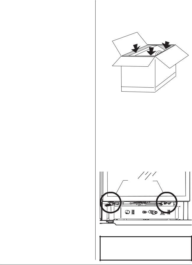
Table of Contents
Specifications ................................... |
4 |
Installation / Service Tools ............ |
5 |
General Information ....................... |
5 |
Safety Information .......................... |
6 |
Installation Requirements |
|
Framing ............................................ |
6 |
Mantel Clearances ........................ |
8 |
Hearth Protection ......................... |
8 |
Vent Requirements ....................... |
9 |
Vertical Termination ................... |
10 |
Horizontal Termination.............. |
11 |
Terminal Clearances .................... |
11 |
Vent Restrictor ............................. |
12 |
Fireplace Assembly |
|
Blower Installation ...................... |
12 |
Gas Connection ............................ |
14 |
Gas Pressure.................................. |
14 |
High Altitude Adjustment ........ |
15 |
Fuel Conversion ............................ |
16 |
Wall Thermostat .......................... |
19 |
Remote Control ............................ |
19 |
Antique Brick Kit .......................... |
20 |
Log Set Installation ..................... |
21 |
Surround Assembly ..................... |
22 |
Double Door Installation ........... |
22 |
System Check................................ |
23 |
Operation ......................................... |
25 |
Maintenance ................................... |
26 |
Glass Replacement ........................ |
26 |
Service Log ....................................... |
27 |
Illustrated Parts Breakdown ....... |
28 |
Replacement Parts List ................. |
29 |
Accessories ...................................... |
30 |
Lighting Instructions .... Back Cover |
|
Unpacking the Fireplace
1.Before you remove the carton, remove the cast iron parts that are packed around the fireplace cabinet.
2.Lift the shipping carton off of the fireplace cabinet.
3.Unpack the Firebox. The Logset is packaged inside the firebox. Remove the Glass Panel Frame to unpack the firebox:
•Locate the right and left spring latches on the underside of the firebox floor. Release each latch by pulling them forward to disengage the frame body.
•Pull the Glass Frame away from the firebox and lift to disengage it from the three steel tabs located at the top of the firebox. Set the glass out of the way.
Do not unpack the logs until you are ready to install them.
Spring Latches
|
BLOWER |
|
BURNER |
|
IGNITOR |
ON |
HI |
|
MANUAL |
|
MANUAL |
|
OFF |
|
OFF |
|
AUTO |
OFF |
AUTO |
HI |
LO |
|
LO |
Pull each Spring Latch to disengage them from the Glass Frame.
PLEASE READ THESE INSTRUCTIONS IN THEIR ENTIRETY AND MAKE THEM AVAILABLE TO ANYONE USING OR SERVICING THIS APPLIANCE.
3
Jøtul GZ 550 DV II Acadia
Direct Vent Gas Fireplace
Manufactured and Distributed by:
Jøtul A.S.A.
Fredrikstad, Norway
Jøtul North America
Portland, Maine
Test Standards
This appliance complies with National Safety standards and is tested and listed by Intertek Testing Services of Middleton, Wisconsin to ANSI Z21.88-2002•CSA 2.33-M02 and CAN/CGA 2.17--M91, CSA P.4.-01.2 for Canada.
DO NOT ATTEMPT TO ALTER OR MODIFY THE CONSTRUCTION OF THE APPLIANCE OR ITS COMPONENTS. ANY MODIFICATION OR ALTERATION WILL VOID THE WARRANTY, CERTIFICATION AND LISTING OF THIS APPLIANCE.
Specifications
Input Rates
Natural Gas
28,000 BTU/hr. maximum input
16,000 BTU/hr. minimum input
Propane
28,000 BTU/hr. maximum input
15,500 BTU/hr. minimum input
Inlet Pressure: |
MIN |
MAX |
|||
Natural Gas: |
5.0 WC (1.24 kPa) |
11.0 WC (2.74 kPa) |
|||
Propane: |
12.0 WC (2.98 kPa) |
14.9.0 WC (3.71 kPa) |
|||
Manifold Pressure: |
|
MIN |
MAX |
||
|
|
|
|
|
|
Natural Gas: |
1.2 WC (.29 kPa) |
3.8 WC (.94 kPa) |
|||
Propane: |
2.9 WC (.72 kPa) |
11.0 WC (2.74 kPa) |
|||
THIS FIREPLACE IS SHIPPED AS A NATURAL GAS FIREPLACE ONLY. IF USE WITH PROPANE IS DESIRED, THE FIREPLACE MUST BE CONVERTED TO USE WITH PROPANE. FOR YOUR CONVENIENCE THIS FIREPLACE IS SHIPPED WITH A PROPANE CONVERSION KIT.
THIS HEATER MUST BE INSTALLED AND MAINTAINED BY A QUALIFIED SERVICE AGENCY.
IN THE COMMENWEALTH OF MASSACHUSETTS, THIS PRODUCT MUST BE INSTALLED BY A LICENSED PLUMBER OR GAS-FITTER.
DO NOT ATTEMPT TO ALTER OR MODIFY THE CONSTRUCTION OF THIS APPLIANCE OR ITS COMPONENTS. ANY MODIFICATION OR ALTERATION WILL VOID THE WARRANTY, CERTIFICATION AND LISTING OF THIS APPLIANCE.
www.nficertified.org
We at Jøtul North America are dedicated to manufacturing the finest quality hearth products you can be assured will give you many years of safe, dependable service.
To ensure your confidence, we recommend that whenever possible, our products be installed and serviced by professionals who are certified by the National Fireplace
Institute (NFI) or, in Canada, by Wood Energy Technical Training (WETT).
4
General Information
IMPORTANT:
SAVE THESE INSTRUCTIONS.
THIS HEATER MUST BE INSTALLED AND MAINTAINED BY A QUALIFIED SERVICE AGENCY.
DO NOT ATTEMPT TO ALTER OR MODIFY THE CONSTRUCTION OF THIS APPLIANCE OR ITS COMPONENTS. ANY MODIFICATION OR ALTERATION WILL VOID THE WARRANTY, CERTIFICATION AND LISTING OF THIS APPLIANCE.
1.The installation and repair of this appliance must be done by a qualified service person. Failure to properly install and maintain this heater could result in an unsafe or hazardous installation, which may result in a fire, explosion, property damage, personal injury or loss of life.
2.This appliance should be inspected before use and at least annually. More frequent cleaning may be required due to excessive lint from carpeting, bedding material, etc. It is imperative that control compartments, burners and circulating air passageways of the appliance be kept clean.
`S’assurer que le bruleur et le compartiment des commandes sont propres. Voir les instructions d’installation et d’utilisation qui accompagnent l’appareil.
3.The installation must conform to local codes. Your local Jøtul authorized dealer can assist you in determining what is required in your area for a safe and legal installation. Some areas require a permit to install a gas burning appliance. Always consult your local building inspector or authority having jurisdiction to determine what regulations apply in your area.
In the absence of local codes, the installation requirements must comply with the current National codes. In the U.S., these requirements are established in the National Fuel Code, ANSI Z223.1.(NFPA 54). In Canada, the codes have been established in CAN/CGA B149 Fuel Installation Code.
Installer l’appareil selon les codes ou reglements locaux, ou, en l’absence de tels reglements, selon les Codes d’installation CAN/CGA-B149.
4.DO NOT OPERATE THIS FIREPLACE IF ANY PART HAS BEEN UNDER WATER.
Immediately call a qualified service technician to inspect the heater and to replace any part of the control system and any gas control which has been under water.
Ne pas se servir de cet appareil s’il a ete’ plonge dans l’eau, completement ou en partie. Appeler un technicien qualifie pour inspecter l’appareil et remplacer toute partie du syste’me de controle et toute commande qui ont ete plonges dans l’eau.
5.Do not operate the fireplace with the glass front removed, cracked or broken. Replacement of the glass should be done by a licensed or qualified service person. Only remove glass for routine service. Always handle glass carefully.
Pour utilisation avec les portes en verre cerifiers aved l’appareil seulemend ou. Ne pas utiliser avec des portes on verre.
6.Notify your insurance company before proceding with installation of this fireplace.
7.This appliance may be installed in an aftermarket permanently located, manufactured (mobile) home, where not prohibited by local codes. This appliance is only for use with the type(s) of gas indicated on the rating plate. This appliance is not convertible for use with other gases, unless a certified kit is used.
Cet appareil peut être installé dans un maison préfabriquée (mobile) déjà installée à demeure si les règlements locaux le permettent. Cet appareil doit être utilisé uniquement avec les types de gas indiqués sur la plaque signalétique. Ne pas l’utiliser avec d’autres gas sauf si un kitde conversion certifié est installé.
Suggested Tools for
Installation and Service
•External regulator (for Propane only)
•Piping which complies with local code
•Manual shutoff valve - T-Handle in MA
•Sediment trap - if required by code
•10mm open end wrench
•1/2”, 7/16” open end wrench
•Phillips head screwdriver
• |
Flat head screwdriver |
•Tee joint |
• |
Pipe wrench |
•Pipe sealant |
• |
1/4” nut driver |
•Torx T20 screwdriver |
• |
Gloves |
•Safety glasses |
• |
Leak test solution |
•Power Drill |
• |
Reciprocating Saw |
|
5

Safety Information
Due to the high operating temperatures this appliance should be located out of traffic and away from furniture, draperies, etc. Maintain proper clearance to combustible mantels and fireplace trim.
Children and adults should be alerted to the hazards of high surface temperatures and should stay away to avoid burns or clothing ignition.
Young children should be supervised while they are in the same room as the Acadia gas fireplace.
Surveiller les enfants. Garder les vetements, les meubles, l’essence ou autres liquides a vapeur inflammables loin de l’appareil.
Clothing or other flammable materials should not be placed ON or NEAR the Acadia gas fireplace.
Never allow any to use the fireplace if they are unfamiliar with its operation.
NEVER store or use gasoline or any other flammable vapors or liquids in the vicinity of the Acadia gas fireplace.
Never burn any solid materials (wood, cardboard, paper, coal, etc.) in this gas fireplace. Use with natural gas or propane fuel ONLY.
Any safety screen, glass or guard removed for servicing the appliance must be replaced prior to operating the appliance.
Do not slam or strike the glass panel.
Wear gloves and safety glases while performing maintenance procedures.
Electrical Hazard
Be aware of electrical wiring locations when cutting holes in walls and ceilings for termination.
The optional Acadia Blower (155630) must be electrically grounded in accordance with local codes or, in the absence of local codes, with the current ANSI/NFPA 70, National Electrical Code or CSA C22.1-Canadian Electrical Code.
The Acadia Blower is supplied with a three-prong (grounding) plug for protection against shock hazard and should be plugged directly into a properly grounded three-prong receptacle. DO NOT CUT OR REMOVE THE GROUNDING PRONG FROM THE PLUG.
Always disconect the power supply when performing routine service on the fireplace.
Installation
Requirements
The GZ 550 DV Acadia Gas Fireplace and its vent system must be installed within a totally enclosed structure. The fireplace must be connected to the specified vent and termination cap outside the building. Do not vent into another room or inside any part of a building. Under no circumstances may the flow of combustion or ventilation air be obstructed.
The approved vent configurations described herein are derived from extensive testing under controlled laboratory conditions. Gas appliance performance can be negatively affected by variables present in the installation environment, i.e: strong prevailing winds, steep roofs, nearby trees, snow accumulation, etc. These conditions should be taken into consideration by the installer and home owner. In such instances, system performance can often be improved by an increase in the vent height or installation of a high wind termination cap.
Placement and Framing
The combustible framing members of the fireplace enclosure may be placed in direct contact with the fireplace cabinet as specified in the illustrations on the following pages. Use the standoffs integrated into the sides and top of the front opening to locate a combustible header and side framing members as shown in the illustrations. See fig. 1.
Electrical Power: If the optional Blower (#155630) will be used, be sure to include provision for a properly grounded, 120 volt house current outlet at the fireplace structure.
Parallel Installation
Although it is possible to place combustible framing members in direct contact with the rear surface of the cabinet, the fireplace must be located forward of the back wall with adequate clearance to accommodate the vent adaptor and subsequent lengths of vent pipe. Consideration must also be given to maintaining a minimum 1 inch (25 mm) clearance between a vertical vent pipe and any combustible materials to the rear of the unit. See Figs. 2, 3, and 4.
Corner Installation
A corner installation will require that the Vent Adaptor be installed in a top exit position. Horizontal terminations will then require use of a 90° elbow. Figs. 5 and 5a show rear termination with 5/8 Simpson Dura-Vent Wall Thimble #1247.
6

Figure 1. Cabinet Dimensions. |
|
|
25” |
||
|
635 mm |
|
|||
|
|
|
|
|
|
|
|
16 1/4” |
|
|
410 mm |
Header Standoff Height: 36 1/2” |
35 3/4” |
|
|
|
|
|
|
900 mm |
35” |
35 3/4” * |
36 1/2” |
890 mm |
910 mm |
921 mm |
4” |
8” |
38” |
100 mm |
200 mm |
970 mm |
NOTE: DO NOT INSTALL CABINET ON FLOOR SURFACE LOWER THAN THE FRONTAL HEARTH SURFACE.
* Wallboard Standoff Height
Figure 2. Minimum horizontal vent allowance through wall.
A
5/8 Vent Adaptor
6” Vent Section
Wall Cutout :
4/6 Pipe - 10”x10” 5/8 Pipe - 11”x11” Observe all vent and termination clearance requirements.
Security Vent:
A = 25 1/4” (645 mm)
Security Termination has no slip adjustibility.
Simpson DuraVent and Amerivent: A = 25 3/4” (660 mm)
A |
38” |
(970 mm) |
Horizontal Vent: Minimum depth accomodates the length of Vent Adaptor and one 6’ vent section through wall construction.
Vent Adaptor: |
5/8 |
A = |
21 3/4” |
Vertical Vent: Minimum depth includes 1 inch clearance between Vent Adaptor and combustible wall construction.
Vent Adaptor: |
5/8 |
4/6 |
A = |
21 1/2” |
20” |
Figure 3. Depth requirement to rear wall.
9” 230 mm
41” 1041 mm
28 1/2”
730 mm
16” 410 mm
56 1/2”
1435 mm
|
Rear Exit |
|
|
|
|
Top Exit |
||
|
16 1/4” |
|
|
|
|
16 1/4” |
||
(415 mm) |
|
|
|
(415 mm) |
||||
|
|
|
|
|
|
|
|
|
|
|
|
|
|
|
|
|
|
|
|
38 3/4” |
|
32 3/4” |
(990 mm) |
|
|
|
|
(830 mm) |
|
16 1/4” |
5/8 Vent |
211/2” |
(413 mm) |
(546mm) |
|
19 1/4” |
4/6 Vent |
20” |
(490 mm) |
(510mm) |
Figure 4. Vent Adaptor orientation.
|
|
|
|
Min. Vent |
|
|
|
|
Clearance |
|
WALL OPENING |
|
|
|
CUSTOM |
5/8 VENT |
|
|
|
11” x 11” |
|
|
|
|
MANTEL |
280 mm x 280 mm |
|
|
|
CABINET |
See text for |
|
2” |
|
|
details. |
|
||
|
|
50 mm |
||
|
|
|
|
48 1/2” |
|
|
|
1232 mm |
|
|
|
|
|
49 1/4” |
|
|
|
|
1232 mm |
|
|
|
|
Minimum |
|
|
43” |
|
mantel |
|
|
1092 mm |
shelf |
|
|
|
|
|
height to |
|
|
|
|
cover vent |
|
|
|
|
wall |
|
|
|
|
thimble |
Figure 5. Corner framing dimensions.
Figure 5a. Corner Installation - 5/8 vent, rear termination.
7
Hearth Protection
The GZ550 Acadia is approved for installation without hearth protection. Combustible materials may be used on the floor directly under and in front of the fireplace. NOTE: The floor surface under the unit must be level with, or higher than, the surface in front of the unit to allow the fireplace Controls Door to fully open.
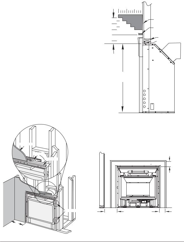
Facing and Clearance Requirements
The following clearance and hearth specifications are the minimum requirements for the GZ550 Acadia gas fireplace. Measure clearances from the steel fireplace cabinet - not the cast iron surround panels. See Figures 6 - 8.
A combustible surface is anything that can burn (i.e. sheet rock, wallpaper, wood, fabrics etc.). These surfaces are not limited to those that are visible and also include materials that are behind non-combus- tibles.
If you are not sure of the combustible nature of a material, consult your local fire officials. “Fire Resistant” materials are considered combustible - they are difficult to ignite, but will burn. “Firerated” sheet rock is also considered combustible.
Maintain the proper clearances to the appliance to allow adequate flow of ventilation air around the fireplace.
Mantel and Trim Clearance |
|
||||
|
|
12” |
8” |
4” |
|
13 1/2” |
12” |
|
MANTEL |
DRYWALL |
|
|
|
|
|||
10 |
1/2” |
|
AREA |
||
9” |
|
|
UPPER TRIM |
||
|
|
|
|
||
7 1/2” |
|
|
|
2 1/2” Max. Depth |
|
|
|
|
|
||
4 1/2” |
|
|
|
HEADER |
|
|
|
|
|
|
|
TOP OF CABINET |
|
|
STANDOFF |
||
|
|
|
|||
|
|
|
|
PANELS |
|
|
|
|
35” |
SURROUNDIRONCAST |
|
|
|
|
|
|
|
Figure 7. Minimum Mantel Clearances. Measure clearances from the top of the fireplace cabinet before installation of the cast iron surround panels.
Wallboard
Header
Standoff |
TOP TRIM |
|
|
|
4 1/2” |
|
|
|
|
1.2 cm |
|
|
SIDEWALL |
GZ550 DV |
TRIMSIDE |
|
|
|
Cabinet |
|
|
Standoffs |
10” |
|
4 1/2” |
|
|
2.55 cm |
|
1.2 cm |
|
10” |
Figure 8. Minimum Side Wall and Trim Clearance. |
|||
Measured from the cabinet, not standoffs or cast iron |
||||
(250 mm) |
||||
Figure 6. Header and Side Standoffs |
panels. |
|
|
|
|
|
|
||
8
Vent Requirements
The GZ550 DV Acadia Gas Fireplace is approved for use with direct vent components produced by the following manufacturers:
•Simpson Dura-Vent Corporation, 5/8 and 4/6 pipe
•Security Vent Ltd. International, 5/8 and 4/6 pipe
•Amerivent Corporation, 4/6 pipe
•Selkirk Metalbestos Corp. MDV Direct Vent Systems
Use vent components from a single vent manufacturer. Do not combine parts from different manufacturers in a single installation.
The vent termination must fall within the shaded area designated in the diagrams in Figures 12 - 14.
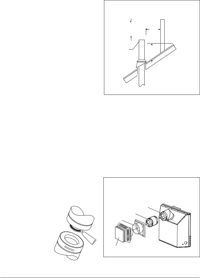
Venting Guidelines
The minimum height for a vertical termination cap must be no less than 7' from the top of the unit. The maximum height must not exceed 35'.
The minimum vent height above the roof or adjacent walls is specified by major building codes. Use the Gas Vent Rule as a general guide. See fig.10. requirements of the approval listing and the manufacturer’s instructions.
Clearance (airspace) between Vent and Combustibles: Top - 2” (51 mm) Sides/Bottom - 1” (25 mm)
Wall Cutout Dimensions:
4/6 Pipe - 10” x 10” |
5/8 Pipe - 11” x 11” |
Any horizontal run must rise 1/4” per foot.
Install venting in accordance with the vent manufacturers’ instructions. Never modify any venting component, or use any damaged venting product.
THE GAS APPLIANCE AND VENT SYSTEM MUST BE VENTED DIRECTLY TO THE OUTSIDE OF THE BUILDING. DO NOT CONNECT VENT TO A
CHIMNEY SERVING A SOLID FUEL OR ANOTHER GAS APPLIANCE.
Joint Sealing Requirement:
Apply a 1/8” bead of hightemperature (750°F) sealant to the male section of the inner vent pipe. See fig. 9. The cement should seal
the inner pipe from the outer pipe.
SEAL  ANT
ANT
Figure 9. Seal each inner joint before joining pipe.
|
|
|
Horizontal Overhang |
all |
|||||||||||
|
|
|
|
|
|
|
|
|
|
|
|
|
|
|
|
18”. |
|
|
|
18”. |
W |
||||||||||
|
|
|
Vertical |
||||||||||||
min. |
|
|
|
|
|
|
|
|
|
|
|||||
|
|
|
min. |
||||||||||||
|
|
|
|
||||||||||||
|
|
|
|
|
|
|
|
|
|
|
|
|
|
|
Lowest Discharge |
|
|
|
|
|
|
|
|
|
|
|
|
|
|
|
|
|
|
|
|
|
|
|
|
|
|
|
|
|
|
|
Opening |
Termination |
|
|
|
|
|
|
|
|
|
|
|||||
|
|
|
|
|
|
|
|
|
|
|
|||||
Cap |
|
|
|
|
|
|
|
|
|
|
|
||||
|
18” min. |
|
|||||||||||||
|
|
|
|
|
|
|
|||||||||
|
|
|
|
|
|
|
|
|
|
|
|
|
|
|
|
|
|
|
|
|
|
|
|
|
|
|
|
|
|
|
|
|
|
|
|
|
|
|
|
|
|
|
|
|
|
|
|
|
|
|
|
|
|
|
|
|
|
|
|
|
|
|
|
Figure 10. Gas Vent Height Rule: Vertical vent termination height above roof.
Do not recess the vent terminal into a wall or siding.
Inspect the vent system annually for blockage and deterioration. If the vent-air intake system is disassembled for any reason, reinstall according to the instructions provided for initial installation.
Installation of any components not manufactured or approved by Jøtul or failure to meet all clearance requirements will void all warranties and may result in property damage, bodily injury, or loss of life.
IN DESIGNING THE VENT SYSTEM, DO NOT
COUNT THE 45° ELBOW CONNECTED TO THE
VENT COLLAR AS AN ELBOW.
45° Elbow
6” Vent Section
Wall Support
Wall Termination
Figure 11. Typical minimum horizontal vent configuration - 5/8 Simpson DuraVent. Do not use 4/6 pipe in this configuration.
9
35 |
|
|
|
|
Restrictor |
|
|
|
Fully Closed |
|
|
30 |
|
|
|
Height in Feet From Vent Collar |
Restrictor |
|
|
|
2/3 Closed |
|
|
18 |
|
|
|
|
Restrictor |
|
|
|
1/3 Closed |
|
|
10 |
|
|
|
9 |
Restrictor |
|
|
MinimumHeight 7 |
Open |
|
|
|
Both |
||
|
|
||
Max.Two |
5/8 Vent |
|
|
4/6 Vent |
|
|
|
Elbows - |
|
|
|
|
|
|
|
90° or 45° |
|
|
|
|
7 |
10 |
12 |
Horizontal Run in Feet
Figure 12. Vent Window for vertical termination using 5/8 or 4/6 pipe.
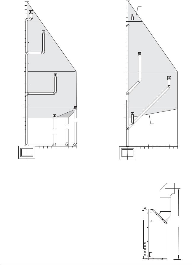
Vertical Termination
The vent must terminate within the shaded area designated on the graphs in Figs. 12 and 13.
•Maximum Elbows - Two 90° or Two 45° (Do not count the first elbow off the vent collar.)
•Use the restrictor settings indicated in the graph as general guide. The specific characteristics of your installation may require different settings.
Horizontal Termination
The vent must terminate within the shaded area designated in Figs. 15 and 16. (Do not count the first elbow off the vent collar.)
•Max. Elbows - One 90° or one 45°.
•Use of 4/6 pipe requires a minimum 1 foot rise.Fig.16.
35
Restrictor
Fully Closed
30 

Restrictor
2/3 Closed
18
Feetin CollarVent 

 Height From Restrictor 1/3 Closed
10 |
|
9 |
|
7 |
Restrictor |
|
|
|
Open |
Max.Two 45°
Elbows
5 |
10 |
12 |
Horizontal Run in Feet
Figure 13. Vent Window for offset vertical termination using 5/8 or 4/6 pipe.
Figure 14. Minimim centerline for horizontal termination of 4/6 pipe
52” (990 mm)
10
 Loading...