

Page 1
Jøtul F 100 USA
Jøtul F 100 USA
Installation and Operating Instructions for USA and Canada
Keep these instructions for future reference.
Page 2
USA/Canada
Installation and Operation Instructions for USA/Canada
Installation et fonctionnement pour Canada
Safety notice: If this solid fuel room heater is not properly installed, a house fire may result.
For your safety, follow the installation directions. Contact local building or fire officials about
restrictions and installation inspection requirements in your area. Save these instructions for
future reference.
Avis de sécurité: Une installation non appropriée de ce poêle de chauffage risque de provoquer
un incendie. Assurez votre sécurité en respectant les directives d’installation suivantes.
Consultez les autorités locales du bâtiment ou de la prévention des incendies au sujet des
restrictions et exigences relatives aux inspections d’installations dans votre région.
Tested and listed by ITS, Intertek Testing Services, Middleton, Wisconsin.
Tested to U.S. Standards: ANSI/UL 1482, Canadian Standards: CAN/ULC-S627-M93
Standards
The Jøtul F 100 USA woodstove has been tested and listed
to:
U.S. ANSI/UL 1482
Canada: CAN/ULC-S627-M93
Tests performed by:
ITS, Intertek Testing Services, Middleton, WI
Manufactured by:
Jøtul AS, P.O. Box 1411, N-1602 Fredrikstad, Norway
Distributed by: Jøtul North America, P.O. Box 1157
100 Riverside Street, Portland, ME 04104
This heater meets the U.S. Environment Protection
Agency’s Emissions limits for wood heaters
manufactured and sold after July 1, 1990.
Under specific test conditions, this heater has shown heat
output at rates ranging from 7,700 to 27,000 BTU’s per
hour.
The Jøtul F 100 USA woodstove is only listed to burn wood.
Do not burn any other fuels.
Check Building Codes
When installing, operating and maintaining your
Jøtul F 100 USA woodstove, follow the guidelines
presented in these instructions, and make them available
to anyone using or servicing the stove.
Your city, town, county or province may require a building
permit to install a solid fuel burning appliance.
In the U.S., the National Fire Protection Association’s Code,
NFPA 211, Standards for Chimneys, Fireplaces, Vents and Solid
Fuel Burning Appliances, or similar regulations, may apply
to the installation of a solid fuel burning appliance in your
area.
In Canada, the guideline is established by the CSA
Standard, CAN/CSA-B365-M93, Installation Code for Solid-
Fuel-Burning Appliances and Equipment.
Always consult your local building inspector or authority
having jurisdiction to determine what regulations apply
in your area.
Read this entire manual before you install and use your
new room heater.
Save these instructions and make them available to
anyone using or servicing the stove.
2
Page 3
USA/Canada
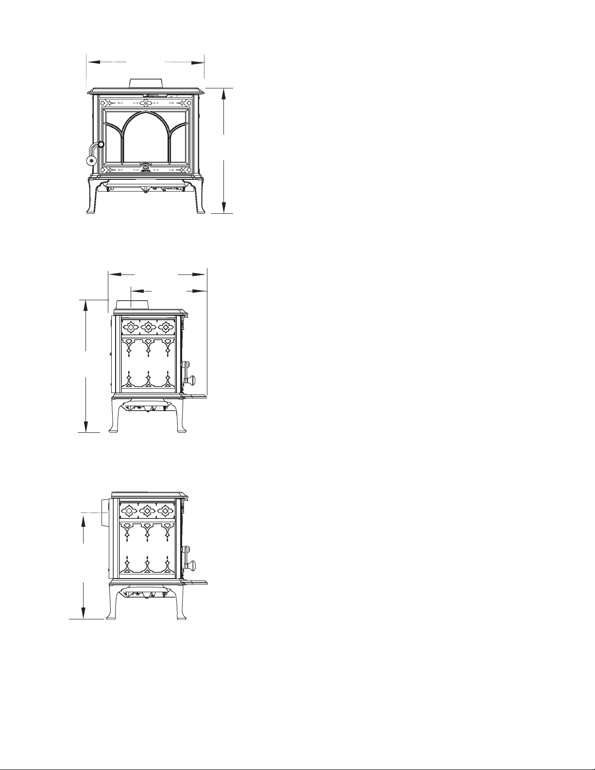
24”
610 mm
20 3/4”
527 mm
17 1/2”
445 mm
347 mm
13 1/2”
22 1/2”
570 mm
Table of Contents
Standards and Safety Notices
Standards / Codes....................................................................... 2
Safety Notices ............................................................................... 4
Installation
Flue Collar Installation ............................................................... 4
Chimney Connector ...................................................................5
Chimney Requirements
Masonry Chimneys ..................................................................... 6
Prefabricated Chimneys ............................................................ 6
Chimney Height........................................................................... 6
Wall Pass-Throughs ..................................................................... 7
Connecting to the Chimney
Masonry Chimney....................................................................... 8
Hearthmount / Fireplaces......................................................... 8
Prefabricated Chimneys ............................................................ 9
Clearances to Combustibles
Floor Protection ........................................................................... 9
Clearances to Walls and Ceilings............................................. 10
Alcove Installation ....................................................................... 10
Clearance Chart ............................................................................ 12
Clearance Diagrams .................................................................... 13
18 1/2”
469 mm
Rear Exit
Centerline
Operation
Wood Fuel ..................................................................................... 14
Controls.......................................................................................... 14
Break-in Procedure...................................................................... 14
Starting / Maintaining the Fire ............................................... 15
Formation of Creosote ..............................................................15
Maintenance
Ash Removal ................................................................................. 16
Glass Care ...................................................................................... 16
General Maintenance
Gaskets ........................................................................................... 17
Accessories
Stove-top Thermometer ........................................................... 17
Flue Collar Heat Shield .............................................................. 17
Illustrated Parts List ........................................................18-19
3
Page 4

USA/Canada
Safety Notices
• Burn solid wood fuel only
• Do not use chemicals or fluids to start the fire.
Do not burn garbage or flammable fluids.
• If this room heater is not properly installed, a
house fire may result. To reduce the risk of fire,
follow the installation instructions. Failure to
follow these instructions may result in
property damage, bodily injury, or loss of life.
• Contact the local building or fire officials about
restrictions and installation inspection
requirements in your area.
• Do not connect this stove to any air
distribution duct or system.
• Extremely hot while in operation! Keep
children, clothing and furniture away. Contact
will cause skin burns.
• Install smoke detectors in the living areas and
bedrooms of your home. Test them regularly and
install new batteries twice annually.
When installed in the same room as the stove, a
smoke detector should be located as far from the
stove as possible to prevent it from sounding
when adding fuel to the fire.
• Avoid creating a low pressure condition in the
room where the stove is operating. Be aware
that operation of an exhaust fan or clothes
dryer can create a low pressure area and
consequently promote flow reversal through
the stove and chimney system. The chimney
and building, however, always work together
as a system - provision of outside air, directly or
indirectly to an atmospherically vented
appliance will not guarantee proper chimney
performance. Consult your local Jøtul
authorized dealer regarding specific
installation/performance issues.
• Jøtul recommends that this stove be installed
by a professional solid fuel technician or that
you consult one if you do the work yourself. Also,
consult your insurance company regarding any
other specific requirements.
Installation
If this solid fuel room heater is not properly installed, a
house fire may result. For your safety, follow the
installation directions. Contact the local building or fire
officials about restrictions and installation inspection
requirements in your area.
Your local officials have final authority in determining if a
proposed installation is acceptable. Any requirement by
the local authority having jurisdiction that is not
specifically addressed in this manual, defaults to NFPA
211, and local codes in the U.S. or in Canada, CAN/CSAB365-M and local codes.
Assembly Before Installation
Unpack the Stove
Inspect the stove for damage. Contact your dealer
immediately if any damage is found. Do not install the
stove if any damage is evident.
Contents:
• Ash Lip
• Door Handle
• Hardware Bag
- Flue Collar gasket
- 6” Pipe Adaptor
Flue Collar Installation
The Flue Collar is oriented in the Top Exit position. Apply
the gasket to the collar before installing the chimney
connector.
Position Reversal
Follow this procedure to change the collar to a Rear Exit
position if appropriate.
1. Remove the Flue Collar by reaching through the
opening and removing the two bolts that secure it to
the top plate.
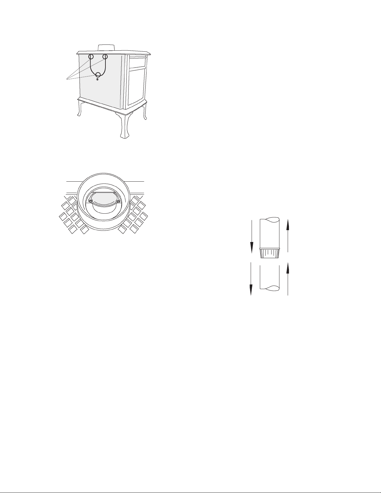
2. Using tin snips, cut out the panel from the Rear Heat
Shield for the Flue Collar to pass through. See fig. 1.
3. Remove the two screws that attach the Coverplate to
the rear outlet. Hold onto the Coverplate while
removing the second screw so that it does not fall
out. See fig. 2.
4. Using the same screws, attach the Flue Collar to the
rear outlet and the Coverplate to the Top Plate.
5. Install the Flue Collar gasket. Remove the protective
paper from the adhesive side and apply the gasket to
the inside of the Flue Collar.
4
Page 5
Cut at
these
points
Figure 1. Rear flue collar cut-out.
USA/Canada
• Secure all connector joints with three sheet metal
screws. The connection to the stove flue collar takes
two sheetmetal screws.
• For the best performance, the chimney connector
should be as short and direct as possible, including no
more than two 90° elbows.
• The maximum vertical run of single wall stovepipe
should not exceed 10 ft. (305 cm).
• The maximum horizontal run should not exceed 3 ft.
(92 cm) with a 1/4” rise per foot. Under no circumstance
should horizontal pipe be allowed to slant down toward
the chimney.
• No part of the chimney connector may pass through
an attic or roof space, closet or other concealed space,
or through a floor or ceiling. All sections of the chimney
connectors must be accessible for cleaning. Where
passage through a wall or partition of combustible
construction is desired, the installation must conform
with NFPA 211 or CAN/CSA-B365, and is also addressed
in this manual.
• Do not connect this stove to a chimney flue servicing
another appliance.
Figure 2. Remove the Rear Flue Outlet Coverplate.
Install the Ashlip
Attach the ashlip to the front by engaging the center tab
with the slot located under the front door.
Assemble the Door Knob
Locate the white washer between the handle and the
knob.
Chimney Connector
Use 6” single wall or listed 6” double-wall stovepipe to
connect the stove to the chimney. Single wall stovepipe
must be black iron or stainless steel and have a minimum
thickness of 24 gauge. Do not use aluminum or galvanized
steel pipe for chimney connection - these materials are
not suitable for use with solid fuel.
Follow these guidelines regarding chimney connector
construction:
• Do not use chimney connector as a chimney. It is
intended only for use as a connection device.
• Each connector section must be oriented with the male
(crimped) end pointing toward the stove. See fig. 3.
To war d
Stove
Figure 3. Chimney connector orientation.
Flue Gas
Direction
5
Page 6
USA/Canada
Chimney Requirements
There are two types of chimneys suitable for the Jøtul
F 100 USA :
1. A code-approved masonry chimney with a ceramic tile
or listed steel flue liner.
2. A prefabricated chimney complying with the
requirements for Type HT (2100°F) chimneys per UL
103 or ULC S629.
The chimney size should not be less than the crosssectional area of the flue collar, and not more than three
times greater than the cross-sectional area of the flue
collar.
When selecting a chimney type and the location for the
chimney in the house, keep this in mind: It is the chimney
that makes the stove work, not the stove that makes the
chimney work. This is because a chimney actually creates
a suction, called “draft” which pulls air through the stove.
Several factors affect draft: chimney height, crosssectional area (size), and temperature of the chimney, as
well as the proximity of surrounding trees or buildings.
A short exterior masonry chimney will give the poorest
performance because it will be difficult to warm the flue
and sustain the temperatures necessary to maintain draft
strength. In extremely cold climates, it may be necessary
to reline the chimney or extend the height to help establish
draft.
A tall, interior masonry chimney is easier to keep warm
and will perform the best under a variety of weather and
environmental conditions.
The following guidelines give the necessary chimney
requirements based on the national code (ANSI-NFPA 211
for the US. And CSA CAN-B365 for Canada). However,
many local codes differ from the national code to take
into account climate, altitude, or other factors. Your local
building inspector is the final approving authority. Consult
them prior to installation.
There must be at least 1/2” (12.7 mm) air space between
the flue liner and chimney wall.
• The fireclay flue liner must have a nominal size of 8” X
8” (20 cm x 20 cm), and should not be larger than 8”X
12” (20 cm x 30 cm). A round fireclay liner must have a
minimum inside diameter of 6” (15 cm) and maximum
inside diameter of 8” (20 cm). A larger chimney should
be relined with an appropriate code approved liner.
• Brick or modular block must be a minimum of 4” (10
cm) nominal thickness. Stone construction must be at
least 12” (30 cm) thick.
• A newly-built chimney must conform to local codes, or,
in their absence, must comply with national
regulations.
• An existing chimney must be inspected by a
professional licensed chimney sweep, fire official, or
code officer to ensure that the chimney is in proper
working order.
• No other appliance may be vented into the same flue.
• An airtight clean-out door should be located at the
base of the chimney.
Prefabricated Chimneys
A prefabricated metal chimney must be tested and listed
for use with solid fuel burning appliances. High
Temperature (HT) Chimney Standard UL 103 for the U.S.
and High Temperature Standard ULC S-629 for Canada.
The manufacturer’s installation instructions must be
followed precisely. Always maintain the proper clearance
to combustibles as established by the pipe manufacturer.
This clearance is usually a minimum of 2”, although it may
vary by manufacturer or for certain chimney components.
Chimney Height
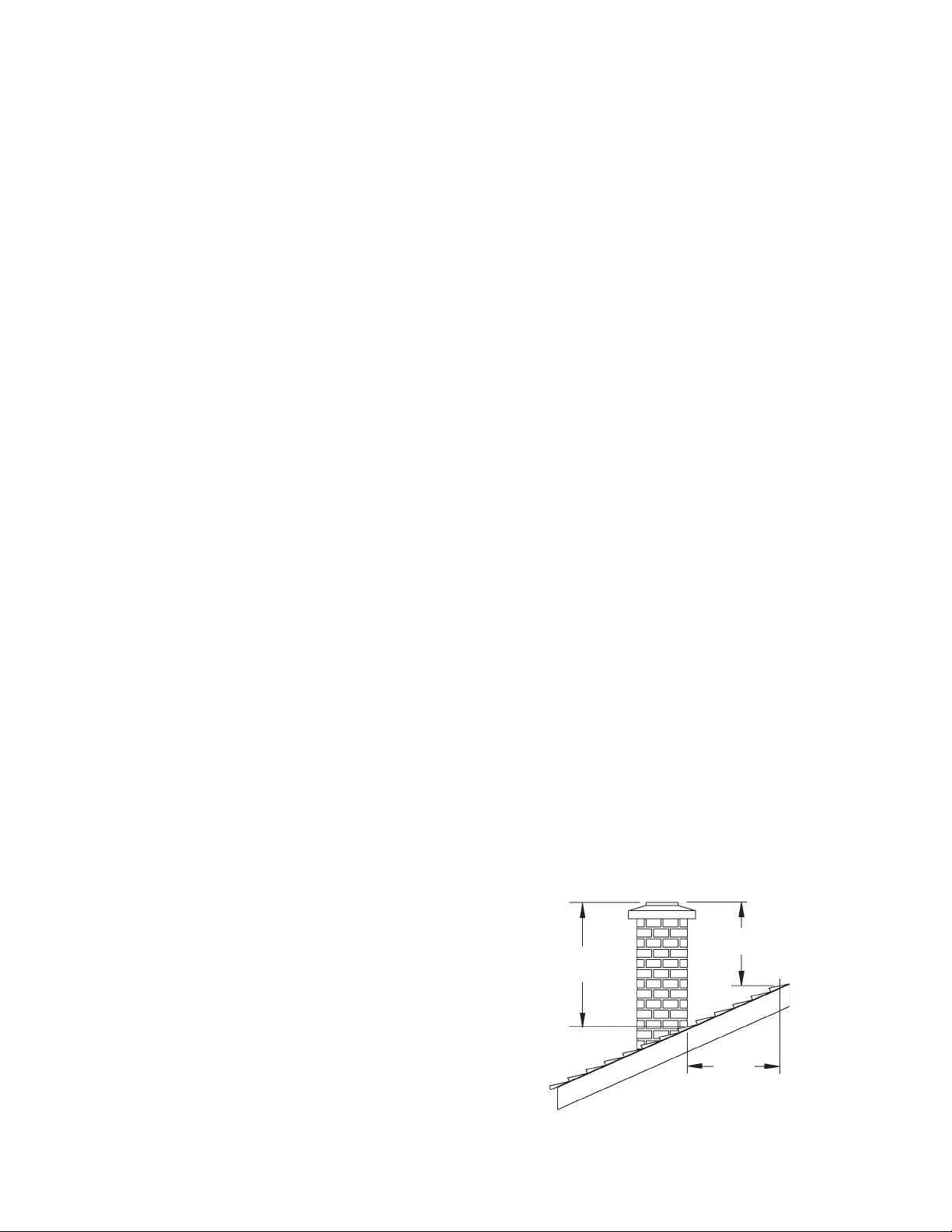
The chimney must be at least 3 feet (92 cm) higher than
the highest point where it passes through the roof and at
least 2 feet (61 cm) higher than the highest part of the
roof or structure that is within 10 feet (3.05 m) of the
chimney, measured horizontally. See figure 4.
Do not connect the stove to any air distribution duct or
system.
Masonry Chimneys
When installing the Jøtul F 100 USA into a masonry
chimney you must conform to all of the following
guidelines:
• The masonry chimney must have a fireclay liner or
equivalent, with a minimum thickness of 5/8” (14 mm)
and must be installed with refractory mortar.
6
2’
3’
91.5 cm
Figure 4. Chimney Height Requirement.
61 cm
10’
305 cm
Page 7

USA/Canada
Chimneys shorter than 14 feet (4.27 m) may not provide
adequate draft. Inadequate draft can result in smoke
spillage when loading the stove, or when the door is open.
Poor draft can also cause back puffing (ignition of gas
build-up inside the firebox) and sluggish performance.
The minimum height does not, in itself, guarantee proper
chimney performance.
Excessive chimney height can promote over-strong draft
resulting in high stove temperatures and short burn times.
Excessive draft can be corrected by installing a butterfly
damper. Your Jøtul dealer is an expert resource to consult
regarding draft issues or other performance-related
questions.
Wall Pass-Throughs
In the U.S.
The National Fire Protection Association’s publication,
NFPA 211, Standard for Chimneys, Fireplaces, Vents and Solid
Fuel Burning Appliances permits four methods for passing
through a combustible wall. Before proceeding with any
method be sure to consult with your local building officials
to discuss any local code requirements.
Common Method:
See Figure 5. Remove all combustible materials from the
pass-through area ( around the chimney connector), a
minimum 12” (30.5 cm). A 6” (15.2 cm) diameter connector
will require a 31” x 31” (78.7 x 78.7 cm) square opening.
The opening must be filled with at least 12” (30.5 cm) of
brick around a fireclay liner. The liner must be ASTM C35
or equivalent, having a minimum wall thickness of 5/8”
(16 mm).
The Pass-through must be at least 18” (45.7 cm) from
combustible ceiling materials.
It will be necessary to cut wall studs, install headers, and
construct a sill frame to maintain the proper dimensions
and to support the weight of the brick.
The bricks must be solid brick with a minimum of 3 ½
inches thick (nominal 4”/ 102 mm).
Refractory mortar must be used at the junction of the
chimney and the pass-through liner. The pass-through liner
must not penetrate the chimney liner beyond the inner
surface of the chimney liner. Use extreme care when
constructing the hole in the chimney liner as the tiles can
shatter easily.
In Canada
The installation must conform to CAN/CSA-B365,
Installation Code for Solid Fuel Burning Appliances and
Equipment. Before proceeding be sure to consult your
local building inspector.
Common Method:
This method requires the removal of all combustible
materials from at least 18” (45.7 cm) around the chimney
connector’s proposed location. A 6” round liner requires
a minimum opening 43” x 43” (109.2 x 109.2) square.
Clearance to
Chimney
Header
12”
30.5 cm
Pass through
construction:
12” Brick from
thimble to
combustibles
Thimble: 5/8”
Fireclay Liner or
equivalent
Sill / Support
12”
Figure 5.
Masonry Wall Pass-through.
Flue LinerWood Stud 2”
Locate the pass-through at least 18” from combustible
ceiling materials.
The space that is cleared of combustible materials must
remain empty. Sheet metal panels can be used to cover
the area. However, when using a panel on both sides of
the wall, each cover must be installed on noncombustible
spacers at least 1” from the wall. If one panel of sheet
metal is to be used it may be installed flush to the wall.
See section 5.3.1 and 5.3.2 of CAN/CSA - B365-M91. Consult
your local building inspector, authorized Jøtul Dealer, NFPA
211 in the U.S. or CAN/CSA-B635 in Canada for other
approved wall pass-through methods.
7
Page 8

USA/Canada
Connecting to the Chimney
Masonry Chimney
When installing a Jøtul F 100 USA into a masonry chimney
through a “thimble” (the opening through the chimney
wall to the flue), the thimble must consist of ceramic tile
or steel and be securely cemented in place.
The chimney connector/stove pipe must slide completely
inside the thimble to the inner surface or the flue liner. It
may be necessary to make use of a thimble sleeve (a pipe
with a slightly smaller diameter than standard stove pipe).
See figure 6.
Connector pipe must
be flush with the
inside of the flue tile
Chimney
Connector
Pipe
Thimble
Flue Tile
Connector
extends into
the first flue
Damper is
sealed with a
steel plate
and sealant
Figure 7. Hearthmount Installation.
The inside area of the flue liner must not be less than the
area of the stove flue collar and cannot be more than
three times greater than the cross sectional area of the
stove flue collar.
If the chimney liner is too large to accommodate the stove,
an approved relining system must be installed to resize
the flue.
Figure 6. Masonry Chimney Thimble.
The connector pipe or thimble sleeve must not protrude
into the flue liner or otherwise restrict draft.
Use refractory cement to seal the seam between the
chimney connector, sleeve, and thimble.
Do not connect this stove to a chimney flue servicing
another appliance of any kind.
Hearthmount into a Masonry
Fireplace
The Jøtul F 100 USA may be installed into a masonry
fireplace with a minimum opening height of 22 1/2”
(572 mm).
Building code requires that the fireplace damper plate be
removed or securely fixed in the open position. A
connector pipe must then extend from the stove’s flue
exit through the damper area of the fireplace and into
the chimney tile liner. See figure 7.
A new sheet metal damper block-off plate must be
installed around the connector pipe at the damper frame
and sealed with the proper sealant (usually High-Temp
Silicone).
8
Page 9

USA/Canada
Prefabricated Chimneys
When connecting the Jøtul F 100 USA to a prefabricated
metal chimney always follow the pipe manufacturer’s
instructions and be sure to use the components that are
required. This usually includes a “smoke pipe adapter”
that is secured to the bottom section of the metal chimney
and allows the chimney pipe to be secured to it with two
sheet metal screws. See figure 8.
Listed Cap
Storm
Flashing
Specified
Combustible
Chimney
Listed
to
Attic
Insulation
Ceiling
Clearance to Combustibles
2”(5 cm)
A
A
B
37”U.S & CAN
Figure 9. Hearth Protection.
A: 8” (21 cm)
B: 16” (US)
B: 46 cm (Can)
38” (97 cm) U.S
A
40”(102 cm) CAN
Floor
Figure 8. Prefabricated Listed Type HT Chimney.
Floor Protection
The Jøtul F 100 USA requires one of the following forms
of hearth protection:
1. Any UL, ULC or WH listed hearth board. (No bottom
heat shield required).
2. Any noncombustible material with use of the bottom
heat shield.
All forms of protection must include a noncombustible
surface extending forward from the glass panel at least
16” for the U.S., or 18” (46cm) for Canada. Protection
must extend 8” (21 cm) from the sides and rear for both:
the U.S. and Canada.
This will result in a minimum floor protection of 37” W x
38” D for the U.S. or 37” W x 40” D for Canada. See
figure 9.
In a rear vent installation, the floor protection must also
extend under the stove pipe a minimum of 2” (5 cm)
beyond either side of the pipe. See figure 9.
9
Page 10

USA/CANADA
Clearances to Walls and Ceilings
The clearances listed and diagramed in this manual have
been tested to UL and ULC standards and are the
minimum clearances to combustible materials
specifically established for the Jøtul F 100 USA.
A combustible surface is anything that can burn (i.e. sheet
rock, wall paper, wood, fabrics etc.). These surfaces are
not limited to those that are visible and also include
materials that are behind noncombustible materials.
If you are not sure of the combustible nature of a material,
consult your local fire officials.
Remember: “Fire Resistant” materials are considered
combustible; they are difficult to ignite, but will burn. Also
“Fire-rated” sheet rock is also considered combustible.
Contact your local building officials about restrictions
and installation requirements in your area.
See pages12-13 for complete clearance requirements and
diagrams.
Notice:
accessories that permit clearance reduction. Use only
those accessories that have been tested by an
independent laboratory and carry the laboratory’s testing
mark. Be sure to follow all of the manufacturer’s
instructions.
Many manufacturers have developed woodstove
60”
153 cm
55”
140 cm
Figure 10. Alcove without Wall Protection.
Using Shields to Reduce Clearances
Chimney Connector Heat Shields:Chimney Connector Heat Shields:
Chimney Connector Heat Shields: Use only connector
Chimney Connector Heat Shields:Chimney Connector Heat Shields:
heat shielding listed for use with solid fuel heaters. The
connector heat shield must begin 1” above the lowest
exposed point of the connector pipe and extend vertically
a minimum of 25” (640 cm) above the top surface of the
stove.
Double Double
Double
Double Double
acceptable alternative to connector pipe heat shields.
When using double wWhen using double w
When using double w
When using double wWhen using double w
Shield Kit 154997 must be installed on the stove.Shield Kit 154997 must be installed on the stove.
Shield Kit 154997 must be installed on the stove.
Shield Kit 154997 must be installed on the stove.Shield Kit 154997 must be installed on the stove.
WW
W
WW
through the use of wall mounted protection:
In In
In
In In
Fireplaces, Vents and Solid Fuel Burning Appliances
acceptable materials, proper sizing and construction
guidelines.
In Canada,In Canada,
In Canada,
In Canada,In Canada,
for Solid-Fuel Burning Appliances and Equipment
for acceptable materials, proper sizing and
construction guidelines.
WW
W
WW
all-Mounall-Moun
all-Moun
all-Mounall-Moun
the Uthe U
.S.S
the U
.S
the Uthe U
.S.S
all Call C
onneconnec
tt
oror
all C
onnec
all Call C
onneconnec
ted Prted Pr
ted Pr
ted Prted Pr
..
r r
efef
er er
tt
.
r
..
r r
o No N
ef
er
t
o N
efef
er er
tt
o No N
refer to CAN/CSA-B365, refer to CAN/CSA-B365,
refer to CAN/CSA-B365, Installation Code
refer to CAN/CSA-B365, refer to CAN/CSA-B365,
::
t
or
: Listed double wall pipe is an
tt
oror
::
all call c
onneconnec
tt
oror
,,
all c
onnec
all call c
onneconnec
otecotec
tion:tion:
otec
tion: When reducing clearances
otecotec
tion:tion:
FPFP
A 211A 211
FP
A 211, Standard for Chimneys,
FPFP
A 211A 211
t
or
tt
oror
Flue C Flue C
,
Flue C
,,
Flue C Flue C
ollar Heaollar Hea
ollar Hea
ollar Heaollar Hea
, also
, for
48”
122 cm
41”
104 cm
Figure 11. Alcove with Wall Protection.
tt
t
tt
Alcove Installation
The Jøtul F 100 USA can be installed in an Alcove as
diagrammed in figures 10 and 11.
1. The stove must be installed with listed double wall
pipe.
2. In a protected alcove installation both side walls and
rear wall must be protected per NFPA 211 or CAN/
CSA-B365. The wall protection must be elevated 1” (25
mm) from the floor and spaced at least 1” (25 mm) off
the combustible wall, using noncombustible spacers,
to allow for air circulation behind the shield.
3. The height of the wall protection including the bottom
air space must be 48” (121 cm).
4. Alcove floor protection must consist of a UL/ULC or
WHI listed hearth pad or a non combustible material
with a minimum R value of 2.0.
10
Page 11

5. Minimum ceiling height in an unprotected installation,
off the top of the stove is 60”(153 cm). The minimum
ceiling height off the top of the stove in a protected
ceiling installation is 48” (122 cm).
Clearances to Fireplace Mantels and
Surround Trim
See the Clearance Chart on page 12 for approved
clearances to combustible materials that may be part of
fireplace construction. See also fig. 12 on page 12
USA/CANADA
11
Page 12

USA/CANADA
Jøtul F 100 USA Clearance Chart
All clearances established with included stove rear heat shield installed.
Stove Unprotected Surface Protected Surface
Clearances Installation per NFPA211 or CAN/CSA -B365-M93
Side Rear Corner* Side Rear Corner*
ABJ C D K
Single-wall Connector 15” 11” 10” 10” 5” 7”
Single-wall Connector EFLG HM
with Connector Shields 17” 8” 10” 10” 5” 7”
or Double-wall Connector* 432 mm 203 mm 254 mm 254 mm 127 mm 178 mm
Chimney Connector Unprotected Surface Protected Surface
Vertical Installation per NFPA211 or CAN/CSA-B365-M93
Single-wall Connector 11” (280 mm) 6” (153 mm)
Single-wall Connector
with Connector Shields 8” (203 mm) 5” (127 mm)
or Double-wall Connector*
381 mm 280 mm 254 mm 254 mm 127 mm 178 mm
Chimney Connector Unprotected Surface Protected Surface
Horizontal Installation per NFPA211 or CAN/CSA-B365-M93
Single-wall Connector 18” (457 mm) 12” (305 mm)
Double-wall Connector* Manufacturer’s Listing Manufacturer’s Listing
* Double Wall Connector must be installed with Flue Collar Heat Shield Kit 154996.
Mantel and Trim Clearances
Top and Side Trim is 1" thick or less
Maximum Mantel depth 12"
Figure 12
Unprotected Surfaces Protected Surfaces
A. Mantel 22” (560 mm) 9” (230 mm)
B: Top Trim 17” (430 mm) 8” (200 mm)
C: Side Trim 14” (355 mm) 7” (430 mm)
12
Page 13

Unprotected Surface
Parallel To The Wall
Protected Surface
Parallel To The Wall
PER NFPA 211 or
CAN/CSA-B365
Connector heatshields and double wall pipe must be a listed product.
Unprotected Surface
Corner Installation
B
A
F
E
Important:
Always follow the manufacturer’s instructions.
D
C
H
G
13
Page 14

USA/Canada
Operation
Please read the following section before building a fire in
your new Jøtul F 100 USA.
Use Solid Wood Fuel Only
First this stove is designed to burn natural wood only.
Wood that has been air-dried for a period of 6 to 14 months
will provide the cleanest, most efficient heat.
Do not burn:
• Coal • Treated or painted wood
• Garbage • Chemical Chimney cleaners
• Cardboard • Colored paper
• Solvents • Any synthetic fuel or logs
• Drift wood • Laminated wood
The burning of any of these materials can result in the
release of toxic fumes. Never use gasoline, gasoline-type
lantern fuel, kerosene, charcoal lighter fluid, or similar
liquids to start or “freshen-up” the fire. Always keep such
liquids away from the heater at all times.
Important: Never build or allow the fire to rest directly on
the glass panels. The logs should always be spaced at
least one inch from the glass to allow for proper air flow
within the firebox.
Controls on the Jøtul F 100 USA
Combustion air is controlled by the Primary Air Lever,
located above the Loading Door. The lever actuates a
shutter over the air inlet which regulates the volume of
primary air entering the firebox and controls heat output
and burn time. See fig. 13.
When first starting or reviving the fire: the primary control
lever should be at the far right position, which allows the
maximum amount of air into the stove. The greater the
amount of air entering the stove, the hotter and faster
the fire will burn.
Moving the lever to the left reduces the airflow into the
stove which prolongs the fire at a lower heat output.
Air Flow / Performance
Primary air enters the firebox directly above the glass
panel on the door. The incoming air creates a turbulent
barrier or “airwash” between the glass and the fire.
Reducing the flow of primary air directly reduces the
effectiveness of the airwash. Determining the primary
air setting for the best overall performance for your
particular needs and installation will best be established
over time through trial and error.
Break-In Procedure
Figure 13. Slide the Air Control Lever to the right to increase
combustion air and to the left to decrease combustion air.
The Jøtul F 100 USA is constructed of cast iron and high
temperature furnace cement. This type of construction
requires the stove to be “broken-in” gradually so that
heat expansion does not occur too quickly and cause
damage. The following steps describe the proper breakin procedure for the Jøtul F 100 USA. Use a magnetic stovetop thermometer to monitor stove temperature, placed
directly on the top plate.
1 Light a small fire of newspaper and kindling. Only
allowthe stove to reach a maximum surface
temperature of 200°F (93° C). Burn for approximately
1 hour.
2 Allow the stove to cool to room temperature.
3 Light a second fire, allowing the stove to reach a
maximum temperature of 300°F (149°C) for 1 hour.
4 Cool the stove to room temperature.
5 Light a third fire and gradually allow the stove to reach
a surface temperature of 400°F (204°C)
6 Cool stove to room temperature. This completes the
“break-in” procedure.
Note: If the temperature exceeds the limit during any
break-in fire, move the primary air control lever all the
way to the left to shut off the air supply completely. It is
normal that the stove top temperature will continue to
climb until the fuel burns down somewhat. Once the fire
14
Page 15

USA/Canada
is out and the stove has cooled to room temperature,
continue the break-in procedure. Never attempt to reduce
the temperature by removing burning logs from the fire.
Breakin Odors: It is normal for a new painted stove to
emit odor and smoke during the first few fires. This is
caused by curing of the high temperature paint and will
diminish with each fire. Open a window or door to provide
additional ventilation to alleviate this condition.
Enamel Stove: You may notice moisture condensation on
the surface ot he stove during the first few fires. To
avoid permanent spotting of the surface, use a soft towel
to wipe the moisture away.
Starting and Maintaining a Fire
Burn only solid wood directly on the bottom grate of the
stove. Do not elevate the fire in any way.
1. With the primary air control lever in the full open
position (to the right), start with several sheets of
crumbled newspaper placed directly on the grate. On
top of the newspaper, place several pieces of small
dry kindling (approx. 1” in diameter) with two to three
larger logs (approx. 3” to 5” in diameter) on top.
2. Light the fire and close the door, slowly building the
fire by adding larger and larger logs. Be sure to follow
the break-in procedure before creating a hot fire that
might damage the stove.
3. Once the stove has reached a surface temperature
range of between 400° and 600°, (204°C -316°C), adjust
the primary air control lever as necessary to generate
the heat output and burn time desired.
We recommend use of a magnetic stove top
thermometer to monitor the surface temperature of
the stove. The optimum surface temperature range
for the most efficient burn is between 400° and 600°
(204°C -316°C).
You can also monitor stove performance through the
window. Peak combustion efficiency occurs when
exhaust gas is burned at the baffle in the top of the
firebox. This is apparent as yellow flames appearing
at the secondary air ports in the underside of the
baffle plate.
Adding Fuel
When reloading the stove while it is still hot and a bed of
hot embers still exist, follow this reloading procedure:
• Always wear gloves when tending to the stove.
• Push the air control lever to the full open position (far
right).
• Wait a few seconds before opening the door.
• Use a stove tool or poker to distribute the hot embers
equally around the firebox.
• Load the fuel, usually with smaller logs first.
• Close the door, be sure to latch the door tightly.
• Wait 5 – 10 minutes before adjusting the primary air
to the desired heat output setting. (If you have at
least a 2” thick ember bed when reloading, it may be
possible to close the door and immediately adjust the
air control setting).
The Formation of Creosote
When wood is burned slowly and at low temperatures, it
produces tar and other organic vapors, which combine
with moisture to form creosote. The slow moving smoke
carries the creosote vapors, which condense in the cooler
chimney flues, and this creosote then sticks to the chimney
walls.
The creosote that accumulates in the chimney is highly
flammable and is the fuel of chimney fires. To prevent
chimney fires it is important to have the chimney and
chimney connector pipe inspected and/or cleaned
semiannually. A qualified chimney sweep or other
authorized service person can provide this service.
It is also important to remember that chimney size,
temperature and height all affect draft which in turn
affects the formation of creosote. Be sure to follow the
installation and operation guidelines established in this
manual.
Never overfire the stove. If any part of the stove or
chimney glows, you are overfiring. A house fire or serious
damage to the stove or chimney could result. If this
condition occurs, immediately close the air control.
15
Page 16

USA/Canada
Maintenance
Ash Removal
Ash removal will be required periodically, depending on
how frequently the stove is used. Avoid letting the ash
accumulate to spill over the Ash Fettle. For your protection,
always wear safety gloves when handling the ashes. Use
an ash shovel to remove the accumulation from the
bottom of the firebox. The Fettle may be lifted from the
front of the firebox to aid in ash removal.
Ashes should only be placed in a metal container equipped
with a tight sealing lid. The container should be placed on
a noncombustible floor or on the ground, well away from
all combustible materials, pending final disposal. If the
ashes are disposed of by burial in soil or otherwise locally
dispersed, they should be kept in the closed container until
all cinders have thoroughly cooled.
Glass Care
Glass Removal or Replacement
The glass may be removed with the door in place.
1. Hold the glass in place while you remove the glass clips
from the inside of the door. Lift the glass panel off of
the two bottom tabs in the door.
2. Center the new glass panel over the gasket and reinstall
the glass clips. See figure 14.
3. It may be necessary to retighten the glass clips after
the stove has be burned and the gasketing has been
seated.
Important: It is extremely important to tighten the glass
clips gradually and alternately. Uneven or too great
pressure can damage the glass.
Cleaning
On occasion it will be necessary to clean the carbon
deposits and fly ash off of the glass. If the carbon and fly
ash are allowed to remain on the glass for an extended
period of time it could eventually cause the glass to
become etched and cloudy. Any creosote that might
develop on the glass will burn off during the next hot fire.
Follow this cleaning procedure:
1. Glass needs to be completely cool.
2. Only use a cleaner that is specifically designed for this
purpose. The use of abrasives will damage the glass
and ultimately leave the glass frosted.
3. Rinse and dry glass completely before burning the
stove.
Caution! Always operate the door slowly and carefully to
avoid cracking or breaking the glass. Never use the door
to push wood into the firebox. If the glass becomes cracked
or broken follow the replacement procedure below.
Never operate the stove with a cracked or broken glass
panel.
Figure 14. Glass and Gasket Replacement
Important: Replace glass only with ceramic glass panel
specifically designed for the Jøtul F100. Do not use
substitutes. Replacement glass is available from your local
Jøtul dealer.
16
Page 17

USA/Canada
General Maintenance
As with your car, regular maintenance will prolong the
life of your stove and ensure satisfactory performance.
At least once per year you should perform the following
maintenance procedures:
• Thoroughly clean the stove. Use a soft cloth with soap
and water to clean enamel surfaces. Be sure the stove
is cold, before cleaning.
• Empty stove of all soot and ashes. Only use a vacuum
for this job if the vacuum is specifically designed for
ashes.
• Inspect the stove seams. Use a utility light to inspect
the stove inside and out for cracks or leaks. Replace
all cracked parts and repair any cement leaks with
furnace cement.
Gaskets
Check door and glass panel gaskets for tightness. To check
the seal of the front door, close and latch the door on a
dollar bill and slowly try to pull the dollar bill free. You
should feel resistance as you pull. If it can be easily
removed, the seal is too loose. Check several spots around
the door.
Accessories
Stove-Top Thermometer (# 5002)
Jøtul recommends the use of a magnetic stove-top
thermometer to monitor the surface temperature of the
stove.
The optimum surface temperature range for the most
efficient performance is 4000 F - 6000 F (2050 C - 3160 C).
Flue Collar Heat Shield (# 154996)
This unobtrusive heat shield must be installed on stoves
using double wall chimney connector to provide additional
protection to combustible materials from heat radiating
from the flue collar of the stove. The insulating properties
of double wall pipe result in higher flue temperatures in
this area than are generated in single wall connectors.
Gasket Replacement
1. Use pliers and a putty knife to remove the old gasket
from the door.
2. Thoroughly clean the channel with a wire brush.
3. Apply a small bead of cement to the channel.
4. Gently press the new gasket into the cement to seat
it in the channel. Close and latch the door and then
reopen. Wipe away any excess cement that may have
squeezed out from around the gasket.
Gasket List for the Jøtul F 100 USA
Description Part # Size Length
Top Plate Gasket 100038 3/8" LD 7
Flue Collar Gasket 200028 3/16” LD/SA 3'
Glass Gasket 100038 3/8" LD 5' Door
Gasket 100030 5/16" LD 5'
Chimney System
The Jøtul F 100 USA is designed to burn cleanly and
efficiently when used according to the guidelines in this
manual. In order to maintain proper performance, you
should inspect the chimney and chimney connector at
least twice a year and clean when creosote and fly ash
deposits exceed 1/4” in any part of the system. Failure to
keep the chimney system free of creosote and build up
could result in a serious chimney fire.
Figure 15. Attach flue collar heat shield.
17
Page 18

USA/Canada
Illustrated Parts Breakdown.
Only use replacement parts
provided through your
authorized Jøtul dealer.
Page 19

Pos. no. Description Dim./Spec.
1 Side plate , left
2 Gasket (for rear plate) LD 250-2 Ø6,4x750mm
3 Cover for air manifold
4 Heat shield rear, black
5 Smoke outlet cover
6 Rear plate
7 Gasket (for top) LD 375-2 Ø9,5x1620mm
8 Baffle
9 Smoke outlet, dripless Ø125 for EU
10 Gasket (for smoke outlet) LD 187-1 Ø4,8x500mm
11 Top plate , complete
12 Inner bottom
13 Burn plate, side
14 Side plate , right
15 Valve
16 Valve plate
17 Gasket (for valve plate) LD 250-2 Ø6,4x835mm
18 Air Deflector
19 Hinge pin, black chromated Ø6x33mm
20 Gasket (for door) LD 375-2 Ø9,5x1620mm
22 Glass Clip
24 Gasket (for glass) LD 250-2 Ø6,4x1300mm
25 Glass 379x270x4mm
26 Spring
27 Spring Pin Ø5x24mm
28 Latch
29 Screw, machine pan head pozidrive M6x40, DIN 7985
30 Washer Ø6,4xØ12,5x1,6, St8,8, DIN 125
31 Sleeve Ø8xØ6xL27,5mm
32 Wooden knob
33 Washer, insulating Special
34 Nut hexagon M6, St8,8, DIN 934
35 Washer, black-chromated, special Ø10,5x25x1,5
36 Door , complete excl/glass
37 Gasket (for door) LD V-125 Flat 8x30mm
38 Latch bolt
39 Front plate
40 Ash lip
41 Log/Ash retainer
42 Leg 155mm
43 Valve/cover plate
44 Bottom plate
45 Heat shield, under
46 Screw, hexagon cap M6x50, St8.8, DIN 933
47 Screw, hexagon cap flange M6x25, St8.8
48 Screw, hexagon cap flange M6x16, St8.8
49 Screw, hexagon cap flange M6x12, St8.8
50 Washer Ø8,4xØ20x1,5, St8,8, DIN 522
51 Screw, machine pan head pozidrive M6x8, DIN 7985
52 Nut hexagon cap flange M6, St8,8, DIN 6923
53 Gasket (for rear plate) LD V-125 Flat 8x30mm
76 Smoke outlet, dripless Ø150 for USA
Page 20

Draw.no. 4- 3954-P01
Jøtul AS -June 2004
Cat.no 220223
Jøtul AS pursues a policy of constant product development. Products may therefore differ in
specification, colour and type of accessories from those illustrated and described in this
manual.
Quality
Jøtul AS utilizes quality controls conforming to NS-EN ISO 9001 for product development,
manufacturing, and distribution of stoves and fireplaces. This policy is intended to provide
you with the peace of mind that the Jøtul product you purchase meets or exceeds current
uniform standards for quality and safety - a continuation of the standards instituted at the
company’s inception in 1853.
We appreciate your trust in welcoming our product into your home and invite your comment
and appraisal of our efforts to provide you with the finest in home hearth products.
Jøtul North America Inc.
P.O.Box 1157
400 Riverside Street
Portland, Maine 04104
USA
Jøtul AS
P.o. box 1411
N-1602 Fredrikstad,
Norway
This product has been controlled by:
_______________________ ________________________
Date: Sign:
 Loading...