

Page 1
JOHN DEERE
WORLDWIDE COMMERCIAL & CONSUMER
EQUIPMENT DIVISION
2160
January 2004
Trail Buck Utility ATV
500, 650, 650EX and 650EXT
TM2160 JANUARY 2004
TECHNICAL MANUAL
North American Version
Litho in U.S.A.
Page 2

Page 3
INTRODUCTION
Introduction
Manual Description
This technical manual is written for an experienced
technician and contains sections that are specifically for
this product. It is a part of a total product support program.
The manual is organized so that all the information on a
particular system is kept together. The order of grouping is
as follows:
• Table of Contents
• Specifications and Information
• Identification Numbers
• Tools and Materials
• Component Location
• Schematics and Harnesses
• Theory of Operation
• Operation and Diagnostics
• Diagnostics
• Tests and Adjustments
• Repair
• Other
Safety
Technical Data
Engine
Electrical
Drive Train
Steering
Suspension
NOTE: Depending on the particular section or system
being covered, not all of the above groups may be
used.
The bleed tabs for the pages of each section will align with
the sections listed on this page. Page numbering is
consecutive from the beginning of the Safety section
through the last section.
We appreciate your input on this manual. If you find any
errors or want to comment on the layout of the manual
please contact us.
All information, illustrations and
specifications in this manual are based
on the latest information at the time of
publication. The right is reserved to
make changes at any time without
notice.
COPYRIGHT© 2004
Deere & Co.
John Deere Worldwide Commercial and
Consumer Equipment Division
All rights reserved
Previous Editions
COPYRIGHT©
Brakes
Body / Frame
Introduction
Page 4

INTRODUCTION
Introduction - 4
Page 5
SAFETY
Safety
Recognize Safety Information
MIF
This is the safety-alert symbol. When you see this symbol
on your machine or in this manual, be alert to the potential
for personal injury.
Follow recommended precautions and safe servicing
practices.
Understand Signal Words
A signal word - DANGER, WARNING, or CAUTION - is
used with the safety-alert symbol. DANGER identifies the
most serious hazards.
DANGER or WARNING safety signs are located near
specific hazards. General precautions are listed on
CAUTION safety signs. CAUTION also calls attention to
safety messages in this manual.
Replace Safety Signs
Handle Fluids Safely - Avoid Fires
Be Prepared For Emergencies
MIF
• When you work around fuel, do not smoke or work near
heaters or other fire hazards.
• Store flammable fluids away from fire hazards. Do not
incinerate or puncture pressurized containers.
• Make sure machine is clean of trash, grease, and
debris.
• Do not store oily rags; they can ignite and burn
spontaneously.
• Be prepared if a fire starts.
• Keep a first aid kit and fire extinguisher handy.
• Keep emergency numbers for doctors, ambulance
service, hospital, and fire department near your telephone.
Replace missing or damaged safety signs. See the
machine operator’s manual for correct safety sign
placement.
Use Care In Handling and Servicing Batteries
MIF
MIF
Safety - 1
Page 6
SAFETY
Prevent Battery Explosions
• Keep sparks, lighted matches, and open flame away
from the top of battery. Battery gas can explode.
• Never check battery charge by placing a metal object
across the posts. Use a volt-meter or hydrometer.
• Do not charge a frozen battery; it may explode. Warm
battery to 16°C (60°F).
Prevent Acid Burns
• Sulfuric acid in battery electrolyte is poisonous. It is
strong enough to burn skin, eat holes in clothing, and
cause blindness if splashed into eyes.
Avoid acid burns by:
1. Filling batteries in a well-ventilated area.
2. Wearing eye protection and rubber gloves.
3. Avoiding breathing fumes when electrolyte is added.
4. Avoiding spilling or dripping electrolyte.
5. Use proper jump start procedure.
If you spill acid on yourself:
1. Flush your skin with water.
2. Apply baking soda or lime to help neutralize the acid.
3. Flush your eyes with water for 10 - 15 minutes.
4. Get medical attention immediately.
If acid is swallowed:
1. Drink large amounts of water or milk.
2. Then drink milk of magnesia, beaten eggs, or vegetable
oil.
3. Get medical attention immediately.
such as earmuffs or earplugs to protect against
objectionable or uncomfortable loud noises.
Operating equipment safely requires the full attention of the
operator. Do not wear radio or music headphones while
operating machine.
Service Machines Safely
MIF
Tie long hair behind your head. Do not wear a necktie,
scarf, loose clothing, or necklace when you work near
machine tools or moving parts. If these items were to get
caught, severe injury could result.
Remove rings and other jewelry to prevent electrical shorts
and entanglement in moving parts.
Use Proper Tools
Use tools appropriate to the work. Makeshift tools and
procedures can create safety hazards. Use power tools
only to loosen threaded parts and fasteners. For loosening
and tightening hardware, use the correct size tools. DO
NOT use U.S. measurement tools on metric fasteners.
Avoid bodily injury caused by slipping wrenches. Use only
service parts meeting John Deere specifications.
Park Machine Safely
Wear Protective Clothing
MIF
Wear close fitting clothing and safety equipment
appropriate to the job.
Prolonged exposure to loud noise can cause impairment or
loss of hearing. Wear a suitable hearing protective device
Safety - 2
MIF
Before working on the machine:
1. Lower all equipment to the ground.
2. Stop the engine and remove the key.
3. Disconnect the battery ground strap.
4. Hang a “DO NOT OPERATE” tag in operator station.
Page 7
SAFETY
Support Machine Properly and Use Proper
Lifting Equipment
MIF
If you must work on a lifted machine or attachment,
securely support the machine or attachment.
Do not support the machine on cinder blocks, hollow tiles,
or props that may crumble under continuous load. Do not
work under a machine that is supported solely by a jack.
Follow recommended procedures in this manual.
Lifting heavy components incorrectly can cause severe
injury or machine damage. Follow recommended
procedure for removal and installation of components in the
manual.
Work In Clean Area
Before starting a job:
1. Clean work area and machine.
Work In Ventilated Area
MIF
Engine exhaust fumes can cause sickness or death. If it is
necessary to run an engine in an enclosed area, remove
the exhaust fumes from the area with an exhaust pipe
extension.
If you do not have an exhaust pipe extension, open the
doors and get outside air into the area.
Warning: California Proposition 65 Warning
Gasoline engine exhaust from this product contains
chemicals known to the State of California to cause cancer,
birth defects, or other reproductive harm.
Diesel engine exhaust and some of its constituents are
known to the State of California to cause cancer, birth
defects, and other reproductive harm.
Remove Paint Before Welding or Heating
2. Make sure you have all necessary tools to do your job.
3. Have the right parts on hand.
4. Read all instructions thoroughly; do not attempt
shortcuts.
Using High Pressure Washers
Directing pressurized water at electronic/electrical
components or connectors, bearings, hydraulic seals, fuel
injection pumps or other sensitive parts and components
may cause product malfunctions. Reduce pressure and
spray at a 45 to 90 degree angle.
Illuminate Work Area Safely
Illuminate your work area adequately but safely. Use a
portable safety light for working inside or under the
machine. Make sure the bulb is enclosed by a wire cage.
The hot filament of an accidentally broken bulb can ignite
spilled fuel or oil.
Avoid potentially toxic fumes and dust. Hazardous fumes
can be generated when paint is heated by welding,
soldering, or using a torch. Do all work outside or in a well
ventilated area. Dispose of paint and solvent properly.
Remove paint before welding or heating: If you sand or
grind paint, avoid breathing the dust. Wear an approved
respirator. If you use solvent or paint stripper, remove
stripper with soap and water before welding. Remove
solvent or paint stripper containers and other flammable
material from area. Allow fumes to disperse at least 15
minutes before welding or heating.
Service Tires Safely
MIF
Explosive separation of a tire and rim parts can cause
serious injury or death.
Do not attempt to mount a tire unless you have the proper
equipment and experience to perform the job.
Always maintain the correct tire pressure. Do not inflate the
tires above the recommended pressure. Never weld or heat
a wheel and tire assembly. The heat can cause an increase
in air pressure resulting in a tire explosion. Welding can
Safety - 3
Page 8
SAFETY
structurally weaken or deform the wheel.
When inflating tires, use a clip-on chuck and extension
hose long enough to allow you to stand to one side and
NOT in front of or over the tire assembly. Use a safety cage
if available.
Check wheels for low pressure, cuts, bubbles, damaged
rims or missing lug bolts and nuts.
Service Cooling System Safely
Direct exposure to hazardous chemicals can cause serious
injury. Potentially hazardous chemicals used with John
Deere equipment include such items as lubricants,
coolants, paints, and adhesives.
A Material Safety Data Sheet (MSDS) provides specific
details on chemical products: physical and health hazards,
safety procedures, and emergency response techniques.
Check the MSDS before you start any job using a
hazardous chemical. That way you will know exactly what
the risks are and how to do the job safely. Then follow
procedures and recommended equipment.
Dispose of Waste Properly
Improperly disposing of waste can threaten the
environment and ecology. Potentially harmful waste used
with John Deere equipment include such items as oil, fuel,
coolant, brake fluid, filters, and batteries. Use leakproof
containers when draining fluids. Do not use food or
beverage containers that may mislead someone into
drinking from them. Do not pour waste onto the ground,
down a drain, or into any water source. Inquire on the
proper way to recycle or dispose of waste from your local
environmental or recycling center, or from your John Deere
dealer.
MIF
Explosive release of fluids from pressurized cooling system
can cause serious burns.
Shut off machine. Only remove filler cap when cool enough
to touch with bare hands. Slowly loosen cap to first stop to
relieve pressure before removing completely.
Handle Chemical Products Safely
Live With Safety
MIF
Before returning machine to customer, make sure machine
is functioning properly, especially the safety systems. Install
all guards and shields.
MIF
Safety - 4
Page 9

SPECIFICATIONS TABLE OF CONTENTS
Specifications
Table of Contents
Fastener Torques..............................................7
Metric Fastener Torque Values ......................7
Inch Fastener Torque Values .........................8
General Information..........................................9
Gasoline .........................................................9
Gasoline Storage............................................9
4 - Cycle Gasoline Engine Oil ......................10
Break-In Engine Oil - 4-Cycle Gasoline........10
Hydrostatic Transmission and Hydraulic Oil.11
Gear Case Oil...............................................12
Gear Transmission Grease ..........................12
Alternative Lubricants...................................12
Synthetic Lubricants .....................................13
Lubricant Storage .........................................13
Mixing of Lubricants .....................................13
Oil Filters ......................................................13
Coolant Specifications...................................13
Gasoline Engine Coolant..............................13
Gasoline Engine Coolant Drain Interval .......14
Specifications - Trail Buck.............................15
Engine Specifications - 500..........................15
Engine Specifications - 650..........................15
Engine Specifications - 500 and 650............15
Electrical Specifications................................18
Carburation Specifications ...........................19
Cooling Specifications ..................................19
Drive Train Specifications.............................20
Steering Control Specifications ....................20
Suspension Specifications ...........................20
Brakes Specifications...................................20
Tires and Wheels Specifications ..................21
Dimension Specifications .............................21
Capacities Specifications .............................21
Torque Specifications...................................22
Specifications Table of Contents - 5
Page 10

SPECIFICATIONS TABLE OF CONTENTS
Specifications Table of Contents - 6
Page 11
SPECIFICATIONS FASTENER TORQUES
Fastener Torques
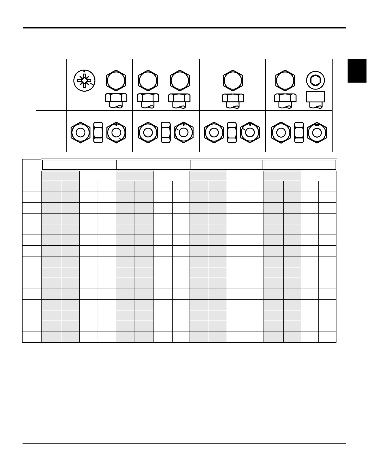
Metric Fastener Torque Values
4.8
Property
Class
and
Head
Markings
4.8
4.8
8.8
8.8
8.8
9.8
9.8
9.8
10.9
10.9
10.9
12.9
12.9
12.9
12.9
Property
Class
and
Nut
Markings
5
5
5 10
10
MIF
10
10
10
10
12
12
12
Class 4.8 Class 8.8 or 9.8 Class 10.9 Class 12.9
Lubricated a Dry a Lubricated a Dry a Lubricated a Dry a Lubricated a Dry a
SIZE N•m lb-ft N•m lb-ft N•m lb-ft N•m lb-ft N•m lb-ft N•m lb-ft N•m lb-ft N•m lb-ft
M6 4.8 3.5 6 4.5 9 6.5 11 8.5 13 9.5 17 12 15 11.5 19 14.5
M8 12 8.5 15 11 22 16 28 20 32 24 40 30 37 28 47 35
M10 23 17 29 21 43 32 55 40 63 47 80 60 75 55 95 70
M12 40 29 50 37 75 55 95 70 110 80 140 105 130 95 165 120
M14 63 47 80 60 120 88 150 110 175 130 225 165 205 150 260 109
M16 100 73 125 92 190 140 240 175 275 200 350 225 320 240 400 300
M18 135 100 175 125 260 195 330 250 375 275 475 350 440 325 560 410
M20 190 140 240 180 375 275 475 350 530 400 675 500 625 460 800 580
M22 260 190 330 250 510 375 650 475 725 540 925 675 850 625 1075 800
M24 330 250 425 310 650 475 825 600 925 675 1150 850 1075 800 1350 1000
M27 490 360 625 450 950 700 1200 875 1350 1000 1700 1250 1600 1150 2000 1500
M30 675 490 850 625 1300 950 1650 1200 1850 1350 2300 1700 2150 1600 2700 2000
M33 900 675 1150 850 1750 1300 2200 1650 2500 1850 3150 2350 2900 2150 3700 2750
M36 1150 850 1450 1075 2250 1650 2850 2100 3200 2350 4050 3000 3750 2750 4750 3500
DO NOT use these hand torque values if a different torque
value or tightening procedure is given for a specific
application. Torque values listed are for general use only
and include a ±10% variance factor. Check tightness of
fasteners periodically. DO NOT use air powered wrenches.
Shear bolts are designed to fail under predetermined loads.
Always replace shear bolts with identical grade.
Fasteners should be replaced with the same grade. Make
sure fastener threads are clean and that you properly start
thread engagement. This will prevent them from failing
when tightening.
When bolt and nut combination fasteners are used, torque
values should be applied to the NUT instead of the bolt
head.
Tighten toothed or serrated-type lock nuts to the full torque
value.
a “Lubricated” means coated with a lubricant such as
engine oil, or fasteners with phosphate and oil coatings.
“Dry” means plain or zinc plated (yellow dichromate Specification JDS117) without any lubrication.
Reference: JDS - G200.
Specifications Fastener Torques - 7
Page 12
SPECIFICATIONS FASTENER TORQUES
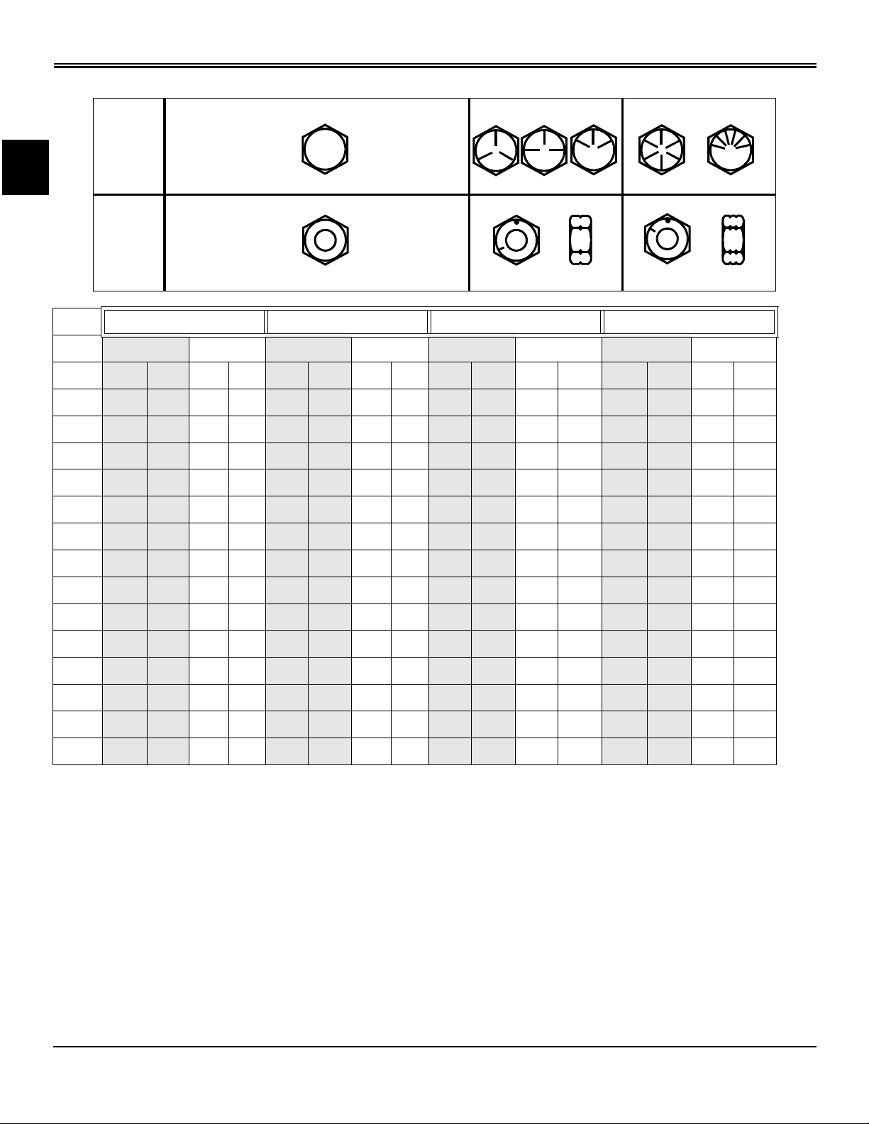
Inch Fastener Torque Values
SAE
Grade
and Head
Markings
No Marks
1 or 2
b
5
5.1
5.2
8
8.2
5
8
SAE
Grade
and Nut
Markings
2
No Marks
MIF
Grade 1 Grade 2b Grade 5, 5.1 or 5.2 Grade 8 or 8.2
Lubricated a Dry a Lubricated a Dry a Lubricated a Dry a Lubricated a Dry a
SIZE N•m lb-ft N•m lb-ft N•m lb-ft N•m lb-ft N•m lb-ft N•m lb-ft N•m lb-ft N•m lb-ft
1/4 3.7 2.8 4.7 3.5 6 4.5 7.5 5.5 9.5 7 12 9 13.5 10 17 12.5
5/16 7.7 5.5 10 7 12 9 15 11 20 15 25 18 28 21 35 26
3/8 14 10 17 13 22 16 27 20 35 26 44 33 50 36 63 46
7/16 22 16 28 20 35 26 44 32 55 41 70 52 80 58 100 75
1/2 33 25 42 31 53 39 67 50 85 63 110 80 120 90 150 115
9/16 48 36 60 45 75 56 95 70 125 90 155 115 175 130 225 160
5/8 67 50 85 62 105 78 135 100 170 125 215 160 215 160 300 225
3/4 120 87 150 110 190 140 240 175 300 225 375 280 425 310 550 400
7/8 190 140 240 175 190 140 240 175 490 360 625 450 700 500 875 650
1 290 210 360 270 290 210 360 270 725 540 925 675 1050 750 1300 975
1-1/8 470 300 510 375 470 300 510 375 900 675 1150 850 1450 1075 1850 1350
1-1/4 570 425 725 530 570 425 725 530 1300 950 1650 1200 2050 1500 2600 1950
1-3/8 750 550 950 700 750 550 950 700 1700 1250 2150 1550 2700 2000 3400 2550
1-1/2 1000 725 1250 925 990 725 1250 930 2250 1650 2850 2100 3600 2650 4550 3350
DO NOT use these hand torque values if a different torque
value or tightening procedure is given for a specific
application. Torque values listed are for general use only
and include a ±10% variance factor. Check tightness of
fasteners periodically. DO NOT use air powered wrenches.
Shear bolts are designed to fail under predetermined loads.
Always replace shear bolts with identical grade.
Fasteners should be replaced with the same grade. Make
sure fastener threads are clean and that you properly start
thread engagement. This will prevent them from failing
when tightening.
When bolt and nut combination fasteners are used, torque
values should be applied to the NUT instead of the bolt
head.
Tighten toothed or serrated-type lock nuts to the full torque
value.
a “Lubricated” means coated with a lubricant such as
engine oil, or fasteners with phosphate and oil coatings.
“Dry” means plain or zinc plated (yellow dichromate Specification JDS117) without any lubrication.
b “Grade 2” applies for hex cap screws (Not Hex Bolts) up
to 152 mm (6 in.) long. “Grade 1” applies for hex cap
screws over 152 mm (6 in.) long, and for all other types of
bolts and screws of any length.
Reference: JDS - G200
Specifications Fastener Torques - 8
Page 13
SPECIFICATIONS GENERAL INFORMATION
General Information
Gasoline
4 - Cycle Engines
c
CAUTION: Avoid Injury! Gasoline is
HIGHLY FLAMMABLE, handle it with care.
DO NOT refuel machine while: indoors,
always fill gas tank outdoors; machine is
near an open flame or sparks; engine is
running, STOP engine; engine is hot, allow
it to cool sufficiently first; smoking.
Help prevent fires: fill gas tank to bottom of
filler neck only; be sure fill cap is tight after
fueling; clean up any gas spills
IMMEDIATELY; keep machine clean and in
good repair - free of excess grease, oil,
debris, and faulty or damaged parts; any
storage of machines with gas left in tank
should be in an area that is well ventilated
to prevent possible igniting of fumes by an
open flame or spark, this includes any
appliance with a pilot light. To prevent fire
or explosion caused by STATIC ELECTRIC
DISCHARGE during fueling:•ONLY use a
clean, approved POLYETHYLENE PLASTIC
fuel container and funnel WITHOUT any
metal screen or filter.
To avoid engine damage:
• DO NOT mix oil with gasoline;
• ONLY use clean, fresh unleaded gasoline with an
octane rating (anti-knock index) of 87 or higher;
• fill gas tank at the end of each day's operation to help
prevent condensation from forming inside a partially filled
tank;
• keep up with specified service intervals.
Use of alternative oxygenated, gasohol blended, unleaded
gasoline is acceptable as long as:
MIF
IMPORTANT: Avoid damage! California
Proposition 65 Warning: Gasoline engine
exhaust from this product contains chemicals
known to the State of California to cause cancer,
birth defects, or other reproductive harm.
Gasoline Storage
IMPORTANT: Avoid damage! Keep all dirt, scale,
water or other foreign material out of gasoline.
Keep gasoline stored in a safe, protected area. Storage of
gasoline in a clean, properly marked (“UNLEADED
GASOLINE”) POLYETHYLENE PLASTIC container
WITHOUT any metal screen or filter is recommended. DO
NOT use de-icers to attempt to remove water from gasoline
or depend on fuel filters to remove water from gasoline.
Use a water separator installed in the storage tank outlet.
BE SURE to properly discard unstable or contaminated
gasoline. When storing the machine or gasoline, it is
recommended that you add John Deere Gasoline
Conditioner and Stabilizer (TY15977) or an equivalent to
the gasoline. BE SURE to follow directions on container
and to properly discard empty container.
• the ethyl or grain alcohol blends DO NOT exceed 10%
by volume or
• methyl tertiary butyl ether (MTBE) blends DO NOT
exceed 15% by volume
RFG (reformulated) gasoline is acceptable for all machines
designed for use of regular unleaded fuel. Older machines
(that were designed for leaded fuel) may see some
accelerated valve and seat wear.
Specifications General Information - 9
Page 14
SPECIFICATIONS GENERAL INFORMATION
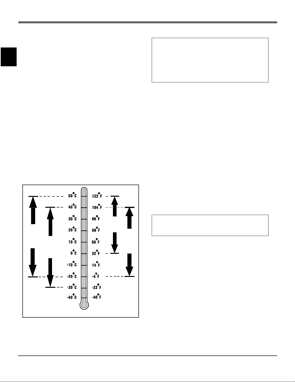
4 - Cycle Gasoline Engine Oil
Use the appropriate oil viscosity based on the expected air
temperature range during the period between
recommended oil changes. Operating outside of these
recommended oil air temperature ranges may cause
premature engine failure.
The following John Deere oils are PREFERRED:
• PLUS - 4® - SAE 10W-40;
• TORQ - GARD SUPREME® - SAE 5W-30.
The following John Deere oils are also recommended,
based on their specified temperature range:
• TURF - GARD® - SAE 10W-30;
• PLUS - 4® - SAE 10W-30;
• TORQ - GARD SUPREME® - SAE 30.
Other oils may be used if above John Deere oils are not
available, provided they meet one of the following
specifications:
• SAE 10W-40 - API Service Classifications SG or higher;
• SAE 5W-30 - API Service Classification SG or higher;
• SAE 10W-30 - API Service Classifications SG or higher;
• SAE 30 - API Service Classification SC or higher.
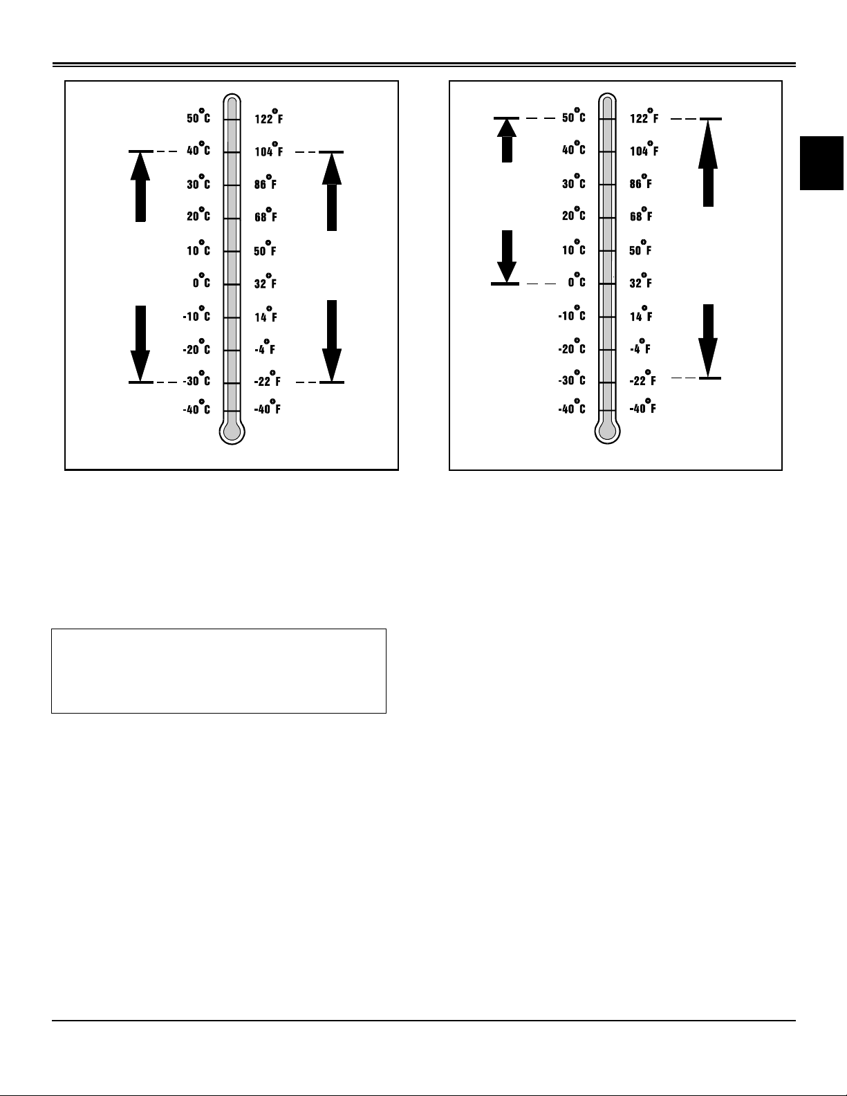
Break-In Engine Oil - 4-Cycle Gasoline
IMPORTANT: Avoid damage! ONLY use a quality
break-in oil in rebuilt or remanufactured engines
for the first 5 hours (maximum) of operation. DO
NOT use oils with heavier viscosity weights than
SAE 5W-30 or oils meeting specifications API SG
or SH, these oils will not allow rebuilt or
remanufactured engines to break-in properly.
The following John Deere oil is PREFERRED:
• BREAK - IN ENGINE OIL.
John Deere BREAK - IN ENGINE OIL is formulated with
special additives for aluminum and cast iron type engines
to allow the power cylinder components (pistons, rings, and
liners as well) to “wear-in” while protecting other engine
components, valve train and gears, from abnormal wear.
Engine rebuild instructions should be followed closely to
determine if special requirements are necessary.
John Deere BREAK - IN ENGINE OIL is also
recommended for non-John Deere engines, both aluminum
and cast iron types.
The following John Deere oil is also recommended:
• TORQ - GARD SUPREME® - SAE 5W-30.
If the above recommended John Deere oils are not
available, use a break-in engine oil meeting the following
specification during the first 5 hours (maximum) of
operation:
• SAE 5W-30 - API Service Classification SE or higher.
SAE 10W-40
SAE 5W-30
PREFERRED
AIR TEMPERATURE
SAE 30
IMPORTANT: Avoid damage! After the break-in
period, use the John Deere oil that is
recommended for this engine.
SAE 10W-30
MIF
Specifications General Information - 10
Page 15
SPECIFICATIONS GENERAL INFORMATION
JDM J20C
BREAK-IN OIL
SAE 5W-30
PREFERRED
AIR TEMPERATURE
MIF
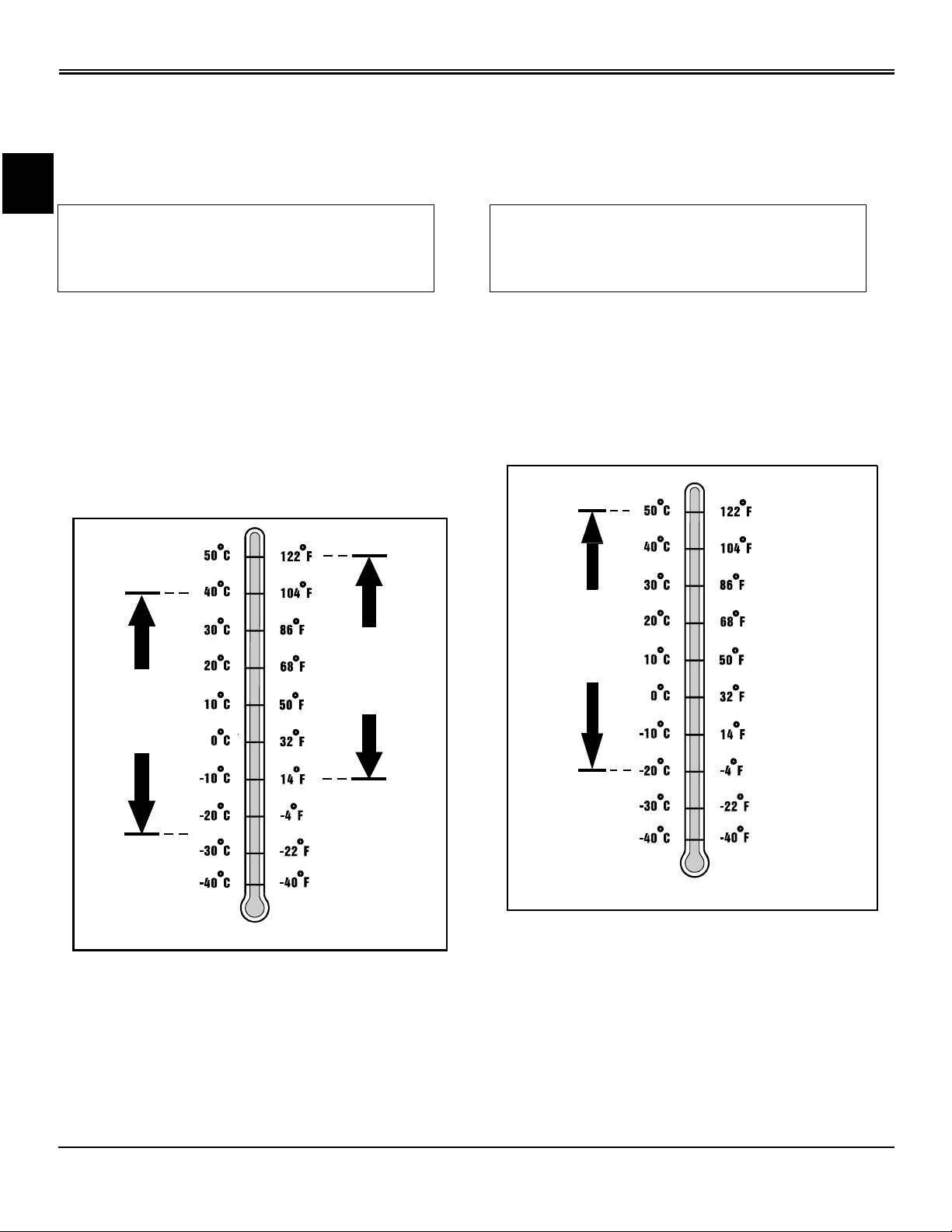
Hydrostatic Transmission and Hydraulic Oil
Use the appropriate oil viscosity based on these air
temperature ranges. Operating outside of these
recommended oil air temperature ranges may cause
premature hydrostatic transmission or hydraulic system
failures.
IMPORTANT: Avoid damage! Use only the oils
recommended. HY-GARD® - JDM J20C can be
mixed with 5W30 or 10W30 in this application.
Do not use LOW VISCOSITY HY - GARD® oil.
5W30 or 10W30
PREFERRED
AIR TEMPERATURE
MIF
The following John Deere transmission and hydraulic oil is
PREFERRED:
• HY-GARD® - JDM J20C.
The following John Deere oil is also recommended if above
preferred oil is not available:
• 5W30 or 10W30.
Other oils may be used if above recommended John Deere
oils are not available, provided they meet one of the
following specifications:
• John Deere Standard JDM J20C.
Specifications General Information - 11
Page 16
SPECIFICATIONS GENERAL INFORMATION
Gear Case Oil
Use the appropriate oil viscosity based on the air
temperature ranges. Operating outside of these
recommended oil air temperature ranges may cause
premature gear case failure.
IMPORTANT: Avoid damage! ONLY use a quality
oil in this gear case. DO NOT mix any other oils
in this gear case. DO NOT use BIO-HY-GARD® in
this gear case.
The following John Deere gear case oil is PREFERRED:
• GL-5 GEAR LUBRICANT® - SAE 80W-90.
The following John Deere gear case oil is also
recommended if above preferred oil is not available:
• GL-5 GEAR LUBRICANT® - SAE 85W-140.
Other gear case oils may be used if above recommended
John Deere gear case oils are not available, provided they
meet the following specification:
• API Service Classification GL - 5.
Gear Transmission Grease
Use the following gear grease based on the air temperature
range. Operating outside of the recommended grease air
temperature range may cause premature gear
transmission failure.
IMPORTANT: Avoid damage! ONLY use a quality
gear grease in this transmission. DO NOT mix
any other greases in this transmission. DO NOT
use any BIO - GREASE in this transmission.
The following John Deere gear grease is PREFERRED:
• NON-CLAY HIGH-TEMPERATURE EP GREASE® -
JDM J13E4, NLGI Grade 2.
Other greases may be used if above preferred John Deere
grease is not available, provided they meet the following
specification:
• John Deere Standard JDM J13E4, NLGI Grade 2.
SAE 80W-90
PREFERRED
AIR TEMPERATURE
SAE 85W-140
MIF
JDM J13E4
NLGI Grade 2
AIR TEMPERATURE
MIF
Alternative Lubricants
Use of alternative lubricants could cause reduced life of the
component.
If alternative lubricants are to be used, it is recommended
that the factory fill be thoroughly removed before switching
to any alternative lubricant.
Specifications General Information - 12
Page 17

SPECIFICATIONS COOLANT SPECIFICATIONS
Synthetic Lubricants
Synthetic lubricants may be used in John Deere equipment
if they meet the applicable performance requirements
(industry classification and/or military specification) as
shown in this manual.
The recommended air temperature limits and service or
lubricant change intervals should be maintained as shown
in the operator’s manual, unless otherwise stated on
lubricant label.
Avoid mixing different brands, grades, or types of oil. Oil
manufacturers blend additives in their oils to meet certain
specifications and performance requirements. Mixing
different oils can interfere with the proper functioning of
these additives and degrade lubricant performance.
Lubricant Storage
All machines operate at top efficiency only when clean
lubricants are used. Use clean storage containers to
handle all lubricants. Store them in an area protected from
dust, moisture, and other contamination. Store drums on
their sides. Make sure all containers are properly marked
as to their contents. Dispose of all old, used containers and
their contents properly.
Coolant Specifications
Gasoline Engine Coolant
The engine cooling system when filled with a proper
dilution mixture of anti-freeze and deionized or distilled
water provides year-round protection against corrosion,
cylinder or liner pitting, and winter freeze protection down
to -37°C (-34°F).
The following John Deere coolant is PREFERRED:
• COOL-GARD® PRE-DILUTED SUMMER COOLANT
(TY16036).
This coolant satisfies specifications for “Automobile and
Light Duty Engine Service” and is safe for use in John
Deere Lawn and Grounds Care/Golf and Turf Division
equipment, including aluminum block gasoline engines and
cooling systems.
The above preferred pre-diluted anti-freeze provides:
• adequate heat transfer
• corrosion-resistant chemicals for the cooling system
• compatibility with cooling system hose and seal material
• protection during extreme cold and extreme hot weather
operations
Mixing of Lubricants
In general, avoid mixing different brands or types of
lubricants. Manufacturers blend additives in their lubricants
to meet certain specifications and performance
requirements. Mixing different lubricants can interfere with
the proper functioning of these additives and lubricant
properties which will downgrade their intended specified
performance.
Oil Filters
IMPORTANT: Avoid damage! Filtration of oils is
critical to proper lubrication performance.
Always change filters regularly.
The following John Deere oil filters are PREFERRED:
• AUTOMOTIVE AND LIGHT TRUCK ENGINE OIL
FILTERS.
Most John Deere filters contain pressure relief and antidrainback valves for better engine protection.
Other oil filters may be used if above recommended John
Deere oil filters are not available, provided they meet the
following specification:
• ASTB Tested In Accordance With SAE J806.
• chemically pure water for better service life
• compliance with ASTM D4656 (JDM H24C2)
specifications
If above preferred pre-diluted coolant is not available, the
following John Deere concentrate is recommended:
• COOL-GARD® CONCENTRATED SUMMER
COOLANT CONCENTRATE™ (TY16034).
If either of above recommended engine coolants are
available use any Automobile and Light Duty Engine
Service ethylene glycol base coolant, meeting the following
specification:
• ASTM D4985 (JDM H24A2).
Read container label completely before using and follow
instructions as stated.
Specifications Coolant Specifications - 13
Page 18
SPECIFICATIONS COOLANT SPECIFICATIONS
IMPORTANT: Avoid damage! To prevent engine
damage, DO NOT use pure anti-freeze or less
than a 50% anti-freeze mixture in the cooling
system. DO NOT mix or add any additives/
conditioners to the cooling system in Lawn and
Grounds Care/Golf and Turf Division equipment.
Water used to dilute engine coolant concentrate
must be of high quality - clean, clear, potable
water (low in chloride and hardness - Table 1) is
generally acceptable. DO NOT use salt water.
Deionized or distilled water is ideal to use.
Coolant that is not mixed to these specified
levels and water purity can cause excessive
scale, sludge deposits, and increased corrosion
potential.
Property Requirements
Total Solids, Maximum 340 ppm (20 grns/gal)
Total Hardness, Maximum 170 ppm (10 grns/gal)
Chloride (as Cl), Maximum 40 ppm (2.5 grns/gal)
Sulfate (as SO4), Maximum 100 ppm (5.8 grns/gal)
Mix 50 percent anti-freeze concentrate with 50 percent
distilled or deionized water. This mixture and the pre-diluted
mixture (TY16036) will protect the cooling system down to 37°C (-34°F) and up to 108°C (226°F).
Certain geographical areas may require lower air
temperature protection. See the label on your anti-freeze
container or consult your John Deere dealer to obtain the
latest information and recommendations.
Gasoline Engine Coolant Drain Interval
When using John Deere Pre-Diluted (TY16036) Automobile
and Light Duty Engine Service coolants, drain and flush the
cooling system and refill with fresh coolant mixture every
36 months or 3,000 hours of operation, whichever comes
first.
When using John Deere Concentrate (TY16034)
Automobile and Light Duty Engine Service coolants, drain
and flush the cooling system and refill with fresh coolant
mixture every 24 months or 2,000 hours of operation,
whichever comes first.
If above John Deere Automobile and Light Duty Engine
Service coolants are not being used; drain, flush, and refill
the cooling system according to instructions found on
product container or in equipment operator’s manual or
technical manual.
Specifications Coolant Specifications - 14
Page 19

SPECIFICATIONS SPECIFICATIONS - TRAIL BUCK
Specifications - Trail Buck
Engine Specifications - 500
Stroke (500 cc Engine) . . . . . . . . . . . . . . . . . . . . . . . . . . . . . . . . . . . . . . . . . . . . . . . . . . . . . . . . . . . . . . . . 63 mm (2.5 in.)
Displacement (500 cc Engine). . . . . . . . . . . . . . . . . . . . . . . . . . . . . . . . . . . . . . . . . . . . . . . . . . . . . . . 498 cc (30.4 cu in.)
Horsepower @ 7200 rpm (500 cc Engine) . . . . . . . . . . . . . . . . . . . . . . . . . . . . . . . . . . . . . . . . . . . . . . . . 27.6 kW (37 hp)
Engine Specifications - 650
Stroke (650 cc Engine) . . . . . . . . . . . . . . . . . . . . . . . . . . . . . . . . . . . . . . . . . . . . . . . . . . . . . . . . . . . . . . . . 82 mm (3.2 in.)
Displacement (650 cc Engine). . . . . . . . . . . . . . . . . . . . . . . . . . . . . . . . . . . . . . . . . . . . . . . . . . . . . . . 644 cc (39.3 cu in.)
Horsepower @ 7100 rpm (650 cc Engine) . . . . . . . . . . . . . . . . . . . . . . . . . . . . . . . . . . . . . . . . . . . . . . . . 31.3 kW (42 hp)
Engine Specifications - 500 and 650
General Specifications
Make. . . . . . . . . . . . . . . . . . . . . . . . . . . . . . . . . . . . . Rotax 4-TEC, 4 stroke Over Head Camshaft (OHC), Liquid cooled
Starting System . . . . . . . . . . . . . . . . . . . . . . . . . . . . . . . . . . . . . . . . . . . . . . . . . . . . . . . . . . Electric with Optional Recoil
Number of Cylinder(s) . . . . . . . . . . . . . . . . . . . . . . . . . . . . . . . . . . . . . . . . . . . . . . . . . . . . . . . . . . . . . . . . . . . . . . . . . . . . 1
Number of Valves . . . . . . . . . . . . . . . . . . . . . . . . . . . . . . . . . . . . . . . . . . . . . . . . . . . . . . . . . . . . . . . . . . . . . . . . . . 4 valves
Decompressor Type . . . . . . . . . . . . . . . . . . . . . . . . . . . . . . . . . . . . . . . . . . . . . . . . . . . . . . . . . . . . . . . . . . . . . . .Automatic
Bore (Standard). . . . . . . . . . . . . . . . . . . . . . . . . . . . . . . . . . . . . . . . . . . . . . . . . . . . . . . . . . . . . . . . . . . . . 100 mm (3.9 in.)
Compression Ratio. . . . . . . . . . . . . . . . . . . . . . . . . . . . . . . . . . . . . . . . . . . . . . . . . . . . . . . . . . . . . . . . . . . . . . . . . . . . 9.5:1
Maximum HP RPM . . . . . . . . . . . . . . . . . . . . . . . . . . . . . . . . . . . . . . . . . . . . . . . . . . . . . . . . . . . . . . . . . . . .7000 ± 100 rpm
Lubrication . . . . . . . . Wet sump with replaceable oil filter (lubrication of engine and transmission simultaneously)
Oil Filter. . . . . . . . . . . . . . . . . . . . . . . . . . . . . . . . . . . . . . . . . . . . . . . . . . . . . . . . . . . . . . . . . . . . . . . . . . . . . . . . . . Full flow
Air Filter Type . . . . . . . . . . . . . . . . . . . . . . . . . . . . . . . . . . . . . . . . . . . . . . . . . . . . . . . . . . . . . . . . . . . . . 2 stage foam filter
Exhaust System Type. . . . . . . . . . . . . . . . . . . . . . . . . . . . . . . . . . . . . . . . . . . . . . . . . . . . . . . . . . . Nelson, stainless steel
Exhaust System Spark Arrester . . . . . . . . . . . . . . . . . . . . . . . . . . . . . . . . . . . . . . . . . . . . . . . . . . . . . . . .USDA approved
Valves
Intake Valve Opening . . . . . . . . . . . . . . . . . . . . . . . . . . . . . . . . . . . . . . . . . . . . . . . . . . . . . . . . . . . . . . . . . . . . .10.0° BTDC
Intake Valve Closing. . . . . . . . . . . . . . . . . . . . . . . . . . . . . . . . . . . . . . . . . . . . . . . . . . . . . . . . . . . . . . . . . . . . . 55.0° ABDC
Exhaust Valve Opening . . . . . . . . . . . . . . . . . . . . . . . . . . . . . . . . . . . . . . . . . . . . . . . . . . . . . . . . . . . . . . . . . . 50.0° BBDC
Exhaust Valve Closing . . . . . . . . . . . . . . . . . . . . . . . . . . . . . . . . . . . . . . . . . . . . . . . . . . . . . . . . . . . . . . . . . . . . . 5.0° ATDC
Intake Valve Stem Diameter (New minimum) . . . . . . . . . . . . . . . . . . . . . . . . . . . . . . . . . . . . . . . . . 5.961 mm (0.2347 in.)
Intake Valve Stem Diameter (New maximum) . . . . . . . . . . . . . . . . . . . . . . . . . . . . . . . . . . . . . . . . 5.975 mm (0.2352 in.)
Intake Valve Stem Diameter (Wear limit) . . . . . . . . . . . . . . . . . . . . . . . . . . . . . . . . . . . . . . . . . . . . 5.930 mm (0.2330 in.)
Exhaust Valve Stem Diameter (New minimum) . . . . . . . . . . . . . . . . . . . . . . . . . . . . . . . . . . . . . . . 5.946 mm (0.2341 in.)
Exhaust Valve Stem Diameter (New maximum). . . . . . . . . . . . . . . . . . . . . . . . . . . . . . . . . . . . . . . 5.960 mm (0.2346 in.)
Exhaust Valve Stem Diameter (Wear limit). . . . . . . . . . . . . . . . . . . . . . . . . . . . . . . . . . . . . . . . . . . 5.930 mm (0.2330 in.)
Valve Guide Diameter (Wear limit) . . . . . . . . . . . . . . . . . . . . . . . . . . . . . . . . . . . . . . . . . . . . . . . . . 6.060 mm (0.2386 in.)
Valve Spring Free Length (New) . . . . . . . . . . . . . . . . . . . . . . . . . . . . . . . . . . . . . . . . . . . . . . . . . . . . 45.45 mm (1.789 in.)
Valve Spring Free Length (Wear limit) . . . . . . . . . . . . . . . . . . . . . . . . . . . . . . . . . . . . . . . . . . . . . . . 43.00 mm (1.693 in.)
Intake Valve Seat Contact Width (New). . . . . . . . . . . . . . . . . . . . . . . . . . . . . . . . . . 1.10 to 1.30 mm (0.043 to 0.0051 in.)
Intake Valve Seat Contact Width (Wear limit). . . . . . . . . . . . . . . . . . . . . . . . . . . . . . . . . . . . . . . . . . . . . 1.8 mm (0.07 in.)
Exhaust Valve Seat Contact Width (New). . . . . . . . . . . . . . . . . . . . . . . . . . . . . . . . . 1.25 to 1.55 mm (0.049 to 0.061 in.)
Exhaust Valve Seat Contact Width (Wear limit) . . . . . . . . . . . . . . . . . . . . . . . . . . . . . . . . . . . . . . . . . . 2.0 mm (0.078 in.)
Specifications Specifications - Trail Buck - 15
Page 20

SPECIFICATIONS SPECIFICATIONS - TRAIL BUCK
Pistons
Piston Measurement (New) . . . . . . . . . . . . . . . . . . . . . . . . . . . . . . . . . . . . . . . . 99.951 to 99.969 mm (3.935 to 3.936 in.)
Piston Measurement (Wear limit) . . . . . . . . . . . . . . . . . . . . . . . . . . . . . . . . . . . . . . . . . . . . . . . . . . . 99.80 mm (3.929 in.)
Piston/Cylinder Clearance (New) . . . . . . . . . . . . . . . . . . . . . . . . . . . . . . . . . . . . . 0.031 to 0.059 mm (0.001 to 0.002 in.)
Piston/Cylinder Clearance (Wear limit) . . . . . . . . . . . . . . . . . . . . . . . . . . . . . . . . . . . . . . . . . . . . . . 0.090 mm (0.004 in.)
Piston Ring Type 1st . . . . . . . . . . . . . . . . . . . . . . . . . . . . . . . . . . . . . . . . . . . . . . . . . . . . . . . . . . . . . . . . . . . . Rectangular
Piston Ring Type 2nd . . . . . . . . . . . . . . . . . . . . . . . . . . . . . . . . . . . . . . . . . . . . . . . . . . . . . . . . . . . . . . . . . . . . . Taper-face
Piston Ring Type 3rd . . . . . . . . . . . . . . . . . . . . . . . . . . . . . . . . . . . . . . . . . . . . . . . . . . . . . . . . . . . . . . . . Oil Scraper Ring
Piston Ring End Gap Rectangular (New minimum) . . . . . . . . . . . . . . . . . . . . . . . . . . . . . . . . . . . . . 0.15 mm (0.006 in.)
Piston Ring End Gap Taper-face (New minimum) . . . . . . . . . . . . . . . . . . . . . . . . . . . . . . . . . . . . . . . 0.15 mm (0.006 in.)
Piston Ring End Gap Oil Scraper Ring (New minimum). . . . . . . . . . . . . . . . . . . . . . . . . . . . . . . . . . 0.15 mm (0.006 in.)
Piston Ring End Gap Rectangular (New maximum) . . . . . . . . . . . . . . . . . . . . . . . . . . . . . . . . . . . . . 0.35 mm (0.014 in.)
Piston Ring End Gap Taper-face (New maximum) . . . . . . . . . . . . . . . . . . . . . . . . . . . . . . . . . . . . . . 0.35 mm (0.014 in.)
Piston Ring End Gap Oil Scraper Ring (New maximum) . . . . . . . . . . . . . . . . . . . . . . . . . . . . . . . . . 0.30 mm (0.012 in.)
Piston Ring End Gap All (Wear limit) . . . . . . . . . . . . . . . . . . . . . . . . . . . . . . . . . . . . . . . . . . . . . . . . . . . 1.5 mm (0.06 in.)
Piston/Ring Groove Clearance Rectangular (New minimum) . . . . . . . . . . . . . . . . . . . . . . . . . . . . 0.025 mm (0.001 in.)
Piston/Ring Groove Clearance Taper-face (New minimum) . . . . . . . . . . . . . . . . . . . . . . . . . . . . . 0.015 mm (0.0006 in.)
Piston/Ring Groove Clearance Oil Scraper Ring (New minimum). . . . . . . . . . . . . . . . . . . . . . . . 0.020 mm (0.0008 in.)
Piston/Ring Groove Clearance Rectangular (New maximum) . . . . . . . . . . . . . . . . . . . . . . . . . . . 0.070 mm (0.0028 in.)
Piston/Ring Groove Clearance Taper-face (New maximum) . . . . . . . . . . . . . . . . . . . . . . . . . . . . 0.060 mm (0.0024 in.)
Piston/Ring Groove Clearance Oil Scraper Ring (New maximum) . . . . . . . . . . . . . . . . . . . . . . . 0.055 mm (0.0021 in.)
Rocker Arm
Rocker Arm Bore Diameter (New minimum) . . . . . . . . . . . . . . . . . . . . . . . . . . . . . . . . . . . . . . . . 20.007 mm (0.7877 in.)
Rocker Arm Bore Diameter (New maximum) . . . . . . . . . . . . . . . . . . . . . . . . . . . . . . . . . . . . . . . . 20.020 mm (0.7881 in.)
Rocker Arm Bore Diameter (Wear limit) . . . . . . . . . . . . . . . . . . . . . . . . . . . . . . . . . . . . . . . . . . . . 20.035 mm (0.7887 in.)
Rocker Arm Shaft Diameter (New minimum) . . . . . . . . . . . . . . . . . . . . . . . . . . . . . . . . . . . . . . . . 19.980 mm (0.7866 in.)
Rocker Arm Shaft Diameter (New maximum) . . . . . . . . . . . . . . . . . . . . . . . . . . . . . . . . . . . . . . . 20.007 mm (0.7877 in.)
Rocker Arm Shaft Diameter (Wear limit) . . . . . . . . . . . . . . . . . . . . . . . . . . . . . . . . . . . . . . . . . . . 19.965 mm (0.7860 in.)
Cylinder
Cylinder Screw M11 (Service limit) . . . . . . . . . . . . . . . . . . . . . . . . . . . . . . . . . . . . . . . . . . . . . . . . . . 216.5 mm (8.524 in.)
Cylinder Bore (New) . . . . . . . . . . . . . . . . . . . . . . . . . . . . . . . . . . . . . . . . . . . . . . . . . . . . . . . . . . . . . . 100.00 mm (3.94 in.)
Cylinder Taper (New maximum) . . . . . . . . . . . . . . . . . . . . . . . . . . . . . . . . . . . . . . . . . . . . . . . . . . . 0.038 mm (0.0015 in.)
Cylinder Taper (Wear limit) . . . . . . . . . . . . . . . . . . . . . . . . . . . . . . . . . . . . . . . . . . . . . . . . . . . . . . . . 0.090 mm (0.004 in.)
Cylinder Out of Round (New maximum). . . . . . . . . . . . . . . . . . . . . . . . . . . . . . . . . . . . . . . . . . . . . . 0.01 mm (0.0004 in.)
Cylinder Out of Round (Wear limit). . . . . . . . . . . . . . . . . . . . . . . . . . . . . . . . . . . . . . . . . . . . . . . . . . 0.02 mm (0.0008 in.)
Camshaft and Cam
Camshaft Bearing Journal PTO Side (New minimum) . . . . . . . . . . . . . . . . . . . . . . . . . . . . . . . . 24.967 mm (0.9829 in.)
Camshaft Bearing Journal PTO Side (New maximum) . . . . . . . . . . . . . . . . . . . . . . . . . . . . . . . . 24.980 mm (0.9835 in.)
Camshaft Bearing Journal PTO Side (Wear limit) . . . . . . . . . . . . . . . . . . . . . . . . . . . . . . . . . . . . 24.960 mm (0.9827 in.)
Camshaft Bearing Journal Magneto Side (New minimum). . . . . . . . . . . . . . . . . . . . . . . . . . . . . 39.927 mm (1.5719 in.)
Camshaft Bearing Journal Magneto Side (New maximum) . . . . . . . . . . . . . . . . . . . . . . . . . . . . 39.935 mm (1.5722 in.)
Camshaft Bearing Journal Magneto Side (Wear limit) . . . . . . . . . . . . . . . . . . . . . . . . . . . . . . . . 39.920 mm (1.5716 in.)
Camshaft Bore PTO Side (New minimum) . . . . . . . . . . . . . . . . . . . . . . . . . . . . . . . . . . . . . . . . . . 24.987 mm (0.9837 in.)
Camshaft Bore PTO Side (New maximum). . . . . . . . . . . . . . . . . . . . . . . . . . . . . . . . . . . . . . . . . . 25.000 mm (0.9842 in.)
Camshaft Bore PTO Side (Wear limit). . . . . . . . . . . . . . . . . . . . . . . . . . . . . . . . . . . . . . . . . . . . . . 25.020 mm (0.9850 in.)
Specifications Specifications - Trail Buck - 16
Page 21

SPECIFICATIONS SPECIFICATIONS - TRAIL BUCK
Camshaft Bore Magneto Side (New minimum) . . . . . . . . . . . . . . . . . . . . . . . . . . . . . . . . . . . . . . 39.984 mm (1.5742 in.)
Camshaft Bore Magneto Side (New maximum) . . . . . . . . . . . . . . . . . . . . . . . . . . . . . . . . . . . . . . 40.000 mm (1.5748 in.)
Camshaft Bore Magneto Side (Wear limit) . . . . . . . . . . . . . . . . . . . . . . . . . . . . . . . . . . . . . . . . . . 40.020 mm (1.5756 in.)
Cam Lobe Intake (New minimum) . . . . . . . . . . . . . . . . . . . . . . . . . . . . . . . . . . . . . . . . . . . . . . . . . . 31.369 mm (1.235 in.)
Cam Lobe Intake (New maximum) . . . . . . . . . . . . . . . . . . . . . . . . . . . . . . . . . . . . . . . . . . . . . . . . . 31.569 mm (1.243 in.)
Cam Lobe Intake (Wear limit) . . . . . . . . . . . . . . . . . . . . . . . . . . . . . . . . . . . . . . . . . . . . . . . . . . . . . 31.300 mm (1.232 in.)
Cam Lobe Exhaust (New minimum) . . . . . . . . . . . . . . . . . . . . . . . . . . . . . . . . . . . . . . . . . . . . . . . . 31.147 mm (1.226 in.)
Cam Lobe Exhaust (New maximum). . . . . . . . . . . . . . . . . . . . . . . . . . . . . . . . . . . . . . . . . . . . . . . . 31.347 mm (1.234 in.)
Cam Lobe Exhaust (Wear limit). . . . . . . . . . . . . . . . . . . . . . . . . . . . . . . . . . . . . . . . . . . . . . . . . . . . 31.100 mm (1.224 in.)
Crankshaft
Crankshaft Axial Clearance (New minimum) . . . . . . . . . . . . . . . . . . . . . . . . . . . . . . . . . . . . . . . . . . . 0.2 mm (0.0078 in.)
Crankshaft Axial Clearance (New maximum) . . . . . . . . . . . . . . . . . . . . . . . . . . . . . . . . . . . . . . . . . . 0.5 mm (0.0196 in.)
Crankshaft Pin Diameter (New minimum) . . . . . . . . . . . . . . . . . . . . . . . . . . . . . . . . . . . . . . . . . . 45.017 mm (1.7723 in.)
Crankshaft Pin Diameter (New maximum) . . . . . . . . . . . . . . . . . . . . . . . . . . . . . . . . . . . . . . . . . . 45.033 mm (1.7729 in.)
Crankshaft Pin Diameter (Wear limit) . . . . . . . . . . . . . . . . . . . . . . . . . . . . . . . . . . . . . . . . . . . . . . 44.990 mm (1.7710 in.)
Crankshaft Journal Diameter MAG Side (New minimum). . . . . . . . . . . . . . . . . . . . . . . . . . . . . . 54.976 mm (2.1644 in.)
Crankshaft Journal Diameter MAG Side (New maximum) . . . . . . . . . . . . . . . . . . . . . . . . . . . . . 54.995 mm (2.1651 in.)
Crankshaft Journal Diameter MAG Side (Wear limit) . . . . . . . . . . . . . . . . . . . . . . . . . . . . . . . . . 54.950 mm (2.1634 in.)
Crankshaft Journal Diameter PTO Side (New minimum) . . . . . . . . . . . . . . . . . . . . . . . . . . . . . . 45.974 mm (1.8099 in.)
Crankshaft Journal Diameter PTO Side (New maximum) . . . . . . . . . . . . . . . . . . . . . . . . . . . . . . 45.990 mm (1.8102 in.)
Crankshaft Journal Diameter PTO Side (Wear limit) . . . . . . . . . . . . . . . . . . . . . . . . . . . . . . . . . . 45.940 mm (1.8086 in.)
Crankshaft Radial Clearance MAG Side (Service limit) . . . . . . . . . . . . . . . . . . . . . . . . . . . . . . . . . 0.07 mm (0.0028 in.)
Crankshaft Radial Clearance PTO Side (Service limit) . . . . . . . . . . . . . . . . . . . . . . . . . . . . . . . . . . 0.07 mm (0.0028 in.)
Connecting Rod
Connecting Rod Big End Diameter (Service limit) . . . . . . . . . . . . . . . . . . . . . . . . . . . . . . . . . . . . 45.080 mm (1.774 in.)
Connecting Rod Big End Clearance (Service limit) . . . . . . . . . . . . . . . . . . . . . . . . . . . . . . . . . . . . 0.09 mm (0.0035 in.)
Connecting Rod Big End Axial Play (New minimum) . . . . . . . . . . . . . . . . . . . . . . . . . . . . . . . . . . . . 0.150 mm (0.06 in.)
Connecting Rod Big End Axial Play (New maximum). . . . . . . . . . . . . . . . . . . . . . . . . . . . . . . . . . . . 0.302 mm (0.01 in.)
Connecting Rod Big End Axial Play (Wear limit). . . . . . . . . . . . . . . . . . . . . . . . . . . . . . . . . . . . . . . . . . 0.5 mm (0.02 in.)
Connecting Rod Small End Diameter (New minimum) . . . . . . . . . . . . . . . . . . . . . . . . . . . . . . . . . 23.01 mm (0.9059 in.)
Connecting Rod Small End Diameter (New maximum) . . . . . . . . . . . . . . . . . . . . . . . . . . . . . . . . 23.02 mm (0.9063 in.)
Connecting Rod Small End Diameter (Wear limit) . . . . . . . . . . . . . . . . . . . . . . . . . . . . . . . . . . . . 23.07 mm (0.9080 in.)
Piston Pin
Piston Pin Diameter (New minimum) . . . . . . . . . . . . . . . . . . . . . . . . . . . . . . . . . . . . . . . . . . . . . . 22.996 mm (0.9053 in.)
Piston Pin Diameter (New maximum) . . . . . . . . . . . . . . . . . . . . . . . . . . . . . . . . . . . . . . . . . . . . . . 23.000 mm (0.9055 in.)
Piston Pin Diameter (Wear limit) . . . . . . . . . . . . . . . . . . . . . . . . . . . . . . . . . . . . . . . . . . . . . . . . . . 22.990 mm (0.9051 in.)
Piston Pin Bore Clearance (Wear limit) . . . . . . . . . . . . . . . . . . . . . . . . . . . . . . . . . . . . . . . . . . . . . 0.080 mm (0.0035 in.)
Drive Belt (New nominal) . . . . . . . . . . . . . . . . . . . . . . . . . . . . . . . . . . . . . . . . . . . . . . . . . . . . . . . . . . 32.00 mm (1.260 in.)
Drive Belt (Service limit) . . . . . . . . . . . . . . . . . . . . . . . . . . . . . . . . . . . . . . . . . . . . . . . . . . . . . . . . . . 30.00 mm (1.181 in.)
Governor Cup Roller Diameter (New minimum) . . . . . . . . . . . . . . . . . . . . . . . . . . . . . . . . . . . . . . . 13.70 mm (0.539 in.)
Governor Cup Roller Diameter (New maximum) . . . . . . . . . . . . . . . . . . . . . . . . . . . . . . . . . . . . . . . 13.90 mm (0.547 in.)
Governor Cup Roller Diameter (New minimum) . . . . . . . . . . . . . . . . . . . . . . . . . . . . . . . . . . . . . . . 13.20 mm (0.519 in.)
Centrifugal Lever
Centrifugal Lever Pivot Bolt Diameter (New minimum) . . . . . . . . . . . . . . . . . . . . . . . . . . . . . . . . . 6.078 mm (0.239 in.)
Specifications Specifications - Trail Buck - 17
Page 22

SPECIFICATIONS SPECIFICATIONS - TRAIL BUCK
Centrifugal Lever Pivot Bolt Diameter (New maximum) . . . . . . . . . . . . . . . . . . . . . . . . . . . . . . . . . 6.100 mm (0.240 in.)
Centrifugal Lever Pivot Bolt Diameter (Service limit) . . . . . . . . . . . . . . . . . . . . . . . . . . . . . . . . . . . 6.000 mm (0.236 in.)
Centrifugal Lever Bore Diameter (Service limit) . . . . . . . . . . . . . . . . . . . . . . . . . . . . . . . . . . . . . . . 6.200 mm (0.244 in.)
Centrifugal Lever Pivot Bolt Bore Diameter (New minimum). . . . . . . . . . . . . . . . . . . . . . . . . . . . . 6.113 mm (0.241 in.)
Centrifugal Lever Pivot Bolt Bore Diameter (New maximum) . . . . . . . . . . . . . . . . . . . . . . . . . . . . 6.171 mm (0.243 in.)
Centrifugal Lever Pivot Bolt Bore Diameter (Service limit) . . . . . . . . . . . . . . . . . . . . . . . . . . . . . . 6.300 mm (0.248 in.)
Drive Pulleys
Drive Pulley Sliding Half Large Bushing (New minimum) . . . . . . . . . . . . . . . . . . . . . . . . . . . . . . 55.000 mm (2.165 in.)
Drive Pulley Sliding Half Large Bushing (New maximum) . . . . . . . . . . . . . . . . . . . . . . . . . . . . . . 55.002 mm (2.166 in.)
Drive Pulley Sliding Half Large Bushing (Service limit) . . . . . . . . . . . . . . . . . . . . . . . . . . . . . . . . 55.200 mm (2.173 in.)
Drive Pulley Sliding Half Small Bushing (New minimum) . . . . . . . . . . . . . . . . . . . . . . . . . . . . . . 30.000 mm (1.181 in.)
Drive Pulley Sliding Half Small Bushing (New maximum) . . . . . . . . . . . . . . . . . . . . . . . . . . . . . . 30.002 mm (1.182 in.)
Drive Pulley Sliding Half Small Bushing (Service limit) . . . . . . . . . . . . . . . . . . . . . . . . . . . . . . . . 30.200 mm (1.189 in.)
One-Way Clutch Bushing Diameter (New minimum) . . . . . . . . . . . . . . . . . . . . . . . . . . . . . . . . . . 39.990 mm (1.574 in.)
One-Way Clutch Bushing Diameter (New maximum) . . . . . . . . . . . . . . . . . . . . . . . . . . . . . . . . . . 40.085 mm (1.578 in.)
One-Way Clutch Bushing Diameter (Service limit) . . . . . . . . . . . . . . . . . . . . . . . . . . . . . . . . . . . . 40.100 mm (1.579 in.)
Driven Pulley Sliding Half Bushing Diameter (New minimum) . . . . . . . . . . . . . . . . . . . . . . . . . . 30.000 mm (1.181 in.)
Driven Pulley Sliding Half Bushing Diameter (New maximum) . . . . . . . . . . . . . . . . . . . . . . . . . . 30.002 mm (1.182 in.)
Driven Pulley Sliding Half Bushing Diameter (Service limit) . . . . . . . . . . . . . . . . . . . . . . . . . . . . 30.200 mm (1.189 in.)
Driven Pulley Fixed Half Bushing Diameter (New minimum) . . . . . . . . . . . . . . . . . . . . . . . . . . . . 30.000 mm (1.181 in.)
Driven Pulley Fixed Half Bushing Diameter (New maximum) . . . . . . . . . . . . . . . . . . . . . . . . . . . 30.002 mm (1.182 in.)
Driven Pulley Fixed Half Bushing Diameter (Service limit) . . . . . . . . . . . . . . . . . . . . . . . . . . . . . 30.200 mm (1.189 in.)
Torque Gear On Driven Pulley (Service limit) . . . . . . . . . . . . . . . . . . . . . . . . . . . . . . . . . . . . . . . . . . 7.500 mm (.295 in.)
Main Shaft MAG Side . . . . . . . . . . . . . . . . . . . . . . . . . . . . . . . . . . . . . . . . . . . . . . . . . . . . . . . . . . . . 17.990 mm (0.708 in.)
Main Shaft PTO Side. . . . . . . . . . . . . . . . . . . . . . . . . . . . . . . . . . . . . . . . . . . . . . . . . . . . . . . . . . . . . 24.950 mm (0.982 in.)
Bevel Gear Shaft PTO Side . . . . . . . . . . . . . . . . . . . . . . . . . . . . . . . . . . . . . . . . . . . . . . . . . . . . . . . 24.990 mm (0.984 in.)
Electrical Specifications
Magneto/Generator. . . . . . . . . . . . . . . . . . . . . . . . . . . . . . . . . . . . . . . . . . . . . . . . . . . . . . . . . . . . . . . . .400 W @ 6000 rpm
Ignition system Type . . . . . . . . . . . . . . . . . . . . . . . . . . . . . . . . . . . . . . . . . . . . . . . . . I.D.I. (Inductive Discharge Ignition)
Ignition timing. . . . . . . . . . . . . . . . . . . . . . . . . . . . . . . . . . . . . . . . . . . . . . . . . . . . . . . . . . . . . . . . . . . . . . . . Not Adjustable
Spark Plug Quantity . . . . . . . . . . . . . . . . . . . . . . . . . . . . . . . . . . . . . . . . . . . . . . . . . . . . . . . . . . . . . . . . . . . . . . . . . . . . . . 1
Spark Plug Make and Type . . . . . . . . . . . . . . . . . . . . . . . . . . . . . . . . . . . . . . . . . . . . . . . . . . . . . . . . . . . . . .NKG DCPR8E
Spark Plug Gap. . . . . . . . . . . . . . . . . . . . . . . . . . . . . . . . . . . . . . . . . . . . . . . . . . . . . . . . . . 0.6 - 0.7 mm (0.024 - 0.027 in.)
Spark Plug Torque . . . . . . . . . . . . . . . . . . . . . . . . . . . . . . . . . . . . . . . . . . . . . . . . . . . . . . . . . . . . . . . . 18 N•m (159 lb-in.)
Trigger Coil . . . . . . . . . . . . . . . . . . . . . . . . . . . . . . . . . . . . . . . . . . . . . . . . . . . . . . . . . . . . . . . . . . . . . . . . . 190 - 300 ohms
Battery Charging Coil. . . . . . . . . . . . . . . . . . . . . . . . . . . . . . . . . . . . . . . . . . . . . . . . . . . . . . . . . . . . . . . . . 0.4 ± 0.01 ohms
Ignition Coil Primary . . . . . . . . . . . . . . . . . . . . . . . . . . . . . . . . . . . . . . . . . . . . . . . . . . 0.85 to 1.15 ohms @ 20° C (68° F)
Ignition Coil Secondary . . . . . . . . . . . . . . . . . . . . . . . . . . . . . . . . . . . . . . . . . . . . . . . . 11.3 to 11.7 ohms @ 20° C (68° F)
Engine RPM Limiter . . . . . . . . . . . . . . . . . . . . . . . . . . . . . . . . . . . . . . . . . . . . . . . . . . . . . . . . . . . . . . . . . . . . . . . . . . . 7400
Battery
Type . . . . . . . . . . . . . . . . . . . . . . . . . . . . . . . . . . . . . . . . . . . . . . . . . . . . . . . . . . . . . . . . . . . . . . . . Electrolyte Battery Type
Voltage. . . . . . . . . . . . . . . . . . . . . . . . . . . . . . . . . . . . . . . . . . . . . . . . . . . . . . . . . . . . . . . . . . . . . . . . . . . . . . . . . . . . 12 volts
Nominal Rating . . . . . . . . . . . . . . . . . . . . . . . . . . . . . . . . . . . . . . . . . . . . . . . . . . . . . . . . . . . . . . . . . . . . . . . . . . . . . . 19 A•h
Power Starter Output . . . . . . . . . . . . . . . . . . . . . . . . . . . . . . . . . . . . . . . . . . . . . . . . . . . . . . . . . . . . . . . . . . . . . . . . 1.2 kW
Specifications Specifications - Trail Buck - 18
Page 23

SPECIFICATIONS SPECIFICATIONS - TRAIL BUCK
Lights
Headlight . . . . . . . . . . . . . . . . . . . . . . . . . . . . . . . . . . . . . . . . . . . . . . . . . . . . . . . . . . . . . . . . . . . . . . . . . . . . . . . . . 2 x 35 W
Taillight . . . . . . . . . . . . . . . . . . . . . . . . . . . . . . . . . . . . . . . . . . . . . . . . . . . . . . . . . . . . . . . . . . . . . . . . . . . . . . . . . . . . 5/25 W
Pilot Lamp Cluster . . . . . . . . . . . . . . . . . . . . . . . . . . . . . . . . . . . . . . . . . . . . . . . . . . . . LEDS, 0.7 V approximately (each)
Fuses
Location no. 1 (spare 15 A) . . . . . . . . . . . . . . . . . . . . . . . . . . . . . . . . . . . . . . . . . . . . . . . . . . . . . . . . . . . . . . . . . . . . . . N.A.
Location no. 2 (spare 15 A) . . . . . . . . . . . . . . . . . . . . . . . . . . . . . . . . . . . . . . . . . . . . . . . . . . . . . . . . . . . . . . . . . . . . . . N.A
Location no. 3 (accessories) . . . . . . . . . . . . . . . . . . . . . . . . . . . . . . . . . . . . . . 15 A (power outlet and auxiliary supply)
Location no. 4 (fan) . . . . . . . . . . . . . . . . . . . . . . . . . . . . . . . . . . . . . . . . . . . . . . . . . . . . . . . . . . . . . . . . . . . . . . . . . . . .15 A
Location no. 5 (main) . . . . . . . . . . . . . . . . . . . . . . . . . . . . . . . . . . . . . . . . . . . . . . . . . . . . . . . . . . . . . . . . . . . . . . . . . . .20 A
Location no. 6 (charging system) . . . . . . . . . . . . . . . . . . . . . . . . . . . . . . . . . . . . . . . . . . . . . . . . . . . . . . . . . . . . . . . . .30 A
Carburation Specifications
Carburetor Type . . . . . Mikuni constant depression type with manual choke and ECS (Enrichner Coasting System)
Carburetor Model . . . . . . . . . . . . . . . . . . . . . . . . . . . . . . . . . . . . . . . . . . . . . . . . . . . . . . . . . . . . . . . . . . . . . . . . . . . .BSR42
Fuel Pump Type . . . . . . . . . . . . . . . . . . . . . . . . . . . . . . . . . . . . . . . . . . . . . . . . . . . . . . . . . . . . . . . . . . . . . . . . . . . . . Mikuni
Fuel Pump Model . . . . . . . . . . . . . . . . . . . . . . . . . . . . . . . . . . . . . . . . . . . . . . . . . . . . . . . . . . External (vacuum operated)
Engine Idle Speed. . . . . . . . . . . . . . . . . . . . . . . . . . . . . . . . . . . . . . . . . . . . . . . . . . . . . . . . . . . . . . . . . . . . .1100 ± 100 rpm
Main Jet . . . . . . . . . . . . . . . . . . . . . . . . . . . . . . . . . . . . . . . . . . . . . . . . . . . . . . . . . . . . . . . . . . . . . . . . . . . . . . . . . . . . . 152.5
Pilot Jet . . . . . . . . . . . . . . . . . . . . . . . . . . . . . . . . . . . . . . . . . . . . . . . . . . . . . . . . . . . . . . . . . . . . . . . . . . . . . . . . . . . . . . . 40
Needle Jet . . . . . . . . . . . . . . . . . . . . . . . . . . . . . . . . . . . . . . . . . . . . . . . . . . . . . . . . . . . . . . . . . . . . . . . . . . . . . . . . . . . . . 0-6
Jet Needle . . . . . . . . . . . . . . . . . . . . . . . . . . . . . . . . . . . . . . . . . . . . . . . . . . . . . . . . . . . . . . . . . . . . . . . . . . . . . . 6DGY17-53
Clip Position Number . . . . . . . . . . . . . . . . . . . . . . . . . . . . . . . . . . . . . . . . . . . . . . . . . . . . . . . . . . . . . . . . . . . . . . . . . . . . . 3
Choke Plunger Position . . . . . . . . . . . . . . . . . . . . . . . . . . . . . . . . . . . . . . . . . . . . . . . . . . . . . . . . . . . . . . . Variable Choke
Adjustment
Throttle Cable . . . . . . . . . . . . . . . . . . . . . . . . . . . . . . . . . . . . . . . . . . . . . . . . . . . . . . . . . . . . . . . . . . . . . . . 0.5 mm (.02 in.)
Preliminary Pilot Screw Turn. . . . . . . . . . . . . . . . . . . . . . . . . . . . . . . . . . . . . . . . . . . . . . . . . . . . . . . . . . . . . . . . . . . . . . . 2
Float Level. . . . . . . . . . . . . . . . . . . . . . . . . . . . . . . . . . . . . . . . . . . . . . . . . . . . . . . . . . . . 10.0 ± 0.5 mm (0.390 ± 0.020 in.)
Fuel
Fuel Type . . . . . . . . . . . . . . . . . . . . . . . . . . . . . . . . . . . . . . . . . . . . . . . . . . . . . . . . . . . . . . . . . Regular Unleaded Gasoline
Octane No.. . . . . . . . . . . . . . . . . . . . . . . . . . . . . . . . . . . . . . . . . . . . . . . . . . . . . . . . . . . . . . . . . . . . . . . . . 87 (Ron + Mon)/2
Cooling Specifications
CoolantEthyl Glycol/water mix (50% coolant, 50% water), Use coolant specifically designed for aluminum engines)
Fan . . . . . . . . . . . . . . . . . . . . . . . . . . . . . . . . . . . . . . . . . . . . . . . . . . . . . . . . . . . . . . . . . . . . . . . . . . . . . . . . . . Thermostatic
Fan Thermostat Switch ON . . . . . . . . . . . . . . . . . . . . . . . . . . . . . . . . . . . . . . . . . . . . . . . . . . . . . . . . . . . . . 95° C (203° F)
Fan Thermostat Switch OFF . . . . . . . . . . . . . . . . . . . . . . . . . . . . . . . . . . . . . . . . . . . . . . . . . . . . . . . . . . . . 90° C (194° F)
Engine Thermostat Opening Temperature. . . . . . . . . . . . . . . . . . . . . . . . . . . . . . . . . . . . . . . . . . . . . . . . . 75° C (167° F)
Engine Thermostat Closing Temperature . . . . . . . . . . . . . . . . . . . . . . . . . . . . . . . . . . . . . . . . . . . . . . . . . 85° C (185° F)
Radiator Cap Opening Pressure . . . . . . . . . . . . . . . . . . . . . . . . . . . . . . . . . . . . . . . . . . . . . . . . . . . . . . . . 110 kPa (16 psi)
Specifications Specifications - Trail Buck - 19
Page 24

SPECIFICATIONS SPECIFICATIONS - TRAIL BUCK
Drive Train Specifications
Transmission Type . . . CVT (Continuous Variable Transmission), Dual Range (HI-LO) With Park Brake, Neutral and
Reverse
Engagement RPM. . . . . . . . . . . . . . . . . . . . . . . . . . . . . . . . . . . . . . . . . . . . . . . . . . . . . . . . . . . . . . . . . . . . .1450 ± 100 rpm
Front Differential. . . . . . . . . . . . . . . . . . . . . . . . . . . . . . . . . . Shaft Driven/Single Auto-Lock Differential (pump driven)
Front Differential Ratio. . . . . . . . . . . . . . . . . . . . . . . . . . . . . . . . . . . . . . . . . . . . . . . . . . . . . . . . . . . . . . . . . . . . . . . . . 3.6:1
Rear Axle. . . . . . . . . . . . . . . . . . . . . . . . . . . . . . . . . . . . . . . . . . . . . . . . . . . . . . . . . . . . . . . . . . . . . Shaft Driven/Solid Axle
Rear Axle Ratio . . . . . . . . . . . . . . . . . . . . . . . . . . . . . . . . . . . . . . . . . . . . . . . . . . . . . . . . . . . . . . . . . . . . . . . . . . . . . . . 3.6:1
Steering Control Specifications
Turning Radius 4-Wheel Drive. . . . . . . . . . . . . . . . . . . . . . . . . . . . . . . . . . . . . . . . . . . . . . . . . . . . . . . . . 2100 mm (83 in.)
Total Toe (vehicle on ground) Each Side . . . . . . . . . . . . . . . . . . . . . . . . . . . . . . . . . . . . . . . 8 ± 4 mm (0.315 ± 0.157 in.)
Camber Angle . . . . . . . . . . . . . . . . . . . . . . . . . . . . . . . . . . . . . . . . . . . . . . . . . . . . . . . . . . . . . . . . . . . . . . . . . . . . . . . . . . . 0°
Tie-Rod Maximum Length Unengaged . . . . . . . . . . . . . . . . . . . . . . . . . . . . . . . . . . . . . . . . 20 ± 5 mm (0.787 ± 0.197 in.)
Suspension Specifications
Front
Suspension type. . . . . . . . . . . . . . . . . . . . . . . . . . . . . . . . . . . . . . . . . . . . . . . Independent Suspension - Double A-Arm
Suspension Travel . . . . . . . . . . . . . . . . . . . . . . . . . . . . . . . . . . . . . . . . . . . . . . . . . . . . . . . . . . . . . . . . . . . . 178 mm (7 in.)
Shock Absorber Qty. . . . . . . . . . . . . . . . . . . . . . . . . . . . . . . . . . . . . . . . . . . . . . . . . . . . . . . . . . . . . . . . . . . . . . . . . . . . . . 2
Shock Absorber Type. . . . . . . . . . . . . . . . . . . . . . . . . . . . . . . . . . . . . . . . . . . . . . . . . . . . . . . . . . . . . . . . . . . . . . . . . . . . Oil
Spring Free Length. . . . . . . . . . . . . . . . . . . . . . . . . . . . . . . . . . . . . . . . . . . . . . . . . . . . . . . . . . . . . . . . . . . 270 mm (11 in.)
Spring Color Code . . . . . . . . . . . . . . . . . . . . . . . . . . . . . . . . . . . . . . . . . . . . . . . . . . . . . . . . . . . . . . . .Orange/Black/Black
Front Preload Adjustment . . . . . . . . . . . . . . . . . . . . . . . . . . . . . . . . . . . . . . . . . . . . . . . . . . . . . . . . . . . . . . . . . . . . . . . N.A.
Rear
Suspension type. . . . . . . . . . . . . . . . . . . . . . . . . . . . . . . . . . . . . . . . . . . . . . . . . . . . . . . . . . . . . . . . . . . . Rigid Swing Arm
Suspension Travel . . . . . . . . . . . . . . . . . . . . . . . . . . . . . . . . . . . . . . . . . . . . . . . . . . . . . . . . . . . . . . . . . 190.5 mm (7.5 in.)
Shock Absorber Qty. . . . . . . . . . . . . . . . . . . . . . . . . . . . . . . . . . . . . . . . . . . . . . . . . . . . . . . . . . . . . . . . . . . . . . . . . . . . . . 2
Shock Absorber Type. . . . . . . . . . . . . . . . . . . . . . . . . . . . . . . . . . . . . . . . . . . . . . . . . . . . . . . . . . . . . . . . . . . . . . . . . . . . Oil
Spring Free Length. . . . . . . . . . . . . . . . . . . . . . . . . . . . . . . . . . . . . . . . . . . . . . . . . . . . . . . . . . . . . . . . . . 160 mm (6.3 in.)
Spring Color Code . . . . . . . . . . . . . . . . . . . . . . . . . . . . . . . . . . . . . . . . . . . . . . . . . . . . . . . . . . . . . . . . . . White/Red/Black
Front Preload Adjustment . . . . . . . . . . . . . . . . . . . . . . . . . . . . . . . . . . . . . . . . . . . . . . . . . . . . . . . . . . . . . . . . . . 3 Settings
Brakes Specifications
Front Brake Qty . . . . . . . . . . . . . . . . . . . . . . . . . . . . . . . . . . . . . . . . . . . . . . . . . . . . . . . . . . . . . . . . . . . . . . . . . . . . 2 discs
Front Brake Type . . . . . . . . . . . . . . . . . . . . . . . . . . . . . . . . . . . . . . . . . . . . . . . . . . . . . . . . . . . . . . . . . . . . . . . . . Hydraulic
Rear Brake Qty . . . . . . . . . . . . . . . . . . . . . . . . . . . . . . . . . . . . . . . . . . . . . . . . . . . . . . . . . . . . . . . . . . . . . . . . . . . . . . 1 disc
Rear Brake Type . . . . . . . . . . . . . . . . . . . . . . . . . . . . . . . . . . . . . . . . . . . . . . . . . . . . . . . . . . .Mechanical Cable/Hydraulic
Parking Brake . . . . . . . . . . . . . . . . . . . . . . . . . . . . . . . . Transmission Brake and Brake Lever Lock on LH Brake Lever
Caliper . . . . . . . . . . . . . . . . . . . . . . . . . . . . . . . . . . . . . . . . . . . . . . . . . . . . . . . . . . . . . . . . . . . . . . . . . . . . . . . . . . . Floating
Lining Material . . . . . . . . . . . . . . . . . . . . . . . . . . . . . . . . . . . . . . . . . . . . . . . . . . . . . . . . . . . . . . . . . . . . . . . . Semi Metallic
Minimum Pad Thickness . . . . . . . . . . . . . . . . . . . . . . . . . . . . . . . . . . . . . . . . . . . . . . . . . . . . . . . . . . . . . . 1 mm (0.04 in.)
Minimum Brake Disc Thickness . . . . . . . . . . . . . . . . . . . . . . . . . . . . . . . . . . . . . . . . . . . . . . . . . . . . . . . 4.5 mm (0.18 in.)
Maximum Brake Disk Warpage . . . . . . . . . . . . . . . . . . . . . . . . . . . . . . . . . . . . . . . . . . . . . . . . . . . . . . . . 0.2 mm (0.01 in.)
Specifications Specifications - Trail Buck - 20
Page 25

SPECIFICATIONS SPECIFICATIONS - TRAIL BUCK
Tires and Wheels Specifications
Tires
Pressure Front . . . . . . . . . . . . . . . . . . . . . . . . . . . . . . . . . . . . 38 kPa recommended; 35 kPa minimum (5.5 psi); (5 psi)
Pressure Rear . . . . . . . . . . . . . . . . . . . . . . . . . . . . . . . . . . . . . 31 kPa recommended; 28 kPa minimum (4.5 psi); (4 psi)
Tire Tread Depth (minimum) . . . . . . . . . . . . . . . . . . . . . . . . . . . . . . . . . . . . . . . . . . . . . . . . . . . . . . . . . . . 4 mm (0.16 in.)
Size Front . . . . . . . . . . . . . . . . . . . . . . . . . . . . . . . . . . . . . . . . . . . . . . . . . . . . . . . . . . . . . . . . . . . . . . . . . . . . . . 25 x 8 x 12
Size Rear . . . . . . . . . . . . . . . . . . . . . . . . . . . . . . . . . . . . . . . . . . . . . . . . . . . . . . . . . . . . . . . . . . . . . . . . . . . . . . 25 x 11 x 12
Wheels
Size Front . . . . . . . . . . . . . . . . . . . . . . . . . . . . . . . . . . . . . . . . . . . . . . . . . . . . . . . . . . . . . . . . . . . . . . . . . . . . . . . . . 12 x 6.5
Size Rear . . . . . . . . . . . . . . . . . . . . . . . . . . . . . . . . . . . . . . . . . . . . . . . . . . . . . . . . . . . . . . . . . . . . . . . . . . . . . . . . . . . 12 x 8
Dimension Specifications
Overall Length . . . . . . . . . . . . . . . . . . . . . . . . . . . . . . . . . . . . . . . . . . . . . . . . . . . . . . . . . . . . . . . . . . . 2071 mm (81.5 in.)
Overall Width . . . . . . . . . . . . . . . . . . . . . . . . . . . . . . . . . . . . . . . . . . . . . . . . . . . . . . . . . . . . . . . . . . . . . . 1194 mm (47 in.)
Overall Height . . . . . . . . . . . . . . . . . . . . . . . . . . . . . . . . . . . . . . . . . . . . . . . . . . . . . . . . . . . . . . . . . . . . . . 1143 mm (45 in.)
Dry Weight 4-Wheel Drive . . . . . . . . . . . . . . . . . . . . . . . . . . . . . . . . . . . . . . . . . . . . . . . . . . . . . . . . . . . . . 338 kg (745 lb)
Wheel Base . . . . . . . . . . . . . . . . . . . . . . . . . . . . . . . . . . . . . . . . . . . . . . . . . . . . . . . . . . . . . . . . . . . . . . . . 1296 mm (51 in.)
Wheel Track Front . . . . . . . . . . . . . . . . . . . . . . . . . . . . . . . . . . . . . . . . . . . . . . . . . . . . . . . . . . . . . . . . . . . 992 mm (39 in.)
Wheel Track Rear . . . . . . . . . . . . . . . . . . . . . . . . . . . . . . . . . . . . . . . . . . . . . . . . . . . . . . . . . . . . . . . . . . . . 940 mm (37 in.)
Front and Under Engine Ground Clearance . . . . . . . . . . . . . . . . . . . . . . . . . . . . . . . . . . . . . . . . . . . . . 244 mm (9.6 in.)
Rear Rigid Axle Ground Clearance. . . . . . . . . . . . . . . . . . . . . . . . . . . . . . . . . . . . . . . . . . . . . . . . . . . . . 188 mm (7.4 in.)
Capacities Specifications
Liquid
Fuel Tank . . . . . . . . . . . . . . . . . . . . . . . . . . . . . . . . . . . . . . . . . . . . . . . . . . . . . . . . . . . . . . . . . . . . . . . . 21.8 L (5.8 U.S. gal)
Fuel Tank Reserve . . . . . . . . . . . . . . . . . . . . . . . . . . . . . . . . . . . . . . . . . . . . . . . . . . . . . . . . . . . . . . . . . . 4 L (1.1 U.S. gal)
Engine/Transmission Oil Capacity . . . . . . . . . . . . . . . . . . . . . . . . . . . . . . . . . . . . . . . . . . . . . . . . . . . . . . . . . 3 L (3.17 qt)
Engine/Transmission Oil Type . . . . . . . . . . . . .SAE 10W40, 4-stroke mineral based oil SG, SH or SJ or synthetic oil
Differential Oil Capacity (Front) . . . . . . . . . . . . . . . . . . . . . . . . . . . . . . . . . . . . . . . . . . . . . . . . . . . . . 650 ml (22 U.S. oz)
Differential Oil Capacity (Rear) . . . . . . . . . . . . . . . . . . . . . . . . . . . . . . . . . . . . . . . . . . . . . . . . . . . . . . 300 ml (10 U.S. oz)
Differential Oil Type . . . . . . . . . . . . . . . . . . . . . . . . . . . . . . . . . . . . . . . . . . . Synthetic Polyolester Oil 75W90 (API GL5)
CV Joint Grease . . . . . . . . . . . . . . . . . . . . . . . . . . . . . . . . . . . . . . . . . . . . . . . . . .TEXACO, HTBJ Grease (M3014), ONLY
Propeller Shaft Grease. . . . . . . . . . . . . . . . . . . . . . . . . . . . . . . . . . . . . . . . . . . . . . . . . . . . . . SHELL, Alvania EP-2, ONLY
Hydraulic Brakes Capacity . . . . . . . . . . . . . . . . . . . . . . . . . . . . . . . . . . . . . . . . . . . . . . . . . . . . . . . . . 250 ml (8.5 U.S. oz)
Hydraulic Brakes Type . . . . . . . . . . . . . . . . . . . . . . . . . . . . . . . . . . . . . . . . . . . . . . . . . . . . . . . . Brake Fluid DOT 4, ONLY
Cooling System . . . . . . . . . . . . . . . . . . . . . . . . . . . . . . . . . . . . . . . . . . . . . . . . . . . . . . . . . . . . . . . . . . . . . . 2.5 L (2.65 qt)
Body and Frame
Weight Distribution Front/Rear . . . . . . . . . . . . . . . . . . . . . . . . . . . . . . . . . . . . . . . . . . . . . . . . . . . . . . . . . . . . . . . . 49/51%
Front Storage Tray . . . . . . . . . . . . . . . . . . . . . . . . . . . . . . . . . . . . . . . . . . . . . . . . . . . . . . . . . . . . . . . . . . . . . 10 kg (22 lb)
Rack Front (including front storage tray). . . . . . . . . . . . . . . . . . . . . . . . . . . . . . . . . . . . . . . . . . . . . . . . . . . 40 kg (90 lb)
Rack Rear (including tongue weight) . . . . . . . . . . . . . . . . . . . . . . . . . . . . . . . . . . . . . . . . . . . . . . . . . . . . . 80 kg (175 lb)
Total Vehicle Load Allowed (including driver, all other loads and added accessories) . . . . . . . . . . . 220 kg (485 lb)
Gross Vehicle Weight Rating. . . . . . . . . . . . . . . . . . . . . . . . . . . . . . . . . . . . . . . . . . . . . . . . . . . . . . . . . . 540 kg (1200 lb)
Towing . . . . . . . . . . . . . . . . . . . . . . . . . . . . . . . . . . . . . . . . . . . . . . . . . . . . . . . . . . . . . . . . . . . . . . . . . . . . . 500 kg (1100 lb)
Specifications Specifications - Trail Buck - 21
Page 26

SPECIFICATIONS SPECIFICATIONS - TRAIL BUCK
Tongue (included with rear rack weight) . . . . . . . . . . . . . . . . . . . . . . . . . . . . . . . . . . . . . . . . . . . . . . . . . . . 14 kg (30 lb)
Torque Specifications
Engine Torque Specifications
Engine Support. . . . . . . . . . . . . . . . . . . . . . . . . . . . . . . . . . . . . . . . . . . . . . . . . . . . . . . . . . . . . . . . . . . . . 24 N•m (17 lb-ft)
Engine Mount . . . . . . . . . . . . . . . . . . . . . . . . . . . . . . . . . . . . . . . . . . . . . . . . . . . . . . . . . . . . . . . . . . . . . . 48 N•m (35 lb-ft)
Spark Plug. . . . . . . . . . . . . . . . . . . . . . . . . . . . . . . . . . . . . . . . . . . . . . . . . . . . . . . . . . . . . . . . . . . . . . . 18 N•m (159 lb-in.)
Oil Filter Screw . . . . . . . . . . . . . . . . . . . . . . . . . . . . . . . . . . . . . . . . . . . . . . . . . . . . . . . . . . . . . . . . . . . . . 9 N•m (80 lb-in.)
Dipstick Tube Screw. . . . . . . . . . . . . . . . . . . . . . . . . . . . . . . . . . . . . . . . . . . . . . . . . . . . . . . . . . . . . . . . . 9 N•m (80 lb-in.)
Magneto Cover Bolts . . . . . . . . . . . . . . . . . . . . . . . . . . . . . . . . . . . . . . . . . . . . . . . . . . . . . . . . . . . . . . . . 9 N•m (80 lb-in.)
Starter Bolts . . . . . . . . . . . . . . . . . . . . . . . . . . . . . . . . . . . . . . . . . . . . . . . . . . . . . . . . . . . . . . . . . . . . . . . 9 N•m (80 lb-in.)
Vehicle Speed Sensor . . . . . . . . . . . . . . . . . . . . . . . . . . . . . . . . . . . . . . . . . . . . . . . . . . . . . . . . . . . . . . . 9 N•m (80 lb-in.)
Starter RED (+) Cable . . . . . . . . . . . . . . . . . . . . . . . . . . . . . . . . . . . . . . . . . . . . . . . . . . . . . . . . . . . . . . . . 6 N•m (53 lb-in.)
Rotor Nut. . . . . . . . . . . . . . . . . . . . . . . . . . . . . . . . . . . . . . . . . . . . . . . . . . . . . . . . . . . . . . . . . . . . . . . . . 150 N•m (111 lb-ft)
Stator Bolt . . . . . . . . . . . . . . . . . . . . . . . . . . . . . . . . . . . . . . . . . . . . . . . . . . . . . . . . . . . . . . . . . . . . . . . . . 9 N•m (80 lb-in.)
Trigger Coil Bolt . . . . . . . . . . . . . . . . . . . . . . . . . . . . . . . . . . . . . . . . . . . . . . . . . . . . . . . . . . . . . . . . . . . . 9 N•m (80 lb-in.)
Cooling Torque Specifications
Radiator Mount Screw/Nut. . . . . . . . . . . . . . . . . . . . . . . . . . . . . . . . . . . . . . . . . . . . . . . . . . . . . . . . . . . . 9 N•m (80 lb-in.)
Thermostat Housing. . . . . . . . . . . . . . . . . . . . . . . . . . . . . . . . . . . . . . . . . . . . . . . . . . . . . . . . . . . . . . . . . 9 N•m (80 lb-in.)
Thermostat Bleeding Screw . . . . . . . . . . . . . . . . . . . . . . . . . . . . . . . . . . . . . . . . . . . . . . . . . . . . . . . . . . 9 N•m (80 lb-in.)
Temperature Sensor. . . . . . . . . . . . . . . . . . . . . . . . . . . . . . . . . . . . . . . . . . . . . . . . . . . . . . . . . . . . . . . 17 N•m (151 lb-in.)
Water Pump Housing . . . . . . . . . . . . . . . . . . . . . . . . . . . . . . . . . . . . . . . . . . . . . . . . . . . . . . . . . . . . . . . . 9 N•m (80 lb-in.)
Fan Mount Screw/Nut. . . . . . . . . . . . . . . . . . . . . . . . . . . . . . . . . . . . . . . . . . . . . . . . . . . . . . . . . . . . . . . 4.5 N•m (40 lb-in.)
Temperature Sender On Radiator . . . . . . . . . . . . . . . . . . . . . . . . . . . . . . . . . . . . . . . . . . . . . . . . . . . . . 11 N•m (97 lb-in.)
Exhaust Torque Specifications
Exhaust Nut. . . . . . . . . . . . . . . . . . . . . . . . . . . . . . . . . . . . . . . . . . . . . . . . . . . . . . . . . . . . . . . . . . . . . . . 11 N•m (97 lb-in.)
Heat Shield Screws . . . . . . . . . . . . . . . . . . . . . . . . . . . . . . . . . . . . . . . . . . . . . . . . . . . . . . . . . . . . . . . . 10 N•m (89 lb-in.)
Lubrication Torque Specifications
Engine Drain Plug. . . . . . . . . . . . . . . . . . . . . . . . . . . . . . . . . . . . . . . . . . . . . . . . . . . . . . . . . . . . . . . . . . . 39 N•m (29 lb-ft)
Engine Oil Strainer Cover . . . . . . . . . . . . . . . . . . . . . . . . . . . . . . . . . . . . . . . . . . . . . . . . . . . . . . . . . . . . 9 N•m (80 lb-in.)
Oil Pump Housing . . . . . . . . . . . . . . . . . . . . . . . . . . . . . . . . . . . . . . . . . . . . . . . . . . . . . . . . . . . . . . . . . . 9 N•m (80 lb-in.)
Oil Pressure Regulator Pump . . . . . . . . . . . . . . . . . . . . . . . . . . . . . . . . . . . . . . . . . . . . . . . . . . . . . . . . 11 N•m (97 lb-in.)
Oil Pressure Switch . . . . . . . . . . . . . . . . . . . . . . . . . . . . . . . . . . . . . . . . . . . . . . . . . . . . . . . . . . . . . . . . . 9 N•m (80 lb-in.)
Cylinder and Head Torque Specifications
Breather. . . . . . . . . . . . . . . . . . . . . . . . . . . . . . . . . . . . . . . . . . . . . . . . . . . . . . . . . . . . . . . . . . . . . . . . . . . 6 N•m (53 lb-in.)
Valve Cover. . . . . . . . . . . . . . . . . . . . . . . . . . . . . . . . . . . . . . . . . . . . . . . . . . . . . . . . . . . . . . . . . . . . . . . . 9 N•m (80 lb-in.)
Rocker Arm Shaft Screw . . . . . . . . . . . . . . . . . . . . . . . . . . . . . . . . . . . . . . . . . . . . . . . . . . 20 N•m (15 lb-ft) +90° rotation
Cylinder Head Screw M6 . . . . . . . . . . . . . . . . . . . . . . . . . . . . . . . . . . . . . . . . . . . . . . . . . . . . . . . . . . . 17 N•m (150 lb-in.)
Cylinder Head Screw M11 . . . . . . . . . . . . . . . . . . . . . . . . . . . . . . . . . . . . . . . . . . . . . . . . . 50 N•m (37 lb-ft) +90° rotation
Intake Adaptor . . . . . . . . . . . . . . . . . . . . . . . . . . . . . . . . . . . . . . . . . . . . . . . . . . . . . . . . . . . . . . . . . . . . . 21 N•m (16 lb-ft)
Camshaft Timing Gear . . . . . . . . . . . . . . . . . . . . . . . . . . . . . . . . . . . . . . . . . . . . . . . . . . . . . . . . . . . . . . . 9 N•m (80 lb-in.)
Chain Guide . . . . . . . . . . . . . . . . . . . . . . . . . . . . . . . . . . . . . . . . . . . . . . . . . . . . . . . . . . . . . . . . . . . . . . . 9 N•m (80 lb-in.)
Chain Tensioner Housing . . . . . . . . . . . . . . . . . . . . . . . . . . . . . . . . . . . . . . . . . . . . . . . . . . . . . . . . . . . . 9 N•m (80 lb-in.)
Chain Tensioner Plug . . . . . . . . . . . . . . . . . . . . . . . . . . . . . . . . . . . . . . . . . . . . . . . . . . . . . . . . . . . . . . . . 5 N•m (44 lb-in.)
Specifications Specifications - Trail Buck - 22
Page 27

SPECIFICATIONS SPECIFICATIONS - TRAIL BUCK
Crankshaft Torque Specifications
Crankcase Housing Screw . . . . . . . . . . . . . . . . . . . . . . . . . . . . . . . . . . . . . . . . . . . . . . . . . . . . . . . . . . . 9 N•m (80 lb-in.)
Connecting Rod . . . . . . . . . . . . . . . . . . . . . . . . . . . . . . . . . . . . . . . . . . . . . . . . . . . . . . . . . 45 N•m (33 lb-ft) +90° rotation
Crankshaft Locking Access Screw. . . . . . . . . . . . . . . . . . . . . . . . . . . . . . . . . . . . . . . . . . . . . . . . . . . . . 21 N•m (16 lb-ft)
Gearbox Torque Specifications
Air Guide . . . . . . . . . . . . . . . . . . . . . . . . . . . . . . . . . . . . . . . . . . . . . . . . . . . . . . . . . . . . . . . . . . . . . . . . . . 9 N•m (80 lb-in.)
Bearing Screw. . . . . . . . . . . . . . . . . . . . . . . . . . . . . . . . . . . . . . . . . . . . . . . . . . . . . . . . . . . . . . . . . . . . . . 9 N•m (80 lb-in.)
Bearing Cover. . . . . . . . . . . . . . . . . . . . . . . . . . . . . . . . . . . . . . . . . . . . . . . . . . . . . . . . . . . . . . . . . . . . . . 21 N•m (16 lb-ft)
Bevel Gear Access Screw . . . . . . . . . . . . . . . . . . . . . . . . . . . . . . . . . . . . . . . . . . . . . . . . . . . . . . . . . . . . 21 N•m (16 lb-ft)
Index Lever . . . . . . . . . . . . . . . . . . . . . . . . . . . . . . . . . . . . . . . . . . . . . . . . . . . . . . . . . . . . . . . . . . . . . . . . 9 N•m (80 lb-in.)
Starter Drive Pinion Cover. . . . . . . . . . . . . . . . . . . . . . . . . . . . . . . . . . . . . . . . . . . . . . . . . . . . . . . . . . . . 9 N•m (80 lb-in.)
Shifting Indicator Switch . . . . . . . . . . . . . . . . . . . . . . . . . . . . . . . . . . . . . . . . . . . . . . . . . . . . . . . . . . . . . 4 N•m (35 lb-in.)
CVT Torque Specifications
CVT Cover . . . . . . . . . . . . . . . . . . . . . . . . . . . . . . . . . . . . . . . . . . . . . . . . . . . . . . . . . . . . . . . . . . . . . . . . . 9 N•m (80 lb-in.)
Centrifugal Lever Bolt . . . . . . . . . . . . . . . . . . . . . . . . . . . . . . . . . . . . . . . . . . . . . . . . . . . . . . . . . . . . . . . 9 N•m (80 lb-in.)
Drive Pulley (refer to CVT section for proper procedure). . . . . . . . . . . . . . . . . . . . . . . . . . . . . . . . . . 100 N•m (74 lb-ft)
Driven Pulley. . . . . . . . . . . . . . . . . . . . . . . . . . . . . . . . . . . . . . . . . . . . . . . . . . . . . . . . . . . . . . . . . . . . . . . 60 N•m (44 lb-ft)
Fuel Torque Specifications
Carburetor Mounting Clamp . . . . . . . . . . . . . . . . . . . . . . . . . . . . . . . . . . . . . . . . . . . . . . . . . . . . . . . . 0.6 N•m (5.4 lb-in.)
Drive Train Torque Specifications
Front Wheel Hub Nut (minimum) . . . . . . . . . . . . . . . . . . . . . . . . . . . . . . . . . . . . . . . . . . . . . . . . . . . . 140 N•m (103 lb-ft)
Rear Wheel Hub Nut (minimum) . . . . . . . . . . . . . . . . . . . . . . . . . . . . . . . . . . . . . . . . . . . . . . . . . . . . . 140 N•m (103 lb-ft)
Front Differential (Front) . . . . . . . . . . . . . . . . . . . . . . . . . . . . . . . . . . . . . . . . . . . . . . . . . . . . . . . . . . . . . 67 N•m (49 lb-ft)
Front Differential (Rear) . . . . . . . . . . . . . . . . . . . . . . . . . . . . . . . . . . . . . . . . . . . . . . . . . . . . . . . . . . . . . . 75 N•m (55 lb-ft)
Rear Differential Socket Screws . . . . . . . . . . . . . . . . . . . . . . . . . . . . . . . . . . . . . . . . . . . . . . . . . . . . . . . 48 N•m (35 lb-ft)
Propeller Shaft Screw (Engine Side) . . . . . . . . . . . . . . . . . . . . . . . . . . . . . . . . . . . . . . . . . . . . . . . . . . . 34 N•m (26 lb-ft)
Propeller Shaft Screw (Differential Side) . . . . . . . . . . . . . . . . . . . . . . . . . . . . . . . . . . . . . . . . . . . . . . . . 42 N•m (31 lb-ft)
Rear Differential Torx Screw . . . . . . . . . . . . . . . . . . . . . . . . . . . . . . . . . . . . . . . . . . . . . . . . . . . . . . . . . . 75 N•m (55 lb-ft)
Rear Differential Protector (Torx Screw) . . . . . . . . . . . . . . . . . . . . . . . . . . . . . . . . . . . . . . . . . . . . . . . . 75 N•m (55 lb-ft)
Rear Differential Protector (Hexagonal Screw) . . . . . . . . . . . . . . . . . . . . . . . . . . . . . . . . . . . . . . . . . . . 25 N•m (18 lb-ft)
Trailer Hitch Hexagonal Screw . . . . . . . . . . . . . . . . . . . . . . . . . . . . . . . . . . . . . . . . . . . . . . . . . . . . . . . . 48 N•m (35 lb-ft)
Differential Oil Drain Plug . . . . . . . . . . . . . . . . . . . . . . . . . . . . . . . . . . . . . . . . . . . . . . . . . . . . . . . . . . 13 N•m (115 lb-in.)
Front Differential Mounting Bolt . . . . . . . . . . . . . . . . . . . . . . . . . . . . . . . . . . . . . . . . . . . . . . . . . . . . . . . 67 N•m (49 lb-ft)
Wheel Torque Specifications
Wheel Nuts . . . . . . . . . . . . . . . . . . . . . . . . . . . . . . . . . . . . . . . . . . . . . . . . . . . . . . . . . . . . . . . . . . . . . . . . 75 N•m (55 lb-ft)
Steering Control Torque Specifications
Upper/Lower A-Arm . . . . . . . . . . . . . . . . . . . . . . . . . . . . . . . . . . . . . . . . . . . . . . . . . . . . . . . . . . . . . . . . . 56 N•m (41 lb-ft)
Tie Rod Ends. . . . . . . . . . . . . . . . . . . . . . . . . . . . . . . . . . . . . . . . . . . . . . . . . . . . . . . . . . . . . . . . . . . . . . . 75 N•m (55 lb-ft)
Steering Arm (castellated nut) . . . . . . . . . . . . . . . . . . . . . . . . . . . . . . . . . . . . . . . . . . . . . . . . . . . . . . . . 75 N•m (55 lb-ft)
Ball Joint End . . . . . . . . . . . . . . . . . . . . . . . . . . . . . . . . . . . . . . . . . . . . . . . . . . . . . . . . . . . . . . . . . . . . . . 63 N•m (46 lb-ft)
Handlebar Screws . . . . . . . . . . . . . . . . . . . . . . . . . . . . . . . . . . . . . . . . . . . . . . . . . . . . . . . . . . . . . . . . . . 24 N•m (17 lb-ft)
Steering Column Half Housing Bolts . . . . . . . . . . . . . . . . . . . . . . . . . . . . . . . . . . . . . . . . . . . . . . . . . . . 24 N•m (17 lb-ft)
Flanged Bearing Bolts . . . . . . . . . . . . . . . . . . . . . . . . . . . . . . . . . . . . . . . . . . . . . . . . . . . . . . . . . . . . . 19 N•m (168 lb-in.)
Specifications Specifications - Trail Buck - 23
Page 28

SPECIFICATIONS SPECIFICATIONS - TRAIL BUCK
Handle Grip Screw . . . . . . . . . . . . . . . . . . . . . . . . . . . . . . . . . . . . . . . . . . . . . . . . . . . . . . . . . . . . . . . . . . 4 N•m (35 lb-in.)
Suspension Torque Specifications
Shock Absorber Bolt . . . . . . . . . . . . . . . . . . . . . . . . . . . . . . . . . . . . . . . . . . . . . . . . . . . . . . . . . . . . . . . . 48 N•m (35 lb-ft)
Rear Swing Arm RH Pivot . . . . . . . . . . . . . . . . . . . . . . . . . . . . . . . . . . . . . . . . . . . . . . . . . . . . . . . . . . 147 N•m (108 lb-ft)
Rear Swing Arm LH Pivot . . . . . . . . . . . . . . . . . . . . . . . . . . . . . . . . . . . . . . . . . . . . . . . . . . . . . . . . . . . 11 N•m (97 lb-in.)
Rear Swing Arm LH Nut . . . . . . . . . . . . . . . . . . . . . . . . . . . . . . . . . . . . . . . . . . . . . . . . . . . . . . . . . . . . 147 N•m (108 lb-ft)
Brake Torque Specifications
Caliper Brake Screws. . . . . . . . . . . . . . . . . . . . . . . . . . . . . . . . . . . . . . . . . . . . . . . . . . . . . . . . . . . . . . . . 24 N•m (17 lb-ft)
Brake Disk Screws . . . . . . . . . . . . . . . . . . . . . . . . . . . . . . . . . . . . . . . . . . . . . . . . . . . . . . . . . . . . . . . . . . 34 N•m (25 lb-ft)
Rear Master Cylinder Bolts . . . . . . . . . . . . . . . . . . . . . . . . . . . . . . . . . . . . . . . . . . . . . . . . . . . . . . . . . . 10 N•m (89 lb-in.)
Rear Master Cylinder Banjo Bolt. . . . . . . . . . . . . . . . . . . . . . . . . . . . . . . . . . . . . . . . . . . . . . . . . . . . . . . 24 N•m (17 lb-ft)
Front Master Cylinder Banjo Bolt . . . . . . . . . . . . . . . . . . . . . . . . . . . . . . . . . . . . . . . . . . . . . . . . . . . . . . 24 N•m (17 lb-ft)
Caliper Banjo Bolt . . . . . . . . . . . . . . . . . . . . . . . . . . . . . . . . . . . . . . . . . . . . . . . . . . . . . . . . . . . . . . . . . . 24 N•m (17 lb-ft)
Caliper Bleed Valve . . . . . . . . . . . . . . . . . . . . . . . . . . . . . . . . . . . . . . . . . . . . . . . . . . . . . . . . . . . . . . . 14 N•m (124 lb-in.)
Rear Master Cylinder Rod Nut. . . . . . . . . . . . . . . . . . . . . . . . . . . . . . . . . . . . . . . . . . . . . . . . . . . . . . . . . 5 N•m (44 lb-in.)
Rear Cable Bracket. . . . . . . . . . . . . . . . . . . . . . . . . . . . . . . . . . . . . . . . . . . . . . . . . . . . . . . . . . . . . . . . . 10 N•m (89 lb-in.)
Hydraulic Brake Light Switch . . . . . . . . . . . . . . . . . . . . . . . . . . . . . . . . . . . . . . . . . . . . . . . . . . . . . . . . . 24 N•m (17 lb-ft)
Body/Frame Torque Specifications
Front Bumper . . . . . . . . . . . . . . . . . . . . . . . . . . . . . . . . . . . . . . . . . . . . . . . . . . . . . . . . . . . . . . . . . . . . . . 24 N•m (17 lb-ft)
Front Rack M6. . . . . . . . . . . . . . . . . . . . . . . . . . . . . . . . . . . . . . . . . . . . . . . . . . . . . . . . . . . . . . . . . . . . . 2.5 N•m (22 lb-in.)
Front Rack M8. . . . . . . . . . . . . . . . . . . . . . . . . . . . . . . . . . . . . . . . . . . . . . . . . . . . . . . . . . . . . . . . . . . . 15 N•m (133 lb-in.)
Rear Rack M8 . . . . . . . . . . . . . . . . . . . . . . . . . . . . . . . . . . . . . . . . . . . . . . . . . . . . . . . . . . . . . . . . . . . . 15 N•m (133 lb-in.)
Rear Extension Frame . . . . . . . . . . . . . . . . . . . . . . . . . . . . . . . . . . . . . . . . . . . . . . . . . . . . . . . . . . . . . . . 48 N•m (35 lb-ft)
Front Differential Support . . . . . . . . . . . . . . . . . . . . . . . . . . . . . . . . . . . . . . . . . . . . . . . . . . . . . . . . . . . . 24 N•m (17 lb-ft)
Seat Pivot Bar . . . . . . . . . . . . . . . . . . . . . . . . . . . . . . . . . . . . . . . . . . . . . . . . . . . . . . . . . . . . . . . . . . . . . . 24 N•m (17 lb-ft)
Winch Plate Support . . . . . . . . . . . . . . . . . . . . . . . . . . . . . . . . . . . . . . . . . . . . . . . . . . . . . . . . . . . . . . . . 24 N•m (17 lb-ft)
Seat Latch Stud . . . . . . . . . . . . . . . . . . . . . . . . . . . . . . . . . . . . . . . . . . . . . . . . . . . . . . . . . . . . . . . . . . . . 29 N•m (21 lb-ft)
Seat Latch Base . . . . . . . . . . . . . . . . . . . . . . . . . . . . . . . . . . . . . . . . . . . . . . . . . . . . . . . . . . . . . . . . . . . . 4 N•m (35 lb-in.)
Inner Fender . . . . . . . . . . . . . . . . . . . . . . . . . . . . . . . . . . . . . . . . . . . . . . . . . . . . . . . . . . . . . . . . . . . . . . . 5 N•m (44 lb-in.)
A-Arm Protector . . . . . . . . . . . . . . . . . . . . . . . . . . . . . . . . . . . . . . . . . . . . . . . . . . . . . . . . . . . . . . . . . . . 2.5 N•m (22 lb-in.)
Footrest . . . . . . . . . . . . . . . . . . . . . . . . . . . . . . . . . . . . . . . . . . . . . . . . . . . . . . . . . . . . . . . . . . . . . . . . . . . 24 N•m (17 lb-ft)
Footpeg . . . . . . . . . . . . . . . . . . . . . . . . . . . . . . . . . . . . . . . . . . . . . . . . . . . . . . . . . . . . . . . . . . . . . . . . . . 4.5 N•m (39 lb-in.)
Removable Brace . . . . . . . . . . . . . . . . . . . . . . . . . . . . . . . . . . . . . . . . . . . . . . . . . . . . . . . . . . . . . . . . . . . 24 N•m (17 lb-ft)
Engine Skid Plate M8 . . . . . . . . . . . . . . . . . . . . . . . . . . . . . . . . . . . . . . . . . . . . . . . . . . . . . . . . . . . . . . 15 N•m (133 lb-in.)
Engine Skid Plate M6 . . . . . . . . . . . . . . . . . . . . . . . . . . . . . . . . . . . . . . . . . . . . . . . . . . . . . . . . . . . . . . . . 7 N•m (62 lb-in.)
Headlight Housing . . . . . . . . . . . . . . . . . . . . . . . . . . . . . . . . . . . . . . . . . . . . . . . . . . . . . . . . . . . . . . . . 0.6 N•m (5.4 lb-in.)
Specifications Specifications - Trail Buck - 24
Page 29

ENGINE TABLE OF CONTENTS
Engine
Table of Contents
Specifications .................................................27
Engine Specifications - 500..........................27
Engine Specifications - 650..........................27
Engine Specifications - 500 and 650............27
Required Tools.............................................30
Recommended Tools ...................................31
Diagnostics .....................................................32
Cooling System ............................................32
Magneto System ..........................................32
Lubrication....................................................33
Cylinder and Head........................................35
Gearbox........................................................36
CVT ..............................................................37
Engine General ............................................40
Tests and Adjustments ..................................44
Leak Test......................................................44
Repair...............................................................47
Component Location ....................................47
Engine Removal ...........................................47
Engine Installation ........................................51
Anti-Vibration System...................................52
Exhaust System ...........................................52
Shifting System ............................................54
Fuel Circuit......................................................55
Fuel System Components............................55
General.........................................................56
Fuel Lines.....................................................56
Fuel System Pressurization..........................56
Fuel Gauge...................................................56
Fuel Tank Draining.......................................57
Fuel Tank Strainer........................................57
Fuel Valve ....................................................58
Fuel Tank .....................................................59
Carburetor .......................................................61
Carburetor Components...............................61
Carburetor ....................................................62
Throttle Cable...............................................65
Choke Cable.................................................67
Fuel Pump....................................................68
Fuel Circuit......................................................70
Air Intake Components.................................70
Air Filter........................................................71
Air Filter Cleaning/Draining ..........................71
Air Filter Box.................................................71
Rear Air Intake Adaptor ............................... 72
Cooling System.............................................. 73
Engine Side Components............................ 73
Vehicle Side Components ........................... 74
General........................................................ 74
Coolant Level............................................... 75
Cooling System Leak Test........................... 75
Draining The System ................................... 76
Coolant Replacement .................................. 76
Thermostat................................................... 77
Water Temperature Switch.......................... 78
Water Pump Housing................................... 78
Water Pump Impeller................................... 79
Water Pump Shaft ....................................... 80
Radiator Cap................................................ 82
Radiator ....................................................... 82
Coolant Tank ............................................... 83
Cooling Fan ................................................. 83
Outlet Deflector............................................ 84
Temperature Sender.................................... 84
Ignition and Charging System ...................... 85
Charging Components................................. 85
General........................................................ 85
Magneto Housing Cover.............................. 86
Seal.............................................................. 90
Bearing ........................................................ 91
Stator and Trigger Coil................................. 91
Vehicle Speed Sensor (VSS)....................... 92
Rotor............................................................ 93
Oil System ...................................................... 94
Oil System Components.............................. 94
General........................................................ 94
Engine Oil Pressure Test............................. 95
Oil Change................................................... 95
Oil Strainer................................................... 97
Engine Oil Pressure Regulator .................... 98
Oil Pump...................................................... 99
Cylinder and Head ....................................... 104
Cylinder Head Components....................... 104
Piston and Rings Components .................. 105
General...................................................... 105
Spark Plug ................................................. 106
Thermostat................................................. 106
Valve Cover ............................................... 106
Rocker Arm................................................ 107
Chain Tensioner ........................................ 110
Breather..................................................... 111
Decompressor ........................................... 112
Engine Table of Contents - 25
Page 30

ENGINE TABLE OF CONTENTS
Camshaft Timing Gear ...............................114
Timing Chain ..............................................116
Cylinder Head.............................................116
Camshaft ....................................................118
Valve Spring...............................................120
Valve ..........................................................121
Valve Guide Procedure ..............................123
Cylinder ......................................................125
Piston .........................................................127
Piston Rings ...............................................130
Crankshaft and Balancer .............................132
Crankshaft and Balancer Components ......132
Crankcase Components.............................133
General.......................................................133
Crankshaft Locking Procedure ...................134
Timing Chain ..............................................135
Chain Tensioner Guide ..............................135
Crankcase ..................................................136
Balancer Shaft............................................141
Crankshaft ..................................................142
Transmission - 650 .......................................148
Output Shaft and Transmission
Components...............................................148
Crankcase Components.............................149
General.......................................................149
Oil Seals.....................................................150
Output Shaft ...............................................151
Crankcase ..................................................155
Gearbox......................................................161
Shifting Indicator Switch.............................170
Starter Drive Pinion ....................................171
CVT Assembly - 500 .....................................173
Clutch Assembly Components ...................173
General.......................................................173
Belt Replacement .......................................174
Drive Pulley ................................................175
Driven Pulley ..............................................182
Engine Table of Contents - 26
Page 31

ENGINE SPECIFICATIONS
Specifications
Engine Specifications - 500
Stroke (500 cc Engine) . . . . . . . . . . . . . . . . . . . . . . . . . . . . . . . . . . . . . . . . . . . . . . . . . . . . . . . . . . . . . . . . 63 mm (2.5 in.)
Displacement (500 cc Engine). . . . . . . . . . . . . . . . . . . . . . . . . . . . . . . . . . . . . . . . . . . . . . . . . . . . . . . 498 cc (30.4 cu in.)
Horsepower @ 7200 rpm (500 cc Engine) . . . . . . . . . . . . . . . . . . . . . . . . . . . . . . . . . . . . . . . . . . . . . . . . 27.6 kW (37 hp)
Engine Specifications - 650
Stroke (650 cc Engine) . . . . . . . . . . . . . . . . . . . . . . . . . . . . . . . . . . . . . . . . . . . . . . . . . . . . . . . . . . . . . . . . 82 mm (3.2 in.)
Displacement (650 cc Engine). . . . . . . . . . . . . . . . . . . . . . . . . . . . . . . . . . . . . . . . . . . . . . . . . . . . . . . 644 cc (39.3 cu in.)
Horsepower @ 7100 rpm (650 cc Engine) . . . . . . . . . . . . . . . . . . . . . . . . . . . . . . . . . . . . . . . . . . . . . . . . 31.3 kW (42 hp)
Engine Specifications - 500 and 650
General Specifications
Make. . . . . . . . . . . . . . . . . . . . . . . . . . . . . . . . . . . . . Rotax 4-TEC, 4 stroke Over Head Camshaft (OHC), Liquid cooled
Starting System . . . . . . . . . . . . . . . . . . . . . . . . . . . . . . . . . . . . . . . . . . . . . . . . . . . . . . . . . . Electric with Optional Recoil
Number of Cylinder(s) . . . . . . . . . . . . . . . . . . . . . . . . . . . . . . . . . . . . . . . . . . . . . . . . . . . . . . . . . . . . . . . . . . . . . . . . . . . . 1
Number of Valves . . . . . . . . . . . . . . . . . . . . . . . . . . . . . . . . . . . . . . . . . . . . . . . . . . . . . . . . . . . . . . . . . . . . . . . . . . 4 valves
Decompressor Type . . . . . . . . . . . . . . . . . . . . . . . . . . . . . . . . . . . . . . . . . . . . . . . . . . . . . . . . . . . . . . . . . . . . . . .Automatic
Bore (Standard). . . . . . . . . . . . . . . . . . . . . . . . . . . . . . . . . . . . . . . . . . . . . . . . . . . . . . . . . . . . . . . . . . . . . 100 mm (3.9 in.)
Compression Ratio. . . . . . . . . . . . . . . . . . . . . . . . . . . . . . . . . . . . . . . . . . . . . . . . . . . . . . . . . . . . . . . . . . . . . . . . . . . . 9.5:1
Maximum HP RPM . . . . . . . . . . . . . . . . . . . . . . . . . . . . . . . . . . . . . . . . . . . . . . . . . . . . . . . . . . . . . . . . . . . .7000 ± 100 rpm
Lubrication . . . . . . . . Wet sump with replaceable oil filter (lubrication of engine and transmission simultaneously)
Oil Filter. . . . . . . . . . . . . . . . . . . . . . . . . . . . . . . . . . . . . . . . . . . . . . . . . . . . . . . . . . . . . . . . . . . . . . . . . . . . . . . . . . Full flow
Air Filter Type . . . . . . . . . . . . . . . . . . . . . . . . . . . . . . . . . . . . . . . . . . . . . . . . . . . . . . . . . . . . . . . . . . . . . 2 stage foam filter
Exhaust System Type. . . . . . . . . . . . . . . . . . . . . . . . . . . . . . . . . . . . . . . . . . . . . . . . . . . . . . . . . . . Nelson, stainless steel
Exhaust System Spark Arrester . . . . . . . . . . . . . . . . . . . . . . . . . . . . . . . . . . . . . . . . . . . . . . . . . . . . . . . .USDA approved
Valves
Intake Valve Opening . . . . . . . . . . . . . . . . . . . . . . . . . . . . . . . . . . . . . . . . . . . . . . . . . . . . . . . . . . . . . . . . . . . . .10.0° BTDC
Intake Valve Closing. . . . . . . . . . . . . . . . . . . . . . . . . . . . . . . . . . . . . . . . . . . . . . . . . . . . . . . . . . . . . . . . . . . . . 55.0° ABDC
Exhaust Valve Opening . . . . . . . . . . . . . . . . . . . . . . . . . . . . . . . . . . . . . . . . . . . . . . . . . . . . . . . . . . . . . . . . . . 50.0° BBDC
Exhaust Valve Closing . . . . . . . . . . . . . . . . . . . . . . . . . . . . . . . . . . . . . . . . . . . . . . . . . . . . . . . . . . . . . . . . . . . . . 5.0° ATDC
Intake Valve Stem Diameter (New minimum) . . . . . . . . . . . . . . . . . . . . . . . . . . . . . . . . . . . . . . . . . 5.961 mm (0.2347 in.)
Intake Valve Stem Diameter (New maximum) . . . . . . . . . . . . . . . . . . . . . . . . . . . . . . . . . . . . . . . . 5.975 mm (0.2352 in.)
Intake Valve Stem Diameter (Wear limit) . . . . . . . . . . . . . . . . . . . . . . . . . . . . . . . . . . . . . . . . . . . . 5.930 mm (0.2330 in.)
Exhaust Valve Stem Diameter (New minimum) . . . . . . . . . . . . . . . . . . . . . . . . . . . . . . . . . . . . . . . 5.946 mm (0.2341 in.)
Exhaust Valve Stem Diameter (New maximum). . . . . . . . . . . . . . . . . . . . . . . . . . . . . . . . . . . . . . . 5.960 mm (0.2346 in.)
Exhaust Valve Stem Diameter (Wear limit). . . . . . . . . . . . . . . . . . . . . . . . . . . . . . . . . . . . . . . . . . . 5.930 mm (0.2330 in.)
Valve Guide Diameter (Wear limit) . . . . . . . . . . . . . . . . . . . . . . . . . . . . . . . . . . . . . . . . . . . . . . . . . 6.060 mm (0.2386 in.)
Valve Spring Free Length (New) . . . . . . . . . . . . . . . . . . . . . . . . . . . . . . . . . . . . . . . . . . . . . . . . . . . . 45.45 mm (1.789 in.)
Valve Spring Free Length (Wear limit) . . . . . . . . . . . . . . . . . . . . . . . . . . . . . . . . . . . . . . . . . . . . . . . 43.00 mm (1.693 in.)
Intake Valve Seat Contact Width (New). . . . . . . . . . . . . . . . . . . . . . . . . . . . . . . . . . . 1.10 to 1.30 mm (0.043 to 0.051 in.)
Intake Valve Seat Contact Width (Wear limit). . . . . . . . . . . . . . . . . . . . . . . . . . . . . . . . . . . . . . . . . . . . . 1.8 mm (0.07 in.)
Exhaust Valve Seat Contact Width (New). . . . . . . . . . . . . . . . . . . . . . . . . . . . . . . . . 1.25 to 1.55 mm (0.049 to 0.061 in.)
Exhaust Valve Seat Contact Width (Wear limit) . . . . . . . . . . . . . . . . . . . . . . . . . . . . . . . . . . . . . . . . . . 2.0 mm (0.078 in.)
Engine Specifications - 27
Page 32

ENGINE SPECIFICATIONS
Pistons
Piston Measurement (New) . . . . . . . . . . . . . . . . . . . . . . . . . . . . . . . . . . . . . . . . 99.951 to 99.969 mm (3.935 to 3.936 in.)
Piston Measurement (Wear limit) . . . . . . . . . . . . . . . . . . . . . . . . . . . . . . . . . . . . . . . . . . . . . . . . . . . 99.80 mm (3.929 in.)
Piston/Cylinder Clearance (New) . . . . . . . . . . . . . . . . . . . . . . . . . . . . . . . . . . . . . 0.031 to 0.059 mm (0.001 to 0.002 in.)
Piston/Cylinder Clearance (Wear limit) . . . . . . . . . . . . . . . . . . . . . . . . . . . . . . . . . . . . . . . . . . . . . . 0.090 mm (0.004 in.)
Piston Ring Type 1st . . . . . . . . . . . . . . . . . . . . . . . . . . . . . . . . . . . . . . . . . . . . . . . . . . . . . . . . . . . . . . . . . . . . Rectangular
Piston Ring Type 2nd . . . . . . . . . . . . . . . . . . . . . . . . . . . . . . . . . . . . . . . . . . . . . . . . . . . . . . . . . . . . . . . . . . . . . Taper-face
Piston Ring Type 3rd . . . . . . . . . . . . . . . . . . . . . . . . . . . . . . . . . . . . . . . . . . . . . . . . . . . . . . . . . . . . . . . . Oil Scraper Ring
Piston Ring End Gap Rectangular (New minimum) . . . . . . . . . . . . . . . . . . . . . . . . . . . . . . . . . . . . . 0.15 mm (0.006 in.)
Piston Ring End Gap Taper-face (New minimum) . . . . . . . . . . . . . . . . . . . . . . . . . . . . . . . . . . . . . . . 0.15 mm (0.006 in.)
Piston Ring End Gap Oil Scraper Ring (New minimum). . . . . . . . . . . . . . . . . . . . . . . . . . . . . . . . . . 0.15 mm (0.006 in.)
Piston Ring End Gap Rectangular (New maximum) . . . . . . . . . . . . . . . . . . . . . . . . . . . . . . . . . . . . . 0.35 mm (0.014 in.)
Piston Ring End Gap Taper-face (New maximum) . . . . . . . . . . . . . . . . . . . . . . . . . . . . . . . . . . . . . . 0.35 mm (0.014 in.)
Piston Ring End Gap Oil Scraper Ring (New maximum) . . . . . . . . . . . . . . . . . . . . . . . . . . . . . . . . . 0.30 mm (0.012 in.)
Piston Ring End Gap All (Wear limit) . . . . . . . . . . . . . . . . . . . . . . . . . . . . . . . . . . . . . . . . . . . . . . . . . . . 1.5 mm (0.06 in.)
Piston/Ring Groove Clearance Rectangular (New minimum) . . . . . . . . . . . . . . . . . . . . . . . . . . . . 0.025 mm (0.001 in.)
Piston/Ring Groove Clearance Taper-face (New minimum) . . . . . . . . . . . . . . . . . . . . . . . . . . . . . 0.015 mm (0.0006 in.)
Piston/Ring Groove Clearance Oil Scraper Ring (New minimum). . . . . . . . . . . . . . . . . . . . . . . . 0.020 mm (0.0008 in.)
Piston/Ring Groove Clearance Rectangular (New maximum) . . . . . . . . . . . . . . . . . . . . . . . . . . . 0.070 mm (0.0028 in.)
Piston/Ring Groove Clearance Taper-face (New maximum) . . . . . . . . . . . . . . . . . . . . . . . . . . . . 0.060 mm (0.0024 in.)
Piston/Ring Groove Clearance Oil Scraper Ring (New maximum) . . . . . . . . . . . . . . . . . . . . . . . 0.055 mm (0.0021 in.)
Rocker Arm
Rocker Arm Bore Diameter (New minimum) . . . . . . . . . . . . . . . . . . . . . . . . . . . . . . . . . . . . . . . . 20.007 mm (0.7877 in.)
Rocker Arm Bore Diameter (New maximum) . . . . . . . . . . . . . . . . . . . . . . . . . . . . . . . . . . . . . . . . 20.020 mm (0.7881 in.)
Rocker Arm Bore Diameter (Wear limit) . . . . . . . . . . . . . . . . . . . . . . . . . . . . . . . . . . . . . . . . . . . . 20.035 mm (0.7887 in.)
Rocker Arm Shaft Diameter (New minimum) . . . . . . . . . . . . . . . . . . . . . . . . . . . . . . . . . . . . . . . . 19.980 mm (0.7866 in.)
Rocker Arm Shaft Diameter (New maximum) . . . . . . . . . . . . . . . . . . . . . . . . . . . . . . . . . . . . . . . 20.007 mm (0.7877 in.)
Rocker Arm Shaft Diameter (Wear limit) . . . . . . . . . . . . . . . . . . . . . . . . . . . . . . . . . . . . . . . . . . . 19.965 mm (0.7860 in.)
Cylinder
Cylinder Screw M11 (Service limit) . . . . . . . . . . . . . . . . . . . . . . . . . . . . . . . . . . . . . . . . . . . . . . . . . . 216.5 mm (8.524 in.)
Cylinder Bore (New) . . . . . . . . . . . . . . . . . . . . . . . . . . . . . . . . . . . . . . . . . . . . . . . . . . . . . . . . . . . . . . 100.00 mm (3.94 in.)
Cylinder Taper (New maximum) . . . . . . . . . . . . . . . . . . . . . . . . . . . . . . . . . . . . . . . . . . . . . . . . . . . 0.038 mm (0.0015 in.)
Cylinder Taper (Wear limit) . . . . . . . . . . . . . . . . . . . . . . . . . . . . . . . . . . . . . . . . . . . . . . . . . . . . . . . . 0.090 mm (0.004 in.)
Cylinder Out of Round (New maximum). . . . . . . . . . . . . . . . . . . . . . . . . . . . . . . . . . . . . . . . . . . . . . 0.01 mm (0.0004 in.)
Cylinder Out of Round (Wear limit). . . . . . . . . . . . . . . . . . . . . . . . . . . . . . . . . . . . . . . . . . . . . . . . . . 0.02 mm (0.0008 in.)
Camshaft and Cam
Camshaft Bearing Journal PTO Side (New minimum) . . . . . . . . . . . . . . . . . . . . . . . . . . . . . . . . 24.967 mm (0.9829 in.)
Camshaft Bearing Journal PTO Side (New maximum) . . . . . . . . . . . . . . . . . . . . . . . . . . . . . . . . 24.980 mm (0.9835 in.)
Camshaft Bearing Journal PTO Side (Wear limit) . . . . . . . . . . . . . . . . . . . . . . . . . . . . . . . . . . . . 24.960 mm (0.9827 in.)
Camshaft Bearing Journal Magneto Side (New minimum). . . . . . . . . . . . . . . . . . . . . . . . . . . . . 39.927 mm (1.5719 in.)
Camshaft Bearing Journal Magneto Side (New maximum) . . . . . . . . . . . . . . . . . . . . . . . . . . . . 39.935 mm (1.5722 in.)
Camshaft Bearing Journal Magneto Side (Wear limit) . . . . . . . . . . . . . . . . . . . . . . . . . . . . . . . . 39.920 mm (1.5716 in.)
Camshaft Bore PTO Side (New minimum) . . . . . . . . . . . . . . . . . . . . . . . . . . . . . . . . . . . . . . . . . . 24.987 mm (0.9837 in.)
Camshaft Bore PTO Side (New maximum). . . . . . . . . . . . . . . . . . . . . . . . . . . . . . . . . . . . . . . . . . 25.000 mm (0.9842 in.)
Camshaft Bore PTO Side (Wear limit). . . . . . . . . . . . . . . . . . . . . . . . . . . . . . . . . . . . . . . . . . . . . . 25.020 mm (0.9850 in.)
Engine Specifications - 28
Page 33

ENGINE SPECIFICATIONS
Camshaft Bore Magneto Side (New minimum) . . . . . . . . . . . . . . . . . . . . . . . . . . . . . . . . . . . . . . 39.984 mm (1.5742 in.)
Camshaft Bore Magneto Side (New maximum) . . . . . . . . . . . . . . . . . . . . . . . . . . . . . . . . . . . . . . 40.000 mm (1.5748 in.)
Camshaft Bore Magneto Side (Wear limit) . . . . . . . . . . . . . . . . . . . . . . . . . . . . . . . . . . . . . . . . . . 40.020 mm (1.5756 in.)
Cam Lobe Intake (New minimum) . . . . . . . . . . . . . . . . . . . . . . . . . . . . . . . . . . . . . . . . . . . . . . . . . . 31.369 mm (1.235 in.)
Cam Lobe Intake (New maximum) . . . . . . . . . . . . . . . . . . . . . . . . . . . . . . . . . . . . . . . . . . . . . . . . . 31.569 mm (1.243 in.)
Cam Lobe Intake (Wear limit) . . . . . . . . . . . . . . . . . . . . . . . . . . . . . . . . . . . . . . . . . . . . . . . . . . . . . 31.300 mm (1.232 in.)
Cam Lobe Exhaust (New minimum) . . . . . . . . . . . . . . . . . . . . . . . . . . . . . . . . . . . . . . . . . . . . . . . . 31.147 mm (1.226 in.)
Cam Lobe Exhaust (New maximum). . . . . . . . . . . . . . . . . . . . . . . . . . . . . . . . . . . . . . . . . . . . . . . . 31.347 mm (1.234 in.)
Cam Lobe Exhaust (Wear limit). . . . . . . . . . . . . . . . . . . . . . . . . . . . . . . . . . . . . . . . . . . . . . . . . . . . 31.100 mm (1.224 in.)
Crankshaft
Crankshaft Axial Clearance (New minimum) . . . . . . . . . . . . . . . . . . . . . . . . . . . . . . . . . . . . . . . . . . . 0.2 mm (0.0078 in.)
Crankshaft Axial Clearance (New maximum) . . . . . . . . . . . . . . . . . . . . . . . . . . . . . . . . . . . . . . . . . . 0.5 mm (0.0196 in.)
Crankshaft Pin Diameter (New minimum) . . . . . . . . . . . . . . . . . . . . . . . . . . . . . . . . . . . . . . . . . . 45.017 mm (1.7723 in.)
Crankshaft Pin Diameter (New maximum) . . . . . . . . . . . . . . . . . . . . . . . . . . . . . . . . . . . . . . . . . . 45.033 mm (1.7729 in.)
Crankshaft Pin Diameter (Wear limit) . . . . . . . . . . . . . . . . . . . . . . . . . . . . . . . . . . . . . . . . . . . . . . 44.990 mm (1.7710 in.)
Crankshaft Journal Diameter MAG Side (New minimum). . . . . . . . . . . . . . . . . . . . . . . . . . . . . . 54.976 mm (2.1644 in.)
Crankshaft Journal Diameter MAG Side (New maximum) . . . . . . . . . . . . . . . . . . . . . . . . . . . . . 54.995 mm (2.1651 in.)
Crankshaft Journal Diameter MAG Side (Wear limit) . . . . . . . . . . . . . . . . . . . . . . . . . . . . . . . . . 54.950 mm (2.1634 in.)
Crankshaft Journal Diameter PTO Side (New minimum) . . . . . . . . . . . . . . . . . . . . . . . . . . . . . . 45.974 mm (1.8099 in.)
Crankshaft Journal Diameter PTO Side (New maximum) . . . . . . . . . . . . . . . . . . . . . . . . . . . . . . 45.990 mm (1.8102 in.)
Crankshaft Journal Diameter PTO Side (Wear limit) . . . . . . . . . . . . . . . . . . . . . . . . . . . . . . . . . . 45.940 mm (1.8086 in.)
Crankshaft Radial Clearance MAG Side (Service limit) . . . . . . . . . . . . . . . . . . . . . . . . . . . . . . . . . 0.07 mm (0.0028 in.)
Crankshaft Radial Clearance PTO Side (Service limit) . . . . . . . . . . . . . . . . . . . . . . . . . . . . . . . . . . 0.07 mm (0.0028 in.)
Connecting Rod
Connecting Rod Big End Diameter (Service limit) . . . . . . . . . . . . . . . . . . . . . . . . . . . . . . . . . . . . 45.080 mm (1.774 in.)
Connecting Rod Big End Clearance (Service limit) . . . . . . . . . . . . . . . . . . . . . . . . . . . . . . . . . . . . 0.09 mm (0.0035 in.)
Connecting Rod Big End Axial Play (New minimum) . . . . . . . . . . . . . . . . . . . . . . . . . . . . . . . . . . . . 0.150 mm (0.06 in.)
Connecting Rod Big End Axial Play (New maximum). . . . . . . . . . . . . . . . . . . . . . . . . . . . . . . . . . . . 0.302 mm (0.01 in.)
Connecting Rod Big End Axial Play (Wear limit). . . . . . . . . . . . . . . . . . . . . . . . . . . . . . . . . . . . . . . . . . 0.5 mm (0.02 in.)
Connecting Rod Small End Diameter (New minimum) . . . . . . . . . . . . . . . . . . . . . . . . . . . . . . . . . 23.01 mm (0.9059 in.)
Connecting Rod Small End Diameter (New maximum) . . . . . . . . . . . . . . . . . . . . . . . . . . . . . . . . 23.02 mm (0.9063 in.)
Connecting Rod Small End Diameter (Wear limit) . . . . . . . . . . . . . . . . . . . . . . . . . . . . . . . . . . . . 23.07 mm (0.9080 in.)
Piston Pin
Piston Pin Diameter (New minimum) . . . . . . . . . . . . . . . . . . . . . . . . . . . . . . . . . . . . . . . . . . . . . . 22.996 mm (0.9053 in.)
Piston Pin Diameter (New maximum) . . . . . . . . . . . . . . . . . . . . . . . . . . . . . . . . . . . . . . . . . . . . . . 23.000 mm (0.9055 in.)
Piston Pin Diameter (Wear limit) . . . . . . . . . . . . . . . . . . . . . . . . . . . . . . . . . . . . . . . . . . . . . . . . . . 22.990 mm (0.9051 in.)
Piston Pin Bore Clearance (Wear limit) . . . . . . . . . . . . . . . . . . . . . . . . . . . . . . . . . . . . . . . . . . . . . 0.080 mm (0.0035 in.)
Drive Belt (New nominal) . . . . . . . . . . . . . . . . . . . . . . . . . . . . . . . . . . . . . . . . . . . . . . . . . . . . . . . . . . 32.00 mm (1.260 in.)
Drive Belt (Service limit) . . . . . . . . . . . . . . . . . . . . . . . . . . . . . . . . . . . . . . . . . . . . . . . . . . . . . . . . . . 30.00 mm (1.181 in.)
Governor Cup Roller Diameter (New minimum) . . . . . . . . . . . . . . . . . . . . . . . . . . . . . . . . . . . . . . . 13.70 mm (0.539 in.)
Governor Cup Roller Diameter (New maximum) . . . . . . . . . . . . . . . . . . . . . . . . . . . . . . . . . . . . . . . 13.90 mm (0.547 in.)
Governor Cup Roller Diameter (New minimum) . . . . . . . . . . . . . . . . . . . . . . . . . . . . . . . . . . . . . . . 13.20 mm (0.519 in.)
Centrifugal Lever
Centrifugal Lever Pivot Bolt Diameter (New minimum) . . . . . . . . . . . . . . . . . . . . . . . . . . . . . . . . . 6.078 mm (0.239 in.)
Engine Specifications - 29
Page 34

ENGINE SPECIFICATIONS
Centrifugal Lever Pivot Bolt Diameter (New maximum) . . . . . . . . . . . . . . . . . . . . . . . . . . . . . . . . . 6.100 mm (0.240 in.)
Centrifugal Lever Pivot Bolt Diameter (Service limit) . . . . . . . . . . . . . . . . . . . . . . . . . . . . . . . . . . . 6.000 mm (0.236 in.)
Centrifugal Lever Bore Diameter (Service limit) . . . . . . . . . . . . . . . . . . . . . . . . . . . . . . . . . . . . . . . 6.200 mm (0.244 in.)
Centrifugal Lever Pivot Bolt Bore Diameter (New minimum). . . . . . . . . . . . . . . . . . . . . . . . . . . . . 6.113 mm (0.241 in.)
Centrifugal Lever Pivot Bolt Bore Diameter (New maximum) . . . . . . . . . . . . . . . . . . . . . . . . . . . . 6.171 mm (0.243 in.)
Centrifugal Lever Pivot Bolt Bore Diameter (Service limit) . . . . . . . . . . . . . . . . . . . . . . . . . . . . . . 6.300 mm (0.248 in.)
Drive Pulleys
Drive Pulley Sliding Half Large Bushing (New minimum) . . . . . . . . . . . . . . . . . . . . . . . . . . . . . . 55.000 mm (2.165 in.)
Drive Pulley Sliding Half Large Bushing (New maximum) . . . . . . . . . . . . . . . . . . . . . . . . . . . . . . 55.002 mm (2.166 in.)
Drive Pulley Sliding Half Large Bushing (Service limit) . . . . . . . . . . . . . . . . . . . . . . . . . . . . . . . . 55.200 mm (2.173 in.)
Drive Pulley Sliding Half Small Bushing (New minimum) . . . . . . . . . . . . . . . . . . . . . . . . . . . . . . 30.000 mm (1.181 in.)
Drive Pulley Sliding Half Small Bushing (New maximum) . . . . . . . . . . . . . . . . . . . . . . . . . . . . . . 30.002 mm (1.182 in.)
Drive Pulley Sliding Half Small Bushing (Service limit) . . . . . . . . . . . . . . . . . . . . . . . . . . . . . . . . 30.200 mm (1.189 in.)
One-Way Clutch Bushing Diameter (New minimum) . . . . . . . . . . . . . . . . . . . . . . . . . . . . . . . . . . 39.990 mm (1.574 in.)
One-Way Clutch Bushing Diameter (New maximum) . . . . . . . . . . . . . . . . . . . . . . . . . . . . . . . . . . 40.085 mm (1.578 in.)
One-Way Clutch Bushing Diameter (Service limit) . . . . . . . . . . . . . . . . . . . . . . . . . . . . . . . . . . . . 40.100 mm (1.579 in.)
Driven Pulley Sliding Half Bushing Diameter (New minimum) . . . . . . . . . . . . . . . . . . . . . . . . . . 30.000 mm (1.181 in.)
Driven Pulley Sliding Half Bushing Diameter (New maximum) . . . . . . . . . . . . . . . . . . . . . . . . . . 30.002 mm (1.182 in.)
Driven Pulley Sliding Half Bushing Diameter (Service limit) . . . . . . . . . . . . . . . . . . . . . . . . . . . . 30.200 mm (1.189 in.)
Driven Pulley Fixed Half Bushing Diameter (New minimum) . . . . . . . . . . . . . . . . . . . . . . . . . . . . 30.000 mm (1.181 in.)
Driven Pulley Fixed Half Bushing Diameter (New maximum) . . . . . . . . . . . . . . . . . . . . . . . . . . . 30.002 mm (1.182 in.)
Driven Pulley Fixed Half Bushing Diameter (Service limit) . . . . . . . . . . . . . . . . . . . . . . . . . . . . . 30.200 mm (1.189 in.)
Torque Gear On Driven Pulley (Service limit) . . . . . . . . . . . . . . . . . . . . . . . . . . . . . . . . . . . . . . . . . 7.500 mm (0.295 in.)
Main Shaft MAG Side . . . . . . . . . . . . . . . . . . . . . . . . . . . . . . . . . . . . . . . . . . . . . . . . . . . . . . . . . . . . 17.990 mm (0.708 in.)
Main Shaft PTO Side. . . . . . . . . . . . . . . . . . . . . . . . . . . . . . . . . . . . . . . . . . . . . . . . . . . . . . . . . . . . . 24.950 mm (0.982 in.)
Bevel Gear Shaft PTO Side . . . . . . . . . . . . . . . . . . . . . . . . . . . . . . . . . . . . . . . . . . . . . . . . . . . . . . . 24.990 mm (0.984 in.)
Required Tools
Special or Required Tools
Tool Name Tool No. Tool Use
Small Hose Pincher (Pack of 2) 295 000 076 Used during cooling system leak test.
Large Hose Pincher 529 032 500 Used during coolant replacement.
Magneto Puller (Flywheel Puller) 529 035 748 Used to remove rotor from crankshaft.
Crankshaft Protector 420 876 557 Protects crankshaft during rotor removal.
Crankshaft Locking Bolt 529 035 617 Used to lock crankshaft at TDC for removal and installation of
rocker arm assemblies, camshaft, cylinder head, and drive
pulley.
Bevel Gear Lock Pin/Driven Clutch
Expander
Driven Clutch Puller 529 035 746 Used when removing fixed pulley, and locking camshaft to
529 035 747 Used to lock gearbox when measuring backlash.
prevent timing chain stretching.
Drive Clutch Holding Tool 529 035 745 Used to block ring gear when removing and installing drive
pulley.
Engine Specifications - 30
Page 35

ENGINE SPECIFICATIONS
Recommended Tools
Special or Required Tools
Tool Name Tool No. Tool Use
Valve Spring Compressor JDM70 Used to remove and install valve springs.
Vacuum/Pressure Pump
Leak Down Tester JT03502 Used for cylinder leakdown test
Multitester
Hand-Held Digital Tachometer JT05719 Used to check idle speed and starter performance.
Oil Pressure Gauge Assembly JT03344 Used to read engine oil pressure.
Radiator Pressure Test Kit JDG692 Used to test cooling system.
Cooling System Pressure Pump DO5104ST Used to test cooling system.
Vacuum Gauge JT03503 Used to check engine crankcase vacuum.
Ring Compressor Used to install pistons.
41 mm Socket
Spark Tester D-05351ST Used to check overall condition of ignition system.
Engine Specifications - 31
Page 36

ENGINE DIAGNOSTICS
Diagnostics
Cooling System
The following charts are provided to help in diagnosing the
probable source of troubles. It should be used as a
guideline. This section pertains to engine mechanical
components only. Some related problems can come from
other systems such as ignition system, fuel system etc. and
have an impact on the engine. Ensure to check the other
systems prior to concluding that the engine is in fault.
Symptom: High Engine Operating Temperatures
(1) Check coolant level. Coolant less than
recommended level?
Yes - Refill (refer to “Cooling System”).
No - Go to next step.
(2) Check temperature sensor for electrical/
mechanical failure. Temperature sensor defective?
Yes - Replace.
No - Go to next step.
(3) Check thermostat. Thermostat defective?
Yes - Replace thermostat.
No - Go to next step.
(4) Check gasket underneath water pump. Is there
leakage in water pump cover area?
Yes - Retighten screws or replace gasket.
No - Go to next step.
(5) Check leak indicator hole (water pump housing
area MAG side) if coolant leaks. Coolant leaking from
leak indicator hole means a damaged rotary seal inside
magneto cover.
Yes - Replace both rotary seal and oil seal (refer to
“Cooling System” and “Magneto System”).
No - Go to next step.
(6) Check coolant bleeding screw on thermostat
housing. Screw loose/missing and/or gasket ring is
missing/broken?
Yes - Retighten/add screw and replace gasket ring.
No - Go to next step.
(7) Check condition of hoses and hose clamps fixation.
Hoses are brittle and/or hard? Hose clamps are loose?
Yes - Replace hoses, retighten clamps.
No - Go to next step.
Symptom: High Engine Operating Temperatures
(8) Check condition of impeller located on the water
pump shaft. Impeller wings broken and/or impeller
thread is damaged?
Yes - Replace.
No - Go to next step.
(9) Check coolant drain screw on water pump housing
MAG side (marked “Drain”). Copper ring on drain
screw leaks?
Yes - Retighten screw and/or replace copper gasket
ring.
No - Go to next step.
(10) Check cylinder head and/or cylinder base gasket.
Worn out gasket(s) is (are) causing water leakage?
Yes - Replace gasket(s) and refill with coolant and oil
(refer to “Cooling/Lubrication System” and
Specifications" section).
No - Go to next step.
(11) Check intermediate gear(s) behind magneto
cover. Worn out and/or broken gear(s) is (are) causing
less coolant supply?
Yes - Replace worn out and/or broken gear(s) (refer to
“Lubrication/Magneto System”).
Magneto System
Symptom: No Spark
(1) Check engine stop switch position. Is engine
stop switch in OFF position?
Yes - Go to next step.
No - Place engine stop switch to RUN position
(2) Check battery. Is the battery charge level low, or
has electrical failure?
Yes - Charge or replace battery.
No - Go to next step.
(3) Check condition of fuse(s). Are fuse(s) faulty?
Yes - Replace.
No - Go to next step.
(4) Check ignition coil for damage and/or electrical
failure. Ignition coil damaged? Connector is corroded
or ignition coil shows electrical failure? Wire harness is
brittle or hard (no connection)?
Yes - Replace ignition coil. Clean spark plug area
and replace ignition coil. Replace harness.
Engine Diagnostics - 32
Page 37

ENGINE DIAGNOSTICS
Symptom: No Spark
No - Go to next step.
(5) Check spark plug electrode condition. Gap is too
big or spark plug condition is bad?
Yes - Readjust gap (refer to Specifications" section).
Diagnose spark plug condition and replace it (refer to
“Ignition System”).
No - Go to next step.
(6) Check spark plug cable and ignition wire. Cable
and/or ignition wire is (are) damaged and/or shows
electrical failure?
Yes - Replace damaged part(s).
No - Go to next step.
(7) Check ignition coil for damage and/or electrical
failure. Is ignition coil damaged and/or resistance value
out of specification (refer to Specifications" section)? Is
connector corroded or ignition coil shows electrical
failure? Is wire harness brittle or hard (no connection)?
Yes - Replace ignition coil. Clean connector area
and/or replace ignition coil. Replace harness.
Symptom: No Spark
Yes - Replace electronic module. Clean and
reconnect. Clean metal surface for good ground.
Lubrication
Symptom: Low or No Oil Pressure/High Oil
Consumption
(1) Check oil level and search for leakage on
crankcase and/or defective seals. Crankcase is leaking
due to damage?
Yes - Rebuild engine with new crankcase and gasket
parts. Use a high quality oil (refer to Specifications"
section).
No - Go to next step.
(2) Incorrect oil being used?
Yes - Use a high quality oil (refer to Specifications"
section).
No - Go to next step.
(3) Crankcase is leaking due to loose screws?
No - Go to next step.
(8) Check trigger coil on magneto for damage and/or
electrical failure. Sensor shows electrical failure and/or
damages? Connector is corroded? Resistance value is
out of specification (refer to Specifications" section)?
Yes - Replace magneto. Clean and reconnect.
Replace magneto.
No - Go to next step.
(9) Check wire harness for cracks or other damages.
Harness shows electrical failure and/or other
damages?
Yes - Replace wire harness and/or damaged wire
section.
No - Go to next step.
(10) Check magneto for damage and/or electrical
failure. Radial position of rotor wrong due to a broken
woodruff key? Connector on magneto is damaged and/
or has electrical failure? Coating on stator winding is
damaged? Resistance value is out of specification
(refer to Specifications" section)?
Yes - Replace woodruff key. Repair and clean
contacts of connector. Replace magneto.
Yes - Retighten screws with recommended torque.
No - Go to next step.
(4) Sealing rings, O-rings and/or gaskets are brittle
and/or hard or damaged?
Yes - Replace damaged parts
No - Go to next step.
(5) Check oil filter for contamination. Oil filter clogged?
Yes - Replace oil filter and oil at the same time. Use a
high quality oil (refer to Specifications" section).
No - Go to next step.
(6) Check oil pressure regulator valve (spring) function.
Valve spring damaged (valve always open)? Valve
stays open in crankcase PTO due to contamination
(metallic particles)?
Yes - Replace spring. Clean and/or repair valve
piston.
No - Go to next step.
(7) Check oil drain plug on engine bottom. Plug is loose
and/or gasket ring is missing?
Yes - Retighten the plug and/or place gasket ring.
(11) Check electronic module. Module shows electrical
failure or damages? Connectors are corroded?
Electronic module has bad ground to the vehicle
frame?
Engine Diagnostics - 33
No - Go to next step.
Page 38

ENGINE DIAGNOSTICS
Symptom: Low or No Oil Pressure/High Oil
Consumption
(8) Check oil strainer on engine bottom. Screw(s) is
(are) loose and/or gasket is damaged, brittle or hard?
Oil strainer is clogged due to contamination?
Yes - Retighten screw and/or replace gasket. Clean
or replace strainer and diagnose causes. Replace
possible damaged parts. Use high quality oil (refer to
Specifications" section).
No - Go to next step.
(9) Check leak indicator hole for oil leaks (water pump
housing area MAG side). Oil leaking from leak indicator
hole means a damaged oil seal inside magneto cover
on water pump shaft.
Yes - Replace both rotary seal and oil seal
(refer to “Cooling System” and “Magneto System”)
No - Go to next step.
(10) Check oil pressure switch function. Oil pressure
switch damaged?
Yes - Replace oil pressure switch.
No - Go to next step.
(11) Check oil orifice(s) on the oil pump suction side.
Oil orifice(s) is (are) clogged?
Yes - Clean from contamination. Replace oil and oil filter
if necessary (refer to “Maintenance” or “Lubrication”).
No - Go to next step.
(12) Check oil pump operation. Oil pump rotor is out of
wear limit?
Yes - Replace oil pump shaft (refer to “Lubrication”).
No - Go to next step.
(13) Oil pump seized due to oil leakage and/or air
inclusion?
Yes - Replace oil pump (refer to “Lubrication”).
No - Go to next step.
(14) Gears driving oil pump are broken or damaged?
Yes - Replace gears.
No - Go to next step.
(15) Check plain bearings in crankcase for heavy wear.
Plain bearings out of specification (increased
clearance)?
Yes - Replace all plain bearings at the same time
(refer to “Crankshaft”).
Symptom: Low or No Oil Pressure/High Oil
Consumption
(16) Piston rings worn out (blue-colored engine
exhaust emission)?
Yes - Replace piston rings (refer to “Cylinder and
Head”).
No - Go to next step.
(17) Piston rings are broken (low compression and blue-
colored engine exhaust emission)?
Yes - Replace piston rings (refer to “Cylinder and
Head”).
No - Go to next step.
(18) Valve stem seal damaged and/or sealing lip is
hard and/or brittle?
Yes - Replace all valve stem seals.
Symptom: Oil Contamination (White
Appearance)
(1) Check leak indicator hole (water pump housing
area MAG side) if coolant and oil leaks. Leakage of oil/
coolant mixture from leak indicator hole means
damaged oil seal and rotary seal inside magneto cover
on water pump shaft. Coolant or oil leaks?
Yes - Replace both rotary seal and oil seal and refill
with recommended oil and/or coolant (refer to
“Cooling System” and “Magneto System”).
No - Go to next step.
(2) Check cylinder head and/or cylinder base gasket.
Gasket damaged or leaking?
Yes - Retighten cylinder head with recommended
torque and/or replace gasket.
No - Go to next step.
(3) Check screws for torque. Screws not fixed?
Yes - Retighten screws with recommended torque
and/or replace oil.
No - Go to next step.
(4) Check oil for particles (may indicate possible
damages inside the engine). Oil contamination due to
metal or plastic particles?
Yes - Replace possibly damaged part(s) including oil
and oil filter. Use a high quality oil (refer to
Specifications" section).
No - Go to next step.
Engine Diagnostics - 34
Page 39

ENGINE DIAGNOSTICS
Cylinder and Head
Symptom: Unusual Engine Noise and/or
Vibration In Idle Speed
(1) Check operation of decompressor located on
camshaft. Decompressor shaft is stuck and/or torsion
spring is damaged?
Yes - Replace spring and/or decompressor
mechanism.
No - Go to next step.
(2) Check chain tensioner operation. Faulty chain
tensioner?
Yes - Replace spring and/or mechanism.
Symptom: Unusual Engine Noise and/or
Vibration While Operating
(1) Check items 1 and 2 of “Unusual Engine Noise
and/or Vibration in Idle Speed”. Check Noise
coming from cylinder head area. Chain guide worn
out?
Yes - Replace chain guide.
No - Go to next step.
(2) Stretched chain and/or worn out sprocket?
Yes - Replace chain and sprocket at the same time.
No - Go to next step.
(3) Sprocket screw got loose?
Yes - Retighten screw with recommended torque.
No - Go to next step.
Symptom: Oil Contamination on Cylinder and/or
Head
Yes - Clean spark plug area and replace spark plug
tube.
Symptom: Unusual Engine Noise and/or
Vibration
(1) Check for possible plain bearing failure. Oil
pressure is out of specified values?
Yes - Replace damaged parts (refer to “Lubrication”).
No - Go to next step.
(2) Connecting rod small end bearing is damaged and/
or out of specification?
Yes - Replace damaged and/or worn out part(s).
No - Go to next step.
(3) Connecting rod big end clearance is out of
specification?
Yes - Replace damaged and/or worn out part(s).
No - Go to next step.
(4) Crankshaft plain bearing MAG/PTO side is
damaged and/or out of specification?
Yes - Replace crankshaft and plain bearing MAG/
PTO at the same time (refer to “Crankshaft”).
No - Go to next step.
(5) Check ball bearing(s) on balancer shaft end(s). Ball
bearing(s) do(es) not move freely?
Yes - Replace bearing(s).
(4) Hydraulic element inside rocker arm(s) is (are) worn
out (valve adjustment)?
Yes - Replace rocker arm(s).
Symptom: Oil Contamination on Cylinder and/or
Head
(1) Check screws for torque. Loose screws?
Yes - Retighten screws with recommended torque.
No - Go to next step.
(2) Gaskets are brittle, hard, worn out or damaged?
Yes - Replace damaged gasket(s).
No - Go to next step.
(3) Spark plug in the contact area to ignition coil fouled
by oil?
Engine Diagnostics - 35
No - Go to next step.
(6) Check that mark on balancer shaft is aligned with
crankshaft position mark. Mark on balancer shaft and
crankshaft are not aligned?
Yes - Readjust position of balancer shaft and
crankshaft (refer to “Crankshaft/Balancer Shaft”).
No - Go to next step.
(7) Check thrust washer(s) on crankshaft MAG/PTO
side. Thrust washer(s) is (are) missing on MAG and/or
PTO side?
Yes - Fit thrust washer(s).
Page 40

ENGINE DIAGNOSTICS
Gearbox
Symptom: Unusual Engine Noise and/or
Vibrations
(1) Check oil level in engine. Oil leakage from engine?
Yes - Replace damaged gasket(s) and/or oil seal(s),
torque screws and refill with oil up to specified level
(refer to Specifications" section).
No - Go to next step.
(2) Check bearings in the gearbox for free movement.
Bearing(s) do(es) not move freely?
Yes - Replace bearing(s).
No - Go to next step.
(3) Check for knocking noise. Tooth of gears are
damaged and/or worn?
Yes - Replace respective gears.
No - Go to next step.
(4) Check backlash on the output shaft. Backlash
exceeds service limit?
Yes - Perform bevel gear adjustment and replace
distance shims.
Symptom: Gear Indication Fails
(5) Wire harness has broken cables?
Yes - Replace wire harness.
Symptom: Gear(s) Is (Are) Hard To Shift
(1) Check engine idle speed (choke in use). Choke is
in use and increases the engine RPM?
Yes - Go to next step.
No - Adjust or repair choke.
(2) Idle speed is too high (CVT engages)?
Yes - Adjust idle speed.
No - Go to next step.
(3) Check indexation of shifting lever on vehicle side
panel. Lever is not aligned with vehicle side panel
indexation?
Yes - Readjust indexation of shifting lever in
accordance with side panel.
No - Go to next step.
(4) Shifting lever is bent?
Yes - Replace lever.
Symptom: Gear Indication Fails
(1) Check wire harness connector pins (gear indicator)
and/or electronic system. Connector pins are corroded
and/or damaged?
Yes - Clean connector and/or replace wire harness if
damaged.
No - Go to next step.
(2) Electronic system failed and/or damaged?
Yes - Repair and/or replace damaged part(s).
No - Go to next step.
(3) Check contact screws on PTO side (behind CVT
driven pulley) for damage and/or wear. Shifting
indicator switch(es) pin(s) is (are) worn and/or
damaged?
Yes - Replace shifting indicator switch(es).
No - Go to next step.
(4) Contact(s) is (are) corroded and/or contact screw
for wire harness got loose?
Yes - Clean contact surface and retighten contact
screw(s) with recommended torque.
No - Go to next step.
No - Go to next step.
(5) Check drive pulley one-way clutch. Bearing inside
one-way clutch does not move freely?
Yes - Replace one-way clutch (refer to CVT).
No - Go to next step.
(6) Shifting lever is bent?
Yes - Replace lever.
No - Go to next step.
(7) Check shift shaft spline and/or shift forks for wear
and/or damages. Shifting indicator switch(es) pin(s) is
(are) worn out (no roundings on top of pin)?
Yes - Replace shifting indicator switch(es).
No - Go to next step.
(8) Shift shaft is worn out and/or shows damaged
splines?
Yes - Replace shift shaft.
No - Go to next step.
(9) Shift drum track(s) and/or splines is (are) worn out
or damaged?
Yes - Replace shift drum and damaged part(s).
No - Go to next step.
Engine Diagnostics - 36
Page 41

ENGINE DIAGNOSTICS
Symptom: Gear(s) Is (Are) Hard To Shift
(10) Isolating washer located on the shift drum is worn
and/or damaged?
Yes - Replace isolating washer.
No - Go to next step.
(11) Shift fork(s) is (are) worn out and/or engagement
pins are damaged?
Yes - Replace shift fork(s).
No - Go to next step.
(12) Shift fork(s) is (are) worn out and/or fork(s) is (are)
damaged?
Yes - Replace shift fork(s).
No - Go to next step.
(13) Shift gear(s) is (are) worn out?
Yes - Replace shift gear(s).
CVT
Symptom: The UATV Accelerates Slowly,
Especially When It Is Stopped
Symptom: The UATV Accelerates Slowly,
Especially When It Is Stopped
No - Go to next step.
(6) Check drive pulley sliding half for free axial
movement. Sliding half is stuck (refer to CVT)?
Yes - Replace damaged part(s).
No - Go to next step.
(7) Check condition of drive/driven pulley spring. Drive
pulley spring tension is too smooth and/or damaged
(refer to CVT)?
Yes - Replace spring.
No - Go to next step.
(8) Driven pulley spring tension is too stiff (refer to
CVT)?
Yes - Replace spring.
No - Go to next step.
(9) Check carburetor adjustment and/or high altitude
calibration. Carburetor is not adjusted according to
specified values and/or high altitude calibration?
Yes - Readjust carburetor/
(1) Check for possible water/dirt intrusion. Water/dirt
inside CVT area?
Yes - Unscrew drain screw and/or remove CVT cover
and clean CVT area from contamination.
No - Go to next step.
(2) Oil leakage out of crankcase PTO and/or oil seal(s)
(slipping belt)?
Yes - Replace damaged part(s) (refer to “Gearbox”).
No - Go to next step.
(3) Check drive belt condition. Belt is too narrow (drive
belt engagement RPM is higher than normal)?
Yes - Replace belt if width is less than specified (refer
to “CVT” and/or Specifications" section).
No - Go to next step.
(4) Check roller(s) on governor cup and/or lever
condition on drive pulley sliding half. Roller(s) is (are)
worn and/or damaged (refer to CVT)?
Yes - Replace governor cup assembly.
No - Go to next step.
(5) Lever(s) on drive pulley sliding half is (are) worn
and/or damaged (refer to CVT)?
Yes - Replace governor cup assembly.
Symptom: Engine Maximum RPM Is Too High
And Top Speed Is Not Reached
(1) Check items 1 to 4 of “The UATV Accelerates
Slowly, Especially When It Is Stopped”. Check
drive/driven pulley spring tension. Drive pulley
spring tension is too stiff?
Yes - Replace spring (recommended spring).
No - Go to next step.
(2) Driven pulley spring tension is too smooth and/or
damaged (refer to CVT)?
Yes - Replace spring.
Symptom: Drive Pulley Noise In Idle Speed
(1) Check slider shoes (drive pulley). Worn slider
shoes (increased clearance between governor cup and
drive pulley sliding half)?
Yes - Replace all slider shoes at the same time
(slider shoes kit).
No - Go to next step.
(2) Check drive pulley sliding mechanism (between
drive pulley outer and inner half). Mechanism is stuck
and/or damaged?
Yes - Replace drive pulley assembly.
Engine Diagnostics - 37
Page 42

ENGINE DIAGNOSTICS
Symptom: Drive Pulley Noise In Idle Speed
No - Go to next step.
(3) Check roller(s) and/or levers for wear (located on
sliding half of drive pulley). Roller(s) on governor cup is
(are) worn out and/or damaged (refer to CVT)?
Yes - Replace governor cup assembly.
No - Go to next step.
(4) Lever(s) on drive pulley sliding half is (are) worn out
and/or damaged (refer to CVT)?
Yes - Replace all levers at the same time (lever kit).
No - Go to next step.
(5) Check drive pulley screw for torque. Loose screw?
Yes - Retighten screw with recommended torque.
No - Go to next step.
(6) Check one-way clutch condition on drive pulley
sliding half. Bearing(s) do(es) not move freely?
Yes - Replace damaged part(s) and lubricate inside
of one-way clutch (refer to CVT).
No - Go to next step.
(7) Spring sleeve(s) inside one-way clutch is (are) worn
out?
Yes - Replace both sleeves and springs and lubricate
inside of one-way clutch
(refer to CVT).
No - Go to next step.
(8) Spring(s) inside one-way clutch is (are) worn out?
Yes - Replace both pins and springs and lubricate
inside of one-way clutch (refer to CVT).
Symptom: Drive Pulley Noise When
Accelerating/Decelerating
(1) Check items 1 to 5 of “Drive Pulley Noise In Idle
Speed”. Check if belt runs in dry conditions. Drive
pulley area is wet/contaminated due to water/dirt
intrusion?
Yes - Clean driven pulley area and/or drain water our
of CVT cover.
No - Go to next step.
Symptom: Drive Pulley Noise When
Accelerating/Decelerating
No - Go to next step.
(3) Check drive/driven pulley screw for torque. Loose
screw on drive and/or driven pulley?
Yes - Retighten screw with recommended torque.
No - Go to next step.
(4) Check cam and driven pulley fixed half for wear.
Cam and/or drive pulley fixed half out of wear limit and/
or damaged?
Yes - Replace damaged part(s).
No - Go to next step.
(5) Check torque gear fixed in driven pulley sliding half
for wear. Torque gear out of wear limit and/or
damaged?
Yes - Replace torque gear (refer to CVT).
Symptom: Vibrations Originating From Drive
Pulley
(1) Check tightening torque of drive pulley nut. Moving
sliding half?
Yes - Retighten nut.
No - Go to next step.
(2) Check fixed half bushings. Excessive gap between
bushings and fixed half shaft, thus restraining sliding
half movements?
Yes - Replace fixed half assembly.
No - Go to next step.
(3) Check starter ring gear condition. Starter ring gear
loosened?
Yes - Retighten ring gear and/or mount it in original
position (balanced system)
No - Go to next step.
(4) Check if slider shoes are present and/or placed in
correct position. Slider shoe(s) is (are) missing and/or
damaged?
Yes - Replace all slider shoes at the same time
(slider shoes kit).
(2) Check for foreign particles in CVT area (stones,
dirt, etc.). Small particles damaged belt and/or pulley
surface(s)?
Yes - Clean system and replace damaged parts
(refer to CVT).
Engine Diagnostics - 38
Symptom: Vibrations Originating From Driven
Pulley
(1) Check fixed and sliding half bushings on driven
pulley. Excessive gap between bushings and CVT
shaft, thus restraining sliding half movements?
Page 43

ENGINE DIAGNOSTICS
Symptom: Vibrations Originating From Driven
Pulley
Yes - Replace fixed and/or sliding half of driven
pulley, polish CVT shaft area with fine emery cloth
and wipe clean with a cloth.
Symptom: Pulleys Do Not Down/Up Shift
Properly
(1) Check roller levers for wear and groove on running
surface. Levers are worn out?
Yes - Replace lever kit (refer to “CVT”).
No - Go to next step.
(2) Rollers are worn out in diameter?
Yes - Replace governor cup (refer to “CVT”).
No - Go to next step.
(3) Check drive pulley bushings (cleanliness, wear,
etc.). Bushings stick to fixed half pulley shaft?
Yes - Clean or replace.
No - Go to next step.
(4) Spring seat sticks to sliding half pulley bushing?
Yes - Clean system and/or replace sliding half pulley.
No - Go to next step.
(5) One-way clutch does not operate properly?
Yes - Clean system and/or replace damaged part(s).
No - Go to next step.
(6) Check driven pulley spring tension. Driven pulley
spring tension is too weak and/or broken?
Yes - Replace.
Symptom: Belt Glazed Excessively Or Having
Baked Appearance
No - Go to next step.
(3) Check misuse due to keeping the vehicle uphill by
throttling. Belt glazed due to overload?
Yes - Clean CVT area and replace belt with proper
type of belt (refer to Specifications" section).
No - Go to next step.
(4) Check if pulley halves are clean. Oil on pulley
surfaces?
Yes - Clean pulley halves and replace belt.
No - Go to next step.
(5) Water intrusion in CVT area?
Yes - Find root cause and repair. Drain water and
replace belt.
Symptom: Belt Worn Excessively In Top Width
(1) Check drive belt width. Considerable wear?
Yes - Replace belt if narrower than specified (refer to
“CVT” or Specifications" section).
No - Go to next step.
(2) Check drive belt identification number. Improper
belt angle (wrong type of belt)?
Yes - Replace belt with an appropriate drive belt.
No - Go to next step.
(3) Check for localized belt wear caused by belt
slippage. Localized wear?
Yes - Replace belt.
No - Go to next step.
(7) Driven pulley cam is worn or damaged?
Yes - Replace.
Symptom: Belt Glazed Excessively Or Having
Baked Appearance
(1) Check if CVT air intake and/or outlet is clogged.
CVT area heats up due to contamination?
Yes - Clean air intake and/or outlet from
contamination.
No - Go to next step.
(2) Fans located on drive pulley fixed half (underneath
ring gear) are clogged?
Yes - Clean from contamination.
Engine Diagnostics - 39
Symptom: Belt Disintegration
(1) Check drive belt identification number. Using
unspecified type of belt?
Yes - Replace belt with proper type of belt.
No - Go to next step.
(2) Check if pulley halves are clean. Oil on pulley
surfaces?
Yes - Clean pulley surfaces with fine emery cloth and
wipe clean.
No - Go to next step.
(3) Drive/driven pulley halves are damaged through
stones inside CVT area?
Page 44

ENGINE DIAGNOSTICS
Symptom: Belt Disintegration
Yes - Clean pulley surfaces with fine emery cloth,
wipe clean with a cloth or replace drive/driven pulley
halves and belt.
Symptom: Flex Cracks Between Cogs
(1) Check drive belt condition. Considerable use,
belt wearing out?
Yes - Replace.
No - Go to next step.
(2) Brittle belt condition through aging?
Yes - Replace.
Engine General
Symptom: Engine Backfires
(1) Check spark plug and/or electrical system. Carbon
accumulation caused by defective spark plug?
Yes - Clean carbon accumulation and replace spark
plug.
No - Go to next step.
(2) Electrical system has failure?
Yes - Replace defective part(s).
No - Go to next step.
(3) Check leakage on intake manifold/air filter box. Air
leak on intake system?
Yes - Retighten screws and/or replace intake
manifold/air filter box.
No - Go to next step.
(4) Check exhaust air leaking. Exhaust gasket is
leaking?
Symptom: Engine Backfires
(7) Check calibration of carburetor. Wrong carburetor
adjustment (engine to lean)?
Yes - Clean and readjust carburetor.
Symptom: Engine Suddenly Turns Off
(1) Check spark plug cap contact and/or cable. Spark
plug cap loose?
Yes - Replug cap.
No - Go to next step.
(2) Spark plug cable melted and/or damaged?
Yes - Replace spark plug cable.
No - Go to next step.
(3) Check condition of spark plug (blue spark ideal).
Red, jumping spark means a damaged spark plug.
Yes - Replace spark plug with appropriate heat range
(refer to Specifications" section).
No - Go to next step.
(4) Spark plug in poor condition?
Yes - Readjust carburetor and/or replace spark plug.
No - Go to next step.
(5) Check fuel supply to engine intake. Fuel valve is
switched off?
Yes - Turn on fuel valve.
No - Go to next step.
(6) Run out of fuel?
Yes - Turn fuel valve to “RES” position and refill.
No - Go to next step.
(7) Poor quality and/or wrong fuel?
Yes - Retighten screws and/or replace exhaust
gasket.
No - Go to next step.
(5) Check intake valve(s) for leaking. Intake valve(s)
is (are) leaking?
Yes - Repair or replace valve(s).
No - Go to next step.
(6) Check if fuel supply is insufficient at high RPM. Fuel
line is contaminated and/or bent (engine gets lean)?
Yes - Clean and/or replace defective part(s).
No - Go to next step.
Engine Diagnostics - 40
Yes - Clean from contamination and use appropriate
fuel.
No - Go to next step.
(8) Fuel supply insufficient at high RPM?
Yes - Clean fuel supply from contamination.
No - Go to next step.
(9) Carburetor contaminated?
Yes - Clean jets and carburetor float chamber from
contamination.
No - Go to next step.
(10) Fuel line clogged and/or bent?
Page 45

ENGINE DIAGNOSTICS
Symptom: Engine Suddenly Turns Off
Yes - Clean fuel supply from contamination and/or
replace defective part(s).
No - Go to next step.
(11) Perform engine leak test. Refer to “Engine Leak
Test” procedure. Check for possible piston seizure.
Damaged head gasket and/or seal and/or leaking inlet/
exhaust valve(s)?
Yes - Replace and/or repair defective parts.
No - Go to next step.
(12) Piston seizure (piston ring(s) damaged and/or
cylinder shows grooves). Spark plug heat range is too
low?
Yes - Replace damaged parts and install spark plug
with appropriate heat range.
No - Go to next step.
(13) Compression ratio is too high?
Yes - Install genuine parts.
No - Go to next step.
(14) Poor oil quality?
Yes - Use a high quality oil.
No - Go to next step.
(15) Leaks at air intake manifold (engine gets too
lean)?
Yes - Retighten screws or replace air intake manifold.
No - Go to next step.
Symptom: Engine Suddenly Turns Off
Yes - Clean from contamination and use appropriate
fuel.
No - Go to next step.
(20) Cracked or broken piston. Cracked or broken
piston due to excessive piston/cylinder clearance or
engine overreving?
Yes - Replace piston. Check piston/cylinder
clearance (refer to “Cylinder and Head”).
No - Go to next step.
(21) Check connecting rod, crankshaft, rocker arm
rollers movement. Connecting rod failure due to lack of
oil?
Yes - Repair and replace defective parts and use a
high quality oil.
No - Go to next step.
(22) Crankshaft failure due to lack of oil?
Yes - Repair and replace defective parts and use a
high quality oil.
No - Go to next step.
(23) Oil contamination due to clogged oil filter?
Yes - Replace oil filter and oil at the same time,
replace defective part(s).
No - Go to next step.
(24) Check valve springs exhaust/inlet. Broken valve
spring damages the cylinder head, valve(s), rocker
arm(s)/piston?
(16) Contamination (like sand) through engine intake?
Yes - Replace defective part(s) and use new air filter.
No - Go to next step.
(17) Melted and/or perforated piston dome; melted
section at ring end gap. Spark plug heat range is too
low?
Yes - Install recommended spark plug.
No - Go to next step.
(18) Coolant less than recommended level (engine
gets too hot)?
Yes - Repair cooling circuit and/or refill with
recommended liquid.
No - Go to next step.
(19) Poor quality and/or wrong fuel?
Engine Diagnostics - 41
Yes - Replace defective part(s) and do the valve
adjustment.
No - Go to next step.
(25) Check for water intrusion through intake system
into combustion chamber. Water in intake system and/
or combustion chamber?
Yes - Replace defective part(s).
Symptom: Engine Turns Over But Fails To Start
(1) Check items of “Engine Does Not Start - No
Spark At Spark Plug”. Check battery power. Battery
shows a lack of power?
Yes - Charge or replace battery.
No - Go to next step.
(2) Check spark plug. Inspect spark plug (no spark) or
wrong spark plug gap?
Page 46

ENGINE DIAGNOSTICS
Symptom: Engine Turns Over But Fails To Start
Yes - Readjust gap and clean spark plug or replace.
No - Go to next step.
(3) Check for fuel on spark plug and inside carburetor.
Flooded engine (spark plug wet when removed)?
Yes - Do not overchoke. Remove wet spark plug, turn
ignition switch to OFF and crank engine several
times. Install clean dry spark plug. Start engine
following usual starting procedure.
No - Go to next step.
(4) Flooded engine because of contaminated/defective
floater inside carburetor float chamber?
Yes - Clean and/or replace defective part(s).
No - Go to next step.
(5) Check engine compression. Insufficient engine
compression?
Yes - Replace defective part(s) (ex.: piston, ring(s),
etc.).
No - Go to next step.
(6) Valve seat worn and/or damaged?
Yes - Repair by performing valve guide procedure
(refer to “Cylinder and Head”). Readjust valve
clearance.
Symptom: Engine Does Not Offer Maximum
Power and/or Does Not Reach Maximum
Operating RPM
(1) Check items of “Engine Suddenly Turns Off”.
Check air intake system. Air filter is clogged due to
contamination?
Symptom: Engine Does Not Offer Maximum
Power and/or Does Not Reach Maximum
Operating RPM
(4) Check engine compression and perform engine
leak test. Refer to “Engine Leak Test” procedure.
Check for possible piston seizure. Damaged head
gasket and/or seal and/or leaking inlet/exhaust
valve(s)?
Yes - Replace and/or repair defective parts.
No - Go to next step.
(5) Worn piston and/or piston ring(s)?
Yes - Replace (refer to “Cylinder and Head”).
No - Go to next step.
(6) Check for water in fuel (wrong fuel). There is water
in fuel or wrong fuel?
Yes - Drain fuel system, search for leakage and refill
it with appropriate fuel.
No - Go to next step.
(7) Check drive belt. Worn belt?
Yes - Replace belt if width is less than specified (refer
to CVT).
Symptom: High Engine Operating Temperature
(1) Check if cooling system shows any failure (see
“Cooling System”). System is leaking?
Yes - Repair and/or replace damaged part(s).
No - Go to next step.
(2) Check oil level. Oil level is to high?
Yes - Drain and refill with appropriate oil.
Yes - Replace air filter.
No - Go to next step.
(2) Check spark plug condition and/or gap. Fouled
spark plug or wrong spark plug gap?
Yes - Readjust gap and clean spark plug or replace.
No - Go to next step.
(3) Check spark plug type. Improper spark plug heat
range?
Yes - Install recommended spark plug.
No - Go to next step.
Engine Diagnostics - 42
No - Go to next step.
(3) Check condition and heat range of spark plug.
Melted spark plug tip or inadequate heat range?
Yes - Install recommended spark plug.
No - Go to next step.
(4) Check air inlet and outlet of the CVT cover. Air
circulation is clogged (overheating)?
Yes - Clean air circulation from contamination.
No - Go to next step.
(5) Drive belt worn and/or damaged?
Yes - Replace belt with an appropriate drive belt.
No - Go to next step.
Page 47

ENGINE DIAGNOSTICS
Symptom: High Engine Operating Temperature
(6) Check calibration of carburetor. Wrong carburetor
adjustment (engine too lean)?
Yes - Clean and readjust carburetor.
Symptom: Starter Turns, But Engine Does Not
Crank
(1) Check starter drive condition on electric starter.
Worn and/or damaged starter drive?
Yes - Replace electric starter and/or starter drive.
No - Go to next step.
(2) Check condition of starter drive pinion gear. Worn
and/or damaged starter pinion and/or ring gear?
Yes - Replace starter drive and/or drive pulley fixed
half.
No - Go to next step.
(3) Check battery power. Battery shows a lack of
power?
Yes - Charge or replace battery.
Symptom: Engine Does Not Start - No Spark At
Spark Plug (See Magneto System)
(5) Metallic particles caused a short circuit between the
soldered connections?
Yes - Clean connector and trigger coil from metallic
dust.
No - Go to next step.
(6) Check magneto for damage and/or electrical failure.
Windings of stator have electrical failure?
Yes - Replace magneto.
No - Go to next step.
(7) Check electronic module for damage and/or
electrical failure. Electronic module shows visual
damage and/or electrical failure?
Yes - Replace electronic module.
Symptom: Engine Does Not Start - No Spark At
Spark Plug (See Magneto System)
(1) Verify spark plug condition. Defective, improperly
set, worn out, fouled?
Yes - Identify source of problem and correct. Replace
spark plug.
No - Go to next step.
(2) Verify condition of ignition coil and resistance with
an ohmmeter. Mechanically damaged part, vibration
problem, electrically damaged part?
Yes - Replace ignition coil.
No - Go to next step.
(3) Verify condition of trigger coil and resistance with
an ohmmeter and connector condition. Defective
trigger coil and/or corroded connector terminal?
Yes - Replace trigger coil. Clean terminals and apply
silicone dielectric grease.
No - Go to next step.
(4) Mechanically damaged part, vibration problem,
electrically damaged part?
Yes - Tighten mounting screw(s) and/or replace
magneto.
No - Go to next step.
Engine Diagnostics - 43
Page 48

ENGINE TESTS AND ADJUSTMENTS
Tests and Adjustments
Leak Test
Verification:
Before performing the cylinder leak test, verify the
following:
IMPORTANT: Avoid damage! If a piston ring and/or
valve is replaced, always clean the whole engine and
replace oil and oil filter.
• intake port/air filter contamination (clogged) from dirt,
sand, etc. (leads to worn valves, piston rings and finally to
lack of power)
• blue exhaust gas indicates damaged/worn piston rings
• clamp(s) tightness
• radiator and hoses
• oily contamination on leak indicator hole (speed sensor
area) means a damaged oil seal on water pump shaft
• coolant out of leak indicator hole means a damaged
rotary seal on water pump shaft
(refer to COOLING SYSTEM)
• coolant flowing out from water pump housing means
damaged gasket(s) and/or loosened screws (refer to
COOLING SYSTEM).
Remove spark plug from cylinder head.
NOTE: Ignition coil can help to remove spark plug.
R610motr03a2.EPS
A - Ignition Coil (1)
B - Spark Plug (2)
Remove valve cover.
NOTE: For all the checkpoints mentioned above see
the appropriate engine section to diagnose and repair
the engine.
Leak Test Procedure:
NOTE: The following procedures should be done with
a cold engine.
Preparation:
Disconnect battery.
CAUTION: Avoid Injury! Always respect this
c
order for disassembly; disconnect BLACK (-)
cable first. Electrolyte or fuel vapors can be
present in engine compartment and a spark
may ignite them and possibly cause personal
injuries.
Remove:
• vehicle seat
• radiator cap
• inlet hose of CVT cover.
Unplug and remove ignition coil.
R610motr04a2.EPS
A - Ratchet Wrench (1)
B - Valve Cover (2)
Rotate crankshaft until piston is at TDC.
To place piston at TDC, there are three possible
procedures.
First procedure:
• Remove CVT cover. Refer to CVT section.
• Turn the drive pulley until piston is at TDC.
Second procedure:
• Remove the RH engine side panel.
• Install a 8 x 1.25 x 50 mm bolt and a nut on the MAG
side of the crankshaft.
Lock bolt with the help of the nut then turn bolt until piston
Engine Tests and Adjustments - 44
Page 49

ENGINE TESTS AND ADJUSTMENTS
is at TDC.
V04c0ya2.EPS
A - Bolt M8 x 1.25 x 50 mm (1)
B - Nut M8 (2)
Third procedure:
• Use rewind starter (if so equipped) and rotate the
crankshaft until piston is at ignition TDC.
To secure the piston at ignition TDC, there are two possible
procedures.
First possible procedure:
Lock camshaft using drive pulley puller (P/N JDG 529 035
746) (refer to CYLINDER AND HEAD).
IMPORTANT: Avoid damage! When removing
camshaft screw always lock camshaft using drive
pulley puller (P/N JDG 529 035 746) to avoid
stretching the timing chain.
Lock crankshaft performing crankshaft locking procedure
(refer to CRANKSHAFT/BALANCER SHAFT).
R610motr202a2.EPS
A - Vehicle Front Side (1)
B - Position for Crankshaft Locking Pin Bolt (P/N
JDG 529 035 746
Test:
Connect tester to adequate air supply.
Set needle of measuring gauge to zero.
NOTE: Each tester will have specific instruction on the
gauge operation and required pressure.
Install gauge adapter into previously cleaned spark plug
hole.
Supply combustion chamber with air pressure.
R610motr06a2.EPS
A - Cylinder Pin for TDC Position of Camshaft (1)
Second possible procedure:
Engine Tests and Adjustments - 45
V04c0za2.EPS
A - Leak Tester (1)
B - Adequate Adaptor for Spark Plug Hole
C - Air Supply Hose
Page 50

ENGINE TESTS AND ADJUSTMENTS
Note the amount of leaking or percentage (depending on
tester).
Leakage
percentage
0% to 7% Excellent condition
8% to 15% Fair condition; proceed
16% to 30% Poor condition; engine
31% and higher Very poor condition,
Diagnose:
Listen for air leaks.
• air escaping on intake port/carburetor means leaking
intake valve(s)
• air escaping on exhaust port means leaking exhaust
valve(s)
• air bubbles out of radiator means leaking cylinder head
gasket
Engine
condition
with tuned up or
adjustment
will run and performance
might be down in some
cases.
diagnose and repair
engine.
• air/oil escaping from crankcase means damaged gasket
and/or loosened screws
(refer to GEARBOX)
• air/coolant escaping from cylinder/head means
damaged gasket(s) and/or loosened screws
(refer to CYLINDER AND HEAD)
• air escaping into crankcase area means excessively
worn cylinder and/or broken piston rings.
NOTE: For all the checkpoints mentioned above see
the appropriate engine section to diagnose and repair
the engine.
installation:
NOTE: At reassembly, use the torque values and
Loctite products from the exploded views (refer to
particular engine sections).
For installation, reverse the preparation procedure.
Engine Tests and Adjustments - 46
Page 51

ENGINE REPAIR
Repair Component Location
V04c0vsa2.EPS
Engine Removal
Vehicle and Engine Preparation:
Place vehicle at workstation that will have access to an
engine-lifting hoist. Then start with initial preparation of
Engine Repair - 47
vehicle by doing the following.
Remove seat.
Disconnect BLACK (-) cable from battery, then RED (+)
cable.
Page 52

CAUTION: Avoid Injury! Always disconnect
c
battery or starter cables exactly in the specified
order, BLACK (-) cable first. It is recommended
to disconnect electrical connections prior to
disconnecting fuel lines.
Remove skid plate.
Drain engine oil and engine coolant.
A - Oil Drain Plug (1)
ENGINE REPAIR
• transmission lever no. 2
• dipstick tube
• plastic transmission lever locator no. 3
A - Transmission Lever (1)
B - Dipstick Tube (2)
V04c07A3.EPS
C - Plastic Transmission Lever Locator (3)
• rear exhaust shield no. 4 (this will provide easier access
to exhaust spring)
V04c0Ea2.EPS
V04c0Aa3.EPS
A - Cooling Drain Plug (1)
Remove console. Refer to BODY/FRAME.
On right side of vehicle, remove the following:
• transmission lever handle no. 1
(refer to Transmission Lever Handle)
• RH engine side panel and footrest (Refer to BODY/
FRAME)
Engine Repair - 48
V04c0fa2.EPS
A - Rear Exhaust Shield (1)
• seat support bracket
• exhaust springs no. 5
• exhaust pipe no. 6.
Disconnect:
• wires to starter
• water temperature sensor
• oil pressure sensor
• lower coolant hose from engine
• large CVT breather hose.
Page 53

A - Water Temperature Sensor (1)
B - Oil Pressure Sensor (2)
C - Lower Coolant Hose (3)
D - CVT Breather Hose (4)
On left side of vehicle, remove the following:
ENGINE REPAIR
A - Fuel Valve (1)
B - Fuel Valve Bracket (2)
V04c0ga2.EPS
Disconnect magneto, gear box and speed sensor
connectors.
V04c0ia2.EPS
• LH engine side panel (Refer to BODY/FRAME)
• CVT breather box
1
MX30887
A - Breather Box (1)
• footrest (Refer to BODY/FRAME)
• CVT cover (refer to CVT)
• drive and driven pulleys (refer to CVT).
Disconnect hose from fuel valve to fuel pump.
Remove fuel valve bracket from frame and place valve and
hoses off to one side.
V04c0ja2.EPS
A - Magneto Connector (1)
B - Gear Box Connector (2)
C - Speed Sensor Connector (3)
From the top side, do the following:
Remove carburetor (refer to CARBURETOR AND FUEL
PUMP).
Disconnect:
• the ignition coil and remove it
• upper coolant hose.
Engine Repair - 49
Page 54

ENGINE REPAIR
V04c0ka2.EPS
A - Carburetor (1)
B - Ignition Coil (2)
C - Upper Coolant Hose (3)
D - Breather Hose (4)
Remove cylinder head breather hose. Refer to CYLINDER
AND HEAD.
Remove upper engine mount assembly no. 7 and no. 8.
V04c0La2.EPS
Install engine lifting tool onto exhaust mounting studs.
V04b01a2.EPS
From bottom side, do the following:
Remove front and rear propeller shaft bolts.
Loosen only the two (2) lower engine mount bolts no. 9 and
no. 10.
V04c0ma2.EPS
A - Engine Mounting Bolts (1)
Remove the eight (8) engine bracket nuts no. 11 from the
four (4) lower engine brackets no. 12 and no. 13.
Engine Repair - 50
Page 55

ENGINE REPAIR
V04c0na2.EPS
A - Rear Lower Engine Brackets (1)
B - Front Lower Engine Brackets (2)
Engine Removal:
Lift engine approximately 25.4 to 38 mm (1 to 1-1/2 in.).
Pull front propeller shaft out of engine output shaft splines.
Tilt both front lower engine brackets up towards the rear.
Turn front of the engine towards left side of vehicle and pull
rear propeller shaft off.
Lift engine a little more to clear rear mounting brackets from
frame and tilt brackets up towards the front of the engine.
Turn engine 90°, front towards left side of vehicle.
NOTE: Place a protective mat on the footrest support.
Lift front of engine up as you lower the cylinder end of
engine down while pulling out of the frame.
Rest engine onto footrest support and relocate lifting chain
to opposite side of frame.
Lift engine and move away from vehicle.
into the frame area.
Start lifting the rear of engine up as you lower the rear
down until complete engine has entered frame area.
Turn engine 90°, front towards right side of vehicle.
Install rear propeller shaft.
Lift engine a little more to clear rear mounting brackets from
frame and tilt rear brackets down towards their locating
holes.
Tilt both front lower engine brackets down.
Install front propeller shaft onto engine output shaft.
Lower engine into its place.
Remove the engine lifting tool.
From bottom side, do the following:
Install front and rear propeller shaft bolts.
Reinstall the eight (8) engine bracket bolts from the four(4)
lower engine brackets.
Tighten the two (2) lower engine mount bolts.
Reinstall upper engine-mount assembly but do not tighten
the three (3) top nuts at this time. This will be done when
the seat bracket is installed.
From the top side, install the following:
• carburetor
• breather and its hose
• upper coolant hose
• ignition coil and connect it.
On left side of vehicle, install the following:
• CVT breather box
• magneto, gear box and speed sensor connectors
• fuel valve bracket and reconnect hose from fuel valve to
fuel pump
• drive and driven pulleys
• CVT cover
• LH footrest
• LH engine side panel.
On right side of vehicle, do the following:
Engine Installation
Engine Installation:
Lift engine and move towards vehicle.
Rest engine onto footrest support, cylinder side down and
relocate lifting chain to opposite side of frame.
Hold front of engine up as you enter the rear end of engine
Engine Repair - 51
Connect:
• large CVT outlet hose
• lower coolant hose to engine
• oil pressure sensor
• water temperature sensor
• wires to starter.
Install:
Page 56

ENGINE REPAIR
• exhaust pipe and mounting bolts
• exhaust springs
• exhaust shield
• seat support bracket
• plastic transmission lever locator
(do not tighten at this time)
• transmission lever
NOTE: Place the transmission lever in NEUTRAL
position and place the plastic transmission lever
locator so that the notch is in the center of the
transmission lever handle holder.
• dipstick tube
• RH footrest
• RH engine side panel
• transmission lever handle.
Final assembly procedure:
Install console.
Confirm coolant and oil drain plugs are reinstalled and tight.
Fill cooling system. Refer to COOLING SYSTEM.
Fill engine with appropriate amount of oil and
recommended viscosity.
Install skid plate.
Reconnect battery.
push support bushing no. 16 and anti-vibration bushing out
of the housing.
Use punch to remove the other bushing.
IMPORTANT: Avoid damage! Do not use a
screwdriver when removing anti-vibration bushing.
Anti-Vibration System Installation:
Insert support bushing in engine support.
Apply synthetic grease on anti-vibration bushings and
insert them in engine support, one on each side.
Exhaust System
Heat Shield Removal:
CAUTION: Avoid Injury! Never touch exhaust
c
system components immediately after the
engine has been run because these
components are very hot.
CAUTION: Avoid Injury! Connect RED (+) cable
c
then BLACK (-) cable. Always connect RED (+)
cable in first.
Before starting the engine, remove spark plug and ground it
on engine or frame. Run starter about thirty seconds. This
operation will activate the oil pump. Reinstall spark plug.
Start vehicle.
Set carburetor.
Stop engine and reverify coolant and oil levels are correct.
Install seat.
Test drive to confirm all is working well.
Anti-Vibration System
Anti-Vibration System Removal:
Remove engine mounting bolt no. 9 or no. 10, elastic nut
no. 14 or no. 15 and engine brackets no. 12 or no. 13.
Anti-Vibration System
Insert a punch in hole of anti-vibration bushing no. 17 and
V04c0qa2.EPS
A - Front Exhaust Shield (1)
B - Rear Exhaust Shield (2)
C - Muffler Shield (3)
Front Exhaust Shield:
To take off the front exhaust shield no. 18, remove:
• console and RH engine side panel (Refer to BODY/
FRAME)
• plastic transmission lever locator
• screws no. 19.
Remove front exhaust shield.
Rear Exhaust Shield:
Engine Repair - 52
Page 57

ENGINE REPAIR
To reach the rear exhaust shield no. 4, remove the RH
engine side panel and the plastic transmission lever locator
no. 3.
Unscrew bolts no. 20 retaining rear exhaust shield then
remove shield.
Muffler Shield:
Remove:
• rear fender (Refer to BODY/FRAME)
• screws no. 21 retaining muffler shield no. 22.
Heat Shield Inspection:
Check all shields for cracks or other damages. Replace if
necessary.
Heat Shield Installation:
For installation, reverse the removal procedure.
NOTE: Be sure to verify alignment of muffler and
exhaust pipe or an air leak could occur and cause a
backfire.
Exhaust Pipe Removal:
Remove exhaust pipe shields no. 4 and no. 18.
Remove springs no. 5 retaining exhaust pipe and muffler
no. 23.
Remove the exhaust pipe nuts no. 24.
V04c0sa2.EPS
A - Exhaust Pipe Bracket Screw (1)
Push muffler backwards and remove exhaust pipe.
Pull exhaust pipe forward.
Exhaust Pipe Installation:
For installation, reverse the removal procedure, paying
attention to the following details.
Use a new exhaust pipe gasket and make sure that it is
properly installed.
With muffler secured in its rubber mounts, fit exhaust pipe
on cylinder head.
Tighten nuts, making sure exhaust pipe is properly aligned
inside muffler ball socket then install retaining springs after
pushing muffler forward over exhaust pipe flange.
Tighten exhaust pipe support bolt.
V04c0ra2.EPS
A - Exhaust Pipe Nuts (1)
Remove screw from exhaust pipe bracket no. 25.
Muffler Removal:
Remove exhaust pipe no. 6.
Pull muffler no. 23 forward, pull out retaining rod from
supports and remove muffler.
Muffler Inspection:
Check muffler for cracks or other damages. Replace if
necessary.
Muffler Installation:
For the installation, reverse the removal procedure.
NOTE: Check rubber bushings no. 26 for cracks or
other damages, change if necessary.
Engine Repair - 53
Page 58

ENGINE REPAIR
Shifting System
Transmission Lever Handle Removal:
Place transmission lever on NEUTRAL position.
Unscrew transmission lever handle bolt no. 27.
Remove transmission lever handle no. 1.
Transmission Lever Handle Installation:
The installation is the reverse of removal procedure.
Plastic Transmission Lever Locator Removal:
Remove the transmission lever handle.
Unscrew the bolts no. 28 then remove the locator.
Plastic Transmission Lever Locator Installation:
Install the plastic transmission lever locator no. 3 but do not
torque bolts yet.
Place the transmission lever on NEUTRAL position and
place the plastic transmission lever locator so that the
notch is in the center of the transmission lever handle
holder.
V04c0ta2.EPS
Transmission Lever Installation:
For installation, reverse the removal procedure, paying
attention to the following detail.
Align the center of the transmission lever handle holder in
front of the NEUTRAL position notch.
V04c0ua2.EPS
A - Transmission Lever (1)
B - Notch Indicating NEUTRAL Position (2)
Torque bolts then install the transmission lever handle.
Transmission Lever Removal:
Remove transmission lever handle.
Unscrew transmission lever retaining bolt no. 29 and pull
lever.
Engine Repair - 54
V04c0ua2.EPS
A - Transmission Lever (1)
B - Notch Indicating NEUTRAL Position
Page 59

ENGINE FUEL CIRCUIT
Fuel Circuit Fuel System Components
V04f0fT2.EPS
Engine Fuel Circuit - 55
Page 60

ENGINE FUEL CIRCUIT
General
CAUTION: Avoid Injury! Always disconnect
c
battery exactly in the specified order, BLACK () cable first. It is recommended to disconnect
electrical connections prior to disconnecting
fuel lines.
CAUTION: Avoid Injury! When draining a fuel
c
tank or whenever a fuel line is disconnected,
obstruct line with a hose pincher (P/N JDG 295
000 076) or equivalent device. Fuel is
flammable and explosive under certain
conditions. Ensure work area is well ventilated.
Do not smoke or allow open flames or sparks
in the vicinity.
During assembly/installation, use the torque values and
service products as in the exploded views.
Clean threads before applying a thread locker.
IMPORTANT: Avoid damage! Torque wrench
tightening specifications must strictly be adhered
to.
Locking devices (ex.: locking tabs, elastic stop nuts,
self-locking fasteners, cotter pin, etc.) must be
installed or replaced with new ones where specified.
If the efficiency of a locking device is impaired, it
must be renewed.
Fuel Lines
Fuel System Pressurization
Fill up fuel tank no. 1.
Remove seat and LH engine side panel.
Install on fuel tank, the special cap for leak testing.
Install hose pinchers (P/N JDG 295 000 076) on fuel pump
outlet hose no. 2 at carburetor, as shown in the following
photo.
V04f04a2.EPS
A - Install hose pincher on this hose (1)
Using air pump inject air into fuel tank.
Pressurize fuel system to 21 kPa (3 PSI). That pressure
must not drop during 3 minutes.
If pressure drops, locate fuel leak(s) and repair/ replace
leaking component(s).
To ease locating leak(s) at fuel tank vent fitting, fuel gauge
or fuel cap spray soapy water on components; bubbles will
indicate leak location(s).
IMPORTANT: Avoid damage! Whenever working on
fuel system, always verify for water or dust
infiltration in reservoir. Replace any damaged,
leaking or deteriorated fuel lines.
IMPORTANT: Avoid damage! Use of improper fuel
lines could compromise fuel system integrity.
Engine Fuel Circuit - 56
Fuel Gauge
NOTE: The gauge shows an approximate amount of
the fuel in tank.
Removal:
Remove console. Refer to BODY/FRAME.
Pull out fuel gauge no. 3 from fuel tank. At the same time,
remove the fuel gauge gasket.
Page 61

ENGINE FUEL CIRCUIT
Typical
A - Reserve Fuel Hose (1)
B - Main Fuel Hose (2)
Disconnect the reserve fuel hose no. 4 from fuel tank.
Place an approved fuel container under engine then bring
the reserve fuel hose into the container.
Remove the hose pincher to drain the fuel tank.
NOTE: To accelerate fuel tank draining and ensure
complete draining, remove cap no. 5.
Fuel Tank Strainer
V04f06A2.EPS
V04f05A2.EPS
Typical
A - Fuel Gauge (1)
B - Fuel Tank (2)
C - Fuel Gauge Gasket (3)
Installation:
The installation is the reverse of the removal procedure.
NOTE: Check gasket for crack or other damage.
Change if necessary.
Fuel Tank Draining
Turn fuel valve OFF.
Remove:
• Engine skid plate
• LH engine side panel.
Install hose pincher (P/N JDG 295 000 076) on reserve fuel
hose.
NOTE: The fuel tank has two fuel hose strainers. Use
the following procedure for both fuel lines.
Removal:
Close fuel valve no. 6.
Remove:
• console
• RH and LH engine side panels
• RH foot rest.
Drain fuel tank, refer to FUEL TANK DRAINING.
Manually pull grommet no. 7 out of fuel tank.
NOTE: In the case that grommet is too tight, use a flat
screwdriver and carefully pull out grommet, as shown
in the next photo.
Typical - Use screwdriver only if grommet is too
tight
Inspection:
Ensure that fuel tank strainer no. 8 and fuel line are clean
and not damaged, as per following photo.
Engine Fuel Circuit - 57
V01n02a2.EPS
Page 62

ENGINE FUEL CIRCUIT
A31i03a.eps
Typical
A - Fuel Tank Strainer (1)
B - Fuel Line (2)
Installation:
NOTE: To ease grommet insertion, apply lubricant.
Fuel Valve
Removal:
NOTE: To ease reinstallation, mark all hoses before
removing fuel valve no. 6.
Remove the LH engine side panel, refer to BODY/FRAME.
Remove plastic cap from fuel valve.
Unscrew valve nut, as shown in the next photo.
Position grommet on fuel line, as shown in the next photo
then insert grommet in tank hole.
V01n03a2.EPS
Typical
A - Grommet properly positioned for insertion (1)
B - Fitting recess (2)
Once grommet is inserted in tank hole, push fitting until its
recess properly sits in grommet.
Refuel tank and ensure there are no leaks.
V04f07A2.EPS
Typical - Unscrew valve nut
Unplug all 3 hoses from fuel valve.
Remove valve.
Installation:
Reinstall fuel valve by positioning rubber washer inside and
nut outside vehicle. See next photo.
A - Internal Rubber Washer (1)
B - External Rubber Washer (2)
C - Metallic Washer (3)
Engine Fuel Circuit - 58
V04f08A2.EPS
Page 63

ENGINE FUEL CIRCUIT
D - Fuel Valve Nut (4)
Replug all hoses according to the following illustration.
V04f09A2.EPS
Typical
A - Fuel Tank Top Hose (main) (1)
B - To Fuel Pump (2)
C - Fuel Tank Bottom Hose (reserve) (3)
D - Fuel Pump (4)
E - Carburetor (5)
Fuel Tank
Inspection:
Visual:
Inspect fuel tank for any damage or cracks which may
result in fuel leaks. If so, replace tank with new one.
Pressure Test:
Refer to FUEL SYSTEM PRESSURIZATION for complete
detailed procedure.
Removal:
Remove:
• dipstick tube
• CVT breather inlet hose
• RH inner fender bracket.
V04f0aA2.EPS
A - Plastic Transmission Lever Locator Bracket (1)
B - Removal Brace (2)
C - Brake Cable Bracket (3)
D - Dipstick Tube (4)
E - CVT Breather Inlet Hose (5)
F - Inner Fender Bracket (6)
Drain fuel tank no. 1, refer to FUEL TANK DRAINING.
Unplug fuel hoses from fuel valve.
Remove the front propeller shaft. Refer to FRONT DRIVE.
Unscrew the fuel tank support no. 9 then remove the
bottom fuel tank screw no. 10.
• console
• RH and LH engine side panels
• RH foot rest
• front fender
• RH and LH inner fenders
• engine skid plate
• plastic transmission lever locator and its bracket
• RH removable brace
• brake cable bracket
Engine Fuel Circuit - 59
Page 64

ENGINE FUEL CIRCUIT
shown in the next photo.
V04f0bA2.EPS
A - Bottom Screw (1)
B - Fuel Tank Support (2)
C - CVT Cover (3)
Remove both fuel tank top screws no. 11, as shown in the
next photo.
V04f0ca2.EPS
Typical
A - Nut (1)
B - Frame Bracket (2)
C - Fuel Tank Holding Tab (3)
D - Spacer (4)
E - Washer (5)
F - Screw (6)
Perform fuel system pressurization as described in the
FUEL SYSTEM PRESSURIZATION section.
V04f0gA2.EPS
A - Remove both top and bottom screws (1)
Remove fuel tank support then remove fuel tank.
Installation:
Reverse removal procedure, however pay attention to the
following:
Ensure that main fuel tank hose no. 12 and reserve fuel
tank hose no. 4 are not inverse. Refer to FUEL VALVE
table.
Position all fuel tank screws, nuts, washers and spacers as
Engine Fuel Circuit - 60
Page 65

ENGINE CARBURETOR
Carburetor Carburetor Components
V04f0HS2.EPS
Engine Carburetor - 61
Page 66

ENGINE CARBURETOR
Carburetor
IMPORTANT: Avoid damage! Although some jets can
be replaced by other jets from other carburetors,
such modifications shouldn’t be performed. They
can greatly affect engine calibration and can cause
severe damage to engine. Use only recommended
jetting specific for this carburetor.
Carburetor Removal:
Turn fuel valve OFF.
Remove seat.
Disconnect BLACK (-) cable from battery.
c
CAUTION: Avoid Injury! Always disconnect
battery exactly in the specified order, BLACK () cable first. It is recommended to disconnect
electrical connections prior to disconnecting
fuel lines.
Disconnect ignition coil connector.
Install hose pincher (P/N JDG 295 000 076) on engine
outlet hose then unplug hose.
Loosen air box bolts and move backward.
Unscrew choke cable then remove the choke plunger from
the throttle body. To unscrew the choke plastic nut from
carburetor, use the special choke nut tool (P/N JDG 529
035 660).
NOTE: Take care do not loose the choke plunger. If so,
check plunger for damages and replace it if necessary.
Unplug air box breather hose and fuel hose.
Unscrew carburetor bracket (if so equipped).
Turn carburetor to place the throttle cable housing on the
top then remove the throttle cable. See Throttle Cable
further in this section.
Pull out carburetor.
Cleaning and Inspection:
The entire carburetor should be cleaned with a general
solvent and dried with compressed air before disassembly.
IMPORTANT: Avoid damage! Heavy duty carburetor
cleaner may be harmful to the float material and to
the rubber parts, O-rings, etc. Therefore, it is
recommended to remove those parts prior to
cleaning.
Typical
A - Outlet Hose with Hose Pincher (1)
B - Ignition Coil (2)
C - Throttle Cable (3)
D - Choke Cable (4)
Loosen both carburetor and air box clamps.
V04f0qa2.EPS
Carburetor body and jets should be cleaned in a carburetor
cleaner following manufacturer’s instructions.
CAUTION: Avoid Injury! Solvent with a low
c
flash point such as gasoline, naphtha, benzol,
etc., should not be used as they are flammable
and explosive.
Carburetor Float Level Adjustment:
Correct fuel level in float chamber is vital toward maximum
engine efficiency. To check for correct float level proceed as
follows:
• Remove float bowl and gasket from carburetor.
• Make sure that float arm is symmetric, not distorted.
With carburetor chamber up side down:
• Measure height between bowl seat and the top edge of
float arm. Use float level gauge (P/N JDG 529 035 520).
• Keep float level gauge perfectly vertical and in line with
main jet hole.
Ensure that both float level gauge tips are properly
positioned on carburetor body and that “L” arm is leaning on
float while compressing valve spring.
Refer to following photos for proper float level gauge
positioning.
Engine Carburetor - 62
Page 67

ENGINE CARBURETOR
Float level should be 10 mm ± 0.5 mm.
Typical
A - Gauge Tips (1)
B - “L” Arm (2)
C - Height (A)
NOTE: On the AUTOSHIFT model, the TPS sensor
calibration is necessary. Adjust the idle speed in first,
then, calibrate the TPS sensor. Refer to ELECTRIC
SHIFT SYSTEM.
Installation:
To install carburetor on engine, inverse removal procedure,
as described:
• Inspect throttle and choke cable housing prior to
installation.
• Reinstall throttle and choke cables, at the same time
adjust the throttle cable, then install the side cover. Refer to
CARBURETOR ADJUSTMENTS below in this section.
• Reinstall carburetor on engine.
When reinstalling carburetor on engine, pay attention to the
following:
V04f0iA2.EPS
IMPORTANT: Avoid damage! The rubber flanges
must be checked for cracks and/or damage. At
assembly, the rubber flanges must be perfectly
matched with the air box, carburetor and engine or
severe engine damage will occur. Do not use
screwdriver or other tool to install the rubber
flanges.
V04f0jA2.EPS
Typical - Gauge Aligned with Main Jets
To adjust height, bend the contact tab of float arm until the
specified height is reached.
Install rubber flange on air box side so that its recess aligns
with air box notch, as shown in the next photo.
V04f0ra2.EPS
Typical - Air Box Side - Rubber Flange Installation
Carburetor Adjustments:
IMPORTANT: Avoid damage! When adjusting contact
tab, do not pry on. This would apply pressure on
needle and damage valve seat/needle.
Engine Carburetor - 63
Page 68

ENGINE CARBURETOR
V04f0kA2.EPS
Bottom View
A - Idle Speed Screw (1)
B - Pilot Screw (2)
C - Drain Plug and Screw (3)
Idle Speed Preliminary Adjustment:
Adjust idle speed screw to 1-1/2 turn or so that throttle
valve closes bypass hole by half, as shown in the next
photo.
Idle Speed Adjustment:
Start engine and allow it to warm then adjust idle speed to
specifications by turning idle speed screw clockwise to
increase engine speed or counterclockwise to decrease it.
NOTE: Use the digital induction tachometer.
IMPORTANT: Avoid damage! Do not attempt to set
the idle speed by using the pilot screw.
Refer to specifications.
Pilot Screw Adjustment:
NOTE: The pilot screw is factory pre-set. Warm up the
engine to operating temperature.
Turn the pilot screw clockwise until you hear the engine
misses or decreases idle speed, then turn
counterclockwise until the engine again misses or
decreases idle speed.
Center the pilot screw exactly between these two extreme
positions then unscrew the pilot screw of 3/4 turn.
If idle speed changes after adjusting the pilot screw,
readjust the idle speed screw.
Diaphragm Installation:
Carefully, install diaphragm in its original position.
Make sure spring is located properly in carburetor cover
before screwing.
NOTE: Check and locate properly the indexation lob.
The diaphragm must be installed correctly into the
groove on the edge of carburetor housing.
Typical
A - Bypass Hole Closes to Halfway
V04f0lA2.EPS
V04f0sa2.EPS
Engine Carburetor - 64
Page 69

ENGINE CARBURETOR
Throttle Cable
Removal:
Carburetor Side:
CAUTION: Avoid Injury! Ensure the key is
c
turned OFF, prior to performing the throttle
cable removal.
NOTE: To ease reinstallation, take note cable routing.
Remove carburetor side cover.
V04f0ta2.EPS
Typical
A - Release Tension On Throttle Lever (1)
B - Cable End Bushing (2)
C - Throttle Lever Recess (3)
Separate cable end bushing from throttle cable end. Keep
bushing.
Loosen throttle cable nut, as shown in the next photo.
V04f0mA2.EPS
Typical
A - Remove This Cover (1)
Using thumb, release tension on throttle lever. With long
nose pliers, rotate cable end bushing so that cable aligns
with throttle lever recess, then lift cable end. See next
photo.
V04f0na2.EPS
A - Loosen This Nut (1)
B - Side Cover Removed (2)
Pull cable out of carburetor.
Throttle Lever Side:
Remove both screws under throttle lever then open it.
Remove throttle cable from housing.
Engine Carburetor - 65
Page 70

ENGINE CARBURETOR
Slide cable in clip slot and remove the end of cable from
clip.
Lubrication:
The throttle cable must be lubricated with cable lubricant.
CAUTION: Avoid Injury! Using another
c
lubricant could cause sticking or stiffness of
throttle lever/cable.
Open the throttle lever housing.
Separate the housing. Slide rubber protector back to
expose throttle cable adjuster.
Unscrew the locking nut of the cable adjuster then screw in
the adjuster to release the cable tension.
V07i0hA3.EPS
Inner Housing Protector (1)
• inner housing protector
• the cable from the throttle lever housing.
NOTE: Slide cable in clip slot and remove the end of
cable from clip.
A - Cable Protector (1)
B - Throttle Cable Adjuster (2)
C - Lock Nut (3)
D - Throttle Lever Housing (4)
Remove:
V07i0gA3.EPS
V07i0iA3.EPS
Remove the carburetor side cover.
Insert the needle of spray can in the end of throttle cable
adjuster.
c
CAUTION: Avoid Injury! Always wear eye
protection and gloves when lubricating cables.
NOTE: NOTE: Place a rag around cable luber to
prevent lubricant splash.
Put lubricant until it passes through the cable.
Clean lubricant surplus in carburetor housing.
Reinstall carburetor cover and cable in throttle housing.
Adjust cable, see below.
Installation:
For installation, reverse the removal procedure.
Adjustment:
c
CAUTION: Avoid Injury! Ensure the key is
turned OFF, prior to perform the throttle cable
adjustment.
Before adjusting the throttle cable, adjust idle speed
Engine Carburetor - 66
Page 71

ENGINE CARBURETOR
(preliminary adjustment) and choke.
Slide rubber protector back to expose throttle cable
adjuster.
Loosen lock nut then turn the adjuster to obtain correct
throttle lever free play.
NOTE: Measure throttle free play at the tip of throttle
lever.
Tighten lock nut and reinstall protector.
V07F0Ca2.EPS
Typical
A - Choke Plunger (1)
B - Choke Plunger Spring (2)
V01i1VA3.EPS
A - Throttle Lever (1)
B - 3 to 6 mm (1/8 to 7/32 in.) (A)
With the transmission lever on PARK position, start the
engine. Check if the throttle cable is adjusted correctly by
turning handlebar fully right then fully left. If the engine
RPM increases, readjust the throttle lever free play. Before
readjusting, check the cable routing.
Choke Cable
Removal:
NOTE: To ease reinstallation, take note cable routing.
Carburetor Side:
Remove the LH side panel.
Unscrew choke plastic nut from carburetor.
Pull choke cable to remove choke plunger from carburetor.
Remove the choke plunger and its spring.
Handlebar Side:
Push the choke lever on FULL position.
Underneath multi-function switch, align the choke cable
end with the lever slot then remove the cable.
V07F0da2.EPS
Typical
Remove the retaining spring to remove the choke cable
from housing.
Engine Carburetor - 67
Page 72

A - Retaining Spring (1)
B - Choke Cable (2)
C - Choke Cable Housing (3)
ENGINE CARBURETOR
V07F0ea2.EPS
A - Fuel Hose Coming From Fuel Valve (1)
B - Fuel Hose Going To Carburetor (2)
C - Impulse Hose (3)
Remove fuel pump.
V01f0na2.EPS
Steering Cover Side:
Remove:
• Allen screw on the side of knob
• rubber bellows.
Unscrew the plastic jam nut.
Unscrew slit nut under steering cover.
Pull cable away from frame.
Installation:
The installation is the reverse of removal procedure.
Fuel Pump
Removal:
Turn off fuel valve.
Lift coolant tank.
Unplug fuel hose coming from fuel valve.
NOTE: It may be easier to unplug fuel hose coming
from fuel valve at fuel valve location.
Unplug fuel hose going to carburetor.
Disconnect impulse hose.
Verification:
Connect a clean plastic tubing to the inlet nipple and
alternately apply pressure and vacuum with pump. The
inlet valve should release with pressure and hold under
vacuum.
Repeat the same procedure at the outlet nipple. This time
the outlet valve should hold with pressure and release
under vacuum.
Check impulse diaphragm and gasket on high-supply fuel
pump with twin outlets as follows:
Connect a clean plastic tubing to the impulse nipple and
plug vent hole on top cover. Either apply pressure or
vacuum. The diaphragm/gasket must not leak.
Cleaning and Inspection:
The exterior of the assembled pump should be cleaned
with general purpose solvent before disassembly.
Fuel pump components should be cleaned in general
purpose solvent and dried with compressed air.
CAUTION: Avoid Injury! Solvent with a low
c
flash point such as gasoline, naphtha, benzol,
etc., should not be used as each is flammable
and explosive.
Inspect diaphragm. The pumping area should be free of
holes, tears or imperfections.
Replace pump as needed.
Engine Carburetor - 68
Page 73

ENGINE CARBURETOR
Installation:
To install fuel pump, reverse removal procedure. However,
pay attention to fuel hose position. Refer to arrows on fuel
pump.
Engine Carburetor - 69
Page 74

ENGINE FUEL CIRCUIT
Fuel Circuit Air Intake Components
V04f01TA2.EPS
Engine Fuel Circuit - 70
Page 75

ENGINE FUEL CIRCUIT
Air Filter
Removal:
IMPORTANT: Avoid damage! Never remove or
modify any component in the air box. Otherwise,
engine performance degradation or damage can
occur. The engine carburation is calibrated to
operate specifically with these components.
Remove seat.
Release clamps and remove air filter box cover no. 1.
Loosen clamp and remove air filter no. 3.
V01f1La3.EPS
Typical
A - Clamp (1)
B - Air Filter (2)
Installation:
Properly reinstall removed parts in the reverse order of their
removal.
V04c16a3.EPS
Typical
A - Air Filter Box (1)
B - Drain Tube (2)
C - Clamp (3)
NOTE: If vehicle is used in dusty area, inspect more
frequently than specified in maintenance chart.
If liquid/deposits are found, squeeze and remove the
clamp. Pull drain tube no. 9 out and empty it.
IMPORTANT: Avoid damage! Do not start engine
when liquid or deposits are found in the drain tube.
If there is oil in the air box, check engine oil level, it
may be too high.
Remove air filter.
NOTE: When liquid/deposits are found, the air filter
must be inspected/dried/replaced depending on its
condition.
Clean inside the air box.
Rinse the filter with warm water until all cleaning solution
disappears.
NOTE: Apply air filter oil on air filter.
Air Filter Cleaning/Draining
Periodically inspect air filter box drain tube no. 9 for liquid or
deposits.
Engine Fuel Circuit - 71
NOTE: If the air filter foam is still dirty or damaged,
replace it with a new one.
Then, let the filter dry completely.
When the filter is dried, re-oil with air filter oil.
Air Filter Box
Removal:
Remove seat.
Remove radiator access plug.
Page 76

ENGINE FUEL CIRCUIT
V04f02A2.EPS
Unsnap the rigid intake tube no. 19 from the rear fender.
Rear Air Intake Adaptor
Removal:
Remove:
• seat
• radiator access plug
• air filter box cover.
Unsnap the rigid intake tube no. 19 from the rear fender.
V04f03A2.EPS
Remove:
• air filter box cover no. 1
• air filter no. 3.
Detach:
• rear air intake adaptor no. 17
(refer to REAR AIR INTAKE ADAPTOR)
• engine breather hose no. 6
• intake adaptor no. 8from carburetor.
Unfasten bolts no. 5 retaining air filter box no. 10 to the
frame.
Installation:
For installation, reverse the removal procedure.
V04f03A2.EPS
Press the air intake adaptor no. 17 to make it come out of
air filter box.
Installation:
For installation, reverse the removal procedure.
Engine Fuel Circuit - 72
Page 77

ENGINE COOLING SYSTEM
Cooling System Engine Side Components
R610motr258sa2.EPS
Engine Cooling System - 73
Page 78

Vehicle Side Components
ENGINE COOLING SYSTEM
V04c22sa2.EPS
General
During assembly/installation, use the torque values and
service products as in the exploded views.
Clean threads before applying a thread locker.
Engine Cooling System - 74
Page 79

ENGINE COOLING SYSTEM
CAUTION: Avoid Injury! Torque wrench
c
tightening specifications must strictly be
adhered to.Locking devices (ex.: locking tabs,
elastic stop nuts, self-locking fasteners, cotter
pin, etc.) must be installed or replaced with
new ones where specified. If the efficiency of a
locking device is impaired, it must be renewed.
c
CAUTION: Avoid Injury! To avoid potential
burns, do not remove the radiator cap or
loosen the cooling drain plug if the engine is
hot.
Coolant Level
Place the vehicle on a level surface and check the coolant
in the coolant tank no. 16. The coolant level should be
between MIN. and MAX. level marks of the coolant tank.
NOTE: When checking level at temperature lower than
20°C (68°F), it may be slightly lower than MIN. mark.
If the level in the tank is lower than the MIN. mark, remove
the coolant tank cap no. 17 and add coolant up to MAX.
mark.
Reinstall the tank cap then check the level in the radiator
no. 18. The radiator must be completely full. Add coolant if
necessary.
NOTE: A cooling system that frequently requires
coolant is the indication of leaks or engine problems.
Perform a cooling system leak test and inspect the
components of cooling system.
Cooling System Leak Test
Procedure:
To perform the leak test on the cooling system, remove the
protective cap on the rear fender or tilt the cargo box to
allow an access to the radiator cap no. 19.
Install a radiator plug instead of the radiator cap then pinch
the overflow hose no. 20 with a small hose pincher (P/N
JDG 295 000 076).
V04b0Va2.EPS
A - Radiator Plug (1)
B - Small Hose Pincher (2)
Using a pump, pressurize all system to 103 kPa (15 PSI).
V01c09a2.EPS
NOTE: The rear fender removal is not necessary.The
fender has been removed for a better comprehension.
Inspection:
Check all hoses, radiator no. 18 and cylinder/base for
coolant leaks. Spray a soap/water solution and look for air
bubbles.
Check general condition of hoses and clamp tightness.
Check the leak indicator hole if there is oil or water.
NOTE: Flowing water indicates a damaged ceramic
seal no. 7. Oil out of the leak indicator hole indicates a
faulty oil seal no. 12.
Engine Cooling System - 75
Page 80

ENGINE COOLING SYSTEM
R610motr23a2.EPS
A - Leak Indicator Hole (1)
Draining The System
To drain cooling system, partially unscrew cooling drain
plug no. 1 on the engine MAG side and remove radiator
cap no. 19
IMPORTANT: Avoid damage! If the drain plug is
removed completely, pay attention to the gasket ring
no. 2. Never use the gasket ring a second time.
Always install a new one.
When cooling system is drained completely, screw the
cooling drain plug and torque it to 10 N•m (89 lb-in.).
Coolant Replacement
Recommended Coolant:
Use Premixed Coolant or a blend of 50% antifreeze with
50% distilled water.
IMPORTANT: Avoid damage! To prevent rust
formation or freezing condition, always replenish
the system with Premixed Coolant or with 50%
antifreeze and 50% distilled water. Pure antifreeze
without water thickens and does not have the same
efficiency. Always use ethylene glycol antifreeze
containing corrosion inhibitors specifically
recommended for aluminum engines.
System Capacity:
Refer to "Specifications" section.
A - Coolant Drain Plug (1)
Replacement Procedure:
Drain the system completely.
Pinch engine outlet hose no. 21 between radiator and
thermostat housing with a large hose pincher (P/N JDG
529 032 500).
R610motr25a2.EPS
R610motr24a2.EPS
Unscrew bleeding screw on top of thermostat housing.
Engine Cooling System - 76
Page 81

ENGINE COOLING SYSTEM
R610motr26a2.EPS
A - Bleeding Screw (1)
With vehicle on a flat surface, engine cold, refill radiator
no. 18. When the coolant comes out by the thermostat
housing hole, install the bleeding screw and remove the
hose pincher. Install the radiator cap.
NOTE: Do not forget gasket ring when bleeding screw
is installed. Torque bleeding screw to 10 N•m (89 lbin.).
R610motr27a2.EPS
A - 3 Screws (1)
• thermostat with gasket out of the hole.
Refill coolant tank no. 16 up to cold level mark. Install the
coolant tank cap. Run engine until thermostat opens then
stop engine.
When engine has completely cooled down, recheck coolant
level in radiator and coolant tank and top off if necessary.
Every 100 hours or once a year, check coolant
concentration (freezing point) with proper tester.
Thermostat
The thermostat is a single action type and it is located on
top of cylinder head, on intake side.
Removal:
Remove:
• bleeding screw on thermostat cover
• thermostat housing screws and pull thermostat cover.
R610motr28a2.EPS
A - Thermostat with Gasket (1)
Test:
To check thermostat, put in water and heat water.
Thermostat should open when water temperature reaches
85°C (185°F).
Check if the gasket is not brittle, hard or damaged. If so,
replace thermostat and gasket.
Installation:
For installation, reverse the removal procedure, paying
attention to the following details.
Install the thermostat cover then torque screws to 10 N•m
(89 lb-in.).
Engine Cooling System - 77
Page 82

ENGINE COOLING SYSTEM
Check coolant level in radiator and coolant tank and top up
if necessary.
Water Temperature Switch
Removal:
NOTE: The temperature switch is located on the top of
cylinder head, on intake side.
Install a hose pincher on both radiator hoses.
Unplug the water temperature switch then remove it.
Water Pump Housing
It is located on the engine MAG side.
Removal:
Drain cooling system and engine oil.
Remove:
• engine inlet hose no. 12
• oil filter (refer to Operator Manual)
• screws no. 3 and no. 4 retaining water pump housing
no. 5
R610motr259a2.EPS
A - Water Temperature Switch (1)
B - Intake Port (2)
Test:
Remove the water temperature switch from engine then put
the switch in coolant and heat up.
Place a multimeter lead on each switch terminals.
The water temperature switch should operate when coolant
temperature reaches 115°C (239°F).
Replace water temperature switch if necessary.
Installation:
For installation, reverse the removal procedure.
IMPORTANT: Avoid damage! Never use the gasket
ring a second time. Always install a new one.
Torque temperature switch to 16 N•m (142 lb-in.).
Check coolant level in radiator and coolant tank and top off
if necessary.
R610motr29a2.EPS
A - Screws M6 x 35 (1)
B - Screws M6 x 85 (2)
• water pump housing no. 5.
Inspection:
Check if gaskets are brittle, hard or damaged and replace
as necessary.
Engine Cooling System - 78
Page 83

A - Gasket for the Oil Area (1)
B - Gasket to Avoid Coolant Leak (2)
Installation:
ENGINE COOLING SYSTEM
R610motr29b2.EPS
IMPORTANT: Avoid damage! Prior to reinstall oil
filter cover check if O-rings no. 14 and no. 15 are
correctly in place.
R610motr30a2.EPS
The installation is the opposite of the removal procedure.
NOTE: For installation use the torque values in the
exploded view.
IMPORTANT: Avoid damage! To prevent leaking, take
care that the gaskets are exactly in groove when you
reinstall the water pump housing. Do not forget to
place O-ring no. 13.
Tightening sequence for screws on water pump housing is
as per following illustration.
R610motr260a2.EPS
A - O-ring on Mating Surface (1)
B - O-ring Inside Groove (2)
Water Pump Impeller
Removal:
Remove:
• water pump housing no. 5
• impeller no. 6.
A - Impeller (1)
IMPORTANT: Avoid damage! Water pump shaft no. 7
and impeller no. 6 have left-hand threads. Remove
by turning clockwise and install by turning
counterclockwise.
Engine Cooling System - 79
R610motr31a2.EPS
Page 84

ENGINE COOLING SYSTEM
Inspection:
Check impeller for cracks or other damage. Replace
impeller if damaged.
Installation:
The installation is the opposite of the removal procedure.
Pay attention to the following detail.
IMPORTANT: Avoid damage! Be careful not to
damage impeller wings during installation (hand
torque only).
Water Pump Shaft
Removal:
Remove:
• water pump housing no. 5
• impeller no. 6
• magneto housing cover (refer to MAGNETO SYSTEM)
R610motr32a2.EPS
A - Retaining Ring (1)
B - Water Pump Gear (2)
C - Thrust Washer (3)
• retaining ring no. 8 with appropriate pliers
R610motr33a2.EPS
A - Water Pump Gear (1)
• needle pin no. 10 and thrust washer no. 11.
R610motr34a2.EPS
A - Needle Pin (1)
B - Thrust Washer (2)
IMPORTANT: Avoid damage! When removing water
pump shaft, always replace ceramic seal with water
pump shaft no. 7 and oil seal no. 12 (behind ceramic
seal).
IMPORTANT: Avoid damage! Never use the retaining
ring a second time. Always install a new one.
• water pump gear no. 9
NOTE: The water pump gear is held by a needle pin on
the water pump shaft.
Engine Cooling System - 80
Page 85

ENGINE COOLING SYSTEM
R610motr35a2.EPS
A - Water PUmp Shaft with Ceramic Seal (1)
R610motr36a2.EPS
A - Oil Seal Behind Ceramic Seal (1)
B - Ceramic Seal Bore (2)
Extract the water pump shaft with ceramic seal no. 7 with
oil seal no. 12 from inside magneto housing cover with a
pusher.
IMPORTANT: Avoid damage! Be careful not to
damage the surface of the ceramic seal bore in
magneto housing cover.
R610motr37a2.EPS
Inspection:
Inspect water pump gear for wear and damage on the snap
mechanism to the needle pin. Replace if damaged.
Water pump shaft with ceramic seal must rotate freely.
Otherwise, replace it.
Installation:
For installation, reverse the removal procedure.
If the water pump shaft has been removed, install a new
ceramic seal, a new oil seal and a new retaining ring.
NOTE: Never put oil in the press fit area of the oil seal
and ceramic seal.
Push water pump shaft oil seal in place by using an oil seal
pusher.
Engine Cooling System - 81
Page 86

ENGINE COOLING SYSTEM
R610motr38a2.EPS
A - Oil Seal for the Water Pump Shaft (1)
B - Oil Seal Pusher (2)
C - Handle for Insertion Jig (3)
water pump shaft bore.
Tighten screws in the following sequence.
Install the water pump shaft assembly using a water pump
ceramic seal installer.
IMPORTANT: Avoid damage! Never use a hammer
for the ceramic seal installation. Only use a press to
avoid damaging the ceramic component.
R610motr29b2.EPS
Radiator Cap
Using a suitable tester, check if radiator cap pressurizes the
system. If not, install a new 110 kPa (16 PSI) cap (do not
exceed this pressure).
Radiator
Removal:
Drain cooling system.
Remove:
• rear fender (Refer to BODY/FRAME)
• engine inlet no. 22 and engine outlet no. 21 hoses
R610motr39a2.EPS
A - Water PUmp Shaft with Ceramic Seal (1)
B - Water Pump Ceramic Seal Installer (2)
NOTE: For installation use the torque values in the
exploded view. Ensure to use Multi-purpose grease in
Engine Cooling System - 82
Page 87

Typical
ENGINE COOLING SYSTEM
Pull coolant tank no. 16 upward.
Empty coolant tank.
Installation:
The installation is the reverse of the removal procedure.
Cooling Fan
Test:
NOTE: No key required for this test.
Unplug the temperature sender connector.
Install a jumper wire end in connector. Replace the cooling
fan no. 25 if it does not work.
V01c0aa2.EPS
A - Engine Outlet Hose (1)
B - Engine Inlet Hose (2)
• overflow hose no. 20
• mounting bolts no. 23 on top of radiator.
Unplug temperature sender no. 24.
Inspection:
Check radiator air passage for clogging or damage.
Remove insects, mud or other obstructions with
compressed air or low pressure water.
Check for any coolant leakage from radiator and hoses.
Installation:
For installation, reverse the removal procedure. Pay
attention to the following detail.
Fill up the radiator. Refer, at the beginning of this section, to
the COOLANT REPLACEMENT PROCEDURE.
Coolant Tank
Overflow Coolant Tank:
The coolant expands as the temperature (up to 100 -
110°C (212 - 230°F)) and pressure rise in the system. If
the pressure limit the radiator cap is reached 110 kPa (16
PSI), the pressure relief valve in the radiator cap is lifted
from its seat and allows coolant to flow through the overflow
hose into the overflow coolant tank.
R610dvrs01a2.EPS
Removal:
Remove rear fender. Refer to BODY/FRAME.
Unplug cooling fan connector.
Remove bolts no. 26 and cooling fan supports no. 27.
Removal:
Remove overflow hose no. 20.
v01g0aa2.EPS
Engine Cooling System - 83
Page 88

ENGINE COOLING SYSTEM
A - Remove Bolts (1)
B - Fan Support (2)
Remove the cooling fan.
Installation:
For the installation, reverse the removal procedure.
Outlet Deflector
Removal:
Remove cooling fan no. 25.
Remove radiator.
Pull outlet deflector upward no. 28.
Installation:
The installation is the reverse of the removal procedure.
Temperature Sender
Test:
Remove temperature sender, see below for procedure.
Typical
A - Temperature Sender Connector (1)
B - Engine Inlet Hose (2)
Unscrew temperature sender no. 24.
Installation:
The installation is the reverse of the removal procedure,
paying attention to the following detail.
Check O-ring and change if necessary.
IMPORTANT: Avoid damage! Do not apply any
product on the threads or on the O-ring.
Put the sender in water and heat water.
Using a multimeter, check the resistance of temperature
sender. Place a multimeter lead on each terminal of
temperature sender.
Temperature sender should open when water temperature
reaches the following degree.
Water temperature 95°C (203°F)
Change temperature sender if the resistance is over 1Ω.
Removal:
Unplug temperature sender connector.
R610motr40a2.EPS
Engine Cooling System - 84
Page 89

ENGINE IGNITION AND CHARGING SYSTEM
Ignition and Charging System Charging Components
R610motr203sa2.EPS
General
The engine removal is not necessary to work on magneto
components.
Always perform the electric tests before removing or
Engine Ignition and Charging System - 85
installing whatever component.
For installation, use the torque values and Loctite products
from the exploded views. Clean threads before using
Loctite when installing the screws.
Clean threads before applying a thread locker.
Page 90

ENGINE IGNITION AND CHARGING SYSTEM
CAUTION: Avoid Injury! Torque wrench
c
tightening specifications must strictly be
adhered to.
Locking devices (ex.: locking tabs, elastic stop
nuts, self-locking fasteners, cotter pin, etc.)
must be installed or replaced with new ones
where specified. If the efficiency of a locking
device is impaired, it must be renewed.
Magneto Housing Cover
Removal:
Disconnect BLACK negative cable from battery, then RED
positive cable.
c
CAUTION: Avoid Injury! Always disconnect
battery or starter cables exactly in the specified
order, BLACK (-) cable first. It is recommended
to disconnect electrical connections prior to
disconnecting fuel lines.
Remove:
• electric starter no. 1
• water pump housing (refer to COOLING SYSTEM)
• screws nos. 2, 3, 4, 5 and 6.
R610motr10a2.EPS
A - Gasket Ring (1)
Withdraw magneto housing cover no. 7.
NOTE: Lift the magneto housing cover from the
provided area using two flat screwdrivers prying
equally at the same time.
IMPORTANT: Avoid damage! Be careful not to lose
the gasket ring on the screws nos. 2 and 5.
NOTE: Only remove the two front screws no. 6. To ease
lifting the magneto cover it is recommended to loosen
the screws behind.
R610motr09a2.EPS
A - Gasket Ring (1)
R610motr11a2.EPS
A - Special Area for Removal of MAgneto Housing
Cover (1)
Engine Ignition and Charging System - 86
Page 91

ENGINE IGNITION AND CHARGING SYSTEM
R610motr17a2.EPS
A - Special Area for Removal of MAgneto Housing
Cover (1)
IMPORTANT: Avoid damage! Ensure to use prying
lugs to separate magneto housing cover to prevent
damaging contact surface. During lifting be careful
that splines on the shifter shaft do not damage the
oil seal no. 8. Use grease on the splines.
R610motr18a2.EPS
Grease splines to avoid future leaking on the
shifter shaft
IMPORTANT: Avoid damage! Be careful not to lose
the sealing rings located on the crankcase mag side.
R610motr16a2.EPS
A - O-ring for Water Circulation (1)
B - O-ring for Oil Circulation (2)
C - Sealing Ring for Oil Circulation (3)
Inspection:
Check magneto housing cover for cracks or other
damages. Replace if necessary.
NOTE: Output shaft and cylinder holes are machined
while crankcase MAG/PTO and magneto housing cover
are assembled. In case of a damage, the whole
crankcase assembly must be replaced.
Installation:
NOTE: Clean all metal component in a non-ferrous
metal cleaner. Use gasket remover, or suitable
equivalent. To remove remaining Loctite 5910 on the
contact surface, use a copper brush.
CAUTION: Avoid Injury! Wear safety glasses
c
and work in a well ventilated area when
working with strong chemical products. Also
wear suitable non-absorbent gloves to protect
your hands.
For installation, reverse the removal procedure. However,
pay attention to the following.
IMPORTANT: Avoid damage! When beginning the
application of the crankcase sealant, the assembly
and the first torquing should be done within 10
minutes. It is suggested to have all you need on
hand to save time.
NOTE: It is recommended to apply this specific sealant
as described here to get a uniform application without
lumps. If you do not use the roller method, you may
Engine Ignition and Charging System - 87
Page 92

ENGINE IGNITION AND CHARGING SYSTEM
use your finger to uniformly distribute the sealant
(unlike the Drei Bond sealing compound, using a finger
will not affect the adhesion).
Use the silicone-based Loctite 5910 on mating surfaces.
NOTE: The sealant curing time is similar to the Loctite
518 without using the Primer N.
IMPORTANT: Avoid damage! Do not use Loctite 515
or 518 to seal crankcase. Do not use Loctite Primer
N with the Loctite 5910. Using these products or non
silicone- based sealant over a previously sealed
housing with Loctite 5910 will lead to poor adhesion
and possibly a leaking housing. These products are
chemically incompatible. Even after cleaning, the
Loctite 5910 would leave incompatible microscopic
particles.
Use a Plexiglas plate and apply some sealant on it. Use a
soft rubber roller (50 - 75 mm (2 - 3 in.)) (available in arts
products suppliers for print making) and roll the sealant to
get a thin uniform coat on the plate (spread as necessary).
When ready, apply the sealant on magneto mating
surfaces.
R610motr204a2.EPS
A - Mating Surface on the Magneto Housing Cover
(1)
B - Do not apply Loctite 5910 here (2)
IMPORTANT: Avoid damage! Ensure the sealing
rings are present on the crankcase mag side.
F12r17A2.EPS
Do not apply in excess as it will spread out inside
crankcase.
NOTE: Do not use Loctite Primer N with this sealant.
The sealant curing time is similar to the Loctite 518
without Primer N, from 4 to 24 hours.
NOTE: Apply Loctite 5910 all around the crankcase
MAG mating surface, except on the areas shown
below.
Engine Ignition and Charging System - 88
R610motr16a2.EPS
A - O-ring for Water Circulation (1)
B - O-ring for Oil Circulation (2)
C - Sealing Ring for Oil Circulation (3)
IMPORTANT: Avoid damage! Use oil seal protector
to avoid damaging the oil seal during reinstallation
of the magneto housing cover.
Page 93

ENGINE IGNITION AND CHARGING SYSTEM
R610motr207a2.EPS
A - Failed Spring Inside Oil Seal (1)
R610motr206a2.EPS
A - Stator Wire Harness (1)
Refer to the following illustration for proper installation of
screws.
R610motr205a2.EPS
A - Oil Seal Protector (1)
B - Crankshaft MAG Side (2)
IMPORTANT: Avoid damage! Do not damage stator
wire harness during reinstallation of magneto
housing cover.
IMPORTANT: Avoid damage! Ensure to reinstall the
sealing ring on the screws nos. 2 and 5. Never use
those gasket rings a second time. Always install
new ones.
R610motr19a2.EPS
A - Screws M6 x 130 (1)
B - Screws M6 x 45 (2)
C - Screws M6 x 65 (3)
D - Screws M6 x 25 (4)
E - Screws M8 x 25 (5)
F - Screws M6 x 45 with Sealing Ring (6)
G - Screws M6 x 130 with Sealing Ring (7)
Tightening sequence for screws on magneto housing cover
is as per following illustration.
Engine Ignition and Charging System - 89
Page 94

Seal
ENGINE IGNITION AND CHARGING SYSTEM
C - Handle for Insertion Jig (3)
R610motr19b2.EPS
Remove magneto housing cover no. 7.
Inspection:
Check the oil seal no. 8 and no. 9 on the magneto housing
cover. If brittle, hard or damaged, replace.
Removal:
Pry out oil seals with a screwdriver.
IMPORTANT: Avoid damage! Be careful not to
damage the oil seal bore when using a screwdriver.
Installation:
NOTE: Never use oil in the press fit area of oil seal.
R610outi01a2.EPS
A - Oil Seal (1)
B - Oil Seal Installer (2)
C - Handle for Insertion Jig (3)
Reinstall other removed parts in the reverse order.
NOTE: Rotate water pump impeller to ease placing the
magneto cover in final position.
IMPORTANT: Avoid damage! Always use the oil seal
protector to avoid damaging the oil seal during
magneto housing cover installation. Apply grease
on spline of shift shaft.
Without Magneto Housing Cover Removed:
Using a suitable tube, with the proper diameter, install the
oil seals as per following illustration.
IMPORTANT: Avoid damage! Use the oil seal
protector to avoid damaging the oil seal during
installation.
A - Oil Seal (1)
B - Oil Seal Installer (2)
R610outi02a2.EPS
Engine Ignition and Charging System - 90
Page 95

ENGINE IGNITION AND CHARGING SYSTEM
A - Oil Seal (1)
B - Oil Seal Protector (2)
C - Tube (min. 50 mm long) (3)
Bearing
Inspection:
Ball bearing no. 10 must rotate freely. Otherwise, replace it.
Removal:
• Heat up the magneto housing cover to about 100°C
(212°F) for an easy ball bearing removal.
R610motr208a2.EPS
IMPORTANT: Avoid damage! Apply grease on shift
shaft splines to avoid damaging the oil seal.
R610motr209a2.EPS
A - Oil Seal (1)
B - Grease on Spline of Shift Shaft (2)
C - Tube (min. 70 mm long) (3)
R610motr12a2.EPS
A - Ball Bearing (1)
Installation:
For installation also heat the magneto housing up to about
100°C (212°F) to put the ball bearing in place.
Place new ball bearing in freezer for 10 minutes
approximately.
Reinstall other removed parts in the reverse order.
Stator and Trigger Coil
Removal:
Remove:
• magneto housing cover no. 7
• screws no. 11 and 12
• stator with trigger coil no. 13.
Engine Ignition and Charging System - 91
Page 96

ENGINE IGNITION AND CHARGING SYSTEM
R610motr20a2.EPS
A - Stator (1)
B - Stator Screws (2)
C - Trigger Coil (3)
D - Trigger Coil Screws (4)
Inspection:
Check stator and trigger coil condition. If damaged replace
the faulty part.
For electrical inspection, refer to CHARGING SYSTEM for
the stator and IGNITION SYSTEM for the trigger coil.
R610motr12b2.EPS
A - Cable Cover (1)
B - Notch for Stator (2)
Vehicle Speed Sensor (VSS)
The VSS is located on the top of magneto housing cover,
behind the oil dipstick.
Removal:
Remove the LH side panel.
Unscrew the VSS screw no. 19.
Installation:
For installation, reverse the removal procedure. However,
pay attention to the following.
IMPORTANT: Avoid damage! When installing the
stator, make sure the cable cover no. 14 runs
between the two threaded posts for trigger coil
(guide for the wire).
NOTE: There is only one position for the stator (notch
in the magneto housing cover).
Engine Ignition and Charging System - 92
R610motr210a2.EPS
A - VSS (1)
B - Screw (2)
C - Oil Dipstick (3)
Lift sensor no. 18.
Inspection:
Check VSS condition and replace it, if necessary.
Installation:
For installation, reverse the removal procedure.
Page 97

ENGINE IGNITION AND CHARGING SYSTEM
Rotor
Removal:
Lock crankshaft with locking bolt (P/N JDG 529 035 617).
Refer to CRANKSHAFT/BALANCER SHAFT.
Remove:
• magneto housing cover no. 7
• nut no. 15 retaining rotor no. 16
• friction washer no. 17.
R610motr15a2.EPS
A - Nut (1)
B - Friction Washer (2)
Install magneto puller (P/N JDG 529 035 748) and
crankshaft protector (P/N JDG 420 876 557) then remove
rotor.
NOTE: Use grease to place protector on crankshaft
end prior to screw on the magneto puller.
Inspection:
Check woodruff key and keyway on the crankshaft and the
friction washer for wear or damages. Replace as
necessary.
Installation:
For installation, reverse the removal procedure. However,
pay attention to the following.
IMPORTANT: Avoid damage! When installing the
rotor, take care that the tapers are clean and
degreased. Friction washer no. 17 must be installed
correctly.
Engine Ignition and Charging System - 93
Page 98

ENGINE OIL SYSTEM
Oil System Oil System Components
R610motr261sa2.EPS
General
Prior to change the oil, ensure vehicle is on a level surface.
Oil and oil filter must be replaced at the same time and oil
strainer must be cleaned too. Oil change, oil filter
Engine Oil System - 94
replacement and oil strainer cleaning should be done with a
warm engine.
CAUTION: Avoid Injury! The engine oil can be
c
very hot. Wait until engine oil is warm.
During assembly/installation, use the torque values and
Page 99

ENGINE OIL SYSTEM
service products as in the exploded views.
Clean threads before applying a thread locker.
CAUTION: Avoid Injury! Torque wrench
c
tightening specifications must strictly be
adhered to.
Locking devices (ex.: locking tabs, elastic stop
nuts, self-locking fasteners, cotter pin, etc.)
must be installed or replaced with new ones
where specified. If the efficiency of a locking
device is impaired, it must be renewed.
Dispose oil and filter as per your local environmental
regulations.
Pressure/RPM 1300 rpm 6000 rpm
Minimal 70 KPa
(10 PSI)
Nominal 300 KPa
(44 PSI)
Maximal 600 KPa
(87 PSI)
If the engine oil pressure is out of specifications, check the
points described in troubleshooting section.
To install oil pressure switch, reverse the removal
procedure.
250 KPa
(36 PSI)
500 KPa
(73 PSI)
700 KPa
(102 PSI)
Engine Oil Pressure Test
NOTE: The engine oil pressure test should be done
with a warm engine and the recommended oil.
Remove the oil pressure switch no. 1 in the area of the
cylinder head (exhaust side), mounted on the crankcase
MAG side and install an oil pressure gauge.
Oil Change
Removal:
Place a drain pan under the engine magnetic drain plug
area.
Clean the magnetic drain plug area.
Unscrew magnetic drain plug no. 3 then remove dipstick.
NOTE: Pay attention not to lose the O-ring located on
dipstick.
R610motr41a2.EPS
A - Oil Pressure Switch (1)
NOTE: Oil pressure switch works between 30 KPa (4
PSI) and 60 KPa (9 PSI).
The engine oil pressure should be within the following
values.
NOTE: Oil pressure test has to be done at 80°C (176
°F).
Engine Oil System - 95
R610motr262a2.EPS
A - O-ring (1)
B - Dipstick (2)
• Wait a while to allow oil to flow out of oil filter.
Inspection:
Oil condition gives information about the engine condition.
See troubleshooting section.
Clean the magnetic drain plug from metal shavings and
dirt. Presence of debris gives an indication of failure inside
Page 100

ENGINE OIL SYSTEM
the engine. Check engine to correct the problem.
Installation:
The installation is the reverse of removal procedure.
IMPORTANT: Avoid damage! Never use the gasket
ring no. 2 a second time. Always replace by a new
one.
R610motr42a2.EPS
A - Magnetic Drain Plug (1)
B - Gasket Ring (2)
B - Oil Filter Cover (2)
C - Oil Filter (3)
D - O-ring Inside Groove (4)
E - O-ring Placed on Mating Surface (5)
Inspection:
Check oil filter cover O-rings no. 5 and no. 6, replace if
necessary.
Check and clean the oil filter inlet and outlet area for dirt
and other contaminations.
System Capacity:
Refer to "Specifications" section.
Oil Filter Removal:
Remove:
• engine oil (refer to OIL CHANGE)
• oil filter screw no. 4
• oil filter cover
• oil filter.
R610motr44a2.EPS
A - Inlet Bore from the Oil Pump to the Oil Filter (1)
B - Outlet Bore to the Engine Oil Providing System
(2)
Installation:
The installation is the opposite of the removal procedure.
Pay attention to the following details.
Install O-rings on oil filter cover as per following
illustration.
A - Oil Filter Screw (1)
R610motr267a2.EPS
Engine Oil System - 96
R610motr263a2.EPS
A - O-ring Inside Groove (1)
 Loading...