

Page 1
AATA INTERNATIONAL B.V.
Manual Stair Robot SR1750 HE
Manual Stair Robot SR1750 HE
Page 2
AATA INTERNATIONAL B.V.
Stairrobot
Type number : SR 1750 HE
Serial number :
Year of construction : 2001
Owner :
Manufacturer :
Manual Stair Robot SR1750 HE
Publication: 29-07-04
AATA International b.v
Willem 2 straat 1e
6021 EA Budel
The Netherlands
Tel : 0031-(0) 495 518214
Fax : 0031-(0) 495 518515
e-mail:
aata@aata.nl
http:www.aata.nl
No part of this publication may be reproduced, stored in a retrieval system or transmitted in any form or by any
means, electronic, mechanical, photocopying, recording or otherwise without the written permission of AATA
International b.v.
The content of this manual is subject to change without notice. Product specification and design are subject to
change without notice.
Page 2 of 28
Page 3

AATA INTERNATIONAL B.V.
Manual Stair Robot SR1750 HE
Publication: 29-07-04
Preface
AATA International is an innovative and dynamical company, specialised in stair climbing
equipment. Stairrobots are active in over 30 countries worldwide.
This manual is written for machine operators and for technician who take care for the
maintenance of the machine. Although the tiniest details are not set out, the manual is a
useful help for people who are dealing with the machine on a daily basis.
The stairrobot SR 1750 HE has been used for over 20 years by many well known companies
and transport contractors worldwide who are involved in the movement of heavy loads into
and out of customers premises.
The stairrobot SR 1750 HE is designed to carry unit loads weighing up to 1000 kg up- and
down stairs. The accessory equipment, stair approach ramp, manoeuvring dolly and the
turntable, have been designed to assist the movement up to and onto the stairs and the take
off from the top and journey to the final destination.
This manual should be used in conjunction with the cd-rom instruction video, which is
placed on the inside of the manuals cover.
Read this manual and view the instruction cd-rom carefully before putting the SR 1750HE
into operation. Always take note of the safety rules as mentioned in chapter “safety”.
A copy of this manual should be kept with the machine, so the operator has it at his disposal.
AATA International b.v.
Page 3 of 28
Page 4

AATA INTERNATIONAL B.V.
Manual Stair Robot SR1750 HE
Publication: 29-07-04
Table of contents
Preface…………………………………………………………………………………………… 3
Table of contents .……………………………………………………………………………… 4
Survey of standards……………………………………...……………………………………… 5
Survey of standards………………………………………………………………………...…… 5
1. Technical data…..………………..………………………………………………………… 6
2. Description main components stair robot SR 1750 HE
2.1 Drive………………………………………………………………………………… 7
2.2 Transmission and brake………………………………………………………….. 7
2.3 Tracks………………………………………………………………………………. 7
2.4 Controls…………………………………………………………………………….. 8
2.5 Hydraulic levelling platform………………………………………………………. 8
2.6 Descent adjuster ………………………………………………………………….. 9
2.7 Hydraulic motor and Pump
3. Ancillary equipment
3.1 Loading ramp……………………………………………………………………………10
3.2 Turntable…………………………………………………………………………………11
3.3 Winch …………………………………………………………………………………..11
3.4 Dolly .…………………………………………………………………………………….11
4. Safety
4.1 General safety precaution……………………………………………………………...12
5. Operators procedure
5.1 Pre-use inspection…………………………………………………………………….. 14
5.2 Loading…………………………………………………………………………………. 15
5.2.1 The correct position of the load…………………………………………….15
5.2.2 Loading procedure ……………………………………………………… …16
5.3 Ascending………………………………………………………………………………..17
5.4 Descending ……………………………………………………………………………18
5.5 Unloading ………………………………………………………………………………19
6. Trouble shooting chart………………………………………………………………………20
7. Track replacement …………………………………………………………………………22
8. Electrical system chart………………………………………………………………………24
9. Hydraulic system chart …………………………………………………………………… 25
10. Parts………………………………………………………………………………………… 26
10.1 Parts list……………………………………………………………………………… 27
11. CD-rom video……………………………………………………………………………… 28
Page 4 of 28
Page 5
AATA INTERNATIONAL B.V.
Manual Stair Robot SR1750 HE
Publication: 29-07-04
Survey of standard
We declare that the construction of the stairrobot SR1750HE is according to the provisions of
EC-Directives 89/392/EWG.
Applied harmonized standard:
NEN-EN 60034-5; NEN 10034-6; NEN 10072-2
Applied national standards, directives and technical specifications:
IEC 34-5; IEC 34-7; IEC 72-1
Survey of symbols
Not (or not completely) observing the operating instructions can lead to serious
accidents or damage
Danger as a result of electric tension
Page 5 of 28
Page 6

AATA INTERNATIONAL B.V.
Manual Stair Robot SR1750 HE
Publication: 29-07-04
1. Technical data SR 1750 HE
Description Value Units
Speed 3 Metres p/minute
Lifting capacity max. 1000 Kg.
Maximum angle Max. 45 º Degrees
Weight 175 Kg.
Weight including standard accessories 232 Kg.
Colour ~~ ~~
Length 1185 Mm
Width 720 Mm
Height 320 Mm
Length loading ramp 1180 Mm
Width loading ramp 720 Mm
Drive-motor: single phase low noise AC
Thermal cut-out
Drive-motor capacity 0,75 KW
1 Hp
Drive-motor power 220 or 110 V
Hydraulic-motor: single phase low noise AC
with thermal cut out
Hydraulic-motor capacity 0,375 KW
0,5 Hp
Hydraulic-motor power 220 or 110 V
Hydraulic-pump: built directly on the hydraulic
Motor
Hydraulic-pump capacity 0,8 ltr/per minute
Action pressure max. 100 Bar
Capacity oil tank 0,5 Ltr
Control: remote control manually operated
4-button switch 24 V
Mains 220/110 V
50 Hz
Extension cord (cupper wire) 3x2,5 Mm2
Extension cord length 25 Mtr
Page 6 of 28
Page 7
AATA INTERNATIONAL B.V.
Manual Stair Robot SR1750 HE
Publication: 29-07-04
2 Description main components stairrobot SR 1750 HE
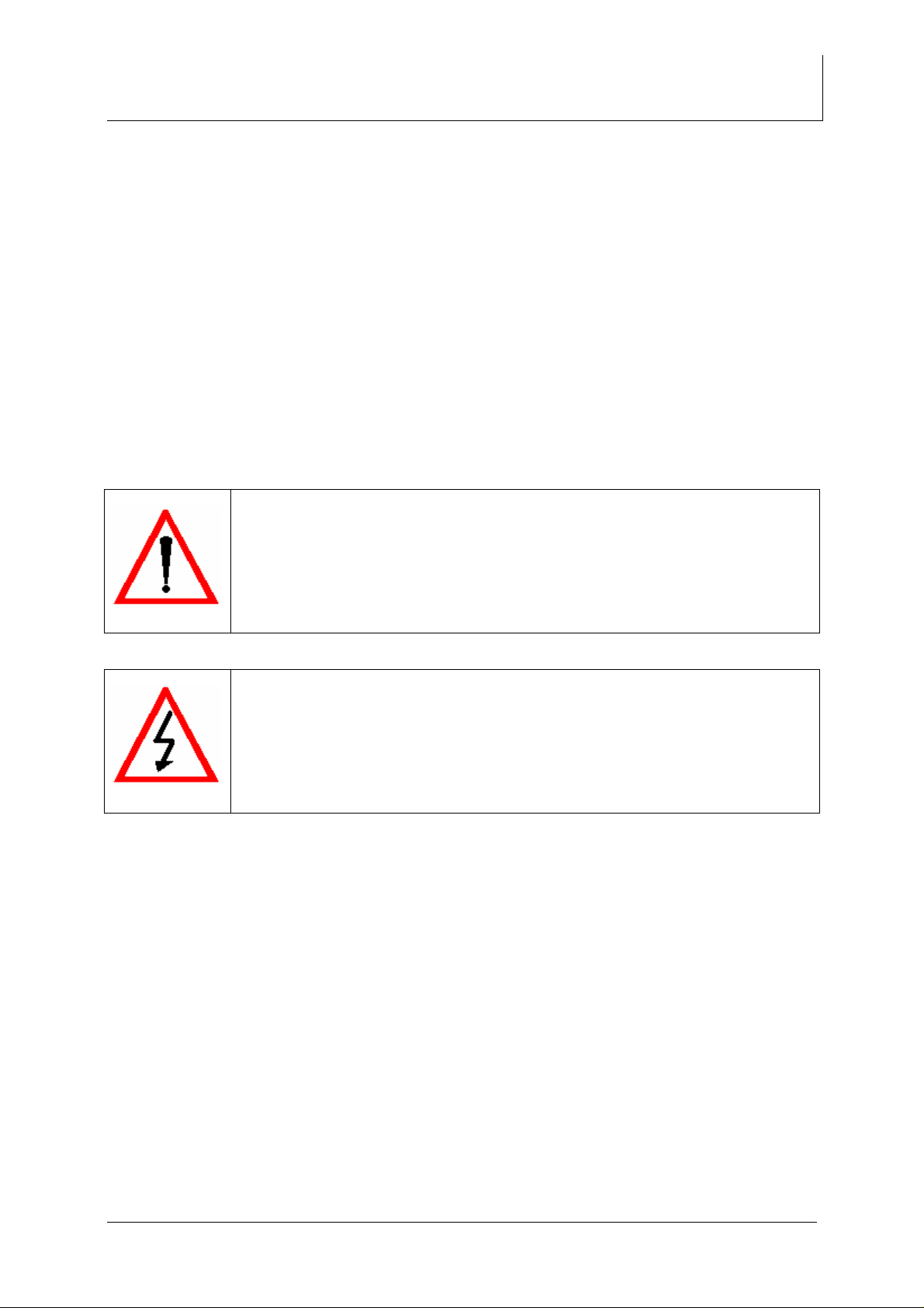
2.1. Drive
Single phase low-noise AC motor
•
with thermal cut-out
2.2. Transmission and brake
• Worm-gearbox built directly onto the
driving motor
• The worm-wheel reduction forms an affective
brake for the (loaded) StairRobot on the staircase
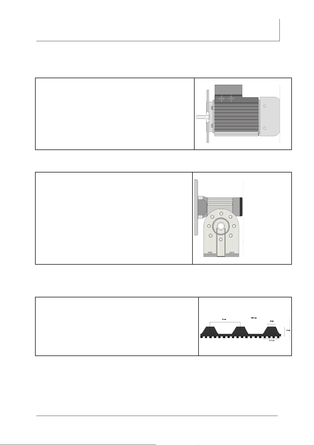
2. 3. Tracks
• Internally and externally toothed caterpillar tracks,
specially designed for smooth stair climbing
Page 7 of 28
Page 8
AATA INTERNATIONAL B.V.
2. 4. Controls
• Remote control (2 metres cable attached) manually
operated 4-button switch
Press a button to drive
Manual Stair Robot SR1750 HE
Publication: 29-07-04
2. 5. Hydraulic-levelling platform
• To increase stability the platform can be adjusted to the angle of the staircase by a
hydraulic cylinder
Page 8 of 28
Page 9

AATA INTERNATIONAL B.V.
2. 6. Descent adjuster
2.7. Hydraulic motor and pump
Manual Stair Robot SR1750 HE
Publication: 29-07-04
The descent adjuster is located at the rear end of
•
the machine and is used to adjust the descent of
the lifting platform depending on the weight of the
load.
Turn maximum clockwise for speed : 0
•
The hydraulic-motor is placed on the drive
•
motor with the pump built directly onto the
motor
3. Ancillary equipment
3.1. Loading ramp
• The loading ramp is designed to fit neatly
into the stairrobots lifting platform. It
provides a safe ridged platform to transport
the load from the floor-surface to the loadposition on the robot.
Page 9 of 28
Page 10

AATA INTERNATIONAL B.V.
3.2. Turntable
•
The turntable is a circular piece of
equipment Ø 610 mm, h. 40 mm.
constructed out-of two disks of
block board with hard-plastic
surface to eliminate friction. It is
used to alter the direction of travel
for the (loaded) StairRobot. There
are finger grips on either side for
easy lifting or carrying.
3.3. Winch
•
The winch is designed to fit into the lifting platform of the stairrobot. With the winch a
load can be pulled onto the platform with a minimum amount of effort
Manual Stair Robot SR1750 HE
Publication: 29-07-04
Page 10 of 28
Page 11

AATA INTERNATIONAL B.V.
3.4. Dolly
•
The dolly is constructed of square steel fittings with four heavy-duty swivel wheels
for easy movements. An extendable frame can be pulled out to increase stability
while driving the StairRobot on the dolly. The lead-off ramp is used to connect the
dolly with the stairway
Manual Stair Robot SR1750 HE
Publication: 29-07-04
Page 11 of 28
Page 12

AATA INTERNATIONAL B.V.
4. Safety
4.1. General safety precaution
Manual Stair Robot SR1750 HE
Publication: 29-07-04
•
It is not permitted to make alterations to the
machine.
•
Everybody who is working with the machine
has to be acquainted with the safety rules and
has to act upon them.
•
Two operators are required to operate the
stairrobot
•
Always check the surroundings where the
stair-robot will be deployed.
•
Assure that the angle of the stairs is not more
than 45 º
• • Make sure that no operator or other person is underneath the (loaded) Stairrobot
during operation
Secure the working area using warning boards or blocking ribbon
Page 12 of 28
Page 13

AATA INTERNATIONAL B.V.
Manual Stair Robot SR1750 HE
Publication: 29-07-04
•
To avoid misuse by unauthorised persons,
don’t leave the machine unattended.
•
Within the path of the machine there may be
no obstructions.
•
Make sure the environment of the machine is
dry, clean and illuminated sufficiently.
•
With the machine in operation it is forbidden to
be within the operation area of this apparatus.
•
Before taking the machine into operation the
machine operator has to be certain that
nobody is located within the operating area of
the machine.
•
If the machine is used into the darkness, the
operation position has to be illuminated
sufficiently (about 50 lux).
•
The machine may only be used for the
intended activities.
•
Inspection and maintenance activities have to
be done before operation
•
During inspection and maintenance the
machine may not be used for other purposes
•
The local action and safety rules have to be
acted upon.
•
Make sure you never walk under the robot
during operation.
•
Keep electrical switch boxes closed in order to
prevent contact danger.
•
Never drive the machine over a cable or
extension cord
•
Make sure the mains connection is grounded
properly
•
Make sure that no person stands on a cable
or extension cord
•
Make sure that the extension cord is unrolled
completely
•
Extension cord minimal requirements: 3x 2,5
mm cupper wire properly isolated
•
Extension cord must be no longer than 25
meters.
Page 13 of 28
Page 14

AATA INTERNATIONAL B.V.
Manual Stair Robot SR1750 HE
Publication: 29-07-04
5 OPERATORS PROCEDURE
5.1. Pre-use inspection
To ensure proper working and safe operation of the SR 1750 HE StairRobot:
• Check that there are no exposed wires in either the main lead or the pendant control
• Check that both the main plug and the continental 16 amp plug and socket are all
secure
• Check that the pendant cable is secure in the pendant and at the machine end
• Check that no cable has been deformed. If a deformation is found the use of the
machine should be postponed until the cable has been repaired
• If on the dolly; drive the robot of the dolly on a flat surface, listen for excessive or
unusual noises from any part of the machine
• Check that the ramp will raise to it’s full extend and that it’s not leaking oil. When fully
extended the ramp should cause the platform’s front edges to be in firm contact with
the floor and the tracks to be lifted of the floor at the front end about one centimetre
• Irregularities are best noticed by rising the ramp repeatedly to it’s full up position and
then quickly pressing the down button to release the pressure. If, while the ramp is
fully extended the top of the cylinder moves more than 5 mm either towards the front
or the back of the Robot then the machine should not be used
• It is quite usual for some oil to be present around the top of the cylinder, however
with the up-button pressed and the pump running there should be no oil running
down the outside of the cylinder
• Check that the down-button permits the ramp to descend, and in addition check that
the descend adjuster permits the speed of the descend to be altered. From fully
extended to fully closed should take no less than 25 seconds with an applied load of
80 Kilogram with the ascend adjuster turned maximum counter clockwise
• Check that no rubber blocks on the tracks are severely damaged or torn off
• Check the drive-tooth side of the tracks for exposed stringing cords or damage
• Check that nothing has been trapped between the tracks and the robot
• Check that when going from forward to reverse direction on the pendant button the
delay before the tracks start moving in the opposite direction is no longer than one
second. Any longer time indicates sloppiness in the drive chain which should be
investigated
• Check that the platform sits down on the lower base when lowered
• Check that the castors of the dolly can move in all directions and are not jammed
Check that the cable of the winch has not been deformed
•
If there are no defects found the machine is ready for use. If a defect is found do not use the
machine until the Stair-Robot is repaired.
Page 14 of 28
Page 15

AATA INTERNATIONAL B.V.
Manual Stair Robot SR1750 HE
Publication: 29-07-04
5.2. Loading
5.2.1 The correct position of the load
• The objective is to create an optimal centre of gravity position for the loaded stairrobot
considering the ‘weight distribution’ of the load
• If the load is not placed in the correct position on the lifting
platform, the Stair robot can get instable during the process of
climbing or descending a staircase. This can cause the robot to
fall down the stairs resulting in serious damage and injuries.
• Before positioning the load on the
lifting platform the centre of gravity of
the load has to be determined
• Position the load on the platform with
the centre of gravity of the load end
forward (in positive area)
• Position the load with the centre of
gravity of the load as low as possible
to the lifting platform.
Page 15 of 28
Page 16

AATA INTERNATIONAL B.V.
5.2.2. Loading procedure
• Start the procedure by securing the area for loading. Move the dolly with the stair
robot into the desired position for loading.
• Always unroll extension power cable and connect with the robot before connecting
to mains
• Reverse the Robot of the dolly, fit the loading-ramp into position at the front of the
robot
• Slot the winch into the lifting platform at the rear of the stairrobot
• Pull the winch-hawser out and connect it with the load. The load can now be
winched into position on the stairrobot, one man operating the winch and one man
guiding the load of the ramp onto the platform. While operating the winch the
lifting platform will rise until the platform has reached the same gradient as the
loading-ramp
• Connect the load secure to the lifting platform. Note: never fit any straps to the
chassis-bracket
• If the load is secured to the stairrobot the winch and loading ramp can be
removed
• Always remove the winch from the stairrobot before ascending the stairway
because it ads length to the dimensions of the stairrobot
• Turn the descent-adjuster maximum clockwise
• Lift the platform +/- 10 cm by pushing the up-button
• Push the down-button to lower the platform and turn the descent adjuster counter
clockwise until the platform starts to descent. Lower the platform
• The stairrobot can now be driven back on the dolly; use the up-button to keep the
‘platform level’ in horizontal position
Manual Stair Robot SR1750 HE
Publication: 29-07-04
• The centre of gravity of the load should
be within the positive area between the
tracks.
Page 16 of 28
Page 17

AATA INTERNATIONAL B.V.
Manual Stair Robot SR1750 HE
Publication: 29-07-04
5.3. Ascending
Load level
• Ideal load level is obtained
by adjusting the platform to
the gradient of the stairs or
dolly
• The objective is to maintain
a horizontal level of the
platform during operation.
• Note: do not lower the platform
over its balance point, the Stair
robot will get instable during
the process of climbing or
descending a staircase. This
can cause the robot to fall
down the stairs resulting in
serious damage and injuries.
• Move the loaded stairrobot on the dolly with the forward end towards the bottom of
the stairs
• Fit the lead on ramp between the dolly and second or third step on the stairs.
• Secure a load support strap (6 m) to the reverse end of the stairrobot. Place the strap
across the forward end of the load to be held by one of the operators.
• Both operators should move on to the stairs and make sure that no person is beneath
the stairrobot
• One operator will use the remote control button panel and drive the loaded stairrobot
up the stairs. The other will firmly hold the load support strap; this will enable him to
‘feel’ the balance of the load. He also uses it to restrain the load if necessary and
helps its forward movement at the top of the stairs
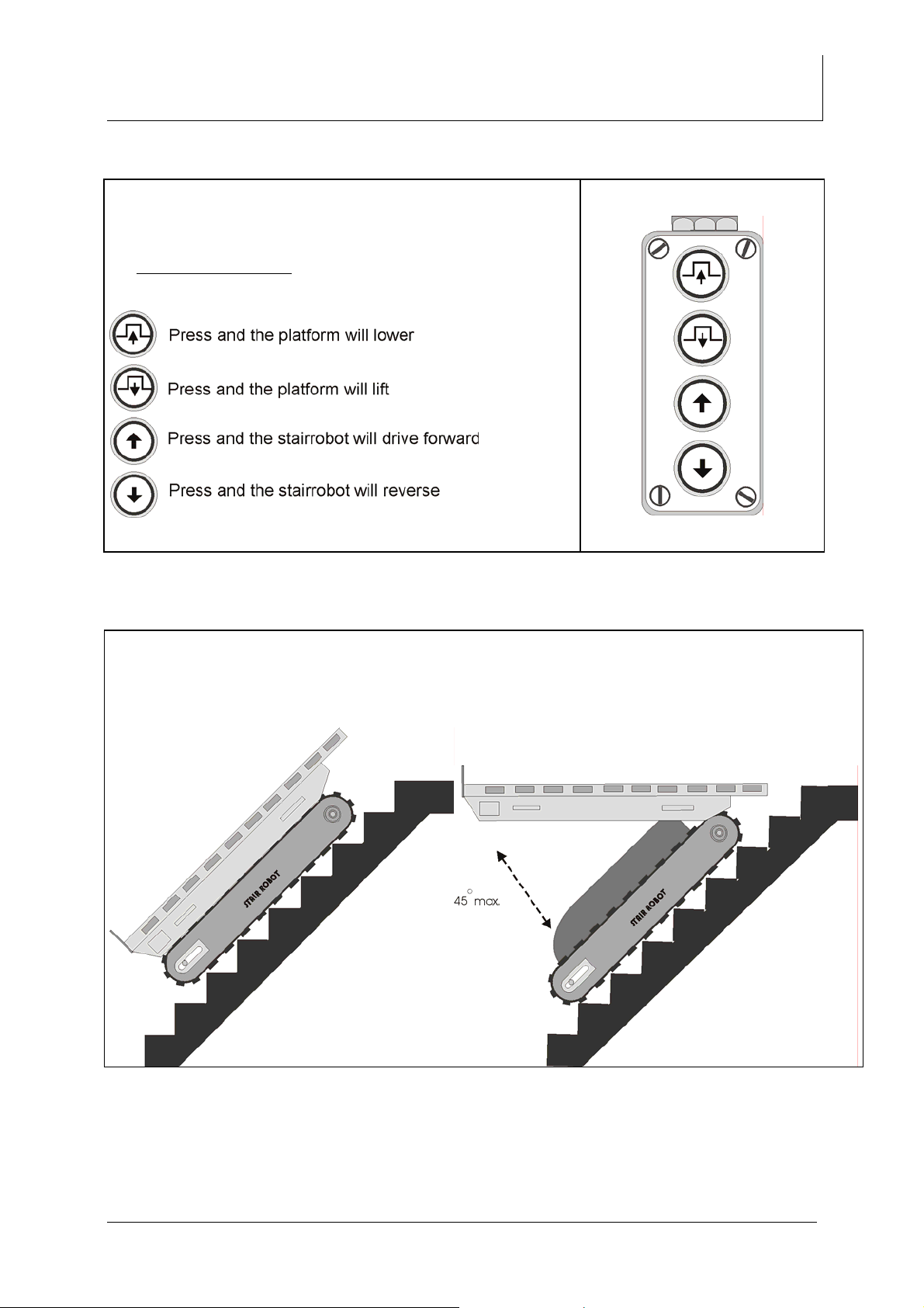
• The control operator will press the forward button to drive the stairrobot over the lead
on ramp and up the stairs. He will keep the load level by adjusting the platform
position using the up or down button.
• The up or down button can be pressed simultaneously with either forward or reverse
Press an d the platform will lower
Press an d the platform will lift
Press an d t he stairr obot will driv e forward
Press an d t he stairr obot will rev e rs e
Page 17 of 28
Page 18

AATA INTERNATIONAL B.V.
Manual Stair Robot SR1750 HE
Publication: 29-07-04
• The stair robot can be stopped at any stage by just releasing the buttons
• When arriving on top of the stairway; stop the stairrobot on the stairs and place the
dolly in position at the top of the stairs in front of the stairrobot. Pull the extendable
frame out of the dolly to increase stability
• Start the forward movement again
• Note: expect a change of gradient from the level of the stairs to the gradient of the
dolly
• When the stairrobot has reached the ‘point of balance’, the operator holding the load
support strap should assist in the movement by gently pulling the load support strap,
to ease the load downward. The other operator should keep the ideal load level
during this operation. The stairrobot can then be driven forward to settle onto the dolly
• Transport dolly and load to the unloading point or to the next flight of stairs to
continue upwards.
5.4. Descending
• Make sure that the stairway is secured and no person can enter the stairway.
• To descent the stairrobot down the stairway the loaded stairrobot has to be first
driven onto the dolly, as previously described for ascending
• Move the loaded stairrobot on the dolly with the downward end towards the edge of
the top of the step and stop 10 cm away.
• One operator will drive the stairrobot using the control panel while the other operator
will steady the load firmly using a load support strap.
• Press the reverse button to drive the robot from the dolly and down the stairs
• The up and down button is used to maintain ideal load level
• By reversing slowly, 5 cm at a time, and stopping at the ‘point of balance’ the control
operator will be able by pressing the up button gently alter the centre of gravity so as
to lower the reverse end tracks onto the top of the stairs.
• The dolly should be moved aside when the stairrobot is fully on the stairs.
• Drive the robot in reverse down the stairs steadying the movement throughout by
using the a load support strap
• Depending on the gradient, the stair robot will ride on the edge of two or three steps
at once. The rubber tracks pressing firmly onto the stairs
• On some stairs it may be found that occasionally two of the rubber treads ride on the
stair edge and when the third tread releases it’s grip the stairrobot will move down
suddenly about 2,5 cm until all three treads grip once more. This occurrence should
be expected by the operators and the stair robot should be driven on without a pause
• Before arriving at the bottom of the stairs the dolly and the lead on ramp should be
placed in position with the lead on ramp resting on the second or third step.
• Drive the stairrobot of the stairs and onto the dolly keeping the ideal load level by
using the up or down button
• Transport dolly and load to the unloading point or to the next flight of stairs to
continue downwards.
Page 18 of 28
Page 19

AATA INTERNATIONAL B.V.
5.5. Unloading
• Start the procedure by securing the area for unloading. Move the dolly with the
stair robot into the desired position for unloading.
• Reverse the Robot of the dolly, fit the loading-ramp into position at the front of the
robot
• Slot the winch into the lifting platform at the rear of the stairrobot
• Pull the winch-hawser out and connect it with the load. Disconnect the load from
the lifting platform
• The load can now be lowered to floor level, one man operating the winch and one
man guiding the load of the ramp onto the floor. While lowering the load the lifting
platform will rise until the platform has reached the same gradient as the loadingramp
• If the load is on the floor the winch and loading ramp can be removed
l these techniques should be practised with a light load first
• Al
Manual Stair Robot SR1750 HE
Publication: 29-07-04
Page 19 of 28
Page 20

AATA INTERNATIONAL B.V.
Manual Stair Robot SR1750 HE
Publication: 29-07-04
6 Trouble shooting chart
The stairrobot SR 1750 HE is designed and built to function for several years with little
maintenance. In case a problem occurs please make the following checks. If the problem
continues to exist please contact your local dealer
Symptom
• Main motor does
not work
Possible course
• No current
Solution
• Check electrical wires
and connections
• Check magneto
switches
• Check capacitors
• Hydraulic pump-
motor does not
work
• Main motor stops
• Hydraulic pump-
motor stops
• Hydraulic platform
does not lift
completely
• Hydraulic platform
does not go down
• No current
• Motor overheated
• Motor overheated
• Possible oil-shortage
• Pressure relieve valve
• Electro-magneto switch
does not work properly
• Check electrical wires
and connections
• Check magneto
switches
• Check capacitors
• Wait several minutes
• Wait several minutes
• Refill oil with spindle oil;
check oil in oil-tank;
should be 5 mm under
the top of the tank
• Open valve by turning it
counter clockwise,
move the platform up
and down a few times;
adjust the valve to the
weight of the load
• Check electrical wiring
and connections
Page 20 of 28
Page 21

AATA INTERNATIONAL B.V.
Symptom
• Oil leaks from
hydraulic ram
• Hydraulic platform
does not move up
Possible course
• Ram packing worn
• Plunger bent
• Under pressure in
hydraulic system
Manual Stair Robot SR1750 HE
Publication: 29-07-04
Solution
• Replace o-ring and
back-up ring with repair
set
• Remove the wood
plate of the lifting
platform and unscrew
the valve on the oiltank pipe; move the
platform in up position
by hand and turn valve
screw tight
Page 21 of 28
Page 22

AATA INTERNATIONAL B.V.
7 Track replacement
• Loosen both bolts a1 and a2
• Turn bolts b1 and b2 counter clockwise until the axle is at point d
• Remove track at point C
• To install the new track, reverse the above procedure
Drawing (1.)
Manual Stair Robot SR1750 HE
Publication: 29-07-04
Drawing (2.)
• After replacing tracks make sure that the > marks on both tracks are in
the in the same direction and position
Page 22 of 28
Page 23

AATA INTERNATIONAL B.V.
Manual Stair Robot SR1750 HE
Publication: 29-07-04
• Proper track tolerance at point F is +/- 10 mm (pulled by hand) drawing (3.)
• Make sure that the distances A1 ….A4 are equal on both sides of the
Stairrobot (drawing 4)
Drawing (3.)
Drawing (4.)
Page 23 of 28
Page 24

AATA INTERNATIONAL B.V.
8 Electrical system
Manual Stair Robot SR1750 HE
Publication: 29-07-04
Page 24 of 28
Page 25

AATA INTERNATIONAL B.V.
9 Hydraulic system
Manual Stair Robot SR1750 HE
Publication: 29-07-04
Page 25 of 28
Page 26

AATA INTERNATIONAL B.V.
10. Parts
Manual Stair Robot SR1750 HE
Publication: 29-07-04
Page 26 of 28
Page 27

AATA INTERNATIONAL B.V.
10.1. Parts list
Art.nr.: Article
175.001A Main motor
175.001B Gearbox
175.002 Hydro-motor
175.003 Hydro-pump
175.003B Oil-seal hydro pump
175.007 4-button switch unit
175.008 Magneto switch
175.009 Transformer 220V/24V
175.011 Oil tank
175.012 Caterpillar wheel Rear
175.013 Caterpillar wheel Front
175.014 Front axle
175.015 Rear axle
175.016 Drive axle
175.017 Gearwheel 11 T
175.018 Gearwheel 38 T
175.019 Gearwheel 20 T
175.020 Bearing axle 30
175.021 Bearing axle 20
175.022 Lock ring
175.023 Teflon 303635
175.024 Teflon304030
175.032 Bearing holder
175.033 Teflon ring 51312
175.040 Top cross beam
175.041 Bottom cross beam
175.042 Hydro-ram
175.043 Filter
175.044 Relief valve
175.045 Main selector valve
175.046 Electro-unit
175.050 Capacitor 8uf
175.051 Capacitor 100 uf
175.077 Hydro-pipe set
175.100 Caterpillar track
175.101 Dolly
175.102 Ramp-board
175.103 Turn disk
175.104 Winch
175.105 Winch-handle
Manual Stair Robot SR1750 HE
Publication: 29-07-04
Page 27 of 28
Page 28

AATA INTERNATIONAL B.V.
11. CD-Rom video
Content:
• Stair robot general promotion video (mpeg1)
• Instruction video SR 1750 HE (mpeg1)
• Instruction video SR 450 (mpeg1)
Manual Stair Robot SR1750 HE
Publication: 29-07-04
cd-rom
Page 28 of 28
 Loading...