

Page 1
POWERTECH 8.1 L
Diesel Engines
Base Engine
COMPONENT
TECHNICAL
MANUAL
For complete service information also see:
Deere Power Systems Group
CTM86 (20MAR01)
LITHO IN U.S.A.
ENGLISH
Page 2

Foreword
Introduction
This manual is written for an experienced technician.
Essential tools required in performing certain service
work are identified in this manual and are
recommended for use.
This manual (CTM86) covers only the base engine. It
is one of five volumes on 8.1 L engines. The following
four companion manuals cover fuel system repair and
diagnostics:
• CTM243—Mechanical Fuel Systems
• CTM134—Level 3 Electronic Fuel Systems
• CTM255—Level 9 Electronic Fuel Systems
• CTM68—Electronic Injection Fuel Systems
Other manuals will be added in the future to provide
additional information on electronic fuel systems as
needed.
A set of all manuals covering the 8.1 L engines, except
CTM68, can be obtained by purchasing CTM450
Binder Set.
Live with safety: Read the safety messages in the
introduction of this manual and the cautions presented
throughout the text of the manual.
applicable essential tools, service equipment, and
other materials needed to do the job, service parts kits,
specifications, wear tolerance, and torque values.
Before beginning repair on an engine, clean the engine
and mount on a repair stand. (See CLEAN ENGINE in
Group 010 and see MOUNT ENGINE ON REPAIR
STAND in Group 010..)
This manual contains SI Metric units of measure
followed immediately by the U.S. Customary units of
measure. Most hardware on these engines is metric
sized.
Some components of this engine may be serviced
without removing the engine from the machine. Refer
to the specific machine technical manual for
information on components that can be serviced
without removing the engine from the machine and for
engine removal and installation procedures.
Read each block of material completely before
performing service to check for differences in
procedures that apply to the engine model number you
are working on. If only one procedure is given, that
procedure applies to all the engines in the manual.
This is the safety-alert symbol. When you see this
symbol on the machine or in this manual, be alert to
the potential for personal injury.
Use this component technical manual in conjunction
with the machine technical manual. An application
listing in the introduction identifies
engine-models/applications. See the machine technical
manual for information on engine removal and
installation, and gaining access to engine components.
Information is organized in sections and groups for the
various components requiring service instruction. At
the end of the book are summary listings of all
Component Technical Manuals are concise service
guides for specific components. Component technical
manuals are written as stand-alone manuals covering
multiple machine applications.
Fundamental service information is available from
other sources covering basic theory of operation,
fundamentals of troubleshooting, general maintenance,
and basic types of failures and their causes.
CALIFORNIA PROPOSITION 65 WARNING: Diesel
engine exhaust and some of its constituents are
known to the State of California to cause cancer,
birth defects, and other reproductive harm.
CTM86 (20MAR01) P
OWERTECH
DPSG,OUO1004,912 –19–15JUN99–1/1
8.1 L Diesel Engines — Base Engine
032001
PN=2
Page 3

John Deere Dealers
Introduction
The changes listed below make your CTM obsolete.
Repair, operation, and diagnostics are now covered in
five manuals. Discard CTM86 dated 06JUL99 and
replace with the following new manuals:
• CTM86—Base Engine
• CTM243—Mechanical Fuel Systems
• CTM134—Level 3 Electronic Fuel Systems
• CTM255—Level 9 Electronic Fuel Systems
• CTM68—Electronic Fuel Injection Systems
Also, copy these pages and route through your Service
Department.
SECTION 01, GROUP 001 (Engine Identification)
• Updated engine model designation chart.
• Updated engine application charts.
SECTION 01, GROUP 002 (Fuels, Lubricants, and
Coolants)
• Updated engine oil and coolant application
guidelines.
SECTION 02, GROUP 050 (Camshaft and Timing
Gear Train Repair and Adjustment)
• Eliminated procedure to check valve lift. Use
appropriate procedure from Group 020 or Group
021.
• Revised specifications for installation of crankshaft
gear-driven auxiliary drive.
• Revised procedure for installation of thrust washer
and timing gear cover.
SECTION 02, GROUP 060 (Lubrication System
Repair and Adjustment)
• Added information for top-load oil filter.
SECTION 02, GROUP 070 (Cooling System Repair
and Adjustment)
• Added belt routing diagrams.
• Revised procedure for installation of coolant pump.
SECTION 02, GROUP 080 (Air Intake and Exhaust
System Repair and Adjustments)
SECTION 02, GROUP 010 (Engine Rebuild)
• Updated engine disassembly sequence.
• Updated engine assembly sequence.
• Updated sealant application guidelines.
SECTION 02, GROUP 020 (Cylinder Head and
Valves Repair and Adjustment Serial Number
( —199,999)
• Repair procedures for cylinder head and valves on
engines with serial number ( —199,999) are covered
in this group.
SECTION 02, GROUP 021 (Cylinder Head and
Valves Repair and Adjustment Serial Number
(200,000— )
• Repair procedures for cylinder head and valves on
engines with serial number (200,000— ) are covered
in this group.
• Revised procedure for turbocharger inspection
techniques.
• Eliminated procedure for adjusting turbocharger
wastegate actuator.
• Revised specifications for installing turbocharger.
SECTION 02, GROUP 090 (Fuel System Repair and
Adjustments)
NOTE: Repair procedures for fuel systems have been
have been moved to Section 02, Group 090 in
the three following technical manuals:
•
CTM243—Mechanical Fuel Systems
•
CTM134—Level 3 Electronic Fuel Systems
•
CTM255—Level 9 Electronic Fuel Systems
SECTION 02, GROUP 100 (OEM Starting and
Charging Systems)
CTM86 (20MAR01) P
OWERTECH
DPSG,OUO1004,898 –19–19MAY99–1/2
8.1 L Diesel Engines — Base Engine
032001
PN=3
Page 4

Introduction
• Starting and charging systems are covered in this
new group.
SECTION 03, GROUP 120 (Base Engine Operation)
• Base engine theory of operation is covered in this
new group.
NOTE: Fuel system theory of operation has been
moved to Section 03 in the three following
technical manuals:
•
CTM243—Mechanical Fuel Systems
•
CTM134—Level 3 Electronic Fuel Systems
•
CTM255—Level 9 Electronic Fuel Systems
SECTION 04, GROUP 150 (Observable Diagnostics
and Tests)
• Base engine observable diagnostics and tests are
covered in this new section/group.
NOTE: Fuel system diagnostics and testing has been
moved to Section 04 in the three following
technical manuals:
•
CTM243—Mechanical Fuel Systems
•
CTM134—Level 3 Electronic Fuel Systems
•
CTM255—Level 9 Electronic Fuel Systems
SECTION 05 (Tools and Other Materials)
• All essential tools, service tools, dealer fabricated
tools, and other materials listed throughout this
manual are consolidated in this section for ease of
reference.
SECTION 06 (Specifications)
• All repair, test, and diagnostic specifications listed
throughout this manual are consolidated in this
section for ease of reference.
• Updated bolt and cap screw torque values.
• Updated General OEM specifications.
• Updated dynamometer specifications.
• Updated turbocharger boost specifications
CTM86 (20MAR01) P
OWERTECH
DPSG,OUO1004,898 –19–19MAY99–2/2
8.1 L Diesel Engines — Base Engine
032001
PN=4
Page 5

About this Manual
Introduction
This component technical manual (CTM) covers the base
engine for P
OWERTECH
8.1 L (494 cu. in.) diesel engines
produced in Waterloo, Iowa.
This manual is a complete revision of CTM86
(06JUL99). Replace earlier manual with the following new
manuals:
• CTM86 — P
OWERTECH
8.1 L Diesel Engines—Base
Engine
• CTM243 — P
OWERTECH
8.1 L Diesel Engines—
Mechanical Fuel Systems
• CTM134 — P
OWERTECH
6.8 L & 8.1 L Diesel
Engines—Level 3 Electronic Fuel Systems with Bosch
In-Line Pump
• CTM255 — 8.1 L Diesel Engines—Level 9 Electronic
Fuel Systems with Denso In-Line Pump
• CTM68 —Electronic Fuel Injection Systems
Direction of engine crankshaft rotation in this manual is
referenced facing the flywheel looking toward the fan.
Front of engine is fan drive end.
Read each procedure completely before performing any
service.
IMPORTANT: For repair, diagnostics, and testing
procedures on the fuel system, refer to
the companion manuals:
• CTM243 — P
OWERTECH
8.1 L Diesel
Engines—Mechanical Fuel Systems
• CTM134 — P
OWERTECH
6.8 L & 8.1 L
Diesel Engines—Level 3 Electronic
Fuel Systems with Bosch In-Line
Pump
• CTM255 — 8.1 L Diesel Engines—
Level 9 Electronic Fuel Systems with
Denso In-Line Pump
• CTM68 —Electronic Fuel Injection
Systems
P
OWERTECH
is a registered trademark of Deere & Company
CTM86 (20MAR01) P
OWERTECH
DPSG,OUO1004,913 –19–15JUN99–1/1
8.1 L Diesel Engines — Base Engine
032001
PN=5
Page 6
Introduction
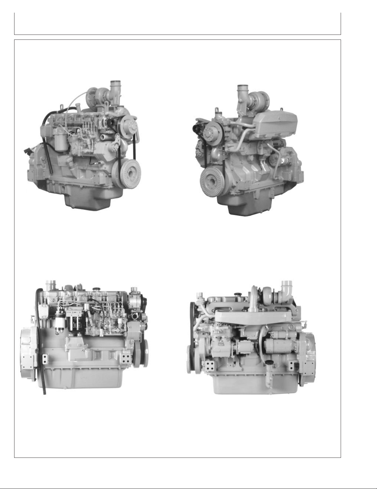
Identification Views Serial Number ( —199,999)
8.1 L Diesel Engine Right Front View (Engines —199,999)
RG7362 –UN–05JAN98
8.1 L Diesel Engines Left Front View (Engines —199,999)
RG7363 –UN–05JAN98
8.1 L Diesel Engines Right Side View (Engines —199,999)
RG7385 –UN–05JAN98
8.1 L Diesel Engines Left Side View (Engines —199,999)
CTM86 (20MAR01) P
OWERTECH
RG7387 –UN–05JAN98
RG,RG34710,4001 –19–14DEC00–1/2
8.1 L Diesel Engines — Base Engine
032001
PN=6
Page 7
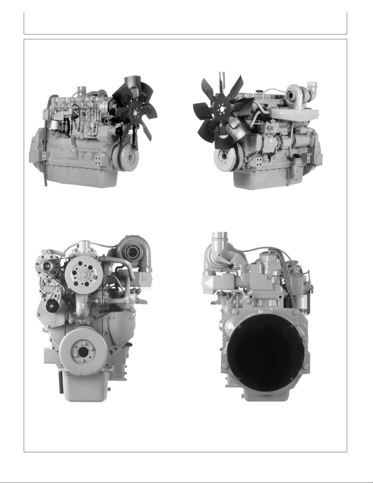
Introduction
8.1 L Diesel Engine Right Front View (Engines —199,999)
RG7388 –UN–20JUN00
8.1 L Diesel Engine Left Front View (Engines —199,999)
RG7386 –UN–20JUN00
8.1 L Diesel Engine Front View (Engines —199,999)
RG7383 –UN–05JAN98
8.1 L Diesel Engine Rear View (Engines —199,999)
CTM86 (20MAR01) P
OWERTECH
RG7384 –UN–05JAN98
RG,RG34710,4001 –19–14DEC00–2/2
8.1 L Diesel Engines — Base Engine
032001
PN=7
Page 8
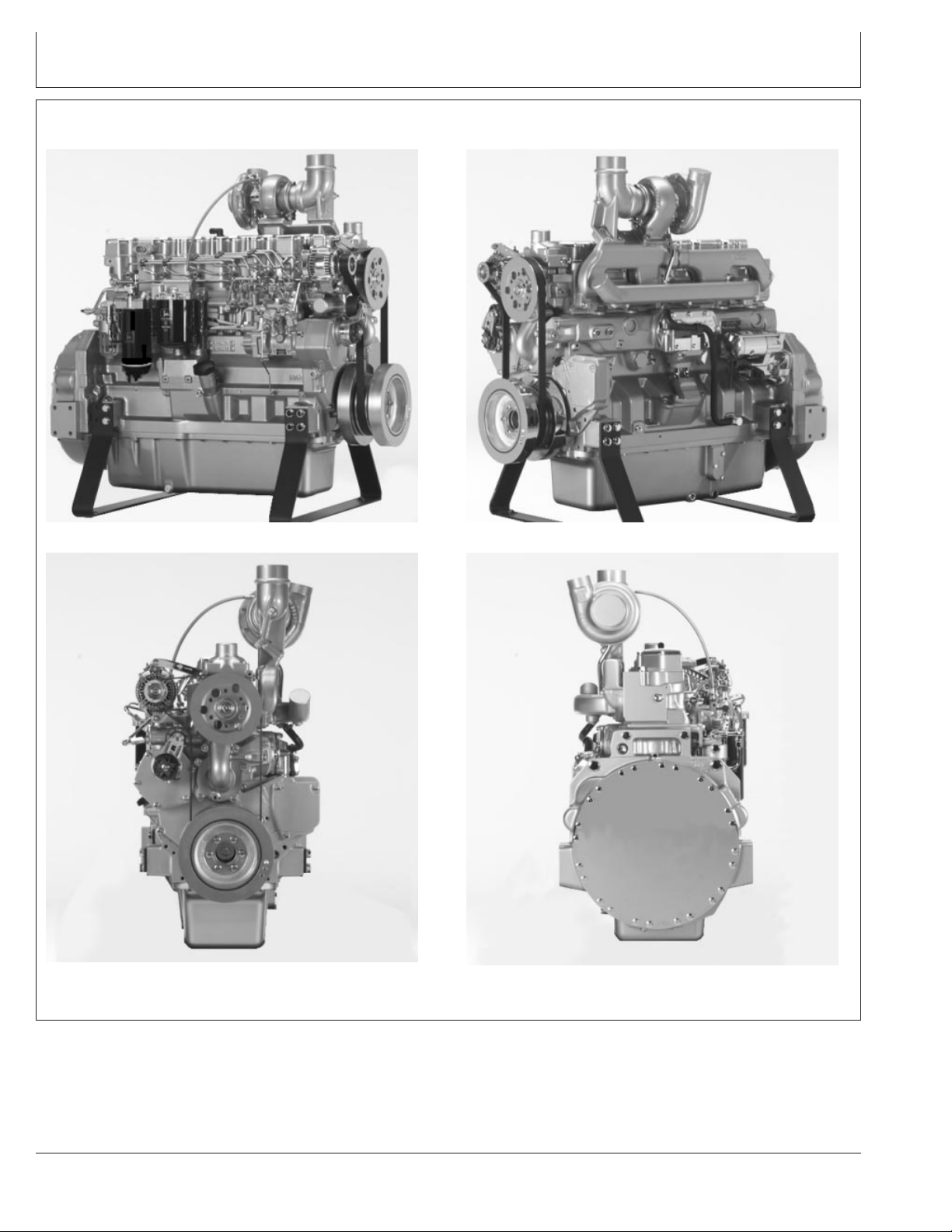
Introduction
Identification Views Serial Number (200,000— )
8.1 L Diesel Engine Right Front View (Engines 200,000— )
8.1 L Diesel Engine Front View (Engines 200,000— )
RG11511 –UN–13DEC00
RG11513 –UN–31OCT00
8.1 L Diesel Engines Left Front View (Engines 200,000— )
RG11512 –UN–31OCT00
RG11514 –UN–31OCT00
8.1 L Diesel Engine Rear View (Engines 200,000— )
CTM86 (20MAR01) P
OWERTECH
RG,OUOD007,4002 –19–01NOV00–1/1
8.1 L Diesel Engines — Base Engine
032001
PN=8
Page 9

SECTION 01—General
Group 000—Safety
Group 001—Engine Identification
Group 002—Fuels, Lubricants and Coolant
Contents
01
SECTION 02—Repair and Adjustments
Group 010—Engine Rebuild
Group 020—Cylinder Head and Valves Repair and
Adjustment S. N. ( —199,999)
Group 021—Cylinder Head and Valves Repair and
Adjustment S. N. (200,000— )
Group 030—Cylinder Block, Liners, Pistons, and
Rods Repair and Adjustment
Group 040—Crankshaft, Main Bearings and
Flywheel Repair and Adjustment
Group 050—Camshaft and Timing Gear Train
Repair and Adjustment
Group 060—Lubrication System Repair and
Adjustment
Group 070—Cooling System Repair and Adjustment
Group 080—Air Intake and Exhaust System Repair
and Adjustment
Group 100—OEM Starting and Charging Systems
Repair and Adjustment
SECTION 03—Theory of Operation
Group 120—Base Engine Operation
SECTION 04—Diagnostics
Group 150—Observable Diagnostics and Tests
02
03
04
05
06
SECTION 05—Tools and Other Materials
Group 170—Repair Tools and Other Materials
Group 180—Diagnostic Service Tools
Group 190—Dealer Fabricated Service Tools
SECTION 06—Specifications
Group 200—Repair and General OEM
Specifications
Group 210—Diagnostic Specifications
All information, illustrations and specifications in this manual are based on
the latest information available at the time of publication. The right is
reserved to make changes at any time without notice.
COPYRIGHT2001
DEERE & COMPANY
Moline, Illinois
A John Deere ILLUSTRUCTIONManual
All rights reserved
Previous Editions
Copyright1994,1997,1999
INDX
CTM86 (20MAR01)
i
P
OWERTECH
8.1 L Diesel Engines — Base Engine
032001
PN=1
Page 10

01
02
03
04
05
Contents
06
INDX
CTM86 (20MAR01)
ii
P
OWERTECH
8.1 L Diesel Engines — Base Engine
032001
PN=2
Page 11

Page
Group 000—Safety ....................01-000-1
Group 001—Engine Identification
Engine Model Designation................01-001-1
Engine Serial Number Plate Information .....01-001-2
Engine Option Code Label ...............01-001-3
Engine Application Chart (John Deere
Agricultural Equipment) ................01-001-4
Engine Application Chart (John Deere
Construction Equipment) ...............01-001-5
Engine Application Chart (OEM) (Outside
Equipment Manufacturers)..............01-001-5
Group 002—Fuels, Lubricants and Coolant
Diesel Fuel ...........................01-002-1
Bio-Diesel Fuel ........................01-002-2
Lubricity of Diesel Fuel ..................01-002-4
Dieselscan Fuel Analysis.................01-002-4
Diesel Engine Break-In Oil ...............01-002-5
Diesel Engine Oil ......................01-002-6
Extended Diesel Engine Oil Service
Intervals............................01-002-6
Alternative and Synthetic Lubricants ........01-002-7
Mixing of Lubricants ....................01-002-7
Oilscan and Coolscan ...................01-002-8
Grease ..............................01-002-9
Diesel Engine Coolant..................01-002-10
Diesel Engine Coolants, Supplemental
Additive Information..................01-002-11
Testing Diesel Engine Coolant ...........01-002-12
Replenishing Supplemental Coolant
Additives (SCAs) Between Coolant
Changes ..........................01-002-13
Operating in Warm Temperature Climates . .01-002-14
Flush and Service Cooling System ........01-002-15
Disposing of Coolant...................01-002-16
01
Section 01
General
Contents
CTM86 (20MAR01)
01-1
P
OWERTECH
8.1 L Diesel Engines — Base Engine
032001
PN=1
Page 12

01
Contents
CTM86 (20MAR01)
01-2
P
OWERTECH
8.1 L Diesel Engines — Base Engine
032001
PN=2
Page 13
Handle Fluids Safely—Avoid Fires
When you work around fuel, do not smoke or work near
heaters or other fire hazards.
Store flammable fluids away from fire hazards. Do not
incinerate or puncture pressurized containers.
Make sure machine is clean of trash, grease, and debris.
Do not store oily rags; they can ignite and burn
spontaneously.
Group 000
Safety
01
000
1
TS227 –UN–23AUG88
Avoid Fires
DX,FLAME –19–29SEP98–1/1
Handle Starting Fluid Safely
Starting fluid is highly flammable.
Keep all sparks and flame away when using it. Keep
starting fluid away from batteries and cables.
To prevent accidental discharge when storing the
pressurized can, keep the cap on the container, and store
in a cool, protected location.
Do not incinerate or puncture a starting fluid container.
TS1356 –UN–18MAR92
DX,FIRE3 –19–16APR92–1/1
CTM86 (20MAR01)
01-000-1
P
OWERTECH
8.1 L Diesel Engines — Base Engine
PN=13
032001
Page 14
01
000
Handling Batteries Safely
2
CAUTION: Battery gas can explode. Keep
sparks and flames away from batteries. Use a
flashlight to check battery electrolyte level.
Never check battery charge by placing a metal
object across the posts. Use a voltmeter or
hydrometer.
Safety
Always remove grounded (-) battery clamp first
and replace it last.
CAUTION: Sulfuric acid in battery electrolyte is
poisonous. It is strong enough to burn skin, eat
holes in clothing, and cause blindness if
splashed into eyes.
Avoid the hazard by:
1. Filling batteries in a well-ventilated area.
2. Wearing eye protection and rubber gloves.
3. Avoiding breathing fumes when electrolyte is
added.
4. Avoiding spilling or dripping electrolyte.
5. Use proper jump start procedure.
If you spill acid on yourself:
1. Flush your skin with water.
2. Apply baking soda or lime to help neutralize
the acid.
3. Flush your eyes with water for 15—30
minutes. Get medical attention immediately.
TS204 –UN–23AUG88TS203 –UN–23AUG88
If acid is swallowed:
1. Do not induce vomiting.
2. Drink large amounts of water or milk, but do
not exceed2L(2quarts).
3. Get medical attention immediately.
WARNING: Battery posts, terminals, and related
accessories contain lead and lead compounds, chemicals
known to the State of California to cause cancer and
reproductive harm. Wash hands after handling.
CTM86 (20MAR01)
01-000-2
P
OWERTECH
DPSG,OUO1004,2758 –19–11MAY00–1/1
8.1 L Diesel Engines — Base Engine
PN=14
032001
Page 15
Safety
Prepare for Emergencies
Be prepared if a fire starts.
Keep a first aid kit and fire extinguisher handy.
Keep emergency numbers for doctors, ambulance service,
hospital, and fire department near your telephone.
01
000
3
Avoid High-Pressure Fluids
Escaping fluid under pressure can penetrate the skin
causing serious injury.
Avoid the hazard by relieving pressure before
disconnecting hydraulic or other lines. Tighten all
connections before applying pressure.
Search for leaks with a piece of cardboard. Protect hands
and body from high pressure fluids.
If an accident occurs, see a doctor immediately. Any fluid
injected into the skin must be surgically removed within a
few hours or gangrene may result. Doctors unfamiliar with
this type of injury should reference a knowledgeable
medical source. Such information is available from Deere
& Company Medical Department in Moline, Illinois, U.S.A.
First Aid Kit
TS291 –UN–23AUG88
DX,FIRE2 –19–03MAR93–1/1
X9811 –UN–23AUG88
High-Pressure Fluids
CTM86 (20MAR01)
01-000-3
P
OWERTECH
DX,FLUID –19–03MAR93–1/1
8.1 L Diesel Engines — Base Engine
PN=15
032001
Page 16
01
000
Wear Protective Clothing
4
Wear close fitting clothing and safety equipment
appropriate to the job.
Prolonged exposure to loud noise can cause impairment
or loss of hearing.
Wear a suitable hearing protective device such as
earmuffs or earplugs to protect against objectionable or
uncomfortable loud noises.
Operating equipment safely requires the full attention of
the operator. Do not wear radio or music headphones
while operating machine.
Service Machines Safely
Safety
TS206 –UN–23AUG88
Protective Clothing
DX,WEAR –19–10SEP90–1/1
Tie long hair behind your head. Do not wear a necktie,
scarf, loose clothing, or necklace when you work near
machine tools or moving parts. If these items were to get
caught, severe injury could result.
Remove rings and other jewelry to prevent electrical
shorts and entanglement in moving parts.
Moving Parts
TS228 –UN–23AUG88
DX,LOOSE –19–04JUN90–1/1
CTM86 (20MAR01)
01-000-4
P
OWERTECH
8.1 L Diesel Engines — Base Engine
PN=16
032001
Page 17
Safety
Work In Ventilated Area
Engine exhaust fumes can cause sickness or death. If it is
necessary to run an engine in an enclosed area, remove
the exhaust fumes from the area with an exhaust pipe
extension.
If you do not have an exhaust pipe extension, open the
doors and get outside air into the area
01
000
5
Work in Clean Area
Before starting a job:
• Clean work area and machine.
• Make sure you have all necessary tools to do your job.
• Have the right parts on hand.
• Read all instructions thoroughly; do not attempt
shortcuts.
Engine exhaust fumes
TS220 –UN–23AUG88
DX,AIR –19–17FEB99–1/1
T6642EJ –UN–18OCT88
Clean Work Area
CTM86 (20MAR01)
01-000-5
P
OWERTECH
DX,CLEAN –19–04JUN90–1/1
8.1 L Diesel Engines — Base Engine
PN=17
032001
Page 18
01
000
Remove Paint Before Welding or Heating
6
Avoid potentially toxic fumes and dust.
Hazardous fumes can be generated when paint is heated
by welding, soldering, or using a torch.
Remove paint before heating:
• Remove paint a minimum of 76 mm (3 in.) from area to
be affected by heating.
• If you sand or grind paint, avoid breathing the dust.
Wear an approved respirator.
• If you use solvent or paint stripper, remove stripper with
soap and water before welding. Remove solvent or
paint stripper containers and other flammable material
from area. Allow fumes to disperse at least 15 minutes
before welding or heating.
Do all work in an area that is ventilated to carry toxic
fumes and dust away.
Safety
TS220 –UN–23AUG88
Dispose of paint and solvent properly.
Avoid Heating Near Pressurized Fluid Lines
Flammable spray can be generated by heating near
pressurized fluid lines, resulting in severe burns to
yourself and bystanders. Do not heat by welding,
soldering, or using a torch near pressurized fluid lines or
other flammable materials. Pressurized lines can be
accidentally cut when heat goes beyond the immediate
flame area.
DX,PAINT –19–22OCT99–1/1
TS953 –UN–15MAY90
Flammable Spray
CTM86 (20MAR01)
01-000-6
P
OWERTECH
DX,TORCH –19–03MAR93–1/1
8.1 L Diesel Engines — Base Engine
PN=18
032001
Page 19
Safety
Illuminate Work Area Safely
Illuminate your work area adequately but safely. Use a
portable safety light for working inside or under the
machine. Make sure the bulb is enclosed by a wire cage.
The hot filament of an accidentally broken bulb can ignite
spilled fuel or oil.
01
000
7
Use Proper Lifting Equipment
Lifting heavy components incorrectly can cause severe
injury or machine damage.
Follow recommended procedure for removal and
installation of components in the manual.
Work Area Safely
TS223 –UN–23AUG88
DX,LIGHT –19–04JUN90–1/1
TS226 –UN–23AUG88
Proper Lifting Equipment
CTM86 (20MAR01)
01-000-7
P
OWERTECH
DX,LIFT –19–04JUN90–1/1
8.1 L Diesel Engines — Base Engine
PN=19
032001
Page 20
01
000
Construct Dealer-Made Tools Safely
8
Faulty or broken tools can result in serious injury. When
constructing tools, use proper, quality materials and good
workmanship.
Do not weld tools unless you have the proper equipment
and experience to perform the job.
Safety
Practice Safe Maintenance
Understand service procedure before doing work. Keep
area clean and dry.
Never lubricate, service, or adjust machine while it is
moving. Keep hands, feet , and clothing from
power-driven parts. Disengage all power and operate
controls to relieve pressure. Lower equipment to the
ground. Stop the engine. Remove the key. Allow machine
to cool.
Securely support any machine elements that must be
raised for service work.
Construct Dealer-Made Tools Safely
LX1016749 –UN–01JUL97
DPSG,OUO1004,899 –19–19MAY99–1/1
Keep all parts in good condition and properly installed. Fix
damage immediately. Replace worn or broken parts.
Remove any buildup of grease, oil, or debris.
On self-propelled equipment, disconnect battery ground
cable (-) before making adjustments on electrical systems
or welding on machine.
On towed implements, disconnect wiring harnesses from
tractor before servicing electrical system components or
welding on machine.
CTM86 (20MAR01)
01-000-8
P
OWERTECH
Keep Area Clean
DX,SERV –19–17FEB99–1/1
8.1 L Diesel Engines — Base Engine
PN=20
TS218 –UN–23AUG88
032001
Page 21
Safety
Use Proper Tools
Use tools appropriate to the work. Makeshift tools and
procedures can create safety hazards.
Use power tools only to loosen threaded parts and
fasteners.
For loosening and tightening hardware, use the correct
size tools. DO NOT use U.S. measurement tools on
metric fasteners. Avoid bodily injury caused by slipping
wrenches.
Use only service parts meeting John Deere specifications.
Dispose of Waste Properly
01
000
9
TS779 –UN–08NOV89
Proper Tools
DX,REPAIR –19–17FEB99–1/1
Improperly disposing of waste can threaten the
environment and ecology. Potentially harmful waste used
with John Deere equipment include such items as oil, fuel,
coolant, brake fluid, filters, and batteries.
Use leakproof containers when draining fluids. Do not use
food or beverage containers that may mislead someone
into drinking from them.
Do not pour waste onto the ground, down a drain, or into
any water source.
Air conditioning refrigerants escaping into the air can
damage the Earth’s atmosphere. Government regulations
may require a certified air conditioning service center to
recover and recycle used air conditioning refrigerants.
Inquire on the proper way to recycle or dispose of waste
from your local environmental or recycling center, or from
your John Deere dealer.
Recycle Waste
TS1133 –UN–26NOV90
DX,DRAIN –19–03MAR93–1/1
CTM86 (20MAR01)
01-000-9
P
OWERTECH
8.1 L Diesel Engines — Base Engine
PN=21
032001
Page 22

01
000
Live With Safety
10
Before returning machine to customer, make sure
machine is functioning properly, especially the safety
systems. Install all guards and shields.
Safety
Safety Systems
TS231 –19–07OCT88
DX,LIVE –19–25SEP92–1/1
CTM86 (20MAR01)
01-000-10
P
OWERTECH
8.1 L Diesel Engines — Base Engine
PN=22
032001
Page 23

Engine Model Designation
JOHN DEERE ENGINE MODEL—6081
John Deere engine model designation includes number of
cylinders, displacement in liters, aspiration, user code, and
application code. For example:
6081 HRW01 Engine
6 ............................................................................ Number of cylinders
8.1 ............................................................................... Liter designation
H .................................................................................... Aspiration code
RW ........................................................................................ User code
01 ............................................................................... Application Code
Aspiration Code
T ............................................................ Turbocharged, no aftercooling
A ...................................... Turbocharged and coolant-to-air aftercooled
H ............................................. Turbocharged and air-to-air aftercooled
User Code
CQ ................................................................ S.L.C. Horizontina (Brazil)
DW ........................................................................................ Davenport
F .................................................................................................... OEM
FF ........................................ Kernersvill Deere-Hitachi (North Carolina)
H ............................................................................................. Harvester
N ......................................................................................... Des Moines
RW ......................................................................... Waterloo (Tractors)
T .............................................................................................. Dubuque
TJ ............................................................................... Ontario (Canada)
........................................................................... Bessemer (Alabama)
Z ........................................................................................ Zweibrucken
Application Code
001, etc. ..... See ENGINE APPLICATION CHART, later in this Group
Group 001
Engine Identification
01
001
1
CTM86 (20MAR01)
01-001-1
P
OWERTECH
RG,RG34710,1021 –19–23OCT97–1/1
8.1 L Diesel Engines — Base Engine
PN=23
032001
Page 24
01
001
Engine Serial Number Plate Information
2
IMPORTANT: The engine serial number plate can be
easily destroyed. Remove the plate or
record the information elsewhere,
before “hot tank” cleaning the block.
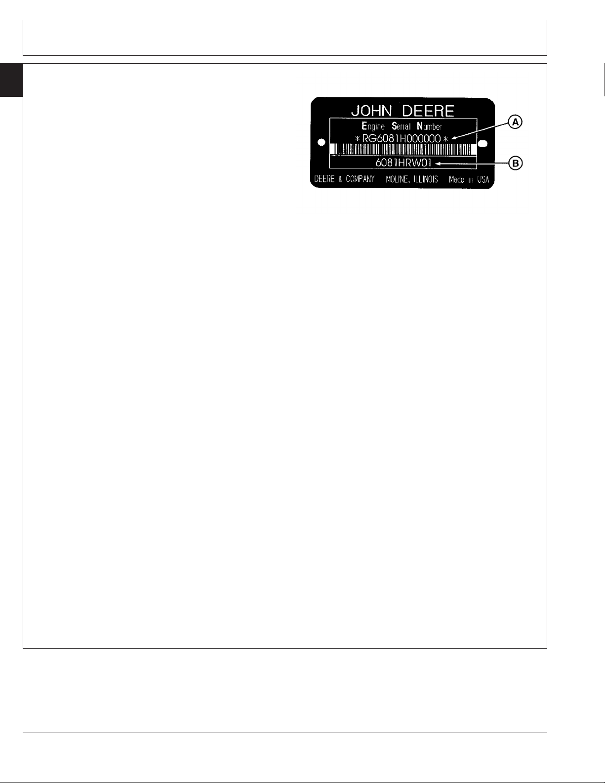
Engine Serial Number (A)
Each engine has a 13-digit John Deere engine serial
number identifying the producing factory, engine model
designation, and a 6-digit sequential number. The
following is an example:
Engine Identification
RG7010 –UN–26NOV97
Engine Serial Number Plate
RG6081H000000
RG ........................................................ Factory code producing engine
6081H ........................................................... Engine model designation
000000 .......................................................... Sequential serial number
Factory Code
RG ............................................................... Waterloo Engine Works
Engine Model Designation
6801H .................................... (See ENGINE MODEL DESIGNATION.)
Sequential Number
000000 .......................................................... 6-digit sequential number
The engine serial number plate is located either on the
right-hand side of engine between the oil filter base and
fuel injection pump (viewed from flywheel end) or on the
left-hand side of the engine directly above the starter
motor.
Engine Application Data (B)
The second line of information on the engine serial
number plate identifies the engine/Deere machine or OEM
relationship. SeeENGINE APPLICATION CHART later in
this group.
A—Engine Serial Number
B—Engine Application Data
CTM86 (20MAR01)
01-001-2
P
OWERTECH
RG,RG34710,1022 –19–19MAY99–1/1
8.1 L Diesel Engines — Base Engine
PN=24
032001
Page 25
Engine Option Code Label
Engine Identification
01
001
3
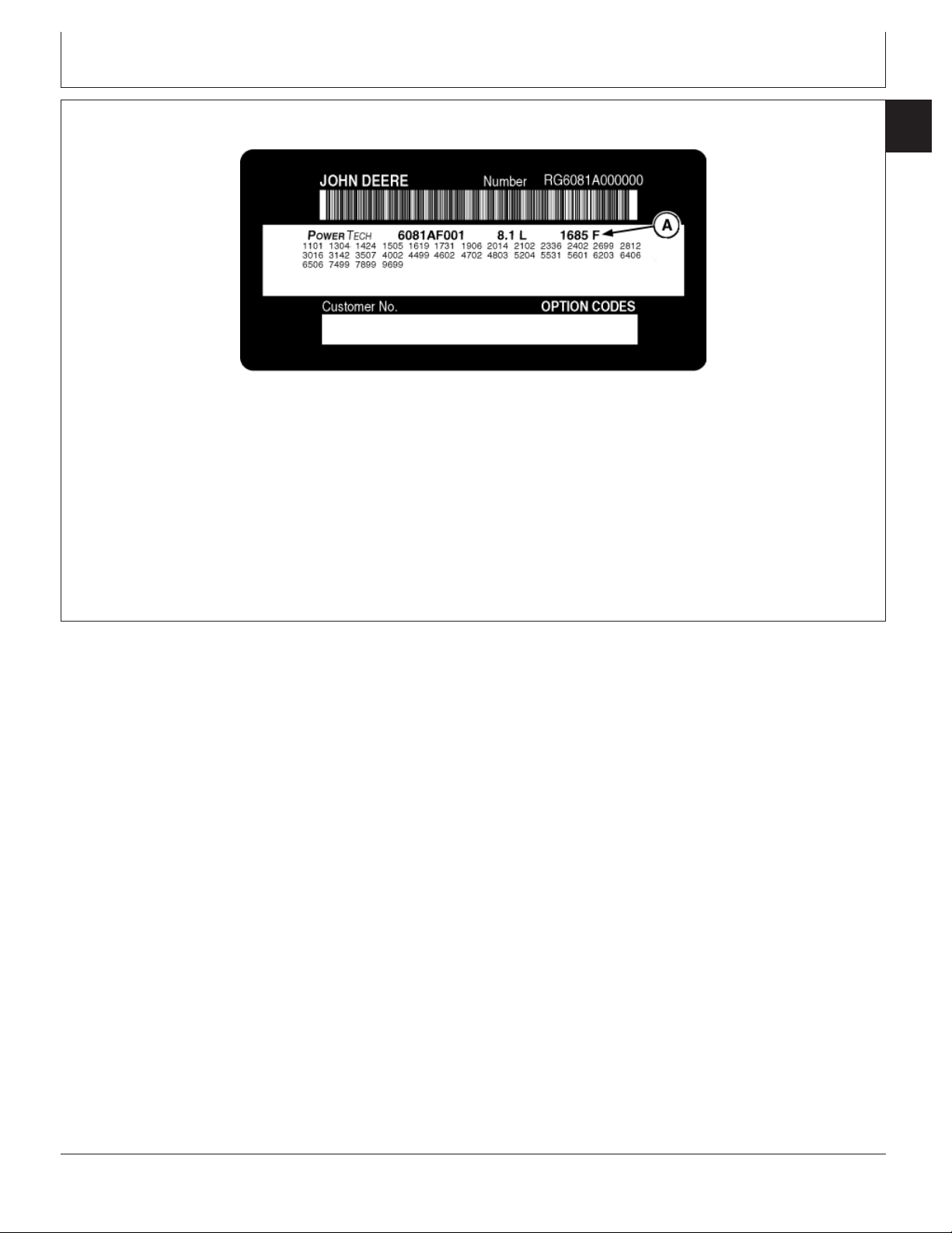
Option Code Label
In addition to the serial number plate, later OEM
engines have an engine option code label affixed to
the rocker arm cover. These codes indicate which of
the engine options were installed on your engine at the
RG11074 –UN–14AUG00
factory. When in need of parts or service, furnish your
authorized servicing dealer or engine distributor with
these numbers.
DPSG,OUO1004,900 –19–19MAY99–1/1
CTM86 (20MAR01)
01-001-3
P
OWERTECH
8.1 L Diesel Engines — Base Engine
PN=25
032001
Page 26

01
001
Engine Application Chart (John Deere
4
Agricultural Equipment)
Machine Model Engine Model
DES MOINES—COTTON PICKERS
9970 Cotton Picker ............................................................. 6081AN001
9976 Cotton Picker .................................................... 6081HN001, 003
HARVESTER—COMBINES
9510 Low Power Combine ................................................. 6081HH001
9510 High Power Combine ................................................ 6081HH002
9550 Low Power Combine ................................................. 6081HH008
9550 High Power Combine ................................................ 6081HH009
9610 Combine .................................................................... 6081HH003
9650 and 9650CTS Combine ............................................ 6081HH010
9650 CTS-(Europe) Combine ............................................ 6081HH011
9650 STS Combine ............................................................ 6081HH006
9750 STS Combine ............................................................ 6081HH005
CTS II Combine (Europe-1998 Model Year ...................... 6081HH003
CTS II Combine (Europe-1999 Model Year) ..................... 6081HH004
CTS II Combine (North America) ....................................... 6081HH003
Amadus Peanut Combine .................................................. 6081HH007
WATERLOO—TRACTORS
7710 Tractor .............................................. 6081TRW01, 03, 05, 07, 09
7810 Tractor ....................................... 6081TRW02, 04, 06, 08, 10, 11
8100 Tractor ...................................................................... 6081HRW06
8200 Tractor ...................................................................... 6081HRW07
8300 Tractor ...................................................................... 6081HRW08
8400 Tractor ................................................................ 6081HRW01, 04
8100T (Tracks) Tractor ..................................................... 6081HRW10
8200T (Tracks) Tractor ..................................................... 6081HRW02
8300T (Tracks) Tractor ..................................................... 6081HRW09
8400T (Tracks) Tractor ..................................................... 6081HRW03
8110 Tractor ...................................................................... 6081HRW11
8210 Tractor ...................................................................... 6081HRW13
8310 Tractor ...................................................................... 6081HRW15
8410 Tractor ...................................................................... 6081HRW17
8110T (Tracks) Tractor ..................................................... 6081HRW12
8210T (Tracks) Tractor ..................................................... 6081HRW14
8310T (Tracks) Tractor ..................................................... 6081HRW16
8410T (Tracks) Tractor ..................................................... 6081HRW18
9100 4-Wheel Drive Tractor .............................................. 6081HRW05
ZWEIBRUCKEN—COMBINES/FORAGE HARVESTERS
2256 Combine ............................................................. 6081HZ003, 007
2258 Combine ............................................................... 6081HZ002, 05
2264 Combine ..................................................................... 6081HZ002
2266 Combine ..................................................................... 6081HZ001
2268 Combine ..................................................................... 6081HZ006
6650 Self-Propelled Forage Harvester ............................... 6081HZ004
S.L.C. HORIZONTINA (BRAZIL)—COMBINES
1185A Combine ................................................................. 6081ACQ01
Engine Identification
CTM86 (20MAR01)
01-001-4
P
OWERTECH
RG,RG34710,1023 –19–23OCT97–1/1
8.1 L Diesel Engines — Base Engine
PN=26
032001
Page 27

Engine Identification
Engine Application Chart (John Deere Construction Equipment)
Machine Model Engine Model
DAVENPORT
644G Loader ..................................................................... 6081HDW04
644H Loader ..................................................................... 6081HDW05
644H-MH Loader ............................................................... 6081HDW06
740G/748G/748G II/748G III Skidder ............................... 6081TDW01
770C (Late)/770CH/772CH Motor Grader ........................ 6081HDW01
770C Motor Grader (Early) ............................................... 6081HDW03
DUBUQUE
762B Series II Scraper ........................................................ 6081AT001
850C Series II Crawler Dozer (822868— ) ........................ 6081AT002
KERNERSVILLE (DEERE-HITACHI)
330LC/370 Excavator .......................................................... 6081HT001
BESSEMER
530B/535 Log Loader ......................................................... 6081ATJ01
WOODSTOCK, ON
660D Skidder ...................................................................... 6081ATJ02
01
001
5
Engine Application Chart (OEM) (Outside Equipment Manufacturers)
Application Engine Model
OEM Engine (Tier I Emissions Certified) ........................ 6081TF001
OEM Engine (Tier I Emissions Certified) ............................ 6081AF001
OEM Engine (Tier I Emissions Certified) ............................ 6081HF001
Marine Engine .................................................................... 6081AFM01
OEM Engine (Tier II Emissions Certified) ........................... 6081HF070
RG41183,0000024 –19–25JAN01–1/1
RG41183,000003A –19–28FEB01–1/1
CTM86 (20MAR01)
01-001-5
P
OWERTECH
8.1 L Diesel Engines — Base Engine
PN=27
032001
Page 28

01
001
Engine Identification
6
CTM86 (20MAR01)
01-001-6
P
OWERTECH
8.1 L Diesel Engines — Base Engine
PN=28
032001
Page 29

Diesel Fuel
Consult your local fuel distributor for properties of the
diesel fuel available in your area.
Group 002
Fuels, Lubricants and Coolant
01
002
1
Fuel lubricity should pass a minimum of 3100 gram
load level as measured by the BOCLE scuffing test.
In general, diesel fuels are blended to satisfy the low
temperature requirements of the geographical area in
which they are marketed.
Diesel fuels specified to EN 590 or ASTM D975 are
recommended.
In all cases, the fuel shall meet the following
properties:
Cetane number of 40 minimum. Cetane number
greater than 50 is preferred, especially for
temperatures below -20°C (-4°F) or elevations above
1500 m (5000 ft).
Cold Filter Plugging Point (CFPP) below the
expected low temperature OR Cloud Point at least
5°C(9°F) below the expected low temperature.
Sulfur content:
• Sulfur content should not exceed 0.5%. Sulfur
content less than 0.05% is preferred.
• If diesel fuel with sulfur content greater than 0.5%
sulfur content is used, reduce the service interval for
engine oil and filter by 50%.
• DO NOT use diesel fuel with sulfur content greater
than 1.0%.
DO NOT mix used engine oil or any other type of
lubricant with diesel fuel.
RG41165,0000071 –19–13MAR01–1/1
CTM86 (20MAR01)
01-002-1
P
OWERTECH
8.1 L Diesel Engines — Base Engine
PN=29
032001
Page 30

Fuels, Lubricants and Coolant
01
002
Bio-Diesel Fuel
2
Bio-diesel fuels may be used ONLY if the fuel
properties meet DIN 51606 or equivalent specification.
It has been shown that bio-diesel fuels have been
found to improve lubricity in concentrations up to 5%
blend in petroleum diesel fuel.
When using a blend of bio-diesel fuel with fuel pumps,
the oil level MUST be checked daily when the air
temperature is -10° C (14° F) or lower. If oil becomes
diluted with fuel, oil change intervals must be
shortened accordingly.
IMPORTANT: Raw pressed vegetable oils are NOT
acceptable for use for fuel in any
concentration in John Deere
engines. These oils do not burn
completely, and will cause engine
failure by leaving deposits on
injectors and in the combustion
chamber.
Users of bio-diesel fuel should always remember that a
major selling merit is its ability to biodegrade, so the
storage and handling of this fuel is very important. This
importance can be seen in the following areas of
concern:
• The quality of the fresh fuel,
• Water content of the fuel,
• Problems due to aging of the fuel.
Potential problems resulting from deficiencies in the
above areas when using bio-diesel fuel in
concentrations above 5% may lead to the following
symptoms:
• Power loss and deterioration of performance,
• Fuel leakage,
• Corrosion of fuel injection equipment,
• Coked/blocked injector nozzles, leading to poor
atomization of fuel,
• Filter plugging,
• Lacquering/seizure of internal components,
• Sludge and sediments,
• Reduced service life.
CTM86 (20MAR01)
Continued on next page
01-002-2
P
OWERTECH
RG41165,0000034 –19–13MAR01–1/2
8.1 L Diesel Engines — Base Engine
PN=30
032001
Page 31

Fuels, Lubricants and Coolant
Bio-Diesel Property List for DIN 51606
Property Unit DIN 51606 Sept 1997
Density at 15° C(59° F) g/cm3(lb/ft3) 0.875—0.900 (55—56)
Viscosity at 40° C(104° F) mm2/s (cST) 3.5—5.0
Flash Point °C(°F) Min. 110 (230)
Cold Filter Plugging Point—Summer °C(°F) Max. 0 (32)
Cold Filter Plugging Point—Winter °C(°F) Max. -20 (-4)
Total Sulfur % Mass 0.01
Conradson (CCR) at 100% % Mass Max. 0.05
Cetane Number — Min. 49
Ash Content % Mass Max. 0.03
Water Content % Mass Max. 0.03
Total Contamination % Mass Max. 0.002
Copper Corrosion (3 hours, 50° C) (3 hours, Degree of Corrosion 1
122° F)
Neutralization Value mg KOH/g Max. 0.5
Methanol Content % Mass Max. 0.3
Monoglycerides % Mass Max. 0.8
Diglycerides % Mass Max. 0.4
Trigycerides % Mass Max. 0.4
Free Glycerine % Mass Max. 0.02
Total Glycerine % Mass Max. 0.25
Iodine Number — Max. 115
Phosphorus % Mass Max. 0.001
Alkali Content (Na + K) % Mass Max. 0.0005
01
002
3
CTM86 (20MAR01)
01-002-3
P
OWERTECH
RG41165,0000034 –19–13MAR01–2/2
8.1 L Diesel Engines — Base Engine
PN=31
032001
Page 32

Fuels, Lubricants and Coolant
01
002
Lubricity of Diesel Fuel
4
Diesel fuel must have adequate lubricity to ensure
proper operation and durability of fuel injection system
components.
Diesel fuels for highway use in the United States and
Canada require sulfur content less than 0.05%.
Diesel fuel in the European Union requires sulfur
content less than 0.05%.
Experience shows that some low sulfur diesel fuels
may have inadequate lubricity and their use may
reduce performance in fuel injection systems due to
inadequate lubrication of injection pump components.
The lower concentration of aromatic compounds in
these fuels also adversely affects injection pump seals
and may result in leaks.
Use of low lubricity diesel fuels may also cause
accelerated wear, injection nozzle erosion or corrosion,
engine speed instability, hard starting, low power, and
engine smoke.
Fuel lubricity should pass a minimum of 3100 gram
load level as measured by the BOCLE scuffing test.
ASTM D975 and EN 590 specifications do not require
fuels to pass a fuel lubricity test.
If fuel of low or unknown lubricity is used, add John
Deere PREMIUM DIESEL FUEL CONDITIONER (or
equivalent) at the specified concentration.
Dieselscan Fuel Analysis
DIESELSCAN is a John Deere fuel sampling program to
help you monitor the quality of your fuel source. It verifies
fuel type, cleanliness, water content, suitability for cold
weather operation, and if fuel is within ASTM
specifications. Check with your John Deere dealer for
availability of DIESELSCAN kits.
DIESELSCAN is a trademark of Deere & Company
DX,FUEL5 –19–24JAN00–1/1
DX,FUEL6 –19–06DEC00–1/1
CTM86 (20MAR01)
01-002-4
P
OWERTECH
8.1 L Diesel Engines — Base Engine
PN=32
032001
Page 33

Fuels, Lubricants and Coolant
Diesel Engine Break-In Oil
New engines are filled at the factory with John Deere
ENGINE BREAK-IN OIL. During the break-in period,
add John Deere ENGINE BREAK-IN OIL as needed to
maintain the specified oil level.
Change the oil and filter after the first 100 hours of
operation of a new or rebuilt engine.
After engine overhaul, fill the engine with John Deere
ENGINE BREAK-IN OIL.
If John Deere ENGINE BREAK-IN OIL is not available,
use a diesel engine oil meeting one of the following
during the first 100 hours of operation:
• API Service Classification CE
01
002
5
• ACEA Specification E1
After the break-in period, use John Deere PLUS-50or
other diesel engine oil as recommended in this
manual.
IMPORTANT: Do not use PLUS-50 oil or engine
oils meeting API CH-4, API CG4, API
CF4, ACEA E3, or ACEA E2
performance levels during the first
100 hours of operation of a new or
rebuilt engine. These oils will not
allow the engine to break-in
properly.
PLUS-50 is a registered trademark of Deere & Company.
DX,ENOIL4 –19–24JAN00–1/1
CTM86 (20MAR01)
01-002-5
P
OWERTECH
8.1 L Diesel Engines — Base Engine
PN=33
032001
Page 34

Fuels, Lubricants and Coolant
01
002
Diesel Engine Oil
6
Use oil viscosity based on the expected air temperature
range during the period between oil changes.
The following oil is preferred:
• John Deere PLUS-50
The following oil is also recommended:
• John Deere TORQ-GARD SUPREME
Other oils may be used if they meet one or more of the
following:
• API Service Classification CH-4
• API Service Classification CG-4
• API Service Classification CF-4
• ACEA Specification E3
• ACEA Specification E2
Multi-viscosity diesel engine oils are preferred.
If diesel fuel with sulfur content greater than 0.5% is used,
reduce the service interval by 50%.
Extended service intervals may apply when John Deere
preferred engine oils are used. Consult your John Deere
dealer for more information.
TS1661 –UN–10OCT97
PLUS-50 is a registered trademark of Deere & Company.
TORQ-GARD SUPREME is a registered trademark of Deere & Company
Extended Diesel Engine Oil Service Intervals
When John Deere PLUS-50oil and the specified John
Deere filter are used, the service interval for engine oil
and filter changes may be increased by 50%.
If other than PLUS-50oil and the specified John Deere
filter are used, change the engine oil and filter at the
normal service interval.
PLUS-50 is a trademark of Deere & Company
CTM86 (20MAR01)
01-002-6
P
OWERTECH
DX,ENOIL –19–24JAN00–1/1
DX,ENOIL6 –19–10OCT97–1/1
8.1 L Diesel Engines — Base Engine
PN=34
032001
Page 35

Fuels, Lubricants and Coolant
Alternative and Synthetic Lubricants
Conditions in certain geographical areas may require
lubricant recommendations different from those printed in
this manual.
Some John Deere brand coolants and lubricants may not
be available in your location.
Consult your John Deere dealer to obtain information and
recommendations.
Synthetic lubricants may be used if they meet the
performance requirements as shown in this manual.
The temperature limits and service intervals shown in this
manual apply to both conventional and synthetic oils.
Re-refined base stock products may be used if the
finished lubricant meets the performance requirements.
01
002
7
Mixing of Lubricants
In general, avoid mixing different brands or types of oil.
Oil manufacturers blend additives in their oils to meet
certain specifications and performance requirements.
Mixing different oils can interfere with the proper
functioning of these additives and degrade lubricant
performance.
DX,ALTER –19–15JUN00–1/1
Consult your John Deere dealer to obtain specific
information and recommendations.
DX,LUBMIX –19–18MAR96–1/1
CTM86 (20MAR01)
01-002-7
P
OWERTECH
8.1 L Diesel Engines — Base Engine
PN=35
032001
Page 36

Fuels, Lubricants and Coolant
01
002
OILSCANand CoolScan
8
OILSCANand CoolScanare John Deere sampling
programs to help you monitor machine performance and
identify potential problems before they cause serious
damage.
Oil and coolant samples should be taken from each
system prior to its recommended change interval.
Check with your John Deere dealer for the availability of
OILSCANand CoolScankits.
T6828AB –UN–15JUN89T6829AB –UN–18OCT88
OILSCAN is a registered trademark of Deere & Company.
CoolScan is a registered trademark of Deere & Company.
DPSG,OUOD002,1824 –19–02AUG00–1/1
CTM86 (20MAR01)
01-002-8
P
OWERTECH
8.1 L Diesel Engines — Base Engine
PN=36
032001
Page 37

Fuels, Lubricants and Coolant
Grease
Use grease based on NLGI consistency numbers and the
expected air temperature range during the service interval.
The following greases are preferred:
• John Deere SD POLYUREA GREASE
The following greases are also recommended:
• John Deere HD MOLY GREASE
• John Deere HD LITHIUM COMPLEX GREASE
• John Deere HD WATER RESISTANT GREASE
• John Deere GREASE-GARD
Other greases may be used if they meet the following:
• NLGI Performance Classification GC-LB
IMPORTANT: Some types of grease thickener are not
compatible with others. Consult your
grease supplier before mixing different
types of grease.
01
002
9
TS1667 –UN–30JUN99
CTM86 (20MAR01)
01-002-9
P
OWERTECH
DX,GREA1 –19–24JAN00–1/1
8.1 L Diesel Engines — Base Engine
PN=37
032001
Page 38

01
002
Diesel Engine Coolant
10
The engine cooling system is filled to provide
year-round protection against corrosion and cylinder
liner pitting, and winter freeze protection to -37°C
(-34°F).
The following engine coolant is preferred for service:
• John Deere COOL-GARD Prediluted Coolant
The following engine coolant is also recommended:
• John Deere COOL-GARD Coolant Concentrate in a
40 to 60% mixture of concentrate with quality water.
Fuels, Lubricants and Coolant
protection at lower temperatures is required, consult
your John Deere dealer for recommendations.
Water quality is important to the performance of the
cooling system. Distilled, deionized, or demineralized
water is recommended for mixing with ethylene glycol
base engine coolant concentrate.
IMPORTANT: Do not use cooling system sealing
additives or antifreeze that contains
sealing additives.
Coolant Drain Intervals
Other low silicate ethylene glycol base coolants for
heavy-duty engines may be used if they meet one of
the following specifications:
• ASTM D5345 (prediluted coolant)
• ASTM D4985 (coolant concentrate) in a 40 to 60%
mixture of concentrate with quality water
Coolants meeting these specifications require use of
supplemental coolant additives, formulated for
heavy-duty diesel engines, for protection against
corrosion and cylinder liner erosion and pitting.
A 50% mixture of ethylene glycol engine coolant in
water provides freeze protection to -37°C (-34°F). If
Drain the factory fill engine coolant, flush the cooling
system, and refill with new coolant after the first 3
years or 3000 hours of operation. Subsequent drain
intervals are determined by the coolant used for
service. At each interval, drain the coolant, flush the
cooling system, and refill with new coolant.
When John Deere COOL-GARD is used, the drain
interval may be extended to 5 years or 5000 hours of
operation, provided that the coolant is tested annually
AND additives are replenished, as needed, by adding
a supplemental coolant additive.
If COOL-GARD is not used, the drain interval is
reduced to 2 years or 2000 hours of operation.
CTM86 (20MAR01)
01-002-10
P
OWERTECH
DX,COOL3 –19–05FEB99–1/1
8.1 L Diesel Engines — Base Engine
PN=38
032001
Page 39

Fuels, Lubricants and Coolant
Diesel Engine Coolants, Supplemental Additive Information
Engine coolants are a combination of three chemical
components: ethylene glycol (antifreeze), inhibiting
coolant additives, and quality water.
Coolant Specifications
Some products, including John Deere COOL-GARD
Prediluted Coolant, are fully formulated coolants that
contain all three components in their correct
concentrations. Do not add an initial charge of
supplemental coolant additives to these fully
formulated products.
Some coolant concentrates, including John Deere
COOL-GARD Coolant Concentrate, contain both
ethylene glycol antifreeze and inhibiting coolant
additives. Mix these products and quality water, but do
not add an initial charge of supplemental coolant
additives.
Coolants meeting ASTM D5345 (prediluted coolant) or
ASTM D4985 (coolant concentrate) require an initial
charge of supplemental coolant additives.
Replenish Coolant Additives
The concentration of coolant additives is gradually
depleted during engine operation. Periodic
replenishment of inhibitors is required, even when
John Deere COOL-GARD is used. Follow the
recommendations in this manual for the use of
supplemental coolant additives.
Why Use Supplemental Coolant Additives?
Operating without proper coolant additives will result in
increased corrosion, cylinder liner erosion and pitting,
and other damage to the engine and cooling system. A
simple mixture of ethylene glycol and water will not
give adequate protection.
This film acts as a barrier against the harmful effects
of collapsing vapor bubbles.
Avoid Automotive-Type Coolants
Never use automotive-type coolants (such as those
meeting ASTM D3306 or ASTM D4656). These
coolants do not contain the correct additives to protect
heavy-duty diesel engines. They often contain a high
concentration of silicates and may damage the engine
or cooling system.
Non-Aqueous Propylene Glycol
Non-aqueous propylene glycol should not be used with
John Deere diesel engines. This coolant works best
with coolant temperatures above the acceptable
engine operating range. This could decrease engine
life due to lower engine oil viscosity. In addition,
electronically controlled engines could experience
premature power de-rate due to high coolant
temperature.
Water Quality
Water quality is important to the performance of the
cooling system. Distilled, deionized, or demineralized
water is recommended for mixing with ethylene glycol
base engine coolant concentrate. All water used in the
cooling system should meet the following minimum
specifications for quality:
Chlorides 40 mg/L or less
Sulfates 100 mg/L or less
Total Dissolved Solids 340 mg/L or less
Total Hardness 170 mg/L or less
pH Level 5.5 to 9.0
Freeze Protection
01
002
11
Use of supplemental coolant additives reduces
corrosion, erosion, and pitting. These chemicals
reduce the number of vapor bubbles in the coolant and
help form a protective film on cylinder liner surfaces.
CTM86 (20MAR01)
The relative concentrations of ethylene glycol and
water in the engine coolant determine its freeze
protection limit. Refer to the chart on the following
page.
Continued on next page
01-002-11
P
OWERTECH
DPSG,OUOD002,1835 –19–03AUG00–1/2
8.1 L Diesel Engines — Base Engine
PN=39
032001
Page 40

Fuels, Lubricants and Coolant
01
002
12
Ethylene Glycol Freeze Protection Limit
40% -24°C (-12°F)
50% -37°C (-34°F)
60% -52°C (-62°F)
Testing Diesel Engine Coolant
Maintaining adequate concentrations of glycol and
inhibiting additives in the coolant is critical to protect the
engine and cooling system against freezing, corrosion,
and cylinder liner erosion and pitting.
Test the coolant solution at intervals of 12 months or less
and whenever excessive coolant is lost through leaks or
overheating.
Coolant Test Strips
Coolant test strips are available from your John Deere
dealer. These test strips provide a simple, effective
method to check the freeze point and additive levels of
your engine coolant.
DO NOT use a coolant-water mixture greater than
60% ethylene glycol.
DPSG,OUOD002,1835 –19–03AUG00–2/2
Compare the results to the supplemental coolant additive
(SCA) chart to determine the amount of inhibiting
additives in your coolant and whether more John Deere
COOLANT CONDITIONER should be added.
CoolScan
For a more thorough evaluation of your coolant, perform a
CoolScan analysis. See your John Deere dealer for
information about CoolScan.
DPSG,OUOD002,1825 –19–02AUG00–1/1
CTM86 (20MAR01)
01-002-12
P
OWERTECH
8.1 L Diesel Engines — Base Engine
PN=40
032001
Page 41

Fuels, Lubricants and Coolant
Replenishing Supplemental Coolant Additives (SCAs) Between Coolant Changes
01
002
13
IMPORTANT: Do not add supplemental coolant
additives when the cooling system is
drained and refilled with John Deere
ANTIFREEZE/SUMMER COOLANT or
John Deere COOL-GARD.
NOTE: If a system is to be filled with coolant that does
not contain SCAs, the coolant must be
precharged. Determine the total system
capacity and premix with 3% John Deere
Coolant Conditioner.
Through time and use, the concentration of coolant
additives is gradually depleted during engine operation.
Periodic replenishment of inhibitors is required, even
when John Deere ANTIFREEZE/SUMMER COOLANT
is used. The cooling system must be recharged with
additional supplemental coolant additives available in
the form of liquid coolant conditioner.
RG6261 –UN–08DEC97
Maintaining the correct coolant conditioner
concentration (SCAs) and freeze point is essential in
your cooling system to protect against rust, liner pitting
and corrosion, and freeze-ups due to incorrect coolant
dilution.
John Deere LIQUID COOLANT CONDITIONER is
recommended as a supplemental coolant additive
in John Deere engines.
DO NOT mix one brand of SCA with a different
brand.
Test the coolant solution at 600 hours or 12 months of
operation using either John Deere coolant test strips or
a COOLSCANanalysis. If a COOLSCANanalysis is
not available, recharge system per instructions printed
on label of John Deere Liquid Coolant Conditioner.
RG6262 –UN–05DEC97
COOL-GARD is a registered trademark of Deere & Company
COOLSCAN is a registered trademark of Deere & Company.
CTM86 (20MAR01)
Continued on next page
01-002-13
P
OWERTECH
RG,01,DT7035 –19–14NOV00–1/2
8.1 L Diesel Engines — Base Engine
PN=41
032001
Page 42

Fuels, Lubricants and Coolant
01
002
IMPORTANT: ALWAYS maintain coolant at correct
14
level and concentration. DO NOT
operate engine without coolant for
even a few minutes.
If frequent coolant makeup is
required, the glycol concentration
should be checked with JT07298
Coolant/Battery Tester to ensure that
the desired freeze point is
maintained. Follow manufacturer’s
instructions provided with
Coolant/Battery Tester.
Add the manufacturer’s recommended concentration of
supplemental coolant additive. DO NOT add more than
the recommended amount.
The use of non-recommended supplemental coolant
additives may result in additive drop-out and gelation
of the coolant.
If other coolants are used, consult the coolant supplier
and follow the manufacturer’s recommendation for use
of supplemental coolant additives.
See DIESEL ENGINE COOLANTS, SUPPLEMENTAL
ADDITIVE INFORMATION earlier in this group for
proper mixing of coolant ingredients before adding to
the cooling system.
Operating in Warm Temperature Climates
John Deere engines are designed to operate using glycol
base engine coolants.
Always use a recommended glycol base engine coolant,
even when operating in geographical areas where freeze
protection is not required.
IMPORTANT: Water may be used as coolant
emergency situations only.
Foaming, hot surface aluminum and
iron corrosion, scaling, and cavitation
will occur when water is used as the
coolant, even when coolant
conditioners are added.
Drain cooling system and refill with
recommended glycol base engine
coolant as soon as possible.
in
RG,01,DT7035 –19–14NOV00–2/2
CTM86 (20MAR01)
01-002-14
P
OWERTECH
DX,COOL6 –19–18MAR96–1/1
8.1 L Diesel Engines — Base Engine
PN=42
032001
Page 43

Fuels, Lubricants and Coolant
Flush and Service Cooling System
CAUTION: Explosive release of fluids from
pressurized cooling system can cause serious
burns. Shut off engine. Only remove filler cap
when cool enough to touch with bare hands.
Slowly loosen cap to first stop to relieve
pressure before removing cap completely.
IMPORTANT: Air must be expelled from cooling
system when system is refilled. See
CHECKING COOLING SYSTEM in
operator’s manual.
The ethylene glycol base (antifreeze) can become
depleted of SCAs allowing various acids to form that will
damage engine components. In addition, heavy metals,
such as lead, copper and zinc, accumulate in the ethylene
glycol base. The heavy metals come from corrosion that
occurs to some degree with in a cooling system. When a
coolant is saturated to the point where it can no longer
hold heavy metals and other dissolved solids, they settle
out and act as abrasives on engine parts.
01
002
15
TS281 –UN–23AUG88
NOTE: Refer to your operator’s manual for a specific
service interval. See LUBRICATION AND
MAINTENANCE SERVICE INTERVAL CHART in
operator’s manual.
Flush cooling system as described in your operator’s
manual. See FLUSHING COOLING SYSTEM in
operator’s manual. Clean cooling system with clean water
and TY15979 John Deere Heavy-Duty Cooling System
Cleaner or an equivalent cleaner such as FLEETGUARD
RESTOREor RESTORE PLUS. Follow the instructions
provided with the cleaner. Refill cooling system with the
appropriate coolant solution. See DIESEL ENGINE
COOLANT, earlier in this group.
FLEETGUARD is a registered trademark of the Cummins Engine
Company.
RESTORE is a trademark of FLEETGUARD.
RESTORE PLUS is a trademark of FLEETGUARD.
CTM86 (20MAR01)
Continued on next page
01-002-15
P
OWERTECH
RG,01,DT7033 –19–29OCT97–1/2
8.1 L Diesel Engines — Base Engine
PN=43
032001
Page 44

Fuels, Lubricants and Coolant
01
002
IMPORTANT: NEVER overfill the system. A
16
pressurized system needs space for
heat expansion without overflowing at
the top of the radiator. Coolant level
should be at bottom of radiator filler
neck.
Air must be expelled from cooling
system when system is refilled. Loosen
plug in side of thermostat housing to
allow air to escape when filling system.
Retighten plug when all the air has
been expelled.
After adding new coolant solution, run engine until it
reaches operating temperature. This mixes the coolant
solution uniformly and circulates it through the entire
system. After running engine, check coolant level and
entire cooling system for leaks.
Contact your engine servicing dealer, if there are further
questions.
Disposing of Coolant
Improperly disposing of engine coolant can threaten the
environment and ecology.
Use leakproof containers when draining fluids. Do not use
food or beverage containers that may mislead someone
into drinking from them.
Do not pour waste onto the ground, down a drain, or into
any water source.
Inquire on the proper way to recycle or dispose of waste
from your local environmental or recycling center, or from
your engine servicing dealer.
RG,01,DT7033 –19–29OCT97–2/2
TS1133 –UN–26NOV90
RG,01,DT7032 –19–29OCT97–1/1
CTM86 (20MAR01)
01-002-16
P
OWERTECH
8.1 L Diesel Engines — Base Engine
PN=44
032001
Page 45

Section 02
Repair and Adjustments
Contents
Page Page
Group 010—Engine Rebuild
Engine Overhaul Guidelines ..............02-010-1
Engine Repair Stand....................02-010-1
Safety Precautions .....................02-010-2
Install Adapters on Engine Repair Stand.....02-010-2
Engine Lifting Procedure.................02-010-3
Clean Engine .........................02-010-4
Disconnect Turbocharger Oil Inlet Line ......02-010-5
Mount Engine on Repair Stand ............02-010-6
Engine Disassembly Sequence for
Overhaul ...........................02-010-8
Sealant Application Guidelines ............02-010-9
6081 Engine Assembly Sequence After
Overhaul ..........................02-010-11
Engine Break-In Guidelines..............02-010-13
Perform Engine Break-In................02-010-14
Check Crankcase Ventilation System ......02-010-16
Check Air Intake System................02-010-16
Check Exhaust System.................02-010-17
Check and Service Cooling System .......02-010-17
Check Electrical System ................02-010-19
General Tune-Up Recommendations ......02-010-21
Group 020—Cylinder Head and Valves Repair and
Adjustment S. N. ( —199,999)
Check and Adjust Valve Clearance Serial
Number ( —199,999)..................02-020-1
Check Valve Lift Serial Number
( —199,999) ........................02-020-5
Remove Cylinder Head Serial Number
( —199,999) ........................02-020-6
Head Gasket Inspection and Repair
Sequence Serial Number ( —199,999) ....02-020-9
Disassemble and Inspect Rocker Arm Shaft
Assembly Serial Number
( —199,999) .......................02-020-11
Assemble Rocker Arm Shaft Assembly
Serial Number ( —199,999)............02-020-12
Measure Valve Recess Serial Number
( —199,999) .......................02-020-13
Preliminary Cylinder Head and Valve
Checks Serial Number ( —199,999) .....02-020-14
Remove Valve Assembly Serial Number
( —199,999) .......................02-020-15 ( —199,999) .......................02-020-32
Inspect and Measure Valve Springs Serial
Number ( —199,999).................02-020-16
CTM86 (20MAR01)
Inspect Valve Spring Caps, Wear Caps, and
Retainer Locks Serial Number
( —199,999) .......................02-020-17
Clean Valves Serial Number ( —199,999). . .02-020-17
Inspect and Measure Valves Serial Number
( —199,999) .......................02-020-18
Grind (Reface) Valves Serial Number
( —199,999) .......................02-020-19
Inspect and Clean Cylinder Head Serial
Number ( —199,999).................02-020-19
Check Cylinder Head Combustion Face
Flatness Serial Number ( —199,999).....02-020-20
Measure Cylinder Head Thickness Serial
Number ( —199,999).................02-020-21
Clean Valve Guides Serial Number
( —199,999) .......................02-020-22
Measure Valve Guides Serial Number
( —199,999) .......................02-020-22
Knurl Valve Guides Serial Number
( —199,999) .......................02-020-23
Clean and Inspect Valve Seats Serial
Number ( —199,999).................02-020-23
Measure Valve Sears Serial Number
( —199,999) .......................02-020-24
Grind Valve Seats Serial Number
( —199,999) .......................02-020-25
Remove Valve Seat Inserts Serial Number
( —199,999) .......................02-020-26
Install Valve Seat Inserts Serial Number
( —199,999) .......................02-020-27
Inspect and Clean Cylinder Head Nozzle
Bore Serial Number ( —199,999)........02-020-27
Clean and Inspect Push Rods Serial Number
( —199,999) .......................02-020-29
Inspect and Clean Ventilator Outlet Hose
Serial Number ( —199,999)............02-020-29
Clean and Inspect Top Deck of Cylinder
Block Serial Number ( —199,999) .......02-020-30
Measure Cylinder Liner Standout (Height
Above Block) Serial Number
( —199,999) .......................02-020-31
Assemble Valve Assembly Serial Number
Continued on next page
02-1
P
OWERTECH
8.1 L Diesel Engines — Base Engine
02
032001
PN=1
Page 46

Contents
Page Page
Install Cylinder Head and Cap Screws Grind (Reface) Valves Serial Number
Serial Number ( —199,999)............02-020-33
Torque-to-Yield Flanged-Head Cap Screws—
02
Grade 180 Marked “SPECIAL” Serial
Number ( —199,999).................02-020-35
Install Rocker Arm Assembly Serial Number
( —199,999) .......................02-020-36
Inspect and Clean Ventilator Outlet Hose
Serial Number ( —199,999)............02-020-37
Complete Final Assembly of Injection Pump
Side of Engine Serial Number
( —199,999) .......................02-020-38
Complete Final Assembly on Exhaust
Manifold Side of Engine Serial Number
( —199,999) .......................02-020-39
Perform Engine Break-In Serial Number
( —199,999) .......................02-020-40
(200,000— ) .......................02-021-22
Inspect and Clean Cylinder Head Serial
Number (200,000— ).................02-021-23
Check Cylinder Head Combustion Face
Flatness Serial Number (200,000— ).....02-021-24
Measure Cylinder Head Thickness Serial
Number (200,000— ).................02-021-25
Clean Valve Guides Serial Number
(200,000— ) .......................02-021-26
Measure Valve Guides Serial Number
(200,000— ) .......................02-021-26
Knurl Valve Guides Serial Number
(200,000— ) .......................02-021-27
Clean and Inspect Valve Seats Serial
Number (200,000— ).................02-021-27
Measure Valve Seats Serial Number
(200,000— ) .......................02-021-28
Group 021—Cylinder Head and Valves Repair and
Adjustment S. N. (200,000— )
Check Valve Clearance Serial Number
(200,000— ) ........................02-021-1
Adjust Valve Clearance Serial Number
(200,000— ) ........................02-021-4
Check Valve Lift Serial Number
(200,000— ) ........................02-021-8
Remove Cylinder Head Serial Number
(200,000— ) ........................02-021-9
Diagnosing Head Gasket Joint Failures
Serial Number (200,000— )............02-021-11
Head Gasket Diagnostic Charts Serial
Number (200,000— ).................02-021-13
Head Gasket Inspection and Repair
Sequence Serial Number (200,000— ) . . .02-021-14
Inspect Rocker Arm Assembly Serial Number
(200,000— ) .......................02-021-16
Disassemble and Assemble Rocker Arm
Assembly Serial Number (200,000— )....02-021-17
Measure Valve Recess Serial Number
(200,000— ) .......................02-021-17
Preliminary Cylinder Head and Valve
Checks Serial Number (200,000— ) .....02-021-18
Remove Valve Assembly Serial Number
(200,000— ) .......................02-021-19
Inspect and Measure Valve Springs Serial
Number (200,000— ).................02-021-20
Inspect Valve Spring Caps, Wear Caps, and
Retainer Locks Serial Number
(200,000— ) .......................02-021-20
Clean Valves Serial Number (200,000— ). . .02-021-21
Grind Valve Seats Serial Number
(200,000— ) .......................02-021-29
Remove Valve Seat Inserts and Measure
Bores in Cylinder Head Serial Number
(200,000— ) .......................02-021-30
Install Valve Seat Inserts Serial Number
(200,000— ) .......................02-021-31
Inspect and Clean Cylinder Head Nozzle
Bore Serial Number (200,000— )........02-021-31
Clean and Inspect Push Rods Serial Number
(200,000— ) .......................02-021-32
Clean and Inspect Top Deck of Cylinder
Block Serial Number (200,000— ) .......02-021-32
Measure Cylinder Liner Standout (Height
Above Block) Serial Number
(200,000— ) .......................02-021-33
Assemble Valve Assembly Serial Number
(200,000— ) .......................02-021-34
Install Cylinder Head and Cap Screws
Serial Number (200,000— )............02-021-35
Torque-to-Yield Flanged-Head Cap Screws—
Grade 180 Marked “SPECIAL” Serial
Number (200,000— ).................02-021-37
Install Rocker Arm Assembly Serial Number
(200,000— ) .......................02-021-39
Inspect and Clean Ventilator Outlet Hose
Serial Number (200,000— )............02-021-39
Complete Final Assembly of Fuel Pump Side
of Engine Serial Number
(200,000— ) .......................02-021-40
Complete Final Assembly on Exhaust
Manifold Side of Engine Serial Number
(200,000— ) .......................02-021-41
Inspect and Measure Valves Serial Number
(200,000— ) .......................02-021-21
CTM86 (20MAR01)
02-2
P
OWERTECH
8.1 L Diesel Engines — Base Engine
Continued on next page
032001
PN=2
Page 47

Contents
Page Page
Perform Engine Break-In Serial Number Group 040—Crankshaft, Main Bearings and
(200,000— ) .......................02-021-42
Flywheel Repair and Adjustment
Crankshaft and Main Bearing Failure
Group 030—Cylinder Block, Liners, Pistons, and
Rods Repair and Adjustment
Preliminary Liner, Piston, and Rod Checks . . .02-030-1
Connecting Rods—General Information .....02-030-2
Remove Pistons and Connecting Rod
Assemblies .........................02-030-3
Measure Cylinder Liner Standout (Height
Above Block) ........................02-030-7
Remove Cylinder Liners .................02-030-8
Deglaze Cylinder Liners .................02-030-9
Clean Cylinder Liners ..................02-030-10
Disassemble Piston and Rod Assembly ....02-030-11
Clean Pistons ........................02-030-12
Visually Inspect Pistons.................02-030-13
Check Piston Ring Groove Wear..........02-030-14
Inspect Piston Pin and Bore .............02-030-15
Visually Inspect Cylinder Liners...........02-030-16
Cylinder Liner Manufacturing Date Code
Explanation ........................02-030-18
Analysis............................02-040-1
Crankshaft Rear Oil Seal and Wear Sleeve
General Information...................02-040-2
Remove Crankshaft Rear Oil Seal and Wear
Sleeve .............................02-040-3
Crankshaft Rear Oil Seal and Wear Sleeve
Handling Precautions..................02-040-5
Install Crankshaft Rear Oil Seal and Wear
Sleeve .............................02-040-6
Inspect Vibration Damper ................02-040-7
Check Crankshaft End Play ..............02-040-8
Remove Crankshaft Vibration Damper ......02-040-9
Remove Crankshaft Front Oil Seal and Wear
Sleeve ............................02-040-10
Remove and Install Timing Gear
Cover—Engine Installed in Vehicle (8000 Series
Tractors) ..........................02-040-12
Remove Timing Gear Cover—Engine
Removed..........................02-040-13
Inspect and Measure Flywheel ...........02-040-14
Check Flywheel Housing Face Runout .....02-040-14Determine Piston-to-Liner Clearance.......02-030-19
Inspect Rod and Cap ..................02-030-21
Inspect Piston Pins and Bushings .........02-030-23
Remove Piston Pin Bushing, Clean and
Inspect Pin Bore ....................02-030-25
Measure Liner Flange ..................02-030-26
Inspect and Measure Connecting Rod
Bearings ..........................02-030-27
Install Piston Pin Bushing in Connecting
Rod..............................02-030-29
Complete Disassembly of Cylinder Block (If
Required)..........................02-030-30
Remove and Clean Piston Cooling
Orifices ...........................02-030-30
Inspect and Clean Cylinder Block .........02-030-31
Measure Cylinder Block ................02-030-33
Install Piston Cooling Orifices and Gallery
Plugs.............................02-030-34
Recheck Cylinder Liner Standout .........02-030-34
Install Liner Shims—If Required ..........02-030-35
Install Packing on Cylinder Liner and O-Rings
in Block ...........................02-030-36
Install Cylinder Liner in Block ............02-030-37
Install Piston and Connecting Rod.........02-030-38
Torque-Turn Connecting Rod Cap
Screws............................02-030-43
Check Engine Rotation for Excessive
Check Flywheel Face Flatness ...........02-040-15
Check Pilot Bearing Bore Concentricity.....02-040-15
Remove Flywheel .....................02-040-16
Remove SAE 1 Flywheel Housing.........02-040-16
Remove SAE 2 and 3 Flywheel Housing....02-040-17
Replace Flywheel Ring Gear.............02-040-17
Remove and Install Rear Oil Seal
Housing—Engine Installed in Vehicle (8000 Series
Tractors) ..........................02-040-18
Remove Rear Oil Seal Housing—Engine
Removed..........................02-040-19
Remove Main Bearing Caps .............02-040-20
Check Main Bearing Oil Clearance ........02-040-22
Remove Connecting Rod Caps and Remove
Crankshaft.........................02-040-23
Inspect Crankshaft ....................02-040-24
Measure Assembled I.D. of Bearings and
O.D. of Crankshaft Journals............02-040-25
Main Bearing Cap Line Bore
Specifications.......................02-040-27
Thrust Bearing New Part Specifications ....02-040-28
Crankshaft Grinding Guidelines...........02-040-29
Crankshaft Grinding Specifications ........02-040-31
Replace (Crankshaft) Oil Pump Drive
Gear .............................02-040-32
Replace Crankshaft Gear ...............02-040-33
Inspect Thrust Bearings ................02-040-34
Tightness..........................02-030-44
Complete Final Assembly ...............02-030-45
CTM86 (20MAR01)
02-3
P
OWERTECH
8.1 L Diesel Engines — Base Engine
Continued on next page
02
032001
PN=3
Page 48

Contents
Page Page
Remove and Clean Piston Cooling Remove and Install Oil Filter Base and Oil
Orifices ...........................02-040-34
Install Main Bearings and Crankshaft ......02-040-35
02
Install Crankshaft Rear Oil Seal Housing....02-040-38
Check Crankshaft Rear Oil Seal Housing
Runout............................02-040-40
Crankshaft Rear Oil Seal and Wear Sleeve
Handling Precautions.................02-040-41
Install Crankshaft Rear Oil Seal and Wear
Sleeve Assembly....................02-040-42
Install Timing Gear Cover ...............02-040-44
Install Front Wear Sleeve ...............02-040-45
Install Crankshaft Front Oil Seal ..........02-040-46
Install Vibration Damper ................02-040-47
Install SAE 2 and 3 Flywheel Housing......02-040-48
Install Flywheel .......................02-040-49
Install SAE 1 Flywheel Housing...........02-040-50
Complete Final Assembly ...............02-040-50
Pressure Regulating Valve Housing.......02-060-5
Engine Oil Cooler Assembly ..............02-060-7
Remove, Inspect, and Install Engine Oil
Cooler .............................02-060-8
Remove, Inspect, and Install Oil Pressure
Regulating Valve, Oil Filter Bypass
Valve, and Oil Cooler Bypass Valve .....02-060-10
Remove Engine from 8000 Tractors for
Access to Engine Oil Pump ............02-060-11
Remove Oil Pan ......................02-060-11
Check Crankshaft Gear-to-Oil Pump Drive
Gear Backlash......................02-060-12
Remove Engine Oil Pump...............02-060-12
Inspect and Clean Oil Pump .............02-060-13
Check Drive Shaft End Play .............02-060-14
Check Drive Shaft Side Movement ........02-060-14
Check Pumping Gear Backlash...........02-060-15
Inspect Oil Pump Drive Gear.............02-060-15
Group 050—Camshaft and Timing Gear Train
Repair and Adjustment
Check Camshaft End Play and Measure Gear
Backlash ...........................02-050-1
Remove Vibration Damper and Timing
Gear Cover .........................02-050-2
Remove, Inspect, and Install Crankshaft
Gear-Driven Auxiliary Drive—If Equipped . .02-050-3
Remove Camshaft......................02-050-8
Remove Camshaft Gears ...............02-050-10
Measure Thrust Washer Thickness........02-050-11
Adjust Oil Pump Set Screw..............02-060-16
Install Engine Oil Pump.................02-060-16
Remove and Install Oil Pump Outlet Tube
and Oil Cooler Crossover Tube
Adapter ...........................02-060-18
Remove, Inspect, and Install Oil Pump
Pickup Tube .......................02-060-19
Install Engine Oil Pan ..................02-060-20
Tighten Cap Screws on Front Frame/Oil
Sump (8000 Series Tractors)...........02-060-22
Inspect and Measure Camshaft Followers. . .02-050-11
Visually Inspect Camshaft...............02-050-12
Measure Camshaft Journal O.D. and
Bushing I.D.........................02-050-12
Measure Camshaft Lobe Lift .............02-050-13
Install Camshaft Gears .................02-050-14
Service Camshaft Bushings Using JDG602
Adapter Set ........................02-050-15
Service Camshaft Bushings Using JDG606
Adapter Set ........................02-050-17
Install Camshaft ......................02-050-19
Install Thrust Washer and Timing Gear
Cover.............................02-050-20
Complete Final Assembly ...............02-050-21
Group 070—Cooling System Repair and
Adjustment
Replace Bearings in Heavy-Duty,
Adjustable Fan Drive Assembly ..........02-070-1
Replace Bearings in Coolant
Manifold-Mounted, Fixed Fan Drive
Assembly...........................02-070-4
Fan Drive Assembly ....................02-070-5
Checking Belt Tensioner Spring Tension and
Belt Wear..........................02-070-10
Inspect and Install Fan Assembly .........02-070-12
Visually Inspect Coolant Pump ...........02-070-13
Remove Coolant Pump Assembly.........02-070-14
Install Coolant Pump Assembly...........02-070-16
Group 060—Lubrication System Repair and
Adjustment
Diagnosing Lubrication System
Malfunctions ........................02-060-1
Oil Filter Base and Oil Pressure
Replace Bypass Tube Seal in Coolant
Pump Cover .......................02-070-17
Remove and Test Thermostats ...........02-070-17
Remove Coolant Manifold...............02-070-18
Install Thermostats ....................02-070-19
Regulating Valve Housing Assembly ......02-060-2 Install Coolant Manifold.................02-070-20
Top-Load Oil Filter Assembly .............02-060-3
Changing Top-Load Oil Filter .............02-060-4
CTM86 (20MAR01)
02-4
P
OWERTECH
8.1 L Diesel Engines — Base Engine
Continued on next page
032001
PN=4
Page 49

Page
Remove and Install Coolant Temperature
Switch ............................02-070-20
Servicing of Engine Coolant Heater........02-070-21
Complete Final Assembly ...............02-070-21
Group 080—Air Intake and Exhaust System Repair
and Adjustment
Extending Turbocharger Life ..............02-080-1
Remove Turbocharger...................02-080-3
Turbocharger Failure Analysis.............02-080-4
Turbocharger Inspection .................02-080-6
Repair Turbocharger ...................02-080-12
Prelube Turbocharger ..................02-080-12
Install Turbocharger ...................02-080-13
Remove, Inspect, and Install Exhaust
Manifold...........................02-080-15
Remove, Inspect, and Install Intake
Manifold (6081T and 6081H Engines) ....02-080-17
Remove Vertically-Mounted Aftercooler
and Intake Manifold (6081A Engines) ....02-080-18
Remove and Disassemble
Horizontally-Mounted Aftercooler (6081A
Engines) ..........................02-080-19
Inspect and Repair Aftercooler (6081A
Engines) ..........................02-080-20
Inspect and Repair Intake Manifold and
Air Intake Cover (6081A Engines) .......02-080-21
Install Intake Manifold and
Vertically-Mounted Aftercooler (6081A
Engines) ..........................02-080-22
Assemble and Install Horizontally-Mounted
Aftercooler Assembly (6081A Engines) . . .02-080-25
Servicing of Air Heater (If Equipped).......02-080-26
Contents
02
Group 100—OEM Starting and Charging Systems
Repair and Adjustment
Remove and Install Alternator (OEM
Engines) ...........................02-100-1
Remove and Install Starter Motor (OEM
Engines) ...........................02-100-2
CTM86 (20MAR01)
02-5
P
OWERTECH
8.1 L Diesel Engines — Base Engine
032001
PN=5
Page 50

02
Contents
CTM86 (20MAR01)
02-6
P
OWERTECH
8.1 L Diesel Engines — Base Engine
032001
PN=6
Page 51

Engine Overhaul Guidelines
Engine life and performance will vary depending on
operating conditions and the level of regular engine
maintenance. Engines can be brought back to original
performance standards through proper overhaul procedure
and replacement of parts with genuine John Deere service
parts. Overhauling the engine prior to failure can avoid
costly repairs and downtime.
Consider installing a John Deere overhaul kit when:
• The engine begins to experience power loss and there
are no known engine component failures.
• The engine is hard to start due to low cranking
compression.
• The engine begins to smoke and there are no known
engine component failures.
• The engine begins to use oil. Refer to Section 04 for
acceptable oil consumption.
• The engine has high usage hours and the owner wants
to take preventive measure to avoid high-cost repairs
and costly downtime.
Group 010
Engine Rebuild
02
010
1
John Deere overhaul kits have a 1500-hour or 12-month
warranty, whichever comes first. Installation labor is
covered by warranty if an authorized John Deere dealer
installed the overhaul kit and the replacement parts.
Engine Repair Stand
NOTE: Only the 2722 kg (6000 lb) heavy-duty engine
repair stand (A) No. D05223ST manufactured by
Owatonna Tool Co., Owatonna, Minnesota is
referenced in this manual. When any other repair
stand is used, consult the manufacturer’s
instructions for mounting the engine.
Refer to machine technical manual for steps to remove
engine from machine before installing it on repair stand.
A—Engine Repair Stand
DPSG,OUO1032,3410 –19–15JUN00–1/1
CTM86 (20MAR01)
02-010-1
P
OWERTECH
Engine Repair Stand
RG,RG34710,1043 –19–23OCT97–1/1
8.1 L Diesel Engines — Base Engine
PN=47
RG4929 –UN–05DEC97
032001
Page 52

Safety Precautions
Engine Rebuild
The engine repair stand should be used only by
qualified service technicians familiar with this
equipment.
02
010
To maintain shear strength specifications, alloy steel
2
SAE Grade 8 or higher socket head cap screws must
be used to mount adapters or engine. Use LOCTITE
242 Thread Lock and Sealer on cap screws when
installing lifting straps on engine. Tighten cap screws
to 170 N•m (125 lb-ft).
For full thread engagement, be certain that tapped
holes in adapters and engine blocks are clean and not
damaged. A thread length engagement equal to 1-1/2
screw diameters minimum is required to maintain
strength requirements.
To avoid structural or personal injury, do not exceed
the maximum capacity rating of 2722 kg (6000 lb).
Maximum capacity is determined with the center of the
engine located not more than 330 mm (13 in.) from the
mounting hub surface of the engine stand.
To avoid an unsafe off-balance load condition, the
center of balance of an engine must be located within
51 mm (2 in.) of the engine stand rotating shaft.
Engine center of balance is generally located a few
millimeters above the crankshaft.
To prevent possible personal injury due to engine
slippage, recheck to make sure engine is solidly
mounted before releasing support from engine lifting
device.
Never permit any part of the body to be positioned
under a load being lifted or suspended. Accidental
slippage may result in personal injury.
The lifting jack is to be used when it is necessary to lift
the engine for rotation. When working on the engine,
the jack should be at its lowest position to keep the
center of gravity low and the possibility of tipping low.
To prevent possible personal injury due to sudden
engine movement, lower engine by operating jack
release valve slowly. Do not unscrew release valve
knob more than two turns from its closed position.
LOCTITE is a registered trademark of Loctite Corp.
Install Adapters on Engine Repair Stand
Attach the No. 205466 Engine Adapter (A) to mounting
hub of the engine repair stand using SAE Grade 8
socket-head screws. Tighten screws to 135 N•m (100
lb-ft).
A—Engine Adapter
CTM86 (20MAR01)
02-010-2
Adapter for Engine Repair Stand
P
OWERTECH
8.1 L Diesel Engines — Base Engine
RG,RG34710,1044 –19–23OCT97–1/1
RG8183A –UN–08DEC00
RG,RG34710,1045 –19–23OCT97–1/1
032001
PN=48
Page 53

Engine Rebuild
Engine Lifting Procedure
CAUTION: The only recommended method for
lifting the 6081 engine is with JDG23 Engine
Lifting Sling and safety approved lifting straps
that come with engine. Use extreme caution
when lifting and NEVER permit any part of the
body to be positioned under an engine being
lifted or suspended.
Lift engine with longitudinal loading on lift sling
and lifting brackets only. Angular loading
greatly reduces lifting capacity of sling and
brackets.
1. Install lift straps provided with engine and torque to the
following specifications.
Specification
Engine Lift Straps (Provided with
engine from factory)—Torque 197 N•m (145 lb-ft).....................................
02
010
3
RG10053 –UN–23JUN99
Engine Lifting Sling and Straps
A—Engine Lifting Sling
B—Engine Lifting Straps
2. Attach JDG23 Engine Lifting Sling (A) to engine lifting
straps (B) and to overhead hoist or floor crane.
Continued on next page
DPSG,OUO1004,902 –19–13DEC00–1/2
CTM86 (20MAR01)
02-010-3
P
OWERTECH
8.1 L Diesel Engines — Base Engine
PN=49
032001
Page 54

NOTE: If engine lifting straps are misplaced, they should
be procured through service parts or
SERVICEGARD. Use of an engine lifting sling
(as shown) is the ONLY APPROVED method for
02
010
IMPORTANT: Lifting straps are designed to lift the
4
lifting engine.
engine and small accessories such as
hydraulic pumps and air compressors
mounted to the engine auxiliary gear
drive, or belt-driven components, such
as air conditioning compressors and
alternators. If larger components, such
as PTO’s, transmissions, generators or
air compressors, are attached to other
locations on the engine, the lift straps
provided with the engine are not
intended for this purpose. Technician is
responsible for providing adequate
lifting devices under these situations.
See machine technical manual for
additional information on removing
engine from machine.
Engine Rebuild
3. Carefully lift engine to desired location.
SERVICEGARD is a trademark of Deere & Company
Clean Engine
1. Cap or plug all openings on engine. If electrical
components (starter, alternator, etc.) are not removed
prior to cleaning, cover with plastic and tape securely
to prevent moisture from entering.
2. Steam-clean engine thoroughly.
IMPORTANT: Never steam clean or pour cold water
on an injection pump while it is still
warm. To do so may cause seizure of
pump parts.
DPSG,OUO1004,902 –19–13DEC00–2/2
CTM86 (20MAR01)
02-010-4
P
OWERTECH
RG,RG34710,1047 –19–23OCT97–1/1
8.1 L Diesel Engines — Base Engine
PN=50
032001
Page 55

Engine Rebuild
Disconnect Turbocharger Oil Inlet Line
1. Drain all engine oil and coolant, if not previously done.
IMPORTANT: When servicing turbocharged engines
on a rollover stand, disconnect
turbocharger oil inlet line (A) from oil
filter housing or turbocharger before
rolling engine over. Failure to do so
may cause a hydraulic lock upon
starting engine. Hydraulic lock may
cause possible engine failure.
Hydraulic lock occurs when trapped oil
in the oil filter housing drains through
the turbocharger, the exhaust and
intake manifolds, and then into the
cylinder head.
After starting the engine, the trapped oil
in the manifold and head is released
into the cylinder(s) filling them with oil
causing hydraulic lock and possible
engine failure.
2. Disconnect turbocharger oil inlet line at turbocharger or
oil filter base.
02
010
5
RG7407 –UN–03NOV97
Turbocharger Oil Inlet Line
A—Turbocharger Oil Inlet Line
CTM86 (20MAR01)
02-010-5
P
OWERTECH
RG,RG34710,1048 –19–23OCT97–1/1
8.1 L Diesel Engines — Base Engine
PN=51
032001
Page 56

Mount Engine on Repair Stand
02
010
6
Engine Rebuild
CTM86 (20MAR01)
Mounting Engine on Repair Stand
Continued on next page
02-010-6
P
OWERTECH
RG,RG34710,1049 –19–08JUN99–1/2
8.1 L Diesel Engines — Base Engine
PN=52
RG8770 –UN–08DEC97
032001
Page 57

Engine Rebuild
CAUTION: NEVER remove the overhead lifting
equipment until the engine is securely mounted
onto the repair stand and all mounting
hardware is tightened to specified torque.
Always release the overhead lifting equipment
slowly.
NOTE: If starter motor or crankshaft driven auxiliary drive
accessory is to be removed from engine, remove
before mounting engine onto repair stand.
1. Mount the starter side of the engine to the engine
adapter with four SAE Grade 8 (or higher grade) cap
screws in the following sizes:
Engine-to-Stand Cap Screws
6081AT001 .................................. 5/8-11UNC x 2-1/2 in.
6081TDW01 ................................ 5/8-11UNC x 2-1/2 in.
6081TRW01 ................................ 5/8-11UNC x 2-1/2 in.
6081TRW02 ................................ 5/8-11UNC x 2-1/2 in.
6081TRW09 ................................ 5/8-11UNC x 2-1/2 in.
6081TRW10 ................................ 5/8-11UNC x 2-1/2 in.
6081TRW11 ................................ 5/8-11UNC x 2-1/2 in.
All Other 6081 Engines ............... 5/8-11UNC x 3-1/2 in.
02
010
7
RG10054 –UN–23JUN99
Engine on Repair Stand
2. Tighten cap screws to 203 N•m (150 lb-ft).
3. Carefully remove lift sling from engine.
To remove engine from repair stand, reverse the
installation procedure.
To install engine in vehicle, refer to machine technical
manual.
RG,RG34710,1049 –19–08JUN99–2/2
CTM86 (20MAR01)
02-010-7
P
OWERTECH
8.1 L Diesel Engines — Base Engine
PN=53
032001
Page 58

Engine Rebuild
Engine Disassembly Sequence for Overhaul
The following sequence is suggested when complete
disassembly for overhaul is required. Refer to the
appropriate repair group when removing individual
02
engine components.
010
8
1. Drain all coolant and engine oil. Check engine oil
for metal contaminates.
2. Remove turbocharger oil inlet line and oil return
line. Remove turbocharger.
3. Remove fan pulley and coolant manifold assembly.
4. Remove coolant pump assembly from timing gear
cover.
NOTE: DO NOT damage option code label (if
equipped), when removing rocker arm cover.
5. Remove breather hose from rocker arm cover.
Remove rocker arm cover. Remove carrier, if
equipped.
6. Remove rocker arm assembly(ies) and push rods.
Identify parts for reassembly.
7. Remove front crankshaft pulley and damper
assembly.
8. Remove fuel injection lines, fuel connectors, and
injection nozzles.
9. Remove engine oil filter, filter base, and valve
housing.
14. Remove air intake manifold.
NOTE: ALWAYS bolt down liners when rotating
engine flywheel with cylinder head removed.
15. Remove cylinder head with assembly. Remove
head gasket.
16. Revolve engine on repair stand and remove
engine oil pump assembly.
17. Remove front timing gear cover.
18. Revolve engine to vertical position. Remove
pistons and connecting rods. Identify for
reassembly. Perform bearing-to-journal wear
checks with PLASTIGAGE.
19. On SAE No. 3 flywheel housings, remove flywheel
housing and then remove flywheel.
20. On SAE No. 1 and 2 flywheel housings, remove
flywheel and then remove flywheel housing.
21. Remove main bearing caps and remove
crankshaft. Perform bearing-to-journal wear
checks with PLASTIGAGE.
22. Remove camshaft and cam followers. Identify for
reassembly.
23. Revolve engine to horizontal position, remove
liners, O-rings, and packings. Mark liners for
reassembly in same bore from which removed.
10. Remove fuel filter and mounting base. Remove
injection pump gear cover and remove injection
pump. Remove all remaining fuel lines.
11. Remove high pressure common rail, if equipped.
12. Remove engine oil cooler assembly.
13. Remove front and rear exhaust manifolds.
PLASTIGAGE is a registered trademark of DANA Corp.
CTM86 (20MAR01)
24. Remove piston cooling orifices from cylinder block.
25. Remove any sensors/gauges, cylinder block plugs
26. Refer to appropriate group for inspection and
02-010-8
and engine serial number plate, if block is to be
put in a “hot tank”.
repair of engine components.
RG,RG34710,1050 –19–19MAY99–1/1
P
OWERTECH
8.1 L Diesel Engines — Base Engine
032001
PN=54
Page 59

Sealant Application Guidelines
Engine Rebuild
Listed below are sealants which have been tested and
are used by the John Deere factory to control leakage
and assure hardware retention. ALWAYS use the
following recommended sealants when assembling
your John Deere Diesel Engine to assure quality
performance.
LOCTITEthread sealants are designed to perform to
sealing standards with machine oil residue present. If
excessive machine oil or poor cleanliness quality
exists, clean with solvent. Refer to John Deere
Merchandise and Parts Sales Manual for ordering
information.
AR31790 SCOTCH-GRIPEC1099 Plastic Adhesive:
• AR31790 118 ml (4 oz)
Rocker arm cover gasket
LOCTITE242—Thread Lock & Sealer (Medium
Strength) (Blue):
• TY9370 6 ml (0.2 oz) tube
• T43512 50 ml (1.7 oz) bottle
Pipe plugs: cylinder block (coolant manifold),
thermostat housing, air intake manifold, and coolant
pump.
Coolant pump and block coolant drain valves
Injection pump governor cover fitting (fuel return)
Fuel filter drain and bleed plugs
Threaded nipples and elbows in coolant pump housing
Temperature sending unit and switch
Oil pan (drain hose, drain valve and elbow)
Connectors: turbo line and turbo drain
Adapter fitting for turbo oil inlet line
LOCTITE680 Retaining Compound (Green):
• TY15969 50 ml. (1.7 oz) bottle
Expansion (frost) plugs in cylinder block
02
010
9
Plugs and fittings: fuel filter base, intake manifold,
cylinder block (oil galley).
Injection pump timing hole plug.
Cap screws: injection pump access cover, electronic
tachometer cover, oil filler inlet, oil filter adapter,
flywheel, coolant manifold.
Oil pressure sending unit.
LOCTITE592 Pipe Sealant with TEFLON(White):
• TY9374 6 ml. (0.2 oz) tube
• TY9375 50 ml. (1.7 oz) bottle
LOCTITE is a registered trademark of Loctite Corp.
SCOTCH-GRIP is a registered trademark of 3M Co.
TEFLON is a registered trademark of Du Pont Co.
NEVER-SEEZ is a registered trademark of Emhart Chemical Group.
CTM86 (20MAR01)
Wear sleeve-to-crankshaft
PERMATEX Aviation (Form-A-Gasket No. 3):
• TY6299 227 g (8oz) container
Rear camshaft bore steel cap plug
Oil pan gasket surfaces
PT569 NEVER-SEEZCompound:
• PT569 227 g (8 oz) Brush
• PT506 453 g (16 oz) Spray
Continued on next page
02-010-9
P
OWERTECH
RG,RG34710,1051 –19–23OCT97–1/2
8.1 L Diesel Engines — Base Engine
PN=55
032001
Page 60

Engine Rebuild
Cap Screws: turbocharger mounting and aftercooler
cover.
Cap Screws: reinstallation of special 12-point flange
head cap screws on exhaust manifold of 8000 Series
02
010
10
tractors.
1
Injection nozzle gland nut threads and barrel
LOCTITE is a registered trademark of Loctite Corp.
1
Special 12-point flange head cap screws have pre-applied
anti-sieze compound. Apply additional compound for reuse only.
LOCTITE51048 Moly Paste
Camshaft nose (gear installation)
RG,RG34710,1051 –19–23OCT97–2/2
CTM86 (20MAR01)
02-010-10
P
OWERTECH
8.1 L Diesel Engines — Base Engine
PN=56
032001
Page 61

Engine Rebuild
6081 Engine Assembly Sequence After Overhaul
The following assembly sequence is suggested when
engine has been completely disassembled. Be sure to
check run-out specifications, clearance tolerances,
torques, etc. as engine is assembled. Refer to the
appropriate repair group when assembling engine
components.
6081 Engine Assembly Sequence After Overhaul
Serial Number ( —199,999)
1. Install all plugs in cylinder block that were removed
to service block. Install engine serial number plate.
2. Install piston cooling orifices.
3. Install cylinder liners without O-rings and measure
liner stand-out. Install liner O-rings in block and
packings on liners. Install liners.
NOTE: If new piston and liner kit assemblies are being
installed, install the crankshaft first.
4. Install main bearings and crankshaft. Rotate
crankshaft to assure correct assembly. Check
crankshaft end play.
NOTE: ALWAYS bolt liners down before rotating
engine with cylinder head removed.
If installing new piston/liner kits, assemble kits onto
the respective connecting rods using NEW snap
rings. Bolt liners down as each kit is installed.
5. Install engine flywheel and housing, if applicable:
• SAE 3: Flywheel goes on before housing.
• SAE 1 and SAE 2: Housing goes on before
flywheel.
8. Install cam followers in hole from which originally
removed.
9. Install camshaft. Align timing marks
(camshaft-to-crankshaft gears) with No. 1 piston at
“TDC” compression stroke.
10. Install engine oil pump assembly.
11. Install fuel injection pump and drive gear.
12. Install engine oil cooler assembly.
13. Install filter base, valve housing, and new oil filter.
14. Install cylinder head, push rods, and rocker arm
assembly. Measure valve lift and adjust valve
clearance.
15. Install rocker arm cover. Install breather hose.
16. Install air intake manifold.
17. Install front and rear exhaust manifolds.
18. Install timing gear cover. Install front crankshaft
wear sleeve and oil seal.
19. Install coolant pump assembly and coolant
manifold.
20. Install turbocharger. Install turbocharger oil inlet
line and oil return line.
21. Install fuel injection nozzles and delivery line
assembly.
22. Install fuel filter base, supply lines, and filter.
02
010
11
6. Install piston and rod assemblies. Bolt liners down
after each piston assembly is installed.
7. Install crankshaft rear oil seal housing and check
runout. Install rear oil seal and wear sleeve.
CTM86 (20MAR01)
23. Install front pulley and new damper as an
24. Install fan pulley assembly. Install starter motor.
Continued on next page
02-010-11
assembly.
P
OWERTECH
RG,RG34710,1052 –19–08JUN99–1/3
8.1 L Diesel Engines — Base Engine
PN=57
032001
Page 62

Engine Rebuild
25. Fill engine with clean oil. Install dipstick.
26. Flush cooling system and refill with proper coolant.
27. Perform engine break-in and normal standard
02
010
12
performance checks. See ENGINE BREAK-IN
GUIDELINES later in this group.
6081 Engine Assembly Sequence After Overhaul
Serial Number (200,000— )
1. Install all plugs in cylinder block that were removed
to service block. Install engine serial number plate.
2. Install piston cooling orifices.
3. Install cylinder liners without O-rings and measure
liner stand-out. Install liner O-rings in block and
packings on liners. Install liners.
NOTE: If new piston and liner kit assemblies are being
installed, install the crankshaft first.
4. Install main bearings and crankshaft. Rotate
crankshaft to assure correct assembly. Check
crankshaft end play.
NOTE: ALWAYS bolt liners down before rotating
engine with cylinder head removed.
If installing new piston/liner kits, assemble kits onto
the respective connecting rods using NEW snap
rings. Bolt liners down as each kit is installed.
9. Install camshaft. Align timing marks
(camshaft-to-crankshaft gears) with No. 1 piston at
“TDC” compression stroke.
10. Install engine oil pump assembly.
11. Install high pressure common rail.
12. Install fuel injection pump and drive gear.
13. Install engine oil cooler assembly.
14. Install fuel filter base, supply lines, and filter.
15. Install oil filter base, valve housing, and new oil
filter.
16. Install cylinder head, push rods, rocker arm
assemblies, electronic injectors, and fuel
connectors.
17. Install carrier, rocker arm cover, and breather
hose.
18. Install air intake manifold.
19. Install front and rear exhaust manifolds.
20. Install timing gear cover. Install front crankshaft
wear sleeve and oil seal.
21. Install coolant pump assembly and coolant
manifold.
5. Install engine flywheel and housing, if applicable:
• SAE 3: Flywheel goes on before housing.
• SAE 1 and SAE 2: Housing goes on before
flywheel.
6. Install piston and rod assemblies. Bolt liners down
after each piston assembly is installed.
7. Install crankshaft rear oil seal housing and check
runout. Install rear oil seal and wear sleeve.
8. Install cam followers in hole from which originally
removed.
CTM86 (20MAR01)
22. Install turbocharger. Install turbocharger oil inlet
23. Install fuel leak-off lines and high pressure fuel
24. Install front pulley and new damper as an
25. Install fan pulley assembly. Install starter motor.
26. Fill engine with clean oil. Install dipstick.
27. Flush cooling system and refill with proper coolant.
Continued on next page
02-010-12
line and oil return line.
delivery lines.
assembly.
P
OWERTECH
8.1 L Diesel Engines — Base Engine
RG,RG34710,1052 –19–08JUN99–2/3
032001
PN=58
Page 63

28. Perform engine break-in and normal standard
performance checks. See ENGINE BREAK-IN
GUIDELINES later in this group.
Engine Rebuild
Engine Break-In Guidelines
Engine break-in should be performed after overhaul or
when the following repairs have been made:
Main bearings, rod bearings, crankshaft, or any
combination of these parts have been replaced.
Pistons, rings, or liners have been replaced.
Rear crankshaft oil seal and wear sleeve have been
replaced. (Primary objective is to see if oil seal still leaks).
Cylinder head has been removed. (Check and reset valve
clearance.)
Injection pump has been removed or critical adjustments
have been made while it is on the engine. (Primary
objective is to check power).
RG,RG34710,1052 –19–08JUN99–3/3
02
010
13
CTM86 (20MAR01)
02-010-13
P
OWERTECH
RG,RG34710,1053 –19–23OCT97–1/1
8.1 L Diesel Engines — Base Engine
PN=59
032001
Page 64

Perform Engine Break-In
Use a dynamometer to perform the following preliminary
break-in procedure. If necessary, preliminary engine
break-in can be performed without a dynamometer if
02
under controlled operating conditions.
010
14
IMPORTANT: DO NOT use John Deere PLUS-50 oil or
engine oils meeting API CG4, API CF4,
ACEA E3 or ACEA E2, performance
levels during break-in period of an
engine that has had a major overhaul.
These oils will not allow an overhauled
engine to properly wear during the
break-in period.
Do not add makeup oil until the oil level
is BELOW the add mark. John Deere
Break-In Oil should be used to make up
any oil consumed during break-in
period.
Engine Rebuild
RG7359 –UN–20JUN00
Check Engine Oil Level
DO NOT fill above the crosshatch
pattern or FULL mark. Oil levels
anywhere within the crosshatch are
acceptable.
1. Fill engine crankcase to proper level with John Deere
ENGINE BREAK-IN OIL during break-in operation. Use
break-in oil regardless of ambient temperature. This oil
is specifically formulated to enhance break-in of John
Deere diesel engines. Under normal conditions, do not
exceed 100 hours with break-in oil.
If John Deere Engine Break-In Oil is not available, use
diesel engine oil meeting API Service Classification CE
or ACEA Specification E1.
IMPORTANT: During preliminary break-in, periodically
check engine oil pressure and coolant
temperature. Also check for signs of
fuel, oil, or coolant leaks.
2. Start engine, run at loads and speeds shown in
following chart for time limits given.
Engine Oil Level Dipstick
RG5895 –UN–13AUG91
CTM86 (20MAR01)
Continued on next page
02-010-14
P
OWERTECH
RG,100,JW7645 –19–21NOV97–1/3
8.1 L Diesel Engines — Base Engine
PN=60
032001
Page 65

Engine Rebuild
PRELIMINARY ENGINE BREAK-IN AFTER MAJOR OVERHAUL
Time Load Engine Speed
1 minute No load 850 rpm
2 minutes No load Fast Idle
15 minutes 1/2—3/4 load 2000 rpm to rated
speed
10 Minutes Full load Rated speed
3. After preliminary break-in, run engine 1—2 minutes at
1500 rpm, with no load before shut-down.
4. Check and readjust valve clearance as necessary.
Cylinder head retorque is not required.
NOTE: During the first 20 hours, avoid prolonged periods
of engine idling or sustained maximum load
operation. If engine will idle longer than 5 minutes,
stop engine.
5. Operate the engine at heavy loads with minimal idling
during the break-in period.
If the engine has significant operating time at idle,
constant speeds, and/or light load usage, an additional
100 hour break-in period is recommended using a new
change of John Deere ENGINE BREAK-IN OIL and new
John Deere oil filter.
02
010
15
Check engine oil level more frequently during engine
break-in period. As a general rule, makeup oil should not
need to be added during 100-hour break-in period.
However, if makeup oil is required in the first 100-hour
break-in, an additional 100-hour break-in period is
required. Use a new change of John Deere ENGINE
BREAK-IN OIL and a new John Deere oil filter.
After 100 hours maximum, drain break-in oil and change
oil filter. Fill crankcase with John Deere TORQ-GARD
SUPREMEOR PLUS-50or other heavy-duty diesel
engine oil within the same service classification as
recommended in this manual. See DIESEL ENGINE OIL
in Group 002, Fuels, Lubricants, and Coolant.
TORQ-GARD SUPREME is a registered trademark of Deere &
Company.
PLUS-50 is a registered trademark of Deere & Company.
CTM86 (20MAR01)
Continued on next page
02-010-15
P
OWERTECH
RG,100,JW7645 –19–21NOV97–2/3
8.1 L Diesel Engines — Base Engine
PN=61
032001
Page 66

NOTE: Some increase in oil consumption may be
expected when low viscosity oils are used. Check
oil levels more frequently.
Engine Rebuild
02
010
16
If air temperature is below -10°C (14°F), use an
engine block heater.
Check Crankcase Ventilation System
1. Inspect crankcase ventilation system for restrictions.
Lack of ventilation causes sludge to form in crankcase.
This can lead to clogging of oil passages, filters, and
screens, resulting in serious engine damage.
2. Clean crankcase vent tube (A) with solvent and
compressed air if restricted. Install and tighten hose
clamps securely.
A—Crankcase Vent Tube
RG,100,JW7645 –19–21NOV97–3/3
RG5797 –UN–26NOV97
Crankcase Vent Tube
Check Air Intake System
1. Replace air cleaner primary filter element. (See
operator’s manual.) Replace secondary element if
primary element has holes in it.
2. Check condition of air intake hose(s). Replace hoses
that are cracked, split, or otherwise in poor condition.
3. Check hose clamps (A) for tightness. Replace clamps
that cannot be properly tightened. This will help
prevent dust from entering the air intake system which
could cause serious engine damage.
A—Hose Clamps
CTM86 (20MAR01)
02-010-16
P
OWERTECH
RG,RG34710,1055 –19–23OCT97–1/1
Air Intake Hose Clamps
RG,RG34710,1056 –19–23OCT97–1/1
8.1 L Diesel Engines — Base Engine
RG4689 –UN–20DEC88
032001
PN=62
Page 67

Engine Rebuild
Check Exhaust System
1. Inspect exhaust system for leaks or restrictions. Check
manifold for cracks. Repair or replace as necessary.
2. Check that turbocharger-to-exhaust elbow adapter
clamps are securely tightened and do not leak.
3. Check exhaust stack for evidence of oil leakage past
valve stem seals.
Oil in exhaust stack may be caused by excessive valve
stem-to-guide clearance or excessive light load engine
idling.
Check and Service Cooling System
1. Remove trash that has accumulated on or near
radiator.
2. Visually inspect entire cooling system and all
components for leaks or damage. Repair or replace as
necessary.
02
010
17
RG,RG34710,1057 –19–23OCT97–1/1
3. Remove the foam filter from weep hole (A, shown
removed) located on the side of timing gear cover and
discard filter. Inspect the weep hole for any restrictions.
4. Insert a heavy gauge wire deep into weep hole to
make sure hole is open.
5. Install new foam filter flush with timing gear cover.
Cooling System Weep Hole with Foam Filter
A—Weep Hole
Continued on next page
RG7061 –UN–26NOV97
RG,RG34710,1058 –19–23OCT97–1/2
CTM86 (20MAR01)
02-010-17
P
OWERTECH
8.1 L Diesel Engines — Base Engine
PN=63
032001
Page 68

CAUTION: Do not drain coolant until the coolant
temperature is below operating temperature.
Always loosen coolant pump drain valve (A)
and block drain valve (B) slowly to relieve any
02
010
18
excess pressure.
IMPORTANT: Both coolant pump drain valve and
block drain valve must be opened to
completely drain the engine.
Engine Rebuild
6. Remove and check thermostat(s). See REMOVE AND
TEST THERMOSTATS in Group 070.
7. Drain and flush cooling system. See FLUSH AND
SERVICE COOLING SYSTEM in Group 002.
IMPORTANT: Air must be expelled from cooling
system when system is refilled. Loosen
temperature sending unit fitting at rear
of cylinder head, bleed plug at top front
of cylinder head, or plug in thermostat
housing to allow air to escape when
filling system. Retighten fitting or plug
when all the air has been expelled.
8. Fill cooling system with coolant. See DIESEL ENGINE
COOLANT in Group 002.
9. Run engine until it reaches operating temperature.
Check entire cooling system for leaks.
10. After engine cools, check coolant level.
NOTE: Coolant level should be even with bottom of
radiator filler neck.
Service Cooling System Safely
TS281 –UN–23AUG88
RG7044 –UN–26NOV97
Coolant Pump Drain Valve
11. Check system for holding pressure. See PRESSURE
TEST COOLING SYSTEM AND RADIATOR CAP in
Group 150.
CTM86 (20MAR01)
02-010-18
Cylinder Block Coolant Drain Valve
A—Coolant Pump Drain Valve
B—Block Drain Valve
P
OWERTECH
8.1 L Diesel Engines — Base Engine
RG7143 –UN–26NOV97
RG,RG34710,1058 –19–23OCT97–2/2
032001
PN=64
Page 69

Check Electrical System
CAUTION: Battery gas can explode. Keep
sparks and flames away from batteries. Use a
flashlight to check battery electrolyte level.
Never check battery charge by placing a metal
object across the posts. Use a voltmeter or
hydrometer.
Engine Rebuild
02
010
19
Always remove grounded (-) battery clamp first
and replace it last.
WARNING: Battery posts, terminals, and related
accessories contain lead and lead compounds, chemicals
known to the State of California to cause cancer and
reproductive harm. Wash hands after handling.
1. Clean batteries and cables with damp cloth. If
corrosion is present, remove it and wash terminals with
a solution of ammonia or baking soda in water. Then
flush area with clean water.
2. Coat battery terminals and connectors with petroleum
jelly mixed with baking soda to retard corrosion.
3. Test batteries. If batteries are not near full charge, try
to find out why.
4. On low-maintenance batteries, check level of
electrolyte in each cell of each battery. Level should be
to bottom of filler neck. If water is needed, use clean,
mineral-free water.
If water must be added to batteries more often than
every 250 hours, alternator may be overcharging.
Prevent Battery Explosions
TS204 –UN–23AUG88
NOTE: Water cannot be added to maintenance-free
batteries.
5. If batteries appear to be either undercharged or
overcharged, check alternator and charging circuit.
6. Check tension of drive belts. See CHECKING BELT
TENSIONER SPRING TENSION AND BELT WEAR in
Group 070.
CTM86 (20MAR01)
Continued on next page
02-010-19
P
OWERTECH
RG,RG34710,1059 –19–23OCT97–1/2
8.1 L Diesel Engines — Base Engine
PN=65
032001
Page 70

7. Check operation of starter motor and gauges.
NOTE: For test and repair of alternators and starter
motors, see CTM77, Alternators and Starting
02
010
20
Motors.
Engine Rebuild
RG,RG34710,1059 –19–23OCT97–2/2
CTM86 (20MAR01)
02-010-20
P
OWERTECH
8.1 L Diesel Engines — Base Engine
PN=66
032001
Page 71

Engine Rebuild
General Tune-Up Recommendations
As a general rule, an engine tune-up is not necessary if
ALL recommended operator’s manual hourly service
procedures are performed on schedule. If your engine
performance is not within the rated application guidelines,
the following service procedures are recommended to
help restore engine to normal operating efficiency.
IMPORTANT: Engines that are equipped with
electronically-controlled governors have
a diagnostic feature that will display
detailed codes to alert operator of
specific performance problems. Refer to
CTM68, Electronic Fuel Injection
Systems, for diagnostic code
troubleshooting procedures on Bosch
ECU control systems. Refer to CTM134
for John Deere Level 3 ECU controls.
Refer to CTM255 for John Deere Level 9
ECU controls.
02
010
21
Operation Detailed Reference
Change engine oil and filters. ............................................................................................... Operator’s Manual
Lubricate PTO clutch internal levers and linkage, if equipped. ............................................ Operator’s Manual
Replace fuel filter. .................................................................................................................. CTM134/CTM243/CTM255/Operator’s Manual
Clean crankcase vent tube. ................................................................................................... This Group/Operator’s Manual
Check air intake system. Replace air cleaner elements. ...................................................... This Group/Operator’s Manual
Check exhaust system. ......................................................................................................... This Group
Check and service engine cooling system. ........................................................................... This Group/Operator’s Manual
Check and adjust fan and alternator belts. ........................................................................... Operator’s Manual
Check electrical system. ........................................................................................................ This Group
Check crankshaft vibration damper. ...................................................................................... Group 040/Operator’s Manual
Inspect turbocharger and check turbocharger boost pressure. ............................................ Group 150
Check fuel injection system: Check engine/injection pump timing: check ........................... CTM134/CTM243/CTM255
and adjust speed advance; clean injection nozzles, and adjust opening pressure.
Check engine oil pressure. Correct as necessary. ............................................................... Group 150
Check engine valve clearance. Adjust if necessary. ............................................................ Group 020/Group 021
Check engine speeds. Correct as necessary. ...................................................................... Authorized Servicing Dealer
Check engine performance on dynamometer. ...................................................................... This Group
CTM86 (20MAR01)
02-010-21
P
OWERTECH
RG,RG34710,1061 –19–08JUN99–1/1
8.1 L Diesel Engines — Base Engine
PN=67
032001
Page 72

02
010
22
Engine Rebuild
CTM86 (20MAR01)
02-010-22
P
OWERTECH
8.1 L Diesel Engines — Base Engine
PN=68
032001
Page 73

Group 020
Cylinder Head and Valves Repair and Adjustment S. N. ( —199,999)
Check and Adjust Valve Clearance Serial Number ( —199,999)
Too little valve clearance throws valves out of time.
Valves open too early and close too late. This causes the
valves to overheat due to hot combustion gases rushing
past valves when out of time. Overheating lengthens valve
stems which prevents proper seating of valves. The
valves seat so briefly or poorly that normal heat transfer
into the cooling system does not have time to take place,
causing burned valves and low power.
Too much valve clearance causes a lag in valve timing
causing engine valve train imbalance. The fuel-air mixture
enters the cylinders late during intake stroke. The exhaust
valve closes early and prevents waste gases from being
completely removed from cylinders. Also, the valves close
with a great deal of impact, which may crack or break the
valves and scuff the camshaft and followers.
02
020
1
CAUTION: To prevent accidental starting of
engine while performing valve adjustments,
always disconnect NEGATIVE (—) battery
terminal.
IMPORTANT: Valve clearance MUST BE checked and
adjusted with engine COLD.
1. Remove rocker arm cover with ventilator tube.
IMPORTANT: Visually inspect contact surfaces of
valve tips and rocker arm wear pads.
Check all parts for excessive wear,
breakage, or cracks. Replace parts that
show visible damage.
Rocker arms that exhibit excessive
valve clearance should be inspected
more thoroughly to identify damaged
parts.
CTM86 (20MAR01)
Continued on next page
02-020-1
P
OWERTECH
DPSG,OUO1004,829 –19–13DEC00–1/4
8.1 L Diesel Engines — Base Engine
PN=69
032001
Page 74

Cylinder Head and Valves Repair and Adjustment S. N. ( —199,999)
2. Remove plastic plug from cylinder block bores and
install JDE81-1 or JDG820 Flywheel Turning Tool (A)
and JDE81-4 Timing Pin (B).
3. Rotate engine with the flywheel turning tool until timing
02
020
pin engages timing hole in flywheel.
2
If the rocker arms for No. 1 (front) cylinder are loose,
the engine is at No. 1 “TDC-Compression.”
If the rocker arms for No. 6 (rear) cylinder are loose,
the engine is at No. 6 “TDC-Compression.” Rotate the
engine one full revolution (360°) to No. 1
“TDC-Compression.”
Flywheel Turning Tool and Timing Pin
RG7013 –UN–26NOV97
A—Flywheel Turning Tool
B—Timing Pin
Continued on next page
DPSG,OUO1004,829 –19–13DEC00–2/4
CTM86 (20MAR01)
02-020-2
P
OWERTECH
8.1 L Diesel Engines — Base Engine
PN=70
032001
Page 75

Cylinder Head and Valves Repair and Adjustment S. N. ( —199,999)
4. With engine lock-pinned at “TDC” of No. 1 piston’s
compression stroke, check valve clearance on Nos. 1,
3, and 5 exhaust valves and Nos. 1, 2, and 4 intake
valves.
Intake Valve Clearance Checking
(Rocker Arm-to-Valve Tip With
Engine Cold)—Clearance 0.41—0.51 mm
Exhaust Valve Clearance
Checking (Rocker Arm-to-Valve
Tip With Engine Cold)—
Clearance 0.66—0.76 mm
..........................................................................
Specification
..................................................
(0.016—0.020 in.)
(0.026—0.030 in.)
5. Rotate flywheel 360° until No. 6 piston is at “TDC” of
its compression stroke. Rocker arms for No. 6 piston
should be loose.
6. Check valve clearance to the same specifications on
Nos. 2, 4, and 6 exhaust and Nos. 3, 5, and 6 intake
valves.
NOTE: Adjust valve clearance in the same sequence
used for checking clearance.
7. If valve clearance needs to be adjusted, loosen the
lock nut on rocker arm adjusting screw. Turn adjusting
screw until feeler gauge slips with a slight drag. Hold
the adjusting screw from turning with screwdriver and
tighten lock nut to specifications.
02
020
3
RG5241 –UN–06DEC88
Adjusting Valve Clearance
RG4295 –19–21AUG91
Valve Adjusting Sequence
Valve Adjusting Screw Lock
Specification
Nut—Torque 27 N•m (20 lb-ft)....................................................................
Recheck clearance again after tightening lock nut and
compare to the following specifications. Readjust
clearance as necessary.
Specification
Intake Valve Clearance
Adjustment (Rocker Arm-to-Valve
Tip With Engine Cold)—
Clearance 0.46 mm (0.018 in.)...................................................................
Exhaust Valve Clearance
Adjustment (Rocker Arm-to-Valve
Tip With Engine Cold)—
Clearance 0.71 mm (0.028 in.)...................................................................
CTM86 (20MAR01)
Continued on next page
02-020-3
P
OWERTECH
DPSG,OUO1004,829 –19–13DEC00–3/4
8.1 L Diesel Engines — Base Engine
PN=71
032001
Page 76

Cylinder Head and Valves Repair and Adjustment S. N. ( —199,999)
8. Install rocker arm cover and tighten cap screws to
specifications.
Rocker Arm Cover-to-Cylinder
02
Head Cap Screws—Torque 8 N•m (6 lb-ft) (72 lb-in.)................................
020
4
Specification
DPSG,OUO1004,829 –19–13DEC00–4/4
CTM86 (20MAR01)
02-020-4
P
OWERTECH
8.1 L Diesel Engines — Base Engine
PN=72
032001
Page 77

Cylinder Head and Valves Repair and Adjustment S. N. ( —199,999)
Check Valve Lift Serial Number
( —199,999)
IMPORTANT: For a more accurate measurement, it is
recommended that valve lift be
measured at 0.00 mm (in.) valve
clearance and with engine COLD.
NOTE: Measuring valve lift can give an indication of wear
on camshaft lobes and cam followers or bent
push rods.
1. Remove turbocharger oil inlet clamp and rocker arm
cover. Loosen lock nut on rocker arm. Set valve
clearance at 0.00 mm (in.) on valve being checked.
Tighten lock nut.
2. Put dial indicator tip on valve rotator. Be sure that
valve is fully closed.
02
020
5
3. Check pre-set on dial indicator. Set dial indicator
pointer at zero.
4. Manually turn engine in running direction, using the
engine rotation tools previously mentioned for checking
valve clearance.
5. Observe dial indicator reading as valve is moved to
fully open position. Record reading and valve number.
Intake Valve—Lift 13.53—13.71 mm
Wear Tolerance 12.65 mm (0.498 in.)
Exhaust Valve—Lift 14.52—14.70 mm
Wear Tolerance 13.64 mm (0.537 in.)
..........................................................
........................................................
.......................................................
........................................................
Specification
(0.533—0.540 in.)
at 0.00 mm (in.)
at 0.00 mm (in.) clearance
(0.572—0.579 in.)
at 0.00 mm (in.)
at 0.00 mm (in.) clearance
6. Repeat procedure on all remaining valves.
7. Reset valve clearance to specification after measuring
lift. See CHECK AND ADJUST VALVE CLEARANCE
SERIAL NUMBER ( —199,999) earlier in this group.
Checking Valve Lift
RG5789 –UN–09AUG91
CTM86 (20MAR01)
02-020-5
P
OWERTECH
DPSG,OUO1004,830 –19–27APR99–1/1
8.1 L Diesel Engines — Base Engine
PN=73
032001
Page 78

Cylinder Head and Valves Repair and Adjustment S. N. ( —199,999)
Remove Cylinder Head Serial Number
( —199,999)
It is not necessary to remove engine from machine to
service cylinder head on all applications. Refer to your
02
Machine Technical Manual for engine removal procedure,
020
6
if required.
CAUTION: After operating engine, allow exhaust
system to cool before working on engine.
DO NOT drain coolant until the coolant
temperature is below operating temperature.
Always loosen drain valve slowly to relieve any
excess pressure.
1. Drain engine oil and coolant. Disconnect turbocharger
oil inlet line at turbocharger or oil filter base. See
DISCONNECT TURBOCHARGER OIL INLET LINE in
Group 010.
NOTE: If cylinder head is being removed for piston and
liner repairs or any other service that does not
require disassembly of head, cylinder head can be
removed with coolant manifold (A), turbocharger
(B), intake manifold (C), and exhaust manifold (D)
installed.
2. Remove coolant manifold and all coolant piping. See
REMOVE COOLANT MANIFOLD in Group 070.
3. Remove turbocharger. See REMOVE
TURBOCHARGER in Group 080. Remove front and
rear exhaust manifold (D). See REMOVE, INSPECT
AND INSTALL EXHAUST MANIFOLD in Group 080.
4. Remove air intake manifold. See REMOVE, INSPECT
AND INSTALL INTAKE MANIFOLD in Group 080.
5. Remove fuel injection delivery lines and injection
nozzles. If mechanical fuel system, see REMOVE
FUEL INJECTION NOZZLES in Group 090 of
CTM243. If Level 3 Electronic fuel system, see
REMOVE FUEL INJECTION NOZZLES in Group 090
of CTM134.
Service Cooling System Safely
TS218 –UN–23AUG88
RG7014 –UN–26NOV97
Removing Cylinder Head
A—Coolant Manifold
B—Turbocharger
C—Intake Manifold
D—Exhaust Manifold Assembly
CTM86 (20MAR01)
Continued on next page
02-020-6
P
OWERTECH
DPSG,OUO1004,787 –19–27APR99–1/4
8.1 L Diesel Engines — Base Engine
PN=74
032001
Page 79

Cylinder Head and Valves Repair and Adjustment S. N. ( —199,999)
6. Remove rocker arm cover with ventilator outlet hose
assembly.
7. Loosen all rocker arm adjusting screws before
removing assembly.
8. Remove six cap screws and remove all four rocker arm
shaft clamps (A). Lift rocker arm assembly (B) up and
remove. Remove wear caps from valve stems.
9. Remove all 12 push rods and identify for reassembly.
NOTE: Clean and inspect push rods. See CLEAN AND
INSPECT PUSH RODS SERIAL NUMBER ( —
199,999) later in this group.
02
020
7
DPSG,OUO1004,787 –19–27APR99–2/4
A—Rocker Arm Shaft Clamps
B—Rocker Arm Assembly
Removing Rocker Arm Assembly
Continued on next page
RG7017 –UN–26NOV97
RG7018 –UN–05DEC97
Removing Push Rods
DPSG,OUO1004,787 –19–27APR99–3/4
CTM86 (20MAR01)
02-020-7
P
OWERTECH
8.1 L Diesel Engines — Base Engine
PN=75
032001
Page 80

Cylinder Head and Valves Repair and Adjustment S. N. ( —199,999)
10. Remove all 26 cylinder head cap screws. Discard cap
screws, they are not reusable.
IMPORTANT: DO NOT use screwdrivers or pry bars
02
020
8
between cylinder block and cylinder
head to loosen head-to-block gasket
seal.
11. Lift cylinder head from block. If cylinder head sticks,
use a soft hammer to tap the cylinder head.
12. Remove cylinder head gasket. Inspect for possible oil,
coolant, or combustion chamber leaks. Also, check for
evidence of incorrect or defective head gasket being
used.
NOTE: Do not rotate crankshaft with cylinder head
removed unless all cylinder liners are secured
with cap screws and large flat washers as
described in Group 030. See REMOVE PISTONS
AND CONNECTING ROD ASSEMBLIES in Group
030.
Lifting Cylinder Head From Block
RG5245 –UN–05DEC97
DPSG,OUO1004,787 –19–27APR99–4/4
CTM86 (20MAR01)
02-020-8
P
OWERTECH
8.1 L Diesel Engines — Base Engine
PN=76
032001
Page 81

Cylinder Head and Valves Repair and Adjustment S. N. ( —199,999)
Head Gasket Inspection and Repair Sequence Serial Number ( —199,999)
02
020
9
Inspecting Cylinder Head Gasket
A—Combustion Seals (Flange) C—Rocker Arm Oil Port D—Elastomer Beading Strips E—Front of Engine
B—Gasket Body
The following inspection procedures are recommended
whenever a head gasket joint failure occurs, or when
joint disassembly takes place.
• Adjacent body area burned/eroded.
• Fire ring severed/displaced/missing.
• Flange sealing pattern eccentric/contains voids.
• Discoloration of flange and adjacent body areas.
1. Review historical data relating to machine
• Flange surfaces rough/abraded/channelled.
operation, maintenance and repair, along with
diagnostic observations. Note all areas requiring
Examine gasket body (B) for the following:
further inspection and analysis.
• Combustion gas erosion paths or soot deposits
2. Remove rocker arm cover and check for presence
of coolant in the oil.
originating at combustion seals.
• Extreme discoloration/hardening/embrittlement in
localized areas.
3. Record head cap screw torques prior to removal.
Upon removal, check cap screw length differences.
• O-ring seal missing/damaged in port area (C).
• Elastomer missing/damaged in port area (D).
• Oil or coolant paths from port areas.
4. Remove cylinder head using appropriate lifting
• Localized areas of low compression.
devices to prevent handling damage to head
gasket. See REMOVE CYLINDER HEAD SERIAL
NUMBER ( —199,999) in Group 020.
6. Before cleaning components, inspect head, block,
and liners for evidence of combustion gas and fluid
leakage. Inspect cylinders and valve ports for
5. Observe surfaces of removed head gasket.
unusual deposits.
RG6448 –UN–26NOV97
Examine combustion seals (A) for the following:
• Flange severed/expanded/cracked/deformed.
CTM86 (20MAR01)
7. Clean block, head, liners, and cap screws. (Groups
Continued on next page
02-020-9
020 and 030.)
P
OWERTECH
RG,RG34710,1074 –19–23OCT97–1/2
8.1 L Diesel Engines — Base Engine
PN=77
032001
Page 82

Cylinder Head and Valves Repair and Adjustment S. N. ( —199,999)
8. Proceed with the following dimensional checks and
visual inspections:
Cylinder Head (Group 020.)
02
020
10
• Check surface flatness/finish.
• Inspect for surface damage.
• Check cylinder head thickness, if resurfacing.
Cylinder Block and Liners (assembled and
clamped) (Group 020 or 030.)
• Check liner standout at four places on each liner.
• Check liner standout difference between
cylinders.
Cylinder Block (Group 030.)
• Check surface flatness/finish.
• Inspect for surface damage.
• Check liner counterbore depth (if liner is
removed).
• Check top deck to crankshaft centerline
dimension.
• Inspect cap screw bosses, must be clean/intact.
Cylinder Liner (Group 030.)
• Check liner flange flatness/finish.
• Check liner flange thickness (if liner is removed).
• Inspect flange for damage.
Cylinder Head Cap Screws (Group 020.)
• Inspect for corrosion damage.
• Inspect condition of threads.
• Inspect for straightness.
• Check length.
9. When inspections and measurements have been
completed, determine most probable causes of joint
failure. Make all necessary repairs to joint
components, cooling system, and fuel injection
system.
10. Reassemble the engine according to procedures
and specifications in the repair groups of this
manual.
CTM86 (20MAR01)
02-020-10
P
OWERTECH
RG,RG34710,1074 –19–23OCT97–2/2
8.1 L Diesel Engines — Base Engine
PN=78
032001
Page 83

Cylinder Head and Valves Repair and Adjustment S. N. ( —199,999)
Disassemble and Inspect Rocker Arm Shaft
Assembly Serial Number ( —199,999)
NOTE: Make preliminary inspection during disassembly.
Look for:
—Worn or scored rocker arms, shaft, and shaft
support.
—Weak or broken springs
—Lube oil restriction
02
020
11
RG3801 –UN–04DEC97
Rocker Arm Shaft Assembly
1. Remove plugs (A) and washers (B) from ends of
rocker arm shaft.
2. Slide springs, rocker arms, and rocker arm supports off
rocker arm shaft identifying their parts for reassembly
in the same sequence they were in before
disassembly.
3. Inspect rocker arm shaft (A) for severe scratching,
scoring, or excessive wear at points of rocker arm
contact. Measure rocker arm and shaft. Compare with
specifications given below.
Rocker Arm Assembly—I.D. 19.07—19.10 mm
Shaft O.D. 19.01—19.05 mm
......................................................................
Specification
..........................................
(0.7507—0.7520 in.)
(0.7484—0.7500 in.)
A—Plugs
B—Washers
RG,RG34710,1075 –19–23OCT97–1/3
NOTE: Wear could indicate weak valve springs, bent
push rods, or loose rocker arm shaft clamps.
4. Check rocker arm adjusting nut (C) and screw (B) for
damage. Visually inspect rocker arm for hairline cracks.
Replace if necessary.
IMPORTANT: Be sure all oil holes in rocker arm shaft
are clean and open.
5. Clean all rocker arm parts with clean solvent. Dry with
compressed air.
CTM86 (20MAR01)
02-020-11
A—Rocker Arm Shaft
B—Screw
C—Rocker Arm Adjusting Nut
Continued on next page
P
OWERTECH
Rocker Arm Parts
RG,RG34710,1075 –19–23OCT97–2/3
8.1 L Diesel Engines — Base Engine
PN=79
RG3802 –UN–04DEC97
032001
Page 84

Cylinder Head and Valves Repair and Adjustment S. N. ( —199,999)
6. Check for cups or concave wear (A) on ends of rocker
arms where they contact wear caps.
7. Examine spacer springs on shaft between rocker arms.
02
020
12
Be sure they are strong enough to exert a positive
pressure on rocker arms.
NOTE: If the rocker arm has been damaged by a valve
failure, replace it and the push rods when
replacing valves.
8. Roll rocker arm shaft and push rods on a flat surface
to check for bends or distortion. Replace parts as
necessary.
Assemble Rocker Arm Shaft Assembly Serial Number ( —199,999)
Assemble parts on rocker arm shaft in reverse of removal
procedure.
Make sure rocker arm shaft end plugs (A) are firmly
seated against end of shaft, and washers (B) are installed
on shaft.
A—Rocker Arm Shaft End Plugs
B—Washers
Rocker Arm Wear Area
RGR26131 –UN–12JAN98
A—Wear Area
RG,RG34710,1075 –19–23OCT97–3/3
RG3801 –UN–04DEC97
Rocker Arm Shaft Assembly
CTM86 (20MAR01)
02-020-12
P
OWERTECH
RG,RG34710,1076 –19–23OCT97–1/1
8.1 L Diesel Engines — Base Engine
PN=80
032001
Page 85

Cylinder Head and Valves Repair and Adjustment S. N. ( —199,999)
Measure Valve Recess Serial Number
( —199,999)
Measure and record valve recess dimensions for all
valves using JDG451 Gauge with D17526CI (English, in.)
or D17527CI (Metric, mm) Dial Indicator or KJD10123
Gauge. Compare measurements to specifications given
below.
02
020
13
Exhaust Valve—Recess 1.19—1.70 mm (0.047—0.067 in.)
Maximum Recess 2.46 mm (0.097 in.) below
Intake Valve—Recess 3.35—3.86 mm (0.132—0.152 in.)
Maximum Recess 4.62 mm (0.182 in.) below
.............................................
.............................................
Specification
......................
below cylinder head
cylinder head
.........................
below cylinder head
cylinder head
NOTE: Thoroughly clean all gasket material from cylinder
head combustion face before measuring.
If measurement does not meet specifications,
check valve face angle and valve seat angle. If
valve is recessed beyond the maximum
specification, install either new valves, valve seat
inserts, or both to obtain proper valve recess. See
REMOVE VALVE SEAT INSERTS SERIAL
NUMBER ( —199,999) later in this group.
Measuring Valve Recess
RG5250 –UN–07NOV97
CTM86 (20MAR01)
02-020-13
P
OWERTECH
RG,RG34710,1077 –19–27APR99–1/1
8.1 L Diesel Engines — Base Engine
PN=81
032001
Page 86

Cylinder Head and Valves Repair and Adjustment S. N. ( —199,999)
Preliminary Cylinder Head and Valve Checks Serial Number ( —199,999)
Make preliminary inspection of cylinder head and valve
assembly during disassembly.
02
Look for the following conditions:
020
14
Sticking Valves:
• Carbon deposits on valve stem.
• Worn valve guides.
• Scored valve stems.
• Warped valve stems.
• Misaligned or broken valve springs.
• Worn or distorted valve seats.
• Insufficient lubrication.
Warped, Worn, or Distorted Valve Guides:
• Lack of lubrication.
• Cylinder head distortion.
• Excessive heat.
• Unevenly tightened cylinder head cap screws.
Distorted Cylinder Head and Gasket Leakage:
• Loss of cylinder head cap screw torque.
• Broken cylinder head cap screw.
• Overheating from low coolant level operation.
• Insufficient liner standout.
• Coolant leakage into cylinder causing hydraulic
failure of gasket.
• Leaking aftercooler.
• Cracked cylinder head.
• Cracked cylinder liner.
• Damaged or incorrect gasket.
• Overpowering or overfueling.
• Damaged cylinder head or block surfaces.
• Improper surface finish on cylinder head.
• Improperly tightened cylinder head cap screws.
• Faulty gasket installation (misaligned)
Worn or Broken Valve Seats:
• Distorted cylinder head.
• Carbon deposits on seats due to incomplete
combustion.
• Valve spring tension too weak.
• Excessive heat.
• Improper valve clearance.
• Improper valve timing.
• Incorrect valve or seat installed.
Burned, Pitted, Worn, or Broken Valves:
• Worn or distorted valve seats.
• Loose valve seats.
• Worn valve guides.
• Insufficient cooling.
• Cocked or broken valve springs.
• Improper engine operation.
• Improper valve train timing.
• Faulty valve rotators.
• Warped or distorted valve stems.
• “Stretched” valves due to excessive spring tension.
• Warped cylinder head.
• Bent push rods.
• Carbon build-up on valve seats.
• Rocker arm failure.
• Incorrect valve or seat installed.
• Incorrect piston-to-valve clearance.
Improper Valve Clearance:
• Inefficient use of fuel.
• Engine starts harder.
• Maximum engine power will not be achieved.
• Shorter service life of valve train.
• Greater chance for engine to overheat.
Excessive Valve Recession:
• Worn valve guides.
• Bent valves.
• Debris passed through valve train.
• Misaligned valves.
CTM86 (20MAR01)
02-020-14
P
OWERTECH
RG,RG34710,1078 –19–27APR99–1/1
8.1 L Diesel Engines — Base Engine
PN=82
032001
Page 87

Cylinder Head and Valves Repair and Adjustment S. N. ( —199,999)
Remove Valve Assembly Serial Number
( —199,999)
Refer to PRELIMINARY CYLINDER HEAD AND VALVE
CHECKS SERIAL NUMBER ( —199,999), earlier in this
group as valves are removed from head.
IMPORTANT: Identify all usable parts for correct
reassembly in same location as
removed.
1. Compress valve spring using JDE138 Valve Spring
Compressor (A) as shown.
2. Remove retaining locks (B) using a small magnet.
3. Remove valve spring compressor from head.
02
020
15
RG7228 –UN–05DEC97
Removing Valve Assemblies
4. Remove valve spring cap (D) and valve spring (C).
5. Remove oil shield (A) from exhaust valves. Remove
valve (B) from cylinder head. Identify valve for
reassembly, if valve is to be reused.
NOTE: Intake valves do not have stem seals.
6. Repeat procedure on remaining valves.
A—Oil Shield
B—Valve
A—JDE138 Valve Spring Compressor
B—Retainer Locks
C—Valve Springs
D—Valve Spring Caps
RG,RG34710,1079 –19–23OCT97–1/2
RG7229 –UN–05DEC97
Removing Valves
CTM86 (20MAR01)
02-020-15
P
OWERTECH
RG,RG34710,1079 –19–23OCT97–2/2
8.1 L Diesel Engines — Base Engine
PN=83
032001
Page 88

Cylinder Head and Valves Repair and Adjustment S. N. ( —199,999)
Inspect and Measure Valve Springs Serial Number ( —199,999)
1. Inspect valve springs for alignment, wear, and damage.
02
2. Put springs on a flat surface to see that they are
020
16
square and parallel.
NOTE: Free spring length of 65 mm (2.56 in.) springs
differ slightly, but compressed height must be the
same.
3. Check valve spring tension using D01168A Spring
Compression Tester.
Valve Spring
RG2732 –UN–04DEC97
Intake Valve Spring—Height 38.1 mm (1.50 in.)@810—880 N
Height 52.5 mm (2.07 in.)@345—399 N
....................................................
Exhaust Valve Spring—Height 38.5 mm (1.52 in.)@797—867 N
Height 54.5 mm (2.15 in.)@284—338 N
....................................................
Specification
.................
(182—198 lb-force) with valve
open
(78—90 lb-force) with valve
closed
Specification
..............
(179—195 lb-force) with valve
open
(64—76 lb-force) with valve
closed
Checking Valve Spring Tension
T82054 –UN–08NOV88
CTM86 (20MAR01)
02-020-16
P
OWERTECH
RG,RG34710,1080 –19–27APR99–1/1
8.1 L Diesel Engines — Base Engine
PN=84
032001
Page 89

Cylinder Head and Valves Repair and Adjustment S. N. ( —199,999)
Inspect Valve Spring Caps, Wear Caps, and
Retainer Locks Serial Number ( —199,999)
1. Inspect valve spring caps (A) in area where valve
springs and retaining locks seat for excessive wear.
Replace as needed.
2. Inspect retainer locks (C) for excessive wear. Replace
as needed.
02
020
17
3. Inspect valve wear cap (B) contact surfaces. Replace
wear caps if pitted or worn.
Clean Valves Serial Number ( —199,999)
1. Hold each valve firmly against a soft wire wheel on a
bench grinder.
2. Make sure all carbon is removed from valve head, face
and stem. Polish valve stem with steel wool or crocus
cloth to remove scratch marks left by wire brush.
IMPORTANT: Any carbon left on valve stem will affect
alignment in refacer if valves need to be
refaced.
Inspecting Valve Parts
RG7230 –UN–05DEC97
A—Valve Spring Caps
B—Valve Wear Cap
C—Retainer Locks
RG,RG34710,1081 –19–23OCT97–1/1
CTM86 (20MAR01)
02-020-17
P
OWERTECH
RG,RG34710,1082 –19–23OCT97–1/1
8.1 L Diesel Engines — Base Engine
PN=85
032001
Page 90

Cylinder Head and Valves Repair and Adjustment S. N. ( —199,999)
Inspect and Measure Valves Serial Number
( —199,999)
1. Thoroughly clean and inspect valves to help determine
02
020
18
if they can be restored to a serviceable condition.
Replace valves that are burned, cracked, eroded, or
chipped.
2. Inspect valve retainer lock groove (C) on valve stem
for damage. Also inspect stems for signs of scuffing,
which may indicate insufficient valve guide-to-valve
stem clearance. Replace if defects are evident.
3. Measure valve head O.D. (A). Compare valve stem
O.D. (B) with guide I.D. to determine clearance, as
outlined later in this group.
Intake Valve Stem—OD 9.461—9.487 mm
Exhaust Valve Stem—OD 9.436—9.462 mm
Intake Valve Head—OD 50.87—51.13 mm
Exhaust Valve Head—OD 46.87—47.13 mm
Specification
................................................
(0.3725—0.3735 in.)
.............................................
(0.3715—0.3725 in.)
................................................
(2.002—2.012 in.)
.............................................
(1.845—1.856 in.)
Measuring Valves
RG5795 –UN–05DEC97
A—Valve Head OD
B—Valve Stem OD
C—Valve Retainer Lock Groove
4. Use D05058ST Valve Inspection Center to determine if
valves are out of round, bent or warped.
Valve Face—Runout 0.05 mm (0.002 in.) maximum
..................................
CTM86 (20MAR01)
Specification
permissible
02-020-18
P
OWERTECH
DPSG,OUO1004,833 –19–27APR99–1/2
Valve Face Runout Check
DPSG,OUO1004,833 –19–27APR99–2/2
8.1 L Diesel Engines — Base Engine
RG4234 –UN–05DEC97
032001
PN=86
Page 91

Cylinder Head and Valves Repair and Adjustment S. N. ( —199,999)
Grind (Reface) Valves Serial Number
( —199,999)
IMPORTANT: Valve grinding should only be done by
experienced personnel familiar with
equipment and capable of maintaining
required specifications.
If necessary to reface valve, grind valve face angle (A) to
following specification.
02
020
19
Valve Face (Intake and
Exhaust)—Angle 29.25°±0.25°..................................................................
Specification
A—Valve Face Angle
IMPORTANT: When valve faces are ground, it is
important not to nick valve
head-to-stem radius with facing stone.
A nick could cause the valve to break.
Radius all sharp edges after grinding.
Inspect and Clean Cylinder Head Serial Number ( —199,999)
1. Inspect combustion face for evidence of physical
damage, oil or coolant leakage, or gasket failure
prior to cleaning the cylinder head. Repair or
replace cylinder head if there is evidence of
physical damage; such as cracking, abrasion,
distortion, or valve seat “torching”. Inspect all
cylinder head passages for restrictions.
3. Clean cylinder head in a chemical hot tank, or with
solvent and a brush.
4. Dry with compressed air and blow out all passages.
Valve Face Angle
RG5247 –UN–05DEC97
RG,RG34710,1084 –19–27APR99–1/1
damaged or destroyed by hot tank
solutions.
2. Scrape gasket material, oil, carbon, and rust from
head. Use a powered brass or copper wire brush to
clean sealing surfaces.
IMPORTANT: Be sure to remove all plugs before
cleaning head, as parts can be
CTM86 (20MAR01)
5. Reinstall plugs removed from cylinder head and
Cylinder Head Plugs—Torque 60 N•m (44 lb-ft)..................................
02-020-19
tighten to the following specifications.
Specification
RG,RG34710,1085 –19–27APR99–1/1
P
OWERTECH
8.1 L Diesel Engines — Base Engine
032001
PN=87
Page 92

Cylinder Head and Valves Repair and Adjustment S. N. ( —199,999)
Check Cylinder Head Combustion Face Flatness Serial Number ( —199,999)
Check cylinder head flatness using D05012ST Precision
Straightedge and feeler gauge. Check lengthwise,
02
crosswise, and diagonally in several places.
020
20
If any measurement exceeds specification, the cylinder
head must be either resurfaced or replaced. See
MEASURE CYLINDER HEAD THICKNESS SERIAL
NUMBER ( —199,999) later in this group.
Cylinder Head—Maximum
Acceptable Out-of-Flat Over
Entire Length or Width 0.08 mm (0.003 in.)...............................................
Straightness Per Any 305 mm (12
in.) Length Within 0.025 mm (0.001 in.).....................................................
Specification
Checking Flatness of Cylinder Head (1)
RG7231 –UN–05DEC97
Checking Flatness of Cylinder Head (2)
Location to Check for Head Flatness
RG,RG34710,1086 –19–27APR99–1/1
RG7232 –UN–05DEC97
RG4629 –UN–05DEC97
CTM86 (20MAR01)
02-020-20
P
OWERTECH
8.1 L Diesel Engines — Base Engine
PN=88
032001
Page 93

Cylinder Head and Valves Repair and Adjustment S. N. ( —199,999)
Measure Cylinder Head Thickness Serial Number ( —199,999)
Measure head thickness (A) from valve cover gasket
rail-to-combustion face.
Cylinder Head—Thickness 155.45—155.71 mm
Wear Limit 154.69 mm (6.09 in.)................................................................
Combustion Face Surface
Finish (Surface Mill Only to AA
Finish) 1.5—2.8 micrometers
.......................................................................
Maximum Wave Depth 0.012 mm (0.0005 in.)...........................................
If cylinder head thickness is less than wear limit, DO NOT
attempt to resurface. Install a new cylinder head.
Specification
........................................
(6.120—6.130 in.)
(60—110 micro-in.)
02
020
21
RG4421 –UN–05DEC97
Cylinder Head Thickness
A—Head Thickness
Resurfacing Head—Maximum
Material Removal 0.762 mm (0.030 in.)......................................................
Specification
NOTE: If necessary to resurface cylinder head, a
MAXIMUM of 0.762 mm (0.030 in.) can be ground
from new part dimension. Remove ONLY what is
necessary to restore flatness.
IMPORTANT: After resurfacing, check flatness as
described earlier and check surface
finish on combustion face of head.
Check valve recess after grinding. See
MEASURE VALVE RECESS SERIAL
NUMBER ( —199,999) earlier in this
group. Valve face may be ground to
bring this characteristic within
specification.
CTM86 (20MAR01)
02-020-21
P
OWERTECH
RG,RG34710,1087 –19–27APR99–1/1
8.1 L Diesel Engines — Base Engine
PN=89
032001
Page 94

Cylinder Head and Valves Repair and Adjustment S. N. ( —199,999)
Clean Valve Guides Serial Number
( —199,999)
Use a D17024BR End Brush to clean valve guides before
inspection or repair.
02
020
22
NOTE: A few drops of light oil or kerosene will help to
fully clean the guide.
Measure Valve Guides Serial Number
( —199,999)
Measure valve guides (A) for wear using a telescope
gauge (B) and micrometer.
Valve Guide—ID 9.51—9.54 mm (0.3745—0.3755
New Guide-to-Exhaust Valve
Stem—Clearance 0.051—0.102 mm (0.002—0.004
New Guide-to-Intake Valve
Stem—Clearance 0.025—0.076 mm (0.001—0.003
....................................
..................................
..................................
Specification
in.) in new head
in.)
Specification
in.)
Cleaning Valve Guides
RG5346 –UN–07NOV97
RG,RG34710,1088 –19–23OCT97–1/1
RGR23984 –UN–12JAN98
A—Valve Guides
B—Telescope Gauge
NOTE: Worn guides can allow a clearance of 0.15 mm
(0.006 in.) and still be acceptable. Worn guides
may be knurled to return them to specified
clearance if valve-to-guide clearance is 0.25 mm
(0.010 in.) or less. If clearance exceeds 0.25 mm
(0.010 in.), install oversize valves.
IMPORTANT: ALWAYS knurl exhaust valve guides
before reaming to assure proper valve
guide-to-stem clearance.
CTM86 (20MAR01)
02-020-22
P
OWERTECH
RG,RG34710,1089 –19–23OCT97–1/1
8.1 L Diesel Engines — Base Engine
PN=90
032001
Page 95

Cylinder Head and Valves Repair and Adjustment S. N. ( —199,999)
Knurl Valve Guides Serial Number
( —199,999)
1. Use JT05949 (formerly D20002) Valve Guide Knurler
Kit to knurl valve guides.
NOTE: Use tool set exactly as directed by the
manufacturer.
2. After knurling, ream valve guide to finished size to
provide specified stem-to-guide clearance.
A—Knurler
B—Reamer
C—Speed Reducer
D—Lubricant
02
020
23
Clean and Inspect Valve Seats Serial Number ( —199,999)
1. Use an electric hand drill with D17024BR Wire
Cleaning Brush or equivalent brush to remove all
carbon on valve seats.
2. Check seats for cracks, pits, or excessive wear.
3. Check entire combustion face for rust, scoring, pitting,
or cracks.
Knurling Valve Guides
RGR26141 –UN–12JAN98
RG,RG34710,1090 –19–23OCT97–1/1
R26142N –UN–09DEC88
Cleaning Valve Seats
CTM86 (20MAR01)
02-020-23
P
OWERTECH
RG,RG34710,1091 –19–23OCT97–1/1
8.1 L Diesel Engines — Base Engine
PN=91
032001
Page 96

Cylinder Head and Valves Repair and Adjustment S. N. ( —199,999)
Measure Valve Seats Serial Number
( —199,999)
1. Measure valve seats for proper specifications listed
02
020
24
below.
2. Using D11010KW Eccentrimeter, measure valve seat
runout (D).
3. If valve seat is not within specification, recondition
valve seat by grinding or replace valve seat inserts (A)
if reconditioning is not possible. See GRIND VALVE
SEATS SERIAL NUMBER ( —199,999) or see
INSTALL VALVE SEAT INSERTS SERIAL NUMBER
( —199,999), later in this group.
Specification
Valve Seat—Angle 30°±0.50°...................................................................
Maximum Runout 0.051 mm (0.0020 in.)...................................................
Specification
Exhaust Valve Seat—Width 2.0—3.8 mm (0.079—0.150 in.)....................
Measuring Valve Seats
RG5248 –UN–05DEC97
A—Valve Seat Insert
B—Valve Seat Angle
C—Valve Seat Width
D—Valve Seat Runout
Intake Valve Seat—Width 1.4—3.8 (0.055—0.150 in.)..............................
Specification
RG,RG34710,1092 –19–23OCT97–1/1
CTM86 (20MAR01)
02-020-24
P
OWERTECH
8.1 L Diesel Engines — Base Engine
PN=92
032001
Page 97

Cylinder Head and Valves Repair and Adjustment S. N. ( —199,999)
Grind Valve Seats Serial Number ( —199,999)
IMPORTANT: Valve seat grinding should only be
done by experienced personnel familiar
with equipment and capable of
maintaining required specifications.
ALWAYS keep work area clean when
grinding valve seats. A 120-grit stone
MUST BE used for grinding both intake
and exhaust valve seat inserts (A).
Using JT05893 Heavy-Duty Seat Grinder
Set, grind valve seats to obtain correct
valve recess in cylinder head. See
MEASURE VALVE RECESS SERIAL
NUMBER ( —199,999) earlier in this
group. Be sure valve guide bores are
clean before grinding valve seats. See
CLEAN VALVE GUIDES SERIAL
NUMBER ( —199,999) earlier in this
group.
02
020
25
R26143N –UN–09DEC88
Grinding Valve Seats
If valve seats need grinding, only a few seconds are
required to recondition the average valve seat. Avoid the
tendency to grind off too much. Do not use excessive
pressure on the grinding stone.
1. Check the seat width (C) and contact pattern between
the seat and valve with bluing. Seat width MUST BE
maintained within specification. Use a vernier caliper or
scale to measure seat width. Thoroughly clean seat
area after grinding and replace valves and valve seat
inserts as necessary.
NOTE: Valve seat width can be reduced with a narrowing
stone. This will change the angle (B) at the top of
the seat and increase the diameter. If valve seat
width is too narrow, valve may burn or erode.
Varying the width changes the fine contact
between valve face and seat.
2. ALWAYS measure valve seat runout after grinding
using D11010KW Eccentrimeter and check recess in
cylinder head after grinding as described later.
Measuring Valve Seats
RG5248 –UN–05DEC97
A—Valve Seat Insert
B—Valve Seat Angle
C—Valve Seat Width
D—Valve Seat Runout
CTM86 (20MAR01)
Continued on next page
02-020-25
P
OWERTECH
RG,RG34710,1093 –19–23OCT97–1/2
8.1 L Diesel Engines — Base Engine
PN=93
032001
Page 98

Cylinder Head and Valves Repair and Adjustment S. N. ( —199,999)
Valve Seat Grinding—Angle 30°±0.50°....................................................
Specification
Exhaust Width 2.0—3.8 mm (0.079—0.150 in.).........................................
Intake Width 1.4—3.8 mm (0.055—0.150 in.)............................................
Maximum Seat Runout 0.051 mm (0.0020 in.)...........................................
02
020
26
Remove Valve Seat Inserts Serial Number
( —199,999)
In some cases the valve seat bore in the cylinder head
may become damaged or oversized and will require
machining. In this case, oversize inserts are available in
0.25 mm (0.010 in.) oversize only.
Specification
Oversize Inserts—Width 0.25 mm (0.010 in.).............................................
IMPORTANT: Be careful not to damage cylinder head
when removing seats.
1. Remove valve seat insert (if necessary) with JDE41296
Valve Seat Puller (A). Adjusting screw on puller may
need to be retightened during removal of inserts.
RG,RG34710,1093 –19–23OCT97–2/2
RG5306 –UN–07NOV97
Removing Valve Seat Inserts
Valve seat inserts may be also removed using the
following method:
• Carefully heat insert at four points around face until
insert becomes red hot. Allow seat to cool and
carefully pry out the insert(s) with a screwdriver.
2. After removal of inserts, thoroughly clean area around
valve seat bore and inspect for damage or cracks.
Heating Valve Seat Inserts
RG5605 –UN–05DEC97
A—Valve Seat Puller
RG,RG34710,1094 –19–23OCT97–1/1
CTM86 (20MAR01)
02-020-26
P
OWERTECH
8.1 L Diesel Engines — Base Engine
PN=94
032001
Page 99

Cylinder Head and Valves Repair and Adjustment S. N. ( —199,999)
Install Valve Seat Inserts Serial Number
( —199,999)
1. Use the JDE7 Driver (A) along with JDG605 Valve
Seat Installer (B) to drive inserts into place. The larger
end of JDG605 Installer is used to install intake valves
and the smaller end is used to install exhaust valves.
2. Install new or refaced valves and check valve recess.
See MEASURE VALVE RECESS SERIAL NUMBER
( —199,999) earlier in this group.
3. Grind valve seats as required to maintain correct valve
recess and valve-to-seat seal. See GRIND VALVE
SEATS SERIAL NUMBER ( —199,999) earlier in this
group.
A—Driver
B—Valve Seat Installer
02
020
27
RG5653 –UN–31OCT97
Installing Valve Seat Inserts
Inspect and Clean Cylinder Head Nozzle Bore Serial Number ( —199,999)
1. Inspect condition of threads for gland nut. Threads are
metric (M28 x 1.5).
2. Inspect condition of nozzle seating surface in cylinder
head.
Cylinder head threads and nozzle seating surface must
be free of debris and carbon deposits.
IMPORTANT: If the injection nozzle gland nut threads
are not clean, a false torque reading
may be obtained when the injection
nozzle is installed. This may prevent the
injection nozzle from seating properly in
the cylinder head.
3. Clean threads which have light foreign deposits using a
drill and the D17030BR Thread Cleaning Brush. Work
brush up and down several times to clean threads.
RG,RG34710,1095 –19–23OCT97–1/1
RG5251 –UN–14DEC88
Cleaning Cylinder Head Nozzle Bores
CTM86 (20MAR01)
Continued on next page
02-020-27
P
OWERTECH
RG,RG34710,1096 –19–23OCT97–1/3
8.1 L Diesel Engines — Base Engine
PN=95
032001
Page 100

Cylinder Head and Valves Repair and Adjustment S. N. ( —199,999)
4. Clean threads with heavy foreign deposits or clean up
damaged threads using the JDF5 Tap (M28 x 1.5 mm)
or an equivalent M28 x 1.5 mm (metric) tap (A). Be
sure to start tap straight to avoid possible
02
020
28
cross-threading. A light coat of grease on tap will help
collect foreign deposits on tap and prevent them from
falling into the nozzle bore.
A—Tap
5. Clean nozzle seating surface by using the JDG609
Nozzle Seat Reamer (A) to remove carbon.
6. Blow out debris with compressed air and thoroughly
clean all nozzle bores.
A—Nozzle Seat Reamer
Using Tap on Nozzle Bore Threads
RG5252 –UN–06DEC88
RG,RG34710,1096 –19–23OCT97–2/3
RG5253 –UN–06DEC88
Cleaning Nozzle Seating Surface
CTM86 (20MAR01)
02-020-28
P
OWERTECH
RG,RG34710,1096 –19–23OCT97–3/3
8.1 L Diesel Engines — Base Engine
PN=96
032001
 Loading...