

Page 1
Surface Water Pro
OPERATOR’S MANUAL
Surface Water Pro
OMPFP11362 ISSUE F1 (ENGLISH)
DCYOMPFP11362
CALIFORNIA
Proposition 65 Warning
Diesel engine exhaust and some of its constituents
are known to the State of California to cause cancer,
birth defects, and other reproductive harm.
If this product contains a gasoline engine:
WARNING
The engine exhaust from this product contains
chemicals known to the State of California to cause
cancer, birth defects or other reproductive harm.
The State of California requires the above two warnings.
Additional Proposition 65 Warnings can be found in this manual.
John Deere Ag Management Solutions
North American Edition
LITHO IN U.S.A.
Page 2

Foreword
Introduction
WELCOME TO GREENSTAR™ system offered by John
Deere.
READ THIS MANUAL carefully to learn how to operate
and service your system correctly. Failure to do so could
result in personal injury or equipment damage. This
manual and safety signs on your machine may also be
available in other languages. (See your John Deere
dealer to order.)
THIS MANUAL SHOULD BE CONSIDERED a permanent
part of your system and should remain with the system
when you sell it.
MEASUREMENTS in this manual are given in both
metric and customary U.S. unit equivalents. Use only
correct replacement parts and fasteners. Metric and inch
fasteners may require a specific metric or inch wrench.
RIGHTHAND AND LEFTHAND sides are determined by
facing in the direction of forward travel.
WRITE PRODUCT IDENTIFICATION NUMBERS (P.I.N.)
in the Specification or Identification Numbers section.
GREENSTAR is a trademark of Deere & Company
StellarSupport.Deere.com
NOTE: Product functionality may not be fully represented
in this document due to product changes occurring
Accurately record all the numbers to help in tracing
the components should it be stolen. Your dealer also
needs these numbers when you order parts. File the
identification numbers in a secure place off the machine.
WARRANTY is provided as part of John Deere’s support
program for customers who operate and maintain their
equipment as described in this manual. The warranty is
explained on the warranty certificate which you should
have received from your dealer.
This warranty provides you the assurance that John
Deere will back its products where defects appear within
the warranty period. In some circumstances, John Deere
also provides field improvements, often without charge
to the customer, even if the product is out of warranty.
Should the equipment be abused, or modified to change
its performance beyond the original factory specifications,
the warranty will become void and field improvements
may be denied.
OUO6050,0000AEC 1931JUL081/1
after the time of printing. For up to date information,
please visit StellarSupport.Deere.com.
OUO6050,0000FA5 1922OCT081/1
061611
PN=2
Page 3

Contents
Page
Safety
Recognize Safety Information ............................051
Understand Signal Words...................................051
Follow Safety Instructions...................................051
Practice Safe Maintenance.................................052
Handle Electronic Components and
Brackets Safely ..............................................052
Operate Guidance Systems Safely ....................053
Use Seat Belt Properly .......................................053
Theory of Operation
Theory of Operation............................................101
Machine and Implement Setup
Setup ..................................................................151
Client, Farm, Field, and Task Setup ................... 152
Machine Setup....................................................153
Machine Offsets..................................................155
Implement Setup ................................................156
Implement Offsets ..............................................158
Machine GPS Receiver Setup.......................... 1511
Implement GPS Receiver Setup.......................1512
Satellite Information
Satellite Information Softkey...............................201
Page
Cut or Clean Ditch Track ..................................4010
Levee
Set Operation to Levee.......................................451
Set to Levee Track .............................................453
Mark Path (Drive Dial) ........................................454
Record a Levee Track ........................................455
Set A B Lines.................................................... 456
Pull Levee...........................................................456
Troubleshooting and Diagnostics
Diagnostic Readings...........................................501
Troubleshooting.................................................. 503
Surface Water Pro Setup
Setup tab ............................................................251
Benchmark Settings ...........................................253
Creating a Benchmark Control Point ..................254
Calibrating to a Control Point..............................254
Boundary and Tracking Setup
Record an External Boundary ............................301
Survey
How to Survey a Field ........................................ 351
Ditch
Setup Operation .................................................401
Set Tracking Mode to Ditch Track ......................403
Recorded Path for Ditching ................................404
Record Ditch Track............................................. 404
Modify Ditch Track.............................................. 406
View Drain Profile ...............................................407
Create Linear Drain Design ................................ 408
Create Best Fit Drain Design ..............................409
Original Instructions. All information, illustrations and specifications in this
manual are based on the latest information available at the time of publication.
The right is reserved to make changes at any time without notice.
COPYRIGHT © 2011
DEERE & COMPANY
Moline, Illinois
A John Deere ILLUSTRUCTION ® Manual
All rights reserved.
i
061611
PN=1
Page 4

Contents
ii
061611
PN=2
Page 5
Safety
Recognize Safety Information
This is a safetyalert symbol. When you see this symbol
on your machine or in this manual, be alert to the potential
for personal injury.
Follow recommended precautions and safe operating
practices.
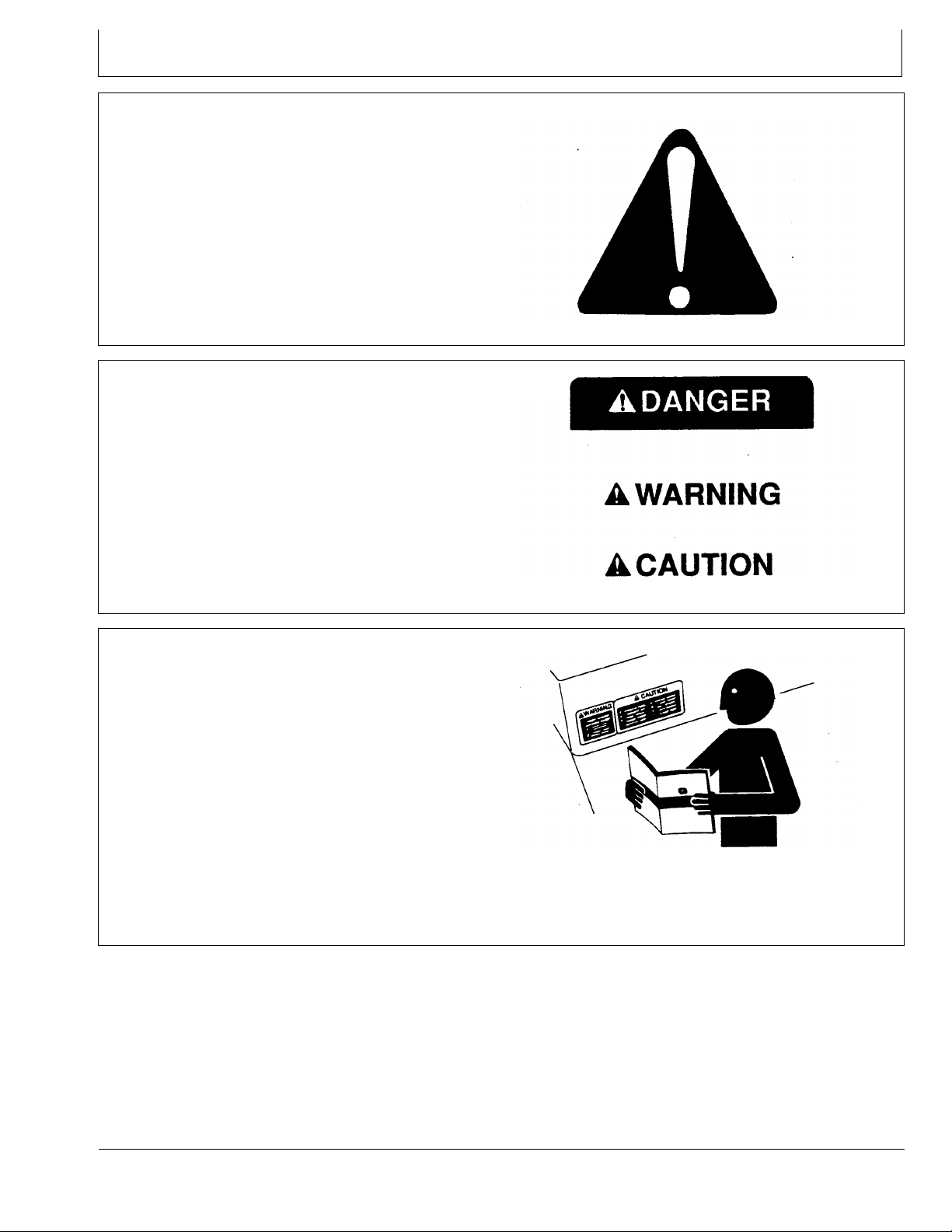
Understand Signal Words
A signal word—DANGER, WARNING, or CAUTION—is
used with the safetyalert symbol. DANGER identifies the
most serious hazards.
DANGER or WARNING safety signs are located near
specific hazards. General precautions are listed on
CAUTION safety signs. CAUTION also calls attention to
safety messages in this manual.
T81389 —UN—07DEC88
DX,ALERT 1929SEP981/1
Follow Safety Instructions
Carefully read all safety messages in this manual and on
your machine safety signs. Keep safety signs in good
condition. Replace missing or damaged safety signs. Be
sure new equipment components and repair parts include
the current safety signs. Replacement safety signs are
available from your John Deere dealer.
There can be additional safety information contained on
parts and components sourced from suppliers that is not
reproduced in this operator’s manual.
Learn how to operate the machine and how to use controls
properly. Do not let anyone operate without instruction.
Keep your machine in proper working condition.
Unauthorized modifications to the machine may impair the
function and/or safety and affect machine life.
TS187 —19—30SEP88
DX,SIGNAL 1903MAR931/1
TS201 —UN—23AUG88
If you do not understand any part of this manual and need
assistance, contact your John Deere dealer.
DX,READ 1916JUN091/1
051
061611
PN=5
Page 6
Safety
Practice Safe Maintenance
Understand service procedure before doing work. Keep
area clean and dry.
Never lubricate, service, or adjust machine while it is
moving. Keep hands, feet , and clothing from powerdriven
parts. Disengage all power and operate controls to relieve
pressure. Lower equipment to the ground. Stop the
engine. Remove the key. Allow machine to cool.
Securely support any machine elements that must be
raised for service work.
Keep all parts in good condition and properly installed.
Fix damage immediately. Replace worn or broken parts.
Remove any buildup of grease, oil, or debris.
On selfpropelled equipment, disconnect battery ground
cable () before making adjustments on electrical systems
or welding on machine.
On towed implements, disconnect wiring harnesses from
tractor before servicing electrical system components or
welding on machine.
Handle Electronic Components and Brackets Safely
Falling while installing or removing electronic components
mounted on equipment can cause serious injury. Use a
ladder or platform to easily reach each mounting location.
Use sturdy and secure footholds and handholds. Do not
install or remove components in wet or icy conditions.
If installing or servicing a RTK base station on a tower or
other tall structure, use a certified climber.
If installing or servicing a global positioning receiver mast
used on an implement, use proper lifting techniques and
wear proper protective equipment. The mast is heavy and
can be awkward to handle. Two people are required when
mounting locations are not accessible from the ground
or from a service platform.
TS218 —UN—23AUG88
DX,SERV 1917FEB991/1
TS249 —UN—23AUG88
DX,WW,RECEIVER 1924AUG101/1
052
061611
PN=6
Page 7
Safety
Operate Guidance Systems Safely
Do not use guidance systems on roadways. Always turn
off (disable) guidance systems before entering a roadway.
Do not attempt to turn on (activate) a guidance system
while transporting on a roadway.
Guidance systems are intended to aid the operator in
performing field operations more efficiently. The operator
is always responsible for the machine path.
Guidance Systems include any application that automates
vehicle steering. This includes, but may not be limited to,
AutoTrac, iGuide, iTEC Pro, ATU, and RowSense.
To prevent injury to the operator and bystanders:
Use Seat Belt Properly
Use a seat belt when you operate with a rollover
protective structure (ROPS) or cab to minimize chance of
injury from an accident such as an overturn.
Do not use a seat belt if operating without a ROPS or cab.
Replace entire seat belt if mounting hardware, buckle,
belt, or retractor show signs of damage.
Inspect seat belt and mounting hardware at least
once a year. Look for signs of loose hardware or belt
damage, such as cuts, fraying, extreme or unusual wear,
discoloration, or abrasion. Replace only with replacement
parts approved for your machine. See your John Deere
dealer.
Never get on or off a moving vehicle.
•
Verify the machine, implement, and guidance system
•
are set up correctly. If using iTEC Pro, verify accurate
boundaries have been defined.
Remain alert and pay attention to the surrounding
•
environment.
Take control of the steering wheel, when necessary, to
•
avoid field hazards, bystanders, equipment, or other
obstacles.
Stop operation if poor visibility conditions impair your
•
ability to operate the machine or identify people or
obstacles in the machine path.
Consider field conditions, visibility, and vehicle
•
configuration when selecting vehicle speed.
JS56696,0000970 1910MAY111/1
DX,ROPS1 1929OCT071/1
TS205 —UN—23AUG88
053
061611
PN=7
Page 8

Theory of Operation
Theory of Operation
Surface Water Pro is a two modular program—basic and
advanced. Surface Water Pro (basic program) is designed
for users to create levees and develop basic ditches
in their fields. Surface Water Pro Plus is an advanced
ditching program that generates a “best fit drain”. Surface
Water Pro Plus calculates the most effective drain in a field
while moving the least amount of soil. This information
is generated from vertical GPS signals calculated from
StarFire 3000 or StarFire iTC receivers. Surface Water
Pro Plus requires both a machine and implement receiver
and cannot operate with just an implement receiver.
Levee applications require John Deere RTK, and ditching
requires either SF2 or RTK signal. For greater accuracy,
we highly recommend the RTK solution.
NOTE: For best accuracy, recalibrate benchmark after
power cycling the quick survey and absolute base
station. When starting up the base station, the
point of reference could shift slightly, so for the
highaccuracy user, consider recalibrating.
Operating with an absolute survey base station
reduces the need for benchmarking. In quick
survey mode, anytime the base is moved or
power is cycled, another calibration is required
for high accuracy users.
John Deere implement mounts must be used
because they reduce vibration and minimize
hardware failures. Vibration mounts help
minimize hardware failures over time, especially
in ditching applications.
Record ditches from HIGH TO LOW elevation.
Cut ditches in either direction.
To ensure highest system accuracy, do not operate
Surface Water Pro and Pro Plus outside a ONE
MILE radius of the Base Station.
Surface Water Pro features available on the GS3 display
and our Apex Desktop Software provide value by offering
ways to manage your topographic data better and ensure
optimum water distribution for crop production. Apex
Surface Water Pro features allow you to unload your GS3
survey data to generate Depression, Flow Direction, and
Drainage maps utilizing GSDNet. You can also manage
your Ditch and Levee Tracks from year to year by editing
cut, slope, or drop of fall. Additionally, layering your
ditch or levee tracks over your yield data displays your
results from the work you completed. See your local John
Deere Dealer or visit our website www.StellarSupport.com
to learn more about these additional features for your
Surface Water Pro program.
Reprogram receivers (Surface Water Pro Plus) at the
vehicle receiver location. Each receiver must be updated
individually every time a software update is available
[3.20D or older]. You cannot have both receivers attached
to the wiring harness when reprogramming.
IMPORTANT: A StarFire iTC receiver, or newer, is
required for Surface Water Pro.
Surface Water Pro Plus does not support an
Implement Receiver Only configuration. Do
not run ditching with an implement receiver
only—both a Machine & Implement receiver
must be used to operate that software.
Surface Water Pro and Pro Plus Survey
function is NOT compatible with Swath Control
Pro. Do not use the survey function in
conjunction with Swath Control Pro.
Surface Water Pro and Pro Plus is NOT
compatible with iGuide Do not use in
conjunction with iGuide.
JS56696,00009F3 1901JUN111/1
101
061611
PN=8
Page 9
Setup
Machine and Implement Setup
Machine must be GreenStar Ready.
To run Surface Water Pro, operator needs:
GreenStar Ready Machine
•
Constant Power
•
Front Extension Harness (3 m or 10 m)
•
Implement Application
•
Implement Receiver (if using Surface Water Pro Plus)
•
To make Surface Water Pro function, set up for the
following:
Machine
•
Machine GPS receiver
•
Implement (Optional for some functions)
•
Implement GPS receiver (Optional)
•
Guidance (Optional)
•
Implement Harness (Optional)
•
Turn GS3 system on after connecting all hardware
components.
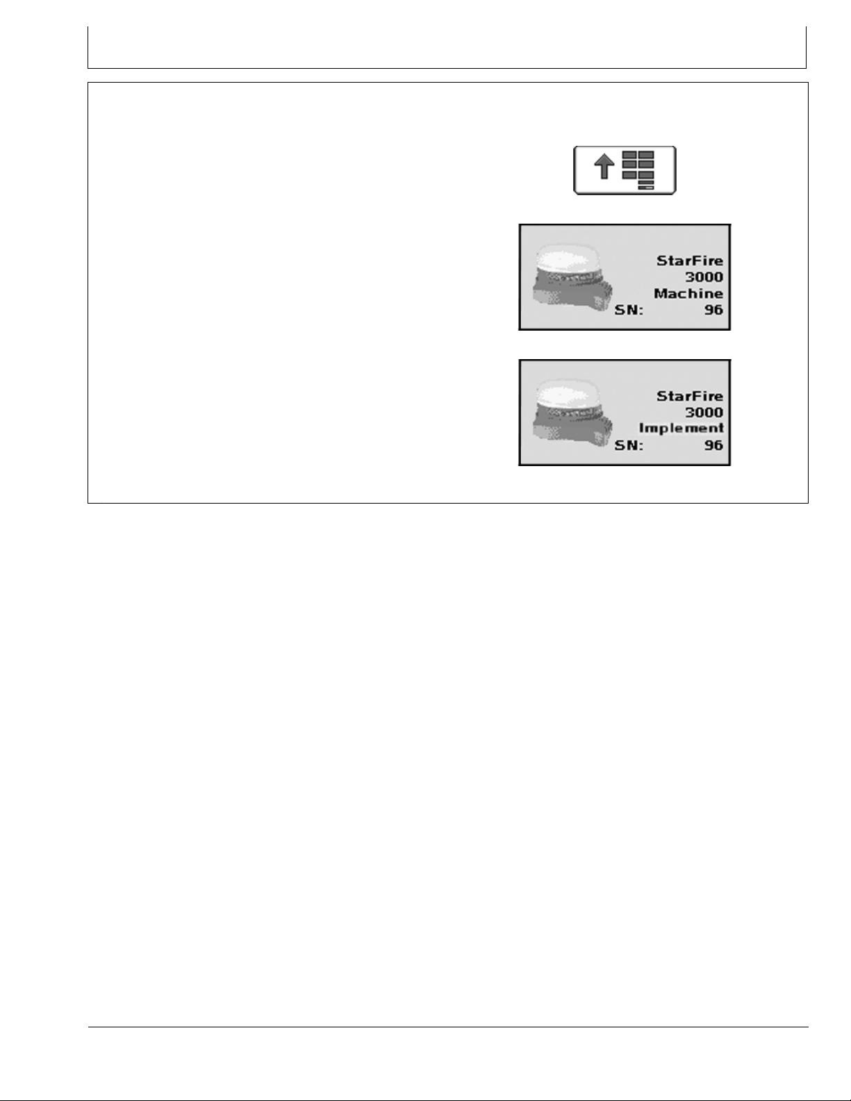
Receivers are used on both the machine and implement
for some ditching applications. If two receivers are used,
verify both StarFire 3000 receiver softkeys (Machine and
Implement) are shown on the display.
PC8663 —UN—05AUG05
PC12601 —UN—10MAY10
PC13595 —UN—11MAY11
MENU Softkey
StarFire 3000 Machine Softkey
StarFire 3000 Implement Softkey
JS56696,00009D1 1919MAY111/1
151
061611
PN=9
Page 10
Machine and Implement Setup
Client, Farm, Field, and Task Setup
This is a required step for boundaries to run survey mode
or to record ditch and levee tracks.
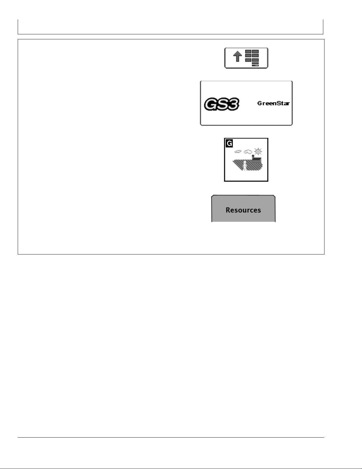
Select MENU softkey >> GREENSTAR 3 PRO softkey >>
RESOURCES/CONDITIONS softkey >> RESOURCES
tab.
The documentation screen allows the setup of operations
and specific details associated with those operations.
IMPORTANT: When setting up the display with
vehicle key in the accessory position (power
on, engine off), turn key to OFF position for
20 seconds BEFORE starting the vehicle.
This ensures the setup data is saved to the
USB flash drive before operating.
If the vehicle is running during setup and
programming, turn off the vehicle with key
in the OFF position and wait 30 seconds
before restarting. This ensures all data is
saved to the USB flash drive.
DO NOT turn the key to the start position directly
from the accessory position. The reduction
in voltage during the starting phase could
result in a loss of all setup data.
PC8663 —UN—05AUG05
PC12685 —UN—14JUL10
PC8676 —UN—05AUG05
PC10857BV —UN—15JUL08
RESOURCES/CONDITIONS softkey
MENU softkey
GREENSTAR 3 PRO softkey
Choose the correct information from CLIENT, FARM,
FIELD, and TASK dropdown box or input new information.
Task is required only if Documentation is used. It is not
needed to set or AutoTrac ditch or levee tracks. Always
setting tasks is a good standard practice though.
Resources tab
JS56696,00009D2 1919MAY111/1
152
061611
PN=10
Page 11
Machine and Implement Setup
Machine Setup
Machine and Implement Offsets are critical for Surface
Water Pro to function.
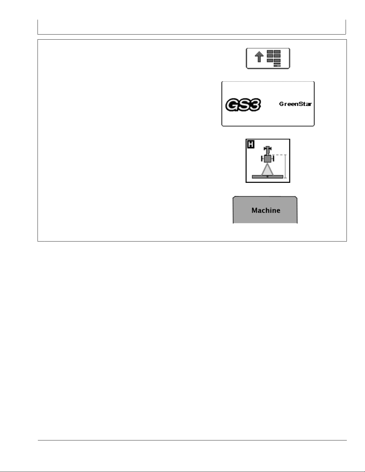
Select MENU softkey >> GREENSTAR 3 PRO softkey
>> EQUIPMENT—allows access to MACHINE and
IMPLEMENT setup screens.
PC8663 —UN—05AUG05
PC12685 —UN—14JUL10
PC8677 —UN—05AUG05
PC10857BP —UN—15JUL08
MENU Softkey
GREENSTAR 3 PRO softkey
EQUIPMENT Softkey
MACHINE tab
Continued on next page JS56696,00009D3 1901JUN111/3
153
061611
PN=11
Page 12
Machine and Implement Setup
Machine Tab
NOTE: All items and changes will be saved under
the current machine name.
Offsets are provided by some ISO implements
and some John Deere tractors. Some list
boxes may be grayed out when the machine
is automatically recognized.
When setting up Surface Water Pro for the
first time, creating a machine name for the
vehicle is recommended. All dimensions and
parameters set for this vehicle are used for
Surface Water Pro operations.
The Machine and Implement tabs are required to be
populated with equipment information such as:
Type
•
Model
•
Name
•
Offsets
•
Machine Type—Vehicle type being used (e.g. Tractor,
Combine, Sprayer).
Machine Model—Model number of the vehicle being
used. For John Deere vehicles, model numbers will be
available from the drop down list.
Machine Name—The name is used to further clarify
which machine is being used. For instance, if there are
two 8430’s in your operation, the machine names may be
“John” and “Deere”, or “84301” and “84302”, or simply
“1” and “2”. However, settings associated to the tractor,
such as turning radius, turn sensitivity, dimensions, etc.,
are stored to the name.
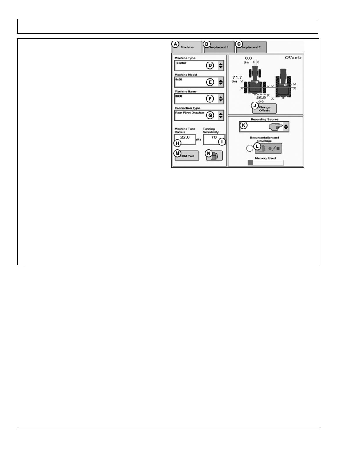
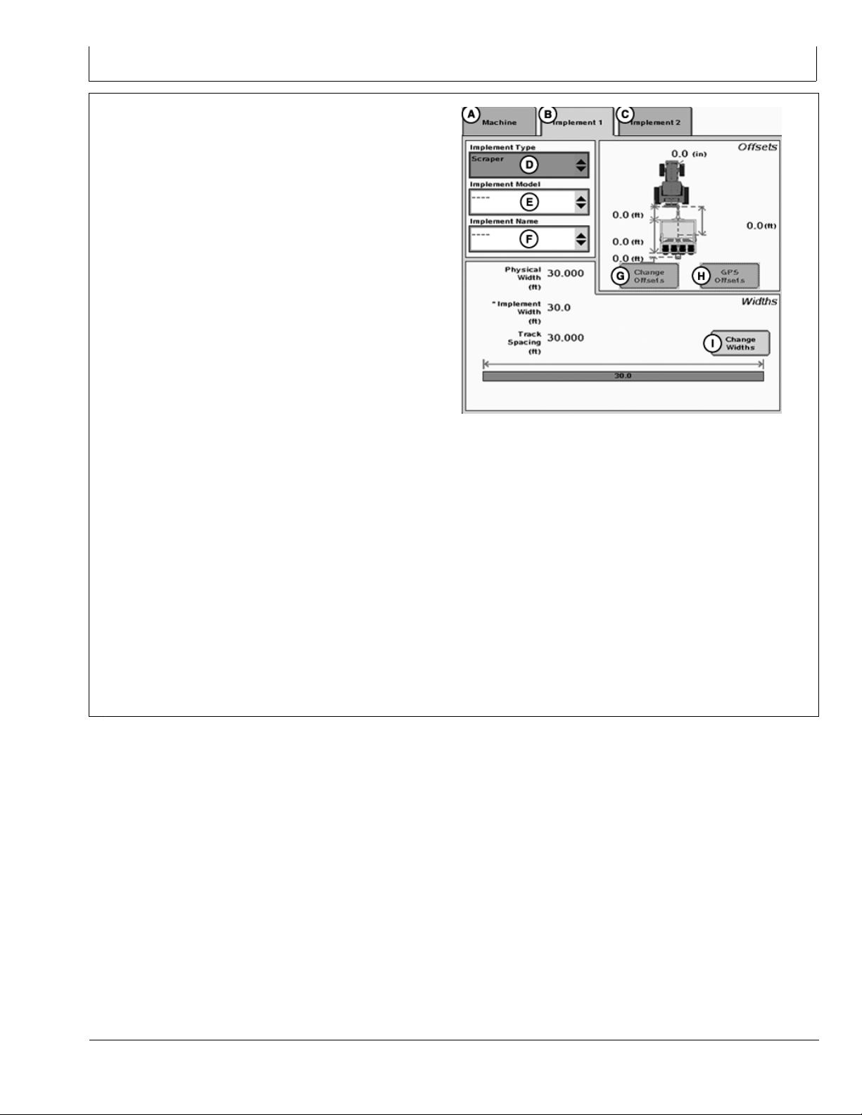
PC13768 —UN—17MAY11
Machine Tab
A—Machine Tab
B—Implement 1 Tab
C—Implement 2 Tab
D—Machine Type dropdown
menu
E—Machine Model dropdown
menu
F— Machine Name dropdown
menu
G—Connection Type
dropdown menu
Continued on next page JS56696,00009D3 1901JUN112/3
H—Machine Turn Radius input
box
I— Turning Sensitivity input
box
J— Change Offsets button
K—Recording Source
dropdown menu
L— Record/Pause button
M—COM Port button
N—Fuel button (Business Pack
/ Europe Only)
154
061611
PN=12
Page 13

Machine and Implement Setup
NOTE: Machine Turn Radius and Turning Sensitivity
are for use with iTEC Pro only.
Machine Turn Radius—How sharp the machine can
turn without an implement attached and without applying
brake pressure. The turn radius is half the diameter as
measured at the center of the rear axle of a row crop
tractor, and the pivot point on tracks and 4WD tractors.
Example: 8030 wheel tractors have a minimum turn
radius of 6.1—6.7 m (20—22 ft). Choose a number to
start with and change as needed for accuracy.
Turning Sensitivity—AutoTrac gain setting when the
vehicle is in an automated turn. This is adjustable by the
operator to improve performance (default 70).
Verify proper dimensions correspond to the Machine
selected.
NOTE: Not all recording sources are available
for all machines.
R—Machine Turn Radius
Machine Offsets
Select CHANGE OFFSETS button on Machine Setup
screen.
Offsets are used to eliminate skips or overlaps due to an
offset receiver.
To enter machine offsets:
Select input box.
•
Enter amount of offset in cm (in.) using numeric keypad
•
and select enter button.
Select the receiver toggle button to move the offset to
•
the right or left of cab center.
If no receiver offset is required, RECEIVER OFFSET input
box should read 0.
Machine offsets:
A) Lateral Distance from centerline of machine to GPS
•
receiver.
B) Inline distance from nonsteering axle to GPS
•
Receiver.
C) Inline distance from nonsteering axle to connection
•
point. The connection point is where the tractor
connects to the implement (drawbar, hitch) except
on 2 pt pivoting implements (large planter). In this
case, measure the distance back to the pivot point
immediately behind the hitch.
(D) Vertical distance from GPS receiver to the ground.
•
NOTE: Offset (D) is for use with Surface Water Pro.
Machine Turn Radius
A—Lateral distance from
centerline of machine to
GPS receiver
B—Inline distance from
nonsteering axle to GPS
receiver
C—Inline distance from
nonsteering axle to
connection point
PC9890 —UN—05FEB07
JS56696,00009D3 1901JUN113/3
PC13269 —UN—28APR11
Machine Offsets
D—Vertical distance from GPS
receiver to the ground
E—Offset Toggle button
F— NonSteering Axle Location
dropdown menu
155
JS56696,00009D4 1911MAY111/1
061611
PN=13
Page 14
Machine and Implement Setup
Implement Setup
Implement 1 Tab
Select MENU softkey >> GREENSTAR 3 PRO softkey >>
EQUIPMENT tab >> IMPLEMENT tab.
PC8663 —UN—05AUG05
PC12685 —UN—14JUL10
PC8677 —UN—05AUG05
Continued on next page JS56696,00009D5 1918MAY111/2
MENU softkey
GREENSTAR 3 PRO softkey
EQUIPMENT softkey
156
061611
PN=14
Page 15
Machine and Implement Setup
Select Change Offsets button (G).
NOTE: All items and changes will be saved under
the current implement name. Implement name
is also the base for transferring data to the
desktop software (if supported).
Verify implement setup before operating Surface
Water Pro Plus. Be sure hydraulic hookups are
in the proper locations and no other changes
to the implement have been made that could
cause unexpected behavior or a change in
vertical receiver position.
When using Surface Water Pro Plus for the
first time, it is necessary to define a name for
the implement being used. All dimensions
and parameters including GPS offsets on the
implement is stored to this name.
For implement setup, the following tabs are required to
be populated:
Implement Type
•
Implement Model
•
Implement Name—information is stored in relation to
•
this name
Verify or Enter implement: Type, Model, and Name in
dropdown boxes.
Implement name allows operator to save implement
dimensions.
NOTE: Select the correct name before changing
any offset dimensions.
Implement Type is required to be selected. Implement
Names are filtered by the type when Implement Model is
selected. For example, scraper or rotary ditcher.
Select CHANGE OFFSET button (G) and proceed to
following Implement Offsets section.
Implement Tab
A—Machine tab
B—Implement 1 tab
C—Implement 2 tab
D—Implement Type dropdown
menu
E—Implement Model
dropdown menu
F— Implement Name
dropdown menu
G—Change Offsets button
H—GPS Offsets button
I— Change Widths button
CHANGE WIDTHS button (I)—IMPLEMENT WIDTHS
are used to calculate CUT VOLUME on the EDIT DRAIN
screen. For example, Implement Width is entered as the
cutting blade width for the scraper.
JS56696,00009D5 1918MAY112/2
PC13799 —UN—02JUN11
157
061611
PN=15
Page 16
Machine and Implement Setup
Implement Offsets
Select MENU softkey >> GREENSTAR 3 PRO softkey >>
EQUIPMENT softkey >> IMPLEMENT tab >> CHANGE
OFFSETS button.
IMPORTANT: Distance (D) is measured when the
implement is in the FULLY RAISED position. This
dimension is critical for accurate ditch designs.
Remember: Always measure to the same
place on the receiver when measuring (that
is, top, middle, and others).
Implement Offsets—Used to define the actual implement
position relative to the tractor. This is important for
ensuring the implement is lined up to the field at the end
of turns and in determining where the implement is for
the Minimize Skips and Minimize Overlaps feature (see
Change Settings on Machine tab).
A) Inline distance from connection point to front of
•
implement. On pulltype implements, think of this as the
tongue. For more precision, it is actually the dimension
from the pinbolt to the front side of where the work gets
done (front ranks of field cultivator, seed drop point on a
planter).
B) Working Length of the implement. On ground
•
engagement tools, this is the distance from the front
rank of sweeps or points to the rear rank. Refer to
implement manufacturer’s Operator’s Manual for this
value.
C) Lateral distance from connection point to control point
•
of implement. This is the lateral distance from the center
of the tractor to the center of the implement which will
be 0.0 for most common implements. This dimension is
used to alert the operator to potential collisions. This is
critical for proper endturn performance and may need
to be adjusted.
D) Inline distance from connection point to control
•
point of implement. In many cases, this distance will be
from the connection point to the carrying wheels. For
proper turns, measure this distance with implement at
the height it typically will be at while turning.
NOTE: These dimensions may need to be adjusted
for finetuning performance in the field.
IMPORTANT: Ensure vertical distance (D) is measured
from the GPS receiver to the ground when the
implement is in the FULLY RAISED position.
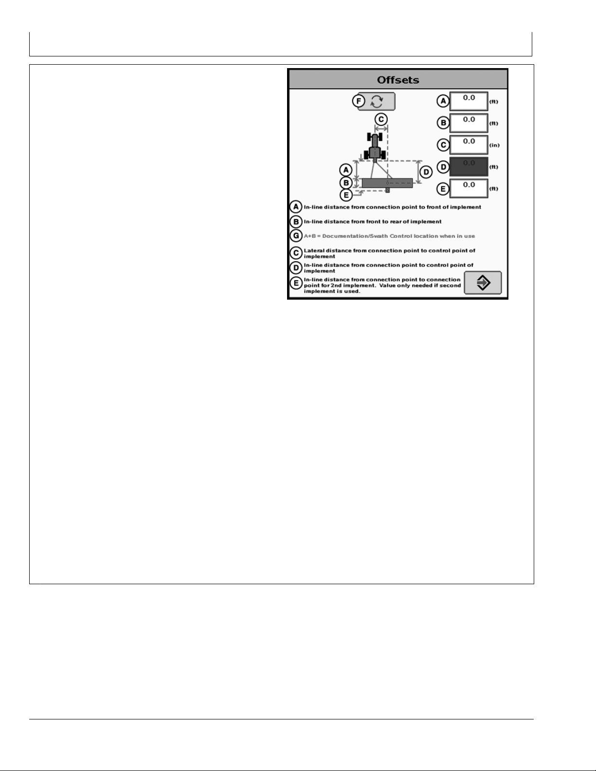
PC11405 —UN—15OCT08
Implement Offsets
A—Inline distance from
connection point to front of
implement.
B—Inline distance from front
to rear of implement.
C—Lateral distance from
connection point to control
point of implement.
D—Inline distance from
connection point to control
point of implement.
E—Inline distance from
connection point to
connection point for
second implement. Value
only needed if second
implement is used.
F— Offset Toggle button
G—A+B = Documentation /
Swath Control location
when in use.
Remember: Always measure to the exact
same place on the receiver when measuring
(that is, top, middle, and others.).
NOTE: For a rotary ditcher, dimension (C) refers to
the distance from the receiver to the cutting
edge. On a rotary ditcher the cutting edge is the
bottom of the paddle wheel, since this contacts
the soil first. This dimension could be adjusted
depending on individual requirements.
Continued on next page JS56696,00009D6 1911MAY111/4
158
061611
PN=16
Page 17
Machine and Implement Setup
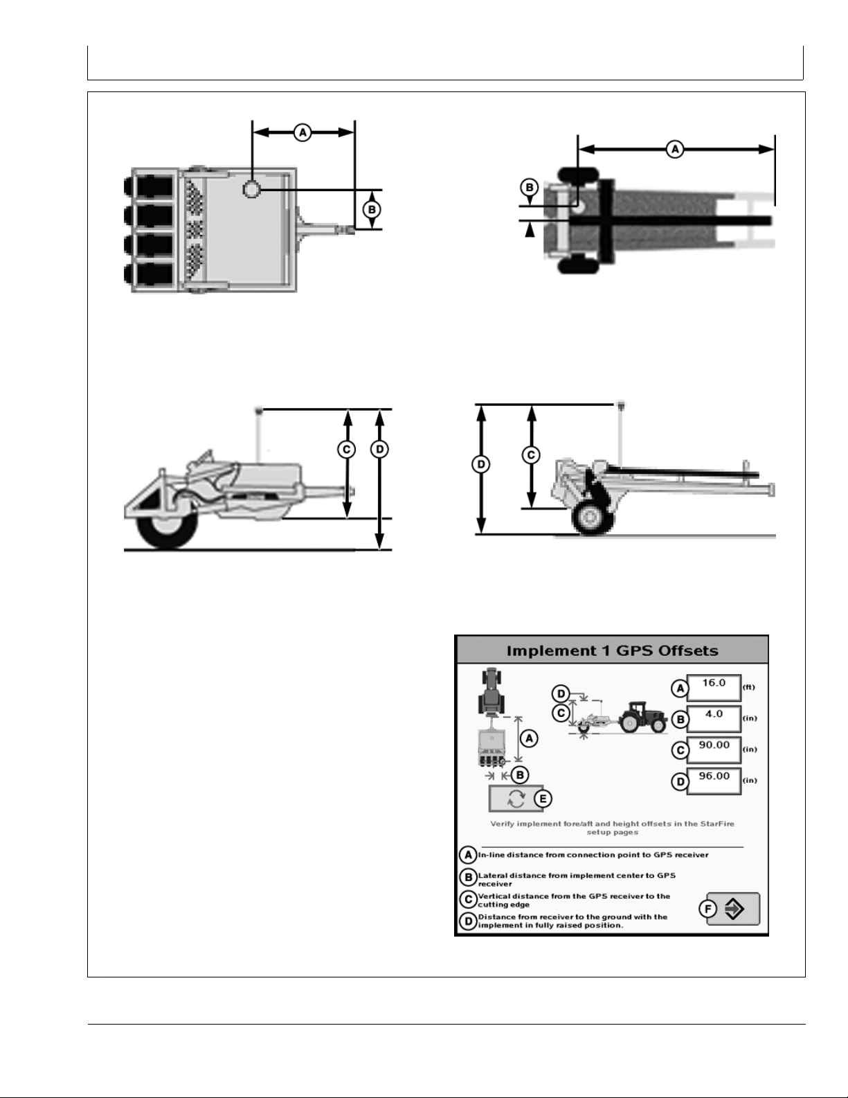
Scraper Overhead
Scraper Profile
A—Inline distance from
connection pivot point to
GPS receiver.
B—Lateral distance from
implement center to GPS
receiver.
C—Vertical distance from the
GPS receiver to the cutting
edge.
D—Vertical distance from the
GPS receiver to the ground
in the fully raised position.
E—Offset Toggle button
F— Accept button
PC10376 —UN—13OCT07
PC10375A —UN—14OCT07
PC10378A —UN—14OCT07
Rotary Ditcher Overhead
PC10377 —UN—13OCT07
Pull Type Rotary Ditcher Profile
Implement GPS Offsets
Continued on next page JS56696,00009D6 1911MAY112/4
159
PC13801 —UN—02JUN11
061611
PN=17
Page 18
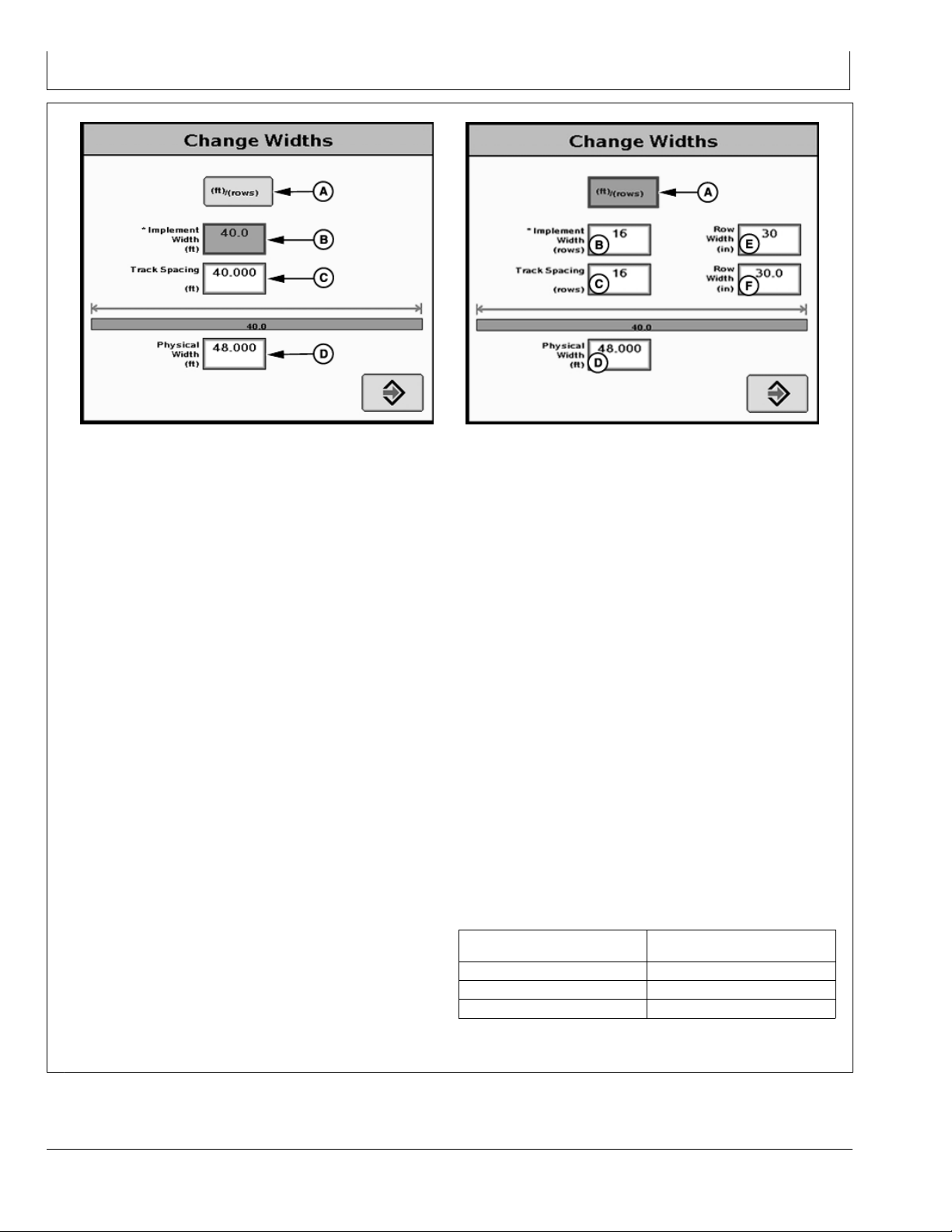
Machine and Implement Setup
Track Spacing
A—m (ft)/(rows) button
B—Implement Width
C—Track Spacing
D—Physical Width
Implement Widths—Used to enter implement width
and track spacing for guidance. This value is also used
to calculate total area when documenting the operation.
Verify implement type, model, name, implement width and
track spacing when changing implements. Implement
width and track spacing are independent of each other.
NOTE: IMPLEMENT tab will show HEADER for
Combines, ROW UNITS for Cotton Pickers,
and BOOM for Sprayer.
Implement width may come from controller on
select controllers such as SeedStar.
In some cases, a higher degree of precision can be
achieved for track spacing when track spacing is
entered in by rows instead of feet. More decimal
places are used in the track spacing calculation
when entered in by rows versus the three decimal
places allowed when entered by feet.
Defining Implement Width and Track Spacing.
Implement width and track spacing can be defined two
ways: enter the working width of the implement, or enter
the number of rows and the row spacing. To toggle
between these two, select the m (ft)/(rows) button.
Implement Width m (ft)—enter total implement working
•
width
Implement Width rows—enter number of rows and the
•
row spacing in inches
Track Spacing—Used in guidance for how far each pass
is from the last pass. It is entered the same way as
Implement Width. For “perfect” guess rows, this distance
will be the same as Implement Width. To ensure some
PC9902 —UN—09JAN07
Track Spacing
E—Row Width
PC9903 —UN—09JAN07
overlap for tillage or spraying, or to account for some
GPS drift, you may choose to make the Track Spacing
somewhat less than the Implement Width.
Physical Width—The actual width of the entire implement
when being used in the field when the implement is raised.
It is sometimes larger than Implement Width.
Using a planter as an example, the marker arms and
blades are wider than the working width. This width
needs to be entered if markers are not used, or are used
and completely folded on the ends. If markers are only
partially folded during turns, enter this larger dimension.
IMPORTANT: Width measurements are used to help
alert an operator of potential intersections
between the implement and an impassable
boundary. The operator still needs to be aware
of potential collisions if there are times the
implement is wider than the dimension entered
(e.g. marker arm lowered). If markers are used
in the field, add the width of both markers to
give ultimate alarms of possible intersections.
NOTE: As a buffer to avoid obstacles, additional Physical
Width may be added to the implement to compensate
for several things, one of these being GPS drift.
Signal
RTK
SF2 0.9 m (3 ft)
SF1 3.4 m (11 ft)
Physical Width Table
Continued on next page JS56696,00009D6 1911MAY113/4
Approximate Physical Width
added to Implement
0.6 m (2 ft)
1510
061611
PN=18
Page 19

Machine and Implement Setup
NOTE: If the physical width is less than the implement
(working) width, a message will appear as a
reminder that this is not usually correct (A 16R30
planter is physically wider than its 12.2 m (40 ft)
working width). An example where the working
width is wider than the physical width is a dry
fertilizer spreader—it spreads much farther than
the physical width of the buggy.
Confirm Configuration—The
physical width is
smaller than the
implement width which
may not allow detection
of all intersections
with impassable
boundaries.
PC12865 —UN—16SEP10
Confirm Configuration
JS56696,00009D6 1911MAY114/4
Machine GPS Receiver Setup
Select MENU softkey >> STARFIRE 3000 MACHINE
softkey >> SETUP tab.
This screen allows access to StarFire 3000 setup pages.
See the StarFire 3000 operator’s manual to set up the
receiver for the machine.
NOTE: To ensure highest accuracy, do not operate
Surface Water Pro and Pro Plus outside a 1.6 km
(ONE MILE) radius of the Base Station.
If your RTK kit came with a 7.5 cm (3 in.) antenna
extension it is suggested to discard the extension
and use either the 23 or 30 cm (9 or 12 in.)
onepeice antenna. Use of the 7.5 cm (3 in.)
extension on the implement receiver could result
in the loss of the antenna due severe vibration
created by some implements.
PC8663 —UN—05AUG05
PC12042 —UN—08MAY09
PC10857BR —UN—15JUL08
PC13406 —UN—20APR11
StarFire 3000 Receiver
MENU Softkey
StarFire 3000 Machine Softkey
1511
Setup tab
JS56696,00009D7 1919MAY111/1
061611
PN=19
Page 20

Machine and Implement Setup
Implement GPS Receiver Setup
IMPORTANT: Surface Water Pro Plus does not support
an Implement Receiver Only configuration. Do
not run ditching with an implement receiver
only—both a Machine and Implement receiver
must be used to operate ditching software.
Select MENU softkey >> STARFIRE 3000 IMPLEMENT
softkey >> SETUP tab.
This screen allows access to StarFire 3000 setup on the
implement.
NOTE: If using a two receiver solution, Original StarFire
receivers cannot be used on the implement
or the machine. This is due to the address
arbitration between the two at startup.
The number below the text on the StarFire 3000 Softkey
shows the serial number of the receiver.
On the StarFire Main page, the receiver definition
(Machine or Implement) is shown in the headline.
NOTE: Mount the receiver directly over the cutting edge
of the implement or a position with 1:1 vertical
movement of the receiver and cutting edge.
PC8663 —UN—05AUG05
PC13595 —UN—11MAY11
PC10857BR —UN—15JUL08
StarFire 3000 Implement Softkey
MENU Softkey
Setup tab
For future reference, mark the two receivers so it is
clear which receiver is mounted on the machine and
which receiver is mounted on the implement.
JS56696,00009D8 1917MAY111/3
Select the implement receiver softkey and verify its
receiver location is set to implement.
Reconnect the machine receiver if it was disconnected
before continuing. Select Correction Mode (E) to match
the desired correction mode. Ditching requires both
receivers to have the same differential correction level
and subscription.
Select the correct mounting direction (G). The preferred
mounting direction for the implement is forward. Adjust
receiver bracket on implement to match that if possible.
NOTE: Only SF2 and RTK can be used for ditching.
Only RTK can be used for levee work.
Height (I) is the same as machine or
implement D offset.
A—INFO tab
B—SETUP tab
C—ACTIVATIONS tab
D—SERIAL PORT tab
E—CORRECTION MODE
dropdown box
F— DEFAULT check box
G—MOUNT DIRECTION
dropdown box
H—FORE/AFT input box
I— HEIGHT input box
JK—ENABLE QUICKSTART
input box
K—HOURS ON AFTER
SHUTDOWN dropdown
box
L— TCM On
M—TCM OFF
N—TCM On and Off Toggle
button
O—TCM Calibrate button
PC13605 —UN—11MAY11
StarFire 3000 Implement Main, Setup tab
Continued on next page JS56696,00009D8 1917MAY112/3
1512
061611
PN=20
Page 21

Machine and Implement Setup
Enter the correct receiver height above the ground:
Dimension D—fully raise the implement and measure
from the ground to the middle of the receiver (inches).
Dimension C—measure from the middle of the receiver to
the cutting edge.
IMPORTANT: Always measure to the exact same
place on the receiver when measuring.
Enter 0 for the For and Aft dimension for the implement
receiver if the receiver is mounted over the cutting
edge—this space is reserved for future enhancement.
For optimized performance make the Hours On After
Shutdown the same value as on the machine receiver
(24 is recommended).
NOTE: When performing a TCM calibration on the
implement receiver, the wheels of the main frame,
to which the implement receiver is mounted,
need to be in the same location after turning
implement around so the righthand wheels are
in the same place as where the lefthand wheels
were. A smooth level surface is recommended
while performing a TCM calibration.
PC13406 —UN—20APR11
StarFire 3000 Receiver
Perform a TCM calibration each time the receiver
is moved to a different implement or vehicle.
The implement TCM is used for determining
vertical position of the blade.
For more information refer to your StarFire 3000 operators
manual.
JS56696,00009D8 1917MAY113/3
1513
061611
PN=21
Page 22

Satellite Information
Satellite Information Softkey
Select MENU softkey >> STARFIRE 3000 softkey >>
SATELLITE INFORMATION softkey.
The StarFire 3000 Satellite Information screen contains
Sky Plot, Graph, and Predictor tabs.
PC8663 —UN—05AUG05
PC13702 —UN—12MAY11
PC8682 —UN—05AUG05
Continued on next page JS56696,0000A07 1902JUN111/3
SATELLITE INFORMATION softkey
MENU softkey
STARFIRE 3000 softkey
201
061611
PN=22
Page 23

Satellite Information
Sky Plot tab
The Sky Plot tab shows where the satellites are in relation
to the vehicles receiver, allowing the operator to look at
satellite geometry.
Reading Satellite Sky Plot
Sky Plot is fixed so North is always at the top of the
•
screen.
Satellites are displayed as their satellite ID number that
•
corresponds to the Satellite Tracking Chart located to
the right of the Sky Plot.
Red—indicates satellite is in search mode
Blue—indicates satellite is being tracked
Green—indicates satellite is OK (being used for
corrections)
Sky Plot consists of 3 concentric rings depicting 0, 30,
•
and 60 degrees of elevation with directional crossbar
intersection representing 90 degrees of elevation.
Gray radial lines extending from center of Sky Plot
•
represent azimuth. They are spaced 30 degrees apart
and represent 30 and 60 degrees.
Directional crossbar representing North, South, East,
•
and West also represent azimuth at 0, 90, 180, and 270
degrees.
W1 and W2 (WAAS or EGNOS) satellites and inmarsat
•
satellites are not shown in Sky Plot.
A—Sky Plot tab
B—Graph tab
C—Predictor
D—Satellites in Solution
E—Satellites Above Elevation
Mask
F— Satellites Tracked
PC13703 —UN—12MAY11
G—Corrections Age
H—VDOP
I— HDOP
J— PDOP
K—Satellites on Sky Plot
L— Satellite Tracking
Satellite Tracking Chart
SAT ID—(Satellite Identification Number) Identification
•
number for GPS Satellite.
ELV—(Position Elevation) Elevation in degrees above
•
horizon for GPS satellite position.
AZM—(Position Azimuth) Azimuth in degrees from true
•
North for GPS satellite.
L1 SNR—(L1 Signal to Noise Ratio) Signal strength for
•
L1 GPS signal (signal to noise ratio).
L2 SNR—(L2 Signal to Noise Ratio) Signal strength for
•
L2 GPS signal (signal to noise ratio).
Status—(GPS Signal Status) Status of GPS signal.
•
Search—searching for satellite signal.
Track—tracking satellite signal and using it for
positioning.
OK—tracking satellite signal and using it for
positioning.
OK SF1—Tracking satellite signal and using it for
positioning with StarFire single frequency.
OK SF2—Tracking satellite signal and using it for
positioning with StarFire dual frequency.
Satellite Tracking Information
Satellite Tracking information is displayed at bottom of
SKY PLOT and GRAPH tabs.
Satellites in Solution—number of satellites used to
•
compute position.
Satellites Above Elevation Mask—total number of GPS
•
satellites available to receiver that are above seven
degree elevation mask.
Satellites Tracked – total number of GPS satellites
•
tracked by receiver.
Corrections Age (sec.)—age of differential correction
•
signal to GPS (normally less than 10 seconds).
VDOP—Vertical Dilution of Precision.
•
below 2.0 optimal
2.0—2.5 desirable
2.5 or greater can indicate poor vertical accuracy
performance. AMS does not recommend operating
above this value.
HDOP—Horizontal Dilution of Precision.
•
PDOP—Positional Dilution of Precision is an indicator of
•
GPS satellite geometry as viewed by receiver. A lower
PDOP indicates better satellite geometry for calculating
both horizontal and vertical position.
Continued on next page JS56696,0000A07 1902JUN112/3
202
061611
PN=23
Page 24

Satellite Information
Graph
A graph illustrating L1 and L2 SNR values.
Bars are colored to satellites current status.
•
SNR values (colored bar) should be above dashed line
•
that runs horizontally across bar graph.
NOTE: Only GREEN bars are used in calculation of
PDOP, VDOP, AND HDOP. SNR’s are considered
good if above dashed line.
A—SkyPlot tab
B—Graph tab
C—Predictor tab
D—PDOP
PC13704 —UN—12MAY11
JS56696,0000A07 1902JUN113/3
203
061611
PN=24
Page 25

Surface Water Pro Setup
Setup tab
Select MENU softkey >> GREENSTAR 3 PRO softkey >>
Surface Water PRO softkey >> SETUP tab.
PC8663 —UN—05AUG05
PC12685 —UN—14JUL10
PC10379 —UN—14OCT07
PC10857BR —UN—15JUL08
MENU softkey
GREENSTAR 3 PRO softkey
Surface Water PRO softkey
Continued on next page JS56696,00009DA 1917MAY111/2
Setup tab
251
061611
PN=25
Page 26

Surface Water Pro Setup
Set SURVEY MODE dropdown box (E) and SURVEY
INTERVAL input box (F).
Distance—feet. Points are determined by feet traveled.
•
This method compensates for speed changes.
Time—seconds. Points are determined every x
•
seconds. This method does not compensate for
changes in vehicle speed.
Set SURVEY RECEIVER SOURCE dropdown box
(G)—Machine or Implement.
BENCHMARK SETTINGS button (H)—the operator can
define a benchmark and calibrate a differential. This is
primarily used in quick survey base setups. A benchmark
is not needed when a permanent base is used.
VERTICAL ACCURACY BAR STEP input box (I) (Surface
Water Pro Plus)—enter the step size for the vertical
accuracy bar. The Vertical Accuracy Bar Step is used
to specify the vertical distance that triggers the vertical
lightbar arrows (the difference between drain design
height and the cutting blade height) For example, if the
Vertical accuracy Step Bar size is set to 2.5 cm (1 in.) and
the cutting edge is 7.6 cm (3 in.) above the desired height,
three arrows are highlighted.
MAP SETTINGS button (J)—selecting this button displays
a MAP SETTINGS screen where the operator can edit
the map settings.
AUTONAME LEVEE TRACKS check box (K)—when
checked, automatically generates levee track names by
numbers, starting at 1 and increment each time a new
levee is created, assuming the next number has not
already been used as a name. When unchecked, the
operator is required to name new ditch tracks.
A—Survey tab
B—Levee tab
C—Ditch tab
D—Setup tab
E—Survey Mode dropdown
box
F— Survey Interval (sec) input
box
G—Receiver Source
dropdown box
H—Benchmark Settings button
I— Vertical Accuracy Bar Step
Size input box
J— Map Settings button
K—AutoName Levee Tracks
check box
L— AutoName Ditch Tracks
check box
AUTONAME DITCH TRACKS check box (L)—when
checked, automatically generates ditch track names
by numbers, starting at 1 and increment each time a
new ditch is created, assuming the next number has not
already been used as a name. When unchecked, the
operator is required to name new ditch tracks.
JS56696,00009DA 1917MAY112/2
PC13606 —UN—12MAY11
252
061611
PN=26
Page 27

Surface Water Pro Setup
Benchmark Settings
Calibrating to a Benchmark Control Point allows the
QuickSurvey user to achieve repeatability accuracy
equivalent to the permanent base station.
Select MENU softkey >> GREENSTAR 3 PRO softkey
>> SURFACE WATER PRO softkey >> SETUP tab >>
BENCHMARK SETTINGS button.
This screen allows the operator to define one control point
and calibrate a differential on a per field basis.
CONTROL POINT dropdown box (A)—shows existing
control point for the field and “New” which allows the
operator to create a control point. Changing the selection
updates the displayed position data:
SET POINT button (B)—sets the position for the selected
control point.
MAST HEIGHT input box (C)—enter the mast height. If
the implement receiver is used to set the control point,
the height dimension on a scraper is equal to Implement
Dimension C.
PC13770 —UN—17MAY11
CALIBRATE button (D)—calculates the difference
between the current GPS reading and the GPS position
of the selected control point and store that value as the
differential for the field.
Enabled only when a valid control point is selected in
•
the CONTROL POINT dropdown box.
Disabled if GPS is not available.
•
Enabled only when the operator has entered a valid
•
mast height.
CLEAR button (E)—clears the differential setting.
ENTER button (F)—save changes and return to the
previous page.
A—CONTROL POINT
dropdown box
B—SET POINT button
C—MAST HEIGHT input box
D—CALIBRATE button
E—CLEAR button
F— ENTER button
NOTE: Place a flag or marker down to identify benchmark
location for later calibration. Do not mark such
places as public roadways or bridges because
it is hazardous to other drivers. Document
Control Point location for later use.
JS56696,00009DB 1912MAY111/1
253
061611
PN=27
Page 28

Surface Water Pro Setup
Creating a Benchmark Control Point
1. Position receiver on the control point.
NOTE: The StarFire 3000 receiver CANNOT be
moved during the creation of a Benchmark
Control Point. Any movement causes the
Benchmark to be inaccurate
2. From CONTROL POINT dropdown box (A), select
NEW.
3. Type in name of control point.
4. Enter mast height in the MAST HEIGHT input box (C).
If the implement receiver is used to set the control
point, the height dimension on a scraper is equal to
Implement Dimension C if blade is lowered to the
ground or Implement Dimension D if blade is fully
raised.
5. Select SET POINT button (B).
6. Select ENTER button (F).
A—CONTROL POINT
dropdown box
B—SET POINT button
C—MAST HEIGHT input box
D—CALIBRATE button
E—CLEAR button
F— ENTER button
Calibrating to a Control Point
1. Position receiver on the control point.
NOTE: The StarFire 3000 receiver CANNOT be
moved during the calibration of a Benchmark
Control Point. Any movement causes the
calibration to be inaccurate.
2. Enter mast height (C) if it is at a different height than
when benchmark was set.
3. Select CALIBRATE button (D).
4. Select ENTER button (F).
A—CONTROL POINT
dropdown box
B—SET POINT button
C—MAST HEIGHT input box
D—CALIBRATE button
E—CLEAR button
F— ENTER button
PC13770 —UN—17MAY11
JS56696,00009DC 1912MAY111/1
254
PC13770 —UN—17MAY11
JS56696,00009DD 1917MAY111/1
061611
PN=28
Page 29

Boundary and Tracking Setup
Record an External Boundary
Select MENU softkey >> GREENSTAR 3 PRO softkey >>
MAPPING softkey >> BOUNDARIES tab.
PC8663 —UN—05AUG05
PC12685 —UN—14JUL10
PC8672 —UN—05AUG05
PC10632 —UN—15JUL08
MENU softkey
GREENSTAR 3 PRO softkey
MAPPING softkey
Continued on next page JS56696,00009DE 1919MAY111/2
Boundaries tab
301
061611
PN=29
Page 30

Boundary and Tracking Setup
IMPORTANT: Accurate boundaries are necessary
for the system to execute functions
accurately on the ground.
BOUNDARIES tab—allows operator to record exterior
field boundaries. Boundaries are saved on the USB flash
drive.
Client, farm, and field are required before setting up
boundaries.
NOTE: It is highly recommended to have boundaries but
they are not required for ditch or levee tracks.
Survey function on the Surface Water Pro softkey requires
an exterior field boundary. In order to create an elevation
map as a background layer, an exterior field boundary is
required from either the GS3 display or from Apex.
A—MAPS tab
B—BOUNDARIES tab
C—FLAGS tab
D—CLIENT dropdown box
E—FARM dropdown box
F— FIELD dropdown box
G—TYPE dropdown box
H—HEADLAND GROUP
dropdown box
I— DRIVE BOUNDARY check
box
J— HEADLAND INDICATOR
check box
K—BOUNDARY OFFSET input
box
L— BOUNDARY OFFSET toggle
M—RECORD or PAUSE button
N—STOP RECORDING button
PC13701 —UN—12MAY11
Boundaries with Driven Exterior Headland Boundary
JS56696,00009DE 1919MAY112/2
302
061611
PN=30
Page 31

Survey
How to Survey a Field
Surface Water Pro provides a Survey tab for the purpose
of performing a field survey. When a survey is performed,
the RCD (GS3) creates a survey file for the field that
contains a collection of data points. Each point represents
a specific latitude and longitude position within the field for
which an elevation value is stored.
The data collected can be valuable to create informational
maps. Any maps created from this data is only as good
as the quality of the data that creates it. In order to create
quality maps from your field survey data, be sure to
perform your field survey to the highest quality. As a start,
please observe the following guidelines as a minimum for
performing a field survey.
1. Use the correct differential correction for your
application. It is recommended an RTK correction
be used for the highest accuracy and quality survey
data. An SF2 correction is allowed for surveying your
fields, but only after consulting your dealer to see if
it is right for your application. An RTK correction is
always utilized for flat to rolling field terrain. Using
an inappropriate differential correction for collecting
elevation data leads to inaccurate maps.
2. Make the first pass very close to the exterior field
boundary, when collecting survey data, to ensure
sufficient data around the perimeter of the field. Make
the second pass around the field boundary but slightly
offset inward from the first pass. Offset the second
pass approximately 15 m (50 ft.).
3. Conducting a thorough survey can be done by
setting up straight track lines and parallel tracking
off them through the field. Set up straight track
lines with intervals depending on the field being
surveyed.
Fields with significant elevation changes and slopes
•
— track spacing of 7.5—15 m (25—50 ft.) is
recommended.
Flatter fields — a track spacing of 15 m (50 ft.) is
•
recommended.
Flat to precision leveled ground — a track spacing of
•
15—30 m (50—100 ft.).
Do not exceed 50 m (164 ft.) track spacing for
surveying purposes.
4. Two forms of Survey recording types are available:
Distance Base—ideal for low speed surveys and
•
consistently spaced at userdefined distances.
Time Based—suited to higher speed surveying and
•
the distance between the points varies with the
speed at which the survey is recorded.
5. Ensure that the entire field has been covered. Do not
skip parts of the field because they are inaccessible
due to wet or muddy conditions; you are in a hurry;
you think you do not have time to finish properly. This
has a negative impact on the quality of your maps
generated from your collected data. It is important to
cover the entire field.
6. It is also a good idea to survey the bottom of existing
ditches within the field, and at a minimum ditches with
measurable width and depth. Utilizing parallel tracking
with straight track can cause the user to miss areas
of interest for surveying, for example the bottom of
a main ditch which can have measurable width and
depth.
Survey Mode is designed to allow an operator to collect
elevation and position data as a separate operation. From
this data, topographical information can be created and
displayed. The accuracy level while surveying determines
the accuracy of the topographical maps. Elevation
data points can also be obtained for log files created
while performing field operations such as planting and
combining.
NOTE: Survey Mode is not allowed with Swath Control Pro.
Continued on next page JS56696,00009E0 1918MAY111/3
351
061611
PN=31
Page 32

Survey
Select MENU softkey >> GREENSTAR 3 PRO softkey >>
SURFACE WATER PRO softkey >> SURVEY tab.
PC8663 —UN—05AUG05
PC12685 —UN—14JUL10
PC10379 —UN—14OCT07
PC10857BW —UN—15JUL08
SURFACE WATER PRO softkey
MENU softkey
GREENSTAR 3 PRO softkey
1. Record an external boundary for the field (Required).
2. Set up straight track for your survey pattern (optional).
Set survey mode and interval on Setup tab (D).
3. Select Record button (E) (Located on Survey tab (A)).
NOTE: Light (F) begins blinking red to signify
recording status as ON.
4. To stop surveying, select the Record button (E) again.
NOTE: Light (F) blinks rapidly until all data is saved
to the storage device.
Background layer cannot be changed during
survey recording. To change the background
layer, stop survey recording, change background
layer, and restart survey recording.
A—Survey tab
B—Levee tab
C—Ditch tab
D—Setup tab
E—Record button
F— Indicator Light
Survey tab
JS56696,00009E0 1918MAY112/3
PC13705 —UN—17MAY11
GreenStar 3 Pro—Water Management, SURVEY tab
JS56696,00009E0 1918MAY113/3
352
061611
PN=32
Page 33

Ditch
Setup Operation
Select MENU softkey >> GREENSTAR 3 PRO softkey >>
DOCUMENTATION softkey >> NEW tab.
PC8663 —UN—05AUG05
PC12685 —UN—14JUL10
PC8678 —UN—05AUG05
PC10857BT —UN—15JUL08
MENU softkey
GREENSTAR 3 PRO softkey
DOCUMENTATION softkey
Continued on next page JS56696,00009E1 1912MAY111/2
New tab
401
061611
PN=33
Page 34

Ditch
GreenStar 3 Pro—Documentation, New tab
A—New tab
B—Tillage button
C—Planting/Seeding button
D—Product Application button
E—Harvest button
F— Water Management button
Select Water Management button (F) and type (I).
IMPORTANT: Surface Water Pro Plus does not support
an Implement Receiver Only configuration. Do
not run ditching with an implement receiver
PC13740 —UN—16MAY11
GreenStar 3 Pro—Documentation, Water Management tab
G—Other button
H—Water Management tab
I— Type dropdown menu
J— Remove button
only. AMachine and Implement receiver must
be used to operate ditching software.
PC13707 —UN—17MAY11
JS56696,00009E1 1912MAY112/2
402
061611
PN=34
Page 35

Ditch
Set Tracking Mode to Ditch Track
NOTE: Ditches must be recorded from high to low, but can
be cut in either direction. If the track is not recorded
from high to low, the drain design software in
Surface Water Pro Plus does not function correctly.
Select MENU softkey >> GREENSTAR 3 PRO softkey >>
GUIDANCE softkey >> GUIDANCE SETTINGS tab.
Select DITCH TRACK in TRACKING MODE dropdown
box (A).
NOTE: Selecting Ditch Mode can be found in the GS3
Guidance area, not in the Surface Water Pro area.
A—Guidance Settings tab
B—Tracking Mode dropdown
box
PC8663 —UN—05AUG05
PC12685 —UN—14JUL10
PC8673 —UN—14OCT07
PC10857BU —UN—15JUL08
MENU softkey
GREENSTAR 3 PRO softkey
GUIDANCE softkey
PC13728 —UN—17MAY11
Guidance Settings tab
JS56696,00009E2 1912MAY111/1
403
061611
PN=35
Page 36

Recorded Path for Ditching
Ditch
PC10857DW —UN—07OCT08
A—Path Recorded by Tractor for
AutoTrac
B—Path Recorded by Implement
for Ditch Track
C—Start of recorded Tractor Path
D—End of recorded Tractor Path
If an implement receiver is used to record elevation data
for ditch track, the resulting path differs from the AutoTrac
path. AutoTrac is always based off of the receiver on the
tractor. AutoTrac and Ditch Track paths have different
starting and stopping points. Although the tractor may
Record Ditch Track
Select MENU softkey >> GREENSTAR 3 PRO softkey
>> SURFACE WATER PRO softkey >> DITCH tab >>
OVERHEAD VIEW button.
E—Start of recorded Implement
Path
F— End of recorded Implement
Path
be driving on the Ditch path, ditching guidance does not
become active until the implement receiver is on the cut
line path. The cut line is updated when the implement
receiver is over the recorded ditch.
JS56696,00009E3 1916MAY111/1
PC8663 —UN—05AUG05
PC12685 —UN—14JUL10
PC10379 —UN—14OCT07
MENU softkey
GREENSTAR 3 PRO softkey
PC10857BS —UN—15JUL08
Continued on next page JS56696,00009E4 1918MAY111/2
SURFACE WATER PRO softkey
Ditch tab
404
061611
PN=36
Page 37

1. Drive to the HIGH POINT of the desired area for the
Ditch Track.
2. Place selected survey receiver on beginning position
for Ditch Track A (see SETUP tab for SURVEY
RECEIVER SOURCE).
3. Select NEW button (B).
4. Enter desired name for ditch track, and select Accept
button, unless AutoName has been selected.
5. Select SET A to begin recording ditch track.
6. Drive the ditch track.
7. Stop the survey receiver in the position where drain
water exits.
8. Select B to stop recording the ditch track.
Ditch
A—DITCH tab
B—NEW button
PC13748 —UN—16MAY11
PC13749 —UN—16MAY11
PC13729 —UN—17MAY11
Overhead View
Set A button
Set B button
JS56696,00009E4 1918MAY112/2
405
061611
PN=37
Page 38

Modify Ditch Track
Cancel button—allows operator to return to the previous
•
page without an action being taken.
REPLACE button—existing ditch track is removed and
•
a new ditch track with the same name can be recorded
immediately to that track.
REMOVE button—Existing ditch track is removed.
•
If Remove button is selected, the operator must verify
removal of the existing ditch track. If a track is removed
and AutoName is selected on the SETUP page, the
numbered track names are not adjusted down. For
example, if ditch tracks 1, 2, 3, 4, and 5 have been
created, and track 3 is removed, the remaining tracks are:
1, 2, 4, and 5. The tracks do NOT adjust to: 1, 2 ,3 , and 4.
Cancel button—ditch track is not deleted.
•
Enter button—ditch track is deleted.
•
Ditch
PC10312 —UN—29AUG07
Modify Ditch Track
PC10313 —UN—29AUG07
Remove Ditch Track
JS56696,00009E5 1916MAY111/1
406
061611
PN=38
Page 39

Ditch
View Drain Profile
NOTE: The Edit Drain button is not available until a valid
Surface Water Pro Plus activation number is entered.
Select MENU softkey >> GREENSTAR 3 PRO softkey
>> SURFACE WATER PRO softkey >> DITCH tab >>
PROFILE VIEW button.
View the recorded drain profile of the drain by utilizing the
zoom functions (A, B). This view is a side “cutaway” view
of the drain itself (existing topography).
A—Ditch tab
B—Zoom Out button
C—Zoom In button
PC8663 —UN—05AUG05
PC12685 —UN—14JUL10
PC10379 —UN—14OCT07
PC10857BS —UN—15JUL08
SURFACE WATER PRO softkey
MENU softkey
GREENSTAR 3 PRO softkey
Ditch tab
Profile View
PC13730 —UN—17MAY11
JS56696,00009E6 1916MAY111/1
407
061611
PN=39
Page 40

Create Linear Drain Design
Surface Water Pro Plus
Select MENU softkey >> GREENSTAR 3 PRO softkey
>> SURFACE WATER PRO softkey >> DITCH tab >>
PROFILE VIEW button >> EDIT DRAIN button.
The CREATE/EDIT DRAIN screen provides the ability for
an operator to create or edit a drain design associated
with a ditch track.
The map shows the portion of the survey elevation that
is highlighted on the FullView Map.
The Edit and FullView Map is updated to reflect the new
design of the Linear Drain.
NOTE: The drain design generated is a black line.
Cut Volume is calculated based on Implement
Width. Check before designing drains.
Ditch
1. Select Drain Type (A)—Linear.
2. Select GENERATE DRAIN button (H). A black line is
displayed. Zoom out to see the entire drain or select
Accept to return to profile view.
3. Adjust the slope of the linear design by using the Slope
or + buttons (B, D) or by selecting the slope input box
(C) and entering the desired slope. Each increase or
decrease adjusts the up or down by + or 0.01%.
4. Select GENERATE DRAIN button (H) again, if
necessary, or adjust offset.
5. Adjust offset up or down by selecting the Offset or +
buttons (E, G) or by selecting the offset input box (F)
and entering the desired offset.
6. Select GENERATE DRAIN (H) again to view updated
design (black line).
Create or Edit Drain
A—Drain Type dropdown
menu
B—Slope Decrease button
C—Slope input box
D—Slope Increase button
E—Offset Decrease button
F— Offset input box
G—Offset Increase button
H—Generate Drain button
I— Cancel button
J— Accept button
7. Cut volume is updated after each time GENERATE
DRAIN button is selected.
JS56696,00009E7 1916MAY111/1
PC13732 —UN—17MAY11
408
061611
PN=40
Page 41

Create Best Fit Drain Design
Surface Water Pro Plus
Select MENU softkey >> GREENSTAR 3 PRO softkey
>> SURFACE WATER PRO softkey >> DITCH tab >>
PROFILE VIEW button >> EDIT DRAIN button.
The CREATE/EDIT DRAIN screen provides the ability to
create or edit a drain design associated with a ditch track.
The map shows the portion of the survey elevation that
is highlighted on the FullView Map.
NOTE: The drain generated is a black line.
Cut Volume is calculated based on Implement
Width. Check before designing drains.
Best fit drain provides the operator with the ability to create
a drain design that utilizes existing ditch track vertical
profile while minimizing the amount of soil moved. This
is dependent upon the input parameters. It is possible
to get a NO SOLUTION with this feature. If software
fails to create a drain design, update image and adjust
parameters in Step 2 to produce a valid drain design.
1. Select drain type (A)—Best Fit.
2. Input: MIN Slope (%) (B), MAX Slope (%) (C), MIN
Cut (in.) (D), MAX Cut (in.) (E).
3. Select GENERATE DRAIN button (F). A black line is
displayed.
4. Drain design, visible by black line, is updated.
Ditch
A—Drain Type dropdown
menu
B—Minimum Slope input box
C—Maximum Slope input box
D—Minimum Cut input box
E—Maximum Cut input box
F— Generate Drain button
G—Cancel button
H—Accept button
6. Repeat steps 2 and 3 until desired drain is created.
PC13733 —UN—17MAY11
5. Cut Volume is updated.
JS56696,00009E8 1916MAY111/1
409
061611
PN=41
Page 42

Ditch
Cut or Clean Ditch Track
Select MENU softkey >> GREENSTAR 3 PRO softkey
>> SURFACE WATER PRO softkey >> DITCH tab >>
OVERHEAD VIEW button.
1. Turn machine and scraper around and return to the
ditch and begin cutting.
2. Acquire Ditch Track with AutoTrac guidance system.
3. Engage AutoTrac system (Resume button).
NOTE: At times, it is necessary to toggle
between overhead and profile view during
reacquisition of the track.
A—DITCH tab
B—NEW button
PC8663 —UN—05AUG05
PC12685 —UN—14JUL10
PC10379 —UN—14OCT07
PC10857BS —UN—15JUL08
SURFACE WATER PRO softkey
MENU softkey
GREENSTAR 3 PRO softkey
Ditch tab
PC13729 —UN—17MAY11
Overhead View
Continued on next page JS56696,00009E9 1916MAY111/2
4010
061611
PN=42
Page 43

Ditch
4. Select MENU softkey >> GREENSTAR 3 PRO softkey
>> SURFACE WATER PRO softkey >> DITCH tab
>> PROFILE VIEW button.
5. Begin ditching operation by manipulating cutting blade
with hydraulic controls.
NOTE: If there is a second receiver on the implement,
the system displays the current blade position
by drawing a red profile on the screen. The
blue and optional black drain design line is not
removed, as they are there for reference.
(A) Red line—the actual location of the blade after
making the cut. Ideally the red line follows the black
line when ditching is complete.
(B) Black line—the desired location of the cut created
by pressing "Generate Drain" button on Edit Drain
screen.
(C) Blue line—the existing drain profile saved at the
time of track recording.
(D) Green Triangle—lower point references the blade
of the scraper. As you raise and lower the scraper, this
triangle moves up and down appropriately.
NOTE: Zoom levels and view can be adjusted
for optimal cutting.
PC8663 —UN—05AUG05
PC12685 —UN—14JUL10
PC10379 —UN—14OCT07
PC10857BS —UN—15JUL08
SURFACE WATER PRO softkey
MENU softkey
GREENSTAR 3 PRO softkey
A—Location of Blade after
making Cut (red)
B—Desired Location of Cut
(black)
C—Drain Profile Recorded
(blue)
D—Blade of Scraper
E—Ditch tab
F— View button
Ditch tab
PC13739 —UN—16MAY11
JS56696,00009E9 1916MAY112/2
4011
061611
PN=43
Page 44

Levee
Set Operation to Levee
Select MENU softkey >> GREENSTAR 3 PRO softkey >>
DOCUMENTATION softkey >> NEW tab.
PC8663 —UN—05AUG05
PC12685 —UN—14JUL10
PC8678 —UN—05AUG05
PC10857BT —UN—15JUL08
MENU softkey
GREENSTAR 3 PRO softkey
DOCUMENTATION softkey
Continued on next page JS56696,00009EA 1916MAY111/2
New tab
451
061611
PN=44
Page 45

Levee
GreenStar 3 Pro—Documentation
A—New tab
B—Tillage button
C—Planting/Seeding button
D—Product Application button
E—Harvest button
F— Water Management button
Select Water Management button (F).
PC13740 —UN—16MAY11
GreenStar 3 Pro—Documentation
G—Other button
J— Remove button
H—Water Management tab
I— Type dropdown menu
Select LEVEE from Type dropdowm menu (I).
JS56696,00009EA 1916MAY112/2
PC13741 —UN—16MAY11
452
061611
PN=45
Page 46

Levee
Set to Levee Track
Select MENU softkey >> GREENSTAR 3 PRO softkey >>
GUIDANCE softkey >> GUIDANCE SETTINGS tab.
Select LEVEE TRACK in TRACKING MODE dropdown
box (B).
NOTE: Selecting Levee Mode can be found in the GS3
Guidance area, not in the Surface Water Pro area.
A—GUIDANCE SETTINGS tab B—TRACKING MODE
dropdown
PC8663 —UN—05AUG05
PC12685 —UN—14JUL10
PC8673 —UN—14OCT07
PC10857BU —UN—15JUL08
MENU softkey
GREENSTAR 3 PRO softkey
GUIDANCE softkey
PC13742 —UN—16MAY11
Guidance Settings tab
JS56696,00009EB 1916MAY111/1
453
061611
PN=46
Page 47

Mark Path (Drive Dial)
1. Set desired elevation drop between levees in the
ELEVATION DROP input box (D). A keypad appears
to enter elevation amount.
2. Drive to the starting location for marking levees or the
high point to SET ELEVATION.
If operator is continuing to mark levees from a
•
previously known elevation, such as a prior levee,
proceed to the next step.
If operator is beginning a new field and needs
•
to mark the high point or beginning elevation
from which levees are marked off of, select SET
ELEVATION button (B) to begin.
3. Increase (C) or decrease (E) ELEVATION DROP to
adjust target elevation.
4. Proceed up or down slope to the target elevation. Be
careful driving down headlands. Avoid driving on large
obstacles.
5. Target elevation is been reached when the vertical dial
is centered on the 0 (zero).
6. Proceed to mark the levee location by traversing
through the field at a constant elevation. Keep the
dial at the zero position as much as possible for that
particular levee.
NOTE: If returning to field to mark more levees and
using a quickstart base (no permanent base),
set receiver on previous levee and set elevation
button before setting next target elevation.
Levee
GreenStar 3 Pro—Water Management
A—Levee tab
B—Set Elevation button
C—Increase Elevation button
D—Elevation Drop input box
E—Decrease Elevation button
Continued on next page JS56696,00009EC 1916MAY111/2
F— AutoTrac Enable button
G—Levee Track Name
dropdown
H—New Levee Track Name
button
I— Modify Levee Track Name
button
PC13743 —UN—16MAY11
454
061611
PN=47
Page 48

Levee
Home Page set up to show Dial and Map view
A—Set Elevation button
B—Increase Elevation button
C—Decrease Elevation button
D—Elevation Drop input box
CAUTION: While using elevation dial, remain alert
and pay attention to surrounding environment.
Drive along and mark a constant elevation line using
elevation dial (Driving the Dial).
Record a Levee Track
After making the levee with the dial, turn the vehicle
around.
1. Select NEW button. The system autoincrements the
names by numbers beginning at 1.
2. Set A.
E—Levee Track Name dropdown
F— New Levee Track Name
button
G—Modify Levee Track Name
button
H—Record button
After the levee has been marked for that elevation, select
either up (B) or down (C) arrow to set target elevation for
the next levee at either a higher (up arrow) or lower (down
arrow) elevation.
JS56696,00009EC 1916MAY112/2
3. Record the levee track by driving back over your wheel
tracks in the soil that you created with the dial.
4. At the end of the track, select B.
5. The name appears in the list.
JS56696,00009ED 1916MAY111/1
PC13745 —UN—16MAY11
455
061611
PN=48
Page 49

Set A B Lines
1. Select New button (A) at the bottom of the page.
NOTE: Levee tracks are automatically named. If a track
is deleted, the other tracks retain the number
that was given to them for a name.
2. Select Set A button at the bottom of the page and
drive path currently marked out.
3. Select Set B button at the bottom of the page when at
the end of the path.
IMPORTANT: The path cannot intersect or
cross over itself.
A—New Levee Track Name
button
Levee
PC13747 —UN—16MAY11
PC13748 —UN—16MAY11
Pull Levee
Use AutoTrac to retrace levee line and pull up levee.
PC13749 —UN—16MAY11
Set A button
Set B button
JS56696,00009EE 1916MAY111/1
456
PC13750 —UN—16MAY11
GreenStar 3 Pro—Water Management
JS56696,00009EF 1916MAY111/1
061611
PN=49
Page 50

Troubleshooting and Diagnostics
Diagnostic Readings
Select MENU softkey >> GREENSTAR 3 PRO softkey
>> DIAGNOSTICS softkey >> Surface Water Pro from
the View dropdown menu.
PC8663 —UN—05AUG05
PC12685 —UN—14JUL10
PC9936 —UN—31JAN07
DIAGNOSTIC READINGS softkey
Continued on next page JS56696,00009F0 1918MAY111/2
MENU softkey
GREENSTAR 3 PRO softkey
501
061611
PN=50
Page 51

Troubleshooting and Diagnostics
Diagnostic Readings Page 1
These screens list requirements for Surface Water Pro
tools to fully function.
A—Readings tab
B—Tests tab
C—Diagnostic View dropdown
D—Current Field
E—Exterior Boundary Defined
F— Machine Receiver
Differential Mode
G—Implement 1 Receiver
Differential Mode
H—Machine Receiver Vertical
Offset
I— Implement 1 Receiver
Vertical Offset
J— VDOP
K—Rover Distance to Base
L— Previous Page button
M—Next Page button
N—Survey Mode
O—Survey Interval (m)
P—Differential Latitude
Q—Differential Longitude
R—Differential Elevation (m)
S—Survey Receiver Source
T— Tracking Mode
U—Levee Elevation Drop (m)
V—Ditch Track Selected
PC13751 —UN—01JUN11
PC13753 —UN—16MAY11
Diagnostic Readings Page 2
PC13754 —UN—16MAY11
Diagnostic Readings Page 3
JS56696,00009F0 1918MAY112/2
502
061611
PN=51
Page 52

Troubleshooting and Diagnostics
Troubleshooting
Blade height is incorrect.
Symptom Problem Solution
Displayed blade height does not
match actual blade height.
Ditch or levee depth or height does
not match desired height/depth.
Offset C or D had an incorrect
measurement during ditch track
recording.
Offset C should be the exact height of
the receiver when implement is in the
fully raised position.
Offset D should be the height of the
blade when the implement is in the
fully raised position.
Offset C and D were measured with
the implement in the fully raised
position but ditch track was recorded
with implement skimming the ground.
Measure all offsets as instructed in
Operator’s Manual.
Ensure that offsets are measured
according to how the machine is used.
for example if ditch track is recorded
with scraper blade skimming the
ground, set up offset measurements
to reflect that in offsets C = offset D.
Can correct error, for example, if blade
(cutting edge) is on the ground, but
Profile View shows it as 2 in. above
the ground, increase Implement GPS
Offsets C (vertical distance from
receiver to ground) by 2 in.
Machine receiver was used to record
ditch track and machine receiver
height measurement is incorrect.
Cannot record Ditch Track.
Symptom Problem Solution
Ditch track not showing up on map.
GS3 does not let operator record
ditch track.
Operator has not selected correct
“client, farm, field”.
Operator has not selected correct
tracking mode.
Guidance lines on map have been
turned off.
Ensure correct “client, farm, and field
are selected.
Ensure that correct tracking mode
has been selected from the Guidance
page—from the Guidance settings tab
select ditch track or levee track mode.
Ensure that guidance lines are turned
on—from the maps page select map
settings and then check the guidance
lines checkbox.
GS3 shows Machine travel direction reversed.
Symptom Problem Solution
GS3 shows machine direction of
travel reversed.
SWP does not allow recording.
When in survey mode using
a pickup or ATV, GS3 shows
direction of vehicle travel to be
reversed.
Direction of travel has been changed
on the Guidance page.
Some applications require mounting
the StarFire Receiver backward.
Continued on next page JS56696,00009F4 1918MAY111/3
Under the StarFire softkey choose
to change the mount direction of the
receiver to match actual receiver
direction on machine.
Under the Guidance page select View
tab. On the View page select direction
of travel, change to match actual
travel direction.
503
061611
PN=52
Page 53

Troubleshooting and Diagnostics
Cannot get a valid solution from Best Fit Drain.
Symptom Problem Solution
Best Fit Drain does not return a
valid solution for a drain design.
Minimum and Maximum slope are not
set low and high enough respectively,
in other words the range is not wide
enough.
The ditch track may have been
recorded from low elevation to high
elevation, and best fit drain is looking
for a solution to make water run uphill.
Set Minimum and Maximum slope to
lowest and highest allowable levels to
widen the range of cut depths. Rerun
best fit drain.
If ditch track was recorded from low
elevation to high elevation best fit
drain is attempting to find a solution to
make water run uphill. Record ditch
from the highest elevation to lowest
elevation.
Drain Map shows and upward swale(vertical) at end
of drain track.
Symptom Problem Solution
Recorded drain design has a
vertical rise or uplift at the end of
the ditch track.
Ditch track stop point was recorded
while receiver was not at the lowest
point of elevation on the ditch track.
When ending at ditch track at a point
where the water drains, ensure that
the implement receiver is stopped and
recording is finalized with the receiver
at the lowest point of the ditch track.
In other words, if the ditch track is
recorded traveling downhill finalize
recording BEFORE proceeding up
any incline from the ditch drain.
Vertical guidance appears after Machine starts to
AutoTrac. Implement is still active after AutoTrac
shuts off at the end of a track.
Symptom Problem Solution
Vertical guidance bar does not
shows correction at same time or
position that AutoTrac is engaged.
While implement is still active or
engaged AutoTrac guidance is lost.
AutoTrac is engaged and AutoTrac
guidance is present before the
implement height guidance is
available.
Ditch track was recorded in one
direction and Ditch was cut in the
opposite direction. AutoTrac guidance
is based on location of the Machine
receiver and Implement height
Guidance is based on the location of
the Implement Receiver. If track was
recorded driving one direction and cut
in the opposite, the distance between
the receivers is the distance driven
without guidance from either AutoTrac
or Implement height depending on
Cut the ditch track in the same
direction that the track was recorded
in.
If it is not feasible or practical to
record and cut or pull in the same
direction, machine begins to AutoTrac
before implement requires ground
engagement, and Autotrac guidance
is lost before the end of the track or
before the implement height guidance
ends.
direction of travel in relation to the
direction of the recorded pass.
Ditch track was recorded using
machine receiver as source.
Implement height guidance is active
when the implement receiver is over
the track recorded by the machine
receiver.
Machine begins to AutoTrac
before implement requires ground
engagement, and Autotrac guidance
is lost before the end of the track or
before the implement height guidance
ends.
Guidance does not show track right away.
Continued on next page JS56696,00009F4 1918MAY112/3
504
061611
PN=53
Page 54

Troubleshooting and Diagnostics
Symptom Problem Solution
When recording straight sections
of a ditch or levee track, guidance
recorded track does not show up
as quickly as when recording curve
sections of track.
Symptom Problem Solution
Scraper or Ditcher icon will not
show up when selected from
Implement Type dropdown menu.
Guidance does not need to update the
track as often for straight sections of
track, and will therefore take longer to
display the recorded track.
Files on USB flash drive contain a
setup error and will not allow the icons
to be shown.
Allow more time for straight sections
of track to show on screen.
Zoom out—track may be displayed
outside of viewed area.
Insert a blank USB flash drive into
GS3 and select Scraper or Ditcher
from Implement Type dropdown
menu.
Symptom Problem Solution
GPS offsets do not contain offset
"D" or The vertical distance from
the GPS receiver to the ground with
the implement in the fully raised
position.
Scraper or ditcher has not been
selected as the implement type.
The implement receiver is not
connected.
The data on USB flash drive contains
a setup error and will not allow a
Select Scraper or Ditcher from
Implement Type dropdown menu.
Connect an implement receiver to the
system.
Insert a blank USB flash drive into
GS3.
scraper or rotary ditcher to be set up.
JS56696,00009F4 1918MAY113/3
505
061611
PN=54
Page 55

Index
Page
B
Benchmark
Creating a Control Point.......................................... 254
Settings................................................................... 253
Best Fit Drain
Create ..................................................................... 409
Boundaries ................................................................. 301
Mapping Softkey ..................................................... 301
Record Light............................................................ 301
Record/Pause Button.............................................. 301
Right/Left Button ..................................................... 301
Stop Button ............................................................. 301
Buttons
Left/Right................................................................. 301
Record/Pause ......................................................... 301
Stop......................................................................... 301
C
Calibrating to a Control Point...................................... 254
Clean
Ditch Track............................................................ 4010
Create Best Fit Drain .................................................. 409
Create Linear Drain .................................................... 408
Creating a Control Point
Benchmark.............................................................. 254
Cut
Ditch Track............................................................ 4010
Page
How To
Survey a Field......................................................... 351
I
Implement
Implement Widths ................................................. 1510
Setup.............................................................. 151, 156
Offsets................................................................. 158
Physical Width................................................... 1510
Physical Width Table ......................................... 1510
Track Spacing ................................................... 1510
Implement Compensation........................................... 403
Implement GPS Receiver Setup............................... 1512
Implement Setup ........................................................ 156
Implement Tab ........................................................ 156
Implement Tab ............................................................ 156
L
L1/L2 GRAPH............................................................. 201
Levee
Operation ................................................................ 451
Pull Levee ............................................................... 456
Set A B Lines ........................................................ 456
Levee Track................................................................ 453
Record .................................................................... 455
Linear Drain
Create ..................................................................... 408
D
Diagnostics
Page One................................................................ 501
Page Three ............................................................. 501
Page Two................................................................ 501
Ditch
Setup....................................................................... 401
Ditch Track ................................................................. 403
Clean..................................................................... 4010
Cut ........................................................................ 4010
Modify ..................................................................... 406
Record .................................................................... 404
Ditching
Recorded Path ........................................................ 404
Documentation softkeys ............................................. 152
Drain Profile................................................................ 407
G
GreenStar 3 (GS3)
Implement Setup..................................................... 156
H
HDOP ......................................................................... 201
M
Machine
Machine Model........................................................ 154
Machine Name........................................................ 154
Machine Turn Radius .............................................. 155
Machine Type.......................................................... 154
Offsets..................................................................... 155
Setup.............................................................. 151, 153
Turning Sensitivity................................................... 155
Mapping Softkey......................................................... 301
Mark Path ................................................................... 454
O
Offsets
Implement ............................................................... 158
Machine .................................................................. 155
Operation
Levee ...................................................................... 451
Theory..................................................................... 101
P
PDOP ......................................................................... 201
Physical Width .......................................................... 1510
Table ..................................................................... 1510
Index1
Continued on next page
061611
PN=1
Page 56

Index
Page
R
Receiver Setup
Implement ............................................................. 1512
Record
Levee Track ............................................................ 455
Light ........................................................................ 301
Record/Pause Button.............................................. 301
Recorded Path
Ditching................................................................... 404
Right/Left Button......................................................... 301
S
SATELLITE INFORMATION....................................... 201
Above Elevation Mask ............................................ 201
In Solution ............................................................... 201
L1/L2 GRAPH ......................................................... 201
SKY PLOT .............................................................. 201
TRACKING CHART ................................................ 201
TRACKING INFORMATION ................................... 201
Set Tracking Mode
Ditch Track.............................................................. 403
Settings
Benchmark.............................................................. 253
Setup
Client....................................................................... 152
Ditch........................................................................ 401
Farm........................................................................ 152
Field ........................................................................ 152
Implement ...................................................... 151, 156
Machine ......................................................... 151, 153
Surface Water Pro .................................................. 251
Task......................................................................... 152
SKY PLOT .................................................................. 201
Softkey
Mapping .................................................................. 301
Stop Button................................................................. 301
Surface Water Pro
Setup....................................................................... 251
Survey a Field
How To .................................................................... 351
Page
U
Using a StarFire 3000 on the tractor .........................1511
V
VDOP ......................................................................... 201
T
TCM Calibration........................................................ 1513
Theory of Operation.................................................... 101
Track Spacing........................................................... 1510
TRACKING CHART.................................................... 201
TRACKING INFORMATION....................................... 201
Tractor GPS Receiver Setup .....................................1511
Using a StarFire 3000 on the tractor......................1511
Troubleshooting.......................................................... 503
Turning
Machine Turn Radius .............................................. 155
Sensitivity................................................................ 155
Index2
061611
PN=2
Page 57

John Deere Service Literature Available
Technical Information
Technical information can be purchased from John Deere.
Some of this information is available in electronic media,
such as CDROM disks, and in printed form. There are
many ways to order. Contact your John Deere dealer.
Call 18005227448 to order using a credit card. Search
online from http://www.JohnDeere.com. Please have
available the model number, serial number, and name of
the product.
Available information includes:
PARTS CATALOGS list service parts available for your
•
machine with exploded view illustrations to help you
identify the correct parts. It is also useful in assembling
and disassembling.
OPERATOR’S MANUALS providing safety, operating,
•
maintenance, and service information. These manuals
and safety signs on your machine may also be available
in other languages.
OPERATOR’S VIDEO TAPES showing highlights of
•
safety, operating, maintenance, and service information.
These tapes may be available in multiple languages
and formats.
TECHNICAL MANUALS outlining service information
•
for your machine. Included are specifications, illustrated
assembly and disassembly procedures, hydraulic oil
flow diagrams, and wiring diagrams. Some products
have separate manuals for repair and diagnostic
information. Some components, such as engines, are
available in separate component technical manuals
FUNDAMENTAL MANUALS detailing basic information
•
regardless of manufacturer:
Agricultural Primer series covers technology in
farming and ranching, featuring subjects like
computers, the Internet, and precision farming.
Farm Business Management series examines
“realworld” problems and offers practical solutions
in the areas of marketing, financing, equipment
selection, and compliance.
Fundamentals of Services manuals show you how to
repair and maintain offroad equipment.
Fundamentals of Machine Operation manuals
explain machine capacities and adjustments, how to
improve machine performance, and how to eliminate
unnecessary field operations.
TS189 —UN—17JAN89TS191 —UN—02DEC88TS224 —UN—17JAN89TS1663 —UN—10OCT97
SERVLIT1
DX,SERVLIT 1931JUL031/1
061611
PN=57
Page 58

John Deere Service Literature Available
SERVLIT2
061611
PN=58
Page 59

John Deere Service Keeps You on The Job
John Deere Is At Your Service
CUSTOMER SATISFACTION is important to John Deere.
Our dealers strive to provide you with prompt, efficient
parts and service:
–Maintenance and service parts to support your
equipment.
–Trained service technicians and the necessary diagnostic
and repair tools to service your equipment.
CUSTOMER SATISFACTION PROBLEM RESOLUTION
PROCESS
TS201 —UN—23AUG88
–Nature of problem
Your John Deere dealer is dedicated to supporting
your equipment and resolving any problem you may
experience.
1. When contacting your dealer, be prepared with the
following information:
–Machine model and product identification number
–Date of purchase
2. Discuss problem with dealer service manager.
3. If unable to resolve, explain problem to dealership
manager and request assistance.
4. If you have a persistent problem your dealership is
unable to resolve, ask your dealer to contact John Deere
for assistance. Or contact the Ag Customer Assistance
Center at 186699DEERE (8669933373) or email us at
www.deere.com/en_US/ag/contactus/.
DX,IBC,2 1902APR021/1
IBC1
061611
PN=59
Page 60

John Deere Service Keeps You on The Job
IBC2
061611
PN=60
 Loading...