

Page 1
StarFire RTK
900 MHz Radio
OPERATOR'S MANUAL
StarFire RTK
900 MHz Radio
OMPFP11348 ISSUE L1 (ENGLISH)
DCYOMPFP11348
CALIFORNIA
Proposition 65 Warning
Diesel engine exhaust and some of its constituents
are known to the State of California to cause cancer,
birth defects, and other reproductive harm.
If this product contains a gasoline engine:
WARNING
The engine exhaust from this product contains
chemicals known to the State of California to cause
cancer, birth defects or other reproductive harm.
The State of California requires the above two warnings.
Additional Proposition 65 Warnings can be found in this manual.
Deere & Company
North American Version
PRINTED IN THE U.S.A.
Page 2

Introduction
www.StellarSupport.com
NOTE: Product functionality may not be fully represented in this document due to product changes occurring after the time of printing. Read the
latest Operator's Manual and Quick Reference Guide prior to operation. To obtain a copy, see your dealer or visit www.StellarSupport.com
OUO6050,00012A7 -19-31AUG10-1/1
121511
PN=2
Page 3

Contents
Page
Safety
Recognize Safety Information ............................ 05-1
Understand Signal Words...................................05-1
Follow Safety Instructions...................................05-1
Practice Safe Maintenance.................................05-2
Handle Electronic Components and
Brackets Safely .............................................. 05-2
Prevent Electrical Shock and Fires.....................05-3
FCC NOTIFICATIONS TO USER
FCC NOTIFICATION..........................................15-1
900 MHz RTK.....................................................15-1
900 MHz RTK Power source ..............................15-1
900 MHz RTK—Base Station Setup
System Overview................................................20-1
Installation of the RTK radio and antenna .......... 20-4
Attaching RTK Harness ......................................20-5
RTK Network Base Station Setup .....................20-6
Multipathing ........................................................20-8
PDOP Denition .................................................20-9
PDOP Operating Values................................... 20-11
StarFire Signal Monitoring System ...................20-12
Antenna Height.................................................20-14
Specic Tower Setup Information .....................20-15
Utilizing The RTK Extension Harness .............. 20-15
Utilizing Just Low Loss Coax Cable .................20-15
Utilizing Both The 91 m (300 ft) RTK
Extension Harness And Low Loss
Coax Cable .................................................. 20-16
Utilizing A Repeater..........................................20-17
Leaving The Radio And Receiver As A
Single Unit ....................................................20-17
Page
Vehicle Repeater ................................................ 30-2
Quick Survey Mode ............................................30-3
Absolute Mode....................................................30-3
Shared Base Station RTK Security .................... 30-6
Radio Channel....................................................30-7
Network ID..........................................................30-8
Repeater............................................................. 30-8
Operating Vehicle ...............................................30-9
Info Pages
Base Station .................................................30-10
Vehicle..........................................................30-11
Specications
Unied Inch Bolt and Screw Torque Values........40-1
Metric Bolt and Screw Torque Values ................. 40-2
900 MHz RTK—GS2 Display
RTK softkey ........................................................25-1
Vehicle................................................................ 25-3
Vehicle Repeater ................................................ 25-5
Quick Survey Mode ............................................25-5
Absolute Base Mode .......................................... 25-6
RTK Network Conguration ................................ 25-7
Shared Base Station RTK Security .................... 25-8
Shared Base Station Security—Setup................25-9
RTK Vehicle Security Status............................. 25-12
Radio Self Test ................................................. 25-13
900 MHz RTK—Original GreenStar Display
Operating Mode..................................................30-1
Original Instructions. All information, illustrations and specications in this
manual are based on the latest information available at the time of publication.
The right is reserved to make changes at any time without notice.
COPYRIGHT © 2010
DEERE & COMPANY
Moline, Illinois
A John Deere ILLUSTRUCTION ® Manual
i
All rights reserved.
121511
PN=1
Page 4

Contents
ii
121511
PN=2
Page 5
Safety
Recognize Safety Information
This is a safety-alert symbol. When you see this symbol
on your machine or in this manual, be alert to the potential
for personal injury.
Follow recommended precautions and safe operating
practices.
Understand Signal Words
A signal word—DANGER, WARNING, or CAUTION—is
used with the safety-alert symbol. DANGER identies the
most serious hazards.
DANGER or WARNING safety signs are located near
specic hazards. General precautions are listed on
CAUTION safety signs. CAUTION also calls attention to
safety messages in this manual.
T81389 —UN—07DEC88
DX,ALERT -19-29SEP98-1/1
Follow Safety Instructions
Carefully read all safety messages in this manual and on
your machine safety signs. Keep safety signs in good
condition. Replace missing or damaged safety signs. Be
sure new equipment components and repair parts include
the current safety signs. Replacement safety signs are
available from your John Deere dealer.
There can be additional safety information contained on
parts and components sourced from suppliers that is not
reproduced in this operator's manual.
Learn how to operate the machine and how to use controls
properly. Do not let anyone operate without instruction.
Keep your machine in proper working condition.
Unauthorized modications to the machine may impair the
function and/or safety and affect machine life.
TS187 —19—30SEP88
DX,SIGNAL -19-03MAR93-1/1
TS201 —UN—23AUG88
If you do not understand any part of this manual and need
assistance, contact your John Deere dealer.
DX,READ -19-16JUN09-1/1
05-1
121511
PN=5
Page 6
Safety
Practice Safe Maintenance
Understand service procedure before doing work. Keep
area clean and dry.
Never lubricate, service, or adjust machine while it is
moving. Keep hands, feet , and clothing from power-driven
parts. Disengage all power and operate controls to relieve
pressure. Lower equipment to the ground. Stop the
engine. Remove the key. Allow machine to cool.
Securely support any machine elements that must be
raised for service work.
Keep all parts in good condition and properly installed.
Fix damage immediately. Replace worn or broken parts.
Remove any buildup of grease, oil, or debris.
On self-propelled equipment, disconnect battery ground
cable (-) before making adjustments on electrical systems
or welding on machine.
On towed implements, disconnect wiring harnesses from
tractor before servicing electrical system components or
welding on machine.
Handle Electronic Components and Brackets Safely
Falling while installing or removing electronic components
mounted on equipment can cause serious injury. Use a
ladder or platform to easily reach each mounting location.
Use sturdy and secure footholds and handholds. Do not
install or remove components in wet or icy conditions.
If installing or servicing a RTK base station on a tower or
other tall structure, use a certied climber.
If installing or servicing a global positioning receiver mast
used on an implement, use proper lifting techniques and
wear proper protective equipment. The mast is heavy and
can be awkward to handle. Two people are required when
mounting locations are not accessible from the ground
or from a service platform.
TS218 —UN—23AUG88
DX,SERV -19-17FEB99-1/1
TS249 —UN—23AUG88
DX,WW,RECEIVER -19-24AUG10-1/1
05-2
121511
PN=6
Page 7

Prevent Electrical Shock and Fires
To prevent injury from electrical shock, always disconnect
power to the receiver, antenna, and amplier before
installing or servicing.
To prevent injury from electrical shock, always disconnect
power to the receiver and radio equipment before
installing or servicing.
Understand and follow all local codes and regulations
when installing electrical equipment.
Safety
PC12631 —UN—04JUN10
DK01672,0000207 -19-30NOV11-1/1
05-3
121511
PN=7
Page 8

FCC NOTIFICATIONS TO USER
FCC NOTIFICATION
These devices comply with Part 15 of the FCC Rules.
Operation is subject to the following two conditions:
1. These devices may not cause harmful interference.
2. These devices must accept any interference received,
including interference that may cause undesired
operation.
900 MHz RTK
This equipment has been tested and found to comply with
the limits for a Class B digital device, pursuant to part 15
of the FCC Rules. These limits are designed to provide
reasonable protection against harmful interference in a
residential installation. This equipment generates, uses,
and can radiate radio frequency energy and, if not installed
and used in accordance with the instructions, may cause
harmful interference to radio communications. However,
no guarantee shall be made that interference will not occur
in a particular installation. If this equipment does cause
900 MHz RTK Power source
A Base Station should have a continuous 12V power
•
source such as an AC/DC converter to power the base
station.
These devices must be operated as supplied by John
Deere Ag Management Solutions. Any changes or
modications made to these devices without the express
written approval of John Deere Ag Management Solutions
may void the user's authority to operate these devices.
DK01672,0000182 -19-29AUG11-1/1
harmful interference to radio or television reception, which
can be determined by turning the equipment off and on,
the user is encouraged to try to correct the interference by
one or more of the following measures:
Reorient or relocate the receiving antenna.
•
Increase the separation between the equipment and
•
receiver.
Connect the equipment into an outlet on a circuit
•
different from that to which the receiver is connected.
Consult the dealer or an experienced radio/TV
•
technician for help.
JS56696,000082A -19-26APR10-1/1
A battery backup is recommended to keep
•
the base station running in the case of power
outages for dependable operation.
NOTE: The AC/DC converter is NOT supplied
by John Deere.
DK01672,00001E0 -19-15NOV11-1/1
15-1
121511
PN=8
Page 9
900 MHz RTK—Base Station Setup
System Overview
The StarFire™ RTK system consists of a local base
station placed in a eld or mounted on a structure that
transmits high accuracy corrections to the vehicle StarFire
receiver using RTK radios. The StarFire receiver on the
RTK-equipped vehicle must have a direct line of sight with
the base station in order to receive the RTK signal.
Performance of the RTK system is related to the operating
distance from the base station. When operating beyond
20 km (12 miles), degraded accuracy will occur and it may
take longer to initially acquire the RTK signal.
A repeater, which is simply an RTK radio supplied with 12
volts of power, can be used to receive the base station
signal and establish a new line of sight point. However,
performance limitations can still be expected if trying to use
the repeater to transmit the RTK signal to a vehicle that is
farther than 20 km (12 miles) away from the base station.
NOTE: Old antennas from past receivers are not
compatible with the StarFire 3000 receiver.
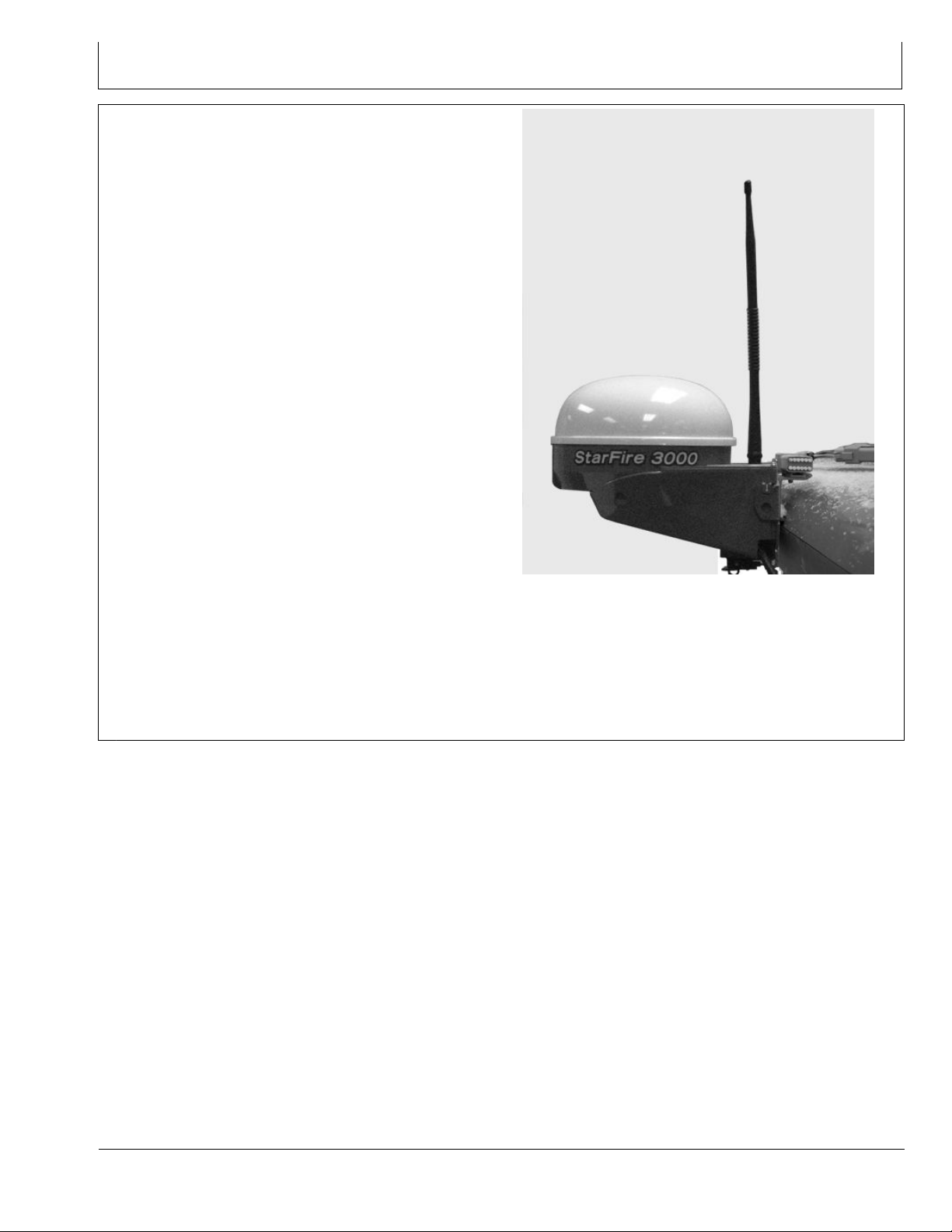
Receiver—On Vehicle
Position receiver with integrated RTK radio module is
located on top of machine. Position receiver receives
global positioning and differential correction signal through
a single receiver and integrates signal for use with system.
PC12123 —UN—11JUN09
The receiver has a dedicated operating mode (Vehicle
Mode). Refer to “Operating Mode—RTK” in “StarFire
3000” Section for setup of the receiver on vehicle.
IMPORTANT: The antenna must be installed before
the radio module is powered ON.
Avoid water intrusion by keeping the antenna
attached whenever possible.
Removing the antenna while transmitting
may damage the radio module.
NOTE: Actual receiver position may vary with the use of
an Original Shroud or Deluxe Shroud bracket.
Continued on next page JS56696,00007FF -19-15APR10-1/3
20-1
121511
PN=9
Page 10
900 MHz RTK—Base Station Setup
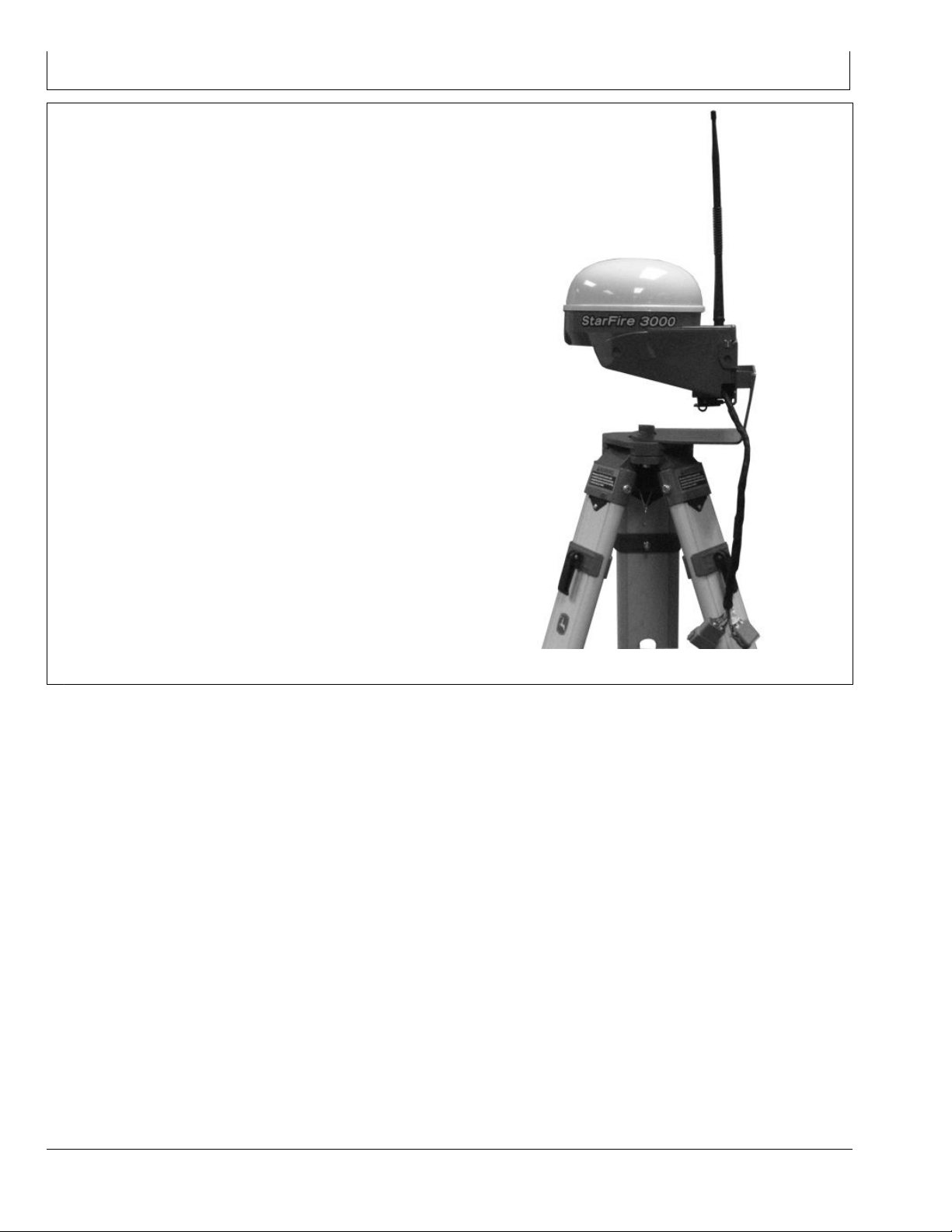
Receiver—On Base Station
The base station is the most critical part of an RTK system.
During installation, care must be taken to ensure the base
has problem-free operation. There are two issues that
are responsible for most problems with a base station:
Shading and Multipathing. If a base station experiences
one of these problems, it could be detrimental to your
RTK operation. Although it may not be possible to locate
a base station in an ideal location, this guide is aimed at
helping to dene the best option available.
Base station operating mode can be either Absolute
Survey Base Mode or Quick survey Base Mode. Refer to
“Operating Mode—RTK” in “StarFire 3000” Section for
setup of the receiver on base station.
Refer to “Base Station Operation and Setup” in “StarFire
3000” Section for proper use and setup of the base station.
PC12108 —UN—03JUN09
Continued on next page JS56696,00007FF -19-15APR10-2/3
20-2
121511
PN=10
Page 11
900 MHz RTK—Base Station Setup
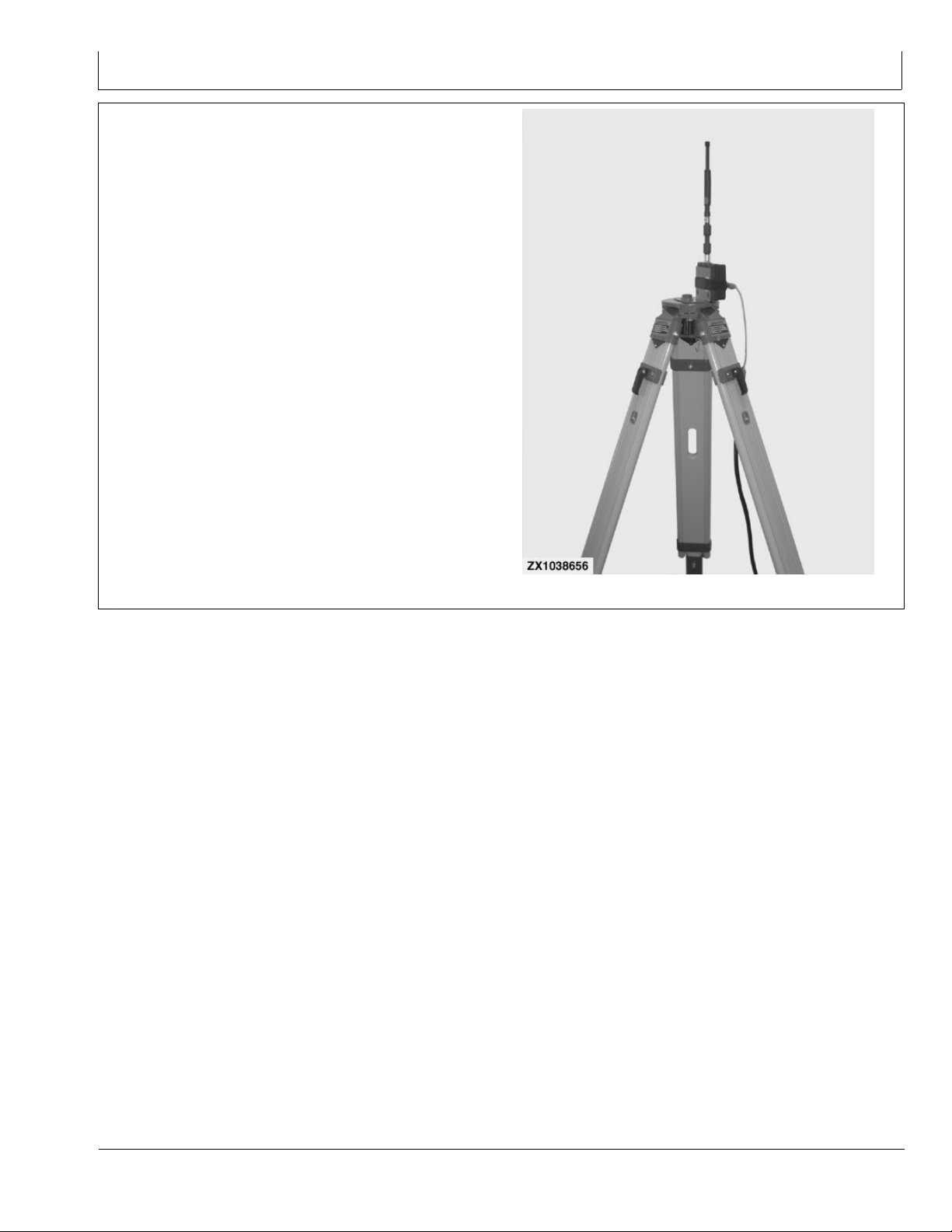
Repeater Radio
The radio can be congured to act separately as a
repeater. A repeater is required if obstructions (i.e. trees,
hills, etc.) exist between the base station and vehicle(s) or
if base station is too far away from the vehicles.
A repeater consists of:
Radio (congured as a repeater)
•
Harness
•
Mounting Bracket
•
12 Volt Power Source
•
Tripod or wall mount cradle
•
IMPORTANT: A repeater can only be used to repeat
a signal from a base station to a vehicle.
Therefore, a repeater cannot be used in a
''daisy chain,'' repeating the signal from
one repeater to another.
Refer to “Repeater—RTK” in “StarFire 3000” Section to
properly congure radio as repeater.
ZX1038656 —UN—06FEB06
JS56696,00007FF -19-15APR10-3/3
20-3
121511
PN=11
Page 12

900 MHz RTK—Base Station Setup
Installation of the RTK radio and antenna
After installing the base station receiver, installing the
radio in a location to best maximize the output can be
a challenge. Below are four options currently available
through John Deere.
Leave the RTK radio in its original conguration
•
attached directly behind the base station receiver.
- Use a repeater as part of the base station. Install a
radio with the base station receiver.
- Install a Repeater radio (available through whole
goods or parts) in an elevated location.
The base station will then send the RTK data to the
•
repeater and the repeater will then transmit that data
out to the repeater , and vehicle on the network. This
will eliminate other repeaters in the system.
NOTE: Additional repeaters cannot be run off of the
central repeater. In areas with heavy foliage or
uneven terrain, this setup method is not advised.
Use 92 m (300 ft) extension harness PF80821 to move
•
the radio from the back of the base station receiver to
an elevated position.
NOTE: Use extension harness PF80821.
Use installation instructions provided with
extension harness PF80821 to ensure proper
grounding and wiring according to the installation
instructions. This harness has built in protection
for both the radio and receiver for unwanted static
electricity developed on the harness.
Attach the RTK radio in a safe and unobstructed
•
location, Connect radio and antenna using coaxial cable.
IMPORTANT: The antenna must be installed before
the radio module is powered ON.
Avoid water intrusion by keeping the antenna
attached to the radio whenever possible.
Removing the antenna while transmitting
may damage the radio module.
IMPORTANT: If using a coaxial cable between the
radio and antenna, use the lowest-loss cable
available to avoid RTK radio link range issues.
NOTE: When using this option, it may be
necessary to install a higher-gain antenna
to compensate for loss.
NOTE: Old antennas from past receivers are not
compatible with the StarFire 3000 receiver.
Always mount the radio antenna vertically to make sure
that the RTK signal is radiating outwards. If the antenna is
at an angle, it may cause the data received at the vehicle
to be lower than expected.
DK01672,0000208 -19-01DEC11-1/1
20-4
121511
PN=12
Page 13
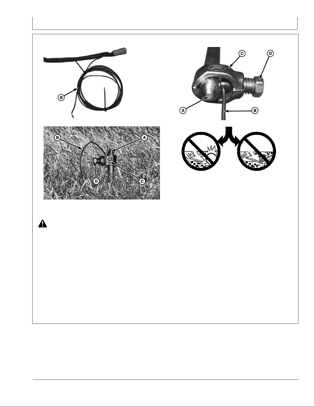
Attaching RTK Harness
900 MHz RTK—Base Station Setup
A—Rod
B—Grounding Wire C—Collar D—Screw
CAUTION: Avoid serious injury or death to you or
others. Contact your local utility companies to
determine the location of gas, electric, or water
lines. Placement of grounding rod must be a safe
distance away from pipelines and cables.
IMPORTANT: Carefully choose location of rod so that
it is away from paths where it could damage
equipment or be damaged by equipment.
DO NOT route RTK Extension harness along any
other power sources. Keep harness at least 2m
(6 ft) away from any other AC power lines.
1. Attach harness between radio and receiver.
PC8570 —UN—14JUL05
PC8571 —UN—14JUL05
3. Route grounding wire (B) from harness to rod.
Grounding wire may be extended if necessary to
reach rod.
4. Remove insulation from end of grounding wire.
5. Place collar (C) over end of rod.
6. Place grounding wire between rod and screw (D).
7. Tighten screw.
8. Restrain harness to supporting structures as
necessary to keep them away from equipment,
damage, and to reduce wire strain.
PC8568 —UN—14JUL05
PC8569 —UN—14JUL05
2. Carefully determine placement of rod (A) a safe
distance away from pipelines and cables. Drive into
ground leaving one end above surface.
20-5
JS56696,0000801 -19-15APR10-1/1
121511
PN=13
Page 14
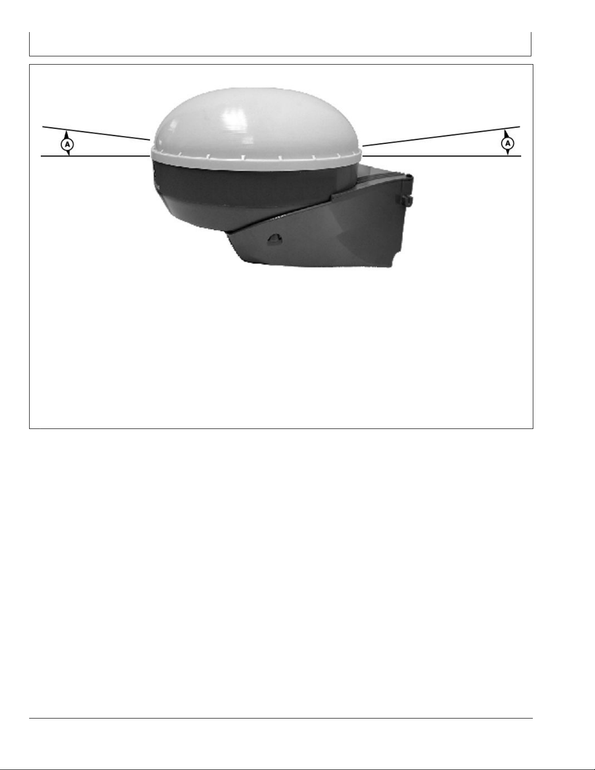
RTK Network Base Station Setup
A—5 Degrees Off the Horizon
(Mask)
900 MHz RTK—Base Station Setup
PC12154 —UN—14JUL09
Installing and operation of the Base Station Receiver.
The base station is the most critical part of the RTK
operation. Setting up a base station correctly is vital to the
operation of the RTK system. If the Base Station Receiver
is setup in a questionable location, the receiver could
have two separate issues; Shading and Multipathing.
Shading:
To ensure proper operation of a RTK base station, the
GPS Receiver must have a clear view of the sky in all
directions above 5 degrees off the horizon. Both the base
receiver and the vehicle receiver will use any satellites
that are above 5 degrees off the horizon. If a base station
receiver cannot use a satellite above 5 degrees, then all
vehicles operating on that base station also cannot use
that blocked satellite. This is called Shading of the base
station. If enough shading occurs, the RTK system may
become inaccurate. Many things can cause shading, such
as buildings, towers, poles, and grain legs.
Continued on next page DK01672,0000209 -19-01DEC11-1/3
20-6
121511
PN=14
Page 15
900 MHz RTK—Base Station Setup
When selecting a base station location, there are three
main points to look for: rigidity, good view of the sky,
and few reective objects. The base station provides
corrections to the vehicle receiver based on the xed
known position which is surveyed in with an absolute
survey or quick survey. Any motion of the base station
receiver will translate directly to the vehicle position.
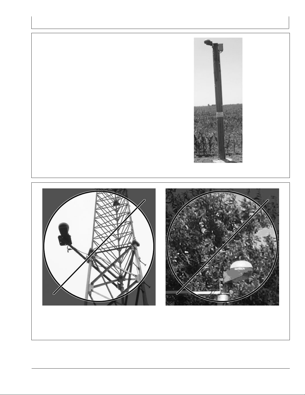
Mount the base station on a rigid structure, such as the
pole in the photo. When mounting on a structure such as
a building, the receiver should generally be installed 2
meters above the highest point.
PC12104 —UN—03JUN09
Receiver on Rigid Pole
DK01672,0000209 -19-01DEC11-2/3
Receiver on Radio Tower
Since GPS satellites orbit the earth, the base station
needs to have a clear view of the sky in all directions
above a 5 degree mask angle. Base stations with a good
20-7
PC12105 —UN—03JUN09
Receiver Next to Trees
view of the sky are much more reliable than those with
shading. Installing the receiver on the side of radio towers
or next to trees is not recommended.
DK01672,0000209 -19-01DEC11-3/3
PC12106 —UN—03JUN09
121511
PN=15
Page 16
900 MHz RTK—Base Station Setup
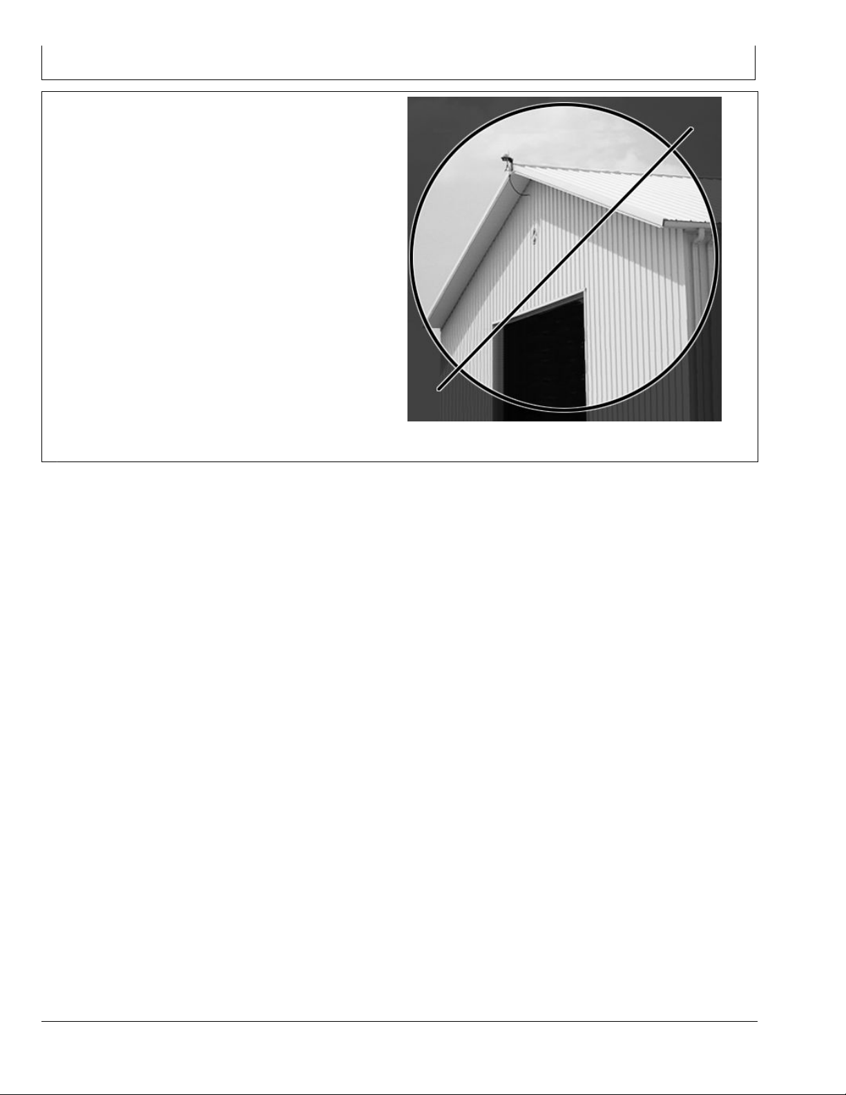
Multipathing
Signal reections are another important error source
for base stations that should be minimized. Reected
signals also reach the base station receiver and make
the satellite range measurement longer. Reections can
even interfere with the direct signal enough so that the
receiver will temporarily lose lock on the satellite. Metal
buildings, chain-link fences, and bodies of water are all
good reectors that can make a base station less reliable.
Take care to place your base station receiver far away
from strong reectors for reliable base station operation.
A base station should have a continuous 12V power
source such as an AC/DC converter to power the base
station. A battery back-up is recommended to keep the
base station running in the case of power outages for
dependable operation.
NOTE: The AC/DC converter is not supplied
by John Deere.
PC12107 —UN—03JUN09
Reection off Metal Building
DK01672,00001C2 -19-11NOV11-1/1
20-8
121511
PN=16
Page 17
PDOP Denition
900 MHz RTK—Base Station Setup
PC9548 —UN—06NOV06
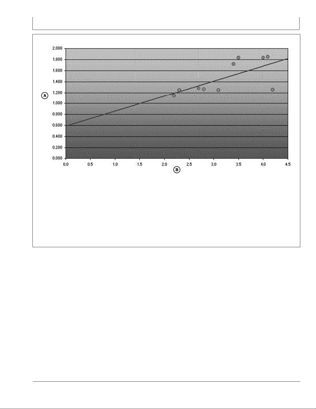
A—Horizontal Precision (m) B—Maximum PDOP Value
The Position Dilution of Precision (PDOP) is likely one
of the most critical GPS AutoTrac values to monitor.
As the PDOP value increases, both the horizontal and
vertical precision (guidance accuracy) of your data points
decreases.
To help illustrate this relationship, please review the
graph, which plots the PDOP value against the horizontal
precision points collected on and around the University of
Montana campus. Ten locations were collected to serve
as ground control points to register an April 4, 1999 aerial
photograph of the University area. You can see that
as the PDOP value climbs from a minimum of 1.15 to a
maximum of approximately 4.5, the horizontal precision
and accuracy decreases from about 1.15 meters to about
1.9 meters. PDOP values below 7 are generally required
to collect data at a 1 meter accuracy range (as determined
by the PDOP mask set on your data logger) and any value
below 3.5 is considered in-range for AutoTrac applications.
Continued on next page DK01672,00001E2 -19-15NOV11-1/2
20-9
121511
PN=17
Page 18
900 MHz RTK—Base Station Setup
GOOD
Keep in mind that PDOP (Position Dilution of Precision)
is the measure of the geometrical strength of the GPS
satellite conguration. As a general rule, any PDOP value
below 3.5 is acceptable to use while operating AutoTrac
but, the lower the number, the more precise the steering
accuracy will be.
PC9550 —UN—06NOV06
BAD
During vehicle operation, the PDOP can be viewed
under the StarFire information pages in both the Original
GreenStar Display, 2600 Display, and 2630 Display.
DK01672,00001E2 -19-15NOV11-2/2
PC9549 —UN—06NOV06
20-10
121511
PN=18
Page 19

PDOP Operating Values
900 MHz RTK—Base Station Setup
StarFire 3000 - Satellites
A—SkyPlot tab B—Graph tab C—PDOP
PDOP operating values should remain BELOW 3.5
DURING ALL AUTOTRAC OPERATIONS, especially RTK
high precision operations. As the value of PDOP rises
above 3.5, position accuracy will be compromised.
high PDOP values (4 to 20+) will be experienced for
upwards of 15 minutes (under normal conditions).
It is important to monitor PDOP along with GPS signal
quality while performing eld operations.
As a rule, when the GPS receiver is warming up from
being in a powered off state and gathering satellite signals
PC12061 —UN—12MAY09
JS56696,0000805 -19-15APR10-1/1
20-11
121511
PN=19
Page 20

900 MHz RTK—Base Station Setup
StarFire Signal Monitoring System
A—Info tab
B—Setup tab
C—Activations tab
D—Serial Port tab
E—Position Mode
StarFire 3000 Main
F— Degrees/Minutes/Seconds to
Decimal Toggle
G—Latitude
H—Longitude
I— Altitude
J— GPS Course
K—GPS Speed
L— Accuracy
M—GPS Signal
N—Differential Signal
O—Roll Angle
Continued on next page JS56696,0000806 -19-15APR10-1/5
P—Pitch Angle
Q—Yaw Rate
PC12043 —UN—08MAY09
20-12
121511
PN=20
Page 21

900 MHz RTK—Base Station Setup
GreenStar2 Pro - Guidance
A—View
B—Guidance Settings C—ShiftTrack Settings D—Signal Quality
The GS2 alerts the operator when the current StarFire
signal is not accurate. There are three levels of this
alarm system (Normal, Marginal, and Poor). The levels
are determined both by the StarFire Receiver's PDOP
value and the number of satellites being tracked. It is
recommend that if the StarFire receiver is being used
in high accuracy operations that care be taken when
the StarFire Signal Monitoring system indicates that
the current status is Marginal or Poor, as accuracy
degradation may occur.
PC9554 —UN—10OCT07
NOTE: Operating in RTK or RTK-X, both PDOP and
“Number of Satellites” are used to determine
the level of alarm.
Operating at a signal level less than RTK (SF2,
SF1, WAAS, ect.) only PDOP will be used to
determine the level of alarm.
Continued on next page JS56696,0000806 -19-15APR10-2/5
20-13
121511
PN=21
Page 22

900 MHz RTK—Base Station Setup
Normal
Green Bar
•
Normal Operating Range
•
Acceptable range for high accuracy operations
•
PDOP value: 0 - 3.5
•
6 or more satellites in solution
•
Marginal
Orange bar with permanent operator alert sign
•
Marginal operating range
•
Moderate risk of accuracy degradation
•
PDOP value: 3.5 - 4.5
•
5 satellites in solution
•
Poor
PC9387 —UN—17OCT06
Normal
JS56696,0000806 -19-15APR10-3/5
PC9388 —UN—17OCT07
Marginal
JS56696,0000806 -19-15APR10-4/5
PC9388 —UN—17OCT07
Red bar and ashing operator alert sign
•
Poor operating range
•
Signicant risk of accuracy degradation - high accuracy
•
operations are not advised
PDOP value greater than 4.6
•
4 satellites or less in solution
•
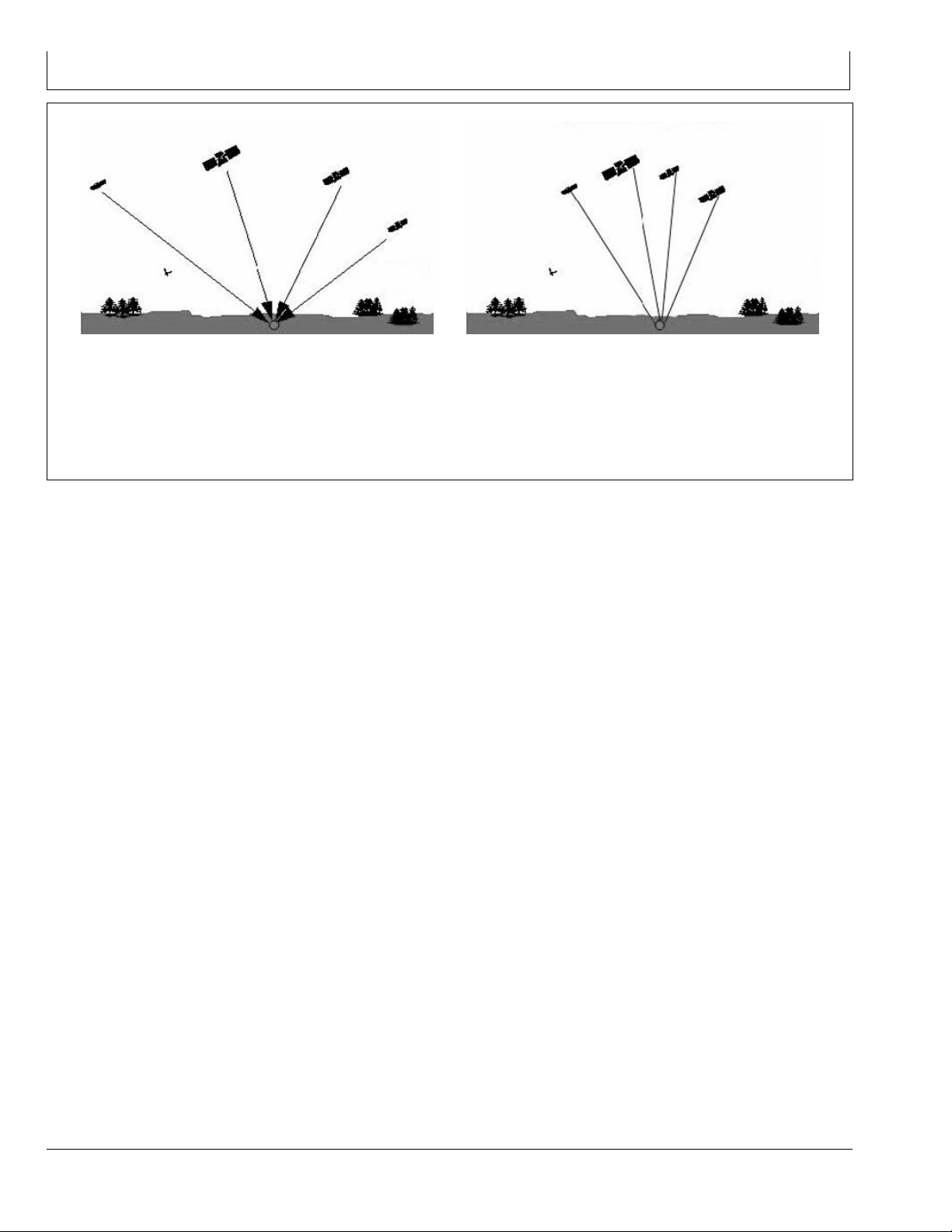
Antenna Height
RTK Shared Base Station: Antenna Height
In order to maintain a good RTK Radio link, the antenna
must be mounted high enough to radiate over the earth’s
curvature and any obstacles. As shown in the gure, the
curve of the earth can block the signal from the RTK link.
If the radiating base station radio antenna is mounted too
low, the broadcasting range will be drastically reduced.
Poor
JS56696,0000806 -19-15APR10-5/5
PC9393 —UN—23OCT06
JS56696,0000807 -19-15APR10-1/1
20-14
121511
PN=22
Page 23

900 MHz RTK—Base Station Setup
Specic Tower Setup Information
It is recommended that the receiver be, at minimum, 9.1
m (30 ft) away from the tower to prevent both Shading
and Multipathing. This distance may vary depending on
the frame design of the tower or structure that you are
mounting it around.
When using the 91 m (300 ft) extension harness, do not
cut the harness to the length needed. This harness has
built in voltage protection and is shielded. Cutting the
harness will limit the effectiveness of the harness and will
cause failures of either the radio or the receiver due to
static electricity build up on the harness. This harness
Utilizing The RTK Extension Harness
This base station setup allows you to mount the receiver
at a secure location and mounting the radio, with antenna,
to an elevated position, and utilizing 91 m (300 ft) of
RS232 cable between the receiver and radio.
A—Radio mounted on tower
B—Base Station Receiver
was built to be buried underground, so it is suggested to
bury all extra harness underground to protect the harness.
After deciding what structure that you will be mounting
your base station on, there are ve different ways to set
up your base station.
Utilizing Both The 91 m (300 ft) RTK Extension Harness
•
And Low Loss Coax Cable
Utilizing The RTK Extension Harness
•
Utilizing A Repeater
•
Utilizing Just Low Loss Coax Cable
•
Leaving The Radio And Receiver As A Single Unit
•
JS56696,0000808 -19-15APR10-1/1
Utilizing Just Low Loss Coax Cable
This base station set up leaves the receiver and radio in a
secure location and using low loss coax cable running to
the antenna at an elevated position.
A—Receiver and Radio
B—Coax Cable
PC8762 —UN—16SEP05
JS56696,000080A -19-15APR10-1/1
PC8763 —UN—16SEP05
JS56696,000080C -19-15APR10-1/1
20-15
121511
PN=23
Page 24

900 MHz RTK—Base Station Setup
Utilizing Both The 91 m (300 ft) RTK Extension Harness And Low Loss Coax Cable
A—91.4 m (300 ft) RS232 Cable
from receiver
B—Coax cable connection from
antenna
This base station setup allows the placement of the
receiver to be up to 91.4 m (300 ft) away from the radio,
giving the base station an absolute clear view of the sky.
The radio, usually installed in a secure location at the
bottom of a tower, is then connected to low loss coax that
is ran up the tower to the antenna.
A—Antenna
B—Low-Loss Coax Cable
C—91.4 m (300 ft) RS232 Cable
PC9555 —UN—06NOV06
C—Coax running up tower to
antenna
PC9556 —UN—06NOV06
D—Coax looped under electrical
box
JS56696,0000809 -19-15APR10-1/2
20-16
PC9557 —UN—06NOV06
JS56696,0000809 -19-15APR10-2/2
121511
PN=24
Page 25

900 MHz RTK—Base Station Setup
Utilizing A Repeater
This base station setup allows the placement of the
receiver and radio in a location with no obstructions.
A repeater, with its own power source, is placed at an
elevated location. The base station radio sends its signal
up to the repeater and the repeater then sends out the
signal.
NOTE: With this type of base station setup, no other
repeaters can be used with the base station.
PC8761 —UN—16SEP05
JS56696,000080B -19-15APR10-1/1
Leaving The Radio And Receiver As A Single Unit
This base station setup keeps the receiver and radio as a
single unit usually mounted in an elevated location.
IMPORTANT: Receiver must have a clear view of the
sky and must be free of Multipathing.
The receiver must not move. Any movement
of the receiver will result in movement of
the vehicle receivers.
PC9558 —UN—06NOV06
JS56696,000080D -19-15APR10-1/1
20-17
121511
PN=25
Page 26

900 MHz RTK—GS2 Display
RTK softkey
Allows for setup and display of RTK information
Operating Mode
•
RTK Network Conguration
•
Base Station Data
•
Radio Data
•
RTK can be operated in six modes
OFF
•
Vehicle
•
Vehicle Repeater
•
Repeater
•
Quick Survey Base
•
Absolute Base
•
IMPORTANT: Anytime the radio is disconnected,
power must be cycled at the GPS receiver
before continuing.
Vehicle Mode Select for receiver on vehicle.
Vehicle Repeater Mode Allows for the vehicle to accept
and repeat RTK corrections.
PC8663 —UN—05AUG05
PC12042 —UN—08MAY09
PC8681 —UN—05AUG05
of corrected position. For this reason, it is important to
mount receiver to a xed position like a building or post
mounted in concrete.
MENU button
StarFire 3000 button
RTK softkey
Repeater Mode A repeater is required if obstructions (i.e
trees, hill, etc.) exist between base station and vehicle(s).
Quick Survey Base Mode Select Quick Survey Base
Mode if exact location of guidance tracks will not be used
for future applications. If Quick Survey Base Mode is used
to establish rows or paths used at a later date, location or
Track 0 must be stored using Current Track 0 in Guidance
Setup – Set Track 0. When Track 0 is recalled, a one-time
use of Shift Track feature is needed to align vehicle on
previous tracks. See Setup Quick Survey Base Mode
section.
NOTE: Quick Survey Base Mode requires a 15 minute self
survey to be conducted on location before rst use.
Absolute Survey Base Mode Select Absolute Survey
Base Mode if exact location of guidance tracks need
to be stored for future guidance applications without
relying on visual reference for track position to align
using Shift Track feature. Track 0 must be stored using
Current Track 0 in Guidance Setup – Set Track 0 in order
to follow previously used tracks. Absolute Base Mode
requires 24-hour self survey to be conducted on location
before rst use. After survey is completed, base station
will then transmit corrections. If base station is moved to
another position and then returned to original surveyed
position, it is important that base station is mounted in
exact same position. Any difference between original
surveyed position and mounted position will result in offset
OFF Mode This mode disables all RTK functionality in
receiver. RTK Operating Mode must be OFF for normal
SF1 or SF2 operation on SF2-licensed receiver.
NOTE: Radio can be congured to act separately as
repeater. A repeater is required if obstructions
(i.e. trees, hills, etc) exist between base
station and vehicle(s).
A repeater consists of:
Radio (congured as a repeater)
•
Harness
•
Mounting Bracket
•
12 volt Power Source
•
To congure radio as repeater:
Select: MENU button >> StarFire 3000 button >> RTK
softkey
Select RTK Operating Mode (Vehicle, Quick Survey Base
or Absolute Base).
NOTE: A radio can be congured as a repeater from
any RTK Operating Mode.
1. Disconnect original radio from receiver.
2. Connect radio to be congured to receiver RTK
harness.
3. Check that the radio serial number and software
version are displayed.
Continued on next page DK01672,00001C1 -19-11NOV11-1/2
25-1
121511
PN=26
Page 27

900 MHz RTK—GS2 Display
4. Check that base station, vehicle, and repeater have
same Frequency, Network ID and Radio Channel.
5. Select START button located under Congure
Repeater Radio.
6. Radio will congure as repeater.
7. Disconnect repeater radio from receiver and wiring
harness.
8. Reconnect original radio.
DK01672,00001C1 -19-11NOV11-2/2
25-2
121511
PN=27
Page 28

Vehicle
900 MHz RTK—GS2 Display
StarFire - RTK
A—RTK Network Conguration
B—Congure button
C—Operating Mode
D—Radio Channel
E—Network ID
F— Base Station Data
G—Status
H—Satellite Corrections
I— Location Number
K—Distance
IMPORTANT: Base station receiver and vehicle
receiver must be setup before operating
RTK. See RTK Setup sections.
Select: MENU button >> StarFire 3000 button >> RTK
softkey >> CONFIGURE button >> OPERATING MODE
drop down box >> VEHICLE
When vehicle receiver is powered-up, No GPS, No Diff
will be displayed on Guidance View or home page screen
until an initial position is determined. When base station
transmits correction signal, 3D RTK will be displayed.
NOTE: If communication loss occurs WITHIN rst
hour of base station operation, Extend Mode will
provide RTK accuracy for two minutes.
If Communication loss occurs AFTER rst hour of
base station operation, Extend Mode will provide
RTK accuracy for 15 minutes.
L— Direction (degrees)
M—Base Battery (V)
N—Radio Data
O—Percent Received
P—Noise Level
Q—Refresh button
R—Radio Connection
S—Radio Connection Toggle
button
Extend Mode (RTK-X) If communication between base
station and vehicle radio is lost for more than 10 seconds,
vehicle receiver will automatically switch to Extend Mode
and will maintain RTK accuracy for a period of time. If the
base station has been navigating in SF2 for less than 1
hour, the RTK-X timeout can vary from 2 minutes to 15
minutes depending on the accuracy of the base station’s
SF2 solution. As the base station solution pulls in, more
RTK-X time will be allowed. After the base station has
been navigating in SF2 mode for 1 hour, the vehicle
receiver will have 15 minutes of RTK-X after the radio
communication is lost. If base station communication is
not re-established after Extend period, receiver will default
to WAAS in North America, or NO DIFF where WAAS
is not available. To re-establish communication, move
vehicle to a location where line of sight to base station can
be established.
Continued on next page DK01672,00001BE -19-11NOV11-1/2
PC12058 —UN—12MAY09
25-3
121511
PN=28
Page 29

900 MHz RTK—GS2 Display
Base Station Data (Information)
Operator can view the following:
Base Station Data in information that will be displayed
when in Quick survey Base or Absolute Base Mode.
Status
•
- OK—Base Station is transmitting correction.
- No Stored Base—24 hour self survey is required for
current location.
- Initializing—Receiver is initializing radio, acquiring
GPS signal.
- Self Survey—24 hour self survey in progress.
Sat. Corrections – Indicates number of GPS satellites
•
for which base station is transmitting correction.
Distance – Difference between base station location
•
(known position) and location indicated by uncorrected
GPS. Displayed in miles (kilometers).
Direction – Direction from base station location (known
•
position) to location indicated by uncorrected GPS.
Displayed in degrees with true North as 0 degrees.
Base Battery – Base Station voltage. Displayed in volts.
•
Radio Data and Connection
Signal Level – Level of signal which is detected at radio.
Select Refresh button to refresh signal level.
Vehicle Mode – Base Station Data
NOTE: Information that will be displayed when
in Vehicle Mode.
Status
•
- OK – Base Station is transmitting correction.
- No Stored Base – 24 hour self survey is required for
current location.
- Initializing – Receiver is initializing radio, acquiring
GPS signal.
- Self Survey – 24 hour self survey in progress.
- No Signal – Vehicle RTK radio is not receiving signal
from base station.
Sat. Corrections – Indicates number of GPS satellites
•
for which base station is transmitting correction.
Distance – Difference from base station to vehicle
•
receiver. Displayed in miles (kilometers).
Direction – Direction in degrees to base station.
•
Displayed in degrees with true North as 0 degrees.
Base Battery – Base Station voltage. Displayed in volts.
•
Radio Data and Connection
Signal Level – Level of signal which is detected at radio.
•
Press Refresh button to refresh signal level.
Data Received (%) – Percent of received correction to
•
vehicle from base station.
Indicates source of correction. If there is no correction,
this will toggle between base and repeater. There is also a
TOGGLE button for manual toggle between two sources.
DK01672,00001BE -19-11NOV11-2/2
25-4
121511
PN=29
Page 30

Vehicle Repeater
900 MHz RTK—GS2 Display
PC9148 —UN—20APR06
Press: MENU button >> StarFire 3000 button >> RTK
Softkey
Select “Vehicle Repeater” from Operating Mode list box.
In this mode the RTK vehicle radio not only receives
messages but also rebroadcasts them (similar to a RTK
repeater) to other RTK vehicles in close proximity.
NOTE: Vehicle Repeater is identical to the Vehicle
mode with the addition of having the radio
rebroadcast the RTK messages.
The Vehicle Repeater mode allows an RTK vehicle
to function normally as an RTK vehicle while also
Quick Survey Mode
NOTE: Display is not required after base station receiver
has been congured to operate in Quick Survey
Mode and RTK Radio Frequency, Network ID
and Radio Channel have been set.
Connect display to base station.
Press: MENU button >> StarFire 3000 button >> RTK
softkey
Select Quick Survey Base from Operating Mode list box.
NOTE: Quick Survey Base Mode allows base
station to broadcast corrections after receiver
calculates GPS position.
transmitting the base correction signal to another RTK
vehicle that does not have line-of-sight to the base station.
The ‘Vehicle Repeater’ needs to be between the base
station and the ‘Vehicle’. The ‘Vehicle Repeater’ must be
able to communicate with the base station. The ‘Vehicle’
must then have either line of sight communication to the
base station or ‘Vehicle Repeater’.
IMPORTANT: There should be only ONE Vehicle
Repeater or Repeater in the same vicinity
with the same Network ID.
JS56696,00007ED -19-15APR10-1/1
If power is removed from base station (but not moved)
power can be restored and same base station position
will be used for corrections. If previously used Track 0 is
recalled, Shift Track may not be needed.
If power is removed and base station is moved a new
position will be calculated when power is restored. If
previously used Track 0 is recalled, Shift Track will have
to be used to center Track 0 on previous vehicle track.
JS56696,00007EE -19-15APR10-1/1
25-5
121511
PN=30
Page 31

900 MHz RTK—GS2 Display
Absolute Base Mode
IMPORTANT: Absolute Base Mode requires base
receiver to be mounted in a rigid position.
Tripod is not recommended.
NOTE: Display is not required after base station receiver
has been congured to operate in Absolute Survey
Base Mode and RTK Radio Frequency, Network
ID and Radio Channel have been set.
Connect Display to Base Station.
Press: MENU >> StarFire 3000 button >> RTK softkey
Select Congure button.
Select Absolute Base from Operating Mode drop-down
and set other settings.
After radio is congured, select the Edit Store RTK Base
button on lower right.
A 24-hour survey has to be performed and saved to a
RTK Base Location (1-200).
NOTE: Enter unique location number each time base
station is moved to new mounting location
(i.e. location 1 = West 40, location 2 = Farm
Shop). Edit Stored RTK Base: Allows operator
to setup Absolute Base Station Locations and
conduct 24-hour survey or enter in known location
coordinates. Unknown Coordinates: Press START
button located under Edit Stored RTK Base.
After (24 hour) self survey is complete, base
station coordinates will automatically be stored
and associated with base location number (1 -
200). Verify base station coordinates, Press START
button located under Edit Stored RTK Base while in
Absolute Base operating mode and choose base
location from base location drop-down box.
PC12059 —UN—12MAY09
Survey RTK Base Location
A—RTK Base Station
B—Base Location
C—Base Latitude
Continued on next page JS56696,00007EF -19-15APR10-1/2
D—Base Longitude
E—Base Altitude
F— Survey RTK Base Location
Start button
25-6
121511
PN=31
Page 32

900 MHz RTK—GS2 Display
Start 24 hour Self Survey
1. Press START button located under Survey RTK Base
Location.
2. Select Storage location from drop-down box (1 - 200)
3. Press START button (Starts 24 hour survey)
NOTE: Display can be removed while survey
is in progress.
After 24 hour survey is complete, base station will
automatically store surveyed coordinates and begin
transmitting corrections.
IMPORTANT: Manually record coordinates
and elevation and store in safe location.
These coordinates may be used to enter
previously surveyed base station location
into different receiver.
NOTE: Absolute Base Mode, coordinates may be
manually entered, if known from previous survey.
See Known Location section below.
PC12060 —UN—12MAY09
A—Select Storage Location
Known Location
Press START button located under Edit Stored RTK Base.
1. Select desired Base Location from drop-down box
(1-200)
2. Select Base Latitude – enter value (deg)
RTK Network Conguration
Radio Channel - RTK
NOTE: 14 Radio Channels are available. The
default Radio Channel is 1.
Press input box and enter value (1 - 14)
The Radio Channel may be changed if other RTK systems
are operating in area interference is causing decreased
base station communication performance.
3. Select Base Longitude – enter value (deg)
4. Select Base Altitude – enter value (ft)
5. Press ENTER button
JS56696,00007EF -19-15APR10-2/2
Network ID – RTK
NOTE: 4000 network ID’s are available, default ID is 1.
Press input box and enter value (1 - 4000)
Network ID for base station and vehicle receiver must
match. If more than one base station with same Network
ID numbers are within range, vehicle may lock on to either
one of the base stations. To prevent this from happening,
be sure to use unique network ID.
JS56696,00007F0 -19-15APR10-1/1
25-7
121511
PN=32
Page 33

Shared Base Station RTK Security
900 MHz RTK—GS2 Display
Shared Base Station (SBS) RTK Security is security
from unwanted users accessing a SBS RTK Network.
This security feature keeps unauthorized RTK vehicles
from accessing RTK corrections from the base station by
granting access to only those RTK vehicles on an access
list.
Compatibility
Base Station This security feature is not available on
original StarFire receivers being used as base stations.
RTK Vehicle It is compatible with original StarFire,
StarFire iTC, and StarFire 3000 receivers being used as
RTK vehicles.
Locating RTK Vehicle Receiver Serial Number
Software Versions Original StarFire Receiver – requires
software version of 7.50x or greater. StarFire iTC Receiver
– requires software version of 2.50x or greater.
Theory of Operation
The SBS RTK Network operator will enter into the base
station the serial numbers of RTK vehicle receivers that
are allowed to access the RTK corrections from that base
station. RTK vehicle serial numbers can be added and
removed at any time with an original GreenStar Display.
Only those rover serial numbers that are on the access
list on the base station receiver will be allowed to access
the RTK corrections from the base station.
JS56696,00007F1 -19-15APR10-1/1
25-8
121511
PN=33
Page 34

900 MHz RTK—GS2 Display
Shared Base Station Security—Setup
A—Rover Access List Setup
B—Rover Access List
C—Access List
D—Delete Rover
E—Delete List
F— Network Status
Network ID must be set between 4001 - 4090 to setup and
use SBS RTK security. When the network ID has been set
between 4001 - 4090, the SBS RTK Security softkey will
appear. Select this softkey to setup SBS RTK Security.
The SBS RTK Network operator will enter into the base
station the serial numbers of RTK vehicle receivers that
are allowed to access the RTK corrections from that base
station. RTK vehicle serial numbers can be added and
removed at any time. Only those rover serial numbers
that are on the access list on the base station receiver
will be allowed to access the RTK corrections from the
base station.
The StarFire 3000 - Shared Base Station Security screen
displays the RTK vehicle receiver serial number and
location it is stored. Only the serial numbers on the RAL
will be able to receive RTK corrections from the base
station when RTK Network is in SECURE mode.
Access List button (C) allows operator to input the serial
number of a receiver into the Access List.
PC11633 —UN—02FEB09
G—Toggle Button
H—Secure
I— Public
J— Previous Page
K—Next Page
PC11634 —UN—02FEB09
Delete Rover button (D) allows operator to remove a
receiver from the Access List.
Delete List button (E) allows operator to clear all inputted
receiver serial numbers from the Access List.
SBS Security can be operated in a Public or Secure mode.
Public – This mode does not restrict RTK vehicles from
•
receiving RTK corrections as long as they have the
same Network ID and Frequency as the base station.
This mode can be used when conducting a RTK demo
for potential customers or eld days.
Secure – This mode restricts RTK vehicles from
•
receiving RTK corrections if their serial numbers are
not entered into the RAL
Network Status (F) can be toggled between secure status
(H) and public status (I) using toggle button (G).
Continued on next page JS56696,00007F2 -19-15APR10-1/4
25-9
121511
PN=34
Page 35

900 MHz RTK—GS2 Display
Edit Rover Access List
1. Press Access List button on StarFire 3000 - Shared
Base Station Security screen.
2. Enter a rover number from the Rover Access List in
the entry box.
A—Rover Number (1-200)
3. Enter the serial number of the vehicle receiver to be
added to the Rover Access List in the entry box (A).
PC11635 —UN—02FEB09
Edit Rover Access List — Page 1
JS56696,00007F2 -19-15APR10-2/4
NOTE: The six digit hardware serial number can be
found on StarFire 3000 - Activations tab. Go to
the display in RTK vehicle and press MENU >>
StarFire 3000 >> Activations tab.
4. Press Enter button (B) to put receiver on the Rover
Access List.
5. Press Cancel button (C) to return to Rover Access List
without adding receiver to list.
A—Serial Number
B—Enter button
C—Cancel button
PC11637 —UN—02FEB09
Edit Rover Access List — Page 2
Continued on next page JS56696,00007F2 -19-15APR10-3/4
25-10
121511
PN=35
Page 36

900 MHz RTK—GS2 Display
If the serial number is already entered on the Rover
Access List, “Serial Number Already Exists.” will appear
on the screen.
RTK vehicle serial numbers can be deleted individually or
the entire list can be deleted.
Deleting individual entries:
1. Press Delete Rover button on StarFire 3000 - Shared
Base Station Security screen.
2. Enter rover number to be deleted from the list.
3. Press Delete button (C) to delete the rover from the list.
NOTE: Once a RTK vehicle serial number has been
deleted from the RAL, it will take approximately 18
minutes before the RTK vehicle will not longer be
able to operate off of that base station. During this
time the vehicle will transition into RTK extend.
NOTE: Verify rover has been deleted by viewing RAL list .
Deleting All Entries:
1. Press Delete List button on StarFire 3000 - Shared
Base Station Security screen.
PC9599 —UN—10NOV06
Duplicate Serial Number
A—Serial Number already
exists
2. Press Yes button (C) to delete all receivers from the
list..
NOTE: Press No button (B) to return to StarFire 3000
- Shared Base Station Security screen without
deleting all the receivers from the list.
A—Rover Number (1-200)
B—Cancel button
A—Are you sure you want to
delete entire Rover Access
List?
B—No
C—Delete button
C—Yes
PC11638 —UN—02FEB09
Delete Rover
PC9704 —UN—10NOV06
Delete Rover Access List
JS56696,00007F2 -19-15APR10-4/4
25-11
121511
PN=36
Page 37

900 MHz RTK—GS2 Display
RTK Vehicle Security Status
The RTK Vehicle (when operating off of a Secure Network
ID) will exist in one of the following RTK authorization
states: Unknown, Authorized, or Not Authorized.
Unknown – The RTK Vehicle StarFire upon power up
is in an “unknown” RTK authorization state. It will exist
in this state until communication with the base station is
established.
Authorized – Satellite Corrections on the RTK screen will
become greater than 0 when authorized.
Not Authorized – If not authorized occurs, an alarm will
appear on the screen.
JS56696,00007F3 -19-15APR10-1/1
25-12
121511
PN=37
Page 38

Radio Self Test
900 MHz RTK—GS2 Display
A—Readings tab
B—Data Logs tab
C—Over the Air tab
D—Radio Self Test tab
E—Radio Self Test Start button
F— Number of Updates
G—Radio Distance (m)
H—Number of Disconnects
IMPORTANT: The Radio Self Test needs to be
performed while the vehicle is not moving.
StarFire 3000 MUST be in RTK mode to
perform the radio self test.
NOTE: This is an average and putting the radio into
test mode will decrease this average until it is
put back into operational mode and allowed
to run for several minutes.
(G) Radio Distance — Distance from master to slave
radio.
(I) Radio Temperature — Internal temperature of the
radio, measured in degrees Celsius. Acceptable range of
values: -40 to +75 degrees Celsius.
(J) Antenna Reected Power — A voltage ratio used to
indicate problems with the antenna. Higher values (above
I— Radio Temperature
J— Antenna Reected Power
K—Transmit Current (mA)
L— Average Noise Level
M—Average Signal Level
N—Overall Receive Rate (%)
75) generally indicate issues with the antenna, possibly
an antenna that is broken.
(K) Transmit current — Amount of current consumed
during radio transmission. Acceptable operating range
is approximately 500 mA or less. Value can range any
where between 400 and 1000 mA.
(L) Average Noise level — Level of background noise
and interference seen at this radio. This is an average
reading taken at regular intervals by the radio. Putting the
radio in setup mode (which is what happens during the
radio test) will affect this reading. Average noise levels
would be somewhere between 15 and 30. Levels lower
than 15 are ok, but levels higher than 30 may start to
show signs of signal degradation.
Continued on next page DK01672,000020A -19-01DEC11-1/3
PC12048 —UN—11JUN09
25-13
121511
PN=38
Page 39

900 MHz RTK—GS2 Display
(M) Average signal level — Level of received signal that
this radio is seeing from the other radio transmitting to it.
This value should be at least a value of 15 higher than
the noise. If it is not, the link between the two radios is
probably not stable and reliable.
While the test is in progress the screen will read:
Radio Self Test in progress. . .
System is no longer in RTK mode.
Select END button to stop test.
(N) Overall receive rate —Percentage of data that was
successfully transmitted from master to slave radio on
the rst attempt. Values higher than 75 indicate a good
radio link.
DK01672,000020A -19-01DEC11-2/3
PC12047 —UN—12MAY09
DK01672,000020A -19-01DEC11-3/3
25-14
121511
PN=39
Page 40

900 MHz RTK—Original GreenStar Display
Operating Mode
IMPORTANT: Before starting SETUP procedures,
enter RTK activation number, see Enter
RTK Activation section.
NOTE: Radio can function in six different modes:
Vehicle
•
Quick Survey Base Mode
•
Absolute Base Mode
•
Vehicle Repeater
•
Repeater
•
Off
•
Screen: SETUP - RTK
Press: SETUP >> StarFire 3000 >> DIFF CORRECTION
SETUP >> RTK SETUP
Press letter button next to RTK OPERATION MODE and
toggle to desired selection.
Quick Survey Base Mode
Custom Operations
Tillage
Broad-acre Seeding Controlled Trafc
Suggested Base Station Mode For Operation
Vehicle Mode: Select for receiver on vehicle.
Vehicle Repeater Mode: This mode should only be used
in situations where multiple RTK vehicles are operating
in the same eld and due to the terrain, line-of-sight is
obstructed between one of the vehicles and the base
station.
Quick Survey Base Mode: Select if exact location
of guidance tracks do not need to be stored for future
applications. If Quick Survey Base Mode is used to
establish rows or paths that will be used at a later date,
location of Track 0 must be saved using Current Field
setting in Tracking Setup (see AutoTrac Operator's
Manual). When Current Field is recalled, a one-time use
of Shift Track feature will be needed to align vehicle on
previous tracks. See Setup Quick Survey Base Mode
section.
NOTE: Quick Survey Base Mode requires a 15 minute self
survey to be conducted on location before rst use.
Absolute Base Mode
Drip Tape
Strip Till
Row Crop
SETUP - RTK
A—RTK Operating Mode
B—RTK Radio Channel
Network ID
C——
D—Congure
E——
F— —
G—Return to Differential
Correction
Absolute Survey Base Mode: Select if exact location
of guidance tracks need to be stored for future guidance
applications without relying on visual reference for track
position to align using Shift Track feature. Track 0 must
be stored using Current Field in Tracking Setup in order
to follow previously used tracks. Absolute Base Mode
requires 24-hour self survey to be conducted on location
before rst use. After survey is completed, base station
will then transmit corrections. If base station is moved to
another position and then returned to original surveyed
position, it is very important that base station is mounted
in exact same position. Any difference between original
surveyed position and mounted position will result in offset
of corrected position. For this reason, it is important to
mount receiver to a xed position like building or post
mounted in concrete.
OFF Mode: This mode disables all RTK functionality in
receiver. RTK Operating Mode must be OFF for normal
SF2 operation on SF2 licensed receiver.
JS56696,00007F4 -19-15APR10-1/1
PC12080 —UN—13MAY09
30-1
121511
PN=40
Page 41

Vehicle Repeater
900 MHz RTK—Original GreenStar Display
PC9148 —UN—20APR06
Press: SETUP button >> StarFire 3000 >> Differential
Correction Setup (D) >> RTK Setup (A)
Toggle (A) button next to RTK Operating Mode until
“VEHICLE REPEATER” appears in the cell.
In this mode the RTK vehicle radio not only receives
messages but also rebroadcasts them (similar to a RTK
repeater) to other RTK vehicles in close proximity.
NOTE: Vehicle Repeater is identical to the Vehicle
mode with the addition of having the radio
rebroadcast the RTK messages.
The Vehicle Repeater mode allows an RTK vehicle
to function normally as an RTK vehicle while also
transmitting the base correction signal to another RTK
vehicle that does not have line-of-sight to the base station.
The ‘Vehicle Repeater’ needs to be between the base
station and the ‘Vehicle’. The ‘Vehicle Repeater’ must be
able to communicate with the base station. The ‘Vehicle’
must then have either line of sight communication to the
base station or ‘Vehicle Repeater’.
IMPORTANT: There should be only ONE Vehicle
Repeater or Repeater in the same vicinity
with the same Network ID.
JS56696,00007F5 -19-15APR10-1/1
30-2
121511
PN=41
Page 42

900 MHz RTK—Original GreenStar Display
Quick Survey Mode
NOTE: Display is not required after base station
receiver has been congured to operate in Quick
Survey Base Mode and RTK Frequency, Radio
Channel/Network ID have been set.
Connect display to base station..
Screen: SETUP - RTK
Press: SETUP >> StarFire 3000 >> DIFF CORRECTION
SETUP >> RTK SETUP
NOTE: Quick Survey Base Mode allows base
station to broadcast corrections after receiver
calculates GPS position.
If power is removed from base station (but not
moved) power can be restored and same base
station position will be used for corrections. If
previously used Track 0 is recalled in Parallel
Tracking/Auto Trac no Shift Track will be needed.
If power is removed and base station is moved, a new
position will be calculated when power is restored.
If previously used Track 0 is recalled in Parallel
Tracking/Auto Trac, use Shift Track. (See AutoTrac
Operator's Manual for Shift Track procedures.)
A—RTK Operating Mode
B—RTK Radio Channel
C—RTK Network ID
D——
PC12081 —UN—13MAY09
SETUP - RTK
E—Submit
F— —
G—Ruturn to RTK setup
Press letter button next to RTK OPERATING MODE and
toggle to QUICK SURVEY BASE MODE.
Absolute Mode
IMPORTANT: Absolute Base Mode requires base
receiver to be mounted in a rigid position.
Tripod is not recommended.
NOTE: Display is not required after base station
receiver has been congured to operate in
Absolute Survey Base Mode and RTK Radio
Channel/Network ID have been set.
Connect display to base station.
Screen: SETUP - RTK
Press: SETUP >> StarFire 3000 >> DIFF CORRECTION
SETUP >> RTK SETUP
Press letter button next to RTK OPERATING MODE and
toggle to ABSOLUTE SURVEY BASE MODE.
A—RTK Operating Mode
B—RTK Radio Channel
C—RTK Network ID
D——
E—Submit
F— —
G—Return to RTK Setup
JS56696,00007F6 -19-15APR10-1/1
PC12082 —UN—13MAY09
SETUP - RTK
Continued on next page JS56696,00007F7 -19-15APR10-1/3
30-3
121511
PN=42
Page 43

900 MHz RTK—Original GreenStar Display
Press letter button next to EDIT STORED RTK BASE
LOCATION (1-200) and SETUP - RTK screen will be
displayed.
NOTE: Enter unique location number each time base
station is moved to new mounting location (i.e.
location 1 = West 40, Field location 2 = North
80, Field location 3 = Farm shop).
Press letter button next to EDIT STORED RTK BASE
LOCATION (1-200) and enter desired location number.
A—Edit Stored RTK Base
Locations
B—Base Latitude
C—Base Longitude
D—Base Altitude
E——
F— Survey RTK Base Location
G—Return to RTK Setup
PC12083 —UN—13MAY09
SETUP - RTK
Continued on next page JS56696,00007F7 -19-15APR10-2/3
30-4
121511
PN=43
Page 44

900 MHz RTK—Original GreenStar Display
Not known coordinates: Press letter button next to
SURVEY RTK BASE LOCATION.
NOTE: After (24 hour) self survey is complete, base
station coordinates will automatically be stored and
associated with base location number (1-200). Verify
base station coordinates, see RTK INFO Pages.
Press letter button next to START SELF SURVEY. Display
can be removed while survey is in progress.
After 24 hour survey is complete, base station will
automatically store surveyed coordinates and begin
transmitting corrections. Manually record coordinates and
elevation and store in safe location. These coordinates
may be used to enter previously surveyed base station
location into different receiver.
NOTE: Absolute Base Mode, coordinates may be
manually entered, if known from previous survey.
Known Location: Press letter button next to BASE
(LATITUDE, LONGITUDE AND ALTITUDE) and enter
values for;
Base Lat (deg)
•
Base Lon (deg)
•
Base Alt (ft)
•
A—Survey
RTK Base Location
B—Select Storage Location
C—Position StarFire Receiver
Press Start Survey Below
D—Wait 24 hours
E—Base Location will be
Stored Automatically
F— Start Self Survey
G—Return to RTK Setup
A—Edit Stored RTK Base
Locations (1 - 200)
B—Base Latitude (deg)
C—Base Longitude (deg)
D—Base Altitude
PC12119 —UN—10JUN09
SETUP - RTK
E——
F— Survey RTK Base Location
G—Return to RTK Setup
PC12084 —UN—13MAY09
Setup - RTK
JS56696,00007F7 -19-15APR10-3/3
30-5
121511
PN=44
Page 45

900 MHz RTK—Original GreenStar Display
Shared Base Station RTK Security
SBS RTK Security is security from unwanted users
accessing a SBS RTK Network. This security feature
keeps unauthorized RTK vehicles from accessing RTK
corrections from the base station by granting access to
only those RTK vehicles on an access list.
Compatibility
Base Station This security feature is not available on
original StarFire receivers being used as base stations.
All setup must be performed with an Original GreenStar
Display.
Theory of Operation
The SBS RTK Network operator will enter into the base
station the serial numbers of RTK vehicle receivers that
are allowed to access the RTK corrections from that base
station. RTK vehicle serial numbers can be added and
removed at any time with an original GreenStar Display.
Only those rover serial numbers that are on the access
list on the base station receiver will be allowed to access
the RTK corrections from the base station.
Base Station Setup (Original GreenStar Display Only)
Screen: SETUP – RTK
Press: SETUP >> StarFire 3000 >> DIFF CORRECTION
SETUP >> RTK SETUP
NOTE: RTK base station must be operating in either
Quick Survey Base or Absolute Base Mode.
Enter a RTK Network ID between 4001 – 4090 (secure
Network ID range) in cell “C”.
RTK SECURE NETWORK will appear in cell “F”. Select
letter button “F”
Entering RTK vehicle (rover) serial numbers
Press letter button next to ROVER # (1-200) and enter
desired location number to store the RTK vehicle receiver
serial number. There are 200 slots available.
Press letter button next to ROVER HARDWARE SN and
enter serial number of RTK vehicle StarFire receiver.
NOTE: Original GreenStar Display - The six digit
hardware serial number can be found on INFO
– GPS – PAGE 3. Go to display in RTK vehicle:
Press INFO >> StarFire 3000 >> press PAGE
button until you reach PAGE 3.
NOTE: GreenStar 2100/2600 Display – The six
digit hardware serial number can be found
on StarFire 3000 - ACTIVATIONS tab. Go to
display in RTK vehicle: Press MENU >> StarFire
3000 >> ACTIVATIONS tab.
Rover Access List (RAL)
Screen: SETUP – RAL
Press: SETUP >> StarFire 3000 >> DIFF CORRECTION
SETUP >> RTK SETUP >> RTK SECURE NETWORK >>
DISPLAY AUTHORIZED LIST.
This displays the RTK vehicle receiver serial number and
location it is stored. Only the serial numbers on the RAL
will be able to receive RTK corrections from the base
station when RTK Network is in SECURE mode (see
Security Mode section below).
Press PAGE button to view subsequent pages of the RAL.
RTK Network Operating Mode
Screen: SETUP - RTK
Press: SETUP >> StarFire 3000 >> DIFF CORRECTION
SETUP >> RTK SETUP >> RTK SECURE NETWORK >>
RTK NETWORK IS CURRENTLY.
SBS Security can be operated in a Public or Secure mode.
Public – This mode does not restrict RTK vehicles from
•
receiving RTK corrections as long as they have the
same Network ID as the base station. This mode can
be used when conducting a RTK demo for potential
customers or eld days.
Secure – This mode restricts RTK vehicles from
•
receiving RTK corrections if their serial numbers are
not entered into the RAL
Deleting RAL
Screen: SETUP – RTK
Press: SETUP >> StarFire 3000 >> DIFF CORRECTION
SETUP >> RTK SETUP >> RTK SECURE NETWORK
>> DELETE ENTIRE LIST
RTK vehicle serial numbers can be deleted individually or
the entire list can be deleted.
Deleting individual entries:
Press letter button next to ROVER # (1-200). Enter the
vehicle receiver stored number that will be deleted (1-200).
Press letter button next to ROVER HARDWARE SN.
Enter a non-zero number (example: “1”) in place of the
serial number. The serial number has been removed from
the RAL.
NOTE: Once a RTK vehicle serial number has been
deleted from the RAL, it will take approximately 18
minutes before the RTK vehicle will no longer be
able to operate off of that base station. During this
time, the vehicle will transition into RTK extend.
Deleting entire list
Press letter button next to DELETE ENTIRE LIST.
Press letter button next to SUBMIT. It will change to
DELETED once the RAL has been deleted.
NOTE: Verify RAL has been deleted by viewing RAL list
(See Rover Access List section above).
Continued on next page DK01672,00001C0 -19-11NOV11-1/2
30-6
121511
PN=45
Page 46

900 MHz RTK—Original GreenStar Display
RTK Vehicle Setup
Original GreenStar Display
Screen: SETUP – RTK StarFire 3000
Press: SETUP >> StarFire 3000 >> DIFF CORRECTION
SETUP >> RTK SETUP >> VEHICLE
Original StarFire
Press: SETUP >> StarFire 3000 >> DIFF CORRECTION
SETUP >> RTK SETUP >> VEHICLE
NOTE: RTK vehicle can be operated in either Vehicle
or Vehicle Repeater Mode.
Enter the same RTK Network ID that the base station is
congured to.
RTK Vehicle Security Status
The RTK Vehicle (when operating off of a Secure Network
ID) will exist in one of the three following RTK authorization
states: Unknown, Authorized, or Not Authorized.
These states are displayed in one or more of the following
locations depending on display and receiver used:
(Displayed on INFO – GPS – PAGE 3 (StarFire 3000) or
PAGE 5 (Original StarFire) or Cell G on GSD or on Cell G
of the Original GreenStar Monitor on a GS2 display).
Unknown – The RTK Vehicle StarFire, upon power up,
is in an “unknown” RTK authorization state. It will exist
in this state until communication with the base station is
established. No message will be displayed in cell G of
the GreenStar Display.
Authorized – On power-up of a RTK Vehicle StarFire that
is properly congured and on the authorization list, the
message “RTK Network: Authorized” will be displayed
in cell G as soon as it establishes communication with
the secure RTK base station, and it determines that it is
authorized to receive RTK corrections.
Unauthorized – On power-up of a RTK Vehicle StarFire
that is properly congured, but the serial number has not
been entered into the base station RAL, the message
“RTK Network: Not Authorized” will be displayed in cell
G as soon as it establishes communication with the
secure RTK base station, and it determines that it is not
authorized to receive RTK corrections.
DK01672,00001C0 -19-11NOV11-2/2
Radio Channel
NOTE: 14 Radio Channels are available. The
default Radio Channel is 1
Screen: SETUP - RTK
Press: SETUP >> StarFire 3000 >> DIFF CORRECTION
SETUP >> RTK SETUP
The Radio Channel may be changed if other RTK
systems are operating in area and interference is causing
decreased base station communication performance.
A—RTK Operating Mode
B—RTK Radio Channel
C—RTK Network ID
D——
E—Submit
F— —
G—Return to RTK Setup
PC12085 —UN—13MAY09
SETUP - RTK
JS56696,00007F9 -19-15APR10-1/1
30-7
121511
PN=46
Page 47

900 MHz RTK—Original GreenStar Display
Network ID
NOTE: 4000 network ID's are available (default ID is 1).
Screen: SETUP - RTK
Press: SETUP >> StarFire 3000 >> DIFF CORRECTION
SETUP >> RTK SETUP
Network ID for base station and vehicle receiver must
match. If more than one base station with same Network
ID numbers are within range, vehicle may lock on to either
one of base stations. To prevent this from happening, be
sure to use unique network ID.
A—RTK Operating Mode
B—RTK Radio Channel
C—RTK Network ID
D——
E—Submit
F— —
G—Return to RTK Setup
Repeater
NOTE: The radio can be congured to act separately
as repeater. A repeater is required if obstructions
(i.e. trees, hills, etc.) exist between base
station and vehicle(s).
A repeater consists of:
Radio (congured as a repeater)
•
Harness
•
Mounting Bracket
•
12 Volt Power Source
•
To congure radio as repeater:
Screen: SETUP - RTK
Press: SETUP >> StarFire 3000 >> DIFF CORRECTION
SETUP >> RTK SETUP
1. Connect radio to receiver RTK harness.
PC12085 —UN—13MAY09
SETUP - RTK
JS56696,00007FA -19-15APR10-1/1
PC12086 —UN—13MAY09
SETUP - RTK
2. Check that receiver has GPS position calculated.
3. Check that base station, vehicle, and repeater have
same Frequency, Network ID and Radio Channel.
4. Toggle RTK Operating Mode to Repeater.
5. Radio will congure as repeater.
6. Disconnect repeater from receiver and wiring harness.
7. Reconnect original radio.
30-8
A—RTK Operating Mode
B—RTK Radio Channel
C—RTK Network ID
D——
8. Toggle Mode to Vehicle.
E—Submit
F— —
G—Return to RTK Setup
JS56696,00007FB -19-15APR10-1/1
121511
PN=47
Page 48

900 MHz RTK—Original GreenStar Display
RUN
JOHN DEERE
Tracking
A
B
C
D
E
F
G
PAGE 3
Track
No.
356-W
Error
(ft)
0.0
Mark
Point
Shift Track
3D
RTK-X
3
2
1
Operating Vehicle
IMPORTANT: The base station receiver and vehicle
receiver must be setup before operating RTK.
See Setup sections for setup procedures.
When vehicle receiver is powered-up, No GPS, No Diff
will be displayed on RUN - TRACKING - PAGE screen
until an initial position is determined. When base station
transmits correction signal, 3D RTK will be displayed on
RUN - TRACKING - PAGE screen.
NOTE: If communication loss is WITHIN rst hour of
base station operation, Extend Mode will provide
RTK accuracy for two minutes.
Communication loss AFTER rst hour of base
station operation, Extend Mode will provide
RTK accuracy for 15 minutes.
A——
B——
C——
D——
E—Track Number, Error
F— —
G—3D RTK, Shift Track, Mark
Point
Extend Mode (RTK-X): If communication between base
station and vehicle radio is lost for more than 10 seconds,
vehicle receiver will automatically switch to Extend Mode
and will maintain RTK accuracy for a period of time.
RTK-X will be available for approximately 2 to 15 minutes
if base station has been powered up for less than 1 hour.
If base station communication is not re-established after
Extend period, receiver will default to WAAS, or NO DIFF
where WAAS is not available.
A——
B——
C——
D——
E—Track Number, Error
F— —
G—3D RTK, Shift Track, Mark
Point
PC9562 —UN—12MAY09
RUN - Tracking - PAGE 3
JS56696,00007FC -19-15APR10-1/2
PC9565 —UN—06NOV06
30-9
RUN - Tracking - PAGE 3
JS56696,00007FC -19-15APR10-2/2
121511
PN=48
Page 49

900 MHz RTK—Original GreenStar Display
INFO Pages, Base Station
Screen: INFO - GPS - PAGE 5
This screen allows operator to view:
Status
•
- OK - Base Station is transmitting correction.
- No Stored Base - 24 hour self survey is required for
current location.
- Initializing - Receiver is initializing radio, acquiring
GPS signal.
- Self Survey - 24 hour self survey in progress.
Sat Corrections - Indicates number of GPS satellites
•
for which base station is transmitting correction.
Distance - Difference between base station location
•
(known position) and location indicated by uncorrected
GPS.
Direction - Direction from base station location (known
•
position) to location indicated by uncorrected GPS.
Base Battery (volts) - Base Station voltage.
•
Signal Level - Level of signal that is detected at radio.
•
The signal level will range from 0 to 100 (-180 dBm to -80
dBm or above). Press E button to refresh signal level.
NOTE: For Data Received (%): Value less than
100 % indicates an obstruction between base
station radio and vehicle radio.
If percent of received correction is 0, and signal
level is high, check for potential radio interference
sources such as two-way radios, radio towers, etc.
A—RTK Base Station Data
Status
B—Satellite Corrections
Location Number
C—Distance
Direction
D—Base Battery
Radio Data
PC12087 —UN—13MAY09
E—Signal Level
Data Received
F— Radio Connection
G—Software Version
Serial Number
Data Received (%) - Percent of received correction to
•
base station from vehicle.
Radio Connection - Indicates source of correction. If
•
there is no connection, this will toggle between base
and repeater.
SW - Version of radio software
•
SN - Serial number of radio connected to receiver.
•
JS56696,00007FD -19-15APR10-1/1
30-10
121511
PN=49
Page 50

900 MHz RTK—Original GreenStar Display
INFO Pages, Vehicle
Screen: INFO - GPS - PAGE 5
This screen allows operator to view:
Status
•
- OK - Base Station is transmitting correction.
- No Stored Base - 24 hour self survey is required for
current location.
- Initializing - Receiver is initializing radio, acquiring
GPS signal.
- Self Survey - 24 hour self survey in progress at base
station.
- No Signal - Vehicle radio is not receiving signal from
base station.
Sat Corrections - Indicates number of GPS satellites
•
for which base station is transmitting correction.
Distance - Distance from base station to vehicle
•
receiver.
Direction - Direction in degrees to base station.
•
Base Battery (volts) - Base Station voltage.
•
Signal Level - Level of signal that is detected at radio.
•
The signal level will range from 0 to 100 (-180 dBm to -80
dBm or above). Press E button to refresh signal level.
NOTE: For Data Received (%): Value less than
100 % indicates an obstruction between base
station radio and vehicle radio.
If percent of received correction is 0, and signal
level is high, check for potential radio interference
sources such as two-way radios, radio towers, etc.
If percent of received correction is 0, and
signal level is low, check for potential
obstructions of line of sight conditions such
as hills, buildings, trees, etc.
Data Received (%) - Percent of received correction to
•
vehicle from base station.
Vehicle connected to Absolute Base
A—RTK Base Station Data
Status
B—Satellite Corrections
Location Number
C—Distance
Direction
D—Base Battery
Radio Data
Radio Connection - Indicates source of correction. If
•
there is no connection, this will toggle between base
and repeater.
SW - Version of radio software.
•
SN - Serial number of radio connected to receiver.
•
E—Signal Level
Data Received
F— Radio Connection
G—Software Version
Serial Number
JS56696,00007FE -19-15APR10-1/1
PC12087 —UN—13MAY09
30-11
121511
PN=50
Page 51

Specications
Unied Inch Bolt and Screw Torque Values
TS1671 —UN—01MAY03
Bolt or Screw
Size Lubricated
SAE Grade 1 SAE Grade 2
b
Dry
c
Lubricated
b
a
Dry
c
SAE Grade 5, 5.1 or 5.2 SAE Grade 8 or 8.2
Lubricated
b
Dry
c
Lubricated
b
N·m lb.-in. N·m lb.-in. N·m lb.-in. N·m lb.-in. N·m lb.-in. N·m lb.-in. N·m lb.-in. N·m lb.-in.
1/4
3.7 33 4.7 42 6 53
7.5
66 9.5 84 12 106 13.5 120 17 150
N·m lb.-ft. N·m lb.-ft.
7.7
5/16
68 9.8 86 12 106 15.5 137 19.5 172 25 221 28 20.5 35 26
N·m lb.-ft. N·m lb.-ft.
3/8
13.5 120 17.5 155 22 194 27 240 35 26 44 32.5 49 36 63 46
N·m lb.-ft. N·m lb.-ft. N·m lb.-ft.
7/16
22 194 28 20.5 35 26 44 32.5 56 41 70 52 80 59 100 74
N·m lb.-ft.
1/2
9/16
5/8
3/4
7/8
34 25 42 31 53 39 67 49 85 63 110 80 120 88 155 115
48 35.5 60 45 76 56 95 70 125 92 155 115 175 130 220 165
67 49 85 63 105
77
135 100 170 125 215 160 240 175 305 225
120 88 150 110 190 140 240 175 300 220 380 280 425 315 540 400
190 140 240 175 190 140 240 175 490 360 615 455 690 510 870 640
1 285 210 360 265 285 210 360 265 730 540 920 680 1030 760 1300 960
1-1/8
1-1/4
1-3/8
1-1/2
Torque values listed are for general use only, based on the strength of the bolt
or screw. DO NOT use these values if a different torque value or tightening
procedure is given for a specic application. For plastic insert or crimped steel
type lock nuts, for stainless steel fasteners, or for nuts on U-bolts, see the
tightening instructions for the specic application. Shear bolts are designed to fail
under predetermined loads. Always replace shear bolts with identical grade.
400 300 510 375 400 300 510 375 910 670 1150 850 1450 1075 1850 1350
570 420 725 535 570 420 725 535 1280 945 1630 1200 2050 1500 2600 1920
750 550 950 700 750 550 950 700 1700 1250 2140 1580 2700 2000 3400 2500
990 730 1250 930 990 730 1250 930 2250 1650 2850 2100 3600 2650 4550 3350
Replace fasteners with the same or higher grade. If higher
grade fasteners are used, tighten these to the strength of the
original. Make sure fastener threads are clean and that you
properly start thread engagement. When possible, lubricate
plain or zinc plated fasteners other than lock nuts, wheel bolts
or wheel nuts, unless different instructions are given for the
specic application.
a
Grade 2 applies for hex cap screws (not hex bolts) up to 6 in. (152 mm) long. Grade 1 applies for hex cap screws over 6
in. (152 mm) long, and for all other types of bolts and screws of any length.
b
“Lubricated” means coated with a lubricant such as engine oil, fasteners with phosphate and oil coatings, or 7/8 in.
and larger fasteners with JDM F13C, F13F or F13J zinc ake coating.
c
“Dry” means plain or zinc plated without any lubrication, or 1/4 to 3/4 in. fasteners with JDM F13B, F13E or F13H zinc ake coating.
DX,TORQ1 -19-12JAN11-1/1
Dry
c
40-1
121511
PN=51
Page 52

Metric Bolt and Screw Torque Values
4.84.8 8.8 9.8 10.9
12.9
12.9
12.9
12.9
10.9
9.8
8.8
4.8
TS1670 —UN—01MAY03
Specications
Bolt or Screw
Size Lubricated
Class 4.8 Class 8.8 or 9.8 Class 10.9 Class 12.9
a
Dry
b
Lubricated
a
Dry
b
Lubricated
a
Dry
b
Lubricated
a
N·m lb.-in. N·m lb.-in. N·m lb.-in. N·m lb.-in. N·m lb.-in. N·m lb.-in. N·m lb.-in. N·m lb.-in.
M6 4.7 42 6 53 8.9 79 11.3 100 13 115 16.5 146 15.5 137 19.5 172
N·m lb.-ft. N·m lb.-ft. N·m lb.-ft. N·m lb.-ft.
M8 11.5 102 14.5 128 22 194 27.5 243 32 23.5 40 29.5 37 27.5 47 35
N·m lb.-ft. N·m lb.-ft. N·m lb.-ft.
M10 23 204 29 21 43 32
N·m
lb.-ft.
M12 40 29.5 50 37
75 55
55
40 63 46 80 59
95 70 110 80 140 105 130 95 165 120
75 55
M14 63 46 80 59 120 88 150 110 175 130 220 165 205 150 260 190
M16 100 74 125 92 190 140 240 175 275 200 350 255 320 235 400 300
M18 135 100 170 125 265 195 330 245 375 275 475 350 440 325 560 410
M20 190 140 245 180 375 275 475 350 530 390 675 500 625 460 790 580
M22 265 195 330 245 510 375 650 480 725 535 920 680 850 625 1080 800
M24 330 245 425 315 650 480 820 600 920 680 1150 850 1080 800 1350 1000
M27 490 360 625 460 950 700 1200 885 1350 1000 1700 1250 1580 1160 2000 1475
M30 660 490 850 625 1290 950 1630 1200 1850 1350 2300 1700 2140 1580 2700 2000
M33 900 665 1150 850 1750 1300 2200 1625 2500 1850 3150 2325 2900 2150 3700 2730
M36 1150 850 1450 1075 2250 1650 2850 2100 3200 2350 4050 3000 3750 2770 4750 3500
Torque values listed are for general use only, based on the strength of
the bolt or screw. DO NOT use these values if a different torque value or
tightening procedure is given for a specic application. For stainless steel
fasteners or for nuts on U-bolts, see the tightening instructions for the
specic application. Tighten plastic insert or crimped steel type lock nuts
by turning the nut to the dry torque shown in the chart, unless different
instructions are given for the specic application.
Shear bolts are designed to fail under predetermined loads. Always
replace shear bolts with identical property class. Replace fasteners with
the same or higher property class. If higher property class fasteners are
used, tighten these to the strength of the original. Make sure fastener
threads are clean and that you properly start thread engagement. When
possible, lubricate plain or zinc plated fasteners other than lock nuts,
wheel bolts or wheel nuts, unless different instructions are given for the
specic application.
a
“Lubricated” means coated with a lubricant such as engine oil, fasteners with phosphate and oil coatings, or M20
and larger fasteners with JDM F13C, F13F or F13J zinc ake coating.
b
“Dry” means plain or zinc plated without any lubrication, or M6 to M18 fasteners with JDM F13B, F13E or F13H zinc ake coating.
DX,TORQ2 -19-12JAN11-1/1
b
Dry
95 70
40-2
121511
PN=52
Page 53

Index
Page
A
Absolute Base Mode
RTK......................................................................... 25-6
Absolute Survey Base Mode
RTK................................................................ 30-1, 30-3
Antenna ...................................................................... 20-4
B
Base Station
Info Pages............................................................. 30-10
Bolt and screw torque values
Metric ...................................................................... 40-2
Unied inch ............................................................. 40-1
H
Hardware torque values
Metric ...................................................................... 40-2
Unied inch ............................................................. 40-1
I
INFO Pages
RTK............................................................ 30-10, 30-11
Installation .................................................................. 20-4
M
Metric bolt and screw torque values ........................... 40-2
Page
R
Radio Channel
RTK
Setup................................................................... 30-7
Receiver ..................................................................... 20-1
Repeater
RTK
Setup................................................................... 30-8
RTK ............................................................................ 25-1
Absolute Base Mode............................................... 25-6
Absolute Survey Base Mode.......................... 30-1, 30-3
Info Base Station................................................... 30-10
INFO Pages ............................................... 30-10, 30-11
Info Vehicle ............................................................30-11
Network ID
Setup................................................................... 30-8
Off Mode ................................................................. 30-1
Operating Vehicle.................................................... 25-3
Quick Survey Base Mode .............................. 30-1, 30-3
Quick Survey Mode................................................. 25-5
Radio Channel
Setup................................................................... 30-7
Repeater
Setup................................................................... 30-8
Setup Operating Mode............................................ 30-1
System Overview .................................................... 20-1
Vehicle
Operating............................................................. 30-9
Vehicle Mode .......................................................... 30-1
RTK Radio .................................................................. 20-4
N
Network ID
RTK
Setup................................................................... 30-8
O
Off Mode
RTK......................................................................... 30-1
Operating
RTK
Vehicle................................................................. 30-9
Operating Vehicle
RTK......................................................................... 25-3
Q
Quick Survey Base Mode
RTK................................................................ 30-1, 30-3
Quick Survey Mode
RTK......................................................................... 25-5
S
Setup
RTK
Network ID........................................................... 30-8
Radio Channel..................................................... 30-7
Repeater.............................................................. 30-8
RTK Operating Mode .............................................. 30-1
System Overview........................................................ 20-1
T
Torque charts
Metric ...................................................................... 40-2
Unied inch ............................................................. 40-1
U
Unied inch bolt and screw torque values .................. 40-1
V
Vehicle
Info Pages..............................................................30-11
Continued on next page
Index-1
121511
PN=1
Page 54

RTK
Operating............................................................. 30-9
Vehicle Mode
RTK......................................................................... 30-1
Index
Page
Index-2
121511
PN=2
Page 55

John Deere Service Literature Available
Technical Information
Technical information can be purchased from John Deere.
Some of this information is available in electronic media,
such as CD-ROM disks, and in printed form. There are
many ways to order. Contact your John Deere dealer.
Call 1-800-522-7448 to order using a credit card. Search
online from http://www.JohnDeere.com. Please have
available the model number, serial number, and name of
the product.
Available information includes:
PARTS CATALOGS list service parts available for your
•
machine with exploded view illustrations to help you
identify the correct parts. It is also useful in assembling
and disassembling.
OPERATOR’S MANUALS providing safety, operating,
•
maintenance, and service information. These manuals
and safety signs on your machine may also be available
in other languages.
OPERATOR’S VIDEO TAPES showing highlights of
•
safety, operating, maintenance, and service information.
These tapes may be available in multiple languages
and formats.
TECHNICAL MANUALS outlining service information
•
for your machine. Included are specications, illustrated
assembly and disassembly procedures, hydraulic oil
ow diagrams, and wiring diagrams. Some products
have separate manuals for repair and diagnostic
information. Some components, such as engines, are
available in separate component technical manuals
FUNDAMENTAL MANUALS detailing basic information
•
regardless of manufacturer:
- Agricultural Primer series covers technology in farming
and ranching, featuring subjects like computers, the
Internet, and precision farming.
- Farm Business Management series examines
“real-world” problems and offers practical solutions
in the areas of marketing, nancing, equipment
selection, and compliance.
- Fundamentals of Services manuals show you how to
repair and maintain off-road equipment.
- Fundamentals of Machine Operation manuals
explain machine capacities and adjustments, how to
improve machine performance, and how to eliminate
unnecessary eld operations.
TS189 —UN—17JAN89TS191 —UN—02DEC88TS224 —UN—17JAN89TS1663 —UN—10OCT97
SERVLIT-1
DX,SERVLIT -19-31JUL03-1/1
121511
PN=55
Page 56

John Deere Service Literature Available
SERVLIT-2
121511
PN=56
Page 57

John Deere Service Keeps You on The Job
John Deere Is At Your Service
CUSTOMER SATISFACTION is important to John Deere.
Our dealers strive to provide you with prompt, efcient
parts and service:
–Maintenance and service parts to support your
equipment.
–Trained service technicians and the necessary diagnostic
and repair tools to service your equipment.
CUSTOMER SATISFACTION PROBLEM RESOLUTION
PROCESS
TS201 —UN—23AUG88
2. Discuss problem with dealer service manager.
Your John Deere dealer is dedicated to supporting your
equipment and resolving any problem you may experience.
1. When contacting your dealer, be prepared with the
following information:
–Machine model and product identication number
–Date of purchase
–Nature of problem
3. If unable to resolve, explain problem to dealership
manager and request assistance.
4. If you have a persistent problem your dealership is
unable to resolve, ask your dealer to contact John Deere
for assistance. Or contact the Ag Customer Assistance
Center at 1-866-99DEERE (866-993-3373) or e-mail us at
www.deere.com/en_US/ag/contactus/.
DX,IBC,2 -19-02APR02-1/1
IBC-1
121511
PN=57
Page 58

John Deere Service Keeps You on The Job
IBC-2
121511
PN=58
Page 59

John Deere Service Keeps You on The Job
IBC-3
121511
PN=59
Page 60

John Deere Service Keeps You on The Job
IBC-4
121511
PN=60
 Loading...