

Page 1
iGuide
OPERATOR’S MANUAL
iGuide
OMPFP10808 ISSUE J0 (ENGLISH)
DCYOMPFP10808
CALIFORNIA
Proposition 65 Warning
Diesel engine exhaust and some of its constituents
are known to the State of California to cause cancer,
birth defects, and other reproductive harm.
If this product contains a gasoline engine:
WARNING
The engine exhaust from this product contains
chemicals known to the State of California to cause
cancer, birth defects or other reproductive harm.
The State of California requires the above two warnings.
Additional Proposition 65 Warnings can be found in this manual.
John Deere Ag Management Solutions
(This manual replaces OMPC21775)
Printed in U.S.A.
Page 2

Introduction
www.StellarSupport.com
NOTE: Product functionality may not be fully represented in this document due to product changes occurring after the time of printing. Read the
latest Operator’s Manual and Quick Reference Guide prior to operation. To obtain a copy, see your dealer or visit www.StellarSupport.com
OUO6050,0000FB1 1910AUG101/1
Foreword
WELCOME to the GreenStar™ system offered by John
Deere.
READ THIS MANUAL carefully to learn how to operate
and service your system correctly. Failure to do so could
result in personal injury or equipment damage. This
manual and safety signs on your machine may also be
available in other languages. (See your John Deere
dealer to order.)
THIS MANUAL SHOULD BE CONSIDERED a permanent
part of your system and should remain with the system
when you sell it.
MEASUREMENTS in this manual are given in both
metric and customary U.S. unit equivalents. Use only
correct replacement parts and fasteners. Metric and inch
fasteners may require a specific metric or inch wrench.
RIGHTHAND AND LEFTHAND sides are determined by
facing in the direction of forward travel.
RECORD PRODUCT IDENTIFICATION NUMBERS
(P.I.N.). Accurately record all the numbers to help in
GreenStar is a trademark of Deere & Company
Read The Guidance Manual
tracing the components should they be stolen. Your dealer
also needs these numbers when you order parts. File the
identification numbers in a secure place off the machine.
WARRANTY is provided as part of John Deere’s support
program for customers who operate and maintain their
equipment as described in this manual. The warranty is
explained on the warranty certificate which you should
have received from your dealer.
This warranty provides you the assurance that John
Deere will back its products where defects appear within
the warranty period. In some circumstances, John Deere
also provides field improvements, often without charge
to the customer, even if the product is out of warranty.
Should the equipment be abused, or modified to change
its performance beyond the original factory specifications,
the warranty will become void and field improvements
may be denied.
JS56696,0000218 1910DEC081/1
Before attempting to operate Parallel Tracking or
AutoTrac™, fully read the Guidance manual to understand
components and procedures required for safe and proper
operation.
AutoTrac is a trademark of Deere & Company
The Guidance manual is for both Parallel Tracking and
AutoTrac guidance systems applications.
JS56696,000039F 1923SEP091/1
102110
PN=2
Page 3

Contents
Page
Safety.......................................................... 051
Getting Started
Theory of Operation............................................ 101
Making Implement Guidance Function...............102
Accuracy............................................................. 102
iGuide Activation.................................................103
Useful Buttons and Icons....................................103
Setup
Getting Started ................................................... 151
Machine Setup....................................................152
Machine Offsets..................................................154
Implement Setup ................................................ 156
Implement Offsets .............................................. 158
Implement GPS Offsets....................................1510
Measuring in line dimension from
receiver to receiver.......................................1510
Receiver Installation ......................................... 1511
GPS Receiver Setup ........................................1512
TCM Calibration................................................1515
Guidance Setup................................................1517
Operation
Operation of iGuide ............................................201
Page
Unified Inch Bolt and Screw Torque Values........402
Integrating iGuide and iTEC Pro
Hardware and Software Requirements ..............251
Hardware and Software Requirements ..............251
Setup ..................................................................251
Operation............................................................ 252
Using Implement Receiver
forDocumentation and Coverage Map ...........253
Tuning Guide
Setting Up Vehicle Offsets..................................301
Setting Up Implement Offsets.............................302
Setting Up Implement GPS Offsets ....................302
Tuning Slope Compensation ..............................304
Tuning iGuide Sensitivity .................................... 304
Troubleshooting
Troubleshooting Tips ..........................................351
Valid Configuration .............................................352
Specifications
Metric Bolt and Screw Torque Values.................401
Original Instructions. All information, illustrations and specifications in this
manual are based on the latest information available at the time of publication.
The right is reserved to make changes at any time without notice.
COPYRIGHT © 2009
DEERE & COMPANY
Moline, Illinois
A John Deere ILLUSTRUCTION ® Manual
All rights reserved.
i
102110
PN=1
Page 4

Contents
ii
102110
PN=2
Page 5
Safety
Recognize Safety Information
This is a safetyalert symbol. When you see this symbol
on your machine or in this manual, be alert to the potential
for personal injury.
Follow recommended precautions and safe operating
practices.
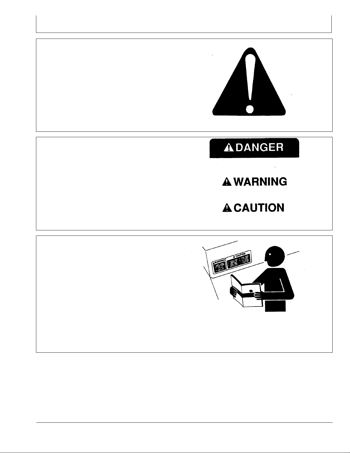
Understand Signal Words
A signal word—DANGER, WARNING, or CAUTION—is
used with the safetyalert symbol. DANGER identifies the
most serious hazards.
DANGER or WARNING safety signs are located near
specific hazards. General precautions are listed on
CAUTION safety signs. CAUTION also calls attention to
safety messages in this manual.
T81389 —UN—07DEC88
DX,ALERT 1929SEP981/1
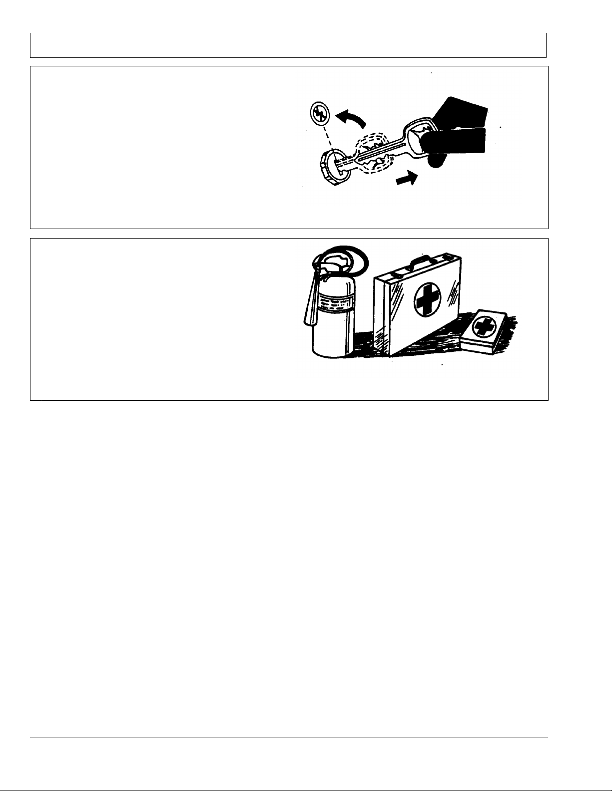
Follow Safety Instructions
Carefully read all safety messages in this manual and on
your machine safety signs. Keep safety signs in good
condition. Replace missing or damaged safety signs. Be
sure new equipment components and repair parts include
the current safety signs. Replacement safety signs are
available from your John Deere dealer.
There can be additional safety information contained on
parts and components sourced from suppliers that is not
reproduced in this operator’s manual.
Learn how to operate the machine and how to use controls
properly. Do not let anyone operate without instruction.
Keep your machine in proper working condition.
Unauthorized modifications to the machine may impair the
function and/or safety and affect machine life.
TS187 —19—30SEP88
DX,SIGNAL 1903MAR931/1
TS201 —UN—23AUG88
If you do not understand any part of this manual and need
assistance, contact your John Deere dealer.
DX,READ 1916JUN091/1
051
102110
PN=5
Page 6
Safety
Park Machine Safely
Before working on the machine:
Lower all equipment to the ground.
•
Stop the engine and remove the key.
•
Disconnect the battery ground strap.
•
Hang a "DO NOT OPERATE" tag in operator station.
•
Prepare for Emergencies
Be prepared if a fire starts.
Keep a first aid kit and fire extinguisher handy.
Keep emergency numbers for doctors, ambulance
service, hospital, and fire department near your telephone.
TS230 —UN—24MAY89
DX,PARK 1904JUN901/1
TS291 —UN—23AUG88
DX,FIRE2 1903MAR931/1
052
102110
PN=6
Page 7
Practice Safe Maintenance
Understand service procedure before doing work. Keep
area clean and dry.
Never lubricate, service, or adjust machine while it is
moving. Keep hands, feet , and clothing from powerdriven
parts. Disengage all power and operate controls to relieve
pressure. Lower equipment to the ground. Stop the
engine. Remove the key. Allow machine to cool.
Securely support any machine elements that must be
raised for service work.
Keep all parts in good condition and properly installed.
Fix damage immediately. Replace worn or broken parts.
Remove any buildup of grease, oil, or debris.
On selfpropelled equipment, disconnect battery ground
cable () before making adjustments on electrical systems
or welding on machine.
On towed implements, disconnect wiring harnesses from
tractor before servicing electrical system components or
welding on machine.
Safety
Support Machine Properly
Always lower the attachment or implement to the ground
before you work on the machine. If the work requires
that the machine or attachment be lifted, provide secure
support for them. If left in a raised position, hydraulically
supported devices can settle or leak down.
Do not support the machine on cinder blocks, hollow tiles,
or props that may crumble under continuous load. Do not
work under a machine that is supported solely by a jack.
Follow recommended procedures in this manual.
When implements or attachments are used with a
machine, always follow safety precautions listed in the
implement or attachment operator’s manual.
TS218 —UN—23AUG88
DX,SERV 1917FEB991/1
TS229 —UN—23AUG88
DX,LOWER 1924FEB001/1
053
102110
PN=7
Page 8
Safety
Keep Riders Off Machine
Only allow the operator on the machine. Keep riders off.
Riders on machine are subject to injury such as being
struck by foreign objects and being thrown off of the
machine. Riders also obstruct the operator’s view
resulting in the machine being operated in an unsafe
manner.
Handle Electronic Components and Brackets Safely
Falling while installing or removing electronic components
mounted on equipment can cause serious injury. Use a
ladder or platform to easily reach each mounting location.
Use sturdy and secure footholds and handholds. Do not
install or remove components in wet or icy conditions.
TS290 —UN—23AUG88
DX,RIDER 1903MAR931/1
If installing or servicing a RTK base station on a tower or
other tall structure, use a certified climber.
If installing or servicing a global positioning receiver mast
used on an implement, use proper lifting techniques and
wear proper protective equipment. The mast is heavy and
can be awkward to handle. Two people are required when
mounting locations are not accessible from the ground
or from a service platform.
Operate Guidance Systems Safely
Do not use AutoTrac system on roadways.
Always turn off (Deactivate and Disable) AutoTrac
•
system before entering a roadway.
Do not attempt to turn on (Activate) AutoTrac system
•
while transporting on a roadway.
AutoTrac and iGuide are intended to aid operator in
performing field operations more efficiently. Operator is
always responsible for machine path. To prevent injury
to operator and bystanders:
DX,WW,RECEIVER 1924AUG101/1
Verify the machine, implement, and iGuide are set up
•
correctly.
Remain alert and pay attention to surrounding
•
environment.
Take control of steering wheel when necessary to
•
avoid field hazards, bystanders, equipment, or other
obstacles.
Stop operation if poor visibility conditions impair your
•
ability to operate the machine or identify people or
obstacles in machine path.
JS56696,00003A0 1922JUL081/1
TS249 —UN—23AUG88
054
102110
PN=8
Page 9

Getting Started
Theory of Operation
iGuide is a passive implement guidance system which
allows a machine to be driven in such a way as to keep
the implement on its desired track. It is able to do this
with a StarFire™ GPS receiver on both the machine and
the implement.
The following criteria are required:
Machine receiver (iTC only or SF3000)
•
Implement receiver (iTC only or SF3000)
•
iGuide requires a second receiver installed on the
implement and connected to the machine’s Implement
CAN Bus through the ISO connector. The following items
need to be included:
Hardware Needed:
Constant power harness on machine
•
Front Extension harness
•
Center Extension harness (as needed for long
•
implements)
Rear Extension harness (as needed for tow behind air
•
cart)
StarFire is a trademark of Deere & Company
GreenStar is a trademark of Deere & Company
AutoTrac is a trademark of Deere & Company
Implement Harness(s) for receiver (quantity may vary)
•
Implement GPS Bracket and receiver
•
Compatible only with GreenStar™ 2 2600 display (GS2)
•
and GreenStar™ 3 2630 (GS3)
Software and Settings:
Update StarFire receiver software.
•
NOTE: When updating the receiver software, only
one receiver may be connected to the CAN
Bus while updating the software. Software
updates for both receivers must be performed
at the vehicle receiver location.
Updated GreenStar display software
•
Machine and implement setup
•
Machine receiver TCM calibration
•
Implement receiver setup including offsets and TCM
•
calibration
Other setup including AutoTrac™, Client, Farm, Field
•
and so on
CZ76372,00001CA 1912OCT101/1
101
102110
PN=9
Page 10

Getting Started
Making Implement Guidance Function
Implement Guidance will work with pull type implements
only.
The following criteria are required:
In iGuide mode, both receivers must have the same
•
receiver level (RTK)
iGuide software installed on the GreenStar display
•
iGuide activation for the GreenStar display
•
AutoTrac SF2™ activation on display
•
AutoTrac and iGuide setup complete (incomplete setup
•
would prevent operator from activating guidance)
Updated StarFire iTC™ software on the implement
•
Implement Guidance is designed to give implement
control for the first implement.
iGuide does not support:
AutoTrac SF1™ Signal Level
•
AutoTrac SF2™ Signal Level
•
Tow Between Air Carts
•
Integral Implements (3pt)
•
Balers
•
Mowers and MowerConditioners that can swing left and
•
right behind the machine (unless using a fixed offset)
Wideswinging drawbar on 9X00T tractors
•
AutoTrac Universal Steering Kit™ (Original or 200)
•
Bedded Crops
•
Standing row crop applications
•
Bedded crop applications (see iSteer if this is needed)
•
Circle Track
•
Original GSD4 Displays
•
GreenStar 2 1800 Display
•
Original StarFire Receivers
•
NH3 Cart behind Air Cart
•
NOTE: Make sure AutoTrac is properly setup and
adjustments are completed prior to using iGuide.
NOTE: iGuide performance is contingent upon the ability
of the machine to compensate for the implement. If
the machine is not weighted properly or slippage is
excessive, iGuide performance may be degraded.
NOTE: It is recommended to always save a backup copy
of AB lines from the data card to your computer.
This best practice will ensure data will be safe in
case of Data Card or Compact Flash Card problems.
NOTE: Always verify implement dimensions are correct
when using the “out of box” dimensions from
the GreenStar display or Apex.
NOTE: iGuide does not support the use of the 7.6
cm (3 in.) extension with the 22.9 cm (9 in.)
antennas on the implement AutoTrac RTK™ radio.
iGuide will support only the 30.5 cm (12 in.) RTK
antenna or the high gain antennas to be used
on the RTK radio at the implement.
NOTE: iGuide will not support reverse mode, this
functionality is exclusive to AutoTrac.
NOTE: iGuide performance is degraded when the
machine is in a "crabbing" condition with the front
wheels parallel or near parallel to the guidance path
and the rear wheels at an angle to the line.
NOTE: Do not mount the implement receiver higher than
4.0 m (13.1 ft.) for transportation purposes.
AutoTrac SF2 is a trademark of Deere & Company
StarFire iTC is a trademark of Deere & Company
AutoTrac SF1 is a trademark of Deere & Company
AutoTrac Universal Steering Kit is a trademark of Deere & Company
AutoTrac RTK is a trademark of Deere & Company
Accuracy
A GreenStar AutoTrac RTK Assisted Steering System
with iGuide may provide up to a 60% improvement in
implement accuracy versus a GreenStar AutoTrac RTK
Assisted Steering System without iGuide.
Accuracy is measured at the implement and may be
•
affected by various factors, including ground conditions,
implement performance, tractor performance,
ballasting, and speed. The performance of the AutoTrac
CZ76372,00001C9 1906OCT101/1
RTK system with iGuide is contingent upon the tractor’s
ability to effectively locate the implement. Therefore, if
the tractor is not weighted properly or wheel slippage
is excessive, the system’s performance and accuracy
may be degraded.
Stated implement accuracy improvement is the
•
improvement in the total percentage of seed placed
within +/ 5 cm (2 in.) of its desired location, as
measured in field tests.
JS56696,000052E 1901APR091/1
102
102110
PN=10
Page 11
Getting Started
iGuide Activation
See GreenStar Display Operator Manual for activating.
To activate iGuide, please visit www.StellarSupport.com
or call our Customer Contact Center with the following
items in hand:
Useful Buttons and Icons
The MENU Softkey allows access to all display
applications. The MENU Softkey will be on every display
screen.
The HOME Softkey allows accessing the currently defined
home page.
Press the GREENSTAR Softkey to access GreenStar
applications.
iGuide Order Number
•
GreenStar display Serial Number
•
GreenStar display Challenge Code
•
PC8663 —UN—05AUG05
MENU Softkey
PC9033 —UN—17APR06
HOME Softkey
PC12685 —UN—14JUL10
CZ76372,00001CB 1912OCT101/1
CZ76372,00001CC 1912OCT101/11
CZ76372,00001CC 1912OCT102/11
Use the STARFIRE MACHINE Softkey to setup the
vehicle StarFire Receiver and start the TCM calibration
for this receiver.
NOTE: The machine receiver must be a StarFire iTC.
GREENSTAR 3 Softkey
CZ76372,00001CC 1912OCT103/11
PC9965 —UN—09FEB07
STARFIRE MACHINE Softkey
Continued on next page CZ76372,00001CC 1912OCT104/11
103
102110
PN=11
Page 12
Getting Started
Use the STARFIRE IMPLEMENT Softkey to setup the
implement Receiver and start the TCM calibration for this
receiver. The Serial Number of the receiver is shown on
this button.
NOTE: The implement receiver must be a StarFire iTC.
Press the GUIDANCE Softkey to input required
information on desired Guidance Operation.
Press the EQUIPMENT Softkey to define Machine,
Implement and Implement receiver offsets.
PC9966 —UN—09FEB07
STARFIRE IMPLEMENT Softkey
CZ76372,00001CC 1912OCT105/11
PC12947 —UN—12OCT10
Guidance Softkey
CZ76372,00001CC 1912OCT106/11
PC12948 —UN—12OCT10
Use CANCEL button to ignore the changes made to this
page.
Use ENTER button to accept the current changes and
get back to the last page.
EQUIPMENT Softkey
CZ76372,00001CC 1912OCT107/11
PC8582 —UN—01NOV05
CANCEL Button
CZ76372,00001CC 1912OCT108/11
PC8649 —UN—01NOV05
ENTER Button
Continued on next page CZ76372,00001CC 1912OCT109/11
104
102110
PN=12
Page 13
Getting Started
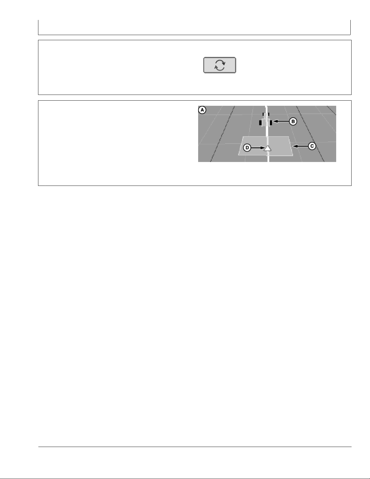
Use Offset Toggle button to toggle lateral offset from left
to right and vice versa.
Machine icon on guidance screen represents the location
of the machine.
Implement icon on guidance screen represents the
location of the implement.
Guidance reference point on guidance screen represents
the location of the guidance point for the system.
A—Guidance Screen
B—Machine Icon
C—Implement Icon
D—Guidance Reference Icon
PC10846 —UN—07DEC07
Offset Toggle Button
CZ76372,00001CC 1912OCT1010/11
PC11041 —UN—19FEB08
Guidance Screen Icons
CZ76372,00001CC 1912OCT1011/11
105
102110
PN=13
Page 14
Setup
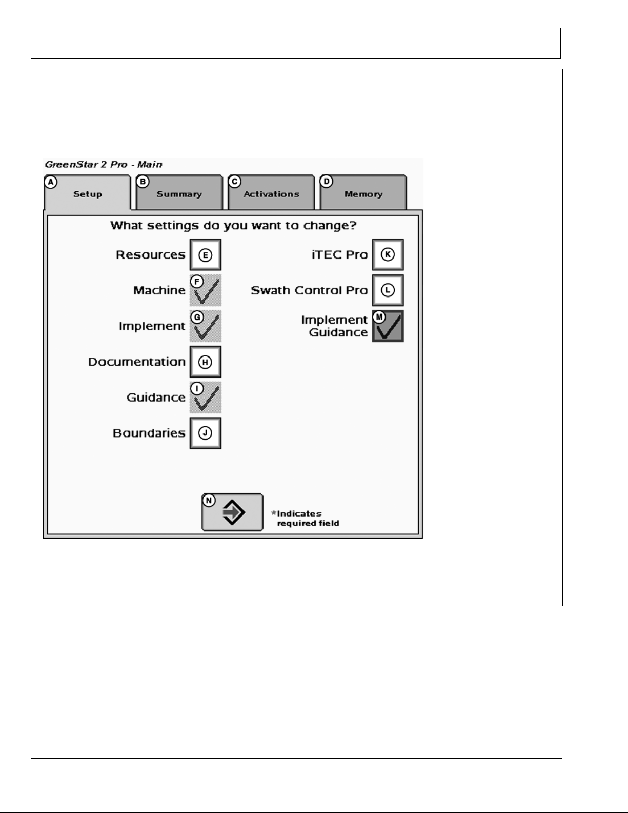
Getting Started
To make iGuide function, the following criteria are required
to be setup:
Machine setup and offsets
•
Implement setup and offsets
•
Machine GPS receiver settings under StarFire softkey
•
Implement GPS receiver settings under StarFire softkey
•
Guidance Setting—Tracking mode, Implement
•
Guidance Mode, and iGuide settings
These items can be set up separately or the Setup Wizard
can be used by checking the Implement Guidance option
(M). To access the Setup Wizard, select Softkey (F)
(GreenStar).
A—Setup Tab
B—Summary Tab
C—Activations Tab
D—Memory Tab
Setup Wizard
E—Resources Check Box
F— Machine Check Box
G—Implement Check Box
H—Documentation Check Box
151
I— Guidance Check Box
J— Boundaries Check Box
K—iTEC Pro Check Box
L— Swath Control Pro Check Box
PC11791 —UN—09MAR09
M—Implement Guidance Check
Box
N—Next Page
CZ76372,00001CD 1906OCT101/1
102110
PN=14
Page 15
Setup
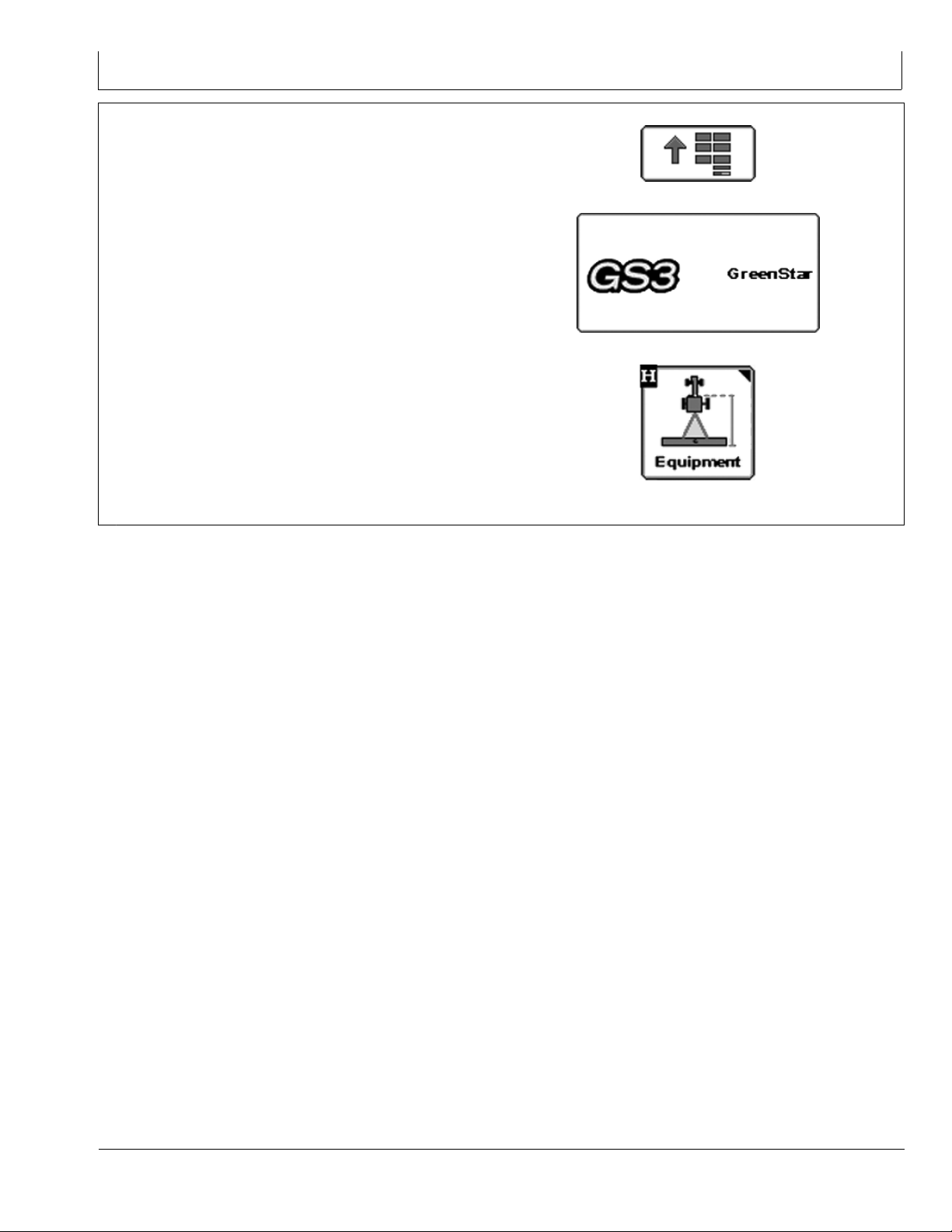
Machine Setup
MENU >> GREENSTAR >> EQUIPMENT allows access
to MACHINE and IMPLEMENT setup screens.
PC8663 —UN—05AUG05
PC12685 —UN—14JUL10
PC12948 —UN—12OCT10
Continued on next page CZ76372,00001CE 1912OCT101/2
MENU Softkey
GREENSTAR 3 Softkey
EQUIPMENT Softkey
152
102110
PN=15
Page 16
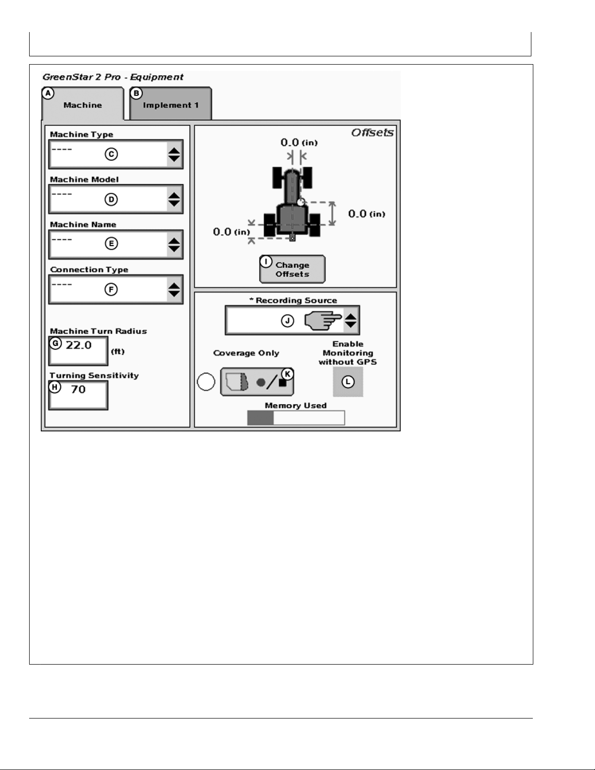
Setup
A—Machine Tab
B—Implement 1 Tab
C—Machine Type DropDown
Menu
D—Machine Model DropDown
Menu
E—Machine Name DropDown
Menu
F— Connection Point DropDown
Menu
NOTE: Machine name must be defined in order to
change offsets. All offsets will be saved under
the current machine name.
The Machine tab is required to be populated with the
following equipment information:
Machine Type—Vehicle type being used (Example:
•
Tractor).
Machine Name—Allows the operator to save
•
vehiclespecific offsets.
Connection Type—Defines how the implement is
•
attached to the machine.
Rear Rigid 3pt (not compatible with iGuide)
Rear Pivot 2pt
Machine Tab
G—Machine Turn Radius
InputBox
H—Turning Sensitivity InputBox
I— Change Offsets Button
J— Recording Source DropDown
Menu
K—Record/Pause Button
L— Enable Monitoring Without
GPS Check Box
Rear Pivot Drawbar
Rear Pivot Wagon Hitch (for European use)
Front Rigid 3pt (not compatible with iGuide)
Machine Offsets—modify by pressing Change Offsets
•
button (I).
Verify offsets correspond to the machine selected.
•
Machine Model—Model number of the vehicle being used.
For John Deere vehicles, model numbers will be available
from the dropdown list.
NOTE: Machine Model is not required for iGuide operation.
NOTE: Machine Turn Radius and Turning Sensitivity
are for use with iTEC Pro only.
CZ76372,00001CE 1912OCT102/2
PC10802 —UN—08JUL08
153
102110
PN=16
Page 17

Setup
Machine Offsets
Change Offsets
MENU >> GREENSTAR2 PRO Softkey >> EQUIPMENT
Softkey
Press CHANGE OFFSET button on Machine Setup
screen.
Enter machine offsets:
PC8663 —UN—05AUG05
PC12685 —UN—14JUL10
PC12948 —UN—12OCT10
PC11204 —UN—14JUL08
MENU Softkey
GREENSTAR 3 Softkey
EQUIPMENT Softkey
CHANGE OFFSETS Button
Continued on next page CZ76372,00001DC 1912OCT101/3
154
102110
PN=17
Page 18

InLine distance from nonsteering axle to GPS receiver
(B) will be
Row crop tractors—rear axle
•
Articulated tractors—front axle
•
Track tractors—rear axle
•
NOTE: Offset (B) for track tractors should be measured
from the receiver to the pivot point.
Offset Toggle button (E) toggles the receiver from the left
side of machine to the right side.
Verify that the correct connection point is selected and
measure from the center of nonsteering axle to the
center of connection point (Example: center of drawbar
pin or lower links, except in the case of a rear pivot 2pt
mount—measure to the pivot point of the implement
tongue).
NOTE: Offset (C) will change when the connection
point changes.
IMPORTANT: Offsets must be accurate because they
will be used to calculate the guidance
path for iGuide.
Setup
A—Lateral distance from
centerline of machine to
GPS receiver
B—Inline distance from
nonsteering axle to GPS
receiver
C—Inline distance from
nonsteering axle to
connection point
PC11898 —UN—01APR09
Machine Offsets
D—Vertical distance from the
GPS receiver to the ground
E—Offset Toggle Button
F— NonSteering Location
DropDown Menu
Machine Offsets—The machine and implement offsets
are important for implement guidance to function properly.
1. On Track machines, the nonsteering axle should be
selected as rear axle.
2. Offsets B and C should be measured to the turning
point or pivot point of the machine. For example: when
turning machine, it usually does not rotate on the rear
axle but somewhere in front of the rear axle.
This dimension can be measured by turning the machine
in a fairly tight turn, such as an end turn. Stop half way
through the turn. Looking at the inside track and its
relationship to the tracks on the ground, determine the
pivot point of the machine. Vehicle ballasting and drawbar
load could affect these offsets.
X—Pivot Point Y—Tractor Tracks
CZ76372,00001DC 1912OCT102/3
PC11205 —UN—14JUL08
Track Machines
CZ76372,00001DC 1912OCT103/3
155
102110
PN=18
Page 19

Setup
Implement Setup
NOTE: The implement setup should be verified
before operating iGuide.
MENU >> GREENSTAR >> EQUIPMENT >> Then press
Implement Tab
PC8663 —UN—05AUG05
PC12685 —UN—14JUL10
PC12948 —UN—12OCT10
Continued on next page CZ76372,00001CF 1912OCT101/2
MENU button
GREENSTAR 3 Softkey
EQUIPMENT Softkey
156
102110
PN=19
Page 20

Setup
Implement Tab
A—Machine Tab
B—Implement 1 Tab
C—Implement 2 Tab
D—Implement Type DropDown
Menu
E—Implement Model DropDown
Menu
F— Implement Name DropDown
Menu
Press Implement 1 tab to get to the implement setup page.
NOTE: All offsets including GPS offsets on the implement
will be stored to the implement name.
The name will also be the base for transferring
data to the desktop software.
G—Change Offsets Button
H—GPS Offsets Button
I— Change Widths Buttons
For the implement setup, the following information is
required to be populated:
Implement Type (D)
•
Implement Name (F)
•
CZ76372,00001CF 1912OCT102/2
PC11178 —UN—14JUL08
157
102110
PN=20
Page 21

Implement Offsets
Press CHANGE OFFSET button on Implement Setup
screen.
Implement name must be defined to save implement
offsets.
Implement Offsets—Used to define the actual implement
position relative to the machine.
Control Point—The location around which the implement
rotates.
Enter Implement Offsets:
A) Inline distance from connection point to front of
•
implement. On pulltype implements, think of this as the
tongue. This would be the distance from the connection
point to the first point of ground engagement (front
ranks of field cultivator, seed drop point on a planter).
For planters with a 2pt mount, measure from where the
planter pivots just behind the 2pt.
B) Inline distance from front to rear of implement. On
•
ground engaging tools, this is the distance from the front
rank of sweeps or points to the rear rank. On a standard
pull type sprayer, this offset would be 0 and the sprayer
has nozzles at the same point along the boom.
C) Lateral distance from connection point to control
•
point of implement. This is the lateral distance from the
center of the machine to the center of the implement,
which will be 0.0 for most common implements.
NOTE: Examples of equipment that will not be centered
include most split row planters with an even
number of 38 cm (15 in.) rows, (Examples: 1790
12/24, 16/32 CCS, 24R15 or 32R15) unless
using an adjustable hitch crossbar.
Setup
A—Inline distance from
connection point to front of
implement.
B—Inline distance from front
to rear of implement.
C—Lateral distance from
connection point to control
point of implement.
D—Inline distance from
connection point to control
point of implement.
PC11838 —UN—20MAR09
Offsets
E—Inline distance from
connection point to
connection point for
second implement. Value
only needed if second
implement is used.
F— Offset Toggle Button
G—A+B Documentation/Swath
Control location when in
use.
For the implements listed, it is required to enter an
implement offset dimension C on the implement
offset page. By entering implement offset
dimension C, iGuide will make the necessary
adjustments for the system to perform accurately.
Another example of this scenario is a planter
with a 2pt hitch offset of 19 cm (7.5 in.) to
the right. This planter must have an offset
of 19 cm (7.5 in.) entered for dimension C
on the implement offsets page.
NOTE: When using an adjustable hitch crossbar,
a lateral offset for the machine and
implement is needed.
D) Inline distance from connection point to control point
•
of implement. In many cases, this distance will be from
the connection point to the carrying wheels. For proper
turns, measure this distance with implement at the
height it typically will be at while in the lower position.
For planters with a 2pt mount, measure from where the
planter pivots just behind the 2pt.
E) Inline distance from connection point to connection
•
point for second implement. Value only needed if
second implement is used.
See MACHINE IMPLEMENT DIMENSIONS section.
Continued on next page JS56696,0000503 1902APR091/2
158
102110
PN=21
Page 22

Change Widths—Used to enter implement width and
track spacing for guidance. Change implement width and
track spacing when changing implements. Implement
width and track spacing are independent of each other.
NOTE: IMPLEMENT tab will show HEADER for
Combines, ROW UNITS for Cotton Pickers,
and BOOM for Sprayer.
NOTE: Implement width may come from certain
controllers such as SeedStar.
Defining Implement Width and Track Spacing.
Implement Width and Track Spacing can be defined
two ways: enter the working width of the implement, or
enter the number of rows and the row spacing. To toggle
between these two, press the cm (ft)/(rows) button (A).
Setup
Implement Width cm (ft)/(rows)—enter total implement
working width or the number of rows and row spacing
distance.
This value is used to calculate total area when
documenting the operation.
Track Spacing—Used in guidance for how far each pass
is from the last pass. It is entered the same way as
Implement Width. For “perfect” guess rows, this distance
will be the same as Implement Width. To ensure some
overlap for tillage or spraying, or to account for some
GPS drift, you may choose to make the Track Spacing
somewhat less than the Implement Width.
Physical Width—The actual width of the entire implement
when being used in the field when the implement is raised.
It is sometimes larger than Implement Width.
Change Widths
A—Toggle Button
B—Implement Width InputBox
C—Track Spacing InputBox
D—Physical Width InputBox
E—Row Width InputBox
F— Row Width InputBox
NOTE: Physical Width is not used for Implement Guidance.
There are certain value constraints to make Implement
Guidance work refer to APPENDIX Valid Configuration.
JS56696,0000503 1902APR092/2
PC11072 —UN—29FEB08
159
102110
PN=22
Page 23

Implement GPS Offsets
Press GPS OFFSET button on Implement Setup screen.
This button will only be active if an implement GPS
receiver is connected to the CAN Bus.
Enter Implement GPS Offsets:
IMPORTANT: Drive a vehicle forward and have
the vehicle & implement in a straight line
before measuring and calculating these
dimensions. This is very important for
accurate measurements.
IMPORTANT: Values must be accurate because
they will be used to calculate the track for
implement guidance and documentation.
NOTE: Minor adjustments to dimension B on the
Implement 1 GPS Offsets page can result in
measurable changes in offtrack error performance.
When modifying this value, minor increment
changes 1 cm (0.5 in.) is recommended.
Setup
PC11841 —UN—23MAR09
GPS Offsets
There are certain value constraints to make iGuide work
refer to APPENDIX—VALID CONFIGURATION.
Measuring in line dimension from receiver to receiver
Measure the distance between the vehicle receiver to
the implement receiver and then compare to the total
of dimensions "B" and "C" from Machine Offsets Page
(section 155), and dimension "A" from the Implement
GPS Offsets Page (section 15 10). The physical distance
between the receivers should match the distance found in
adding these three dimensions.
Example:
Distance between vehicle and implement receivers =
•
255 inches
A—Inline distance from
connection point to GPS
receiver.
B—Lateral distance from
implement center to GPS
receiver.
C—Vertical distance from GPS
receiver to ground with
implement engaged.
Dimensions "B" in Vehicle offset page = 55, "C" in
•
D—Lateral offset toggle button
E—Verify implement fore/aft
and offsets in the StarFire
setup pages.
CZ76372,00001D0 1906OCT101/1
Vehicle offset page = 65, and "A" in Implement receiver
offset page = 135 in. In total equaling, 255 inches.
NOTE: Measure from middle of vehicle receiver to
middle of implement receiver.
NOTE: For articulated tractors, the distance from
receiver to connection point is B subtracted from
C. (i.e. distance = "C" "B" + "A")
CZ76372,00001D1 1906OCT101/1
1510
102110
PN=23
Page 24

Receiver Installation
Setup
Possible Mounting Location
A—Connection Point B—Control Point
The mounting example diagram has a distance of 10 m
(32.8 ft) from the connection point (A) to the control point
(B).
The minimum distance needed between the connection
point and the GPS receiver of 2 m (6.6 ft) incorporated
1511
PC11843 —UN—23MAR09
with the maximum of 2 m (6.6 ft) to left or right from center
gives possible mounting location (dark shaded portion
in example diagram).
The ideal mounting location should be as close as
possible to the control point (B) on the implement.
JS56696,0000510 1911DEC081/1
102110
PN=24
Page 25

Setup
GPS Receiver Setup
MENU >> STARFIRE iTC Implement >> SETUP tab
allows access to StarFire iTC setup on the implement.
NOTE: The implement receiver will detect its position
automatically when it is attached to the implement
receiver application harness. If there is no
implement receiver shown on the CAN bus,
check implement harness connection.
NOTE: Original StarFire receivers cannot be used on
the implement or machine for iGuide.
NOTE: When updating the receiver software, only
one receiver may be connected to the CAN
bus while updating the software. Software
updates for both receivers must be performed
at the machine receiver location.
The number below the text on the StarFire iTC Softkey
shows the serial number of the receiver.
On the StarFire Main page the receiver definition (Machine
or Implement) is shown in the headline.
PC8663 —UN—05AUG05
PC9966 —UN—09FEB07
PC9965 —UN—09FEB07
MENU Softkey
StarFire iTC Implement Softkey
StarFire iTC Machine Softkey
JS56696,0000505 1901APR091/4
Machine iTC Receiver
PC12310 —UN—28SEP09
Implement iTC Receiver
Continued on next page JS56696,0000505 1901APR092/4
1512
PC11529 —UN—10DEC08
102110
PN=25
Page 26

Setup
StarFire iTC Implement—Main
A—Info Tab
B—Setup Tab
C—Activations Tab
D—Serial Port Tab
E—Correction Mode DropDown
Menu
F— Correction Default CheckBox
G—Mount Direction DropDown
Menu
H—Fore/Aft InputBox
Select Correction Mode to match the desired correction
mode. iGuide requires both receivers to have the same
RTK differential correction level (SF1 and SF2 are not
compatible with iGuide).
See APENDIX—VALID CONFIGURATION for more
information.
I— Height InputBox
J— Enable Optimize Shading
CheckBox
K—Enable QuickStart CheckBox
L— Hours On After Shutdown
DropDown Menu
M—TCM On/Off Toggle Button
N—TCM Calibrate Button
Select the correct mounting direction. The preferred
mounting direction for the implement is forward.
NOTE: Face receiver directly straight forward or backward.
Continued on next page JS56696,0000505 1901APR093/4
PC11844 —UN—23MAR09
1513
102110
PN=26
Page 27

Enter the correct receiver height above the ground. To
measure the receiver height, put the implement at its
working depth (if possible) and measure the height. If this
is not possible, lower the implement to the ground, and
subtract the desired working depth to get the value to
be entered.
Example: 2210 field cultivator—Lower the implement so
the sweeps are on the ground. Measure the height from
the ground to the top of the receiver. Subtract the working
depth from this number and enter as the receiver height.
If the height measured equals 180 cm (71 in.) and your
desired working depth is 10 cm (4 in.), enter 170 cm (67
in.) as the receiver Height.
NOTE: Enter 0 for the Fore/Aft offset for the
implement receiver.
Hours After Shutdown— The use of this feature is
recommended when two StarFire receivers are connected
on the CAN Bus to prevent excessive battery discharge.
Set hours after shutdown between 3 and 12 hours.
Setup
For optimized performance make the Hours On After
Shutdown the same value as on the machine receiver.
PC11208 —UN—14JUL08
Rear View Of Mast
JS56696,0000505 1901APR094/4
1514
102110
PN=27
Page 28

TCM Calibration
Setup
TCM Calibration
A—Implement with one main axle B—Implement with carrying
wheels at the front and rear
One of the most important steps in making iGuide function
at its peak performance is the TCM Calibration for both
the machine and implement. If the TCM calibration is
not performed correctly then a bias could occur in the
machine, implement or both. A bias is when the machine
AutoTracs down and back on the same path and the wheel
tracks do not line up. This can be caused by a poor TCM
calibration or the receiver is not centered on the machine.
A bias can be fixed by either recalibrating the TCM or
entering a machine or implement GPS lateral offset.
NOTE: When checking for bias, turn iGuide to “none”
and use AutoTrac to check the machine bias.
If you need to check implement bias, use
iGuide. Use Straight track only.
NOTE: When performing a TCM calibration on the
implement receiver, the wheels of the main
frame need to be in the same location after
turning implement around so that the righthand
1515
wheels are in the same place as where the
lefthand wheels were.
NOTE: A TCM calibration should be performed
each time the receiver is moved to a different
implement or vehicle.
Tips for a good TCM calibration:
Let the receiver warm up for 10—15 minutes, especially
•
if the air temperature is cold.
Calibrate on a flat surface.
•
Make sure the machine or implement are level with
•
respect to the ground by having proper tire inflation,
correct ballasting, and the same tire sizes.
Follow diagram example for proper rotation of
•
implement during the calibration process.
For more information refer to your StarFire iTC users
manual.
Continued on next page JS56696,0000506 1909DEC081/3
102110
PN=28
PC11066 —UN—29FEB08
Page 29

Adjusting Lateral Offsets
If TCM’s have been properly calibrated and machine or
implement still cannot track on same line going both
directions, a lateral offset should be entered.
NOTE: Remember, when checking bias on machine,
use AutoTrac. When checking bias on
implement, use iGuide.
1. The offset will be half the distance the two paths were
offset and in the same direction.
2. When entering lateral offset for implement, enter a
GPS offset on GPS offsets page.
3. Remember, when looking at tracks on the ground,
machine and implement must be symmetrical. Tires
must have same spacing from center of machine or
implement.
4. Another way of getting the correct lateral offset for the
implement is to measure guess rows. This method will
work with the implement in the ground and will also
achieve good guess rows.
Before measuring guess rows, make sure row units
are correctly spaced from center of implement.
Make three adjacent passes (preferably in straight
track mode with iGuide on). Make sure passes are
long enough so system has time to become stable.
Measure distance between guess rows in the middle
of pass.
Setup
A—Second Pass
PC11507 —UN—09DEC08
Lateral Offsets
B—First Pass
NOTE: Do not measure the ends of the passes.
NOTE: Wheels must be accurately spaced on vehicle
axles. This is critical for calibration accuracy .
5. Implement GPS Lateral Offset Example— Using
the Lateral Offsets 2 graphic and trying to get 762
mm (30 in.) guess rows. The guess row that is too
narrow (overlap), was measured at 64 cm (25 in.).
The wide side guess row was measured at 89 cm (35
in.). Therefore a 6.4 cm (2.5 in.) GPS offset to the left
(narrow side) should be entered in the GPS Offsets
page.
JS56696,0000506 1909DEC082/3
PC11067 —UN—29FEB08
Lateral Offsets 2
JS56696,0000506 1909DEC083/3
1516
102110
PN=29
Page 30

Setup
Guidance Setup
Guidance Setup
MENU >> GREENSTAR >> GUIDANCE softkey >>
GUIDANCE SETTINGS tab (A)
Select desired Tracking Mode first (refer to AutoTrac
Operators Manual). If Curve Track was selected, check
Curve Track settings.
Set Implement Guidance Mode (B) to iGuide.
Select iGuide Settings (C) to define Slope Compensation
and iGuide sensitivity.
For information on Turning View, Turn Predictor, Lead
Compensation, Arrow Segments, and Tracking Tones
refer to the AutoTrac Operators Manual.
A—Guidance Settings Tab
B—Implement Guidance Mode
C—iGuide Settings
PC8663 —UN—05AUG05
PC12685 —UN—14JUL10
PC12947 —UN—12OCT10
MENU button
GREENSTAR 3 Softkey
GUIDANCE Softkey
Guidance Settings
Continued on next page CZ76372,00001DD 1912OCT101/6
1517
PC11792 —UN—09MAR09
102110
PN=30
Page 31

Slope compensation aids in helping drive the machine up
a hill to account for implement drift. It looks at the machine
roll angle and slope compensation value to determine the
amount to move the machine up hill. On a 5 degree slope
with a value of 2.54 cm (1.0 in.)/degree this will move the
machine 12.7 cm (5 in.) up the hill to compensate for
the implement drifting down hill. If the implement drifts
more than that, increase the slope compensation value.
If the implement drifts less than that, decrease the slope
compensation value.
Recommendation for use:
Unless the field is completely flat, the slope
•
compensation value can aid in keeping the implement
on line.
02 degrees—Slope compensation may not be needed.
•
Recommended starting value 1.3 cm (0.5 in.)/degree.
25 degrees—Slope compensation provides a moderate
•
amount of machine correction and is recommended to
be turned on. Typical values of 1.3 to 3.8 cm (0.5 to
1.5 in.)/degree.
5 degrees and above—Slope compensation is
•
recommended to be on. Typical values can range from
2 to 7.6 cm (0.8 to 3.0 in.)/degree.
NOTE: Values above 7.6 cm (3 in.)/degree should be
used with caution. On a 10 degree slope with
a value of 7.6 cm (3 in.)/degree, the system will
try to move the machine 76 cm (30 in.) up hill
to compensate for implement drift.
Using the Calibration Feature:
Machine and Implement should be tracking on line with
•
iGuide activated. Do not perform the calibration during
line acquisition.
If the current slope compensation value is more than 1.3
•
cm (0.5 in.)/degree difference, it may be better to enter
the value manually with the increment and decrement
buttons. If a large change is made, it could cause some
system instability until the system has time to react to
the large changes.
Calibrations made at roll angles between 25 degrees
•
may not be ideal for larger roll angles and vice versa.
NOTE: You cannot navigate away from the iGuide
screen while calibrating slope compensation. Stop
calibration then navigate to other screens.
Adjusting the value manually:
When transiting to a hillside and implement error is
•
showing the implement needs to move down hill, slope
compensation needs to be reduced.
If the implement error is showing implement needs
•
to move up hill, slope compensation value should be
increased.
When slope compensation (A) is checked, slope
compensation will be turned on.
Calibrated slope compensation displays the last slope
compensation value created during calibration.
Setup
A—Slope Compensation
On/Off
B—Calibrated Slope
Compensation Button
C—Slope Calibration Help
Button
D—Decrease Slope
Compensation Value
E—Calibrated Slope
Compensation Value
F— Increase Slope
Compensation Value
G—Decrease iGuide Sensitivity
H—iGuide Sensitivity Input
I— Increase iGuide Sensitivity
J— Machine Roll Angle
K—iGuide Status Pie
Slope compensation (E) is an input field allowing for
manual adjustment of the slope compensation value and
shows current compensation value.
Adjusting Slope Compensation Value
Slope Compensation can be changed by three methods:
1. Calibrate slope compensation by pressing (B). Also
see GUIDANCE SETUP for detailed information.
2. Use decrement (D) and increment (F) buttons to
change slope compensation value (E).
3. Manually enter Slope Compensation value (E).
Adjustment for slope compensation using decrement (D)
and increment (F) buttons is 0.01 cm (0.01 in.)/degree.
NOTE: Average slope compensation range is 1.3 to 8.9
cm/degree (0.5 to 3.5 in./degree). If value is higher,
recalibrate. If value is still too large, turn off slope
calibration. This can typically be seen on flat ground.
NOTE: If upon calibration, slope compensation value
is above 4.00, calibrate again. Recalibration
is recommended to verify a consistent slope
compensation value. If a consistent value is not
achieved, review the slope compensation guidelines
in the GUIDANCE SETUP section.
Continued on next page CZ76372,00001DD 1912OCT102/6
PC11793 —UN—10MAR09
1518
102110
PN=31
Page 32

The slope compensation can be calibrated rather than
manually entered.
1. iGuide must be active to calibrate
2. Calibrate at operating speed and with implement at
operating depth
3. Do not calibrate when
Roll angle is less than 2 degrees
Direction of roll angle may change
On tight curves
A line acquisition is occurring
4. Slope compensation may not be required on slopes
less than 5 degrees
5. Stop calibration after calibrated slope compensation
value stabilizes
Setup
CZ76372,00001DD 1912OCT103/6
The slope compensation value has changed. Please
accept the new value or cancel the changes to keep the
previous value.
Selecting the “Accept” button may cause the vehicle to
move laterally.
Slope Range
Degree
0 2 ~ 0.5 ~ 1.3
2 5 0.5 1.5 1.3 3.8
5 >
Inches / Degree Centimeter / Degree
0.8 3.0 2 7.6
Typical Value
If the new calibrated value is significantly outside these
ranges, you may need to recalibrate.
A—Previous Calibrated Slope
Compensation
B—New Calibrated Slope
Compensation
PC11794 —UN—09MAR09
Slope Compensation
CZ76372,00001DD 1912OCT104/6
Slope Compensation
Continued on next page CZ76372,00001DD 1912OCT105/6
1519
PC11795 —UN—09MAR09
102110
PN=32
Page 33

A—Up Hill
B—Down Hill
C—25.4 cm (10 in.)
D—Tractor
Setup
10 Degree Slope Compensation
E—Implement
F— Desire Path
PC11062 —UN—29FEB08
G—Implement Drift Path
Calculating Slope Compensation Manually
If the center of the machine and center of the implement
positions are 25.4 cm (10 in.) apart on a slope with a
roll angle of 10 degrees, the slope compensation value
should be set to 2.54 cm (1 in.) per degree (25.4 cm (10
in.) of drift divided by 10 degrees of roll angle). If there is
a 25.4 cm (10 in.) difference on a slope with a 5 degree
roll angle, then the value would be 5.1 cm (2 in.)/degree.
Implement Error / Roll Angle = Slope Compensation
NOTE: Recommended adjustment in 0.2 cm (0.05 in.)/deg.
iGuide Sensitivity
iGuide Sensitivity affects how aggressively the system
responds to implement error. This function is similar to
AutoTrac steer sensitivity.
iGuide Sensitivity allows the system to respond to
•
implement errors. Higher sensitivity enables iGuide to
quickly react to implement error.
Too high of a value may cause the system to oscillate
•
around the intended path. Too low of a value may cause
the implement to react slow when trying to maintain the
implement on the guidance path.
A starting value of 15 is recommended. Adjust the
•
sensitivity in small increments until optimal tracking
performance is achieved.
NOTE: Machine steer sensitivity may need to be increased
or decreased to keep the machine on the guidance
path. iGuide is dependent on the machines ability to
track accurately on the intended guidance path.
CZ76372,00001DD 1912OCT106/6
1520
102110
PN=33
Page 34

Operation
Operation of iGuide
MEMU >> GREENSTAR >> GUIDANCE allows access to
Guidance Settings and Shift Track Settings.
PC8663 —UN—05AUG05
PC12685 —UN—14JUL10
PC12947 —UN—12OCT10
Continued on next page CZ76372,00001DE 1912OCT101/2
MENU Softkey
GREENSTAR 3 Softkey
GUIDANCE Softkey
201
102110
PN=34
Page 35

Operation
GreenStar—Guidance
A—View Tab
B—Guidance Setting Tab
C—Shift Track Settings Tab
D—iTEC Pro Tab
E—Path Accuracy Indicator
F— Shift Track Left Button
G—Shift Track Center Button
H—Shift Track Right Button
In order to operate iGuide, a valid setup must be available
(see APPENDIX—VALID CONFIGURATION). AutoTrac
can be engaged when the “steering wheel” icon is visible
in the AutoTrac enable button.
While in iGuide mode, machine and implement icons are
displayed in the perspective view. The implement will
have the guidance triangle. The error bar (D) at the top of
the page will display the error at the implement.
Blue line—recorded implement path
•
White line—implement tracking line
•
For all other settings refer to the GreenStar Display
operator’s manual.
If iGuide is not set up correctly, the AutoTrac steer on/off
button will be shown as a wrench. If the diagnostic wrench
I— Steer Sensitivity InputBox
J— Set Track 0 Button
K—iGuide Status Pie
L— Steer On/Off button
M—iTEC Pro Status Pie
N—iTEC Pro Enable Button
O—iTEC Pro Icon
P—Implement Receiver Location
Icon
is pressed, the AutoTrac diagnostic pages will appear to
indicate which items are not properly set up. Once iGuide
is properly configured, the steer on/off button will replace
the diagnostic wrench.
When the AutoTrac diagnostic wrench button is selected,
the AutoTrac diagnostic page will be displayed. If the
valid configuration is not valid, select implement guidance
from the dropdown menu on the diagnostic page to view
implement guidance diagnostics.
NOTE: For Line acquisition, the vehicle must be
within the 40% of the tracking width and
within 80 degrees of the line.
CZ76372,00001DE 1912OCT102/2
PC11899 —UN—01APR09
202
102110
PN=35
Page 36

Integrating iGuide and iTEC Pro
Hardware and Software Requirements
In order to run iTEC Pro and iGuide simultaneously, the
following hardware and software are required:
1. Both receivers must be iTC receivers
2. RTK GPS signal level on both receivers
3. Vehicle must have integrated AutoTrac components
4. GreenStar 2 2600 display must have AutoTrac SF2
activation
Hardware and Software Requirements
In order to run iTEC Pro and iGuide simultaneously, the
following hardware and software are required:
1. Both receivers must be iTC receivers
2. RTK GPS signal level on both receivers
3. Vehicle must have integrated AutoTrac components
4. GreenStar Display must have AutoTrac SF2 activation
Setup
1. Complete iTEC Pro and iGuide vehicle and implement
setup as described in their separate Operator’s
Manual.
5. GreenStar 2 2600 display must have iGuide and iTEC
Pro software activation
6. Drawn implements
NOTE: Please check the iGuide OM for a
complete list of supported and not supported
implements and applications.
JS56696,0000522 1923APR091/1
5. GreenStar Display must have iGuide and iTEC Pro
software activation
6. Drawn implements
NOTE: Please check the iGuide OM for a
complete list of supported and not supported
implements and applications.
CZ76372,00001DF 1912OCT101/1
2. Control point distance should be set for optimal iGuide
performance.
JS56696,0000523 1923MAR091/1
251
102110
PN=36
Page 37

Operation
Integrating iGuide and iTEC Pro
GreenStar—Guidance
A—View Tab
B—Guidance Setting Tab
C—Shift Track Settings Tab
D—iTEC Pro Tab
E—Path Accuracy Indicator
F— Shift Track Left Button
G—Shift Track Center Button
H—Shift Track Right Button
1. Tracking Mode—The operation of iGuide and iTEC
Pro will be available only on straight tracking mode.
2. End of Turn Performance
a. When both systems are activated, the operator will
see two paths on the screen.
b. The solid white line is the implement path and
current guidance path.
I— Steer Sensitivity InputBox
J— Set Track 0 Button
K—iGuide Status Pie
L— Steer On/Off button
M—iTEC Pro Status Pie
N—iTEC Pro Enable Button
O—iTEC Pro Icon
c. The dashed white line is the projected vehicle path
and is shown as a reference for the operator.
d. If iTEC Pro detects a collision with an impassable
boundary, both solid and dashed line paths will turn
red until the collision is passed.
CZ76372,00001E0 1912OCT101/1
PC11845 —UN—23MAR09
252
102110
PN=37
Page 38

Integrating iGuide and iTEC Pro
Using Implement Receiver for
Documentation and Coverage Map
When using iGuide guidance mode, the documentation
and coverage map will use the implement receiver
position as a reference point.
When iGuide is not in use and the implement receiver
is connected to the CAN bus, the system will use the
implement receiver position for documentation and
coverage map purposes.
NOTE: If you are not using iGuide guidance mode and do
not want to use the Implement Receiver position as
a reference point for documentation and coverage
map, unplug the implement receiver from the CAN
Bus. After unplugging the Implement Receiver from
the CAN Bus, the GreenStar Display will use the
Machine Receiver position as a reference point
for documentation and coverage map.
CZ76372,00001E1 1912OCT101/1
253
102110
PN=38
Page 39

Tuning Guide
Setting Up Vehicle Offsets
Vehicle Offsets
Offsets “A”, “B”, “C”, and “D” are critical for iGuide to
operate efficiently.
A—Lateral distance from
centerline of machine to
GPS receiver
B—Inline distance from
nonsteering axle to GPS
receiver
C—Inline distance from
nonsteering axle to
connection point
D—Vertical distance from the
GPS receiver to the ground
E—Offset Toggle Button
F— NonSteering Location
DropDown Menu
Offset “D” should match Receiver Height from Machine
Receiver softkey.
PC11898 —UN—01APR09
Machine Offsets
JS56696,00006D7 1931AUG091/2
PC9965 —UN—09FEB07
StarFire iTC Machine
JS56696,00006D7 1931AUG092/2
301
102110
PN=39
Page 40

Tuning Guide
Setting Up Implement Offsets
Implement Offsets
Offsets “A”, “B”, and “D” are critical for iGuide to operate
efficiently.
Offset “E” is not required for iGuide.
NOTE: Offset “C” is required when using a non
centered implement.
A—Inline distance from
connection point to front of
implement.
B—Inline distance from front
to rear of implement.
C—Lateral distance from
connection point to control
point of implement.
D—Inline distance from
connection point to control
point of implement.
E—Inline distance from
connection point to
connection point for
second implement. Value
only needed if second
implement is used.
F— Offset Toggle Button
G—A+B Documentation/Swath
Control location when in
use.
Setting Up Implement GPS Offsets
Implement GPS Offsets
Offsets “A”, “B”, and “C” are critical for iGuide to operate
efficiently.
A—Inline distance from
connection point to GPS
receiver.
B—Lateral distance from
implement center to GPS
receiver.
C—Vertical distance from GPS
receiver to ground with
implement engaged.
D—Lateral offset toggle button
E—Verify implement fore/aft
and offsets in the StarFire
setup pages.
PC11838 —UN—20MAR09
Offsets
JS56696,00006D8 1931AUG091/1
GPS Offsets
Continued on next page CZ76372,00001E2 1912OCT101/3
302
PC11841 —UN—23MAR09
102110
PN=40
Page 41

Tuning Guide
Offset “C” should match Receiver Height from Implement
Receiver softkey.
Check the GreenStar Display for correct inline
distance between vehicle receiver and implement
receiver.
Measuring in line dimension from receiver to receiver:
Measure the distance between the vehicle receiver to the
implement receiver and compare with the sum of offsets
“B” and “C” from Vehicle Offset page and dimension “A”
from the Implement Receiver Offset page. The distance
between and the distance found in adding these three
offsets, should match.
Example:
Distance between vehicle and implement receivers is
•
647.7 cm (255 in.).
Offsets:
•
Offset “A” is 342.9 cm (135 in.)
Offset “B” is 139.7 cm (55 in.)
Offset “C” is 165.1 cm (65 in.)
Total: 647.7 cm (255 in.)
PC9966 —UN—09FEB07
StarFire iTC Implement Softkey
CZ76372,00001E2 1912OCT102/3
PC12219 —UN—19AUG09
Receiver Offsets
NOTE: When measuring distance between vehicle and
implement receivers, measure from middle of
vehicle receiver to middle of implement receiver.
NOTE: For articulated tractors, distance from receiver
to connection point is “B” subtracted from “C”
(Example: distance = “C” – “B” + “A”).
CZ76372,00001E2 1912OCT103/3
303
102110
PN=41
Page 42

Tuning Guide
Tuning Slope Compensation
Slope Compensation works as a lookahead for the
vehicle. Slope Compensation helps aids in moving the
vehicle up the hill to keep the implement on the guidance
line.
Slope Range
Degree
0—2 1.3 0.5
2—5 1.3—3.8 0.5—1.5
Greater Than 5
0—2 degrees Slope Compensation may not be needed
•
2—5 degrees Use of Slope Compensation is
•
Cm/Degree Inches/Degree
2.0—8.9 0.8—3.5
recommended to provide moderate amount of machine
correction
Greater than 5 degrees Use of Slope Compensation is
•
recommended
NOTE: If slope compensation value is above 4.00
after calibration, calibrate again. Recalibration
is recommended to verify a consistent slope
compensation value. If a consistent value is not
achieved, review the slope compensation guidelines.
General Slope Compensation Guidelines:
1. iGuide must be active to calibrate
2. Calibrate at operating speed with implement at
operating depth
Typical Value
A—Slope Compensation
On/Off
B—Calibrated Slope
Compensation Button
C—Slope Calibration Help
Button
D—Decrease Slope
Compensation Value
E—Calibrated Slope
Compensation Value
F— Increase Slope
Compensation Value
G—iGuide Status Pie
3. Do not calibrate when:
Roll angle is less than 2 degrees
Direction of roll angle may change
On tight curves
A line acquisition is occurring
4. Slope compensation may not be required on slopes
less than 5 degrees
5. Stop calibration after calibrated slope compensation
value stabilizes
JS56696,00006D4 1926AUG091/1
PC12220 —UN—27AUG09
Tuning iGuide Sensitivity
Tuning iGuide Sensitivity properly will ensure the system
responds quickly to line and heading acquisition.
iGuide Sensitivity works in a similar way as the AutoTrac
Sensitivity and will be different according to the soil
conditions, machine, and implement models. iGuide
Sensitivity is lower when soil condition is harder and is
higher when soil condition is softer.
Adjust AutoTrac Steering sensitivity for the vehicle.
Verify Implement Guidance Mode is set to “None”
•
Refer to GreenStar Display Operator’s Manual for
•
process of tuning steering sensitivity
PC12221 —UN—27AUG09
A—Decrease iGuide Sensitivity
B—iGuide Sensitivity
InputBox
C—Increase iGuide Sensitivity
NOTE: For some platforms, such as four wheel drive
tractors, use a higher AutoTrac Sensitivity
for best performance.
CZ76372,00001D2 1912OCT101/1
304
102110
PN=42
Page 43

Troubleshooting
Troubleshooting Tips
1. Implement receiver not showing up in the GreenStar
Display
Check if Constant Power Extension harness
(PF90550 or PF90551) is installed.
Check for latest software (version 2.3.1385 or
higher) on Implement Receiver.
Check if receiver is receiving Switched, Unswitched,
CAN Low and CAN High power.
Check machine fuse panel for blown fuses
2. Implement GPS loses RTK signal more often than
machine receiver
Check antenna on GPS receiver for tight
connection.
Verify receiver has good line of sight to the base
station.
Set machine to Vehicle Repeater. Only one
Repeater or Vehicle Repeater can be used for
selected base station ID.
3. Implement Error is not reduced in a reasonable
amount of time
Incorrect machine or implement offsets.
iGuide sensitivity is set too low.
Incorrect Slope compensation value.
Engage iGuide closer to desired path.
Adjust control point.
4. Machine or implement is “S’ing” around the line
iGuide sensitivity is too high.
Steer sensitivity is too high.
5. Guess rows having a reoccurring skip/overlap pattern
Calibrate TCM on implement and machine
receivers.
Change Implement GPS offsets.
Implement row units not properly spaced.
6. Reduced Accuracy
If possible, mount the implement receiver as
close as possible to the control point. Mounting
receiver too close to rear of machine may result
in less accurate performance. Mounting receiver
too far from control point may also cause poor
performance.
Control Point— location around which the
implement rotates. This is typically the axle of the
implement.
7. Adjusting the Control Point offset (examples)
If the implement consistently tracks inside curve,
increase control point offset.
If the implement consistently tracks outside curve,
decrease control point offset.
8. Slow to line acquisition and Sing when reentering
passes at headlands
Resume switch should be activated when making
the turn.
NOTE: Do not wait until implement is aligned to
push the resume switch as this may cause
Sing at the beginning of passes.
9. After unloading data in Apex and saving setup back
to the data card, iGuide produces wide and narrow
guess rows
Make sure the offsets saved in Apex are the same
as when you measured the vehicle, implement, and
implement receiver offsets.
If the offsets are the same, create a new machine
name, machine model, implement name, and
implement model. Then enter the measured offsets.
Recalibrate both TCMs (vehicle and implement).
For best results, calibrate the TCM on a flat surface.
NOTE: If the problem still exists, format or use a
new data card. Then enter the correct offsets
for the vehicle offset page, implement offset
page, and implement receiver offset page.
NOTE: If keeping the measured offsets, create
a unique vehicle and implement name to
store them under. If unique vehicle and
implement names are not used, GSDNet
updates will overwrite offsets.
10. iGuide is oversteering on flat ground (less than 2
degrees)
Verify Slope Compensation is off.
Lower iGuide Sensitivity.
11. iGuide respond for lateral implement draft is too slow
Verify Slope Compensation is on.
Recalibrate Slope Compensation.
Increment Slope Compensation value using the
increment button until the proper value is found.
Raise iGuide Sensitivity.
12. iGuide calculates a high value after Slope
Compensation Calibration
Check if iGuide was active during the calibration.
Check if calibration was performed on ground with
less than 2 degree of roll angle.
13. iGuide does not work properly with row crop cultivation
iGuide is not designed to work on row crop
cultivation.
14. Poor performance on articulated tractors
Verify if front axle has been selected as Non Steer
Axle and remeasure vehicle offsets.
15. Points to Remember
In iGuide mode, remember error on the display is
error at the implement. Error for iGuide may be
higher on the display than machine error was when
the system was in normal AutoTrac mode.
iGuide may not perform as well in tight turns or end
turns as it does on more gradual curves; especially
on severe slopes when the implement is sliding
down hill.
iGuide is a reactive system and can only respond to
implement errors.
System performance can be affected by several
factors on the machine and implement. Examples:
ballasting, tire inflation, hitch play, amount of
weight on the implement (seed, fertilizer, chemical),
second implement (air cart, tank), ground engaging
equipment in proper working order, and offsets,
values, and sensitivities in the GreenStar Display.
Continued on next page CZ76372,00001E3 1912OCT101/2
351
102110
PN=43
Page 44

Troubleshooting
Always verify correct implement dimensions
when using the “out of box” dimensions from the
GreenStar Display or Apex.
Valid Configuration
iGuide requires certain settings to be available and certain
offsets need to be within a defined range. If one of these
constraints is not given, tracking cannot be activated.
For a new, unknown implement, all offset will be zero as
a default.
General constraints:
Will not work with 3pt implements.
•
Implement receiver installed and set up to be an
•
implement receiver.
Both receivers need to have the same differential
•
correction level (RTK).
The following settings and constraints are mandatory for
the machine:
Machine type and name selected.
•
Rear pivot connection type selected.
•
Distance between connection point and non steering
•
axle is larger than 30 cm (11.8 in.).
The following settings and constraints are mandatory for
the implement:
CZ76372,00001E3 1912OCT102/2
PC11846 —UN—24MAR09
Implement Guidance diagnostics page 1
Implement type, name, and model are selected.
•
Distance between connection point and control point
•
shall be larger than 49 cm (1.6 ft).
Location of implement receiver is defined.
•
The distance between the connection point and the
•
implement GPS receiver needs to be larger than 201
cm (79 in.).
Lateral offset from control point to implement GPS
•
receiver shall be less than 201 cm (79 in.).
The following settings and constraints are mandatory for
the implement GPS receiver:
Implement receiver height should be between 50 cm
•
(20 in.) and 508 cm (200 in.).
A—View DropDown Menu
B—Information Column
C—Current Column
D—Status Column
E—Previous Page
F— Next Page
G—Valid Range Column
PC11797 —UN—09MAR09
Implement Guidance diagnostics page 2
JS56696,000050A 1910DEC081/1
352
102110
PN=44
Page 45

Specifications
4.84.8 8.8 9.8 10.9
12.9
12.9
12.9
12.9
10.9
9.8
8.8
4.8
Metric Bolt and Screw Torque Values
TS1670 —UN—01MAY03
Bolt or Class 4.8 Class 8.8 or 9.8 Class 10.9 Class 12.9
Screw
Lubricated
a
Dry
b
Lubricated
a
Dry
b
Lubricated
a
Dry
b
Lubricated
a
Size N∙m lbin N∙m lbin N∙m lbin N∙m lbin N∙m lbin N∙m lbin N∙m lbin N∙m lbin
M6 4.7 42 6 53 8.9 79 11.3 100 13 115 16.5 146 15.5 137 19.5 172
N∙m lbft N∙m lbft N∙m lbft N∙m lbft
M8 11.5 102 14.5 128 22 194 27.5 243 32 23.5 40 29.5 37 27.5 47 35
N∙m lbft N∙m lbft N∙m lbft
M10 23 204 29 21 43 32
N∙m
lbft
M12 40 29.5 50 37
75 55
55
40 63 46 80 59
95 70 110 80 140 105 130 95 165 120
75 55
M14 63 46 80 59 120 88 150 110 175 130 220 165 205 150 260 190
M16 100 74 125 92 190 140 240 175 275 200 350 255 320 235 400 300
M18 135 100 170 125 265 195 330 245 375 275 475 350 440 325 560 410
M20 190 140 245 180 375 275 475 350 530 390 675 500 625 460 790 580
M22 265 195 330 245 510 375 650 480 725 535 920 680 850 625 1080 800
M24 330 245 425 315 650 480 820 600 920 680 1150 850 1080 800 1350 1000
M27 490 360 625 460 950 700 1200 885 1350 1000 1700 1250 1580 1160 2000 1475
M30 660 490 850 625 1290 950 1630 1200 1850 1350 2300 1700 2140 1580 2700 2000
M33 900 665 1150 850 1750 1300 2200 1625 2500 1850 3150 2325 2900 2150 3700 2730
M36 1150 850 1450 1075 2250 1650 2850 2100 3200 2350 4050 3000 3750 2770 4750 3500
Torque values listed are for general use only, based on the strength of
the bolt or screw. DO NOT use these values if a different torque value or
tightening procedure is given for a specific application. For stainless steel
fasteners or for nuts on Ubolts, see the tightening instructions for the
specific application. Tighten plastic insert or crimped steel type lock nuts
by turning the nut to the dry torque shown in the chart, unless different
instructions are given for the specific application.
Shear bolts are designed to fail under predetermined loads. Always
replace shear bolts with identical property class. Replace fasteners with
the same or higher property class. If higher property class fasteners are
used, tighten these to the strength of the original. Make sure fastener
threads are clean and that you properly start thread engagement. When
possible, lubricate plain or zinc plated fasteners other than lock nuts,
wheel bolts or wheel nuts, unless different instructions are given for the
specific application.
a
“Lubricated” means coated with a lubricant such as engine oil, fasteners with phosphate and oil coatings, or M20
and larger fasteners with JDM F13C zinc flake coating.
b
“Dry” means plain or zinc plated without any lubrication, or M6 to M18 fasteners with JDM F13B zinc flake coating.
JS56696,0000237 1922JUL081/1
b
Dry
95 70
401
102110
PN=45
Page 46

Specifications
Unified Inch Bolt and Screw Torque Values
TS1671 —UN—01MAY03
Bolt or SAE Grade 1 SAE Grade 2
Screw
Lubricated
b
Dry
c
Lubricated
b
a
Dry
c
SAE Grade 5, 5.1 or 5.2 SAE Grade 8 or 8.2
Lubricated
b
Dry
c
Lubricated
b
Size N∙m lbin N∙m lbin N∙m lbin N∙m lbin N∙m lbin N∙m lbin N∙m lbin N∙m lbin
3.7 33 4.7 42 6 53
1/4
7.5
66 9.5 84 12 106 13.5 120 17 150
N∙m lbft N∙m lbft
7.7
5/16
68 9.8 86 12 106 15.5 137 19.5 172 25 221 28 20.5 35 26
N∙m lbft N∙m lbft
13.5 120 17.5 155 22 194 27 240 35 26 44 32.5 49 36 63 46
3/8
N∙m lbft N∙m lbft N∙m lbft
7/16
22 194 28 20.5 35 26 44 32.5 56 41 70 52 80 59 100 74
N∙m lbft
34 25 42 31 53 39 67 49 85 63 110 80 120 88 155 115
1/2
9/16
48 35.5 60 45 76 56 95 70 125 92 155 115 175 130 220 165
67 49 85 63 105
5/8
120 88 150 110 190 140 240 175 300 220 380 280 425 315 540 400
3/4
190 140 240 175 190 140 240 175 490 360 615 455 690 510 870 640
7/8
77
135 100 170 125 215 160 240 175 305 225
1 285 210 360 265 285 210 360 265 730 540 920 680 1030 760 1300 960
11/8
11/4
13/8
11/2
Torque values listed are for general use only, based on the strength of the bolt
or screw. DO NOT use these values if a different torque value or tightening
procedure is given for a specific application. For plastic insert or crimped steel
type lock nuts, for stainless steel fasteners, or for nuts on Ubolts, see the
tightening instructions for the specific application. Shear bolts are designed to fail
under predetermined loads. Always replace shear bolts with identical grade.
400 300 510 375 400 300 510 375 910 670 1150 850 1450 1075 1850 1350
570 420 725 535 570 420 725 535 1280 945 1630 1200 2050 1500 2600 1920
750 550 950 700 750 550 950 700 1700 1250 2140 1580 2700 2000 3400 2500
990 730 1250 930 990 730 1250 930 2250 1650 2850 2100 3600 2650 4550 3350
Replace fasteners with the same or higher grade. If higher
grade fasteners are used, tighten these to the strength of the
original. Make sure fastener threads are clean and that you
properly start thread engagement. When possible, lubricate
plain or zinc plated fasteners other than lock nuts, wheel bolts
or wheel nuts, unless different instructions are given for the
specific application.
a
Grade 2 applies for hex cap screws (not hex bolts) up to 6. in (152 mm) long. Grade 1 applies for hex cap screws over 6
in. (152 mm) long, and for all other types of bolts and screws of any length.
b
“Lubricated” means coated with a lubricant such as engine oil, fasteners with phosphate and oil coatings, or 7/8
in. and larger fasteners with JDM F13C zinc flake coating.
c
“Dry” means plain or zinc plated without any lubrication, or 1/4 to 3/4 in. fasteners with JDM F13B zinc flake coating.
JS56696,0000238 1922JUL081/1
Dry
c
402
102110
PN=46
Page 47

Index
Page
A
APPENDIX
Valid Configuration.................................................. 352
C
Control Point............................................................... 158
G
Getting Started ........................................................... 151
iGuide Activation ..................................................... 103
Theory of Operation ................................................ 101
To make iGuide Function ........................................ 151
Useful Buttons and Icons........................................ 103
Guidance Setup........................................................ 1517
H
Hardware.................................................................... 101
I
iGuide ....................................................................... 1517
iGuide activation ......................................................... 103
Implement GPS Offsets............................................ 1510
Implement GPS Receiver Setup............................... 1512
Implement Offsets ...................................................... 158
Implement Setup ........................................................ 156
Control Point ........................................................... 158
Implement Offsets................................................... 158
Implement Tab ........................................................ 156
Implement Widths ................................................... 159
Physical Width ........................................................ 159
Track Spacing ......................................................... 159
Implement Tab ............................................................ 156
Implement Widths....................................................... 159
Page
S
Setup
Getting Started........................................................ 151
Sofware and Settings ................................................. 101
T
TCM Calibration........................................................ 1515
Theory of Operation.................................................... 101
Hardware ................................................................ 101
Sofware and Settings.............................................. 101
To make iGuide Function............................................ 151
To Make iGuide Pro function
iGuide Activation ..................................................... 103
Track Spacing............................................................. 159
U
Useful Buttons and Icons............................................ 103
V
Valid Configuration ..................................................... 352
M
Machine Name ........................................................... 153
Machine Offsets.......................................................... 154
Change Offsets ....................................................... 154
Machine Setup............................................................ 152
Machine Tab............................................................ 152
Machine Tab ............................................................... 152
Machine Name........................................................ 153
Making Implement Guidance Function....................... 102
O
Operation of iGuide .................................................... 201
P
Physical Width ............................................................ 159
Index1
102110
PN=1
Page 48

Index
Index2
102110
PN=2
Page 49

John Deere Service Keeps You On The Job
John Deere Parts
We help minimize downtime by putting genuine John
Deere parts in your hands in a hurry.
That’s why we maintain a large and varied inventory—to
stay a jump ahead of your needs.
The Right Tools
Precision tools and testing equipment enable our Service
Department to locate and correct troubles quickly . . . to
save you time and money.
TS100 —UN—23AUG88
JS56696,0000239 1908FEB081/1
WellTrained Technicians
School is never out for John Deere service technicians.
Training schools are held regularly to be sure our
personnel know your equipment and how to maintain it.
Result?
Experience you can count on!
Prompt Service
Our goal is to provide prompt, efficient care when you
want it and where you want it.
We can make repairs at your place or at ours, depending
on the circumstances: see us, depend on us.
JOHN DEERE SERVICE SUPERIORITY: We’ll be around
when you need us.
TS101 —UN—23AUG88
JS56696,000023A 1908FEB081/1
TS102 —UN—23AUG88
JS56696,000023B 1908FEB081/1
IBC1
TS103 —UN—23AUG88
JS56696,000023C 1908FEB081/1
102110
PN=49
Page 50

Page 51

Page 52

 Loading...