

Page 1
StarFire™ iTC and RTK
OPERATOR’S MANUAL
StarFire iTC™ and RTK
OMPC20964 Issue J7 (ENGLISH)
DCYOMPC20964
CALIFORNIA
Proposition 65 Warning
Diesel engine exhaust and some of its constituents are
known to the State of California to cause cancer, birth
defects, and other reproductive harm.
If this product contains a gasoline engine:
WARNING
The engine exhaust from this product contains chemicals
known to the State of California to cause cancer, birth
defects or other reproductive harm.
The State of California requires the above two warnings.
John Deere Ag Management Solutions
(This manual replaces OMPC20677)
European Version
Printed in Germany
Page 2

Contents
Page Page
Safety ................................05-1
SETUP-GPS-PAGE 1 .....................25-4
Overview: SF2/RTK Activations, SF2
StarFire iTC Receiver
StarFire iTC Receiver .....................10-1
Subscription ..........................25-5
QuickStart Setup ........................25-8
TCM
GS2 Display—StarFire iTC
STARFIRE ITC softkey....................15-1
INFO tab ..............................15-2
SETUP tab .............................15-4
Correction Mode .........................15-5
Correction Frequency .....................15-5
Mount Direction .........................15-5
Fore/Aft ...............................15-6
Height.................................15-7
QuickStart .............................15-7
Hours On After Shutdown..................15-8
TCM Calibration .........................15-8
ACTIVATIONS tab ......................15-12
SERIAL PORT tab ......................15-15
Setup ...............................25-9
On/Off...............................25-9
Mount Direction.......................25-10
Calibrate Level .......................25-11
Height ..............................25-16
Fore/Aft.............................25-17
Differential Correction Setup...............25-18
Serial RS232 Output ....................25-19
Hours On After Shutdown.................25-20
INFO - GPS - PAGE 1 ...................25-21
INFO - GPS - PAGE 2 ...................25-23
Data Log .............................25-24
INFO - GPS - PAGE 3 ...................25-28
Satellite Tracking .......................25-29
NMEA Strings..........................15-16
SATELLITE INFORMATION softkey .........15-19
Satellite Predictor .......................15-23
DIAGNOSTIC softkey ....................15-24
READINGS tab.........................15-25
DATA LOGS tab........................15-26
Radio Self Test.........................15-33
StarFire Signal Monitoring System ..........15-34
Original GreenStar Display—RTK
Operating Mode .........................30-1
Vehicle Repeater ........................30-3
Quick Survey Mode ......................30-4
Absolute Mode ..........................30-5
Shared Base Station RTK Security ...........30-8
Time Slot .............................30-12
Network ID ............................30-13
GS2 Display—RTK
RTK softkey ............................20-1
Vehicle ................................20-3
Vehicle Repeater ........................20-5
Quick Survey Mode ......................20-6
Repeater .............................30-14
Operating Vehicle .......................30-15
RTK
Info Pages ..........................30-17
Info Pages ..........................30-18
Absolute Base Mode .....................20-6
RTK Network Configuration ................20-9
Shared Base Station RTK Security ..........20-11
Shared Base Station Security—Setup .......20-12
RTK Vehicle Security Status...............20-16
RTK Base Station Setup
Country Use Restrictions ..................35-1
System Overview ........................35-2
Installation of the RTK radio and antenna......35-4
Attaching RTK Harness ...................35-5
Original GreenStar Display—StarFire iTC
RTK Network Base Station Setup ...........35-6
Auto-Update ............................25-1 Multipathing ...........................35-10
Manual Software Update ..................25-2
StarFire Receiver ........................25-3
Continued on next page
All information, illustrations and specifications in this manual are based on
the latest information available at the time of publication. The right is
reserved to make changes at any time without notice.
COPYRIGHT2007
DEERE & COMPANY
Moline, Illinois
All rights reserved
A John Deere ILLUSTRUCTIONManual
i
121907
PN=1
Page 3

Page
RTK using Straight, Curves or Circle ........35-16
Example A ............................35-17
Operating Parameters ...................35-18
PDOP Definition ........................35-19
PDOP Operating Values..................35-21
StarFire Signal Monitoring System ..........35-23
Antenna Height.........................35-25
Specific Tower Setup Information ...........35-26
Utilizing Both The 91 m (300 ft) RTK
Extension Harness And Low Loss Coax
Cable ..............................35-27
Utilizing The RTK Extension Harness ........35-28
Utilizing A Repeater .....................35-28
Utilizing Just Low Loss Coax Cable .........35-29
Leaving The Radio And Receiver As A
Single Unit ..........................35-29
Troubleshooting and Diagnostics
Accessing GREENSTAR 2 Diagnostic
Addresses............................40-1
Accessing Original GREENSTAR Display
Fault Codes ..........................40-3
STARFIRE iTC Diagnostic Addresses ........40-4
Fault Codes—StarFire iTC .................40-8
Diagnostic Trouble Codes—StarFire iTC .....40-11
GreenStar Deluxe - Diagnostic Readings .....40-13
Contents
Specifications
Unified Inch Bolt and Screw Torque Values ....45-1
Metric Bolt and Screw Torque Values.........45-2
Declaration of Conformity ..................45-3
Safety Note Regarding the Subsequent
Installation of Electrical and Electronic
Appliances and/or Components ...........45-3
ii
121907
PN=2
Page 4
Safety
Recognize Safety Information
This is a safety-alert symbol. When you see this symbol
on your machine or in this manual, be alert to the
potential for personal injury.
Follow recommended precautions and safe operating
practices.
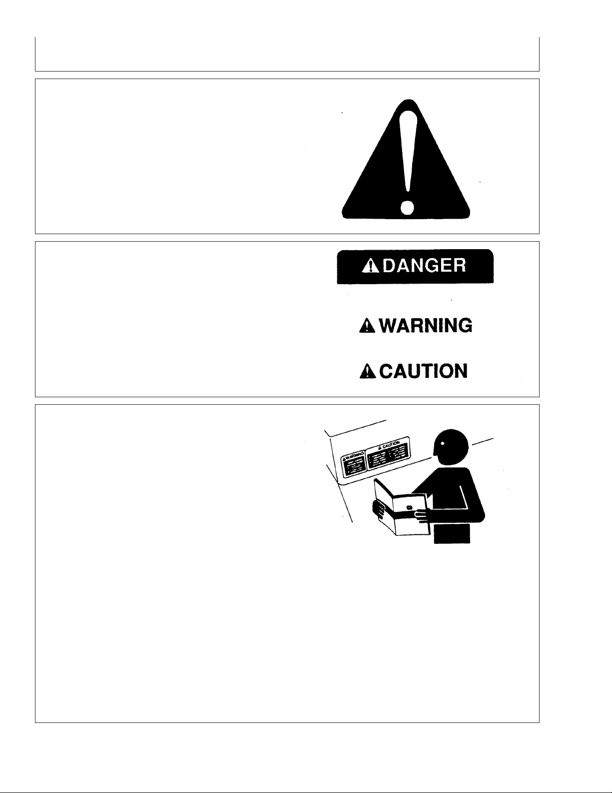
Understand Signal Words
A signal word—DANGER, WARNING, or CAUTION—is
used with the safety-alert symbol. DANGER identifies the
most serious hazards.
DANGER or WARNING safety signs are located near
specific hazards. General precautions are listed on
CAUTION safety signs. CAUTION also calls attention to
safety messages in this manual.
Follow Safety Instructions
Carefully read all safety messages in this manual and on
your machine safety signs. Keep safety signs in good
condition. Replace missing or damaged safety signs. Be
sure new equipment components and repair parts include
the current safety signs. Replacement safety signs are
available from your John Deere dealer.
DX,ALERT –19–29SEP98–1/1
T81389 –UN–07DEC88
TS187 –19–30SEP88
DX,SIGNAL –19–03MAR93–1/1
Learn how to operate the machine and how to use
controls properly. Do not let anyone operate without
instruction.
Keep your machine in proper working condition.
Unauthorized modifications to the machine may impair the
function and/or safety and affect machine life.
If you do not understand any part of this manual and need
assistance, contact your John Deere dealer.
05-1
TS201 –UN–23AUG88
DX,READ –19–03MAR93–1/1
121907
PN=4
Page 5
Safety
Prepare for Emergencies
Be prepared if a fire starts.
Keep a first aid kit and fire extinguisher handy.
Keep emergency numbers for doctors, ambulance service,
hospital, and fire department near your telephone.
Practice Safe Maintenance
Understand service procedure before doing work. Keep
area clean and dry.
Never lubricate, service, or adjust machine while it is
moving. Keep hands, feet , and clothing from
power-driven parts. Disengage all power and operate
controls to relieve pressure. Lower equipment to the
ground. Stop the engine. Remove the key. Allow machine
to cool.
Securely support any machine elements that must be
raised for service work.
Keep all parts in good condition and properly installed. Fix
damage immediately. Replace worn or broken parts.
Remove any buildup of grease, oil, or debris.
On self-propelled equipment, disconnect battery ground
cable (-) before making adjustments on electrical systems
or welding on machine.
DX,FIRE2 –19–03MAR93–1/1
TS291 –UN–23AUG88
On towed implements, disconnect wiring harnesses from
tractor before servicing electrical system components or
welding on machine.
05-2
TS218 –UN–23AUG88
DX,SERV –19–17FEB99–1/1
121907
PN=5
Page 6
Safety
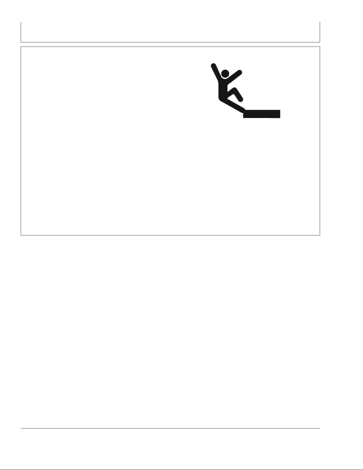
Install and Remove StarFire Receiver and Brackets Safely
When installing and removing the StarFire receiver, follow
these guidelines to prevent potential injury from falling:
• Use an appropriate ladder or platform to easily access
mounting location.
• Ensure sturdy and secure footholds and handholds.
• Avoid installing or removing receiver in wet or icy
conditions.
The receiver mast used on implements is heavy and can
be awkward to handle. If installing or removing a receiver
mast on an implement, follow these guidelines:
• Use two people for mounting locations not accessible
from the ground or a service platform.
• Use proper lifting techniques.
• Wear proper protective equipment.
PC10340 –UN–27SEP07
OUO6050,0000E4D –19–27SEP07–1/1
05-3
121907
PN=6
Page 7
StarFire iTC Receiver
StarFire iTC Receiver
Receiver is located on cab of machine. It receives global
positioning and differential correction signal through a
single receiver and integrates signal for use with system.
Terrain Compensation Module (TCM) is integrated into
receiver and is a navigational aid used with receiver to
enhance vehicle position and course parameters that GPS
provides. TCM corrects for vehicle dynamics such as roll
on side-slopes, rough terrain or varying soil conditions.
StarFire iTC Mounting Instructions
OUO6050,0000C0C –19–18OCT07–1/4
1. Read “Install and Remove StarFire Receiver and
Brackets Safely” in the Safety section.
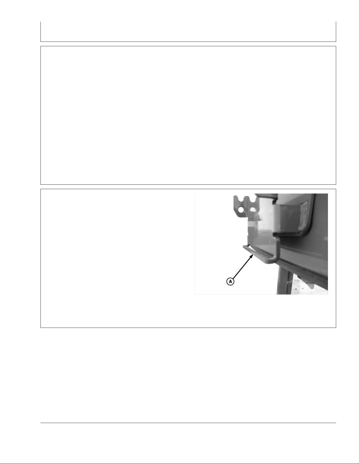
2. Verify that vehicle side receiver bracket bar (A) is not
bent inward or outward.
A—Bracket Bar
Continued on next page
PC8328 –UN–02SEP04
OUO6050,0000C0C –19–18OCT07–2/4
10-1
121907
PN=7
Page 8
StarFire iTC Receiver
PC8327 –UN–31AUG04
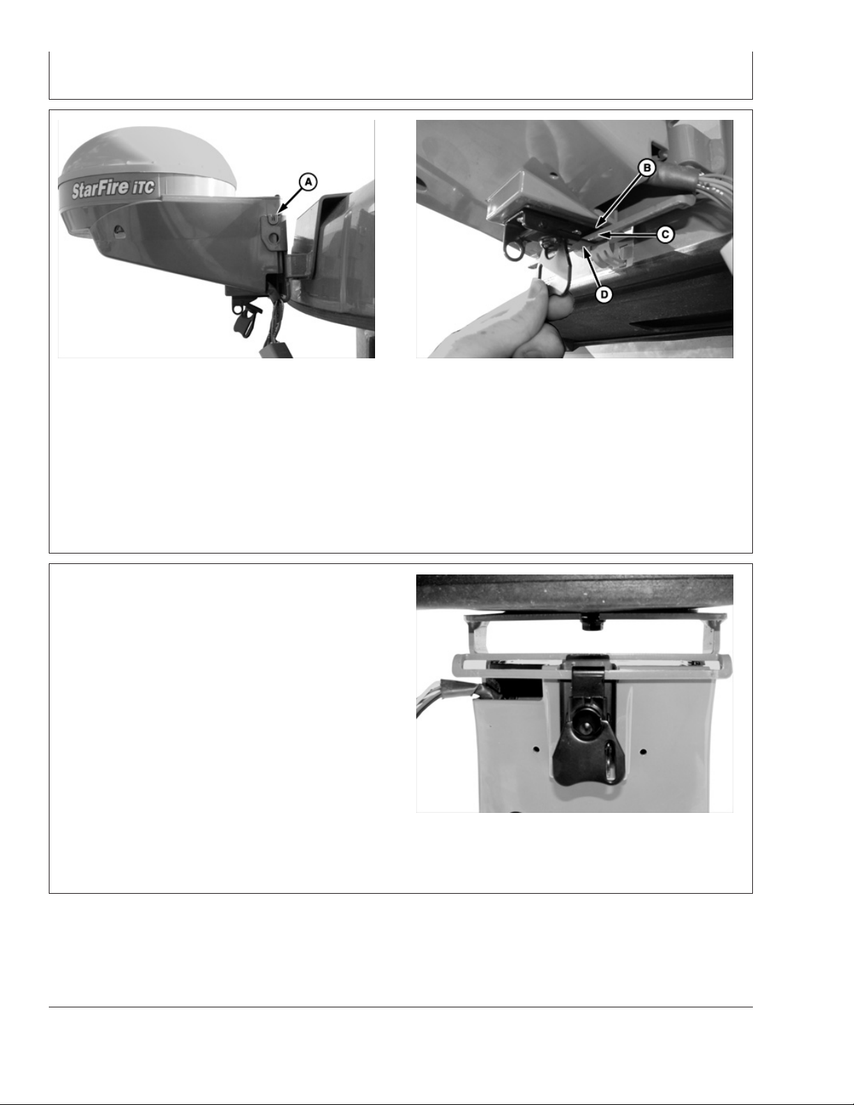
A—Mounting Peg B—Metal Tab C—Bracket Bar D—Receiver Latch
3. Position StarFire iTC on bracket. Align mounting
pegs (A) on receiver with notches in vehicle
bracket. Ensure pegs are firmly seated in notches
4. Position receiver latch (D) around bracket bar. Turn
latch handle to tighten latch around bracket bar.
Bracket bar should compress slightly.
and metal tab (B) is above bracket bar (C).
OUO6050,0000C0C –19–18OCT07–3/4
5. Fold latch handle upwards against receiver.
PC8329 –UN–31AUG04
10-2
PC8330 –UN–31AUG04
OUO6050,0000C0C –19–18OCT07–4/4
121907
PN=8
Page 9
GS2 Display—StarFire iTC
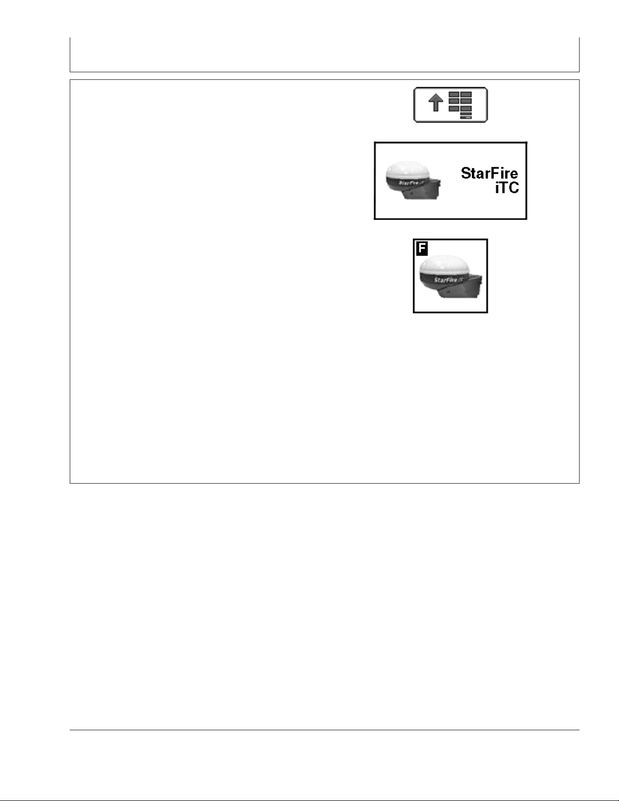
STARFIRE ITC softkey
The STARFIRE ITC - MAIN screen contains four tabs:
INFO tab
SETUP tab
ACTIVATIONS tab
SERIAL PORT tab
NOTE: If StarFire iTC is hooked into the CAN Bus with
an Original GreenStar display and either a
GSD2100 or 2600, the StarFire iTC will always be
displayed on the GSD2100 or 2600.
NOTE: If an Original StarFire receiver is hooked to a
GSD2100 or 2600, the setup and information
pages are displayed through Original GreenStar
Monitor. MENU >> ORIGINAL GREENSTAR
MONITOR. To view or change setup information,
SETUP >> STARFIRE RECEIVER. To view GPS
information INFO >> STARFIRE RECEIVER.
PC8663 –UN–05AUG05
PC8659 –UN–05AUG05
PC8680 –UN–05AUG05
MENU button
STARFIRE ITC button
STARFIRE ITC softkey
15-1
OUO6050,000223B –19–14NOV06–1/1
121907
PN=9
Page 10
INFO tab
GS2 Display—StarFire iTC
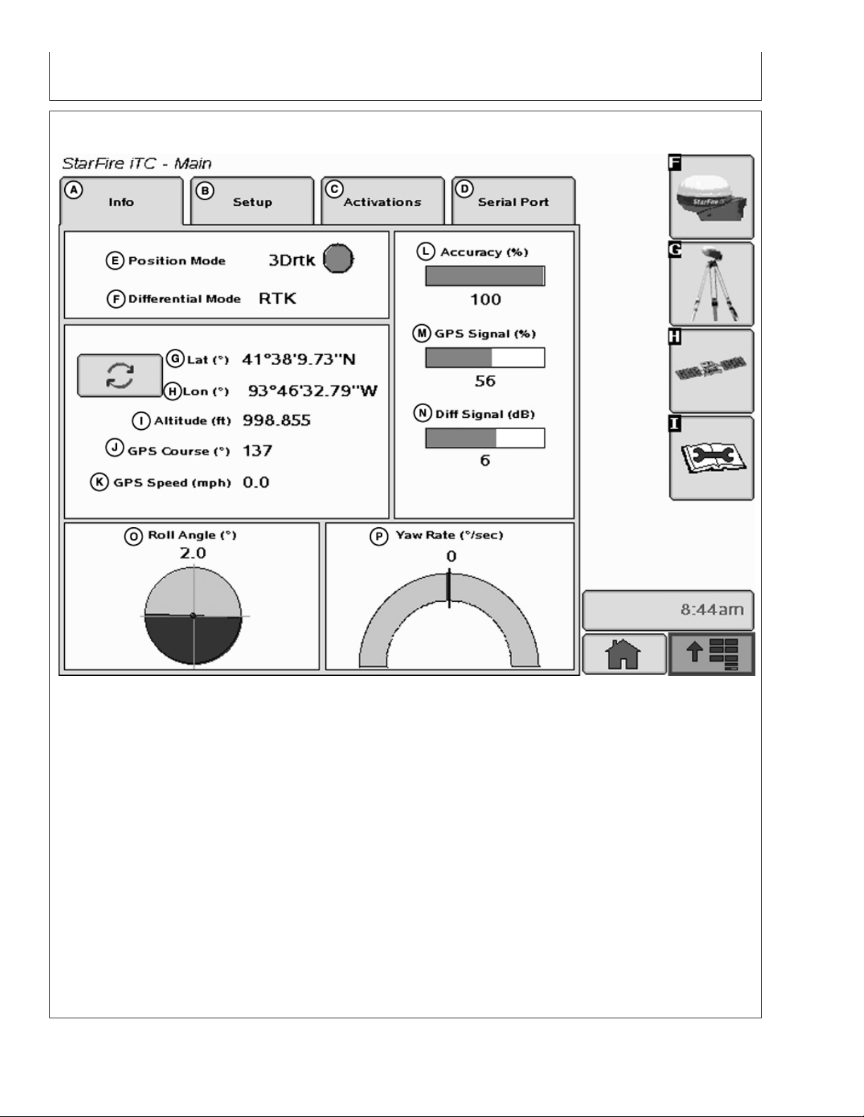
StarFire iTC - Main—Info Tab
A—Info tab E—Position Mode I—Altitude M—GPS Signal
B—Setup tab F—Differential Mode J—GPS Course N—Differential Signal
C—Activations tab G—Latitude K—GPS Speed O—Roll Angle
D—Serial Port tab H—Longitude L—Accuracy P—Yaw Rate
The INFO tab shows information and status of
incoming GPS and differential correction signals. No
information on this screen can be changed. It is for
viewing only:
• Differential Mode: Indicates status of GPS signal:
2-D (two dimensional with latitude and longitude of
vehicle) or 3-D (three dimensional with altitude,
latitude, and longitude of vehicle).
• Lat: Displays vehicle location latitude coordinates
• Position Mode: Indicates whether receiver is
calculating a 3D position, 2D position, or no position
(No Nav). It also shows status of differential signal:
with respect to Equator (north or south).
• Lon: Displays vehicle location longitude coordinates
with respect to Prim Meridian (east or west).
SF1 (StarFire 1 differential), SF2 (StarFire 2
differential).
Continued on next page
OUO6050,000223C –19–14NOV06–1/2
15-2
PC9705 –UN–10NOV06
121907
PN=10
Page 11

GS2 Display—StarFire iTC
NOTE: TOGGLE button allows operator to change the
way latitude and longitude are displayed from
degrees/minutes/seconds to decimal degrees.
• Altitude: displays height of receiver, measured from
top of dome, in feet (meters) above sea level.
• GPS course: Displays direction of travel, in degrees
relative to true north (zero degrees) as measured by
receiver. Angle is measured in clockwise direction
NOTE: Course and speed normally show small
speeds and various courses even when
machine is not moving.
• GPS speed: displays ground speed of machine in
miles per hour (kilometer per hour) as measured by
receiver.
• GPS Accuracy Indicator (GPS AI): GPS AI gives
indication of GPS position accuracy achieved by
receiver, and is displayed as a percentage (0-100%)
When receiver is initially powered, GPS AI will display
0%. As receiver acquires satellites and calculates a
position, GPS AI will increase as accuracy improves.
Acceptable guidance performance for Parallel Tracking
and AutoTrac is achieved when GPS AI displays 80%
or greater. This may take up to 20 minutes. GPS
accuracy is affected by many factors. If 80% accuracy
or greater is not achieved within 25 minutes, consider
the following possibilities:
• L1/L2 signal to noise ratio (SNR) – radio interference
from 2-way radios or other sources may cause low
SNR (check satellite button – Graph)
• Satellite position in sky – poor GPS satellite
geometry can reduce accuracy (check satellite
button – SkyPlot)
• Number of satellites above elevation mask – this is
the total number of GPS satellites available to
receiver that are above 7 degrees elevation mask
(check satellite button – SkyPlot).
• Number of satellites in solution – this is total number
of satellites that are being used by receiver to
calculate a position (check satellite button– SkyPlot).
• GPS Signal Quality: Displays quality of signals being
received from constellation of GPS satellites.
• Differential Signal Quality: Displays quality of
differential correction signal being received by
receiver.
• TCM (Terrain Compensation Module):
– Roll Angle: Is both a graphical and numerical
representation of amount of roll TCM is
measuring, relative to calibrated zero degree
reference. A positive roll angle means vehicle is
rolled to right (depicts what horizon would look
like from cab).
– Yaw Rate: This gives a graphic representation
and a numeric figure for amount of rotation TCM
is measuring. Positive yaw rate means vehicle is
turning to right.
• Unobstructed view of sky – trees, buildings, or other
structures may block receiver from receiver signals
from all available satellites.
15-3
OUO6050,000223C –19–14NOV06–2/2
121907
PN=11
Page 12
SETUP tab
GS2 Display—StarFire iTC
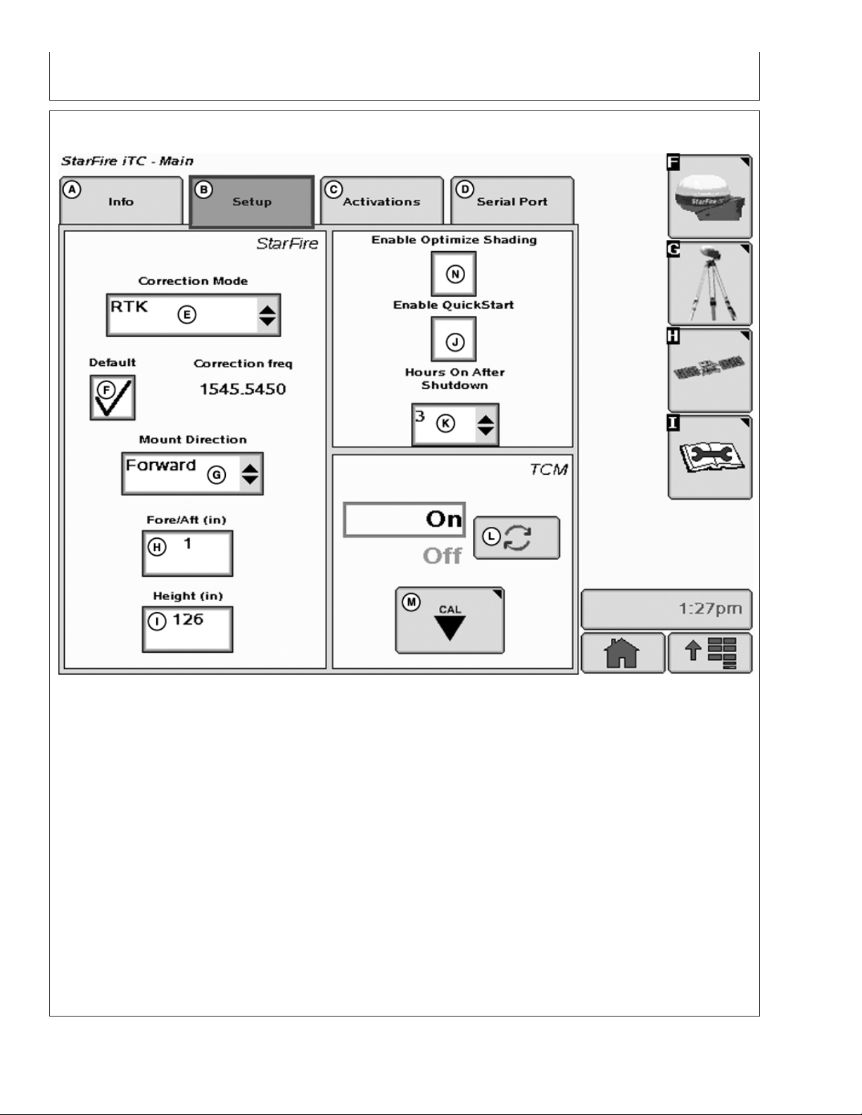
StarFire iTC - Main—Setup tab
A—Info tab E—Correction Mode H—Fore/Aft K—Hours On After Shutdown
B—Setup tab F—Default Correction I—Height L—TCM On/Off toggle button
C—Activations tab Frequency J—Enable QuickStart M—TCM Calibration button
D—Serial Port tab G—Mount Direction
The SETUP tab allows for setup of the following:
• Hours ON After Shutdown
• TCM Calibration
• Correction Mode
• Correction Frequency
• Mount Direction
• Fore/Aft
• Height
Differential correction is the process by which GPS
accuracy is improved. (See OVERVIEW: SF1/SF2
Activations, SF2 Subscription under Activations
section.)
• QuickStart
OUO6050,000223D –19–14NOV06–1/1
15-4
PC9706 –UN–17OCT07
121907
PN=12
Page 13

Correction Mode
GS2 Display—StarFire iTC
Contains available StarFire corrections that the
receiver is licensed for. SF1 and OFF will always
appear, however, SF2 will only appear with a valid
SF2 license (See Activations section). RTK appears
when a RTK mode is selected from RTK softkey.
Correction Frequency
This is the frequency that is used to receive differential
correction signals. The default frequency is a view only
field when default check box is checked. By
de-selecting default check box a correction frequency
can be manually entered.
NOTE: By selecting OFF, StarFire receiver will not
receive SF1 or SF2 correction signals, but will
receive WAAS/EGNOS correction signals.
OUO6050,000223E –19–14NOV06–1/1
IMPORTANT: DO NOT change default StarFire
Correction Frequency unless
instructed to do so by a John Deere
Dealer or by John Deere AG
Management Solutions.
OUO6050,000223F –19–14NOV06–1/1
Mount Direction
NOTE: Receivers attached to tractors, sprayer, and
combines are typically in FORWARD position.
Receivers attached to GATORS are typically in
BACKWARD position.
Mounting direction is direction receiver is facing.
This setting defines mounting orientation of receiver.
TCM uses this setting to determine correct direction of
vehicle roll.
Mounting direction options
• FORWARD
• BACKWARD
Select desired mounting direction.
OUO6050,0002240 –19–14NOV06–1/1
15-5
121907
PN=13
Page 14
Fore/Aft
GS2 Display—StarFire iTC
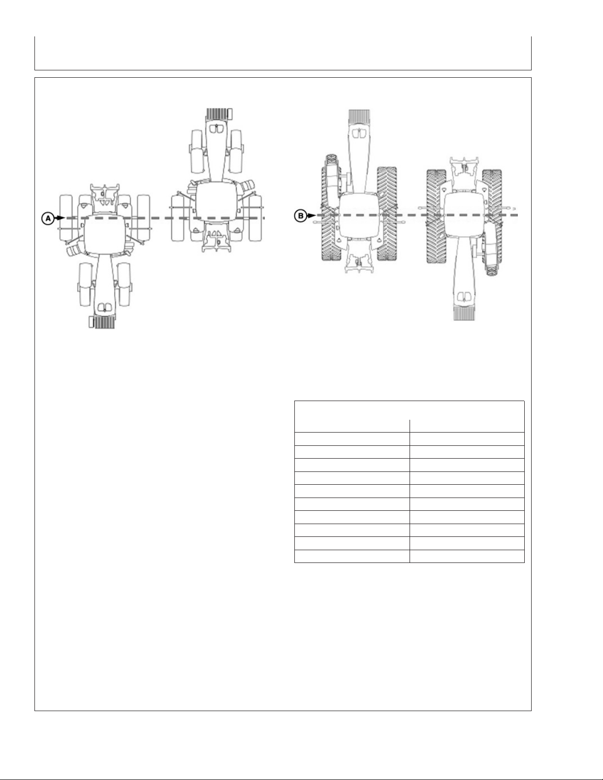
Floating Front Axle Vehicles
A—Pivot Point—Floating Front B—Pivot Point—-Fixed Axis
Axle Vehicles- Wheels or Tracks Vehicles
The fore/aft value is the distance that receiver is
located from pivot point of tractor.
On some AutoTrac-equipped vehicles, fore/aft value
will be automatically detected and entered during
power up.
• Fore/Aft value is shown and input box is disabled –
value has been automatically set and cannot be
changed. The value shown may not be the exact
distance that the receiver is located from pivot point
of tractor, but the best Fore/Aft value for AutoTrac.
• Fore/Aft value is shown and input box is enabled –
value must be entered manually.
To enter Fore/Aft value:
• Select FORE/AFT input box
PC8278 –UN–22JUN04
Fixed Axis Wheels or Tracks Vehicles
• Enter value using numeric keypad
Recommended StarFire Fore/Aft values For John Deere
Vehicles
John Deere Vehicle StarFire Fore/Aft cm (in.)
6000 Series Tractors 180 cm (71 in.)
7000 Series Tractors 210 cm (82.5 in.)
8000 Series Tractors 210 cm (82.5 in.)
8000T Series Tractors 51 cm (20 in.)
9000 Series Tractors -51 cm (-20 in.)
9000T Series Tractors 51 cm (20 in.)
4700 Series Sprayers 280 cm (110 in.)
4900 Series Sprayers 460 cm (181 in.)
Combine 220 cm (87 in.)
Forage Harvester 157 cm (62 in.)
PC8277 –UN–01MAY06
15-6
OUO6050,0002241 –19–25NOV06–1/1
121907
PN=14
Page 15

Height
GS2 Display—StarFire iTC
Height is measured from ground to top of StarFire
Dome. Select input box and use numeric keypad to
enter height.
IMPORTANT: Under or over compensation for
vehicle roll angles will occur if
height is incorrectly entered during
setup.
Example: On a 10 degree slope with
a StarFire height error of 30.5 cm (12
in.) will result in a position offset of
5 cm (2 in.) on ground).
Factory default setting is “126”. On
some AutoTrac-equipped vehicles,
height value will be automatically
detected and entered during power
up. Because this dimension is
critical for proper operation of TCM
and can vary due to vehicle
configuration and tire sizes, operator
should still measure actual distance
to be entered each time TCM is
installed on a different vehicle.
NOTE: Use chart for example StarFire Height values.
Chart figures are approximate heights.
John Deere Vehicle StarFire Height cm (in.)
6000 Series Tractors 280 cm (111 in.)
7000 Series Tractors 305 cm (120 in.)
8000 Series Tractors 320 cm (126 in.)
8000T Series Tractors 320 cm (126 in.)
9000 Series Tractors 361 cm (142 in.)
9000T Series Tractors 356 cm (140 in.)
4700 Series Sprayers 389 cm (153 in.)
4900 Series Sprayers 396 cm (156 in.)
Combine 396 cm (156 in.)
NOTE: Actual height may vary depending on tire size
or inflation.
QuickStart
Reduces amount of time required before full accuracy
is achieved. If QuickStart is enabled (check box
checked) and receiver has SF1 or SF2 when it is
powered down a position is saved for future
QuickStart. If power is restored to receiver within time
period defined under Hours On After Shutdown,
QuickStart won’t be needed since receiver power was
never disrupted. If duration has exceeded Hours On
After Shutdown, QuickStart will be initiated. Saved
OUO6050,0002242 –19–14NOV06–1/1
position will be used to bypass startup warm up period
that is usually required. Receiver cannot move while
this QuickStart is taking place. It may take up to 6
minutes for QuickStart to complete. User will be
notified on screen when it is done.
To enable QuickStart mode select check box so that a
check appears. To disable, select check box until
check disappears.
OUO6050,0002243 –19–14NOV06–1/1
15-7
121907
PN=15
Page 16
Hours On After Shutdown
GS2 Display—StarFire iTC
Defines how long receiver remains powered up after
ignition is turned off (0, 3, 6, 12, 24 hours). If ignition is
turned on within number of hours defined, receiver will
re-establish full SF1 or SF2 accuracy within a few
seconds (assuming it had SF1 or SF2 when ignition
was turned off).
TCM Calibration
Define desired number of hours by selecting
drop-down box.
OUO6050,0002244 –19–14NOV06–1/1
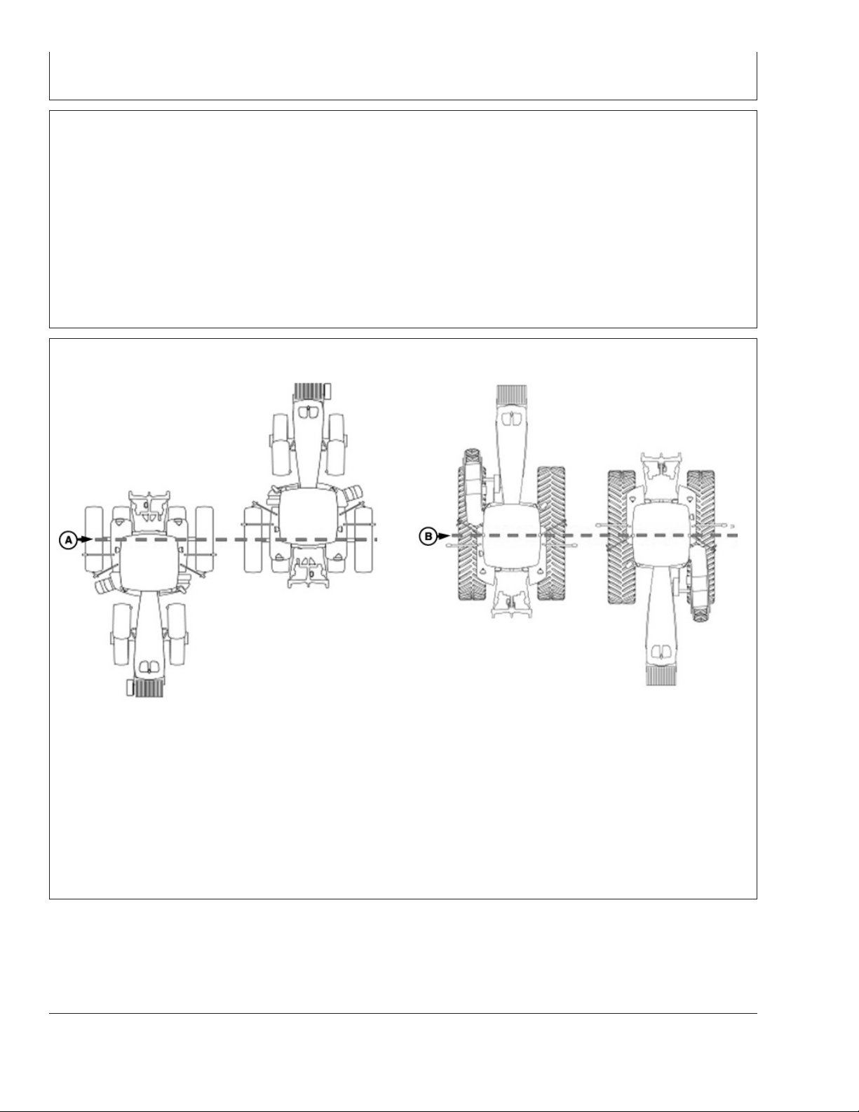
Floating Front Axle Vehicles
A—Rear Axle B—Vehicle Pivot Point
TCM can be toggled ON or OFF by selecting TOGGLE
button. When TCM is turned off, StarFire GPS
message will not be corrected for vehicle dynamics or
side slopes. TCM will default to ON when cycling
power.
PC8278 –UN–22JUN04
Fixed-Axis Wheels Or Tracks Vehicles
NOTE: TCM must be turned on for AutoTrac to
activate.
TCM must be calibrated so receiver can determine
zero degree roll angle.
Continued on next page
OUO6050,0002245 –19–14NOV06–1/4
15-8
PC8277 –UN–01MAY06
121907
PN=16
Page 17

GS2 Display—StarFire iTC
NOTE: Calibrate receiver when it is attached or
reattached to machine. Receiver does not
require recalibration until removed from
machine and reattached.
Positioning Machine during Calibration
IMPORTANT: When calibrating, it is important that
TCM is at same angle when facing
either direction. If roll angle is a
positive 2 degrees when facing one
direction, vehicle needs to be a
negative 2 degrees when facing
opposite direction. To position TCM
at same angle it is important when
turning vehicle around and facing
other direction that tires are placed
in correct location. Once vehicle is
parked on a hard flat surface, note
location of tires on ground. When
turning around use following
instructions:
• Floating Front Axle Vehicles
(MFWD, ILS, TLS)—put rear
axle/wheels in same location when
performing 2 point calibration. See
above diagram for Floating Front
Axle Vehicles.
• Fixed-Axis Wheels Or Tracks
Vehicles (Track Tractors, 47X0 and
49X0 Series Sprayers, 9000, And
9020 Series Wheel Tractors)—
Place all in same location when
facing either direction. See above
diagram for Fixed-Axis Wheels Or
Tracks Vehicles.
Continued on next page
OUO6050,0002245 –19–14NOV06–2/4
15-9
121907
PN=17
Page 18
GS2 Display—StarFire iTC
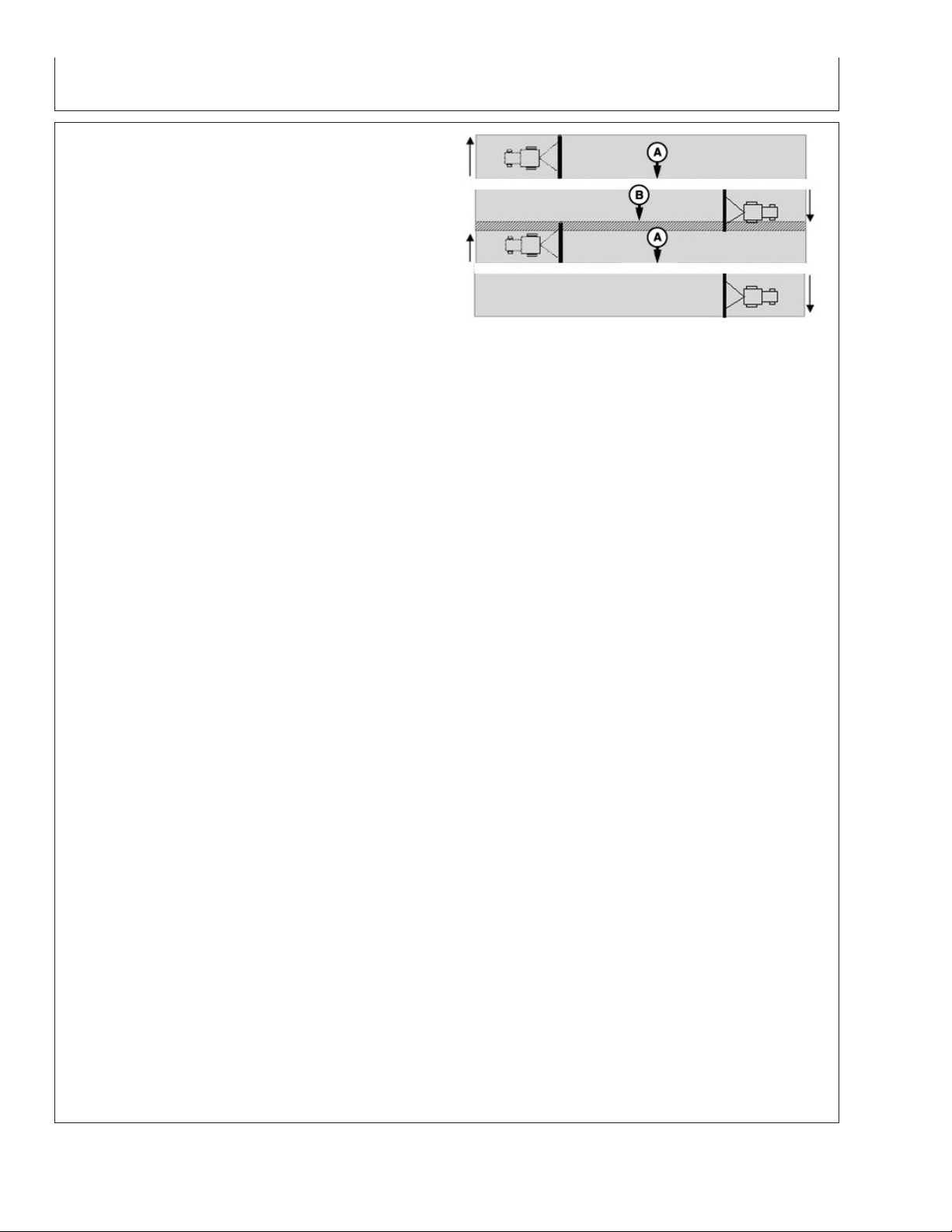
Calibration Surface
IMPORTANT: Vehicle must be on a hard, flat level
surface for calibration. If TCM is not
calibrated on a level surface or TCM
mounting angle is not level in relation
to vehicle angle (StarFire mounting
bracket or vehicle cab being slightly
offset, uneven tire pressures from one
side to other, etc.) operator may see
offset during operation. This offset
could look like a consistent skip (A) or
overlap (B) in pass-to-pass operation.
To eliminate offset, re-calibrate on a
level surface, drive down a pass, turn
around and drive down same pass in
opposite direction. If vehicle does not
follow same pass, measure offset
distance and enter in implement offset.
After initial calibration of TCM, it is not
necessary to calibrate again unless
TCM angle in relation to vehicle has
changed. For example, tire pressure has
been lowered on one side of vehicle
causing vehicle angle in relation to
ground to change.
PC8279 –UN–16JUL04
A—Skip
B—Overlap
Calibration Procedure:
1. Press CALIBRATION button.
2. Park vehicle on a hard, level surface and come to a
complete stop (cab is not rocking).
3. Press ENTER button.
4. Calibrating Status bar will appear. Once status reaches
100% it will automatically advance.
5. Turn vehicle 180 degrees to face opposite direction.
Ensure that tires are in proper location for fixed or
floating front axle and vehicle has come to a complete
stop (cab is not rocking).
6. Press ENTER CALIBRATION button.
7. Calibrating Status bar will appear. Once status reaches
100% it will automatically advance.
8. Once finished, a calibration value will be displayed. 0
degree calibration value is the difference between
factory calibration value and actual calibration value
which was just determined.
Continued on next page
15-10
OUO6050,0002245 –19–14NOV06–3/4
121907
PN=18
Page 19

GS2 Display—StarFire iTC
9. Press ENTER button to return to SETUP tab.
OUO6050,0002245 –19–14NOV06–4/4
15-11
121907
PN=19
Page 20
ACTIVATIONS tab
GS2 Display—StarFire iTC
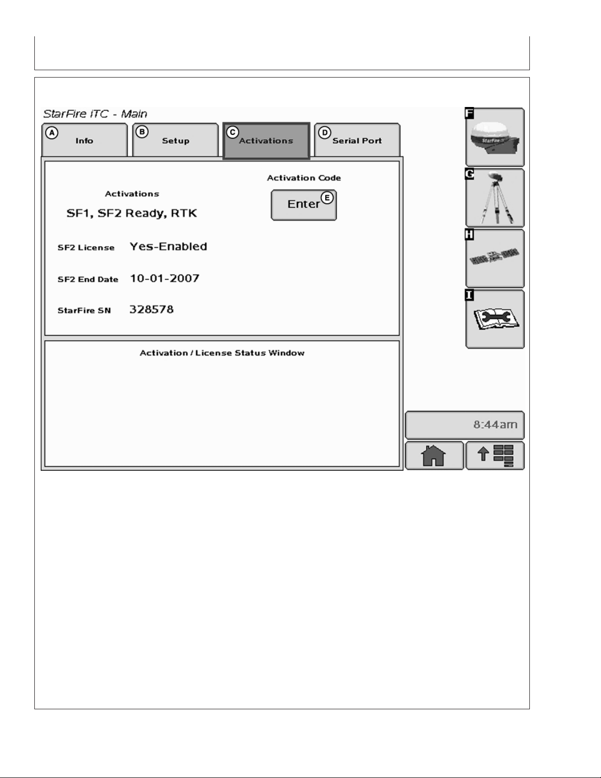
StarFire iTC - Main—Activations tab
A—Info tab C—Activations tab D—Serial Port tab E—Activation Code Enter
B—Setup tab button
ACTIVATIONS tab contains the following:
– Yes-Enabled – A valid SF2 license exists and SF2
is the differential correction mode selected.
• Valid activations for receiver:
– SF1 – activated on every StarFire iTC.
– SF2 Ready – receiver has to be ordered SF2
Ready or an upgrade to SF2 ready from SF1
World Solution must be purchased.
– RTK – activated with valid RTK activation
(requires receiver to be SF2 Ready).
• SF2 License: Displays status of receiver’s SF2
– Yes-Disabled – A valid SF2 license exists, but
SF2 is not the differential correction mode
selected.
– No – Appears when no valid SF2 license exists or
SF2 license has expired.
• SF2 End Date: Displays date at which SF2 License
will expire.
• StarFire SN: StarFire serial number
License.
Continued on next page
OUO6050,0002246 –19–14NOV06–1/3
15-12
PC9707 –UN–10NOV06
121907
PN=20
Page 21
GS2 Display—StarFire iTC
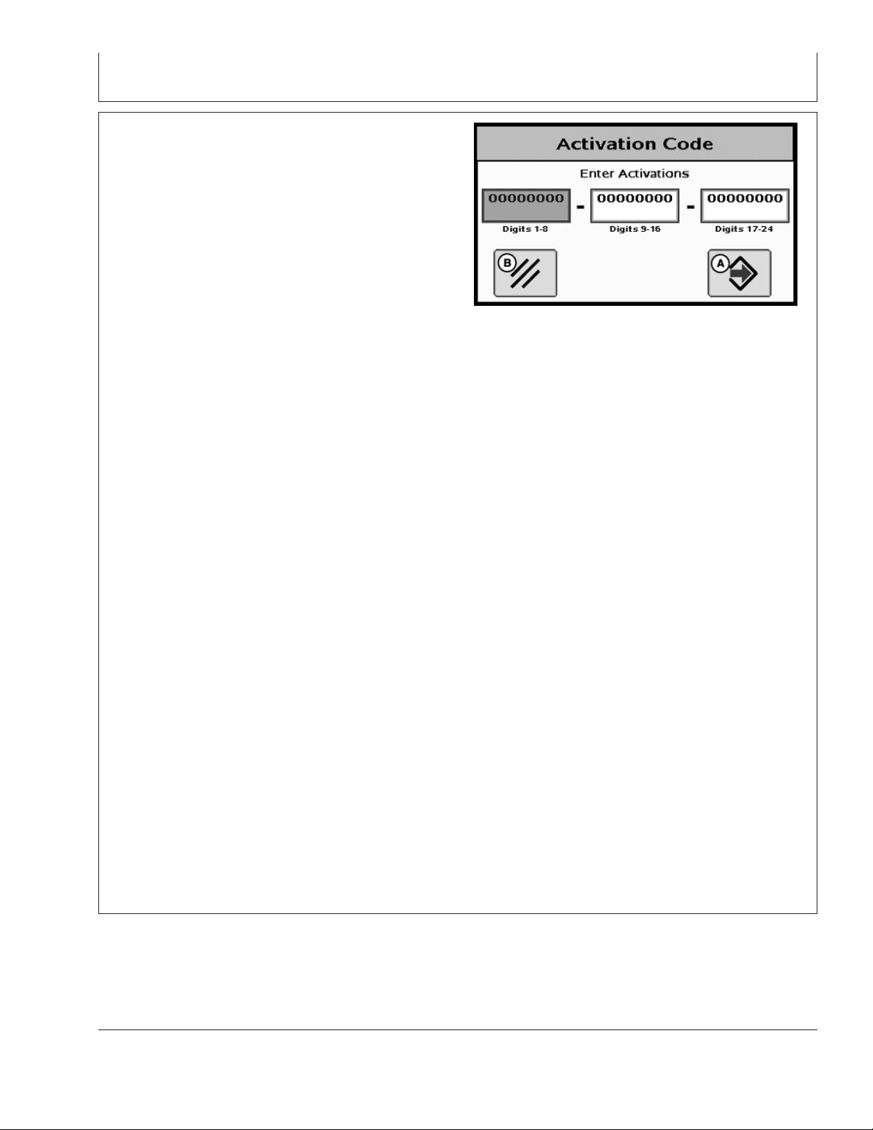
Activation Code
NOTE: Activation Codes are needed to obtain SF2 Ready
and RTK Activations, and SF2 license
subscription.
ENTER button is used to enter 24-digit codes for SF2
Ready and RTK Activations, SF2 license subscription and
deactivation codes for transferring all StarFire activations
and licenses mentioned above.
1. Upon selecting ENTER button an Activation Code box
appears with three input boxes.
NOTE: If more than 8 digits are entered into an input box,
“99999999” will appear. Reselect box and type
only 8 digits into input box.
2. Select first input box labeled Digits 1-8 and enter first 8
digits of 24-digit code.
3. Select second input box labeled Digits 9-16 and enter
second 8 digits of 24-digit code.
4. Select third input box labeled Digits 17-24 and enter
last 8 digits of 24 digit code.
5. Press ENTER button.
6. If 24-digit code is valid and entered correctly a
confirmation message will appear.
Activation Code
PC9708 –UN–10NOV06
A—Enter button
B—Cancel button
7.Deactivation Code input
This input will only appear when a deactivation code has
been entered following procedure listed above. It will
display 6-digit deactivation codes for SF2 License, SF2
Ready and RTK activations. These codes are needed
when transferring the above mentioned activations or
license to another receiver.
Activation/License Status Window
Displays messages when SF2 License has expired and
provides user with option to use a Grace Period.
Continued on next page
OUO6050,0002246 –19–14NOV06–2/3
15-13
121907
PN=21
Page 22

GS2 Display—StarFire iTC
NOTE: Three 24 hour Grace periods are available when
current license expires. This is provided to allow
sufficient time for operator to renew a license.
Grace period signal will be SF2 differential
correction signal.
Using a Grace Period
1. Select USE 1 button from status window
2. Select YES button
OUO6050,0002246 –19–14NOV06–3/3
15-14
121907
PN=22
Page 23
SERIAL PORT tab
GS2 Display—StarFire iTC
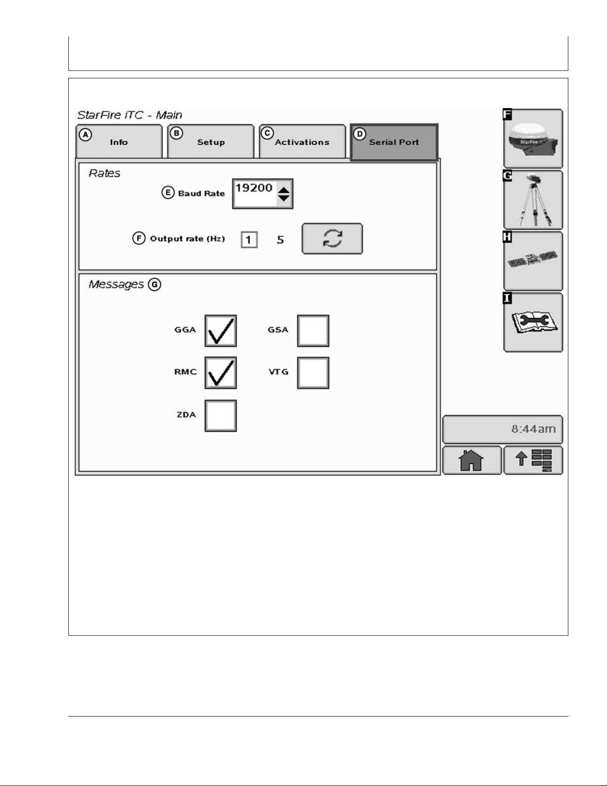
StarFire iTC - Main—Serial Port tab
A—Info tab C—Activations tab E—Baud Rate G—Messages
B—Setup tab D—Serial Port tab F—Output Rate
Configure RS232 and NMEA message information.
• Define output rate by toggling
– 1Hz or 5Hz
Rates:
• Define Baud Rate by selecting list input
– Baud Rates: 4800, 9600, 19200, 38400
Messages:
• Allows for output of 5 different NMEA strings:
– GGA, GSA, RMC, VTG, and ZDA
OUO6050,0002247 –19–14NOV06–1/1
15-15
PC9709 –UN–25SEP07
121907
PN=23
Page 24

GS2 Display—StarFire iTC
NMEA Strings
NMEA String Data – Utilizing a third party GPS receiver or
utilizing a StarFire iTC
National Marine Electronics Association (NMEA) has
developed a specification that defines the interface
between various pieces of electronic equipment.
One of the most important NMEA sentences include the
GGA which provides the current Fix data, the RMC which
provides the minimum GPS sentences information, and
the GSA which provides the Satellite status data.
GGA - essential fix data which provide 3D location and
accuracy data.
GGA STRING EXAMPLE:
$GPGGA,123519,4807.038,N,01131.000,E,
1,08,0.9,545.4,M,46.9,M,,*47
Where:
GGA Global Positioning System Fix Data
123519 Fix taken at 12:35:19 UTC
4807.038,N Latitude 48 deg 07.038’ N
01131.000,E Longitude 11 deg 31.000’ E
1 Fix quality:
08 Number of satellites being tracked
0.9 Horizontal dilution of position
545.4,M Altitude, Meters, above mean sea level
46.9,M Height of geoid (mean sea level) above WGS84
0 = invalid
1 = GPS fix (SPS)
2 = DGPS fix
3 = PPS fix
4 = Real Time Kinematic
5 = Float RTK
6 = estimated (dead reckoning)
7 = Manual input mode
8 = Simulation mode
Continued on next page
15-16
OUO6050,0000ED9 –19–07NOV07–1/4
121907
PN=24
Page 25

GS2 Display—StarFire iTC
GSA - GPS DOP and active satellites. This sentence
provides details on the nature of the satellite constellation
fix. It includes the numbers of the satellites being used in
the current solution and the DOP. DOP (dilution of
precision) is an indication of the effect of satellite
geometry on the accuracy of the fix. It is a unitless
number where smaller is better. For 3D fixes using 4
satellites a 1.0 would be considered to be a perfect
number, however for overdetermined solutions it is
possible to see numbers below 1.0.
There are differences in the way the PRN’s are presented
which can effect the ability of some programs to display
this data. For example, in the example shown below there
are 5 satellites in the solution and the null fields are
scattered indicating that the almanac would show
satellites in the null positions that are not being used as
part of this solution. Other receivers might output all of the
satellites used at the beginning of the sentence with the
null field all stacked up at the end. This difference
accounts for some satellite display programs not always
being able to display the satellites being tracked. Some
units may show all satellites that have ephemeris data
without regard to their use as part of the solution but this
is non-standard.
GSA String Example
$GPGSA,A,3,04,05,,09,12,,,24,,,,,2.5,1.3,2.1*39
Where:
GSA Satellite status
A Auto selection of 2D or 3D fix (M = manual)
3 3D fix - values include::
04,05 PRNs of satellites used for fix (space for 12)
2.5 PDOP (dilution of precision)
1.3 Horizontal dilution of precision (HDOP)
2.1 Vertical dilution of precision (VDOP)
*39 the checksum data, always begins with *
1=nofix
2=2Dfix
3=3Dfix
Continued on next page
15-17
OUO6050,0000ED9 –19–07NOV07–2/4
121907
PN=25
Page 26

GS2 Display—StarFire iTC
RMC - NMEA has its own version of essential gps pvt
(position, velocity, time) data. It is called RMC, The
Recommended Minimum, which will look similar to:
RMC String Example
$GPRMC,123519,A,4807.038,N,01131.000,
E,022.4,084.4,230394,003.1,W*6A
Where:
RMC Recommended Minimum sentence C
123519 Fix taken at 12:35:19 UTC
A Status A=active or V=Void.
4807.038,N Latitude 48 deg 07.038’ N
01131.000,E Longitude 11 deg 31.000’ E
022.4 Speed over the ground in knots
084.4 Track angle in degrees True
230394 Date - 23rd of March 1994
003.1,W Magnetic Variation
*6A The checksum data, always begins with *
VTG - Velocity made good. The gps receiver may use the
LC prefix instead of GP if it is emulating Loran output.
VTG String Example
$GPVTG,054.7,T,034.4,M,005.5,N,010.2,K*33
where:
VTG Track made good and ground speed
054.7,T True track made good (degrees)
034.4,M Magnetic track made good
005.5,N Ground speed, knots
010.2,K Ground speed, Kilometers per hour
*33 Checksum
ZDA - Data and Time
ZDA String Example
$GPZDA,hhmmss.ss,dd,mm,yyyy,xx,yy*CC
$GPZDA,201530.00,04,07,2002,00,00*6E
Continued on next page
15-18
OUO6050,0000ED9 –19–07NOV07–3/4
121907
PN=26
Page 27
GS2 Display—StarFire iTC
where:
hhmmss HrMinSec(UTC)
dd,mm,yyy Day,Month,Year
xx local zone hours -13..13
yy local zone minutes 0..59
*CC checksum
SATELLITE INFORMATION softkey
Press: MENU button >> STARFIRE ITC button >>
SATELLITE INFORMATION softkey.
The StarFire iTC - Satellite Information screen contains
SKY PLOT and GRAPH tabs.
PC8663 –UN–05AUG05
PC8659 –UN–05AUG05
OUO6050,0000ED9 –19–07NOV07–4/4
MENU button
PC8682 –UN–05AUG05
SATELLITE INFORMATION softkey
Continued on next page
STARFIRE ITC button
OUO6050,0002248 –19–14NOV06–1/4
15-19
121907
PN=27
Page 28
GS2 Display—StarFire iTC
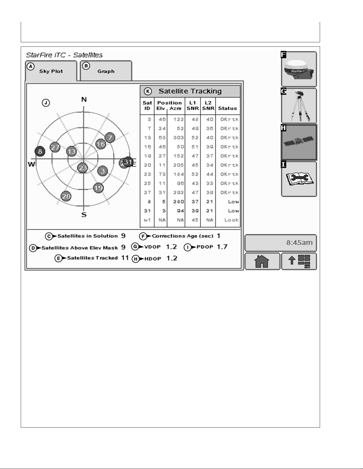
StarFire iTC - Satellites
A—Sky Plot tab D—Satellites Above Elevation F—Corrections Age I—PDOP
B—Graph tab Mask G—VDOP J—Satellites on Sky Plot
C—Satellites in Solution E—Satellites Tracked H—HDOP K—Satellite Tracking
SKY PLOT tab
– Green – indicates satellite is OK (being used for
corrections)
Illustrates where satellites are in relation to vehicles
receiver. This allows operator to look at satellite
geometry.
• Sky Plot consists of 3 concentric rings depicting 0,
30, and 60 degrees of elevation with directional
crossbar intersection representing 90 degrees of
elevation.
Reading Satellite Sky Plot
• Grey radial lines extending from center of Sky Plot
represent azimuth. They are spaced 30 degrees
• Sky Plot is fixed so that North is always at top.
• Satellites are displayed as their satellite ID number
that correspond to Satellite Tracking Chart located
right of Sky Plot
– Red – indicates satellite is in search mode
– Blue – indicates satellite is being tracked
apart and represent 30 and 60 degrees.
• Directional crossbar representing North, South, East,
and West also represent azimuth at 0, 90, 180, and
270 degrees.
• W1 and W2 (WAAS/EGNOS) satellites and inmarsat
satellites are not shown in Sky Plot.
Continued on next page
OUO6050,0002248 –19–14NOV06–2/4
15-20
PC9711 –UN–10NOV06
121907
PN=28
Page 29

GS2 Display—StarFire iTC
Satellite Tracking Chart
• SAT ID – (Satellite Identification Number)
Identification number for GPS Satellite.
• ELV – (Position Elevation) Elevation in degrees
above horizon for GPS satellite position
• AZM – (Position Azimuth) Azimuth in degrees from
true North for GPS satellite
• L1 SNR – (L1 Signal to Noise Ratio) Signal strength
for L1 GPS signal (signal to noise ratio)
• L2 SNR – (L2 Signal to Noise Ratio) Signal strength
for L2 GPS signal (signal to noise ratio)
• Status – (GPS Signal Status) Status of GPS signal
– Search – searching for satellite signal
– Track – tracking satellite signal and using it for
positioning
– OK – tracking satellite signal and using it for
positioning
– OK SF1 – Tracking satellite signal and using it for
positioning with STARFIRE single frequency
– OK SF2 – Tracking satellite signal and using it for
positioning with STARFIRE dual frequency
Satellite Tracking Information
Satellite Tracking information is displayed at bottom of
SKY PLOT and GRAPH tabs.
• Satellites in Solution – number of satellites used to
compute position.
• Satellites Above Elevation Mask – total number of
GPS satellites available to receiver that are above 7
degree elevation mask.
• Satellites Tracked – total number of GPS satellites
tracked by receiver.
• Corrections Age (sec) – age of differential correction
signal to GPS (normally less than 10 seconds)
• VDOP – Vertical Dilution of Precision
• HDOP – Horizontal Dilution of Precision
• PDOP – Positional Dilution of Precision is an
indicator of GPS satellite geometry as viewed by
receiver. A lower PDOP indicates better satellite
geometry for calculating both horizontal and vertical
position.
Continued on next page
OUO6050,0002248 –19–14NOV06–3/4
15-21
121907
PN=29
Page 30
GS2 Display—StarFire iTC
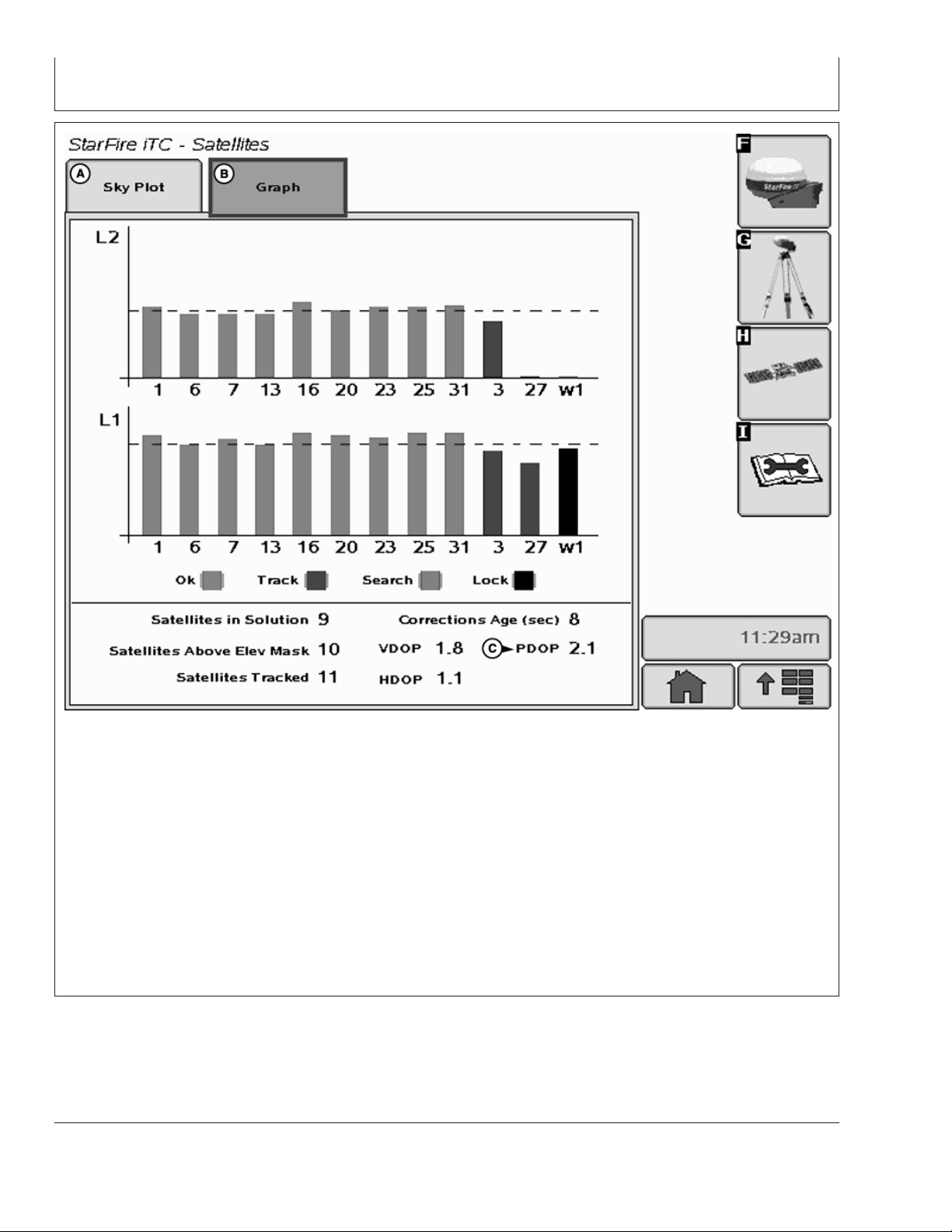
StarFire iTC - Satellites
A—SkyPlot B—Graph C—PDOP
Graph
A graph illustrating L1 and L2 SNR values.
• Bars are colored to satellites current status.
• SNR values (colored bar) should be above dashed
line that runs horizontally across bar graph.
NOTE: ONLY GREEN bars are used in calculation of
PDOP, VDOP, AND HDOP. SNR’s are
considered good if above dashed line.
OUO6050,0002248 –19–14NOV06–4/4
15-22
PC9551 –UN–06NOV06
121907
PN=30
Page 31

Satellite Predictor
GS2 Display—StarFire iTC
Quality
PDOP
NOTE: This is an estimated prediction of your GPS
coverage
Satellite PREDICTOR will enable operator to plan out
the day based upon the prediction of GPS accuracy.
This only applies to the Color GS2 display.
PC10336E –UN–11SEP07
# Sats
PC10336G –UN–11SEP07
VDOP
Satellite PREDICTOR shows a prediction of GPS
accuracy. for one day in the past, the current day, and
one day in the future. The current location will be used
for the prediction.
PC10336F –UN–11SEP07
PC10336H –UN–11SEP07
Continued on next page
15-23
OUO6050,0000DAE –19–18OCT07–1/2
121907
PN=31
Page 32

GS2 Display—StarFire iTC
Satellite PREDICTOR uses three colors to represent
levels of GPS accurancy.
• Green = PDOP < =2.5 and VDOP <=2.0 with 7 or
more satellites
DIAGNOSTIC softkey
The StarFire iTC - Diagnostic screen contains three tabs:
READINGS tab
DATA LOGS tab
READINGS tab has detailed information about receiver.
• Unswitched voltage
• Switched voltage
• CAN High voltage (Vehicle Bus)
• CAN Low voltage (Vehicle Bus)
• Software Part Number
• Software Version Number
• Hardware Part Number
• Hardware Serial Number
• Receiver Hours (h)
• Yellow = PDOP between 2.5 and 4.0 and VDOP
between 2.0 and 3.0 with 5 to 6 satellites
• Red = PDOP > =4.0 and VDOP >=3.0 or number of
satellites is < 4
OUO6050,0000DAE –19–18OCT07–2/2
PC8663 –UN–05AUG05
PC8659 –UN–05AUG05
PC8683 –UN–05AUG05
MENU button
STARFIRE ITC button
The following reading will only appear when receiver has
a RTK activation.
• RTK Software Number (RTK Radio Software Version)
• RTK Serial Number (RTK Radio Serial Number)
• RTK Status
• RTK Search Time (sec)
• RTK Satellites in Search (above 10 degrees elevation)
DATA LOGS tab has graphed GPS data, logged over the
previous 60 minutes.
15-24
DIAGNOSTIC softkey
OUO6050,0002249 –19–14NOV06–1/1
121907
PN=32
Page 33

READINGS tab
GS2 Display—StarFire iTC
StarFire iTC - Diagnostics
A—Readings tab E—Switched Voltage J—Hardware Part Number N—RTK Serial Number
B—Data Logs tab F—CAN High Voltage K—Hardware Serial Number O—RTK Status
C—Radio Self Test tab (North G—CAN Low Voltage L—Receiver Hours P—RTK Search Time
America Only) H—Software Part Number M—RTK Software Version Q—RTK Satellites in Search
D—Unswitched Voltage I—Software Version Number Number
OUO6050,000224A –19–19NOV06–1/1
15-25
PC9712 –UN–10NOV06
121907
PN=33
Page 34

DATA LOGS tab
GS2 Display—StarFire iTC
A—Readings tab B—Data Logs tab C—Radio Self Test tab
GPS Accuracy is a relative indication of overall
differential GPS performance
StarFire iTC - Diagnostic
Continued on next page
15-26
PC9588 –UN–09NOV06
OUO6050,0000C1D –19–23SEP07–1/7
121907
PN=34
Page 35

GS2 Display—StarFire iTC
StarFire iTC - Diagnostic
A—Readings tab B—Data Logs tab C—Radio Self Test tab
PDOP (Position Dilution of Precision) is a combination
of vertical and horizontal error (or three dimensional).
Lower PDOP is better. A value below 2 is considered
optimal.
Continued on next page
OUO6050,0000C1D –19–23SEP07–2/7
15-27
PC9589 –UN–09NOV06
121907
PN=35
Page 36

GS2 Display—StarFire iTC
StarFire iTC - Diagnostic
A—Readings tab B—Data Logs tab C—Radio Self Test tab
Satellites in Solution is the number of satellites that
receiver is using in current position solution. Satellites
are not used in solution until they get above 7 degrees
elevation mask for EGNOS, SF1, or SF2 (10 degrees
for RTK), and satellites are used until they drop below
7 degrees elevation mask for EGNOS, SF1, SF2 or
RTK.
Continued on next page
OUO6050,0000C1D –19–23SEP07–3/7
15-28
PC9590 –UN–09NOV06
121907
PN=36
Page 37

GS2 Display—StarFire iTC
StarFire iTC - Diagnostic
A—Readings tab B—Data Logs tab C—Radio Self Test tab
GPS Signal Quality shows quality of signals being
received from GPS satellites. Unlike GPS Accuracy
Indicator, Signal Quality doesn’t include EGNOS, SF1,
SF2 or amount of time signal is received.
Continued on next page
OUO6050,0000C1D –19–23SEP07–4/7
15-29
PC9591 –UN–09NOV06
121907
PN=37
Page 38

GS2 Display—StarFire iTC
StarFire iTC - Diagnostic
A—Readings tab B—Data Logs tab C—Radio Self Test tab
Differential Signal Quality is the strength of StarFire
network signal (SF2 or SF1). Normal range is from 5
to 15, but maximum reading on indicator is 10.
Numerical value is displayed to right of indicator. Any
value above 5 is normal.
Continued on next page
OUO6050,0000C1D –19–23SEP07–5/7
15-30
PC9592 –UN–09NOV06
121907
PN=38
Page 39

GS2 Display—StarFire iTC
StarFire iTC - Diagnostic
A—Readings tab B—Data Logs tab C—Radio Self Test tab
Navigation Mode is represented as three different
types; No Nav, 2D and 3D. This helps determine if
GPS position has been dropped in last 60 minutes.
Continued on next page
15-31
PC9593 –UN–09NOV06
OUO6050,0000C1D –19–23SEP07–6/7
121907
PN=39
Page 40

GS2 Display—StarFire iTC
StarFire iTC - Diagnostic
A—Readings tab B—Data Logs tab C—Radio Self Test tab
Differential Mode shows the level of differential signal
that receiver has received over past 60 minutes. Level
of signal that was purchased on receiver will determine
highest point on bar graph that operator will see.
OUO6050,0000C1D –19–23SEP07–7/7
15-32
PC9594 –UN–17OCT07
121907
PN=40
Page 41

Radio Self Test
GS2 Display—StarFire iTC
StarFire iTC - Diagnostics
EU Radio Self Test Page STRING SHOWN DESCRIPTION
• (A) Number of updates - Number of test cycles that
the Self Test page has performed. During each cycle
the test parameters are requested and updated from the
radio.
• (B) Frequency - Radio Frequency (MHz)
• (C) Serial Number - Radio Serial Number
• (D) Part Number - Part number that identifies an RTK
radio type: “JD3AS869" is a 869 MHz radio with 0.5
Watt power
• (E) Software Version - Radio Software Version
• (F) Time Slot - Radio Time Slot
• (G) Repeater Mode - ON indicates an RTK Vehicle
operated in Vehicle Repeater Mode. OFF indicates an
RTK vehicle operated in Vehicle Mode or a Base
Station
• (H) Network ID - Network Identification (ID) for a
system of RTK radios. The Network ID permits
communication between a Base Station, Vehicle
receivers and potential repeaters.
PC10386 –UN–06NOV07
PC10387 –UN–06NOV07
Radio Self Test
Continued on next page
15-33
OUO6050,0000ED8 –19–06NOV07–1/2
121907
PN=41
Page 42

GS2 Display—StarFire iTC
• (I) Output Power - Radio Output Power (mW)
• (J) Signal level strength - Strength Level of signal
detected by the radio. The signal level will range from 0
to 100 (-118 dBm to -55 dBm. Values greater than -55
dBm are reported as 100.).
• (K) Data Received - Percent of correction messages
recognized by the vehicle from the base station or
repeater.
StarFire Signal Monitoring System
The GS2 alerts the operator when the current StarFire
signal is not optimal for high accuracy operations. There
are three levels of this warning system (Normal, Marginal,
and Poor). The levels are determined both by the StarFire
Receiver’s PDOP value and the number of satellites being
tracked. It is recommend that if the StarFire receiver is
being used in high accuracy operations that care be taken
when the StarFire Signal Monitoring system indicates that
the current status is Marginal or Poor, as accuracy
degradation may occur.
OUO6050,0000ED8 –19–06NOV07–2/2
NOTE: Operating in RTK or RTK-X, both PDOP and
“Number of Satellites” are used to determine the
level of warning.
Operating at a signal level less than RTK (SF2,
SF1, EGNOS, ect.) only PDOP will be used to
determine the level of warning.
Normal
• Green Bar
• Normal Operating Range
• Acceptable range for high accuracy operations
• PDOP value:0-3.5
• 6 or more satellites in solution
PC9387 –UN–17OCT06
Continued on next page
15-34
OUO6050,0000C1E –19–17OCT07–1/4
Normal
OUO6050,0000C1E –19–17OCT07–2/4
121907
PN=42
Page 43

GS2 Display—StarFire iTC
Marginal
• Orange Bar with Permanent Caution Sign
• Marginal Operating Range
• Moderate risk of accuracy degradation - caution is
advised
• PDOP value: 3.5 - 4.5
• 5 satellites in solution
Poor
• Red Bar and Flashing Caution Sign
• Poor Operating Range
• Significant risk of accuracy degradation - high accuracy
operations are not advised
• PDOP value greater than 4.6
• 4 satellites or less in solution
PC9388 –UN–17OCT07
Marginal
OUO6050,0000C1E –19–17OCT07–3/4
PC10384 –UN–17OCT07
Poor
OUO6050,0000C1E –19–17OCT07–4/4
15-35
121907
PN=43
Page 44

GS2 Display—RTK
RTK softkey
Allows for setup and display of RTK information
• Operating Mode
• RTK Network Configuration
• Base Station Data
• Radio Data
RTK can be operated in five modes
PC8663 –UN–05AUG05
PC8659 –UN–05AUG05
MENU button
• Vehicle
• Vehicle Repeater
• Quick Survey Base
• Absolute Base
• OFF
IMPORTANT: Anytime the radio is reconfigured or
changed, power must be cycled at the
GPS receiver before continuing.
Vehicle Mode Select for receiver on vehicle.
Vehicle Repeater Mode Allows for the vehicle to accept
and repeat RTK corrections.
Quick Survey Base Mode Select if exact location of
guidance tracks do not need to be stored for future
applications. If Quick Survey Base Mode is used to
establish rows or paths that will be used at a later date,
location or Track 0 must be stored using Current Track 0
in Guidance Setup – Set Track 0. When Track 0 is
recalled, a one-time use of Shift Track feature will be
needed to align vehicle on previous tracks. See Setup
Quick Survey Base Mode section.
PC8681 –UN–05AUG05
STARFIRE ITC button
RTK softkey
Continued on next page
20-1
OUO6050,0000C1F –19–18OCT07–1/2
121907
PN=44
Page 45

GS2 Display—RTK
Absolute Survey Base Mode Select if exact location of
guidance tracks need to be stored for future guidance
applications without relying on visual reference for track
position to align using Shift Track feature. Track 0 must
be stored using Current Track 0 in Guidance Setup – Set
Track 0 in order to follow previously used tracks. Absolute
Base Mode requires 24-hour self survey to be conducted
on location before first use. After survey is completed,
base station will then transmit corrections. If base station
is moved to another position and then returned to original
surveyed position, it is very important that base station is
mounted in exact same position. Any difference between
original surveyed position and mounted position will result
in offset of corrected position. For this reason, it is
important to mount receiver to a fixed position like a
building or post mounted in concrete.
OFF Mode This mode disables all RTK functionality in
receiver. RTK Operating Mode must be OFF for normal
SF1 or SF2 operation on SF2-licensed receiver.
OUO6050,0000C1F –19–18OCT07–2/2
20-2
121907
PN=45
Page 46

Vehicle
GS2 Display—RTK
StarFire - RTK
A—Operating Mode Vehicle C—Network ID D—Radio/Repeater E—Status
B—Radio Channel
IMPORTANT: Base station receiver and vehicle
receiver must be setup before
operating RTK. See RTK Setup
sections.
When vehicle receiver is powered-up, No GPS, No Diff
will be displayed on Guidance View or home page
screen until an initial position is determined. When
base station transmits correction signal, 3D RTK will
be displayed.
NOTE: Check that base station, vehicle, and repeater
have same Frequency, Network ID and Time
Slot.
Press: MENU button >> STARFIRE iTC button >>
RTK softkey >> OPERATING MODE drop down
box >> VEHICLE
Continued on next page
OUO6050,0000C20 –19–17OCT07–1/2
20-3
PC9595 –UN–09NOV06
121907
PN=46
Page 47

GS2 Display—RTK
NOTE: If communication loss is WITHIN first hour of
base station operation, Extend Mode will
provide RTK accuracy for two minutes.
Communication loss AFTER first hour of base
station operation, Extend Mode will provide
RTK accuracy for 15 minutes.
Extend Mode (RTK-X)
If communication between base station and vehicle
radio is lost for more than 10 seconds, vehicle receiver
will automatically switch to Extend Mode and will
maintain RTK accuracy for a period of time. If base
station has been powered for less than one hour,
Extend Mode will be available for 2 minutes. If base
station receiver has been powered for more than one
hour, 15 minutes of Extend Mode will be available. If
base station communication is not re-established after
Extend period, receiver will default to EGNOS, or NO
DIFF where EGNOS is not available. To re-establish
communication move vehicle to a location where line
of sight to base station can be established.
Base Station Data (Information)
NOTE: Information that will be displayed when in
Quick Survey Base or Absolute Base Mode.
Operator can view the following:
• Direction – Direction from base station location
(known position) to location indicated by uncorrected
GPS. Displayed in degrees with true North as 0
degrees.
• Base Battery – Base Station voltage. Displayed in
volts.
Vehicle Mode – Base Station Data
NOTE: Information that will be displayed when in
Vehicle Mode.
• Status
– OK – Base Station is transmitting correction.
– No Stored Base – 24 hour self survey is required
for current location.
– Initializing – Receiver is initializing radio, acquiring
GPS signal.
– Self Survey – 24 hour self survey in progress.
– No Signal – Vehicle RTK radio is not receiving
signal from base station.
• Sat. Corrections – Indicates number of GPS
satellites for which base station is transmitting
correction.
• Distance – Difference from base station to vehicle
receiver. Displayed in miles (kilometers).
• Direction – Direction in degrees to base station.
Displayed in degrees with true North as 0 degrees.
• Base Battery – Base Station voltage. Displayed in
volts.
• Status
– OK – Base Station is transmitting correction.
– No Stored Base – 24 hour self survey is required
for current location.
– Initializing – Receiver is initializing radio, acquiring
GPS signal.
– Self Survey – 24 hour self survey in progress.
• Sat. Corrections – Indicates number of GPS
satellites for which base station is transmitting
correction.
• Distance – Difference between base station location
(known position) and location indicated by
uncorrected GPS. Displayed in miles (kilometers).
Radio Data and Connection
• Signal Level – Level of signal which is detected at
radio. Press Refresh button to refresh signal level.
• Data Received (%) – Percent of received correction
to vehicle from base station.
Indicates source of correction. If there is no correction,
this will toggle between base and repeater. There is
also a TOGGLE button for manual toggle between two
sources.
OUO6050,0000C20 –19–17OCT07–2/2
20-4
121907
PN=47
Page 48

Vehicle Repeater
GS2 Display—RTK
PC9148 –UN–20APR06
Press: MENU button >> StarFire iTC button >> RTK
Softkey
Select “Vehicle Repeater” from Operating Mode list
box.
In this mode the RTK vehicle radio not only receives
messages but also rebroadcasts them (similar to a
RTK repeater) to other RTK vehicles in close
proximity.
NOTE: Vehicle Repeater is identical to the Vehicle
mode with the addition of having the radio
rebroadcast the RTK messages.
The Vehicle Repeater mode allows an RTK vehicle to
function normally as an RTK vehicle while also
transmitting the base correction signal to another RTK
vehicle that does not have line-of-sight to the base
station.
The ‘Vehicle Repeater’ needs to be between the base
station and the ‘Vehicle’. The ‘Vehicle Repeater’ must
be able to communicate with the base station. The
‘Vehicle’ must then have either line of sight
communication to the base station or ‘Vehicle
Repeater’.
IMPORTANT: There should be only ONE Vehicle
Repeater or Repeater in the same
vicinity with the same Network ID.
Therefore, a repeater cannot be used
in a ’’daisy chain,’’ repeating the
signal from one repeater to another.
OUO6050,0000DAC –19–23SEP07–1/1
20-5
121907
PN=48
Page 49

Quick Survey Mode
GS2 Display—RTK
NOTE: Display is not required after base station
receiver has been configured to operate in
Quick Survey Mode and RTK Radio
Frequency, Network ID and Time Slot have
been set.
Connect display to base station
Press: MENU button >> STARFIRE ITC button >>
RTK softkey
Select Quick Survey Base from Operating Mode list
box.
NOTE: Quick Survey Base Mode allows base station
to broadcast corrections after receiver
calculates GPS position.
If power is removed from base station (but not moved)
power can be restored and same base station position
will be used for corrections. If previously used Track 0
is recalled, Shift Track may not be needed.
If power is removed and base station is moved a new
position will be calculated when power is restored. If
previously used Track 0 is recalled, Shift Track will
have to be used to center Track 0 on previous vehicle
track.
OUO6050,0002251 –19–19NOV06–1/1
Absolute Base Mode
IMPORTANT: Absolute Base Mode requires base
receiver to be mounted in a rigid
position. Tripod is not
recommended.
NOTE: Display is not required after base station
receiver has been configured to operate in
Absolute Survey Base Mode and RTK Radio
Frequency, Network ID and Time Slot have
been set.
Connect Display to Base Station
Press: MENU >> STARFIRE ITC button >> RTK
softkey
Select Absolute Base from Operating Mode drop-down
box.
A 24-hour survey has to be performed and saved to a
RTK Base Location (1-200). See Edit Stored Base
Station Section.
Continued on next page
OUO6050,0000C23 –19–18OCT07–1/3
20-6
121907
PN=49
Page 50

GS2 Display—RTK
Survey RTK Base Location
A—RTK Base Station D—Base Longitude F—Survey RTK Base Location H—Cancel
B—Base Location E—Base Altitude G—Start I—Enter
C—Base Latitude
NOTE: Enter unique location number each time base
station is moved to new mounting location (i.e.
location 1 = West 40, location 2 = Farm Shop).
Edit Stored RTK Base: Allows operator to
setup Absolute Base Station Locations and
20). Verify base station coordinates, Press
START button located under Edit Stored RTK
Base while in Absolute Base operating mode
and choose base location from base location
drop-down box.
conduct 24-hour survey or enter in known
location coordinates. Unknown Coordinates:
Start 24 hour Self Survey
Press START button located under Edit Stored
RTK Base.
1. Press START button located under Survey RTK
Base Location.
After (24 hour) self survey is complete, base
station coordinates will automatically be stored
2. Select Storage location from drop-down box (1 - 20)
3. Press START button (Starts 24 hour survey)
and associated with base location number (1 -
Continued on next page
OUO6050,0000C23 –19–18OCT07–2/3
20-7
PC9765 –UN–12DEC06
121907
PN=50
Page 51

GS2 Display—RTK
NOTE: Display can be removed while survey is in
progress.
After 24 hour survey is complete, base station will
automatically store surveyed coordinates and begin
transmitting corrections.
IMPORTANT: Manually record coordinates and
elevation and store in safe location.
These coordinates may be used to
enter previously surveyed base
station location into different
receiver.
NOTE: Absolute Base Mode, coordinates may be
manually entered, if known from previous
survey. See Known Location section below.
Known Location
Press START button located under Edit Stored RTK
Base.
1. Select desired Base Location from drop-down box
(1-20)
2. Select Base Latitude – enter value (deg)
3. Select Base Longitude – enter value (deg)
4. Select Base Altitude – enter value (ft)
5. Press ENTER button
OUO6050,0000C23 –19–18OCT07–3/3
20-8
121907
PN=51
Page 52

GS2 Display—RTK
RTK Network Configuration
IMPORTANT: Anytime the radio is reconfigured or
changed, power must be cycled at the
GPS receiver before continuing.
Time Slot - RTK
NOTE: 10 Time Slots are available. The default time slot
is 1.
Check that base station, vehicle, and repeater
have same Frequency, Network ID and Time Slot.
Press input box and enter value (1 - 10)
The time slot may be changed if other RTK systems are
operating in area interference is causing decreased base
station communication performance.
Network ID – RTK
NOTE: 4001 network ID’s are available, default ID is 1.
Check that base station, vehicle, and repeater
have same Frequency, Network ID and Time Slot.
Press input box and enter value (1 - 4000)
Network ID for base station and vehicle receiver must
match. If more than one base station with same Network
ID numbers are within range, vehicle may lock on to either
one of the base stations. To prevent this from happening,
be sure to use unique network ID.
Repeater – RTK
NOTE: Radio can be configured to act separately as
repeater. A repeater is required if obstructions (i.e.
trees, hills, etc) exist between base station and
vehicle(s).
A repeater consists of
• Radio (configured as a repeater)
• Harness
• Mounting Bracket
• 12 volt Power Source
Continued on next page
20-9
OUO6050,0000C24 –19–18OCT07–1/2
121907
PN=52
Page 53

GS2 Display—RTK
To configure radio as repeater:
Press: MENU button >> STARFIRE ITC button >> RTK
softkey
Select RTK Operating Mode (Vehicle, Quick Survey Base
or Absolute Base)
NOTE: A radio can be configured as a repeater from any
RTK Operating Mode.
1. Disconnect original radio from receiver
2. Connect radio to be configured to receiver RTK
harness.
3. Check that the radio serial number and software
version are displayed.
4. Check that base station, vehicle, and repeater have
same Frequency, Network ID and Time Slot.
5. Press START button located under Configure Repeater
Radio
6. Radio will configure as repeater
7. Disconnect repeater radio from receiver and wiring
harness
8. Reconnect original radio
20-10
OUO6050,0000C24 –19–18OCT07–2/2
121907
PN=53
Page 54

Shared Base Station RTK Security
GS2 Display—RTK
Shared Base Station (SBS) RTK Security is security
from unwanted users accessing a SBS RTK Network.
This security feature keeps unauthorized RTK vehicles
from accessing RTK corrections from the base station
by granting access to only those RTK vehicles on an
access list.
Compatibility
Base Station This security feature will only be
available on StarFire iTC base stations. It will not work
on original StarFire receivers being used as base
stations.
RTK Vehicle It is compatible with original StarFire and
StarFire iTC receivers being used as RTK vehicles.
Locating RTK Vehicle StarFire iTC Serial Number
Software Versions Original StarFire Receiver –
requires software version of 7.50x or greater. StarFire
iTC Receiver – requires software version of 2.50x or
greater.
Theory of Operation
The SBS RTK Network operator will enter into the
base station the serial numbers of RTK vehicle
receivers that are allowed to access the RTK
corrections from that base station. RTK vehicle serial
numbers can be added and removed at any time with
an original GreenStar Display. Only those rover serial
numbers that are on the access list on the base station
receiver will be allowed to access the RTK corrections
from the base station.
OUO6050,0002254 –19–25NOV06–1/1
20-11
121907
PN=54
Page 55

Shared Base Station Security—Setup
GS2 Display—RTK
StarFire iTC - Shared Base Station Security
A—Rover Access List Setup D—Delete Rover F—Network Status H—Secure
B—Rover Access List E—Delete List G—Toggle Button I—Public
C—Access List
Network ID must be set between 4000 - 4096 to setup
and use SBS RTK security. When the network ID has
on the base station receiver will be allowed to access
the RTK corrections from the base station.
been set between 4001 - 4096, the SBS RTK Security
softkey will appear. Select this softkey to setup SBS
RTK Security.
The StarFire iTC - Shared Base Station Security
screen displays the RTK vehicle receiver serial number
and location it is stored. Only the serial numbers on
The SBS RTK Network operator will enter into the
base station the serial numbers of RTK vehicle
receivers that are allowed to access the RTK
the RAL will be able to receive RTK corrections from
the base station when RTK Network is in SECURE
mode.
corrections from that base station. RTK vehicle serial
numbers can be added and removed at any time. Only
those rover serial numbers that are on the access list
Access List button (C) allows operator to input the
serial number of a receiver into the Access List.
Continued on next page
OUO6050,0002255 –19–25NOV06–1/7
20-12
PC9596 –UN–10NOV06
121907
PN=55
Page 56

GS2 Display—RTK
Delete Rover button (D) allows operator to remove a
receiver from the Access List.
Delete List button (E) allows operator to clear all
inputted receiver serial numbers from the Access List.
SBS Security can be operated in a Public or Secure
mode.
• Public – This mode does not restrict RTK vehicles
from receiving RTK corrections as long as they have
Edit Rover Access List
1. Press Access List button on StarFire iTC - Shared
Base Station Security screen.
the same Network ID and Frequency as the base
station. This mode can be used when conducting a
RTK demo for potential customers or field days.
• Secure – This mode restricts RTK vehicles from
receiving RTK corrections if their serial numbers are
not entered into the RAL
Network Status (F) can be toggle between secure
status (H) and public status (I) using button (G).
OUO6050,0002255 –19–25NOV06–2/7
2. Enter a rover number from the Rover Access List in
the entry box.
A—Rover Number (1-99)
Edit Rover Access List — Page 1
Continued on next page
PC9597 –UN–10NOV06
OUO6050,0002255 –19–25NOV06–3/7
20-13
121907
PN=56
Page 57

GS2 Display—RTK
3. Enter the serial number of the vehicle receiver to be
added to the Rover Access List in the entry box (A).
NOTE: The six digit hardware serial number can be found
on StarFire iTC - Activations tab. Go to the
display in RTK vehicle and press MENU >>
StarFire iTC >> Activations tab.
4. Press Enter button (B) to put receiver on the Rover
Access List.
5. Press Cancel button (C) to return to Rover Access List
without adding receiver to list.
A—Serial Number
B—Enter button
C—Cancel button
Edit Rover Access List — Page 2
PC9598 –UN–10NOV06
If the serial number is already entered on the Rover
Access List, “Serial Number Already Exists.” will appear
on the screen.
Continued on next page
OUO6050,0002255 –19–25NOV06–4/7
PC9599 –UN–10NOV06
Duplicate Serial Number
OUO6050,0002255 –19–25NOV06–5/7
20-14
121907
PN=57
Page 58

GS2 Display—RTK
RTK vehicle serial numbers can be deleted individually or
the entire list can be deleted.
Deleting individual entries:
1. Press Delete Rover button on StarFire iTC - Shared
Base Station Security screen.
2. Enter rover number to be deleted from the list.
3. Press Delete button (C) to delete the rover from the
list.
NOTE: Once a RTK vehicle serial number has been
deleted from the RAL, it will take approximately 18
minutes before the RTK vehicle will not longer be
able to operate off of that base station. During this
time the vehicle will transition into RTK extend.
Delete Rover
PC9703 –UN–10NOV06
NOTE: Verify RAL has been deleted by viewing RAL list .
Deleting All Entries:
1. Press Delete List button on StarFire iTC - Shared Base
Station Security screen.
2. Press Yes button (C) to delete all receivers from the
list..
NOTE: Press No button (B) to return to StarFire iTC -
Shared Base Station Security screen without
deleting all the receivers from the list.
A—Rover Number (1-99)
B—Cancel button
C—Delete button
OUO6050,0002255 –19–25NOV06–6/7
PC9704 –UN–10NOV06
Delete Rover Access List
A—Are you sure you want to delete entire Rover
Access List?
B—No
C—Yes
20-15
OUO6050,0002255 –19–25NOV06–7/7
121907
PN=58
Page 59

GS2 Display—RTK
RTK Vehicle Security Status
The RTK Vehicle (when operating off of a Secure Network
ID) will exist in one of the three following RTK
authorization states: Unknown, Authorized, or Not
Authorized.
Unknown – The RTK Vehicle StarFire upon power up is
in an “unknown” RTK authorization state. It will exist in
this state until communication with the base station is
established. No message will be displayed in cell G of the
GreenStar Monitor.
Authorized – On power-up of a RTK Vehicle StarFire that
is properly configured and on the authorization list , the
message “RTK Network: Authorized” will be displayed in
cell G as soon as it establishes communication with the
secure RTK base station and it determines that it is
authorized to receive RTK corrections.
Unauthorized – On power-up of a RTK Vehicle StarFire
that is properly configured, but the serial number has not
been entered into the base station RAL, the message
“RTK Network: Not Authorized” will be displayed in cell G
as soon as it establishes communication with the secure
RTK base station and it determines that it is not
authorized to receiver RTK corrections.
20-16
OUO6050,0000C27 –19–22SEP07–1/1
121907
PN=59
Page 60

Original GreenStar Display—StarFire iTC
Auto-Update
NOTE: To acquire latest version of software visit
www.StellarSupport.com or contact your John
Deere dealer.
When KeyCard is installed in mobile processor and power
is ON, system will check version of software on mobile
processor, display, and receiver. If KeyCard contains a
more recent version of software, system will ask if
operator wants to update with most recent version. Follow
on screen procedures to update software. (See Automatic
Software Load).
A—License/Activate License Left (days)
B—Quick Start Setup
C—TCM Setup
D—Diff Correction Setup
E—Serial RS232 Output
F—Hours ON after Shutdown
G——
JOHN DEERE
SETUP
License/Activate
License Left (days) 194
QuickStart Setup
TCM Setup
Diff Correction Setup
Serial RS232 Output
Hours ON after Shutdown
0 3 6 12 24
1
4
7
.
GPS
2
5
8
0
CLR
A
B
C
D
E
F
G
3
6
9
PAGE
SETUP
INFO
RUN
ORIGINAL GREENSTAR DISPLAY
OUO6050,0002257 –19–14NOV06–1/1
PC9570 –UN–06NOV06
25-1
121907
PN=60
Page 61

Original GreenStar Display—StarFire iTC
Manual Software Update
NOTE: Whenever new or revised software programs are
available, it will be necessary to load new
software to system.
SETUP
Auto Trac
JOHN DEERE
Products
A
Use this procedure if automatic software load
does not work.
To acquire latest version of software, visit
www.stellarsupport.com or contact your John
Deere dealer.
1. Install KeyCard containing new software in top slot of
mobile processor.
2. Turn ignition key to RUN position.
NOTE: To cancel new software load press G.
3. Press: SETUP >> KEYCARD
Press letter button next to desired selection on SETUP
- PRODUCTS screen.
4. Wait until WARNING PROGRAMMING screen appears
and follow directions on screen.
DO NOT REMOVE PC CARD
DO NOT REMOVE POWER
5. Press letter button next to OK.
6. You may proceed as usual.
Field Doc Basic
Field Doc Planter
(JD VRD Planter Only)
Map Based Planter
(JD VRD Planter Only)
Yield Mapping
SETUP
Setup
1
4
7
.
A—Auto Track
B—Field Doc Basic
C—Field Doc Planter
D—Map Based Planter
E—Yield Mapping
F——
G—Setup Return
2
5
8
0
SETUP - PRODUCTS
3
6
9
CLR
B
C
D
E
F
G
PAGE
SETUP
INFO
RUN
PC9559 –UN–06NOV06
25-2
OUO6050,0002258 –19–14NOV06–1/1
121907
PN=61
Page 62

Original GreenStar Display—StarFire iTC
StarFire Receiver
IMPORTANT: If a SF2 correction signal is being used,
accuracy of system may continue to
increase after SF2 is verified on screen.
There may be a slight shift in position
between two modes. If machine was
receiving SF2 when it was shut down,
warm-up period will not occur unless it
has been shut down for longer that time
specified for HOURS ON AFTER
SHUTDOWN.
IMPORTANT: The first time StarFire iTC is powered
up, it may take up to 15 minutes for
receiver to acquire updated GPS
almanac.
OUO6050,0002259 –19–14NOV06–1/1
25-3
121907
PN=62
Page 63

Original GreenStar Display—StarFire iTC
SETUP-GPS-PAGE 1
Screen: SETUP - GPS
Press: SETUP >> STARFIRE RECEIVER
The following items can be setup in SETUP - GPS
• License/Activate
• QuickStart Setup
• TCM Setup
• Differential Correction Setup
• Hours on after shutdown
Press corresponding button to access option being
changed.
A—License/Activate License Left (days)
B—Quick Start Setup
C—TCM Setup
D—Diff Correction Setup
E—Serial RS232 Output
F—Hours ON after Shutdown
G——
JOHN DEERE
SETUP
License/Activate
License Left (days) 194
QuickStart Setup
TCM Setup
Diff Correction Setup
Serial RS232 Output
Hours ON after Shutdown
0 3 6 12 24
1
4
7
.
GPS
2
5
8
0
CLR
A
B
C
D
E
F
G
3
6
9
PAGE
SETUP
INFO
RUN
SETUP - GPS
PC9570 –UN–06NOV06
OUO6050,000225A –19–14NOV06–1/1
25-4
121907
PN=63
Page 64

Original GreenStar Display—StarFire iTC
Overview: SF2/RTK Activations, SF2 Subscription
StarFire iTC is offered in 2 configurations: SF1 World
Solution and SF2 Ready.
SF1 World Solution: SF1 is a no-charge satellite-based
differential correction signal offered exclusively by John
Deere, delivering accuracy adequate for non row crop
applications. SF1 StarFire iTC can be upgraded to
SF2-Ready by visiting your John Deere dealer, calling
Customer Care Center, or visiting StellarSupport and
purchasing SF2 Ready activation.
NOTE: Serial port GPS information (NMEA) is only
outputted for SF1 when connected to a GreenStar
system.
SF2 Ready: SF2 is a +/- 10 cm (4 in.) pass to pass
differential correction signal provided exclusively by John
Deere. While StarFire iTC can be ordered SF2 Ready,
SF2 Ready activation must be obtained by visiting
www.StellarSupport.com (COMAR order number and
receiver serial number are needed) and manually entered
into receiver. Once activation has been entered, SF2
license can be purchased for either a 3, 6, 12, 24, or 36
month period.
NOTE: StarFire iTC must be SF2 Ready prior to
upgrading receiver to RTK.
RTK: RTK is the highest accuracy correction signal. It
requires use of a local base station and radio
communication equipment. Each receiver used in the RTK
system must be activated for RTK. This activation exists
for the life of the receiver and can be transferred.
JOHN DEERE
INFO
Activations SF1, SF2 Ready, RTK
SF2 License Yes
SF2 End Date 10/17/2114
Receiver Hours 2016.7
Switched Volt
Unswitched Volt
CAN High Volt
CAN Low Volt
Hardware P N 1 2 3 4 5 6 7 8 9 0
Hardware SN 200500
SW App Ver 1.00A
SW Loader Ver 000.XXX
1
4
7
.
A—Activations SF1, SF2 Ready, TRK
SF2 License
B—SF2 End Date
Receiver Hours
C—Switched Volt
Unswitched Volt
D—CAN High Volt
CAN Low Volt
E—Hardware Part Number
Hardware Serial Number
F—Software Application Version
Software Loader Version
G——
GPS
2
5
8
0
INFO - GPS - PAGE 3
PAGE 3
12.6
12.6
2.4
2.6
3
6
9
CLR
A
B
C
D
E
F
G
PAGE
SETUP
INFO
RUN
PC9573 –UN–06NOV06
Continued on next page
25-5
OUO6050,000225B –19–19NOV06–1/3
121907
PN=64
Page 65

Original GreenStar Display—StarFire iTC
Obtaining and Entering SF2 or RTK activation and
SF2 license
NOTE: Receiver serial number is required to obtain SF2
Ready or RTK activation codes. SF2 Ready and
RTK also require corresponding COMAR order
number if purchased from your John Deere
dealer.
1. Press: INFO >> STARFIRE RECEIVER >> PAGE >>
PAGE
Locate serial number (Hardware SN).
NOTE: A 24-digit activation code will be provided by
www.StellarSupport.com or Customer Care
Center, either through postal service or E-mail.
For RTK customers only: RTK activation is
purchased as part of each RTK base station and
vehicle bundle. To obtain 24 digit RTK activation
code, visit StellarSupport.com and provide
COMAR order number for RTK system and
receiver serial numbers.
2. Login to www.stellarsupport.com to obtain activation
code.
Continued on next page
OUO6050,000225B –19–19NOV06–2/3
25-6
121907
PN=65
Page 66

Original GreenStar Display—StarFire iTC
NOTE: Enter 24 digit activation code number in three
cells that have eight zero digits.
3. Screen: SETUP - STARFIRE LICENSE
Press: SETUP >> STARFIRE RECEIVER >>
LICENSE/ACTIVATE
Press letter button next to DIGITS 1—8 and enter first
eight digits of activation code. Press letter button next
to DIGITS 1—8 again to enter value.
4. Press letter button next to DIGITS 9—16 and enter
second eight digits of activation code. Press letter
button next to DIGITS 9—16 again to enter value.
5. Press letter button next to DIGITS 17—24 and enter
last eight digits of activation code. Press letter button
next to DIGITS 17—24 again to enter value.
6. Press letter button next to SUBMIT.
7. Press letter button next to SETUP to return or SETUP
button to continue setup operations.
License Expired Warning
NOTE: Three 24 hour grace periods are available when
current license expires. This is provided to allow
sufficient time for customer to renew a license.
Grace period signal will be SF 2 differential
correction signal.
If license expires while operating or since last operated, a
warning screen will appear.
JOHN DEERE
SETUP
SF1/SF2 Subscription
1 - 8
9 - 16
17 - 24
SETUP
1
4
7
.
A—SF1/SF2 Subscription
B—Digits 1-8
C—Digits 9-16
D—Digits 17-24
E—Submit
F——
G—Return to GPS
StarFire License
Digits
Digits
Digits
00000000
00000000
00000000
Submit
GPS
2
5
8
0
SETUP - STARFIRE LICENSE
3
6
9
CLR
A
B
C
D
E
F
G
PAGE
SETUP
INFO
RUN
PC9567 –UN–06NOV06
Warning screen can be cleared by pressing letter button
next to CONTINUE or a grace period can be activated by
pressing letter button next to USE 1 if needed.
25-7
OUO6050,000225B –19–19NOV06–3/3
121907
PN=66
Page 67

Original GreenStar Display—StarFire iTC
QuickStart Setup
Screen: SETUP - GPS
Press: SETUP >> STARFIRE RECEIVER >>
QUICKSTART SETUP
QuickStart reduces amount of time required before full
accuracy is achieved. If QuickStart is activated (automatic
mode) and receiver has SF2 when it is powered down, a
position is saved for future QuickStart. If power is restored
to receiver within time period defined under HOURS ON
AFTER SHUTDOWN, QuickStart won’t be needed since
receiver power was never disrupted. If duration has
exceeded HOURS ON AFTER SHUTDOWN, QuickStart
will be initiated. Saved position will be used to bypass
startup warm up period that is usually required. Receiver
cannot move while this QuickStart is taking place. It may
take up 6 minutes for QuickStart to complete. User will be
notified on screen when it’s done.
To activate automatic mode Press letter button next to
QUICKSTART MODE to toggle between AUTOMATIC
and OFF.
A—StarFire Receiver QuickStart Setup
B—QuickStart Mode, Automatic, Off
C——
D——
E——
F——
G—Return to GPS Setup
JOHN DEERE
JOHN DEERE
SETUP
StarFire Receiver
QuickStart Setup
GPS
QuickStart Mode
AUTOMATIC
SETUP
1
4
7
.
GPS
2
5
8
0
SETUP - GPS
OFF
CLR
A
B
C
D
E
F
G
3
6
9
PAGE
SETUP
INFO
RUN
PC9561 –UN–06NOV06
25-8
OUO6050,000225C –19–14NOV06–1/1
121907
PN=67
Page 68

Original GreenStar Display—StarFire iTC
Setup—TCM
Screen: SETUP - TCM
Press: SETUP >> STARFIRE RECEIVER >> TCM
SETUP
This screen allows operator to:
• Turn TCM ON/OFF
• Calibrate TCM for zero degree roll angle
• Manually insert height of receiver
• Manually insert fore/aft
• Change mounting direction of receiver
A—TCM ON, OFF
B—Calibrate TCM
C—StarFire Height
D—StarFire Fore/Aft
E—StarFire Mount Direction, Backward, Foreward
F——
G—Return to Setup
JOHN DEERE
SETUP
TCM
off ON
Calibrate TCM
StarFire Height (in.)
(See TCM Manual)
StarFire Fore/Aft (in.)
(See TCM Manual)
StarFire Mount Direction
backward FORWARD
SETUP
1
4
TCM
Setup
2
5
PAGE 1
126
1
3
6
A
B
C
D
E
F
G
PAGE
SETUP
ON/OFF—TCM
NOTE: There is no indication on Run Pages if TCM is ON
or OFF.
TCM will default to ON when cycling power.
Press letter button A to toggle between ON and OFF
selection will appear boxed and in capital letters.
When TCM is turned off , StarFire GPS messages will not
be corrected for vehicle dynamics or side slopes.
7
.
8
0
SETUP - TCM
9
CLR
OUO6050,000225D –19–14NOV06–1/1
INFO
RUN
PC9560 –UN–06NOV06
25-9
OUO6050,000225E –19–14NOV06–1/1
121907
PN=68
Page 69

Original GreenStar Display—StarFire iTC
Mounting Direction—TCM
NOTE: Receivers attached to tractors, sprayers, and
combines are typically in FORWARD position.
Receivers attached to GATORS are typically in
BACKWARD position.
Mounting direction is direction receiver is facing.
This setting defines mounting orientation of receiver. TCM
uses this setting to determine correct direction of vehicle
roll.
A StarFire receiver that extends forward from attaching
bracket in direction of vehicle travel is in FORWARD
mounting direction.
A StarFire receiver that extends backward from attaching
bracket away from direction of vehicle travel is in
BACKWARD mounting direction.
Desired selection will appear boxed and in capital letters.
Press letter button next to STARFIRE MOUNT
DIRECTION and select desired mounting direction,
backward or forward.
OUO6050,000225F –19–14NOV06–1/1
25-10
121907
PN=69
Page 70

Calibrate Level—TCM
Original GreenStar Display—StarFire iTC
Floating Front Axle Vehicles
A—Rear Axle B—Vehicle Pivot Point
NOTE: Calibrate receiver when it is attached or
reattached to machine. Receiver does not
require recalibration until removed from
machine and reattached.
Positioning Machine during Calibration
IMPORTANT: When calibrating, it is important that
TCM is at same angle when facing
either direction. If roll angle is a
positive 2° when facing one
direction, vehicle needs to be a
negative 2° when facing opposite
direction. To position TCM at same
angle it is important when turning
vehicle around and facing other
direction that tires are placed in
correct location. Once vehicle is
parked on a hard flat surface, note
PC8278 –UN–22JUN04
Fixed-Axis Wheels Or Tracks Vehicles
PC8277 –UN–01MAY06
location of tires on ground. When
turning around use following
instructions:
• Floating Front Axle Vehicles
(MFWD, ILS, TLS)—put rear
axle/wheels in same location when
performing 2 point calibration. See
above diagram for Floating Front
Axle Vehicles.
• Fixed-Axis Wheels Or Tracks
Vehicles (Track Tractors, 9000 and
9020 Series Wheel Tractors, 4700
and 4900 Series Sprayers, )—Place
all in same location when facing
either direction. See above
diagram for Fixed-Axis Wheels Or
Tracks Vehicles.
Continued on next page
25-11
OUO6050,0002260 –19–14NOV06–1/5
121907
PN=70
Page 71

Original GreenStar Display—StarFire iTC
Calibration Surface
IMPORTANT: Vehicle must be on a hard, flat level
surface for calibration. If TCM is not
calibrated on a level surface or TCM
mounting angle is not level in relation
to vehicle angle (StarFire mounting
bracket or vehicle cab being slightly
offset, uneven tire pressures from one
side to other, etc.) operator may see
offset during operation. This offset
could look like a consistent skip (A) or
overlap (B) in pass-to-pass operation.
To eliminate offset, re-calibrate on a
level surface, drive down a pass, turn
around and drive down same pass in
opposite direction. If vehicle does not
follow same pass, measure offset
distance and enter in implement offset
in SETUP - TRACKING - PAGE 2. See
implement offset section. After initial
calibration of TCM, it is not necessary
to calibrate again unless TCM angle in
relation to vehicle has changed. For
example, tire pressure has been
lowered on one side of vehicle causing
vehicle angle in relation to ground to
change.
PC8279 –UN–16JUL04
A—Skip
B—Overlap
Continued on next page
25-12
OUO6050,0002260 –19–14NOV06–2/5
121907
PN=71
Page 72

Original GreenStar Display—StarFire iTC
Screen: SETUP - TCM
Press: SETUP >> STARFIRE RECEIVER >> TCM
SETUP >> CALIBRATE LEVEL
1. Once vehicle is on a hard, level surface and has come
to a complete stop (cab is not rocking), Press letter
button next to CONTINUE.
A——
B—Park Vehicle on level surface.
C—Press Continue to calibrate the TCM
D——
E——
F—Continue
G—Cancel
JOHN DEERE
SETUP
Park Vehicle on level
surface. Press continue to
calibrate the TCM.
1
4
7
.
TCM
Continue
Cancel
2
5
8
0
SETUP - TCM
3
6
9
CLR
A
B
C
D
E
F
G
PAG E
SETUP
INFO
RUN
PC9568 –UN–06NOV06
Continued on next page
25-13
OUO6050,0002260 –19–14NOV06–3/5
121907
PN=72
Page 73

Original GreenStar Display—StarFire iTC
NOTE: While calibrating, TCM will provide a warning if it
detects vehicle roll angle is greater than 10°
relative to internal axis of TCM. If vehicle is on a
level surface and yet warning is displayed, check
mounting orientation of TCM and verify it is
aligned within 10° of vehicle axis.
2. Turn vehicle 180° to face opposite direction. Ensure
that tires are in proper location for fixed or floating front
axle.
3. Ensure vehicle has come to a complete stop (cab is
not rocking) and Press letter button next to
CONTINUE.
A——
B—Position Vehicle in the opposite direction at the
same location.
C—Press continue when ready.
D——
E——
F—Continue
G—Cancel
JOHN DEERE
SETUP
Position vehicle in the
opposite direction at
the same location.
Press continue when ready.
1
4
7
2
5
8
TCM
Continue
Cancel
3
6
9
A
B
C
D
E
F
G
PAGE
SETUP
INFO
.
Continued on next page
0
TCM calibration complete
CLR
OUO6050,0002260 –19–14NOV06–4/5
RUN
PC9563 –UN–06NOV06
25-14
121907
PN=73
Page 74

Original GreenStar Display—StarFire iTC
4. Press letter button next to OK.
5. Once finished, a calibration value will be displayed.
The 0° calibration value is the difference between the
factory calibration value and actual calibration value
which was just determined.
A——
B——
C——
D—TCM calibration complete.
E—0 degree Calibration Value
F——
G—OK
JOHN DEERE
SETUP
TCM calibration complete.
0˚ Calibration Value
TCM
1.4
A
B
C
D
E
F
G
1
4
7
.
2
5
8
0
Setup - TCM
3
6
9
CLR
OUO6050,0002260 –19–14NOV06–5/5
PAGE
SETUP
INFO
RUN
PC9564 –UN–06NOV06
25-15
121907
PN=74
Page 75

Original GreenStar Display—StarFire iTC
Height—TCM
IMPORTANT: Under or over compensation for vehicle
roll angles will occur if height is
incorrectly entered during setup (i.e. on
a10° slope with a StarFire height error
of 12 inches will result in a position
offset of 2 inches on ground).
Factory default setting is “126”. On
some AutoTrac-equipped vehicles,
height value will be automatically
detected and entered during power up.
Because this dimension is critical for
proper operation of TCM and can vary
due to vehicle configuration and tire
sizes, operator should still measure
actual distance to be entered each time
TCM is installed on a different vehicle.
Height is measured from ground to top
of StarFire Dome.
NOTE: Use chart for example StarFire Height values.
Press letter button next to STARFIRE HEIGHT and enter
height using numeric keypad.
Press letter button next to STARFIRE HEIGHT again to
save number.
NOTE: Chart figures are approximate heights.
John Deere Vehicle StarFire Height cm (in.)
6000 Series Tractors 280 cm (111 in.)
7000 Series Tractors 305 cm (120 in.)
8000 Series Tractors 320 cm (126 in.)
8000T Series Tractors 320 cm (126 in.)
9000 Series Tractors 361 cm (142 in.)
9000T Series Tractors 356 cm (140 in.)
4700 Series Sprayers 389 cm (153 in.)
4900 Series Sprayers 396 cm (156 in.)
Combine 396 cm (156 in.)
25-16
OUO6050,0002261 –19–14NOV06–1/1
121907
PN=75
Page 76

Fore/Aft—TCM
Original GreenStar Display—StarFire iTC
Floating Front Axle Vehicles
A—Pivot Point—Floating Front B—Pivot Point—-Fixed Axis
Axle Vehicles- Wheels or Tracks Vehicles
TCM Fore/Aft value is distance that receiver is located
from pivot point of tractor.
On some AutoTrac-equipped vehicles, fore/aft value
will be automatically detected and entered during
power up.
• Fore/Aft value is shown without black text box—
Automatically detected and cannot be changed. The
value shown may not be the exact distance that the
receiver is located from pivot point of tractor, but the
best value for AutoTrac.
• Fore/Aft value is shown with black text box—Must
be entered manually.
Perform following procedure to select and manually
enter value. Use chart to select StarFire Fore/Aft
values if necessary.
If using TCM for Parallel Tracking on a vehicle not
listed in chart, then enter "1" for fore/aft setting.
PC8278 –UN–22JUN04
Fixed Axis Wheels or Tracks Vehicles
Press letter button next to STARFIRE FORE/AFT and
enter value using numeric keypad.
Press letter button next to STARFIRE FORE/AFT
again to save entered value.
Recommended StarFire Fore/Aft values For John Deere
Vehicles
John Deere Vehicle StarFire Fore/Aft cm (in.)
6000 Series Tractors 180 cm (71 in.)
7000 Series Tractors 210 cm (82.5 in.)
8000 Series Tractors 210 cm (82.5 in.)
8000T Series Tractors 51 cm (20 in.)
9000 Series Tractors -51 cm (-20 in.)
9000T Series Tractors 51 cm (20 in.)
4700 Series Sprayers 280 cm (110 in.)
4900 Series Sprayers 460 cm (181 in.)
Combine 220 cm (87 in.)
Forage Harvester 157 cm (62 in.)
PC8277 –UN–01MAY06
25-17
OUO6050,0002262 –19–19NOV06–1/1
121907
PN=76
Page 77

Original GreenStar Display—StarFire iTC
Differential Correction Setup
Differential correction is the process by which GPS
accuracy is improved. (See OVERVIEW: SF1/SF2
ACTIVATIONS, SF2 SUBSCRIPTION in this section.)
Screen: SETUP - DIFF CORRECTION
Press: SETUP >> STARFIRE RECEIVER >> DIFF
CORRECTION SETUP
(See RTK section for RTK Setup.)
IMPORTANT: DO NOT change default StarFire
Correction Frequency unless instructed
to do so by your John Deere Dealer or
by John Deere Ag Management
Solutions.
NOTE: Some information will only appear when receiver
has a license.
Press letter button next to STARFIRE CORRECT FREQ
to toggle between DEFAULT and BELOW.
When STARFIRE CORRECT FREQ is set to BELOW—
press letter button next to FREQ (MHz) then input a
frequency.
Press letter button next to STARFIRE CORRECTION to
toggle between OFF, SF1, and SF2. If toggled to OFF,
StarFire will not receive SF1 or SF2 correction signals. If
receiver does not have a valid SF2 license then SF2 will
not appear on screen.
Press letter button next to WAAS CORRECTION to toggle
between OFF and ON. If toggled to OFF, StarFire will not
receive WAAS correction signals.
SETUP - DIFF CORRECTION
PC9735 –UN–19NOV06
A—RTK Setup
B—StarFire Correction Frequency, Default, Below
C—Frequency
D—StarFire Corrections, Off, SF1 SF2
E—WAAS Correction, Off, On
F——
G—Return to GPS Setup
OUO6050,0002263 –19–14NOV06–1/1
25-18
121907
PN=77
Page 78

Original GreenStar Display—StarFire iTC
Serial RS232 Output
Screen: SETUP - SERIAL PORT
Press: SETUP >> STARFIRE RECEIVER >> SERIAL
RS232 OUTPUT
NOTE: NMEA serial port data is outputted for SF1 only
when connected to a GreenStar system. NMEA
serial port data is always outputted for SF2 and
RTK.
These settings are only for NMEA serial port
messages for communication with
non-GREENSTAR systems.
Serial port baud output rates are: 4800, 9600,
19200 and 38400.
The following items can be setup in SETUP - SERIAL
PORT screen:
• Serial Port Baud Rate
• Serial Port Output Rate
• GGA Port Message
• GSA Port Message
• RMC Port Message
• VTG Port Message
• ZDA Port Message
Press letter button next to desired cell, toggle to desired
selection.
Serial Port Output Rate
JOHN DEERE
SETUP
Serial Port Baud Rate
Serial Port Output Rate
Serial Port Message
GGA
Serial Port Message
GSA
Serial Port Message
RMC
Serial Port Message
VTG
Serial Port Message
ZDA
1
4
7
.
A—Serial Port Baud Rate
B—Serial Port Output Rate, 1, 5
C—Serial Port Message, GGA, OFF, ON
D—Serial Port Message, GSA, OFF, ON
E—Serial Port Message, RMC, OFF, ON
F—Serial Port Message, VTG, OFF, ON
G—Serial Port Message, ZDA, OFF, ON
Serial Port
19200
5
1
OFF
OFF
OFF
OFF
OFF
SETUP - SERIAL PORT
ON
ON
ON
ON
ON
2
5
8
0
3
6
9
CLR
A
B
C
D
E
F
G
PAG E
SETUP
INFO
RUN
PC9569 –UN–06NOV06
NOTE: Serial port settings do not affect GreenStar
applications.
Press letter button next to SERIAL PORT OUTPUT RATE
to toggle/select from 1 to 5 Hz.
Serial Port Messages
Press letter button next to SERIAL PORT MESSAGE to
toggle/select between ON and OFF.
25-19
OUO6050,0002264 –19–14NOV06–1/1
121907
PN=78
Page 79

Original GreenStar Display—StarFire iTC
Hours On After Shutdown
Screen: SETUP - GPS
Press: SETUP >> STARFIRE RECEIVER
Button next to HOURS ON AFTER SHUTDOWN defines
how long receiver remains powered after ignition is turned
off (0, 3, 6, 12 or 24 hours). If ignition is turned on within
number of hours defined, receiver will re-establish full SF2
accuracy within a few seconds (assuming it had SF2
when ignition was turned off).
Operator can select amount time in hours system will stay
on. Press letter button next to HOURS ON AFTER
SHUTDOWN to toggle between settings. Setting from
factory is 3 hours.
A—License/Activate License Left (days)
B—Quick Start Setup
C—TCM Setup
D—Diff Correction Setup
E—Serial RS232 Output
F—Hours ON after Shutdown
G——
JOHN DEERE
SETUP
License/Activate
License Left (days) 194
QuickStart Setup
TCM Setup
Diff Correction Setup
Serial RS232 Output
Hours ON after Shutdown
0 3 6 12 24
1
4
7
.
GPS
2
5
8
0
CLR
A
B
C
D
E
F
G
3
6
9
PAGE
SETUP
INFO
RUN
SETUP - GPS
PC9570 –UN–06NOV06
OUO6050,0002265 –19–14NOV06–1/1
25-20
121907
PN=79
Page 80

Original GreenStar Display—StarFire iTC
INFO - GPS - PAGE 1
Screen: INFO - GPS - PAGE 1
Press: INFO >> STARFIRE RECEIVER
This screen shows information and status of incoming
GPS and differential correction signals. No information on
this screen can be changed. It is for viewing only.
Date and Time: This cell shows date and time for
Greenwich Mean time.
Lat: This cell displays vehicle location latitude coordinates
with respect to Equator (north or south).
Lon: This cell shows vehicle location longitude
coordinates with respect to Prime Meridian (east or west).
NOTE: Toggle button allows operator to change the way
latitude and longitude are displayed between
degrees, minutes, seconds and decimal degrees.
Altitude: This cell shows height of receiver, measured
from top of dome, in meters (feet) above sea level.
JOHN DEERE
INFO
00:35:17
Lat NoNav
Lon NoNav
Altitude (ft) NoNav
GPS Course
GPS Speed (mph)
Position Mode
Differential Mode
GPS Accuracy Indicator
GPS Signal Quality
Diff Signal Quality
1
4
7
.
GPS
GMT
2
5
8
0
PAGE 1
8/22/1999
0.0
NoNav
None
0%
0%
3
6
9
CLR
A
B
0
0
C
D
E
F
G
0
PAG E
SETUP
INFO
RUN
GPS Course: This cell displays direction of travel, in
degrees, relative to true north (zero degrees) as
measured by receiver. Angle is measured in clockwise
direction.
NOTE: Course and speed normally show small speeds
and various courses even when machine is not
moving.
GPS Speed: This cell shows ground speed of machine in
kilometers per hour (mile per hour) as measured by
receiver.
Position Mode: This cell indicates whether receiver is
calculating a 3D position, 2D position, or no position (no
nav). It also shows status of differential signal: SF 1
(StarFire 1 differential), SF 2 (StarFire 2 differential).
Differential Mode: This cell shows status of GPS signal:
2-D (two dimensional with latitude and longitude of
vehicle) or 3-D (three dimensional with altitude, latitude,
and longitude of vehicle).
INFO - GPS - PAGE 1
PC9576 –UN–06NOV06
A—Latitude
B—Longitude
Altitude
C—GPS Course
GPS Speed
D—Position Mode
Differential Mode
E—GPS Accuracy Indicator
F—GPS Signal Quality
G—Differential Signal Quality
Continued on next page
25-21
OUO6050,0002266 –19–14NOV06–1/2
121907
PN=80
Page 81

Original GreenStar Display—StarFire iTC
GPS Accuracy Indicator: StarFire iTC includes GPS
Accuracy Indicator (GPS AI). GPS AI gives indication of
GPS position accuracy achieved by receiver, and is
displayed as a percentage (0-100%). GPS AI is displayed
on RUN Page of Parallel Tracking (Figure 1), AutoTrac,
and Field Doc and INFO – GPS – Page 1 (Figure 2).
When receiver is initially powered, GPS AI will display 0%.
As receiver acquires satellites and calculates a position,
GPS AI will increase as accuracy improves. Acceptable
guidance performance for Parallel Tracking and AutoTrac
is achieved when GPS AI displays 80% or greater. This
may take up to 20 minutes. GPS accuracy is affected by
many factors. If 80% accuracy or greater is not achieved
within 25 minutes, consider following possibilities:
• Unobstructed view of sky – trees, buildings, or other
structures may block receiver from receiving signals
from all available satellites
• L1/L2 signal to noise ratio (SNR) – radio interference
from 2-way radios or other sources may cause low SNR
• Satellite position in sky – poor GPS satellite geometry
can reduce accuracy
• Number of satellites above elevation mask – this is total
number of GPS satellites available to your receiver that
are above 7° elevation mask
• Number of satellites in solution – this is total number of
satellites that are being used by receiver to calculate a
position
GPS Signal Quality: This cell shows quality of signals
being received from constellation of GPS satellites.
Differential Signal Quality: This cell shows quality of
differential correction signal being received by receiver.
OUO6050,0002266 –19–14NOV06–2/2
25-22
121907
PN=81
Page 82

Original GreenStar Display—StarFire iTC
INFO - GPS - PAGE 2
Screen: INFO - GPS - PAGE 2
Press: INFO >> STARFIRE RECEIVER >> PAGE
Diagnostic Trouble Codes: (See DIAGNOSTIC
TROUBLE CODES in Troubleshooting section.)
Data Log: Three data log pages consist of graphs
showing GPS information for up to previous 60 minutes.
Graphs can be used to show user any variation that has
occurred in last 60 minutes.
Freq (MHz): This cell shows frequency of differential
correction signal that receiver is set to receive.
Corrections Age (SEC): This cell shows age of
differential correction signal to GPS (normally less than 10
seconds).
Sats Above Elev Mask: This is total number of GPS
satellites available to your receiver that are above 7°
elevation mask.
Satellites Tracked: This is total number of GPS satellites
tracked by your receiver.
JOHN DEERE
INFO
Diagnostic
Trouble Codes
Data Log
(Diagnostic Use Only)
Freq (MHz)
Corrections Age(sec)
Sats above Elev Mask
Satellites Tracked
Sats in Solution
PDOP
Roll Angle
Yaw Rate
1
4
7
.
GPS
2
5
8
0
INFO - GPS - PAGE 2
PAGE 2
1545.5450
0.0
-15.5˚
+30 deg/s
3
6
9
CLR
A
B
C
0
0
D
0
0
E
F
G
PAG E
SETUP
INFO
RUN
PC9566 –UN–06NOV06
Satellites in Solution: This cell shows number of
satellites actively used to compute position.
PDOP: PDOP (Position Dilution of Precision) is an
indicator of GPS satellite geometry as viewed by receiver.
A lower PDOP indicates better satellite geometry for
calculating both a horizontal and vertical position.
Roll Angle: Is both graphical and numerical
representation of amount of roll TCM is measuring,
relative to calibrated zero degree reference. A positive roll
angle means vehicle is rolled to right.
Yaw Rate: This gives a graphic representation and a
numeric figure for amount of rotation TCM is measuring.
Positive yaw rate means vehicle is turning to right.
A—Diagnostic Trouble Codes
B—Data Log (Diagnostic Use Only)
C—Frequency
Corrections Age
D—Satellites above Elevation Mask
Satellites Tracked
E—Satellites in Solution
PDOP
F—Roll Angle
G—Yaw Rate
25-23
OUO6050,0002267 –19–14NOV06–1/1
121907
PN=82
Page 83

Original GreenStar Display—StarFire iTC
Data Log
Screen: INFO - GPS - PAGE 2
Press: INFO >> STARFIRE RECEIVER >> PAGE
Press letter button next to DATA LOG to access three
data log pages. These pages consist of graphs showing
GPS information for up to previous 60 minutes. Graphs
can be used to show user any variation that has occurred
in last 60 minutes.
A—Diagnostic Trouble Codes
B—Data Log (Diagnostic Use Only)
C—Frequency
Corrections Age
D—Satellites above Elevation Mask
Satellites Tracked
E—Satellites in Solution
PDOP
F—Roll Angle
G—Yaw Rate
JOHN DEERE
INFO
Diagnostic
Trouble Codes
Data Log
(Diagnostic Use Only)
Freq (MHz)
Corrections Age(sec)
Sats above Elev Mask
Satellites Tracked
Sats in Solution
PDOP
Roll Angle
Yaw Rate
1
4
7
.
GPS
2
5
8
0
INFO - GPS - PAGE 2
PAGE 2
1545.5450
0.0
-15.5˚
+30 deg/s
3
6
9
CLR
A
B
C
0
0
D
0
0
E
F
G
PAG E
SETUP
INFO
RUN
PC9566 –UN–06NOV06
Continued on next page
25-24
OUO6050,0000C39 –19–17OCT07–1/4
121907
PN=83
Page 84

Original GreenStar Display—StarFire iTC
INFO - DATA LOG - PAGE 1
Screen: INFO - DATA LOG - PAGE 1
Press: INFO >> STARFIRE RECEIVER >> PAGE >>
DATA LOG
GPS Accuracy Indicator: GPS Accuracy Indicator is a
relative indication of overall differential GPS performance.
GPS Signal Quality: GPS signal quality shows quality of
signals being received from GPS satellites. Unlike GPS
Accuracy Indicator, Signal Quality doesn’t include
EGNOS, SF1, SF2, or amount of time signal is received.
Differential Signal Quality: Differential signal quality is
strength of StarFire network signal (SF2 or SF1). Normal
range is from 5 to 15, but maximum reading on indicator
is 10. Numerical value is displayed to right of indicator.
Any value above 5 is normal.
A—GPS Accuracy Indicator
B——
C—GPS Signal Quality
D——
E—Differential Signal Quality
F——
G—Return to GPS Info
JOHN DEERE
INFO
GPS Accuracy Indicator
100
0
Data Log
PAGE 1
GPS Signal Quality
100
0
Differential Signal Quality
10
0
-60 min
INFO
GPS
1
4
7
.
2
5
8
0
INFO - DATA LOG - PAGE 1
3
6
9
CLR
A
B
C
D
E
F
0
G
PAGE
SETUP
INFO
RUN
PC9571 –UN–06NOV06
Continued on next page
25-25
OUO6050,0000C39 –19–17OCT07–2/4
121907
PN=84
Page 85

Original GreenStar Display—StarFire iTC
INFO - DATA LOG - PAGE 2
Screen: INFO - DATA LOG - PAGE 2
Press: INFO >> STARFIRE RECEIVER >> PAGE >>
DATA LOG >> PAGE
PDOP: (Position Dilution Of Precision) is a combination of
vertical and horizontal error (or three dimensional). Lower
PDOP is better. A value below 2 is considered optimal.
Satellites in Solution: Number of satellites that receiver
is using in current position solution. Maximum is 12.
Satellites in solution are not tracked until they get above
7° elevation mask.
A—PDOP
B——
C——
D—Satellites Used
E——
F——
G—Return to GPS Info
Continued on next page
INFO - DATA LOG - PAGE 2
PC9587 –UN–06NOV06
OUO6050,0000C39 –19–17OCT07–3/4
25-26
121907
PN=85
Page 86

Original GreenStar Display—StarFire iTC
INFO - DATA LOG - PAGE 3
Screen: INFO - DATA LOG - PAGE 3
Press: INFO >> STARFIRE RECEIVER >> PAGE >>
DATA LOG >> PAGE >> PAGE
Position Mode: Position mode is represented as three
different types; No Nav, 2D and 3D. This helps determine
if GPS position has been dropped in last 60 minutes.
Differential Mode: This shows level of differential signal
that you have been receiving over past 60 minutes. Level
of signal that you purchased on your receiver will
determine highest point on bar graph that you will see.
• RK - RTK
• RG - current SF2
• WT - original SF2
• WS - EGNOS
• NO - none
A—Navigation Mode
B——
C——
D—Differential Mode
E——
F——
G—Return to GPS Info
JOHN DEERE
INFO
Nav Mode
3D
2D
0
-60 min
Data Log
Differential Mode
rk
rg
wt
ws
no
-60 min
INFO
GPS
1
4
7
.
2
5
8
0
INFO - DATA LOG - PAGE 3
PAGE 3
3
6
9
CLR
A
B
C
0
D
E
F
0
G
PAGE
SETUP
INFO
RUN
PC9572 –UN–06NOV06
25-27
OUO6050,0000C39 –19–17OCT07–4/4
121907
PN=86
Page 87

Original GreenStar Display—StarFire iTC
INFO - GPS - PAGE 3
Screen: INFO- GPS - PAGE 3
Press: INFO >> STARFIRE RECEIVER >> PAGE >>
PAGE
This page shows detailed information about receiver. This
information will help troubleshoot receiver if a problem
occurs.
Activations: Activations displays all activation codes that
have been entered into receiver. SF1, SF2, and/or RTK.
Visit www.StellarSupport.com for additional activations.
SF2 License: If receiver currently has active SF2 license,
YES will be displayed. If not, NO will be displayed.
SF2 End Date: Date SF2 license will expire.
Receiver Hours: This cell displays number of hours on
receiver.
Serial Number: This cell shows receiver serial number.
This is required to obtain a StarFire signal license.
Hardware Version: This cell shows part number of
receiver.
Software Version: This cell displays version of software
being used by receiver.
NOTE: To acquire the latest version of software, visit
www.stellarsupport.com or contact your John
Deere dealer.
JOHN DEERE
INFO
Activations SF1, SF2 Ready, RTK
SF2 License Yes
SF2 End Date 10/17/2114
Receiver Hours 2016.7
Switched Volt
Unswitched Volt
CAN High Volt
CAN Low Volt
Hardware P N 1 2 3 4 5 6 7 8 9 0
Hardware SN 200500
SW App Ver 1.00A
SW Loader Ver 000.XXX
1
4
7
.
A—Activations SF1, SF2 Ready, TRK
SF2 License
B—SF2 End Date
Receiver Hours
C—Switched Volt
Unswitched Volt
D—CAN High Volt
CAN Low Volt
E—Hardware Part Number
Hardware Serial Number
F—Software Application Version
Software Loader Version
G——
GPS
2
5
8
0
INFO - GPS - PAGE 3
PAGE 3
12.6
12.6
2.4
2.6
3
6
9
CLR
A
B
C
D
E
F
G
PAGE
SETUP
INFO
RUN
PC9573 –UN–06NOV06
25-28
OUO6050,0002269 –19–14NOV06–1/1
121907
PN=87
Page 88

Original GreenStar Display—StarFire iTC
Satellite Tracking
Screen: INFO- GPS - PAGE 4
Press: INFO >> STARFIRE RECEIVER >> PAGE >>
PAGE >> PAGE
This page shows satellites being tracked by GPS receiver
and associated information.
SAT ID: (Satellite Identification Number): Identification
number for GPS satellite
ELV: (Position Elevation): Elevation in degrees above
horizon for GPS satellite position
AZM: (Position Azimuth): Azimuth in degrees from true
North for GPS satellite
L1 SNR: (L1 Signal to Noise Ratio): Signal strength for L1
GPS signal (signal to noise ratio)
L2 SNR: (L2 Signal to Noise Ratio): Signal strength for L2
GPS signal (signal to noise ratio)
Status: (GPS Signal Status): Status of GPS signal
• Search: searching for satellite signal
• Track: tracking satellite signal and using it for
positioning
• OK: tracking satellite signal and using it for positioning
• OK SF1: tracking satellite signal and using it for
positioning with STARFIRE signal frequency
• OK SF2: tracking satellite signal and using it for
positioning with STARFIRE dual frequency
INFO - GPS - PAGE 4
PC9585 –UN–06NOV06
A—Satellite Tracking
B—Satellite ID, Elevation, Azimuth, L1 SNR, L2
SNR, Status
C——
D——
E——
F——
G——
OUO6050,000226A –19–14NOV06–1/1
25-29
121907
PN=88
Page 89

Original GreenStar Display—RTK
Operating Mode
IMPORTANT: Before starting SETUP procedures,
enter RTK activation number, see Enter
RTK Activation section.
NOTE: Radio can function in four different modes:
• Vehicle
• Quick Survey Base Mode
• Absolute Base Mode
• Off
Check that base station, vehicle, and repeater
have same Frequency, Network ID and Time Slot.
Screen: SETUP - RTK
Press: SETUP >> STARFIRE RECEIVER >> DIFF
CORRECTION SETUP >> RTK SETUP
Press letter button next to RTK OPERATION MODE and
toggle to desired selection.
Suggested Base Station Mode For Operation
Quick Survey Base Mode Absolute Base Mode
Custom Operations Drip Tape
Tillage Strip Till
Broad-acre Seeding Controlled Traffic
Row Crop
JOHN DEERE
SETUP
RTK Operating Mode
VEHICLE
RTK Radio
Channel (1-14)
RTK Network ID
(1-4000)
Configure
Repeater Radio
A—RTK Operating Mode
B—RTK Radio Channel
C—RTK Network ID
D——
E—Configure Repeater Radio
F——
G——
RTK
SETUP - RTK
A
1
1
B
C
D
E
F
G
PC9577 –UN–06NOV06
Vehicle Mode:Select for receiver on vehicle.
Vehicle Repeater Mode:This mode should only be used
in situations where multiple RTK vehicles are operating in
the same field and due to the terrain, line-of-sight is
obstructed between one of the vehicles and the base
station.
30-1
Continued on next page
OUO6050,0000C3C –19–17OCT07–1/2
121907
PN=89
Page 90

Original GreenStar Display—RTK
Quick Survey Base Mode: Select if exact location of
guidance tracks do not need to be stored for future
applications. If Quick Survey Base Mode is used to
establish rows or paths that will be used at a later date,
location of Track 0 must be saved using Current Field
setting in Tracking Setup (see AutoTrac Operator’s
Manual). When Current Field is recalled, a one-time use
of Shift Track feature will be needed to align vehicle on
previous tracks. See Setup Quick Survey Base Mode
section.
Absolute Survey Base Mode: Select if exact location of
guidance tracks need to be stored for future guidance
applications without relying on visual reference for track
position to align using Shift Track feature. Track 0 must
be stored using Current Field in Tracking Setup in order to
follow previously used tracks. Absolute Base Mode
requires 24-hour self survey to be conducted on location
before first use. After survey is completed, base station
will then transmit corrections. If base station is moved to
another position and then returned to original surveyed
position, it is very important that base station is mounted
in exact same position. Any difference between original
surveyed position and mounted position will result in offset
of corrected position. For this reason, it is important to
mount receiver to a fixed position like building or post
mounted in concrete.
OFF Mode:This mode disables all RTK functionality in
receiver. RTK Operating Mode must be OFF for normal
SF2 operation on SF2-licensed receiver.
OUO6050,0000C3C –19–17OCT07–2/2
30-2
121907
PN=90
Page 91

Vehicle Repeater
Original GreenStar Display—RTK
PC9148 –UN–20APR06
Press: SETUP button >> StarFire iTC >> Differential
Correction Setup (D) >> RTK Setup (A)
Toggle (A) button next to RTK Operating Mode until
“VEHICLE REPEATER” appears in the cell.
In this mode the RTK vehicle radio not only receives
messages but also rebroadcasts them (similar to a
RTK repeater) to other RTK vehicles in close
proximity.
NOTE: Vehicle Repeater is identical to the Vehicle
mode with the addition of having the radio
rebroadcast the RTK messages.
The Vehicle Repeater mode allows an RTK vehicle to
function normally as an RTK vehicle while also
transmitting the base correction signal to another RTK
vehicle that does not have line-of-sight to the base
station.
The ‘Vehicle Repeater’ needs to be between the base
station and the ‘Vehicle’. The ‘Vehicle Repeater’ must
be able to communicate with the base station. The
‘Vehicle’ must then have either line of sight
communication to the base station or ‘Vehicle
Repeater’.
IMPORTANT: There should be only ONE Vehicle
Repeater or Repeater in the same
vicinity with the same Network ID.
OUO6050,0000C3D –19–24SEP07–1/1
30-3
121907
PN=91
Page 92

Original GreenStar Display—RTK
Quick Survey Mode
NOTE: Display is not required after base station receiver
has been configured to operate in Quick Survey
Base Mode and RTK Frequency, Radio
Channel/Network ID have been set.
Check that base station, vehicle, and repeater
have same Frequency, Network ID and Time Slot.
Connect display to base station.
Screen: SETUP - RTK
Press: SETUP >> STARFIRE RECEIVER >> DIFF
CORRECTION SETUP >> RTK SETUP
NOTE: Quick Survey Base Mode allows base station to
broadcast corrections after receiver calculates
GPS position.
If power is removed from base station (but not
moved) power can be restored and same base
station position will be used for corrections. If
previously used Track 0 is recalled in Parallel
Tracking/Auto Trac no Shift Track will be needed.
JOHN DEERE
SETUP
RTK Operating Mode
VEHICLE
RTK Radio
Channel (1-14)
RTK Network ID
(1-4000)
Configure
Repeater Radio
A—RTK Operating Mode
B—RTK Radio Channel
C—RTK Network ID
D——
E—Configure Repeater Radio
F——
G——
RTK
SETUP - RTK
A
1
1
B
C
D
E
F
G
PC9578 –UN–06NOV06
If power is removed and base station is moved, a
new position will be calculated when power is
restored. If previously used Track 0 is recalled in
Parallel Tracking/Auto Trac, use Shift Track. (See
AutoTrac Operator’s Manual for Shift Track
procedures.)
Press letter button next to RTK OPERATING MODE and
toggle to QUICK SURVEY BASE MODE.
OUO6050,0000C3E –19–17OCT07–1/1
30-4
121907
PN=92
Page 93

Original GreenStar Display—RTK
Absolute Mode
IMPORTANT: Absolute Base Mode requires base
receiver to be mounted in a rigid
position. Tripod is not recommended.
NOTE: Display is not required after base station receiver
has been configured to operate in Absolute
Survey Base Mode and RTK Radio
Channel/Network ID have been set.
Connect display to base station.
Screen: SETUP - RTK
Press: SETUP >> STARFIRE RECEIVER >> DIFF
CORRECTION SETUP >> RTK SETUP
Press letter button next to RTK OPERATING MODE and
toggle to ABSOLUTE SURVEY BASE MODE.
A—RTK Operating Mode
B—RTK Radio Channel
C—RTK Network ID
D—Configure Repeater Radio
E—Edit Stored RTK Base Locations
F——
G——
JOHN DEERE
SETUP
RTK Operating Mode
ABSOLUTE BASE
RTK Radio
Channel (1-14)
RTK Network ID
(1-4000)
Configure
Repeater Radio
Edit Stored RTK Base
Locations (1-20)
RTK
SETUP - RTK
A
1
1
B
C
D
E
F
G
PC9579 –UN–06NOV06
Continued on next page
30-5
OUO6050,000226E –19–14NOV06–1/4
121907
PN=93
Page 94

Original GreenStar Display—RTK
Press letter button next to EDIT STORED RTK BASE
LOCATION (1-20) and SETUP - RTK screen will be
displayed.
NOTE: Enter unique location number each time base
station is moved to new mounting location (i.e.
location 1 = West 40, Field location 2 = North 80,
Field location 3 = Farm shop).
Press letter button next to EDIT STORED RTK BASE
LOCATION (1-20) and enter desired location number.
A—Edit Stored RTK Base Locations
B—Base Latitude
C—Base Longitude
D—Base Altitude
E—CLR for Negative
F—Survey RTK Base Location
G—Return to GPS Setup
JOHN DEERE
SETUP
Edit Stored RTK Base
Locations (1-20)
Base Lat
(deg)
Base Lon
(deg)
Base Alt
(ft)
CLR For Negative
Survey
RTK Base Location
SETUP
RTK
0.0000000
0.0000000
0.0000
GPS
SETUP - RTK
1
A
B
C
D
E
F
G
PC9580 –UN–06NOV06
Not known coordinates: Press letter button next to
SURVEY RTK BASE LOCATION.
A—Edit Stored RTK Base Locations
B—Base Latitude
C—Base Longitude
D—Base Altitude
E—CLR for Negative
F—Survey RTK Base Location
G—Return to GPS Setup
SETUP
Edit Stored RTK Base
Locations (1-20)
Base Lat
(deg)
Base Lon
(deg)
Base Alt
(ft)
CLR For Negative
Survey
RTK Base Location
SETUP
Continued on next page
JOHN DEERE
RTK
0.0000000
0.0000000
0.0000
GPS
SETUP - RTK
OUO6050,000226E –19–14NOV06–2/4
1
OUO6050,000226E –19–14NOV06–3/4
A
B
C
D
E
F
G
PC9580 –UN–06NOV06
30-6
121907
PN=94
Page 95

Original GreenStar Display—RTK
NOTE: After (24 hour) self survey is complete, base
station coordinates will automatically be stored
and associated with base location number (1-20).
Verify base station coordinates, see RTK INFO
Pages.
Press letter button next to START SELF SURVEY.
Display can be removed while survey is in progress.
After 24 hour survey is complete, base station will
automatically store surveyed coordinates and begin
transmitting corrections. Manually record coordinates and
elevation and store in safe location. These coordinates
may be used to enter previously surveyed base station
location into different receiver.
NOTE: Absolute Base Mode, coordinates may be
manually entered, if known from previous survey.
Known Location: Press letter button next to BASE
(LATITUDE, LONGITUDE AND ALTITUDE) and enter
values for;
• Base Lat (deg)
• Base Lon (deg)
• Base Alt (ft)
JOHN DEERE
SETUP
RTK Base Location
1. Select Storage Location
(Current location is 1)
2. Position StarFire Receiver
3. Press Start Survey Below
4. Wait 24 Hours
5. Base Location Will Be
Stored Automatically
SETUP
A—Survey, RTK Base Location
B—Locate Storage Location
C—Position StarFire Receiver
Press Start Survey Below
D—Wait 24 hours
E—Base Location will be Stored Automatically
F—Start Self Survey
G—Return to GPS Setup
RTK
Survey
GPS
Setup - RTK
A
B
C
D
E
F
G
PC9581 –UN–06NOV06
30-7
OUO6050,000226E –19–14NOV06–4/4
121907
PN=95
Page 96

Original GreenStar Display—RTK
Shared Base Station RTK Security
SBS RTK Security is security from unwanted users
accessing a SBS RTK Network. This security feature
keeps unauthorized RTK vehicles from accessing RTK
corrections from the base station by granting access to
only those RTK vehicles on an access list.
Compatibility
Base Station This security feature will only be available
on StarFire iTC base stations. It will not work on original
StarFire receivers being used as base stations. All setup
has to be performed with an Original GreenStar Display.
RTK Vehicle It is compatible with original StarFire and
StarFire iTC receivers being used as RTK vehicles. Setup
can be performed with an Original GreenStar Display or a
GSD 2100 or 2600.
Software Versions Original StarFire Receiver – requires
software version of 7.50x or greater. StarFire iTC
Receiver – requires software version of 2.50x or greater.
Theory of Operation
The SBS RTK Network operator will enter into the base
station the serial numbers of RTK vehicle receivers that
are allowed to access the RTK corrections from that base
station. RTK vehicle serial numbers can be added and
removed at any time with an original GreenStar Display.
Only those rover serial numbers that are on the access
list on the base station receiver will be allowed to access
the RTK corrections from the base station.
Base Station Setup (Original GreenStar Display Only)
Screen: SETUP – RTK
Press: SETUP >> STARFIRE iTC >> DIFF
CORRECTION SETUP >> RTK SETUP
NOTE: RTK base station must be operating in either
Quick Survey Base or Absolute Base Mode.
Enter a RTK Network ID between 4001 – 4090 (secure
Network ID range) in cell “C”.
Continued on next page
30-8
OUO6050,0000C40 –19–23SEP07–1/5
121907
PN=96
Page 97

Original GreenStar Display—RTK
RTK SECURE NETWORK will appear in cell “F”. Select
letter button “F”
Entering RTK vehicle (rover) serial numbers
Press letter button next to ROVER # (1-99) and enter
desired location number to store the RTK vehicle receiver
serial number. There are 99 slots available.
Press letter button next to ROVER HARDWARE SN and
enter serial number of RTK vehicle StarFire receiver.
NOTE: Original GreenStar Display - The six digit
hardware serial number can be found on INFO –
GPS – PAGE 3. Go to display in RTK vehicle:
Press INFO >> STARFIRE iTC >> press PAGE
button until you reach PAGE 3.
NOTE: GreenStar 2100/2600 Display – The six digit
hardware serial number can be found on
STARFIRE iTC - ACTIVATIONS tab. Go to
display in RTK vehicle: Press MENU >>
STARFIRE iTC >> ACTIVATIONS tab.
Rover Access List (RAL)
Screen: SETUP – RAL
Press: SETUP >> STARFIRE iTC >> DIFF
CORRECTION SETUP >> RTK SETUP >> RTK SECURE
NETWORK >> DISPLAY AUTHORIZED LIST.
This displays the RTK vehicle receiver serial number and
location it is stored. Only the serial numbers on the RAL
will be able to receive RTK corrections from the base
station when RTK Network is in SECURE mode (see
Security Mode section below).
Press PAGE button to view subsequent pages of the RAL.
RTK Network Operating Mode
Screen: SETUP - RTK
Press: SETUP >> STARFIRE iTC >> DIFF
CORRECTION SETUP >> RTK SETUP >> RTK SECURE
NETWORK >> RTK NETWORK IS CURRENTLY.
Continued on next page
30-9
OUO6050,0000C40 –19–23SEP07–2/5
121907
PN=97
Page 98

Original GreenStar Display—RTK
SBS Security can be operated in a Public or Secure
mode.
• Public – This mode does not restrict RTK vehicles from
receiving RTK corrections as long as they have the
same Network ID as the base station. This mode can
be used when conducting a RTK demo for potential
customers or field days.
• Secure – This mode restricts RTK vehicles from
receiving RTK corrections if their serial numbers are not
entered into the RAL
Deleting RAL
Screen: SETUP – RTK
Press: SETUP >> STARFIRE iTC >> DIFF
CORRECTION SETUP >> RTK SETUP >> RTK SECURE
NETWORK >> DELETE ENTIRE LIST
RTK vehicle serial numbers can be deleted individually or
the entire list can be deleted.
Deleting individual entries:
Press letter button next to ROVER # (1-99). Enter the
vehicle receiver stored number that will be deleted (1-99).
Press letter button next to ROVER HARDWARE SN.
Enter a non-zero number (example: “1”) in place of the
serial number. The serial number has been removed from
the RAL.
NOTE: Once a RTK vehicle serial number has been
deleted from the RAL, it will take approximately 18
minutes before the RTK vehicle will not longer be
able to operate off of that base station. During this
time the vehicle will transition into RTK extend.
Deleting entire list
Press letter button next to DELETE ENTIRE LIST.
Press letter button next to SUBMIT. It will change to
DELETED once the RAL has been deleted.
Continued on next page
30-10
OUO6050,0000C40 –19–23SEP07–3/5
121907
PN=98
Page 99

Original GreenStar Display—RTK
NOTE: Verify RAL has been deleted by viewing RAL list
(See Rover Access List section above).
RTK Vehicle Setup
Original GreenStar Display
Screen: SETUP – RTK StarFire iTC
Press: SETUP >> STARFIRE iTC >> DIFF
CORRECTION SETUP >> RTK SETUP >> VEHICLE
Original StarFire
Press: SETUP >> STARFIRE RECEIVER >> DIFF
CORRECTION SETUP >> RTK SETUP >> VEHICLE
NOTE: RTK vehicle can be operated in either Vehicle or
Vehicle Repeater Mode.
Enter the same RTK Network ID that the base station is
configured too.
RTK Vehicle Security Status
The RTK Vehicle (when operating off of a Secure Network
ID) will exist in one of the three following RTK
authorization states: Unknown, Authorized, or Not
Authorized.
These states are displayed in one or more of the following
locations depending on display and receiver used:
(Displayed on INFO – GPS – PAGE 3 (StarFire iTC) or
PAGE 5 (Original StarFire) or Cell G on GSD or on Cell G
of the Original GreenStar Monitor on a GS2 display).
Unknown – The RTK Vehicle StarFire upon power up is
in an “unknown” RTK authorization state. It will exist in
this state until communication with the base station is
established. No message will be displayed in cell G of the
GreenStar Display.
Authorized – On power-up of a RTK Vehicle StarFire that
is properly configured and on the authorization list , the
message “RTK Network: Authorized” will be displayed in
cell G as soon as it establishes communication with the
secure RTK base station and it determines that it is
authorized to receive RTK corrections.
Continued on next page
30-11
OUO6050,0000C40 –19–23SEP07–4/5
121907
PN=99
Page 100

Original GreenStar Display—RTK
Unauthorized – On power-up of a RTK Vehicle StarFire
that is properly configured, but the serial number has not
been entered into the base station RAL, the message
“RTK Network: Not Authorized” will be displayed in cell G
as soon as it establishes communication with the secure
RTK base station and it determines that it is not
authorized to receiver RTK corrections.
Time Slot
NOTE: 10 time slots are available. The default time slot is
1.
Check that base station, vehicle, and repeater
have same Frequency, Network ID and Time Slot.
Screen: SETUP - RTK
OUO6050,0000C40 –19–23SEP07–5/5
Press: SETUP >> STARFIRE RECEIVER >> DIFF
CORRECTION SETUP >> RTK SETUP
The time slot may be changed if other RTK systems are
operating in area and interference is causing decreased
base station communication performance.
B—RTK Time Slot
C—RTK Network ID
D——
E—Radio and Repeater Configuration
F——
G—Return to Differential Corrections Setup
SETUP - RTKA—RTK Operating Mode
PC9736 –UN–17OCT07
OUO6050,0000C41 –19–06NOV07–1/1
30-12
121907
PN=100
 Loading...