

Page 1
J9
Mechanical Tiller
30-Inch
OPERATOR’S MANUAL
OMM141979 J9
North American Version
Litho in U.S.A.
Page 2
INTRODUCTION
Introduction
Thank You for Purchasing This Product
We appreciate your business and wish you many years of
safe and satisfied use of your machine.
Using Your Operator’s Manual
This manual is an important part of your machine and
should remain with the machine when you sell it.
Reading your operator’s manual will help you and others
avoid personal injury or damage to the machine.
Information given in this manual will provide the operator
with the safest and most effective use of the machine.
Knowing how to operate this machine safely and correctly
will allow you to train others who may operate t his machine.
Section in your operator’s manual are placed in a s pecific
order to help you understand all the safety messages and
learn the controls so you can operate this machine safely.
You can also use this manual to answer any specific
operating or ser vicing questions. A convenient index
located at the end of this book will help you to find needed
information quickly.
The machine shown in this manual may differ slightly from
your machine, but will be similar enough to help you
understand our instructions.
RIGHT-HAND and LEFT-HAND sides are determined by
facing in the direction the machine will travel when going
forward. When you see a broken line arrow (------>), the
item referred to is hidden from view.
cCAUTION: Avoid injury! !
This symbol and text highlight potential
hazards or death to the operator or bystanders
may occur if the hazards or procedures are
ignored.
IMPORTANT: Avoiddamage!!Thistextisusedto
tell the operator of actions or conditions that might
result in damage to the machine.
NOTE: General information is given throughout the
manual that may help the operator in the operation of
the machine.
Special Messages
Your manual contains special messages to bring attention
to potential safety concerns, machine damage as well as
helpful operating and servicing information. Please read all
the highlighted information carefully to avoid injury and
machine damage.
Introduction
Page 3
PRODUCT IDENTIFICATION
ProductIdentification
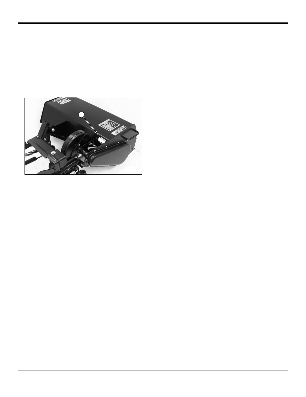
Record Identification Numbers
Mechanical Tiller
30-Inch Ser ial No. (010001 - )
If you need to contact an Authorized Service Center for
information on servicing, always provide the product model
and serial number.
You will need to locate the identification number for the
machine and for the engine. Record the information in the
spaces provided below.
A
M96308
DATE OF PURCHASE:
_________________________________________
DEALER NAME:
_________________________________________
DEALER PHONE:
_________________________________________
SERIAL NUMBER (A):
__ __ __ __ __ __ __ __ __ __ __ __ __ __ __ __ __
Product Identification
Page 4

TABLE OF CONTENTS
Tableof Contents
Safety ..........................................................................................1
PreparsVehicle ...................................................................................4
Installing . . . . . . . . . . . . . . . . . . . . . . . . . . . . . . . . . . . . . . . . . . . . . . . . . . . . . . . . . . . . . . . . . . . . . . . . . . . . . . . . . . . . . . . . .5
Removing........................................................................................9
Operating...................................................................................... 12
Service.........................................................................................17
Troubleshooting..................................................................................23
Storage.........................................................................................24
Assembly.......................................................................................25
Specifications....................................................................................29
Index...........................................................................................30
All information, illustrations and
specifications in this manual are based
on the latest information at the time of
publication. The right is reserved to
make changes at any time without
notice.
COPYRIGHT© 1999
Deere & Co.
John Deere Worldwide Commercial and
Consumer Equipment Division
Horicon, WI
All rights reserved
Previous Editions
COPYRIGHT©
Table of Contents
OMM141979 J9 - English
Page 5
SAFETY
Safety
Understanding The Machine Safety Labels
The machine safety labels shown in this section are placed
in impor tant areas on your machine to draw attention to
potential safety hazards.
On your machine safety labels, the words DANGER,
WARNING, and CAUTION are used with this safety-alert
symbol, (
hazards.
The operator’s manual also explains any potential safety
hazards whenever necessary in special safety messages
that are identified with the word, CAUTION, a nd the safetyalert symbol, (
c). DANGER identifies the most serious
c).
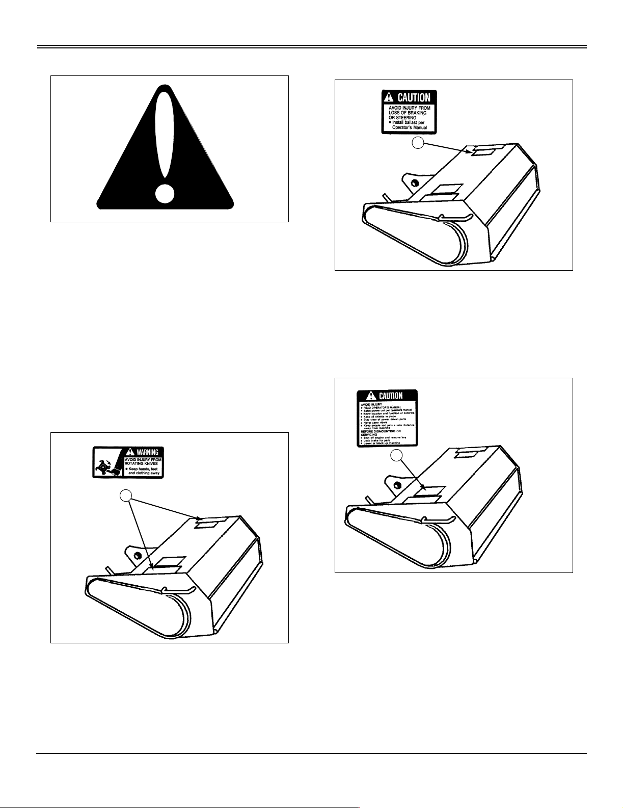
CAUTION (B)
M74626
AVOID INJURY FROM LOSS OF BRAKING OR
STEERING
• Install ballast per Operator’sManual.
B
M74608
CAUTION (C)
M74568
WARNING (A)
M74570
A
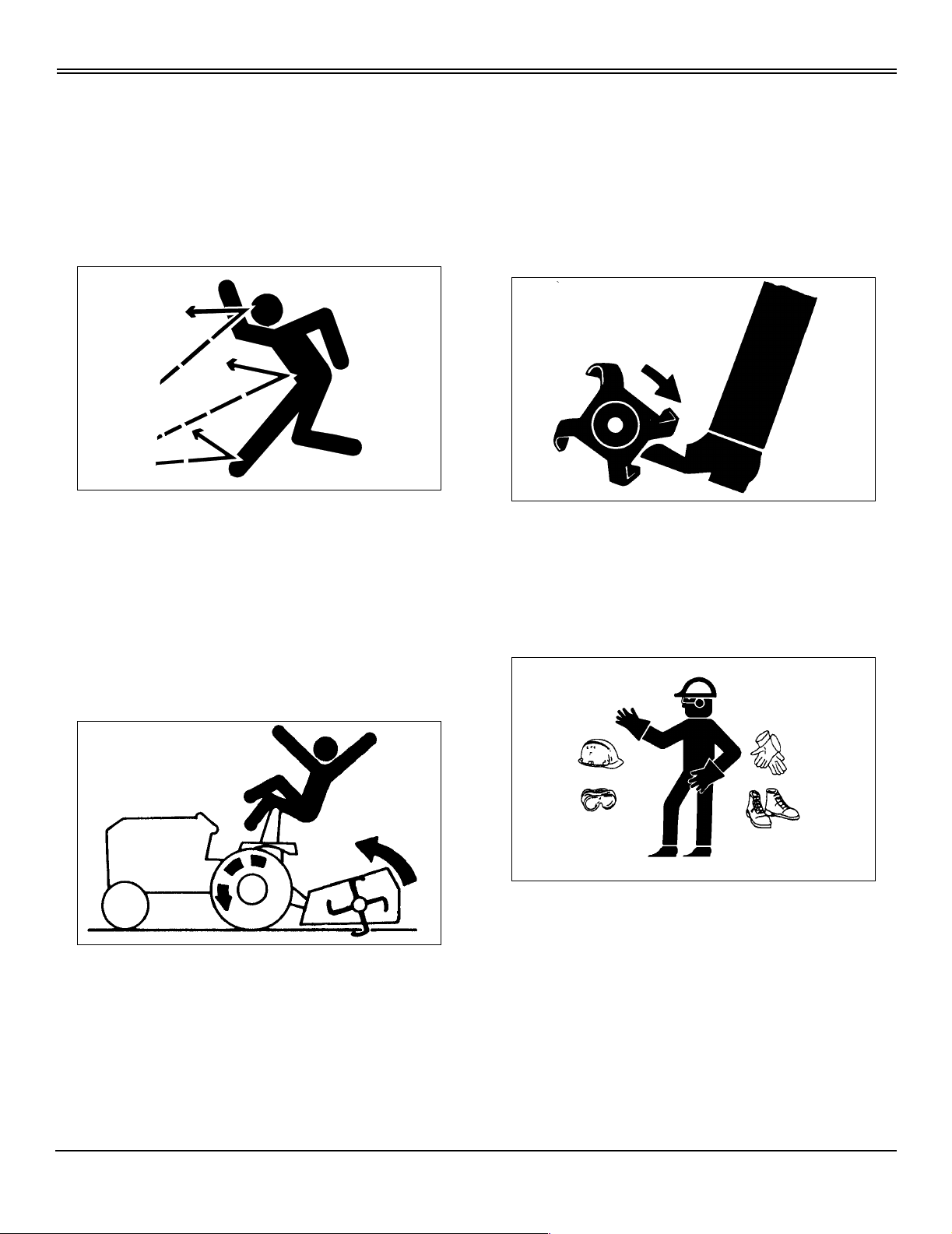
AVOID INJURY FROM ROTATING KNIVES
• Keep hands, feet and clothing away.
M74608
C
M74608
AVOID INJURY
• READ OPERATOR’SMANUAL
• Ballast power unit per operator’smanual.
• Know location and function of controls.
• Keep all shields in place.
• Stay clear of power driven parts.
• Never carry riders.
• Keep people and pets a safe distance away from
machine.
Safety - 1
Page 6
SAFETY
BEFORE DISMOUNTING OR SERVICING
• Shut off engine and remove key.
• Lock brake for park.
• Lowerorblockupmachine.
Operate Safely
• Checkvehicle brake actionbefore you operate.Adjust or
service brakes as necessary.
• Inspect machine before you operate. Be sure hardware
is tight. Repair or replace damaged, badly worn, or missing
parts. Be sure guards and shields are in good condition
and fastened properly. Make any necessary adjustments
before you operate.
• DO NOT let children or an untrained person operate
machine.
• Raise tiller as-high-as it will go before you drive between
work areas.
• DO NOT use tiller near the edge of a ditch or bank. Tiller
can push tractor.
• Slow down on slopes.
• Stop tiller when you are NOT tilling.
• Tines turn at 250 rpm and can cause serious injury.
Keep hands, feet and clothing away from tiller when tines
are turning—always keep bystanders well away.
Wear Appropriate Clothing
• Clear work area of objects that might be thrown. Keep
people and pets out of the work a rea. Stop machine if
anyone enters the area.
• If you hit an object, stop the machine and inspect it.
Make repairs before continuing operate. Keep machine
properly maintained and in good working order. Keep all
shields and guards in place and fastened properly.
• DO NOT leave machine unattended when it is running.
• Only operate during daylight or with good artificial light.
• DO NOT let anyone, ESPECIALLY CHILDREN, ride on
machine or vehicle.
• Wear close fitting clothing and safety equipment
appropriate for the job.
• Wearasuitableprotectivedevicesuchasearplugs.
Loud noise can cause impairment or loss of hearing,
• DO NOT wear radio or music headphones. Safe service
and operation requires your full attention.
Safety - 2
Page 7
SAFETY
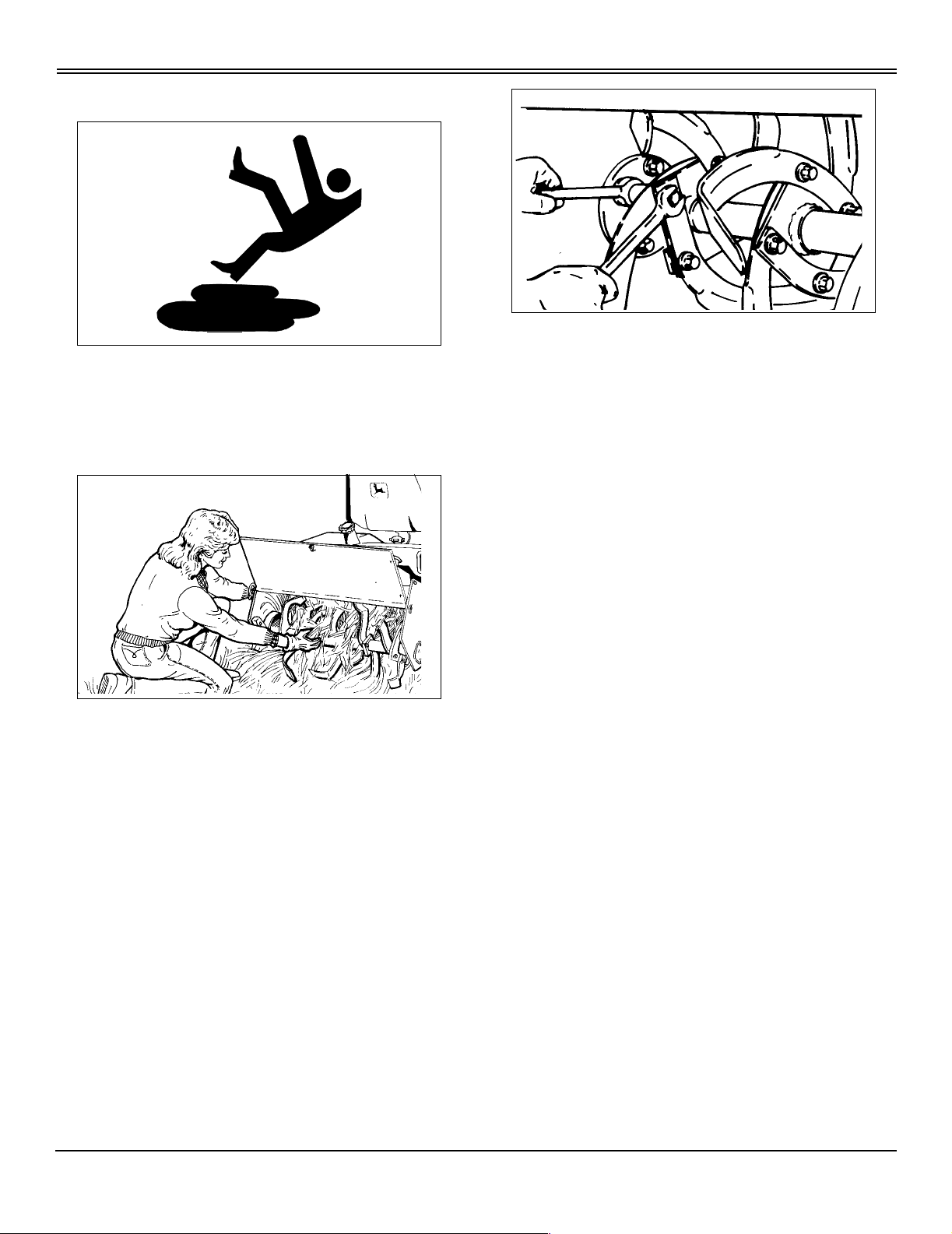
Practice Safe Maintenance
• Understand service procedure before doing work. Keep
area clean and dry.
• Never lubricate, service, or adjust machine while it is
moving. Keep safety devices in place and in working
condition. Keep hardware tight.
• Keep all parts in good condition and proper ly installed.
Fix damage immediately. Replace worn or broken parts.
Remove any buildup of grease or debris.
• Do not modify machine. Unauthorized modifications to
the machine may impair its function and safety.
• Keep hands, feet, clothing, jewelry, and long hair away
from any moving parts, to prevent them from getting
caught.
• Lower attachments to the ground before servicing
machine. Disengage all power and stop the engine. Lock
park brake and remove the key. Let engine cool.
• Securly support any machine elements that must be
raised for service work.
• Never run engine unless park brake is locked.
Safety - 3
Page 8

PREPARE VEHICLE
PrepareVehicle
Remove Mower Deck
Tractormower deck must be removed from before installing
tiller. See your tractor operator’s manual or mower deck
manual for removal instructions.
Ballasting Requirements
All tractors require front wheel weights to be installed when
using this tiller.
Follow these recommendations to help improve traction:
• Install tire chains on turf tires or install bar tires on the
tractor.
• Install rear wheel weights.
Ballast weights can be purchased from your Authorized
Service Center. See your tractor operator’s manual for
further information.
Prepare Vehicle - 4
Page 9
INSTALLING
Installing
Park Vehicle Safely
• Stop vehicle on a level surface, not on a slope.
• Disengage PTO.
• Engage the park brake.
• STOP the engine.
• Remove the key.
• Beforeyou leavethe operator’s seat, wait for engine and
all moving parts to STOP.
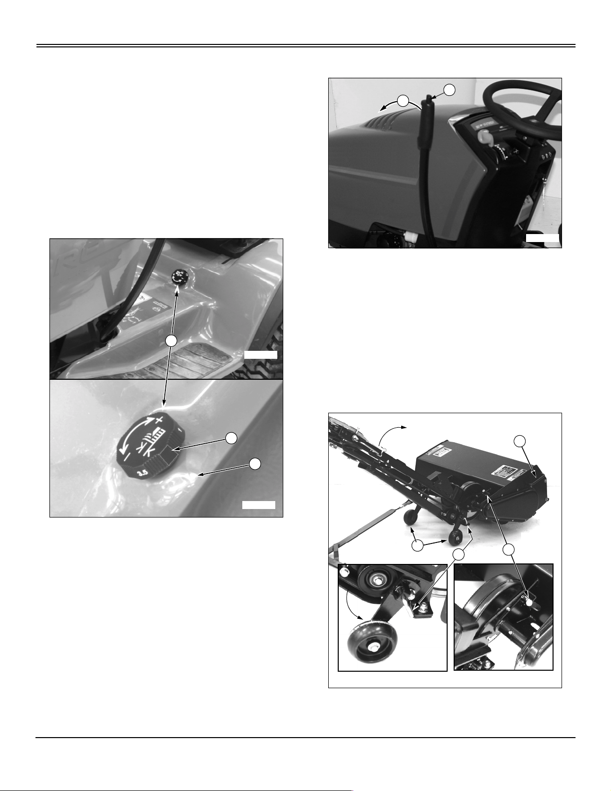
Setting Depth Control Knob
A
M96267
Move Implement Lift Lever
B
A
M97160
1. Pull implement lift lever (A) rearward slightly, then
depress and hold down button (B) to unlock lift leverlocking
mechanism.
2. Push lift lever (A) forward out of “RAISE” position,
releasebutton(B)asyoucontinuetopushliftleverall-theway forward until a loud metallic-click is heard, signalling
leveris in “LOCK-OUT” position, then release lift lever—it is
now locked into “LOWER” position.
B
C
M96268
Turn depth control knob (A) to “ZERO” setting (B), raised
indicator that is blank should be aligned with fender deck
raised indicator (C).
Put Tiller Frame Rails In Transport Position
B
C
D
M96275
M96259
A
M96274
1. Pull left frame rail up until locking pin (A) can be locked
into locking bracket hole. Push down on tiller housing
Installing - 5
Page 10
INSTALLING
handle (B) to rotate tiller housing while pulling left frame rail
upwards to gain clearance to lower frame wheels (C).
2. Unlock locking pin (D) and rotate frame wheel down into
engaged position and make sure locking pin locks into
locking hole. Lock right frame wheel down into engaged
position in similar fashion.
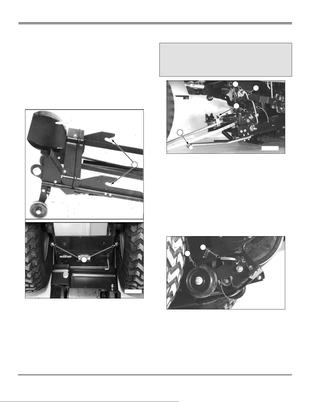
Install Tiller On Tractor Rear-Frame Mounting Hardware
1. Roll tiller under rear of tractor.
A
Engage Frame Support Rod
cCAUTION:Avoid injury! Maintain a secure grasp
of lift handle until support rod is in place. Keep
hands clear of pinch areas between tiller and
tractor frame.
D
A
B
1. Move to left side, under tractor footrest—open tiller latch
clips (A) at both sides of tiller.
2. Push and hold down lift handle (B).
C
M96279
M41781
B
M96255
2. Get a helper or use a floor jack with wheels to safely lift
and install tiller, frame hooks (A) slide over spacers (B) of
rear-frame mounting hardware.
3. Pivot left-side frame support rod (C) upward so loop in
rod is under mounting pin (D) of tractor frame.
4. Slowly release downward pressure on lift handle (B) to
engage rod loop.
Lock Frame Wheels into Storage Position
A
B
M96277
1. Move to left rear, behind tractor drive wheels—pull and
hold out wheel locking pin (A).
2. Swing left wheel assembly (B) up into “RAISED”
position. Make sure locking pin engages hole in locking
bracket. Repeat steps for right frame wheel.
Installing - 6
Page 11
Disengage Frame Support Rod
cCAUTION: Avoid injury!
Maintain a secure grasp of lift handle (B) until
tiller frame clips (A) are seated against
mounting pins (D).
Keep hands clear of pinch areas between tiller
and tractor frame.
D
INSTALLING
IMPORTANT: Avoid damage! Check that belt
tensioning idler spring (G) is installed in top detent
of belt tensioning lever (D). Damage to spring may
occur or tensioning of idler may not apply proper
tension on drive belt if spring is installed in the
lower detent.
E
C
F
B
A
M96279
1. Move to left side, under tractor footrest—hold lift handle
(B) down.
2. Pivot support rod (C) d own into storage position.
3. Slowly release downward pressure on lift handle (B)
until cups of tiller frame latches (A) are seated up against
mounting pins (D).
Fasten Frame Clip Latches And Install Belt
C
A
B
G
D
M96283
3. Move to right side, under tractor footrest—swing belt
tensioning lever (D) toward front of tractor to loosen belt
tensioning idler (E).
4. Move belt tensioning idler (E), by hand, towards right
frame to help install belt on PTO drive sheave (F). Release
idler after belt is completely seated in sheave.
5. Swing belt tensioning lever (D) toward rear of tractor to
tighten belt.
Fasten Tiller Lift Rod to Tractor Lift Link
NOTE: Lock implement lift lever into “LOWER”
position and unlock tiller housing from “TRANSPORT”
position and lower it onto ground before fastening tiller
lift rod (B)—this allows ease-of-alignment between
tractor lift link (A) and tiller lift rod pin (C).
A
D
M96280
1. Close clip of latch (A) around mounting pin (B) on each
side of tractor.
2. Install spring locking pin (C), from bag of parts, into
holes of each clip latch (A), outside-in, to preventclips from
vibrating or bouncing open.
Installing - 7
D
C
B
M96281
1. Move to right side, under tractor footrest—as you rotate
Page 12

INSTALLING
tiller lift rod (B) upright, align tractor lift link (A) so pin (C) fits
into hole (D) of lift link (A).
C
E
F
M96284
2. Install M13 x 24 x 2.5 mm washer (E), from bag of parts,
on lift rod pin (C).
3. Fasten lift rod to lift link with spring locking ring (F), from
bag of parts.
Adjust Tiller Lift Height
B
A
E
D
F
G
C
M96294
3. Move to left side of tiller housing—grasphandle(C)to
raise tiller housing to remove pressure on transport locking
pin (D) and continue to hold tiller housing stationary while
you pull transport locking pin (D) out and rotate it forward
into “LOCK-OUT” position,rolledpin(E)lockedinframe
slot (F).
4. Slowly lower tiller housing down (G) against tractor lift
linkage.
M97160
1. Push implement lift lever (A) forward slightly, then
depress and hold down button (B) to unlock lift leverlocking
mechanism.
2. Pull lift lever (A) reward out of “LOWER” position,
release button (B) and continue to pull lever all-the-way
reward until a loud metallic-click is heard, signalling lever is
in “LOCK-OUT” position, then release lift lever—it is now
locked into “RAISE” position.
C
M96289
5. Measure distance (C) between lowest tine and ground.
Distance should be 75 mm (3-in.). This will allow a
maximum 150 mm (6-in.) tilling depth and enough ground
clearance for turns on ends of tilling area. If distance is not
correct, see Adjusting Tilling Depth in the OPERATING
section.
Installing - 8
Page 13

REMOVING
Removing
Park Vehicle Safely
• Stop vehicle on a level surface, not on a slope.
• Disengage PTO.
• Engage the park brake.
• STOP the engine.
• Remove the key.
• Beforeyou leavethe operator’s seat, wait for engine and
all moving parts to STOP.
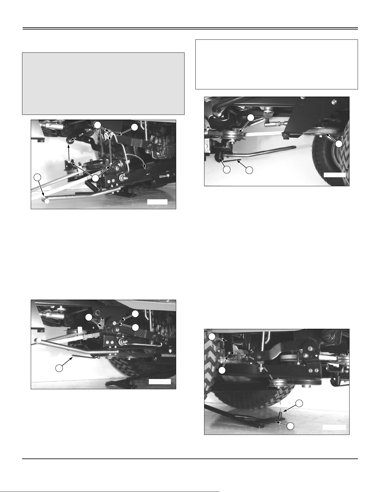
Move Implement Lift Lever
B
A
Disconnect Tiller Lift Rod From Tractor Lift Link And Unhook Right Clip Latch
NOTE: Lock implement lift lever into “LOWER”
position and unlock tiller housing from “TRANSPORT”
position and lower it onto ground before disconnecting
tiller lift rod (B)—this allows ease-of-disconnect
between tractor lift link (A) and tiller lift rod pin (C).
A
C
1. Move to right side, under tractor foot rest—remove
spring locking ring (D) and washer (E) from tiller lift rod pin
(C).
E
D
B
M96284
M97160
1. Pull implement lift lever (A) rearward slightly, then
depress and hold down button (B) to unlock lift leverlocking
mechanism.
2. Push lift lever (A) forward out of “RAISE” position,
release button (B) as you continue to push lift lever all-theway forward until a loud metallic-click is heard, signalling
leveris in “LOCK-OUT” position, then release lift lever—itis
now locked into “LOWER” position.
A
G
C
B
F
M96281
2. Pull tiller lift rod pin (C) from lift link (A) as you lower tiller
lift rod (B) inward, onto ground.
3. Store washer (E) and spring locking ring (D) on lift rod
pin (C).
4. Removespring locking pin from clip latch (F) and flip clip
of latch rearward to clear tractor mounting pin (G).
Removing - 9
Page 14

REMOVING
Disengage Belt And Unhook Left Clip Latch
B
A
M96283
1. Move to right side, under tractor footrest—move belt
tensioning idler lever (A) out of “ENGAGED” position into
“DISENGAGED” position (pointing toward front of tractor).
2. Pull and hold tensioning idler (B) towards right frame
while you remove belt from P TO drive sheave (C).
E
C
stationary while you rotate transport locking pin handle (H)
rearward until spring tension “LOCKS-OUT” pin into
“TRANSPORT” position.
5. Slowlylift housing handle (E) up-and-down to ensure pin
is “LOCKED-OUT” before letting go of handle.
Engage Frame Support Rod
cCAUTION:Avoid injury! Maintain a secure grasp
of lift handle until support rod is in place. Keep
hands clear of pinch areas between tiller and
tractor frame.
C
B
D
M96280
3. Move to left side, under tractor footrest—remove spring
locking pin from clip latch (D) and flip latch of clip reward to
clear tractor mounting pin (E). I nstall spring locking pins in
clips for storage when finished removing tiller from tractor.
G
H
H
F
E
A
M96279
1. Move to left side, under tractor footrest—push and hold
down lift handle (A) as you pivot left-side frame support rod
(B) upward so loop in rod is under mounting pin (C) of
tractor frame.
2. Slowly release downward pressure on lift handle (A) to
engage rod loop.
M96294
4. Move to left side of tiller housing—grasp handle (E) to
raise tiller housing to align transport locking pin (F) with
locking plate hole (G). Continue to hold tiller housing
Removing - 10
Page 15

REMOVING
Lock Frame Wheels Into Engage Position
A
A
M96277
1. Move to left rear, behind tractor drive wheels—pull and
hold out wheel locking pin (A).
2. Swing left wheel assembly (B) down into “ENGAGE”
position. Make sure locking pin engages hole in locking
bracket. Repeat for right frame wheel.
Remove Tiller From Tractor Rear-Frame Mounting Hardware
A
M41781
1. Get a helper or use a floor jack with wheels to safely
support and slide tiller housing as you slide frame hooks
(A) from of rear-frame mounting hardware (B).
B
Disengage Frame Support Rod
cCAUTION: Avoid injury! Maintain a secure grasp
of lift handle (A). Keep hands clear of pinch
areas between tiller and tractor frame.
B
A
M96279
1. Move to left side, under tractor footrest—push and hold
lift handle (A) down.
2. Pivot support rod (B) down into storage position.
3. Slowly release downward pressure on lift handle (A).
M96255
2. Carefully roll tiller out-from-under rear of tractor.
Removing - 11
Page 16

OPERATING
Operating
Tilling Tips
Install correct front and rear tractor weights. See I nstall
Weights and Chains in Installing the Tiller section.
IMPORTANT: Avoid damage!
DONOTbackupormakesharpturnswiththetiller
in the ground.
Till with engine at FAST throttle, control ground speed with
appropriate transmission speed range.
Check tines before you till. Replace missing, bent, or
broken tines.
When you till hard ground or sod, till at a shallow depth for
the first pass. Till deeper on each pass after that.
When you till a small area, make a pass through the
middle, then circle alongside the original pass, working to
the outside. After you finish, make a few passes around the
edge to cover ridges left by turning.
Till straight ahead when possible. This will leave fewer
ridges from turning.
For seed bed preparation, till the soil once in the fall.
Decaying vegetation will add valuable nutrients to the soil
by spring. If the terrain is hilly or uneven, wait until spring,
or leave some untilled strips, to help reduce soil erosion.
The climate and terrain will help you decide the best time to
till.
Before Tilling
Always pick up rocks, branches, and other objects that
might damage tiller.
Always check tines before tilling. Repair or replace loose,
bent, or broken tines.
Move Implement to “LOWER” Position
B
A
M97160
1. First pull implement lift lever (A) rearward slightly, t hen
depress and hold down button (B) to unlock lift leverlocking
mechanism.
2. Push lift lever (A) forward out of “RAISE” position
(shown), release button (B) as you continue to push lift
lever all-the-way forward until a loud metallic-click is heard,
signalling lever is in “LOCK-OUT” position, then release lift
lever—it is now locked into “LOWER” position (see next
figure).
“LOCK-OUT” Position: locks tiller in “LOWER” position—for
difficult conditions, such as, heavy soils, clay,or sod. When
lift lever is “LOCKED-OUT” this means the lift spring in the
lift linkage has no effect on tiller weight.
M34147
Test soil condition by squeezing it in your hand. If soil forms
a ball, it is too wet to till. If soil does not compress easily or
falls apart, it is ready to till.
DO NOT till when soil is wet. Wet soil will stick to tines and
tine shaft. Wet soil will clump-up and dry out hard, making it
difficult to work during t he growing season.
Before tilling mow tall weeds and grass to keep them from
wrapping around tines or tine shaft.
Operating - 12
Page 17

OPERATING
Move Implement to “RAISE” Position
B
A
M97160
1. First push implement lift lever (A) forward slightly,then
depress and hold down button (B) to unlock lift leverlocking
mechanism.
2. Pull lift lever reward out of “LOWER” position, release
button (B) and continue to pull lever all-the-way reward until
a loud metallic-click is heard, signalling lever is in “LOCKOUT” position, then release lift lever—it is now locked into
“RAISE” position.
“LOCK-OUT” Position: locks tiller in “RAISE” position—for
making turns at end of rows. When lift lever is “LOCKEDOUT” this means the lift spring in the lift link age has no
effect on tiller weight.
“FLOAT”Position allows implement to move with contour of
ground which causes the lift spring in the lift linkage to exert
maximum depth force on tiller weight. “FLOAT” position
performs best in light-to-medium soils: such as sandy,
loam, or soils previously tilled.
Using Depth Control Knob
Adjust depth control knob to set tilling depth. Tiller will
return to the same depth each time you lower it.
B
A
M96267
1. Use lift lever (B) to raise tiller as high as it will go.
2. Turn knob (A) clockwise to raise the tiller depth or
counter-clockwise to lower the depth, as viewed from
operator’sseat.
3. If you cannot adjust for the desired tilling depth, see
Adjusting Tilling Depth.
Move Implement to “FLOAT” Position
B
A
M97160
1. First pull implement lift lever (A) rearward slightly, then
depress and hold down button (B) to unlock lift leverlocking
mechanism.
2. Push lift lever(A) out of “RAISE” position, release button
(B) and lift lever. Lift lever is now in “FLOAT” position
(between “RAISE” and “LOWER” positions).
Adjusting Tilling Depth
1. Stop engine and set PARK brake.
A
M97160
2. “LOCK-OUT” lift lever (A) into “LOWER” position to
release spring tension in lift linkage.
Operating - 13
Page 18

OPERATING
E
C
B
A
D
M96284
3. Move to right side, below tractor footrest—remove
spring locking ring (A) and flat washer (B) form lift rod pin
(C).
4. Remove lift rod (D) form tractor lift link (E).
IMPORTANT: Avoid damage!
DO NOT expose more than 30 mm (1-1/4 in.) of
thread (G) or lift rod and clevis threads could be
damaged or lift rod could separate from clevis.
NOTE: Maximum tilling depth is 150 mm (6-in.)—
bottom of shaft to bottom edge of lowest tine.
H
M96289
• Measure distance (H) between ground and the
lowest tine. The distance should be 75 mm (3-in.).
Operating Tiller
cCAUTION: Avoid injury!
• Pick up objects from tilling area.
• Guards and shields must be in place.
• Clear the work area of people.
• DO NOT let children operate the tractor/tiller.
• DO NOT let children ride on the tractor or
tiller.
D
G
F
M96272
Picture Note: Tiller frame removed from tractor for
clarity.
5. Turn lift rod (D) clockwise into clevis (F) to increase
tilling depth and counterclockwise out of clevis (F) to
decrease tilling depth.
6. Fasten lift rod (D) to tractor lift link (E) with washer (B)
and spring locking ring (A).
7. Check tiller ground clearance:
• Use lift lever to raise tiller as high as it will go.
B
A
M96277
1. Move to rear of tractor—lock frame wheels (A) in the
RAISED position (shown). Make sure locking pins (B) are
locked into locking bracket hole.
Operating - 14
Page 19

OPERATING
E
D
F
G
2. Move to left side of tiller housing—grasp handle (C) to
raise tiller housing to remove pressure on transport locking
pin (D) and continue to hold tiller housing stationary while
you pull transport locking pin (D) out and rotate it forward
into “LOCK-OUT” position,rolledpin(E)lockedinframe
slot (F).
3. Slowly lower tiller housing down (G) against tractor lift
linkage.
4. Start engine. Put throttle lever at 1/4 position. (See your
tractor operator’s manual for throttle lever operation.)
NOTE: For those tractors with Reverse Implement
Option (RIO), the tiller will stop when the tractor is put
in reverse unless Reverse Implement Switch (RIS) is
activated before going in reverse.
5. To engage tiller, put PTO control in the ON position.
(See your tractor operator's manual for PTO operation.)
6. Push throttle lever to the FAST position.
7. UNLOCK the park brake.
8. Till ground at a safe travel speed using appropriate
transmission ground speed.
C
M96294
A
M96293
7. Move to rear of tiller—lift shield (A) to gain access to
tines and shaft.
8. Safely inspect or unplug tines and shaft area.
Parking Tiller
1. STOP tractor and turn PTO switch OFF.
2. STOP engine, LOCK park brake, and remove key.
3. Lower tiller to ground.
Transporting Tiller
Drive the tractor with the tiller in the “TRANSPORT”
position when traveling from one tilling area to the other.
Drive the tractor at a safe travel speed. Slow down on
slopes or rough ground.
Place tiller in “TRANSPORT” position as follows:
Inspecting Or Unplugging Tiller
cCAUTION: Avoid injury! Stop the engine and
wait for all moving parts to stop before leaving
tractor seat.
1. STOP the tractor.
2. Put PTO control in the OFF position.
3. Lower tiller to the ground.
4. LOCK the park brake.
5. STOP the engine.
6. Remove the key.
B
A
M97160
1. First push implement lift lever (A) forward slightly, then
depress and hold down button (B) to unlock lift leverlocking
Operating - 15
Page 20

OPERATING
mechanism.
2. Pull lift lever (A) reward out of “LOWER” position
(shown),releasebutton(B)andcontinuetopullleverallthe-way reward until a loud metallic-click is heard,
signalling lever is in “LOCK-OUT” position, then release lift
lever—it is now locked into “RAISE” position, lift lever in
close proximity to steering wheel.
F
D
E
C
G
M96294
3. Move to left side of tiller housing—grasp handle (C) to
raise tiller housing to align transport locking pin (D) and
transport bracket locking hole (E). Rotate transport locking
pin (D) reward to unlock rolled pin (F) from frame slot (G)
and release transpor t locking pin so it springs into “LOCKOUT” position in transport bracket locking hole (E).
4. Slowly lift up and push down on handle (C) before
releasing it to ensure tiller housing is “LOCKED-OUT” into
“TRANSPORT” position.
Operating - 16
Page 21

Service
Service Intervals
5 Hours Check belt tension.
SERVICE
Clean under belt shield.
10 Hours Lubricate drive sheave bearing.
Lubricate rear jackshaft.
Checking Belt Tension
A
Picture Note: Tiller removed for clarity purposes
only.
M96301
G
F
M96300
• Moveto left rear of tiller frame—loosen nut (F) on the
idler pulley.
C
H
M41784
1. Check position of belt tension rod (A):
B
A
C
D
E
M72980
• If rod end is in position (B), against the vertical frame
rail (C), the belt is too tight and must be loosened.
• If rod end is in position (D), extends beyond
horizontal frame rail (E), the belt is too loose and must
be tightened.
2. To adjust belt tension:
• To tighten belt—turn bolt (G) counter-clockwise until
a 3 mm (1/8 in.) clearance existsbetween inside edge of
rod end (H) and vertical frame rail (C).
• To loosen belt—turn bolt (G) clockwise until a 3mm
(1/8 in.) clearance exists between inside edge of rod
end (H) and vertical frame rail (C).
• Tighten nut (F) on the idler pulley after adjustment.
Service - 17
Page 22

SERVICE
Cleaning Under Belt Shield
B
A
M96299
Picture Note: Tiller removed for clarity purposes
only.
1. Move to left side of tiller housing—remove two selftapping cap screws (A) and belt shield (B).
Lubricating Drive Sheave Bearing
B
A
M96309
Picture Note: Tiller removed for clarity purposes
only.
Move to front of tiller frame—lubricate drive shaft assembly
bearing (A) at grease fitting (B) with a Multi-Purpose
Grease, or equivalent, until grease comes out of bearing
seals.
M96305
2. Clean dirt from sheave and surrounding area.
3. Install shield (B) and self-tapping cap screws (A) until
snug—DO NOT over-tightenor youmay damage threads in
shield holes.
Lubricating Rear Jackshaft
A
M96310
Picture Note: Tiller removed for clarity purposes
only.
Move to left side of tiller housing—lubricate jackshaft
grease fitting (A) with two or three shots of a Multi-Purpose
Grease, or equivalent.
Remove Primary Drive Belt
1. Remove tiller from tractor. (See the REMOVING
section.)
Service - 18
Page 23

SERVICE
B
A
D
C
C
M96301
2. Loosen flange lock nut (A) on tensioning idler. Move belt
guide (B) away from belt.
3. Loosen top jam nuts (C), one on each side, to tilt guide
bolts (D) away from drive sheave.
4. Remove belt.
Install Primary Drive Belt
1. Install belt on drive sheave with wide-edge of belt facing
guide bolts (D).
2. Tighten top jam nuts (C), one on each side, to properly
align guide bolts (D).
3. Install belt between tensioning idler and belt guide (B)
so narrow-edge of belt faces belt guide (B).
B
E
A
C
D
M96300
2. Removetwoself-tappingcapscrews(A)toremovebelt
shield (B).
3. Loosen flange nut (C) to loosen tensioning idler (D).
4. Turn bolt (E) clockwise to move tensioning idler (D) up in
the slot.
G
A
B
M97633
4. Position belt guide (B), as shown. Tighten tensioning
idler flange lock nut (A) to 40 N•m (354 lb-in.) while holding
belt guide stationary.
Remove Secondary Drive Belt
1. Remove tiller from tractor. (See the REMOVING
section.)
F
M96306
5. Move to front of tiller frame—remove secondary belt
from front idler (F) and front drive sheave (G).
I
H
J
M41764
6. Move to left rear of tiller—remove lock nut (H) on inside
of frame from idler mounting bolt (I) to remove V-idler (J)
from inside of belt.
Service - 19
Page 24

K
SERVICE
J
E
K
M96305
7. Remove secondary belt (K) from tiller drive sheave.
Install Secondary Drive Belt
B
A
M41766
1. Install new secondary drive belt with one twist (A), as
shown, to seat “V” of belt in secondary drive sheave (B).
DO NOT cross-over belt (forming an “X” pattern) when
installing or tiller drive rotation will be reversed.
C
I
F
M96300
C
H
M41784
3. Turn bolt (E) counterclockwise to move tensioning idler
(F) as far down in slot as necessary to tension belt
properly—until inside-edge of front gauge rod (G) has
3 mm (1/8 in.) clearance from vertical frame rail (H).
4. Tighten tensioning idler nut (I).
D
B
M41764
2. Move to left rear of tiller—install V-idler (B) inside belt
and fasten with mounting bolt (C), outside-in, and tighten
withlocknut(D)oninsideofframe.
5. Install shield (J) and fasten with two self tapping cap
screws (K) until snug—DO NOT over-tighten or you may
damage threads in shield holes.
Replacing Tines
cCAUTION: Avoid injury! DO NOT work under a
raised tiller unless it is safely supported. Tiller
could fall on you, causing serious injury.
1. Park machine safely.
Service - 20
Page 25

SERVICE
2. Raise tiller as high as it will go if still on tractor.
NOTE: For ease in replacing tines, you can remove
tiller from the tractor and turn it completely upside
down. Put down protective tarp or carpet to protect
paint finish.
3. Put tiller in TRANSPORT position. (See Transporting
Tiller in OPERATING section.)
NOTE: Make sure you install the new tines and
hardware EXACTLY as the old tines and hardware were
positioned. Use the pictures to help you install tines
correctly. Properly installed tines have a step-up
pattern from left-to-right.
Each cluster of tines MUST have two left tines (D) and
two right tines (E):
• Alternate left and right tines in each cluster.
• AboltwithNOSPACERisanM10x35bolt.
• A bolt with ONE SPACER is an M10 x 45 bolt.
• AboltwithTWOSPACERSisanM10x60bolt.
M96313
4. Safelyput jack stand or blocks under tiller (tiller removed
or still on tractor).
M96311
5. Replace tines:
D
B
C
E
A
M96317
• Left Set: Remove lock nuts (A), bolts (B), spacers
(C), two left tines (D), and two right tines (E). Remember
to install new bolts so heads are to left side and new
lock nuts are to right side. A total of two spacers are
used in this set.
Service - 21
Page 26

SERVICE
D
E
C
B
A
M96318
• MiddleTine Sets: Remove lock nuts (A), bolts (B),
spacers (C), two left tines (D), and two right tines (E).
Remember to install new bolts so heads are to left side
and new lock nuts are to r ight side. A total of eight
spacers are used in these middle tine sets—four in each
set.
Replacing Shaft Bolts
B
A
M96317
1. Moveto left side of tiller shaft—removelock nuts (A) and
bolts (B).
2. Align shaft holes and install new bolts (B) and lock nuts
(A). Tighten lock nuts to 75 N•m (55 lb-ft).
Grease
Use a SAE Multi-purpose grease based on the expected air
temperature range during the service interval.
D
B
A
C
E
M96304
• Right Tine Set: Remove lock nuts (A), bolts (B),
spacer (C), two left tines (D), and two right tines (E).
Remember to install new bolts so heads are to right side
and new lock nuts are to left side. A total of two spacers
areusedinthisset.
6. Tighten all lock nuts to 75 N•m(55lb-ft).
Service - 22
Page 27

TROUBLESHOOTING
Troubleshooting
Using Troubleshooting Chart
If you are experiencing a problem that is not listed in this
chart, see your authorized dealer for service.
Whenyouhavecheckedallthepossiblecauseslistedand
you are still experiencing the problem, see your authorized
dealer.
IF CHECK
Tiller is Noisy Tines need to be straightened, tightened or replaced.
Rocks and debris in tilling area.
Erratic Tiller Operation Tines need to be straightened, tightened or replaced.
Drive belts need to be tightened or replaced.
Tiller Will Not Till Drive belt needs to be tightened or replaced.
Replace shaft bolts.
Tractor and Engine Slow Down Throttle not at “FAST” position.
Tilling too deep
Decrease travelspeed.
Not Enough Tillage Depth Throttle not at “FAST” position.
Check tine placement or replace tines.
Tine Shaft Rotates But Tiller Does Not Till Clean tines.
Install tines correctly.
Till at shallower depth.
Replace shaft bolts.
Tilled Ground is Uneven Rocks and debris in tilling area.
Keep travel speed the same.
Tilling Results Are Poor Cut tall grass or weeds before you till.
Adjust transmission travel speed - slow down.
Tractor Will Not Pull Tiller Because Wheels Slip
Too Much
Tine Shaft Does Not Rotate Remove rock or trash wedged between shaft and housing.
Cut tall grass or weeds before you till.
Till at shallower depth.
Make more than one pass.
Add rear wheel weights or tire chains on turf tires, or install bar tires.
Replace shaft bolts.
Tighten or replace drive belts.
Tiller Hard To Raise Remove dirt, mud, and trash from shaft and tines.
Tiller Bounces When It Is Tilling Or Will Not
Penetrate
Tiller Pushes Tractor Add rear wheel weights, or tire chains on turf tires, or install bar tires.
Secondary drive belt installed incorrectly.
Troubleshooting - 23
Page 28

STORAGE
Storage
Storing Tiller
1. Remove tiller from tractor. (See the REMOVING
section.)
2. Clean tiller with water pressure.
3. Check belts. If necessary, get new belts from your
Authorized Service Center. DO NOT install the new belts
until you take tiller out of storage.
4. Replace or repair badly worn or damaged parts.
5. Paint scratched areas to preventrust.
6. Lubricate two grease points. (See the SERVICE
section.)
7. Store tiller on a hard, level surface in a clean, dry place.
If you must store tiller outside, cover it with a waterproof
cover.
Storage - 24
Page 29

ASSEMBLY
Assembly
Identify Parts – 30 Inch Mechanical Tiller
M96256
Bag of Parts
B
A
F
J
N
C
G
K
O
Qty. Used Part Description Size
1 Handle, Lift (A)
2 Pin, Mounting (B)
1 Sheave, Idler (C)
1 Guide, Belt (D)
2 Bolt, Flange (E) M12 x 1.75 x 50 mm
2 Bolt, Flange (F) M6 x 1.00 x 30 mm
4 Bolt, Hex (G) M8 x 1.25 x 25 mm
1 Bolt, Flange (H) M8 x 1.25 x 50 mm
2 Spacer, Rear (I)
2 Nut,Flange(J) M6x1.00mm
5 Locknut, Flange (K) M8 x 1 .25 mm
1 Washer, Flat (L) M13 x 24 x 2.5 mm
2 Locknut, Flange (M) M12 x 1.75 mm
1 Tiller Clip, Left-Hand (N)
1 Tiller Clip, Right-Hand (O)
2 Pin, Spring Locking (P)
1 Ring, Spring Locking (Q)
D
H
E
I
L
P
M
Q
M96254
Assembly - 25
Page 30

Install Tractor Rear-Frame Hardware
ASSEMBLY
C
C
A
M96276
B
M96287
1. Frombag of parts, install one spacer (A) on each M12 x
1.75 x 50 mm flange bolt (B).
2. Install spacers and bolts in BOTTOM holes at rear of
tractor frame and secure with M12 x 1.75 locknuts (C) on
inside of tractor frame. Tighten locknuts to 105 N•m (78 ftlb).
C
B
F
E
A
M96278
2. Place draft ar ms (A) back in their or iginal positions.
Make sure spacers (E) are installed properly inside draft
arms (A).
3. Install original washers (C) on tiller mounting pins (F),
from bag of parts, then install in draft arms, spacers, and
mounting brackets. Fasten with original locknuts (B) on
inside of mounting brackets. Tighten locknuts to 140 N•m
(103 lb-ft).
Install Clips On Tiller Frame Rails
D
Install Tractor Mid-Frame Mounting Pins
IMPORTANT: Avoid damage! If spacer (E) falls out of
draft arm (A) when pivot bolt (D) is removed, return
spacer to its original position inside the draft arm
hole. Damage may occur if spacer is missing or
improperly installed.
C
D
B
E
1. Locate draft arms (A) under left and right tractor foot
rests.Removelocknut(B),washer(C),andpivotbolt(D)
from each side. Discard original pivot bolts.
A
M96288
D
A
C
A
M96260
B
From bag of parts, install left and right tiller clips (A) to
outside of correct tiller frame rails, so latches (D) flip
forward. Fasten with two M8 x 1.25 x 25 mm hex bolts (B)
and M8 x 1.25 locknuts (C). Tighten locknuts to 28 N•m
(247 lb-in.).
Assembly - 26
Page 31

ASSEMBLY
Put Tiller Frame Rails In Transport Position
B
M96259
C
M96275
A
M96274
B
F
D
A
E
C
M97633
2. From bag of parts, position idler sheave (A) and belt
guide (B) onto tiller tensioning arm (C). Make sure shoulder
(D) on sheave is seated against the belt guide.
3. Install M8 x 1.25 x 50 mm flange bolt (E) from bottom
side of tensioning arm. Install M8 x 1.25 locknuton top side
of sheave finger tight only.
1. Pull left frame rail up until locking pin (A) can be locked
into locking bracket hole. Push down on tiller handle (B) to
rotate tiller housing while pulling left frame rail up to gain
clearance to lower left frame wheel.
2. Unlock locking pin (C) and rotate wheel down into
engaged position and make sure locking pin locks in
locking hole. Lock right frame wheel down into engaged
position in similar fashion.
Install Lift Handle And Idler Sheave
B
A
M96261
C
F
A
M96262
B
4. Remove shipping tape from belt and route belt between
belt guide (B) and idler sheave (A) so small V-edge (F) is
facing belt guide.
G
B
M97633
1. From bag of parts, install lift handle (A) under left frame
rail with two M6 x 1.0 x 30 mm flange bolts (B), top-down,
and fasten with two M6 x 1.0 flange nuts (C). Tighten two
flange nuts to 17 N•m (150 lb-in.).
Assembly - 27
5. Adjust the position of belt guide (B) as shown. Make
sure belt guide does not contact idler sheave at (G).
Page 32

ASSEMBLY
NOTE: Make sure belt guide does not move out of
position when tightening locknut.
6. TightenM8x1.25locknutto40N•m (354 lb-in.).
7. After tightening, make sure the idler sheave rotates
freely on the tensioning arm.
8. Pull the belt tight and make sure belt guide does not
contact idler sheave or belt.
Adjust Tiller Lift Rod
C
B
A
M96256
C
B
A
M96272
Turn threaded end (B) of tiller lift rod (A) clockwise into
clevis (C), far enough so three-to-four threads are exposed
inside clevis.
Assembly - 28
Page 33

SPECIFICATIONS
Specifications
Tiller Specifications
Tiller Specifications
Dimensions:
CuttingWidth.......................................................................762mm (30-in.)
MaximumCuttingDepth...............................................................150mm (6-in.)
MaximumLiftHeight...................................................................76mm(3-in.)
TransportHeight .....................................................................204mm(8-in.)
RotorDiameter......................................................................356mm(14-in.)
Miscellaneous:
RotorSpeed.............................................................................. 250rpm
DriveChain......................................................................No.50RollerChain
TineShaftBearings..............................................................SealedBallBearings
Recommended Lubricants
Grease....................................................................SAEMulti-PurposeGrease
(Specifications and design subject to change without notice.)
Specifications - 29
Page 34

INDEX
Index
B
Ballasting Requirements .........................................4
Before Tilling ........................................................12
Belt Shield, Cleaning Under .................................18
Belt Tension, Checking .........................................17
Belt, Disengage .....................................................10
Belt, Install ..............................................................7
C
Clips, Tiller Frame Rails - Install .........................26
D
Depth Control Knob, Setting ..................................5
Depth Control Knob, Using ..................................13
Drive Sheave Bearing, Lubricating .......................18
F
Frame Clip Latches, Fasten ....................................7
Frame Support Rod, Disengage ........................7, 11
Frame Support Rod, Engage .............................6, 10
Frame Wheels, Engage Position ...........................11
Frame Wheels, Storage Position .............................6
G
Grease ...................................................................22
H
Hooks on Spacers, Install ........................................6
I
Idler Sheave, Install ..............................................27
Implement Lift Lever, Move ...............................5, 9
Implement to "FLOAT" Position, Move ..............13
Implement to "LOWER" Position, Move .............12
Implement to "RAISE" Position, Move ................13
L
Left Clip Latch, Unhook .......................................10
Lift Handle, Install ................................................27
Lift Height, Adjust Tiller ........................................8
Lift Rod, Install .....................................................28
Lubricants, Recommended ...................................29
Lubricating Drive Sheave Bearing ........................18
Lubricating Rear Jackshaft ...................................18
M
P
Parking Tiller ........................................................15
Parts, Identify ........................................................25
Primary Drive Belt, Install ....................................19
Primary Drive Belt, Remove ................................18
R
Rear Jackshaft, Lubricating ..................................18
Right Clip Latch, Unhook .......................................9
S
Safety, Installing .....................................................5
Safety, Operating ....................................................2
Safety, Removing ....................................................9
Safety, Service Machine .........................................3
Safety-Alert Symbol; Labels, Safety ......................1
Secondary Drive Belt, Install ................................20
Secondary Drive Belt, Remove ............................19
Service Intervals ...................................................17
Shaft Bolts, Replacing ..........................................22
Specifications, Lubricants .....................................29
Specifications, Tiller .............................................29
Storage, Tiller .......................................................24
T
Tiller Frame Rails, Put In Transport Position .......27
Tiller Frame Rails, Transport Position ...................5
Tiller from Tractor Rear-Frame Mounting Hardware,
Remove .................................................................11
Tiller Lift Height, Adjust ........................................8
Tiller Lift Rod to Tractor Lift Link, Disconnect ....9
Tiller Lift Rod to Tractor Lift Link, Fasten ............7
Tiller Specifications ..............................................29
Tiller, Inspecting or Unplugging ..........................15
Tiller, Operating ....................................................14
Tiller, Parking .......................................................15
Tiller, Storage .......................................................24
Tiller, Transporting ...............................................15
Tilling Depth, Adjusting .......................................13
Tilling Tips ...........................................................12
Tines, Replacing ...................................................20
Tractor, Mid-Frame Mounting Pins, Install ..........26
Tractor, Rear-Frame Mounting Hardware - Install 26
Transporting Tiller ................................................15
Troubleshooting Chart, Using ...............................23
Mower Deck, Remove ............................................4
O
Operating Tiller .....................................................14
Index - 30
Page 35

NOTES
Notes
Notes - 31
Page 36

QUALITY STATEMENT
Quality Statement
Your product, designed and built by John Deere, is more
than just a purchase, it’s an investment in quality. That
quality goes beyond our equipment to your dealer’sparts
and service support.
That’s why John Deere has initiated a process to handle
your questions or problems, should they arise. If you have
questions or problems with your new product, please follow
the steps below.
To locate your nearest authorized servicing dealer, please
call the toll free number listed in your Tractor Operator’s
Manual.
Step 1
Refer to your operator’smanual
A. It has many illustrations and detailed information on the
safe and proper operation of your equipment.
B. It gives troubleshooting procedures, and specification
information.
C. It gives ordering information for parts catalogs, service
and technical manuals.
D. If your questions are not answered in the operator’s
manual, then go to Step 2.
Step 2
Contact your dealer
A. Your authorized servicing dealer has the responsibility,
authority, and ability to answer questions, resolve
problems, and fulfill your parts and service needs.
B. First, discuss your questions or problems with your
dealer’s trained parts and service staff.
C. If the parts and service people are unable to resolve
your problem, see the dealership manager or owner.
D. If your questions or problems are not resolved by the
dealer,thengotoStep3.
Step 3
Call the Customer Communications Center
A. Your authorized servicing dealer is the most efficient source in addressing any concern, but if you are not able to
resolve your problem after checking your operator’s manual and contacting your dealer, call the Customer
Communications Center.
B. For prompt, effective service, please have the following ready before you call:
• The name of the dealer with whom you’ve been
working.
• Your equipment model number.
• Number of hours on machine (if applicable).
C. Then refer to your Tractor Operator’sManual to locate the C ustomer Communications Center toll free number and call
our advisor who will work with your dealer to investigate your concern.
• Your 13-digit serial number which you recorded on the
inside front cover of this manual.
• If the problem is with an attachment, your attachment
identification number.
Quality Statement - 32
 Loading...