

Page 1

LT133, LT155 & LT166
Lawn Tractors
TECHNICAL
MANUAL
John Deere
Worldwide Commercial and
Consumer Equipment Division
TM1695 (20Sep00)
Replaces TM1695 (15Sep98)
Litho in U.S.A
Page 2

M85699
M85700
M85701
Page 3
This technical manual is written for an experienced
technician and contains sections that are specifically for
this product. It is a part of a total product support
program.
The manual is organized so that all the information on a
particular system is kept together. The order of grouping
is as follows:
• Table of Contents
• General Diagnostic Information
• Specifications
• Electrical Wiring Harness Legend
• Component Location
• System Schematic
• Wiring Harness
• Troubleshooting Chart
• Theory of Operation
• Diagnostics
• Tests & Adjustments
• Repair
INTRODUCTION
Safety
Specifications and
Information
Kohler Engines
Briggs & Stratton Engine
Electrical
P ower Train (Gear)
Note: Depending on the particular section or system
being cove red, not all of the abo ve groups may be
used.
Each section will be identified with a symbol rather than a
number. The groups and pages within a section will be
consecutively numbered.
We appreciate your input on this manual. To help, there
are postage paid post cards included at the back. If you
find any errors or want to comment on the layout of the
manual please fill out one of the cards and mail it back to
us.
All information, illustrations and
specifications in this manual are based on
the latest information available at the time of
publication. The right is reserved to make
changes at any time without notice.
P ower Train (Hydrostatic)
Steering
Brakes
Attachments
Miscellaneous
9/25/00
COPYRIGHT
Deere and Co.
John Deere Worldwide Commercial and
Consumer Equipment Division
Horicon, WI
All rights reserved
©
2000
1 - 1
Page 4
SAFETY
SAFETY
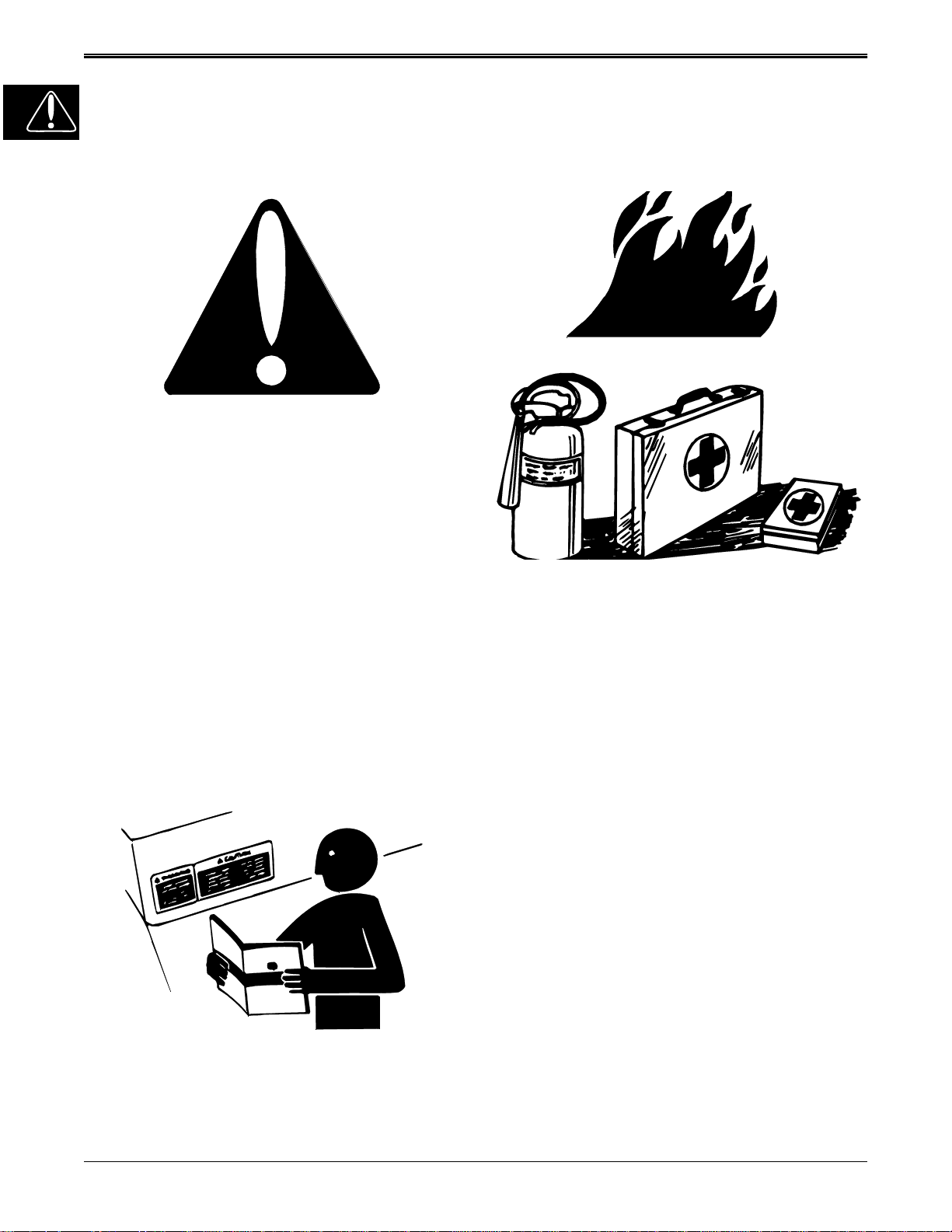
RECOGNIZE SAFETY INFORMATION
This is the safety-alert symbol. When you see this symbol on your machine or in this manual, be alert to the potential for personal injury.
Follow recommended precautions and safe servicing
practices.
HANDLE FLUIDS SAFELY-AVOID
FIRES
BE PREPARED FOR EMERGENCIES
UNDERSTAND SIGNAL WORDS
A signal word—DANGER, WARNING, or CAUTION—is
used with the safety-alert symbol. DANGER identifies
the most serious hazards.
DANGER or WARNING safety signs are located near
specific hazards. General precautions are listed on
CAUTION safety signs. CAUTION also calls attention to
safety messages in this manual.
REPLACE SAFETY SIGNS
When you work around fuel, do not smoke or work near
heaters or other fire hazards.
Store flammable fluids away from fire hazards. Do not
incinerate or puncture pressurized containers.
Make sure machine is clean of trash, grease, and debris.
Do not store oily rags; they can ignite and burn spontaneously.
Be prepared if a fire starts.
Keep a first aid kit and fire extinguisher handy.
Keep emergency numbers for do ctors, am bulance s ervice, hospital, and fire departme nt near yo ur telep hone.
Replace missing or damaged safety signs. See the machine operator’s manual for correct safety sign placement.
1 - 2
9/25/00
Page 5
SAFETY
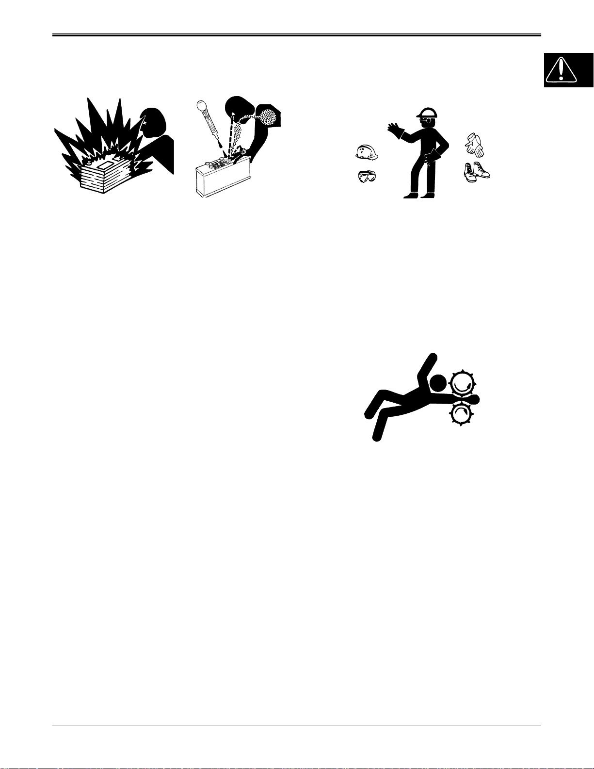
USE CARE IN HANDLING AND
SERVICING BATTERIES
PREVENT BATTERY EXPLOSIONS
• Keep sparks, lighted matches, and open flame
away from the top of battery. Battery gas can
explode.
• Never check battery charge by placing a metal
object across the posts. Use a volt-meter or
hydrometer.
• Do not charge a frozen battery; it may explode.
Warm battery to 16°C (60°F).
PREVENT ACID BURNS
• Sulfuric acid in battery electroly te is poisonous. It is
strong enough to burn skin, eat holes in clothing,
and cause blindness if splashed into eyes.
USE SAFE SERVICE PROCEDURES
WEAR PROTECTIVE CLOTHING
Wear close fitting clothing and safety equipment appropriate to the job.
Prolonged exposure to loud noise can cause impairment or loss of hearing. Wear a suitable hearing protective device such as earmuffs or earplugs to protect
against objectionable or uncomfortable loud noises.
Operating equipment safely requires the full attention of
the operator. Do not wear radio or music headphones
while operating machine.
SERVICE MACHINES SAFELY
• Avoid acid burns by:
1. Filling batteries in a well-ventilated area.
2. Wearing eye protection and rubber gloves.
3. Av oiding brea thing fumes when ele ctrolyte is
added.
4. Avoiding spilling or dripping electrolyte.
5. Use proper jump start procedure.
• If you spill acid on yourself:
1. Flush your skin with water.
2. Apply baking soda or lime to help neutr aliz e the
acid.
3. Flush your eyes with water for 10_15 minutes.
4. Get medical attention immediately.
• If acid is swallowed:
1. Drink large amounts of water or milk.
2. Then drink milk of magnesia, beaten eggs, or
vegetable oil.
3. Get medical attention immediately.
Tie long hair behind your head. Do not wear a necktie,
scarf, loose clothing, or necklace when you work near
machine tools or moving parts . If these items were to
get caught, severe injury could result.
Remove rings and other jewelry to prevent electrical
shorts and entanglement in moving parts.
USE PROPER TOOLS
Use tools appropriate to the work. Makeshift tools and
procedures can create safety hazards. Use power tools
only to loosen threaded parts and fasteners. For loosening and tightening hardware, use the correct size tools.
DO NOT use U.S. measurement tool s on metric fasteners. Avoid bodily injury caused by slipping wrenches.
Use only service parts meeting John Deere specifications.
9/25/00
1 - 3
Page 6
SAFETY
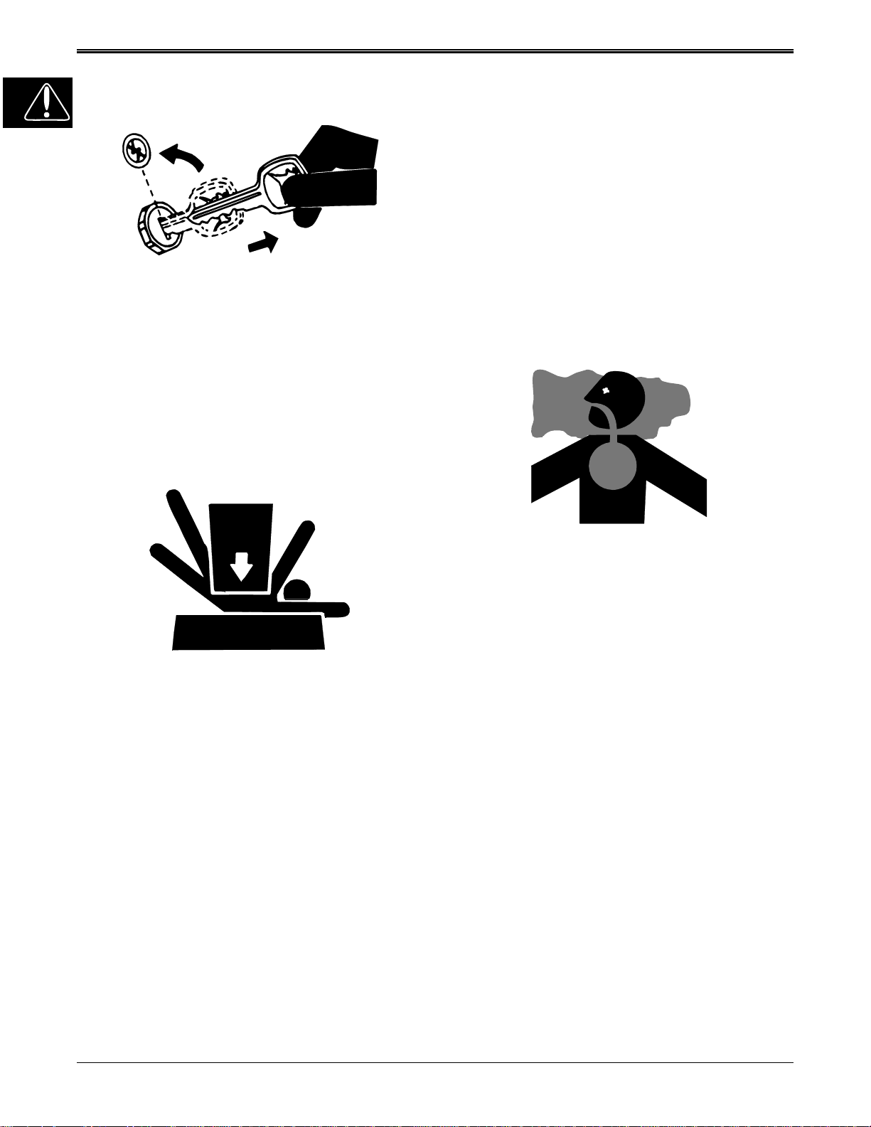
PARK MACHINE SAFELY
Before working on the machine:
1. Lower all equipment to the ground.
2. Stop the engine and remove the key.
3. Disconnect the battery ground strap.
4. Hang a “DO NOT OPERATE” tag in operator
station.
SUPPORT MA CHINE PROPERLY AND USE
PROPER LIFTING EQUIPMENT
USING HIGH PRESSURE WASHERS
Directing pressurized water at electronic/ele ctrical components or connectors, bearings, hydraulic seals, fuel
injection pumps or other sensitive parts and components may cause product malfunctions. Reduce pressure and spray at a 45 to 90 degree angle.
ILLUMINATE WORK AREA SAFELY
Illuminate your work area adequately but safely. Use a
portable safety light for working inside or under the machine. Make sure the bulb is enclos ed by a wire cage.
The hot filament of an accidentally broken bulb can ignite spilled fuel or oil.
WORK IN VENTILATED AREA
If you must work on a lifted machine or attachment, securely support the machine or attachment.
Do not support the machine on cinder blocks, hollow
tiles, or props that may crumble under continuous load.
Do not work under a machine that is supported solely by
a jack. Follow recommended procedures in this manual.
Lifting heavy components incorrectly can cause severe
injury or machine damage. Follow recommended procedure for removal and installatio n of components in the
manual.
WORK IN CLEAN AREA
Before starting a job:
1. Clean work area and machine.
2. Make sure you ha v e all necessary tools to do your
job.
3. Have the right parts on hand.
4. Read all instructions thoroughly; do not attempt
shortcuts.
Engine exhaust fumes can cause sickness or death. If it
is necessary to run an engine in an enclosed area, remove the exhaust fumes from the area with an exhaust
pipe extension.
If you do not have an exhaust pipe extension, open the
doors and get outside air into the area.
W ARNING: CALIFORNIA PROPOSITION 65
WARNING
Gasoline engine exhaust from this product contains
chemicals known to the State of California to cause cancer, birth defects, or other reproductive harm.
REMOVE PAINT BEFORE WELDING OR
HEATING
Avoid potentially toxic fumes and dust. Hazardous
fumes can be generated when paint is heated by welding, soldering, or using a torch. Do all work outside or in
a well ventilated area. Dispose of paint and solvent
properly. Remove paint before welding or heating : If you
sand or grind paint, avoid breathing the dust. Wear an
approved respirator. If you use solvent or paint stri pper,
remove stripper with soap and water before welding.
Remove solvent or paint stripper containers and other
flammable material from area. Allo w fumes to dispe rse
at least 15 minutes before welding or heating.
1 - 4
9/25/00
Page 7
SAFETY
AVOID HARMFUL ASBESTOS DUST
Avoid breathing dust that may be generated when
handling components containing asbestos fibers.
Inhaled asbestos fibers may cause lung cancer.
Components in products that may contain asbestos
fibers are brake pads, brake band and lining assemblies, clutch plates, and some gask ets. The asbestos
used in these components is usually found in a resin or
sealed in some way. Normal handling is not hazardous
as long as airborne dust containing asbestos is not
generated.
Avoid creating dust. Never use compressed air for
cleaning. Avoid brushing or grinding material containing
asbestos. When servicing, wear an appr oved respirator. A special vacuum cleaner is recommended to clean
asbestos. If not available, apply a mist of oil or water on
the material containing asbestos. Keep bystanders
away from the area.
SERVICE TIRES SAFELY
AVOID INJURY FROM ROTATING
BLADES, AUGERS AND PTO
SHAFTS
Keep hands and feet away while machine is running.
Shut off power to service, lubricate or remove mower
blades, augers or PTO shafts.
HANDLE CHEMICAL PRODUCTS
SAFELY
Explosive separation of a tire and rim parts can cause
serious injury or death.
Do not attempt to mount a tire u nless you have the proper equipment and experience to perform the job.
Always maintain the correct tire pressure. Do not inflate
the tires above the recommended pressure. Never we ld
or heat a wheel and tire assembly. The heat can cause
an increase in air pressure resulting in a tire explosion.
Welding can structurally weaken or deform the wheel.
When inflating tires, use a clip-o n chuck an d extens ion
hose long enough to allow you to stand to one side and
NOT in front of or over the tire assembly. Use a safety
cage if available.
Check wheels for low pressure, cuts, bubbles, damaged
rims or missing lug bolts and nuts.
Direct exposure to hazardous chemicals can cause serious injury. Potentially hazardous chemicals used with
John Deere equipment include such items as lubricants,
coolants, paints, and adhesives.
A Material Safety Data Sheet (MSDS) provides specific
details on chemical products: physical and health hazards, safety procedures, and emergency response
techniques. Check the MSDS before you start any job
using a hazardous chemical. That way you will know exactly what the risks are and how to do the job safely.
Then follow procedures and recommended equipment.
9/25/00
1 - 5
Page 8

SAFETY
DISPOSE OF WASTE PROPERLY
Improperly disposing of waste can threaten the environment and ecology. Potentially harmful waste used with
John Deere equipment include such items as oil, fuel,
coolant, brake fluid, filters, and batteries. Use le akproof
containers when draining fluids. Do not use food or beverage containers that may mislead someone into drinking from them. Do not pour waste onto the ground,
down a drain, or into any water source. Inquire on the
proper way to recycle or dispose of waste from your local environmental or recycling center, or fro m your John
Deere dealer.
LIVE WITH SAFETY
Before returning machine to customer, make sure machine is functioning properly, especially the safety systems. Install all guards and shields.
1 - 6
9/25/00
Page 9

SPECIFICATIONS AND INFORMATION
GENERAL VEHICLE SPECIFICATIONS . . . . . . . . . . . . . . . . . . . . . . . . . 3
METRIC FASTENER TORQUE VALUES . . . . . . . . . . . . . . . . . . . . . . . . . . . . . . . . . . 6
METRIC FASTENER TORQUE VALUE—GRADE 7. . . . . . . . . . . . . . . . . . . . . . . . . . 7
INCH FASTENER TORQUE VALUES. . . . . . . . . . . . . . . . . . . . . . . . . . . . . . . . . . . . . 8
GASOLINE . . . . . . . . . . . . . . . . . . . . . . . . . . . . . . . . . . . . . . . . . . . . . . . . 9
GASOLINE STORAGE . . . . . . . . . . . . . . . . . . . . . . . . . . . . . . . . . . . . . . . . . . . . . . . . 9
LUBRICANTS . . . . . . . . . . . . . . . . . . . . . . . . . . . . . . . . . . . . . . . . . . . . . 10
ENGINE OIL - KOHLER ENGINE . . . . . . . . . . . . . . . . . . . . . . . . . . . . . . . . . . . . . . . 10
ENGINE OIL - BRIGGS & STRATTON ENGINE. . . . . . . . . . . . . . . . . . . . . . . . . . . . 10
ENGINE BREAK–IN OIL . . . . . . . . . . . . . . . . . . . . . . . . . . . . . . . . . . . . . . . . . . . . . . 11
ANTI-CORROSION GREASE. . . . . . . . . . . . . . . . . . . . . . . . . . . . . . . . . . . . . . . . . . 11
ALTERNATIVE LUBRICANTS. . . . . . . . . . . . . . . . . . . . . . . . . . . . . . . . . . . . . . . . . .12
SYNTHETIC LUBRICANTS. . . . . . . . . . . . . . . . . . . . . . . . . . . . . . . . . . . . . . . . . . . . 12
LUBRICANT STORAGE . . . . . . . . . . . . . . . . . . . . . . . . . . . . . . . . . . . . . . . . . . . . . . 12
MIXING OF LUBRICANTS . . . . . . . . . . . . . . . . . . . . . . . . . . . . . . . . . . . . . . . . . . . . 12
CHASSIS GREASE. . . . . . . . . . . . . . . . . . . . . . . . . . . . . . . . . . . . . . . . . . . . . . . . . . 12
GEAR TRANSMISSION GREASE . . . . . . . . . . . . . . . . . . . . . . . . . . . . . . . . . . . . . . 13
HYDROSTATIC TRANSMISSION OIL. . . . . . . . . . . . . . . . . . . . . . . . . . . . . . . . . . . . 13
SERIAL NUMBER LOCATION . . . . . . . . . . . . . . . . . . . . . . . . . . . . . . . . 14
CONTENTS
CONTENTS
Page
SPECIFICATIONS
9/25/00
2 - 1
Page 10

NOTES
SPECIFICATIONS AND INFORMATION
2 - 2
9/25/00
Page 11

SPECIFICATIONS AND INFORMATION
GENERAL VEHICLE SPECIFICATIONS
ENGINE SPECIFICATIONS
KOHLER ENGINES—LT 133 and LT155
Make . . . . . . . . . . . . . . . . . . . . . . . . . . . . . . . . . . . . . . . . . . . . . . . . . . . . . . . . . . . Kohler
Model / Model Number:
LT133. . . . . . . . . . . . . . . . . . . . . . . . . . . . . . . . . . . . . . . Command LT / CV13S-21525
LT155. . . . . . . . . . . . . . . . . . . . . . . . . . . . . . . . . . . .Command 15 QT / CV15S-41562
Power:
LT133. . . . . . . . . . . . . . . . . . . . . . . . . . . . . . . . . . . . . . . . . . . . . . . . . 9.7 kW (13.0 hp)
LT155. . . . . . . . . . . . . . . . . . . . . . . . . . . . . . . . . . . . . . . . . . . . . . . . 11.2 kW (15.0 hp)
Displacement:
LT133. . . . . . . . . . . . . . . . . . . . . . . . . . . . . . . . . . . . . . . . . . . . . .398 cm
LT155. . . . . . . . . . . . . . . . . . . . . . . . . . . . . . . . . . . . . . . . . . . . . .426 cm
Cylinders . . . . . . . . . . . . . . . . . . . . . . . . . . . . . . . . . . . . . . . . . . . . . . . . . . . . . . . . . . . . 1
Stroke/Cycle . . . . . . . . . . . . . . . . . . . . . . . . . . . . . . . . . . . . . . . . . . . . . . . . . . . . . . . . . 4
Valves . . . . . . . . . . . . . . . . . . . . . . . . . . . . . . . . . . . . . . . . . . . . . . . . . .Overhead Valves
Lubrication. . . . . . . . . . . . . . . . . . . . . . . . . . . . . . . . . . . . . . . . . . . . . . . . . . .Pressurized
Oil Filter. . . . . . . . . . . . . . . . . . . . . . . . . . . . . . Single Element, Full Flow, Spin-On Filter
Crankcase Capacity (With Filter) . . . . . . . . . . . . . . . . . . . . . . . . . . . . . . . . 1.8 L (1.9 qt)
Without Filter. . . . . . . . . . . . . . . . . . . . . . . . . . . . . . . . . . . . . . . . . . . . . . 1.4 L (1.5 qt)
Cooling System. . . . . . . . . . . . . . . . . . . . . . . . . . . . . . . . . . . . . . . . . . . . . . . . Air Cooled
Air Cleaner . . . . . . . . . . . . . . . . . . . . . . . . . . . . . . . . . . . Paper with outer foam element
Muffler. . . . . . . . . . . . . . . . . . . . . . . . . . . . . . . . . . . . .Horizontal discharge below frame
Spark Plug Gap. . . . . . . . . . . . . . . . . . . . . . . . . . . . . . . . . . . . . . . . . . 1.0 mm (0.040 in.)
GENERAL VEHICLE SPECIFICATIONS
3
(24.3 cu-in.)
3
(26.0 cu-in.)
BRIGGS & STRATTON—LT166
Make . . . . . . . . . . . . . . . . . . . . . . . . . . . . . . . . . . . . . . . . . . . . . . . . . . .Briggs & Stratton
Series . . . . . . . . . . . . . . . . . . . . . . . . . . . . . . . . . . . . . . . . . . . . . . . . . . Vanguard V-Twin
Type. . . . . . . . . . . . . . . . . . . . . . . . . . . . . . . . . . . . . . . . . . . . . . . . . . . .916928 Gasoline
Model . . . . . . . . . . . . . . . . . . . . . . . . . . . . . . . . . . . . . . . . . . . . . . . . . . . . . . . . . 303777
Horsepower. . . . . . . . . . . . . . . . . . . . . . . . . . . . . . . . . . . . . . . . . . . . . 11.9 kW (16.0 hp)
Displacement . . . . . . . . . . . . . . . . . . . . . . . . . . . . . . . . . . . . . . . . 480 cm
Cylinders . . . . . . . . . . . . . . . . . . . . . . . . . . . . . . . . . . . . . . . . . . . . . . . . . . . . . . . . . . . . 2
Stroke/Cycle . . . . . . . . . . . . . . . . . . . . . . . . . . . . . . . . . . . . . . . . . . . . . . . . . . . . . . . . . 4
Valves . . . . . . . . . . . . . . . . . . . . . . . . . . . . . . . . . . . . . . . . . . . . . . . . . .Overhead Valves
Lubrication. . . . . . . . . . . . . . . . . . . . . . . . . . . . . . . . . . . . . . . . . . . . . . . . . . .Pressurized
Oil Filter. . . . . . . . . . . . . . . . . . . . . . . . . . . . . . . . . . Full Flow Filter (w/o By-Pass Valve)
Crankcase Capacity (With Filter) . . . . . . . . . . . . . . . . . . . . . . . . . . . . . . . . 1.5 L (1.6 qt)
Without Filter. . . . . . . . . . . . . . . . . . . . . . . . . . . . . . . . . . . . . . . . . . . . . . 1.4 L (1.5 qt)
Cooling System. . . . . . . . . . . . . . . . . . . . . . . . . . . . . . . . . . . . . . . . . . . . . . . . Air Cooled
Air Cleaner . . . . . . . . . . . . . . . . . . . . . . . . . . . . . . . . . . . Paper with outer foam element
Muffler. . . . . . . . . . . . . . . . . . . . . . . . . . . . . . . . . . . . .Horizontal discharge below frame
Spark Plug Gap. . . . . . . . . . . . . . . . . . . . . . . . . . . . . . . . . . . . . . . . . . 1.0 mm (0.040 in.)
ELECTRICAL
Ignition. . . . . . . . . . . . . . . . . . . . . . . . . . . .Electronic Capacitor Discharge Ignition (CDI)
Type of Starter. . . . . . . . . . . . . . . . . . . . . . . . . . . . . . . . . . . . . . . . . . . . . . . . . . . . Bendix
Charging System. . . . . . . . . . . . . . . . . . . . . . . . . . . . . . . . . . . . . . . . Flywheel Alternator
3
(29.3 cu. in.)
9/25/00
2 - 3
Page 12

GENERAL VEHICLE SPECIFICATIONS
FUEL SYSTEM
Aspiration . . . . . . . . . . . . . . . . . . . . . . . . . . . . . . . . . . . . . . . . . . . . . . . . . . . . . . .Natural
Fuel Tank Location . . . . . . . . . . . . . . . . . . . . . . . . . . . . . . . . . . . . . . . . . . . . . . . . . .Rear
Fuel Tank Capacity . . . . . . . . . . . . . . . . . . . . . . . . . . . . . . . . . . . . . . . . . . 7.5 L (2.0 gal)
Fuel Type (minimum octane). . . . . . . . . . . . . . . . . . . . . . Unleaded Gasoline, 87 Octane
Fuel Delivery . . . . . . . . . . . . . . . . . . . . . . . . . . . . . . . . .Float-Type Side Draft Carburetor
Fuel Filter . . . . . . . . . . . . . . . . . . . . . . . . . . . . . . . . . . . . . . . . . . . . .Replaceable In-Line
Fuel Filler Opening/Location. . . . . . . . . . . . . . 7.6 cm (3 in.) Diameter/Left Rear Fender
Battery:
Voltage . . . . . . . . . . . . . . . . . . . . . . . . . . . . . . . . . . . . . . . . . . . . . . . . . . . . . . . . . . . . 12
BCI group . . . . . . . . . . . . . . . . . . . . . . . . . . . . . . . . . . . . . . . . . . . . . . . . . . . . . . . . . .U-1
CCA rating (Amps At -18°C (0°F) . . . . . . . . . . . . . . . . . . . . . . . . . . . . . . . . . . . . . . . 160
Reserve capacity (Minutes At 25 Amps). . . . . . . . . . . . . . . . . . . . . . . . . . . . . . . . . . . 20
Specific gravity (Minimum) . . . . . . . . . . . . . . . . . . . . . . . . . . . . . . . . . . . . . .1.225 points
Electrolyte required fill (Approximate) . . . . . . . . . . . . . . . . . . . . . . . . . . . . . 1.9 L (2.0 qt)
Load test (Minimum) . . . . . . . . . . . . . . . . . . . . . . . . . . . . . . . . . 255 amp for 15 seconds
POWER TRAIN SPECIFICATIONS
Gear Transaxle:
Make . . . . . . . . . . . . . . . . . . . . . . . . . . . . . . . . . . . . . . . . . . . . . . . . . . . . . . . . . . . . Dana
Model . . . . . . . . . . . . . . . . . . . . . . . . . . . . . . . . . . . .Spicer Heavy-Duty 4360 Transaxle
Type. . . . . . . . . . . . . . . . . . . . . . . . . . . . . . . . . . . . . . . . . . . . . . .Five-Speed/Linear Shift
Ground Speeds (At Fast Idle—3350 rpm) and Gear Ratios:
1st Gear . . . . . . . . . . . . . . . . . . . . . . . . . . . . . . . . . . . . . 2.5 km/hr (1.6 mph)—61.67:1
2nd Gear. . . . . . . . . . . . . . . . . . . . . . . . . . . . . . . . . . . . . 3.3 km/hr (2.1 mph)—46.67:1
3rd Gear . . . . . . . . . . . . . . . . . . . . . . . . . . . . . . . . . . . . . 5.2 km/hr (3.2 mph)—30.00:1
4th Gear . . . . . . . . . . . . . . . . . . . . . . . . . . . . . . . . . . . . . 6.6 km/hr (4.1 mph)—23.48:1
5th Gear . . . . . . . . . . . . . . . . . . . . . . . . . . . . . . . . . . . . . 8.5 km/hr (5.3 mph)—18.46:1
Reverse . . . . . . . . . . . . . . . . . . . . . . . . . . . . . . . . . . . . . 3.9 km/hr (2.4 mph)—40.00:1
Brake Type . . . . . . . . . . . . . . . . . .Single, External Brake Disc With Dual Friction Pucks
Lubrication—Input Shaft Needle Bearings . . . . . . Unirex® N3 Grease Only (M120263)
Lubrication—Transaxle . . . . . . . . . . . . . . . . .Shell Darina® D Grease Only (AM119608)
Capacity—Transaxle . . . . . . . . . . . . . . . . . . . . . . . . . . . . . . . . . . . . . .0.64 kg (1.406 lbs)
Hydrostatic Transaxle:
Drive Train . . . . . . . . . . . . .Belt Drive Transaxle with foot-controlled variable speed drive
Model . . . . . . . . . . . . . . . . . . . . . . . . . . . . . . . . . . . . . . . . . . . .Tuff Torq
Travel Speed-Forward. . . . . . . . . . . . . . . . . . . . . . . . . . . . . . . . . 0-8.8 km/h (0-5.5 mph)
Travel Speed-Reverse. . . . . . . . . . . . . . . . . . . . . . . . . . . . . . . . . 0-4.7 km/h (0-3.0 mph)
Brake type. . . . . . . . . . . . . . . . . . . . . . . . . . . . . . . . . . . .Single, Internal Wet Disc Brake
PTO Drive:
Type. . . . . . . . . . . . . . . . . . . . . . . . . . . . . . . . . . . . . . . . . . . . . . . . . . . . . . . . . . . . .V-Belt
Clutch Type . . . . . . . . . . . . . . . . . . . . . . . . . . . . . . . . . . . . . . . . . . . . . . . . . . Mechanical
Control. . . . . . . . . . . . . . . . . . . . . . . . . . . . . . . . . . . . . . . . . . . . . . . . . . . .Lever on Dash
SPECIFICATIONS AND INFORMATION
®
K51 Transaxle
2 - 4
STEERING
Type. . . . . . . . . . . . . . . . . . . . . . . . . . . . . . . . . . . . . . . . . . . . . . . . . . . Sector and Pinion
Turning Radius . . . . . . . . . . . . . . . . . . . . . . . . . . . . . . . . . . . . . . . . . . . . 38.1 cm (15 in.)
IMPLEMENT LIFT
Lift System . . . . . . . . . . . . . . . . . . . . . . . . . . . . . . . . . . . . . . . . . . . . . . . . . . . . . .Manual
Lift Lever Location. . . . . . . . . . . . . . . . . . . . . . . . . . . . . . . . . . . . .Left-hand side of hood
9/25/00
Page 13

SPECIFICATIONS AND INFORMATION
TIRES
Size-Front . . . . . . . . . . . . . . . . . . . . . . . . . . . . . . . . . . . . . . . . . . . . . . . . . . 15 x 6.00 - 6
Size-Rear . . . . . . . . . . . . . . . . . . . . . . . . . . . . . . . . . . . . . . . . . . . . . . . . . 20 x 10.00 - 8
Pressure-Front (with mower). . . . . . . . . . . . . . . . . . . . . . . . . . . . . . . . . . 83 kPa (12 psi)
Pressure-Rear (with mower) . . . . . . . . . . . . . . . . . . . . . . . . . . . . . . . . . . . 55 kPa (8 psi)
NET WEIGHT (NO FUEL)
LT133 with 38” deck . . . . . . . . . . . . . . . . . . . . . . . . . . . . . . . . . . . . . . 206.8 kg (455 lbs)
LT155 with 38” deck . . . . . . . . . . . . . . . . . . . . . . . . . . . . . . . . . . . . . . 213.6 kg (470 lbs)
LT155 with 42” deck . . . . . . . . . . . . . . . . . . . . . . . . . . . . . . . . . . . . . . 215.9 kg (475 lbs)
LT166 with 42” deck . . . . . . . . . . . . . . . . . . . . . . . . . . . . . . . . . . . . . . 215.9 kg (475 lbs)
LT166 with 46” deck . . . . . . . . . . . . . . . . . . . . . . . . . . . . . . . . . . . . . . 220.5 kg (485 lbs)
38 INCH MOWER DECK
Ty pe. . . . . . . . . . . . . . . . . . . . . . . . . . . . . . . . . . . . . . . . . . . . . . . . . Rotary - Convertible
Cutting Blade. . . . . . . . . . . . . . . . . . . . . . . . . Two—76 x 5 x 496 mm (3 x 0.2 x 19.5 in.)
Blade Cutting Edge . . . . . . . . . . . . . . . . . . . . . . . . . . . . . . . . . . . . . . . . . . .30 ± 5° Angle
Overall Cutting Width . . . . . . . . . . . . . . . . . . . . . . . . . . . . . . . . . . . . . . . 96.5 cm (38 in.)
Cutting Settings. . . . . . . . . . . . . . . . . . . . . . . . . . . .Thirteen: 25—102 mm (1.0—4.0 in.)
GENERAL VEHICLE SPECIFICATIONS
42 INCH MOWER DECK
Type. . . . . . . . . . . . . . . . . . . . . . . . . . . . . . . . . . . . . Rotary—Double Spindles, Mulching
Blade Cutting Edge . . . . . . . . . . . . . . . . . . . . . . . . . . . . . . . . . . . . . . . . . . .30 ± 5° Angle
Overall Cutting Width . . . . . . . . . . . . . . . . . . . . . . . . . . . . . . . . . . . . . . 106.8 cm (42 in.)
Cutting Settings. . . . . . . . . . . . . . . . . . . . . . . . . . . .Thirteen: 25—102 mm (1.0—4.0 in.)
46 INCH MOWER DECK
Ty pe. . . . . . . . . . . . . . . . . . . . . . . . . . . . . . . . . . . . . . . . . . . . . . . . . Rotary - Convertible
Cutting Blade. . . . . . . . . . . . . . . . . . . . . . Three—50.8 x 5 x 407.4 mm (2 x 0.2 x 16 in.)
Blade Cutting Edge . . . . . . . . . . . . . . . . . . . . . . . . . . . . . . . . . . . . . . . . . . .30 ± 5° Angle
Overall Cutting Width . . . . . . . . . . . . . . . . . . . . . . . . . . . . . . . . . . . . . . 116.8 cm (46 in.)
Cutting Settings. . . . . . . . . . . . . . . . . . . . . . . . Thirteen: 25 mm—102 mm (1.0—4.0 in.)
48C INCH MOWER DECK
Ty pe. . . . . . . . . . . . . . . . . . . . . . . . . . . . . . . . . . . . . . . . . . . . . . . . . Rotary - Convertible
Cutting Blade. . . . . . . . . . . . . . . . . . . . . . Three—50.8 x 5 x 407.4 mm (2 x 0.2 x 16 in.)
Blade Cutting Edge . . . . . . . . . . . . . . . . . . . . . . . . . . . . . . . . . . . . . . . . . . .30 ± 5° Angle
Overall Cutting Width . . . . . . . . . . . . . . . . . . . . . . . . . . . . . . . . . . . . . . 121.9 cm (48 in.)
Cutting Settings. . . . . . . . . . . . . . . . . . . . . . . . Thirteen: 25 mm—102 mm (1.0—4.0 in.)
9/25/00
2 - 5
Page 14

GENERAL VEHICLE SPECIFICATIONS
METRIC FASTENER TORQUE VALUES
SPECIFICATIONS AND INFORMATION
4.8
8.8
9.8
10.9
12.9
Property
Class
and
Head
Markings
Property
4.8
4.8
8.8
8.8
5
9.8
9.8
10
10.9
10.9
10
12.9
12.9
12.9
12
Class
and
Nut
Markings
Class 4.8 Class 8.8 or 9.8 Class 10.9 Class 12.9
Lubricated
SIZE N•m lb-ft N•mlb-ft N•m lb-ft N•mlb-ft N•m lb-ft N•mlb-ft N•m lb-ft N•mlb-ft
4.8 3.5 6 4.5 9 6.5 11 8.5 13 9.5 17 12 15 11.5 19 14.5
M6
12 8.5 15 11 22 16 28 20 32 24 40 30 37 28 47 35
M8
23 17 29 21 43 32 55 40 63 47 80 60 75 55 95 70
M10
40 29 50 37 75 55 95 70 110 80 140 105 130 95 165 120
M12
5
a
Dry
5
10
a
Lubricated
a
Dry
a
10
10
Lubricated
10
12
a
Dry
a
Lubricated
12
TS1163
a
Dry
a
63 47 80 60 120 88 150 110 175 130 225 165 205 150 260 109
M14
100 73 125 92 190 140 240 175 275 200 350 225 320 240 400 300
M16
135 100 175 125 260 195 330 250 375 275 475 350 440 325 560 410
M18
190 140 240 180 375 275 475 350 530 400 675 500 625 460 800 580
M20
260 190 330 250 510 375 650 475 725 540 925 675 850 625 1075 800
M22
330 250 425 310 650 475 825 600 925 675 1150 850 1075 800 1350 1000
M24
490 360 625 450 950 700 1200 875 1350 1000 1700 1250 1600 1150 2000 1500
M27
675 490 850 625 1300 950 1650 1200 1850 1350 2300 1700 2150 1600 2700 2000
M30
900 675 1150 850 1750 1300 2200 1650 2500 1850 3150 2350 2900 2150 3700 2750
M33
1150 850 1450 1075 2250 1650 2850 2100 3200 2350 4050 3000 3750 2750 4750 3500
M36
DO NOT use these hand torque values if a different
torque value or tightening procedure is given for a
specific application. Torque values listed are for gen eral
use only and include a ±10% variance factor. Check
tightness of fasteners periodically. DO NOT use air
powered wrenches.
Shear bolts are designed to fail under predetermined
loads. Always replace shear bolts with identical grade.
Fasteners should be replaced with the same class.
Make sure fastener threads are clean and that you
properly start thread engagement. This will prevent
them from failing when tightening.
When bolt and nut combination fasteners are used,
torque values should be applied to the NUT instead of
the bolt head.
Tighten toothed or serrated-type lock nuts to the full
torque value.
a
“Lubricated” means coated with a lubricant such
as engine oil, or fasteners with phosphate and oil
coatings. “Dry” means plain or zinc plated (Yellow
Dichromate - Specification JDS117) without any
lubrication
Reference: JDS —G200
.
2 - 6
9/25/00
Page 15

SPECIFICATIONS AND INFORMATION
GENERAL VEHICLE SPECIFICATIONS
METRIC FASTENER TORQUE VALUE—GRADE 7
Steel or Gray
Size
M6 11 8 8 6
M8 24 18 19 14
M10 52 38 41 30
M12 88 65 70 52
M14 138 102 111 82
M16 224 165 179 132
Iron Torque
N•m lb-ft N•m lb-ft
Aluminum
Torque
9/25/00
2 - 7
Page 16

GENERAL VEHICLE SPECIFICATIONS
INCH FASTENER TORQUE VALUES
SPECIFICATIONS AND INFORMATION
SAE
1 or 2
b
5
5.1
5.2
8
8.2
Grade
and Head
No Marks
Markings
2
5
8
SAE
Grade
and Nut
No Marks
Markings
TS1162
Grade 1 Grade 2
Lubricated
SIZE N•m lb-ft N•mlb-ft N•m lb-ft N•mlb-ft N•m lb-ft N•mlb-ft N•m lb-ft N•mlb-ft
1/4
5/16
3/8
7/16
1/2
3.7 2.8 4.7 3.5 6 4.5 7.5 5.5 9.5 712913.5 10 17 12.5
7.7 5.5 10 7 12 9151120 15 25 18 28 21 35 26
14 10 17 13 22 16 27 20 35 26 44 33 50 36 63 46
22 16 28 20 35 26 44 32 55 41 70 52 80 58 100 75
33 25 42 31 53 39 67 50 85 63 110 80 120 90 150 115
a
Dry
a
b
Lubricated
Grade 5, 5.1 or 5.2 Grade 8 or 8.2
a
Dry
a
Lubricated
a
Dry
a
Lubricated
a
Dry
a
9/16
5/8
3/4
7/8
1
1-1/8
1-1/4
1-3/8
1-1/2
48 36 60 45 75 56 95 70 125 90 155 115 175 130 225 160
67 50 85 62 105 78 135 100 170 125 215 160 215 160 300 225
120 87 150 110 190 140 240 175 300 225 375 280 425 310 550 400
190 140 240 175 190 140 240 175 490 360 625 450 700 500 875 650
290 210 360 270 290 210 360 270 725 540 925 675 1050 750 1300 975
470 300 510 375 470 300 510 375 900 675 1150 850 1450 1075 1850 1350
570 425 725 530 570 425 725 530 1300 950 1650 1200 2050 1500 2600 1950
750 550 950 700 750 550 950 700 1700 1250 2150 1550 2700 2000 3400 2550
1000 725 1250 925 990 725 1250 930 2250 1650 2850 2100 3600 2650 4550 3350
DO NOT use these hand torque values if a different
torque value or tightening procedure is given for a
specific application. Torque values listed are for gen eral
use only and include a ±10% variance factor. Check
tightness of fasteners periodically. DO NOT use air
powered wrenches.
Shear bolts are designed to fail under predetermined
loads. Always replace shear bolts with identical grade.
Fasteners should be replaced with the same grade.
Make sure fastener threads are clean and that you
properly start thread engagement. This will prevent
them from failing when tightening.
When bolt and nut combination fasteners are used,
torque values should be applied to the NUT instead of
the bolt head.
Tighten toothed or serrated-type lock nuts to the full
torque value.
a
“Lubricated” means coated with a lubricant such
as engine oil, or fasteners with phosphate and oil
coatings. “Dry” means plain or zinc plated (yellow
dichromate - Specification JDS117) without any
.
lubrication
b
“Grade 2” applies for hex cap screws (Not
Hex Bolts) up to 152 mm (6—in.) long. “Grade
1” applies for hex cap screws over 152 mm
(6—in.) long, and for all other types of bolts
and screws of any length.
Reference: JDS —G200
2 - 8
9/25/00
Page 17

SPECIFICATIONS AND INFORMATION
GASOLINE
GASOLINE
c
Gasoline is HIGHLY FLAMMABLE, handle it with care.
DO NOT refuel machine while:
• indoors, always fill gas tank outdoors
• machine is near an open flame or sparks
• engine is running, STOP engine
• engine is hot, allow it to cool sufficiently first
• smoking
Help prevent fires:
• fill gas tank to bottom of filler neck only
• be sure fill cap is tight after fueling
• clean up any gas spills IMMEDIATELY
• keep machine clean and in good repair—free of excess grease, oil, debris, and faulty or damaged
parts
• any storage of machines with gas left in tank should be in an area that is well ventilated to prevent
possible igniting of fumes by an open flame or spark, this includes any appliance with a pilot light
To prevent fire or explosion caused by STATIC ELECTRIC DISCHARGE during fueling:
• ONLY use a clean, approved POLYETHYLENE PLASTIC fuel container and funnel WITHOUT any metal
screen or filter
CAUTION
STOP ENGINE
NO OPEN FLAME
OR SPARK
NO HOT ENGINE
NO SMOKING
NO STATIC ELECTRIC
DISCHARGE
To avoid engine damage:
• DO NOT mix oil with gasoline
• ONLY use clean, fresh unleaded gasoline with
an octane rating (anti-knock index) of 87 or
higher
• fill gas tank at the end of each day's operation to
help prevent condensation from forming inside a
partially filled tank
• keep up with specified service intervals
Use of alternative oxygenated, gasohol blended,
unleaded gasoline is acceptable as long as:
• the ethyl or grain alcohol blends DO NOT exceed
10% by volume or
• methyl tertiary butyl ether (MTBE) blends DO NOT
exc eed 15% by volum e
IMPORTANT: DO NOT use METHANOL gasolines
because METHANOL is harmful to the
environment and to your health.
c
California Proposition 65 Warning: Gasoline
engine exhaust from this product contains
chemicals known to the State of California to
cause cancer, birth defects, or other
reproductive harm.
WARNING
GASOLINE STORAGE
IMPORTANT: Keep all dirt, scale, water or other
foreign material out of gasoline.
Keep gasoline stored in a safe, protected area. Storage
of gasoline in a clean, properly marked (“UNLEADED
GASOLINE”) POLYETHYLENE PLASTIC container
WITHOUT any metal screen or filter is recommended.
DO NOT use de-icers to attempt to remove water from
gasoline or depend on fuel filters to remove water from
gasoline. Use a water separator installed in the stor age
tank outlet. BE SURE to properly discard unstable or
contaminated gasoline. When storing unit or gasoline,
it is recommended that you add John Deere Gasoline
Conditioner and Stabilizer (TY15977) or an
equivalent to the gasoline. BE SURE to follow
directions on container and to properly discard empty
container.
9/25/00
2 - 9
Page 18

LUBRICANTS
AIR TEMPERATURE
M58275
SAE 10W-30
SYNTHETIC
SAE 30
SAE 5W-30
SPECIFICATIONS AND INFORMATION
LUBRICANTS
ENGINE OIL - KOHLER ENGINE
Use the appropriate oil viscosity based on the expected
air temperature range during the period between
recommended oil changes. Operating outside of these
recommended oil air temperature ranges may cause
premature engine failure.
The following John Deere oil is PREFERRED:
• PLUS–4
• TURF–GARD
The following John Dee re oils are also recommen ded,
based on their specified temperatur e range :
• TORQ–GARD SUPREME®—5W-30
Other oils may be used if abo v e John Deer e oils are not
available, provided they meet one of the following
specifications:
• SAE 5W-30—API Service Classification SJ or
higher;
• SAE 10W-30—API Service Classification SJ or
higher;
• SAE 30—API Service Classification SJ or higher.
• CCMC Specification G4 or higher.
®
—SAE 10W-40
®
—SAE 10W-30
ENGINE OIL - BRIGGS & STRATTON
ENGINE
Use the appropriate oil viscosity based on the expected
air temperature range during the period between
recommended oil changes. Operating outside of these
recommended oil air temperature ranges may cause
premature engine failure.
The following Jo hn Deere oils are PREFERRED, based
on their specified temperature range:
• TURF–GARD
• PLUS–4
• TORQ–GARD SUPREME
Other oils may be used if abo v e John Deere oils are not
available, provided they meet one of the following
specifications:
• SAE 5W-30—API Service Classification SJ or
higher;
• SAE 10W-30—API Service Classification SJ or
higher;
• SAE 30—API Service Classification SJ or higher.
• CCMC Specification G4 or higher.
®
—SAE 10W-30
®
—SAE 10W-30
®
—SAE30
John Deere Dealers: You may want to cross-reference
the following publications to recommend the proper oil
for your customers:
• Module DX,ENOIL2 in JDS–G135;
• Section 530, Lubricants & Hydraulics, of the John
• Lubrication Sales Manual PI7032.
2 - 10
SAE 10W-40
SAE 5W-30
AIR TEMPERATURE
Deere Merchandise Sales Guide;
SAE 5W-30
M58275
John Deere Dealers: You may want to cross-reference
the following publications to recommend the proper oil
for your customers:
• Module DX,ENOIL2 in JDS–G135;
• Section 530, Lubricants & Hydraulics, of the John
Deere Merchandise Sales Guide;
• Lubrication Sales Manual PI7032.
9/25/00
Page 19

SPECIFICATIONS AND INFORMATION
JDM J13A2
NLGI Grade 1
M58275
AIR TEMPERATURE
LUBRICANTS
ENGINE BREAK–IN OIL
IMPORTANT: ONLY use a quality break-in oil in
rebuilt or remanufactured engines for the first 5
hours (maximum) of operation. DO NOT use oils
with heavier viscosity weights than SAE 5W-30
or oils meeting specifications API SG or SH,
these oils will not allow rebuilt or
remanufactured engines to break-in properly.
The following John Deere oil is PREFERRED:
• BREAK–IN ENGINE OIL.
John Deere BREAK–IN ENGINE OIL is formulated
with special additives for aluminum and cast iron type
engines to allow the power cylinder components
(pistons, rings, and liners as well) to “wear-in” while
protecting other engine components, valve train and
gears, from abnormal wear. Engine rebuild instructions
should be followed closely to determine if special
requirements are necessary.
John Deere BREAK–IN ENGINE OIL is also
recommended for non-John Deere engines, both
aluminum and cast iron types.
The following John Deere oil is also recommended as
a break-in engine oil:
• TORQ–GARD SUPREME
®
—SAE 5W-30.
• SAE 5W-30—CCMC Specification G4 or higher.
IMPORTANT: After the break-in period, use the
John Deere oil that is recommended for this
engine.
John Deere Dealers: You may want to cross-reference
the following publications to recommend the proper oil
for your customers:
• Module DX,ENOIL4 in JDS–G135;
• Section 530, Lubricants & Hydraulics, of the John
Deere Merchandise Sales Guide;
• Lubrication Sales Manual PI7032.
ANTI-CORROSION GREASE
This anti-corrosion grease is formulated to provide the
best protection against absorbing moisture, which is
one of the major causes of corrosion. This grease is
also superior in its resistance to separation and
migration.
The following anti-corrosion grease is PREFERRED:
• DuBois MPG-2
Grease—M79292.
Other greases may be used if they meet or exceed the
following specifications:
• John Deere Standard JDM J13A2, NLGI Grade 1.
®
Multi-Purpose Polymer
BREAK-IN OIL
SAE 5W-30
PREFERRED
AIR TEMPERATURE
If the above recommended John Deere oils are not
available, use a break-in engine oil meeting the
M58275
following specification during the first 5 hours
(maximum) of operation:
• SAE 5W-30—API Service Classification SJ or
higher.
9/25/00
John Deere Dealers: You may want to cross-reference
the following publications to recommend the proper
grease for your customers:
• Module DX,GREA1 in JDS–G135;
• Section 530, Lubricants & Hydraulics, of the John
Deere Merchandise Sales Guide;
• Lubrication Sales Manual PI7032.
2 - 11
Page 20

LUBRICANTS
JDM J13E4
M58275
AIR TEMPERATURE
NLGI Grade 2
SPECIFICATIONS AND INFORMATION
ALTERNATIVE LUBRICANTS
Conditions in certain geographical areas outside the
United States and Canada may require different
lubricant recommendations than the ones printed in
this technical manual or the operator's manual. Consult
with your John Deere Dealer, or Sales Branch, to
obtain the alternative lubricant recommendations.
IMPORTANT: Use of alternative lubricants could
cause reduced life of the component.
If alternative lubricants are to be used, it is
recommended that the factory fill be thoroughly
removed before switching to any alternative lubricant.
SYNTHETIC LUBRICANTS
Synthetic lubricants may be used in John Deere
equipment if they meet the applicable performance
requirements (industry classification and/or military
specification) as shown in this manual.
The recommended air temperature limits and service
or lubricant change inte rvals should be maintained as
shown in the operator’s manual.
Avoid mixing different brands, grades, or types of oil.
Oil manufacturers blend additives in their oils to meet
certain specifications and performance requirements.
Mixing different oils can interfere with the proper
functioning of these additives and degrade lubricant
performance.
CHASSIS GREASE
Use the following grease based on the air temperature
range. Operating outside of the recommended grease
air temperature range may cause premature f ailures.
IMPORTANT: ONLY use a quality grease in this
application. DO NOT mix any other greases in
this application. DO NOT use any BIO–GREASE
in this application.
The following John Deere grease is PREFERRED:
• HIGH-TEMPERATURE EP GREASE
J13E4, NLGI Grade 2.
• GREASE–GARD™—JDM J13E4, NLGI Grade 2.
Other greases may be used if above preferred John
Deere grease is not available, provided they meet the
following specification:
• John Deere Standard JDM J13E4, NLGI Grade 2.
®
—JDM
LUBRICANT STORAGE
All machines operate at top efficiency only when clean
lubricants are used. Use clean storage containers to
handle all lubricants. Store them in an area protected
from dust, moisture, and other contamination. Store
drums on their sides. Make sure all containers are
properly marked as to their contents. Dispose of all old,
used containers and their contents properly.
MIXING OF LUBRICANTS
In general, avoid mixing different brands or types of
lubricants. Manufacturers blend additives in their
lubricants to meet certain specifications and
performance requirements. Mixing different lubricants
can interfere with the proper functioning of these
additives and lubricant properties which will downgrade
their intended specified performance.
John Deere Dealers: You may want to cross-reference
the following publications to recommend the proper
grease for your customers:
• Module DX,GREA1 in JDS–G135;
• Section 530, Lubricants & Hydraulics, of the John
Deere Merchandise Sales Guide;
• Lubrication Sales Manual P17032.
2 - 12
9/25/00
Page 21

SPECIFICATIONS AND INFORMATION
M58275
SAE 10W-30
AIR TEMPERATURE
SAE 5W-30
LUBRICANTS
GEAR TRANSMISSION GREASE
Use the following gear grease based on the air
temperature range. Operating outside of the
recommended grease air temperature range may
cause premature gear case failure.
IMPORTANT: ONLY use a quality greases in this
gear case. DO NOT mix any oth er greases in this
gear case. DO NOT use any BIO–HY–GARD
this gear case.
ONLY use the following PREFERRED grease as the
input shaft needle bearing lubricant:
• Unirex N3 Grease
®
—M120263
Other greases may be used as the input shaft needle
bearing lubricant if they meet or exceed the following
specification:
• ASTM D–1743, NLGI Grade 1
ONLY use the following PREFERRED grease as the
gear housing lubricant:
• Shell Darina D Grease
®
—AM119608
Other greases may be used as the gear housing
lubricant if they meet or exceed the following
specification:
• ASTM D–1743, NLGI Grade 1
®
in
HYDROSTATIC TRANSMISSION OIL
Use the appropriate oil viscosity based on these air
temperature ranges. Operating outside of these
recommended oil air temperature ranges may cause
premature hydrostatic transmission failure.
IMPORTANT: ONLY use a quality 10W-30
SYNTHETIC engine oil in this transmission.
Mixing of two viscosity grade oils is NOT
RECOMMENDED. DO NOT use BIO–HY–GARD
in this transmission.
The following oil is RECOMMENDED:
• TURF-GARD
• PLUS4
Use only oils that meet the following specifications:
• API Service Classifications SG or higher.
• CCMC Specifications G4 or higher.
®
10W-30
®
10W-30
®
9/25/00
ASTM D–1743
NLGI Grade 1
AIR TEMPERATURE
John Deere Dealers: You may want to cross-reference
the following publications to recommend the proper oil
for your customers:
• Module DX,ENOIL2 in JDS–G135;
• Section 530, Lubricants & Hydraulics, of the John
Deere Merchandise Sales Guide;
• Lubrication Sales Manual PI7032.
M58275
2 - 13
Page 22

SERIAL NUMBER LOCATION
M92404
Engine Serial Number
M92403
Transaxle Serial Number
SPECIFICATIONS AND INFORMATION
SERIAL NUMBER LOCATION
When ordering parts or submitting a warranty claim, it
is IMPORTANT that the machine product identification
number (PIN) and component serial numbers are
included. The location of the PIN and co m ponen t serial
numbers are shown.
Machine Product Identification Number
Identification Number
Engine Serial Number—LT166
Transaxle Serial Number
(S/N 125001–) Located below front of operators seat.
Engine Serial Number—LT133/LT155
Engine Serial Number
M92403
(S/N –125000)
M92405
2 - 14
9/25/00
Page 23

ENGINE - KOHLER
SPECIFICATIONS. . . . . . . . . . . . . . . . . . . . . . . . . . . . . . . . . . . . . . . . . . . 3
TROUBLESHOOTING . . . . . . . . . . . . . . . . . . . . . . . . . . . . . . . . . . . . . . . 9
TESTS AND ADJUSTMENTS . . . . . . . . . . . . . . . . . . . . . . . . . . . . . . . . 14
FUEL & AIR REPAIR . . . . . . . . . . . . . . . . . . . . . . . . . . . . . . . . . . . . . . . 21
ENGINE REPAIR. . . . . . . . . . . . . . . . . . . . . . . . . . . . . . . . . . . . . . . . . . . 24
CONTENTS
CONTENTS
Page
GENERAL SPECIFICATIONS—LT1 3 3 (1 3 hp ) & LT 155 (15 hp) . . . . . . . . . . . . . . . . 3
TESTS & ADJUSTMENTS SPECIFICATIONS . . . . . . . . . . . . . . . . . . . . . . . . . . . . . . 3
REPAIR SPECIFICATIONS . . . . . . . . . . . . . . . . . . . . . . . . . . . . . . . . . . . . . . . . . . . . . 4
TORQUE SPECIFICATIONS (Alphabetical) . . . . . . . . . . . . . . . . . . . . . . . . . . . . . . . . 7
SPECIAL OR REQUIRED TOOLS . . . . . . . . . . . . . . . . . . . . . . . . . . . . . . . . . . . . . . . 8
ENGINE TROUBLESHOOTING . . . . . . . . . . . . . . . . . . . . . . . . . . . . . . . . . . . . . . . . 11
THRO TTLE CABLE ADJUSTMENT . . . . . . . . . . . . . . . . . . . . . . . . . . . . . . . . . . . . . 14
CHOKE ADJUSTMENT. . . . . . . . . . . . . . . . . . . . . . . . . . . . . . . . . . . . . . . . . . . . . . . 14
GOVERNOR ADJUSTMENT. . . . . . . . . . . . . . . . . . . . . . . . . . . . . . . . . . . . . . . . . . . 15
FAST IDLE SPEED ADJUSTMENT . . . . . . . . . . . . . . . . . . . . . . . . . . . . . . . . . . . . . 15
SLOW IDLE SPEED ADJUSTMENT. . . . . . . . . . . . . . . . . . . . . . . . . . . . . . . . . . . . . 16
CYLINDER LEAK TEST . . . . . . . . . . . . . . . . . . . . . . . . . . . . . . . . . . . . . . . . . . . . . .16
AUTOMATIC COMPRESSION RELEASE (ACR) CHECK . . . . . . . . . . . . . . . . . . . . 17
CRANKCASE VACUUM TEST . . . . . . . . . . . . . . . . . . . . . . . . . . . . . . . . . . . . . . . . . 17
FUEL FLOW TEST . . . . . . . . . . . . . . . . . . . . . . . . . . . . . . . . . . . . . . . . . . . . . . . . . . 19
OIL PRESSURE TEST . . . . . . . . . . . . . . . . . . . . . . . . . . . . . . . . . . . . . . . . . . . . . . . 20
AIR INTAKE SYSTEM COMPONENTS. . . . . . . . . . . . . . . . . . . . . . . . . . . . . . . . . . . 21
CARBURETOR REMOVAL/INSTALLATION . . . . . . . . . . . . . . . . . . . . . . . . . . . . . . . 22
CARBURETOR INSPECTION. . . . . . . . . . . . . . . . . . . . . . . . . . . . . . . . . . . . . . . . . . 22
FUEL PUMP REMOVAL/INSTALLATION . . . . . . . . . . . . . . . . . . . . . . . . . . . . . . . . .24
ENGINE REMOVAL/INSTALLATION . . . . . . . . . . . . . . . . . . . . . . . . . . . . . . . . . . . . . 24
ROCKER ARMS REMOVAL/INSTALLATION . . . . . . . . . . . . . . . . . . . . . . . . . . . . . . 26
CYLINDER HEAD REMOVAL/INSTALLATION . . . . . . . . . . . . . . . . . . . . . . . . . . . . . 27
VALVES AND SPRINGS REMOVAL/INSTALLATION . . . . . . . . . . . . . . . . . . . . . . . . 27
CYLINDER HEAD INSPECTION. . . . . . . . . . . . . . . . . . . . . . . . . . . . . . . . . . . . . . . . 28
VALVES INSPECTION . . . . . . . . . . . . . . . . . . . . . . . . . . . . . . . . . . . . . . . . . . . . . . . 28
VALVE GUIDES INSPECTION . . . . . . . . . . . . . . . . . . . . . . . . . . . . . . . . . . . . . . . . . 28
VALVE SEATS RECONDITION . . . . . . . . . . . . . . . . . . . . . . . . . . . . . . . . . . . . . . . . . 29
VALVES LAP . . . . . . . . . . . . . . . . . . . . . . . . . . . . . . . . . . . . . . . . . . . . . . . . . . . . . . . 30
BREATHER INSPECTION. . . . . . . . . . . . . . . . . . . . . . . . . . . . . . . . . . . . . . . . . . . . . 30
FLYWHEEL REMOVAL/INSTALLATION . . . . . . . . . . . . . . . . . . . . . . . . . . . . . . . . . . 30
CAMSHAFT REMOVAL/INSTALLATION . . . . . . . . . . . . . . . . . . . . . . . . . . . . . . . . . . 31
CAMSHAFT INSPECTION . . . . . . . . . . . . . . . . . . . . . . . . . . . . . . . . . . . . . . . . . . . . 31
CAMSHAFT END PLAY MEASUREMENT . . . . . . . . . . . . . . . . . . . . . . . . . . . . . . . . 32
HYDRAULIC VALVE LIFTERS REMOVAL/INSTALLATION. . . . . . . . . . . . . . . . . . . . 32
HYDRAULIC VALVE LIFTERS INSPECTION . . . . . . . . . . . . . . . . . . . . . . . . . . . . . . 33
BALANCER SHAFT REMOVAL/INSTALLATION. . . . . . . . . . . . . . . . . . . . . . . . . . . .34
BALANCER SHAFT INSPECTION . . . . . . . . . . . . . . . . . . . . . . . . . . . . . . . . . . . . . . 34
GOVERNOR REMOVAL/INSTALLATION . . . . . . . . . . . . . . . . . . . . . . . . . . . . . . . . .35
9/25/00
3 - 1
Page 24

CONTENTS CONTINUED
GOVERNOR INSPECTION . . . . . . . . . . . . . . . . . . . . . . . . . . . . . . . . . . . . . . . . . . . 35
PISTON ASSEMBLY REMOVAL. . . . . . . . . . . . . . . . . . . . . . . . . . . . . . . . . . . . . . . . 36
PISTON ASSEMBLY DISASSEMBLE . . . . . . . . . . . . . . . . . . . . . . . . . . . . . . . . . . . 36
PISTON INSPECTION . . . . . . . . . . . . . . . . . . . . . . . . . . . . . . . . . . . . . . . . . . . . . . . 36
PISTON RING END GAP MEASUREMENT . . . . . . . . . . . . . . . . . . . . . . . . . . . . . . 37
PISTON RING SIDE CLEARANCE MEASUREMENT. . . . . . . . . . . . . . . . . . . . . . . 37
PISTON ASSEMBLY MEASUREMENT . . . . . . . . . . . . . . . . . . . . . . . . . . . . . . . . . . 38
PISTON ASSEMBLY. . . . . . . . . . . . . . . . . . . . . . . . . . . . . . . . . . . . . . . . . . . . . . . . . 39
PISTON INSTALLATION. . . . . . . . . . . . . . . . . . . . . . . . . . . . . . . . . . . . . . . . . . . . . . 39
CRANKSHAFT REMOVAL/INSTALLATION . . . . . . . . . . . . . . . . . . . . . . . . . . . . . . . 40
CRANKSHAFT AND MAIN BEARING INSPECTION . . . . . . . . . . . . . . . . . . . . . . . 40
CRANKSHAFT ALIGNMENT . . . . . . . . . . . . . . . . . . . . . . . . . . . . . . . . . . . . . . . . . . 41
OIL PAN REMOVAL/INSTALLATION . . . . . . . . . . . . . . . . . . . . . . . . . . . . . . . . . . . . 41
OIL PAN SEAL REMOVAL/INSTALLATION . . . . . . . . . . . . . . . . . . . . . . . . . . . . . . . 42
CRANKCASE OIL SEAL REMOVAL/INSTALLATION. . . . . . . . . . . . . . . . . . . . . . . . 43
OIL PICKUP INSPECTION . . . . . . . . . . . . . . . . . . . . . . . . . . . . . . . . . . . . . . . . . . . 43
OIL PUMP RELIEF VALVE INSPECTION . . . . . . . . . . . . . . . . . . . . . . . . . . . . . . . . 43
OIL PUMP INSTALLATION. . . . . . . . . . . . . . . . . . . . . . . . . . . . . . . . . . . . . . . . . . . . 44
CYLINDER BLOCK REMOVAL/INSTALLATION. . . . . . . . . . . . . . . . . . . . . . . . . . . . 44
CYLINDER BLOCK INSPECTION . . . . . . . . . . . . . . . . . . . . . . . . . . . . . . . . . . . . . . 44
CYLINDER BORE DEGLAZING . . . . . . . . . . . . . . . . . . . . . . . . . . . . . . . . . . . . . . . 45
STATOR & IGNITION MODULE REMOVAL/INSTALLATION . . . . . . . . . . . . . . . . . . 45
STARTING MOTOR REMOVAL/INSTALLATION . . . . . . . . . . . . . . . . . . . . . . . . . . . 46
STARTING MOTOR DRIVE REPLACEMENT . . . . . . . . . . . . . . . . . . . . . . . . . . . . . 46
STARTING MOTOR BRUSH REPLACEMENT & ARMATURE TEST . . . . . . . . . . . 47
ENGINE - KOHLER
Page
3 - 2
9/25/00
Page 25

ENGINE—KOHLER
SPECIFICATIONS
GENERAL SPECIFICATIONS—LT133 (13 hp) & LT 155 (15 hp)
Make . . . . . . . . . . . . . . . . . . . . . . . . . . . . . . . . . . . . . . . . . . . . . . . . . . . . . . . . . . . Kohler
Model / Model Number:
LT133. . . . . . . . . . . . . . . . . . . . . . . . . . . . . . . . . . . . . . . Command LT / CV13S-21525
LT155. . . . . . . . . . . . . . . . . . . . . . . . . . . . . . . . . . . .Command 15 QT / CV15S-41562
Power:
LT133. . . . . . . . . . . . . . . . . . . . . . . . . . . . . . . . . . . . . . . . . . . . . . . . . 9.7 kW (13.0 hp)
LT155. . . . . . . . . . . . . . . . . . . . . . . . . . . . . . . . . . . . . . . . . . . . . . . . 11.2 kW (15.0 hp)
Displacement:
LT133. . . . . . . . . . . . . . . . . . . . . . . . . . . . . . . . . . . . . . . . . . . . . .398 cm
LT155. . . . . . . . . . . . . . . . . . . . . . . . . . . . . . . . . . . . . . . . . . . . . .426 cm
Cylinders . . . . . . . . . . . . . . . . . . . . . . . . . . . . . . . . . . . . . . . . . . . . . . . . . . . . . . . . . . . . 1
Stroke/Cycle . . . . . . . . . . . . . . . . . . . . . . . . . . . . . . . . . . . . . . . . . . . . . . . . . . . . . . . . . 4
Valves . . . . . . . . . . . . . . . . . . . . . . . . . . . . . . . . . . . . . . . . . . . . . . . . . .Overhead Valves
Bore:
LT133. . . . . . . . . . . . . . . . . . . . . . . . . . . . . . . . . . . . . . . . . . . . . . . . . 87 mm (3.43 in.)
LT155. . . . . . . . . . . . . . . . . . . . . . . . . . . . . . . . . . . . . . . . . . . . . . . . . 90 mm (3.60 in.)
Stroke (All). . . . . . . . . . . . . . . . . . . . . . . . . . . . . . . . . . . . . . . . . . . . . . . 67 mm (2.64 in.)
Compression Ratio . . . . . . . . . . . . . . . . . . . . . . . . . . . . . . 2:1 Cranking—8.5:1 Running
Compression Release. . . . . . . . . . . . . . . . . . . . . . . . . . . . . . . . . . Automatic/Centrifugal
Crankshaft Type . . . . . . . . . . . . . . . . . . . . . . . . . . . . . . . . . . .Vertical (counterbalanced)
Lubrication. . . . . . . . . . . . . . . . . . . . Pressurized Gerotor Pump 0—413 kPa (0—60 psi)
Oil Filter. . . . . . . . . . . . . . . . . . . . . . . . . . . . . . Single Element, Full Flow, Spin-On Filter
Crankcase Capacity (With Filter) . . . . . . . . . . . . . . . . . . . . . . . . . . . . . . . . 1.8 L (1.9 qt)
Without Filter. . . . . . . . . . . . . . . . . . . . . . . . . . . . . . . . . . . . . . . . . . . . . . 1.4 L (1.5 qt)
Cooling System. . . . . . . . . . . . . . . . . . . . . . . . . . . . . . . . . . . . . . . . . . . . . . . . Air Cooled
Air Cleaner . . . . . . . . . . . . . . . . . . . . . . . . . . . . . . . . . . . Paper with outer foam element
Muffler. . . . . . . . . . . . . . . . . . . . . . . . . . . . . . . . . . . . .Horizontal discharge below frame
Slow Idle . . . . . . . . . . . . . . . . . . . . . . . . . . . . . . . . . . . . . . . . . . . . . . . . . .1700 ± 25 rpm
Fast Idle (Domestic) . . . . . . . . . . . . . . . . . . . . . . . . . . . . . . . . . . . . . . . . .3400 ± 25 rpm
Maximum Angle of Operation (With Full Crankcase):
Continuous (All Directions) . . . . . . . . . . . . . . . . . . . . . . . . . . . . . . . . . . . . . . . . . . .20°
Intermittent (All Directions) . . . . . . . . . . . . . . . . . . . . . . . . . . . . . . . . . . . . . . . . . . .35°
Fuel Filter . . . . . . . . . . . . . . . . . . . . . . . . . . . . . . . . . . . . . . . Replaceable (In-Line Type)
Fuel Shut-Off Solenoid (Optional). . . . . . . . Replaceable (Below Carburetor Float Bowl)
Weight. . . . . . . . . . . . . . . . . . . . . . . . . . . . . . . . . . . . . . . . . . . . . . . . . . 39.54 kg (87 lbs)
SPECIFICATIONS
3
(24.3 cu-in.)
3
(26.0 cu-in.)
9/25/00
TESTS & ADJUSTMENTS SPECIFICATIONS
Engine:
Spark Plug Gap. . . . . . . . . . . . . . . . . . . . . . . . . . . . . . . . . . . . . . . . . . 1.0 mm (0.040 in.)
Valve Adjustment. . . . . . . . . . . . . . . . . . . . . . . . . . . . . . . . . . . . . .None (hydraulic lifters)
Oil Pressure (Minimum at 1250 rpm) . . . . . . . . . . . . . . . . . . . . . . . . . . 124 kPa (18 psi)
Crankcase Vacuum (Minimum At Operating Temp.) . . .102 mm (4 in.) Water Movement
Automatic Compression Release Minimum Lift (Engine Cold) . . . . . .0.25 mm (0.01 in.)
Fuel/Air System:
Carburetor Slow Idle Mixture Screw Initial Setting . . . . . . Lightly Seat, Then 1 Turn Out
Slow Idle Speed . . . . . . . . . . . . . . . . . . . . . . . . . . . . . . . . . . . . . . . . . . . .1700 ± 25 rpm
Fast Idle Speed. . . . . . . . . . . . . . . . . . . . . . . . . . . . . . . . . . . . . . . . . . . . .3400 ± 25 rpm
3 - 3
Page 26

REPAIR SPECIFICATIONS
REPAIR SPECIFICATIONS
Cylinder Head:
Cylinder Head Flatness (Maximum Warpage) . . . . . . . . . . . . . . . .0.076 mm (0.003 in.)
Push Rod:
Maximum Bend . . . . . . . . . . . . . . . . . . . . . . . . . . . . . . . . . . . . . . . . .0.76 mm (0.030 in.)
Valves and Valve Lifters:
Hydraulic Lifter Clearance. . . . . . . . . . . . . . . 0.0124—0.0501 mm (0.0005—0.0020 in.)
Intake Valve-to-Guide Clearance. . . . . . . . . . . . 0.038—0.076 mm (0.0015—0.0030 in.)
Intake Valve Stem OD. . . . . . . . . . . . . . . . . . . . 6.982—7.000 mm (0.274 9—0.2756 in.)
Exhaust Valve Stem OD . . . . . . . . . . . . . . . . . . 6.970—6.988 mm (0.2744—0.2751 in.)
Exhaust Valve-to-Guide Clearance. . . . . . . . . . 0.050—0.088 mm (0.0020—0.0035 in.)
Intake Valve Guide ID:
New. . . . . . . . . . . . . . . . . . . . . . . . . . . . . . . .7.038 —7.058 mm (0.2771—0.2779 in.)
Maximum. . . . . . . . . . . . . . . . . . . . . . . . . . . . . . . . . . . . . . . . . .7.134 mm (0.2809 in.)
Exhaust Valve Guide ID:
New. . . . . . . . . . . . . . . . . . . . . . . . . . . . . . . . 7.038—7.058 mm (0.2771—0.2779 in.)
Maximum. . . . . . . . . . . . . . . . . . . . . . . . . . . . . . . . . . . . . . . . . .7.159 mm (0.2819 in.)
Valve Guide Reamer:
Standard . . . . . . . . . . . . . . . . . . . . . . . . . . . . . . . . . . . . . . . . . .7.048 mm (0.2775 in.)
Oversize (0.25 mm). . . . . . . . . . . . . . . . . . . . . . . . . . . . . . . . . .7.298 mm (0.2873 in.)
Intake Valve Lift (Minimum—Engine Cold) . . . . . . . . . . . . . . . . . . . . 8.96 mm (0.353 in.)
Exhaust Valve Lift (Minimum—Engine Cold) . . . . . . . . . . . . . . . . . . . 9.14 mm (0.360 in.)
Valve Face Angle. . . . . . . . . . . . . . . . . . . . . . . . . . . . . . . . . . . . . . . . . . . . . . . . . . . . .45°
Valve Seat Angle. . . . . . . . . . . . . . . . . . . . . . . . . . . . . . . . . . . . . . . . . . . . . . . . . . . 44.5°
ENGINE—KOHLER
Rocker Arms:
Rocker Arm ID
New. . . . . . . . . . . . . . . . . . . . . . . . . . . . . . . . . . 15.837—16.127 mm (0.63—0.64 in.)
Wear Limit. . . . . . . . . . . . . . . . . . . . . . . . . . . . . . . . . . . . . . . . . 15.727 mm (0.619 in.)
Rocker Shaft:
Rocker Shaft OD
New. . . . . . . . . . . . . . . . . . . . . . . . . . . . . . . . . . 15.837—16.127 mm (0.63—0.64 in.)
Wear Limit. . . . . . . . . . . . . . . . . . . . . . . . . . . . . . . . . . . . . . . . . 15.727 mm (0.619 in.)
Crankshaft:
End Play . . . . . . . . . . . . . . . . . . . . . . . . . . . . 0.0575—0.4925 mm (0.0023—0.0194 in.)
Crankshaft Bore ID (Crankcase Half):
New. . . . . . . . . . . . . . . . . . . . . . . . . . . . . . 44.965—45.003 mm (1.7703—1.7718 in.)
Maximum. . . . . . . . . . . . . . . . . . . . . . . . . . . . . . . . . . . . . . . . .45.016 mm (1.7723 in.)
Clearance (New) . . . . . . . . . . . . . . . . . . . . . . . . 0.03—0.09 mm (0.0012—0.0035 in.)
Crankshaft Bore (Oil Pan Half):
New. . . . . . . . . . . . . . . . . . . . . . . . . . . . . . 44.965—45.003 mm (1.7703—1.7718 in.)
Maximum. . . . . . . . . . . . . . . . . . . . . . . . . . . . . . . . . . . . . . . . .45.016 mm (1.7723 in.)
Clearance (New) . . . . . . . . . . . . . . . . . . . . . . . . 0.03—0.09 mm (0.0012—0.0035 in.)
Main Bearing Journal OD (Flywheel End):
New. . . . . . . . . . . . . . . . . . . . . . . . . . . . . . 44.913—44.935 mm (1.7682—1.7691 in.)
Minimum . . . . . . . . . . . . . . . . . . . . . . . . . . . . . . . . . . . . . . . . . . .44.84 mm (1.765 in.)
Maximum Taper. . . . . . . . . . . . . . . . . . . . . . . . . . . . . . . . . . . . .0.022 mm (0.0009 in.)
Maximum Out-of-Round . . . . . . . . . . . . . . . . . . . . . . . . . . . . . . 0.025 mm (0.0010 in.)
3 - 4
9/25/00
Page 27

ENGINE—KOHLER
Main Bearing Journal OD (Oil Pan End):
New. . . . . . . . . . . . . . . . . . . . . . . . . . . . . . 41.915—41.935 mm (1.6502—1.6510 in.)
Minimum . . . . . . . . . . . . . . . . . . . . . . . . . . . . . . . . . . . . . . . . . . .41.86 mm (1.648 in.)
Maximum Taper. . . . . . . . . . . . . . . . . . . . . . . . . . . . . . . . . . . . .0.020 mm (0.0008 in.)
Maximum Out-of-Round . . . . . . . . . . . . . . . . . . . . . . . . . . . . . . 0.025 mm (0.0010 in.)
Connecting Rod Journal OD:
New. . . . . . . . . . . . . . . . . . . . . . . . . . . . . . 38.958—38.970 mm (1.5338—1.5343 in.)
Minimum . . . . . . . . . . . . . . . . . . . . . . . . . . . . . . . . . . . . . . . . . .38.94 mm (1.5328 in.)
Maximum Taper. . . . . . . . . . . . . . . . . . . . . . . . . . . . . . . . . . . . .0.012 mm (0.0005 in.)
Maximum Out-of-Round . . . . . . . . . . . . . . . . . . . . . . . . . . . . . . 0.025 mm (0.0010 in.)
Crankshaft Total Indicated Runout (TIR):
PTO End (In Engine). . . . . . . . . . . . . . . . . . . . . . . . . . . . . . . . . .0.15 mm (0.0059 in.)
Entire Crankshaft (In Bench V-Blocks) . . . . . . . . . . . . . . . . . . . . 0.10 mm (0.0039 in.)
Camshaft:
End Play (with shims) . . . . . . . . . . . . . . . . . . . . . . 0.076—0.127 mm (0.003—0.005 in.)
Clearance . . . . . . . . . . . . . . . . . . . . . . . . . . . . . 0.025—0.063 mm (0.0010—0.0025 in.)
Bore ID:
New. . . . . . . . . . . . . . . . . . . . . . . . . . . . . . 20.000—20.025 mm (0.7874—0.7884 in.)
Maximum. . . . . . . . . . . . . . . . . . . . . . . . . . . . . . . . . . . . . . . . .20.038 mm (0.7889 in.)
Bearing OD:
New. . . . . . . . . . . . . . . . . . . . . . . . . . . . . . 19.962—19.975 mm (0.7859—0.7864 in.)
Minimum . . . . . . . . . . . . . . . . . . . . . . . . . . . . . . . . . . . . . . . . .19.959 mm (0.7858 in.)
REPAIR SPECIFICATIONS
Balance Shaft:
End Play . . . . . . . . . . . . . . . . . . . . . . . . . . . . 0.0575—0.3625 mm (0.0023—0.0143 in.)
Clearance . . . . . . . . . . . . . . . . . . . . . . . . . . . . . 0.025—0.063 mm (0.0009—0.0025 in.)
Bore ID:
New. . . . . . . . . . . . . . . . . . . . . . . . . . . . . . 20.000—20.025 mm (0.7874—0.7884 in.)
Maximum. . . . . . . . . . . . . . . . . . . . . . . . . . . . . . . . . . . . . . . . .20.038 mm (0.7889 in.)
Balance Shaft Bearing OD:
New. . . . . . . . . . . . . . . . . . . . . . . . . . . . . . . .19.962—19.97 5 mm ( 0.7859—7864 in.)
Minimum . . . . . . . . . . . . . . . . . . . . . . . . . . . . . . . . . . . . . . . . .19.959 mm (0.7858 in.)
Cylinder Bore, Piston and Rings:
Cylinder Bore ID: (13 hp)
New. . . . . . . . . . . . . . . . . . . . . . . . . . . . . . 87.000—87.025 mm (3.4252—3.4262 in.)
Maximum. . . . . . . . . . . . . . . . . . . . . . . . . . . . . . . . . . . . . . . . .87.063 mm (3.4277 in.)
Cylinder Bore ID: (15 hp)
New. . . . . . . . . . . . . . . . . . . . . . . . . . . . . . 90.000—90.025 mm (3.5433—3.5443 in.)
Maximum. . . . . . . . . . . . . . . . . . . . . . . . . . . . . . . . . . . . . . . . . .90.63 mm (3.5681 in.)
Maximum Out-of-Round . . . . . . . . . . . . . . . . . . . . . . . . . . . . . . . . .0.12 mm (0.0047 in.)
Maximum Taper. . . . . . . . . . . . . . . . . . . . . . . . . . . . . . . . . . . . . . . .0.05 mm (0.0020 in.)
Piston-To-Pin Clearance . . . . . . . . . . . . . . . . . . 0.006—0.017 mm (0.0002—0.0007 in.)
Piston Pin Bore ID:
New. . . . . . . . . . . . . . . . . . . . . . . . . . . . . . 19.006—19.012 mm (0.7483—0.7485 in.)
Maximum. . . . . . . . . . . . . . . . . . . . . . . . . . . . . . . . . . . . . . . . .19.025 mm (0.7490 in.)
Piston Pin OD:
New. . . . . . . . . . . . . . . . . . . . . . . . . . . . . . 18.995—19.000 mm (0.7478—0.7480 in.)
Minimum . . . . . . . . . . . . . . . . . . . . . . . . . . . . . . . . . . . . . . . . 18.994 mm (0.74779 in.)
Top Compression Ring-To-Groove Side Clearance
13 hp . . . . . . . . . . . . . . . . . . . . . . . . . . . . . . . 0.040—0.105 mm (0.0016—0.0041 in.)
15 hp . . . . . . . . . . . . . . . . . . . . . . . . . . . . . . . 0.060—0.105 mm (0.0023—0.0041 in.)
Middle Compression Ring-To-Groove Side Clearance
13 hp . . . . . . . . . . . . . . . . . . . . . . . . . . . . . . . 0.040—0.072 mm (0.0016—0.0028 in.)
15 hp . . . . . . . . . . . . . . . . . . . . . . . . . . . . . . . 0.040—0.085 mm (0.0015—0.0002 in.)
9/25/00
3 - 5
Page 28

REPAIR SPECIFICATIONS
Oil Control Ring-To-Groove Side Clearance
13 hp . . . . . . . . . . . . . . . . . . . . . . . . . . . . . . . 0.551—0.675 mm (0.0217—0.0266 in.)
15 hp . . . . . . . . . . . . . . . . . . . . . . . . . . . . . . . 0.176—0.026 mm (0.0069—0.0010 in.)
Top and Center Compression Ring End Gap
New Bore:
13 hp . . . . . . . . . . . . . . . . . . . . . . . . . . . . . . . . . . . . . 0.3—0.5 mm (0.012—0.020 in.)
15 hp . . . . . . . . . . . . . . . . . . . . . . . . . . . . . . . . . . . 0.27—0.51 mm (0.010—0.020 in.)
Used Bore (Maximum)
All . . . . . . . . . . . . . . . . . . . . . . . . . . . . . . . . . . . . . . . . . . . . . . .0.77 mm (0.030 in.)
Piston Thrust Face OD:
New:
13 hp . . . . . . . . . . . . . . . . . . . . . . . . . . . . . 86.941—86.959 mm (3.4229—3.4236 in.)
15 hp . . . . . . . . . . . . . . . . . . . . . . . . . . . . . 89.951—89.969 mm (3.5413—3.5420 in.)
Minimum:
13 hp . . . . . . . . . . . . . . . . . . . . . . . . . . . . . . . . . . . . . . . . . . . .86.814 mm (3.4179 in.)
15 hp . . . . . . . . . . . . . . . . . . . . . . . . . . . . . . . . . . . . . . . . . . . .89.824 mm (3.5363 in.)
Piston Thrust Face-To-Cylinder Bore Clearance
New:
13 hp . . . . . . . . . . . . . . . . . . . . . . . . . . . . . . . 0.041—0.044 mm (0.0016—0.0017 in.)
15 hp . . . . . . . . . . . . . . . . . . . . . . . . . . . . . . . 0.031—0.043 mm (0.0012—0.0016 in.)
Connecting Rod:
Crankshaft (Big End) Clearance
New. . . . . . . . . . . . . . . . . . . . . . . . . . . . . . . . 0.030—0.055 mm (0.0012—0.0022 in.)
Maximum. . . . . . . . . . . . . . . . . . . . . . . . . . . . . . . . . . . . . . . . . . .0.07 mm (0.0 02 5 in. )
Side. . . . . . . . . . . . . . . . . . . . . . . . . . . . . . . . . . . . 0.18—0.41 mm (0.007—0.016 in.)
Piston Pin Clearance. . . . . . . . . . . . . . . . . . . . . 0.015—0.028 mm (0.0006—0.0011 in.)
Piston Pin End ID:
New. . . . . . . . . . . . . . . . . . . . . . . . . . . . . . 19.015—19.023 mm (0.7486—0.7489 in.)
Maximum. . . . . . . . . . . . . . . . . . . . . . . . . . . . . . . . . . . . . . . . .19.036 mm (0.7495 in.)
ENGINE—KOHLER
Governor:
Crankcase Control Arm Bore ID:
New. . . . . . . . . . . . . . . . . . . . . . . . . . . . . . . . 6.025—6.050 mm (0.2372—0.2382 in.)
Maximum. . . . . . . . . . . . . . . . . . . . . . . . . . . . . . . . . . . . . . . . . .6.063 mm (0.2387 in.)
Control Arm OD:
New. . . . . . . . . . . . . . . . . . . . . . . . . . . . . . . . 5.975—6.000 mm (0.2352—0.2362 in.)
Minimum . . . . . . . . . . . . . . . . . . . . . . . . . . . . . . . . . . . . . . . . . .5.962 mm (0.2347 in.)
Crankcase Bore-To-Control Arm Clearance . . . 0.025—0.075 mm (0.0010—0.0030 in.)
Gear Shaft OD:
New. . . . . . . . . . . . . . . . . . . . . . . . . . . . . . . . 5.990—6.000 mm (0.2358—0.2362 in.)
Minimum . . . . . . . . . . . . . . . . . . . . . . . . . . . . . . . . . . . . . . . . . .5.977 mm (0.2353 in.)
Gear Shaft-To- Gear Bore Clearance . . . . . . . . 0.015—0.140 mm (0.0006—0.0055 in.)
3 - 6
9/25/00
Page 29

ENGINE—KOHLER
T ORQUE SPECIFICATIONS (Alphabetical)
NOTE: Use appropriate torque wrench which will read within the inch pound range given, or convert inch
pounds to foot pounds as follows: Inch-pounds
Air Cleaner Base Nut . . . . . . . . . . . . . . . . . . . . . . . . . . . . . . . . . . . . . 10 N•m (8 8 lb- i n. )
Cylinder Head Cap Screw. . . . . . . . . . . . . . . . . . . . . . . . . . . . . . . . . . . 41 N•m (30 lb-ft)
Connecting Rod Cap Screws:
8 mm Straight Shank Bolt . . . . . . . . . . . . . . . . . . . . . . . . . . . . . . . 22 N•m (200 lb-in.)
Step Down Shank Bolt . . . . . . . . . . . . . . . . . . . . . . . . . . . . . . . . . 14 N•m (130 lb-in.)
6 mm Straight Shank Bolt . . . . . . . . . . . . . . . . . . . . . . . . . . . . . . . 11 N•m (100 lb-in.)
Engine Mounting Cap Screws. . . . . . . . . . . . . . . . . . . . . . . . . . . . . . . . 32 N•m (24 lb-ft)
Fan Cap Screw . . . . . . . . . . . . . . . . . . . . . . . . . . . . . . . . . . . . . . . . . . 10 N•m (88 lb-in.)
Flywheel Cap Screw . . . . . . . . . . . . . . . . . . . . . . . . . . . . . . . . . . . . . . . 68 N•m (50 lb-ft)
Fuel Pump/Cover Screw:
New Installation (Thread Forming) . . . . . . . . . . . . . . . . . . . . . . . . . 9.0 N•m (80 lb-in.)
Replacement. . . . . . . . . . . . . . . . . . . . . . . . . . . . . . . . . . . . . . . . . . . 7 N•m (65 lb-in.)
Fuel Bowl Nut . . . . . . . . . . . . . . . . . . . . . . . . . . . . . . . . . . . . . . . . . . . . 4 N•m (35 lb-in.)
Governor Control Panel Screw . . . . . . . . . . . . . . . . . . . . . . . . . . . . . . 10 N•m (88 lb-in.)
Ignition Module Screw
New Installation (Thread Forming) . . . . . . . . . . . . . . . . . . . . . . . . . . 6 N•m (55 lb- i n. )
Replacement. . . . . . . . . . . . . . . . . . . . . . . . . . . . . . . . . . . . . . . . . . . 4 N•m (35 lb-in.)
Muffler Nut. . . . . . . . . . . . . . . . . . . . . . . . . . . . . . . . . . . . . . . . . . . . . 24 N•m (216 lb-in.)
Oil Filter. . . . . . . . . . . . . . . . . . . . . . . . . . . . . . . . . . . . . . . . . . . . . . . . . 7 N•m (65 lb-in.)
Oil Filter Drain Plug. . . . . . . . . . . . . . . . . . . . . . . . . . . . . . . . . . . . . . . . 8 N•m (72 lb- in. )
Oil Pan Cap Screw . . . . . . . . . . . . . . . . . . . . . . . . . . . . . . . . . . . . . . 24 N•m (216 lb-in.)
Oil Pump Cover Screw
New Installation (Thread Forming) . . . . . . . . . . . . . . . . . . . . . . . . . . 6 N•m (55 lb- i n. )
Replacement. . . . . . . . . . . . . . . . . . . . . . . . . . . . . . . . . . . . . . . . . . . 4 N•m (35 lb-in.)
Rocker Arm Pivot Cap Screw . . . . . . . . . . . . . . . . . . . . . . . . . . . . . . 14 N•m (124 lb-in.)
Spark Plug. . . . . . . . . . . . . . . . . . . . . . . . . . . . . . . . . . . . . . . . . . . . . . . 40 N•m (30 lb-ft)
Stator Cap Screw . . . . . . . . . . . . . . . . . . . . . . . . . . . . . . . . . . . . . . . . . 4 N•m (35 lb-in.)
Valve Cover Cap Screw
New Installation (Thread Forming) . . . . . . . . . . . . . . . . . . . . . . . . . 11 N•m (9 5 lb- i n. )
Replacement. . . . . . . . . . . . . . . . . . . . . . . . . . . . . . . . . . . . . . . . . . . 7 N•m (65 lb-in.)
TORQUE SPECIFICATIONS (Alphabetical)
÷
12 = Foot-pounds
9/25/00
3 - 7
Page 30

SPECIAL OR REQUIRED TOOLS
SPECIAL OR REQUIRED TOOLS
Tool Purpose
JDG705 Reaming Tool Valve guide
6.4 mm (0.25 in.) Drill Bit Throttle and choke adjustment
Dial Indicator Automatic compression relief test, Valve inspection
JTO5719 Photo Tachometer Slow idle adjustment
JT035029 Cylinder Leak Tester Cylinder leak test
ENGINE—KOHLER
JTO5697 U-Tube Manometer Test Kit; or,
JT03503 Crankcase Vacuum Test Kit
JT07262 Oil Pressure Test Adapter w/ Oring (required ONLY on engines without
test ports)
JT05847 Connector
JT03017 Hose Assembly
JT03262 Coupler
JT07034 Gauge, 0 – 700 kPa (0 – 100 psi)
Lapping Tool Valve lapping
Crankcase vacuum check
Oil pressure test
3 - 8
9/25/00
Page 31

ENGINE—KOHLER
TROUBLESHOOTING
Problem or
Symptom
Check or
Solution
Spark plug fouled or incorrect
gap. Incorrect spark plug.
Defective ignition components.
Starter worn. Cranking rpm too
slow, cables corroded, battery
weak.
Engine overloaded.
Fuel tank outlet restricted, shutoff valve not fully open, fuel filter
or line restricted. Fuel stale,
contains water, or wrong type.
Air filter element plugged or oil
soaked.
Choke, throttle, or governor
linkage worn / out of adjustment.
Carburetor set too rich.
Carburetor worn, contaminated
with debris or varnish. Passages
plugged. Wrong jets or adjusted
too lean.
Carburetor, intake manifold, or
cylinder head gaskets leaking.
Low compression: worn piston,
rings, cylinder, valves. Warped
head.
V alve c learance incorr ect. Burned
or warped valves and seats.
Defective springs.
Engine oil viscosity or level
incorrect. Engine oil filter
restricted.
Oil pump worn or passages
obstructed.
Engine gaskets or seals leaking.
Crankcase breather restricted,
reed valve damaged, clearance
incorrect, or drain hole plugged.
Valve guides or seals worn or
leaking. Valve stems worn.
Worn, stuck, or broken piston
rings. Cylinder bore worn.
Check compression and vacuum.
Connecting rod or crankshaft
bearings worn. Internal wear
limits out of specification.
Engine mounting hardware loose
or broken.
TROUBLESHOOTING
Engine cranks but will not start
or starts hard
Engine will not stay running or
runs rough
Engine stalls frequently
Engine backfires
Engine surges, uneven or
uncontrolled rpm
Engine misses
Low power under load
Engine has no spark
Engine will not crank
Exhaust black, engine floods or
burns rich
Exhaust smoke blue or high oil
consumption
Engine has low oil pressure
Fuel in oil
Engine overheats
Excessive engine noise or
●●● ●●●● ● ●●
●●●● ●●●●●● ●
●●● ● ● ● ● ●
●●● ●●● ● ●
●●● ●●● ● ●
●●●● ●●● ●● ●●
●●●● ●●● ●
●●●● ●●● ● ●
●●● ●●● ●●●●●
●●●● ●●● ● ●
●● ● ● ● ● ●
●●●● ●●● ●●●●●
●●● ● ● ● ●● ●
●●●● ●●● ● ● ●
●●●● ●●● ●●●●●
●●● ● ● ● ● ●
● ● ●
vibration
9/25/00
3 - 9
Page 32

TROUBLESHOOTING
TROUBLESHOOTING (Continued)
Problem or
Symptom
Check or
Solution
Fuel overflows carburetor vent
Engine stops when hot
Engine races or runs one speed
Dirt in carburetor. Float sticking
Clean carb, replace filter, check float
Vapor loc k. Chec k temperature of fuel
system. Clear vent in top of fuel cap
Fuel shutoff valve closed
Move governor shaft with engine
running, check for resistance
Lifter is collapsed
Lifter is stuck in bore
Water in fuel bowl of carburetor
Engine RPM too low; automatic
compression release still on
Adjust low idle speed
Inspect ignition switc h and ground
Inspect engine ground cable
Adjust idle speed to specs. Move
throttle to idle before shutdown
Inspect piston, valves, cylinder head
& exhaust for high carbon build-up
●
● ●
●
Engine clatters
Engine won’t run
White smoke on start-up
●
● ●
● ●
●●
● ●
Engine runs slow & clicks
Engine runs on after shutdown
● ●
● ●
●
●
ENGINE—KOHLER
Engine won’t shut off
3 - 10
9/25/00
Page 33

ENGINE—KOHLER
ENGINE TROUBLESHOOTING
ENGINE TROUBLESHOOTING
Engine Will Not Crank
c
BE A WARE! The engine ma y start to r otate at any
time. Keep hands away from all moving parts
when testing.
Check battery voltage.
Is battery voltage 12.4
volts or higher?
Does starter solenoid click when
ignition switch is turned to
START position?
CAUTION
NO
YES
Charge battery and
perform a no-load test. Is
battery voltage 12.4 volts
or higher?
NOTE: To test specific electrical components, see
Electrical Section and refer to either
Diagnostics or Tests & Adjustments for further
guidance.
• Battery defective
NO
• Fusible link open
NO
• Starter solenoid defective
• Defective switches or wiring
YES
See Electrical Troubleshooting
• Engine seized
• Starter solenoid defective
• Starter pin io n ge ar sticking
or damaged
• Starter motor defective
Repair or replace
9/25/00
3 - 11
Page 34

ENGINE TROUBLESHOOTING
ENGINE—KOHLER
Engine Cranks But Will Not Start
c
DO NOT rotate engine with starter if the spark
plugs are removed. Gasoline spray from the
open cylinders may be ignited by ignition spark
and cause an explosion or fire.
Check battery voltage.
Is battery voltage 12.4
volts or higher?
Does fuel shutoff solenoid click
when ignition switch is turned
to START/RUN position?
CAUTION
NO
YES
Charge battery and
perform a no-load test.
Is battery voltage 12.4
volts or higher?
NO
IMPORTANT: Perform a visual inspection first to
determine if battery cables are tight and not
corroded and if the battery is of su fficient size to
turn the engine over at minimum cranking
speed of 350 rpm.
To test specific electrical components, see Electrical
Section and refer to either Diagnostics or Tests &
Adjustments for further guidance.
NO
• Defective fuel shutoff
solenoid
• Defectiv e switches or wiring
See Electrical Troubleshooting
• Battery
defective
YES
Does engine crank
slow?
NO
Is choke operating properly?
YES
Do spark plugs have a strong
blue spark?
YES
Are tappets adjusted
properly?
YES
YES
Adjust
YES
Does engine have internal
resistance?
NOTE: Remove spark plugs and turn
engine over by hand. Engine
should rotate freely with little
resistance.
Adjust
NO
• Starter motor defective
NO
• Defective spark plugs
• Magneto kill circuit shorted to ground
• Flywheel magnet weak
• Ignition coil air gap not adjusted
properly
• Air cleaner plugged
• Excessively rich fuel mixture
• Water in fuel
• Float needle stuck open
YES
• Piston rings or other
internal components
binding
Repair or replace
See Electrical
Troubleshooting
NO
• Not enough compression
Is engine getting fuel?
3 - 12
NO
• Fuel shutoff valve closed
• Fuel lines/vent plugged
• Fuel pump defective
• Insufficient engine vacuum
See Tests & Adjustments
9/25/00
Page 35

Thank you very much
for your reading.
Please Click Here
Then Get More
Information.
 Loading...