

Page 1

Operation, Safety, Maintenance
and service Manual
Original Instructions - Keep this manual with the machine at all times.
Boom Lift Models
X23J
X23JR062
January, 2013
Page 2

Page 3

JLG LIFT
FOREWORD
For:
• Accident Reporting
• Product Safety Publications
• Current Owner Updates
• Questions Regarding Product Safety
• Standards and Regulations Compliance Information
• Questions Regarding Special Product Applications
• Questions Regarding Product Modifications
Contact:
Product Safety and Reliability Department
JLG Industries, Inc.
13224 Fountainhead Plaza
Hagerstown, MD 21742
or Your Local JLG Office
(See addresses on manual cover)
In USA:
Toll Free: 877‑JLG‑SAFE (877‑554‑7233)
Outside USA:
Phone: 240‑420‑2661
Fax: 301‑745‑3713
E‑mail: ProductSafety@JLG.com
X23JR062
Page 4

X23JR062
REVISION LOG
Rev. Manual code Date
Original Issue X23JR002 January, 2011
01 X23JR012 February, 2011
02 X23JR022 February, 2011
03 X23JR032 March, 2011
04 X23JR042 March, 2012
05 X23JR052 December, 2012
06 X23JR062 January, 2013
JLG LIFT
FOREWORD
Page 5

BOOM LIFT MODELS X23J
JLG
INDEX
CHAPTER 1 PRESENTATION ....................................................................................Page 08
CHAPTER 2 OPERATOR MANUAL .........................................................................Page 09
2.1 Description of the machine ...................................................................Page 09
2.1.1 Control position ......................................................................................Page 09
2.1.2 Machine identification plate .................................................................Page 12
2.1.3 Machine clearance ..................................................................................Page 13
2.1.4 Technical data..........................................................................................Page 14
2.1.4.1 Petrol engine technical data ..................................................................Page 15
2.1.4.2 Diesel engine technical data..................................................................Page 15
2.1.4.3 Hydraulic system technical data ..........................................................Page 15
2.1.4.4 Electric plant technical data ..................................................................Page 16
2.1.4.5 Electrical system technical specifications lithium..............................Page 16
2.1.5 Terminology ............................................................................................Page 17
2.1.6 Transport and stabilisation position (standard version)...................Page 21
2.2 General safety standards .......................................................................Page 22
2.3 Safety warnings.......................................................................................Page 26
2.3.1 Generalities..............................................................................................Page 26
2.3.2 Noise and vibrations ..............................................................................Page 26
2.3.3 Pictograms positioned on the machinea .............................................Page 27
CHAPTER 3 SAFETY DEVICES..................................................................................Page 40
3.1 Battery cut‑off..........................................................................................Page 41
3.2 Distributors over‑pressure valves ........................................................Page 41
3.3 Cylinder cut‑off valves...........................................................................Page 42
3.4 Alignment photocell of the aerial part of the structure and machine base ..Page 42
3.5 Outriggers position micro switches .....................................................Page 43
3.6 Jib position micro switch .......................................................................Page 45
3.7 Ropes integrity micro switch ................................................................Page 45
3.8 Basket load sensor ..................................................................................Page 45
3.9 Control protections.................................................................................Page 46
3.10 Spirit level ................................................................................................Page 46
3.11 Screws and nuts locking pins................................................................Page 47
3.12 Safety device control circuit board.......................................................Page 49
3.13 Outrigger joint lock pins........................................................................Page 50
3.14 Arms position sensors............................................................................Page 50
CHAPTER 4 INSTRUMENTS AND CONTROLS.....................................................Page 51
4.1 Remote control ........................................................................................Page 51
4.1.1 Display .....................................................................................................Page 52
4.1.1.1 Display main screen .................................................................................Page 52
4.1.2 Joystick .....................................................................................................Page 57
4.1.3 Buttons ......................................................................................................Page 59
4.2 Footswitch.................................................................................................Page 63
4.3 Control positions ......................................................................................Page 63
CHAPTER 5 EMERGENCY DEVICES .......................................................................Page 64
5.1 Emergency stop button..........................................................................Page 64
5.2 Hand pump .............................................................................................Page 65
5.3 Solenoid valves for emergency descent...............................................Page 65
5.4 Safety devices by‑pass key ....................................................................Page 65
5.5 Emergency position control ..................................................................Page 66
CHAPTER 6 MACHINE USE ......................................................................................Page 72
6.1 Safety standards to adopt before using the platform ................................Page 72
6.1.1 Electrocution hazard ..............................................................................Page 72
6.1.2 Danger due to atmospheric conditions ...............................................Page 72
6.1.3 Danger due to the work area ................................................................Page 73
6.2 Procedures for correct use.....................................................................Page 73
6.2.1 Summary table of the safety standards for the operator ................Page 73
1
X23JR0620113
Page 6

6.3 Working area...........................................................................................Page 75
6.4 Use of the elevating work platform (MEWP).....................................Page 76
6.4.1 Preliminary checks before starting work ............................................Page 77
6.4.2 Starting the petrol and diesel engine ..................................................Page 78
6.4.3 Starting the electric engine ....................................................................Page 79
6.4.4 Engine turning‑of....................................................................................Page 81
6.4.5 Stopping the motor lithium version.....................................................Page 81
6.4.6 Operative load automatic selection......................................................Page 82
6.4.7 Passage from transport configuration to stabilisation
configuration Standard version............................................................Page 82
6.4.8 Traversing ................................................................................................Page 86
6.4.9 Jib arm movement for traversing .........................................................Page 88
6.4.10 Parking the machine on slopes or on uneven ground.......................Page 90
6.4.11 Stabilising and levelling the machine..................................................Page 90
6.4.12 Automatic stabilization and destabilization.......................................Page 94
6.4.13 Track widening........................................................................................Page 96
6.4.14 Basket movement....................................................................................Page 96
6.4.15 Manual levelling of the cage .................................................................Page 102
6.5 Aerial part emergency manoeuvres.....................................................Page 104
6.5.1 Activation of emergency descent from the basket.............................Page 104
6.5.2 Manoeuvre of the machine from the emergency position on the
ground in the case of sudden indisposition of the operator ............Page 105
6.5.3 Activation of the emergency descent in the case of accidental
destabilisation of the machine ..............................................................Page 106
6.5.4 Activation of the emergency descent from the ground in case of operator
indisposition, engine functioning and electric plant broken down.......Page 108
6.5.5 Activation of the emergency descent from the ground with manual
pump if all energy systems should break down ...............................Page 110
6.5.6 Track part emergency manoeuvre: movement of the platform
outriggers with manual pump to allow machine tran sport............Page 112
6.5.7 The manoeuvre illustrated successively must only be performed
with the machine closed ........................................................................Page 113
6.6 Electrical disconnection of the remote control ...................................Page 116
6.7 Recharging the battery...........................................................................Page 117
6.8 Main declared uses of the platform .....................................................Page 121
6.8.1 Plant engineering....................................................................................Page 121
6.8.2 Closed rooms...........................................................................................Page 121
6.8.3 Use for pruning.......................................................................................Page 121
6.8.4 Use for repair and maintenance of roofs and gutters........................Page 122
6.8.5 Use for painting, sanding and plastering............................................Page 122
6.8.6 Use in marine environment...................................................................Page 122
CHAPTER 7 MAINTENANCE....................................................................................Page 123
7.1 Greasing and lubrication specifications ..............................................Page 123
7.2 Table of recommended lubricants ........................................................Page 123
7.3 Greasing points .......................................................................................Page 125
7.4 Greasing the telescopic extension arm ................................................Page 125
7.5 Maintenance safety regulations............................................................Page 126
7.6 Manoeuvre of the machine from the second emergency position from the ground through
the optional second remote control in case of maintenance operations ......Page 127
7.7 Periodic maintenance limits..................................................................Page 128
7.8 Electric motor ..........................................................................................Page 131
7.8.1 Electric motor maintenance...................................................................Page 131
7.9 Inspection and maintenance .................................................................Page 132
7.10 General periodic control ........................................................................Page 134
7.11 Rubber track maintenance.....................................................................Page 135
7.11.1 Checking track tension...........................................................................Page 135
7.11.2 Operations for loosening/tightening the track ...................................Page 135
7.11.3 Checking the rubber tracks ...................................................................Page 136
7.11.4 Replacing the rubber tracks ..................................................................Page 138
2
X23JR0620113
BOOM LIFT MODELS X23J
JLG
Page 7

3
7.12 Checking tightness of nuts and bolts...................................................Page 139
7.13 Checking hydraulic oil level .................................................................Page 144
7.13.1 Hydraulic oil............................................................................................Page 144
7.14 Checking leakage from the hydraulic system ....................................Page 144
7.15 Checking the status of the filtering cartridge .....................................Page 144
7.16 Checking the presence and integrity of the machine plates ............Page 145
7.17 Checking the working pressures of the hydraulic system ...............Page 145
7.18 Checking tightness of the screw fasteners of the pin retainers
and the locknuts......................................................................................Page 146
7.19 Replacing/checking extension ropes and pulleys ..............................Page 146
7.19.1 Checking wear and deformation of ropes and pulleys.....................Page 147
7.20 Three‑monthly inspection .....................................................................Page 148
7.21 Five‑year inspection ...............................................................................Page 150
7.22 Checking wear of the telescopic arm slide blocks .............................Page 150
7.23 Checking extension pulley wear ..........................................................Page 151
7.24 Checking tightness of the coupling element screws..........................Page 151
7.25 Battery: checks and maintenance thermic version.............................Page 151
7.25.1 Checking the electrolyte thermic version............................................Page 151
7.25.2 Re‑charging the battery thermic version.............................................Page 152
7.25.3 Replacing the battery thermic version.................................................Page 153
7.25.4 Disposal of the battery ...........................................................................Page 153
7.26 Battery pack operating specifications..................................................Page 153
7.26.1 Components and diagrams ...................................................................Page 154
7.26.2 Personal protective equipment.............................................................Page 156
7.26.3 Handling in dangerous conditions ......................................................Page 156
7.26.3.1 Procedure for handling hot cells ..........................................................Page 156
7.26.3.2 Procedure for handling vented cells....................................................Page 157
7.26.3.3 Procedure for exploded cells.................................................................Page 159
7.26.3.4 Lithium battery fire ................................................................................Page 160
7.27 Engine maintenance thermic version ..................................................Page 162
CHAPTER 8 SAFETY STANDARDS REGARDING TRANSPORT .......................Page 162
8.1 Removing the basket..............................................................................Page 162
8.2 Safety standards regarding transport..................................................Page 163
8.3 Lifting the machine.................................................................................Page 164
8.3.1 How and where to attach the platform ...............................................Page 165
8.3.2 What to use to attach the platform.......................................................Page 165
8.4 Transporting the machine......................................................................Page 166
CHAPTER 9 REMOTE CONTROL SERVICE MENU ..............................................Page 168
9.1 Menu' input .............................................................................................Page 168
9.2 Errors menu.............................................................................................Page 170
9.3 Working hours menu .............................................................................Page 170
9.4 Set‑up menu ............................................................................................Page 170
9.5 Joystick menu ..........................................................................................Page 170
CHAPTER 10 TROUBLESHOOTING...........................................................................Page 171
CHAPTER 11 CHECKS TO MAKE ON THE MACHINE AFTER REPAIRS..........Page 178
11.1 Checking the correct functioning of controls .....................................Page 178
11.2 Checking functioning of the safety devices ........................................Page 178
CHAPTER 12 HYDRAULIC SYSTEM..........................................................................Page 179
12.1 Hydraulic system diagram thermic version.......................................Page 179
12.2 Key to the hydraulic system diagram thermic version.....................Page 181
12.3 Hydraulic system diagram lithium version........................................Page 182
12.4 Key to the hydraulic system diagram lithium version........................Page 184
CHAPTER 13 ELECTRIC PLANT.................................................................................Page 185
13.1 Electric plant thermic version ...............................................................Page 185
13.2 Electric plant lithium version................................................................Page 187
BOOM LIFT MODELS X23J
JLG
X23JR0620113
Page 8
PREFACE
The scope of this manual is to supply the user with the necessary instructions and indispen‑
sable operational procedures in order to favour the correct and safe use of the machine for
the objectives to which it is destined and to prevent serious injury to the operator and others.
IMPORTANT
ALL INFORMATION PRESENTED IN THIS MANUAL IS UNQUESTIONABLE AND IT
MUST BE READ CAREFULLY AND UNDERSTOOD BEFORE MAKING ANY MANOEU‑
VRES WITH THE MACHINE.
As this manual is the most important work instrument, it must always be kept in the machi‑
ne, in the relevant compartment, in order to always be available at any time for clarifications.
As it is impossible for the manufacturer to check the status of the machine and the opera‑
tions it performs THE USER IS RESPONSIBLE for compliance with the safety procedures
described in this manual.
Every machine is adjusted and inspected scrupulously before delivery so that the operator
does not have to perform adjustments.
Every alteration and/or modification of the features of the original machine design without
previous written authorisation from the Constructor are PROHIBITED and THE RESPONSI‑
BILITY FOR THESE ACTIONS FALLS ON THE OPERATOR.
THE EMPLOYER MUST CHECK THAT THE OPERATOR HAS THE VOCATIONAL
REQUISITES NECESSARY FOR RUNNING THE MACHINE CORRECTLY AND THAT
HE HAS CAREFULLY EXAMINED AND UNDERSTOOD THAT STATED IN THIS USE
AND MAINTENANCE MANUAL, RECEIVING SUITABLE TRAINING REGARDING
USE OF THE MACHINE IN STANDARD AND EMERGENCY CONDITIONS.
THE EMPLOYER MUST ALSO TRAIN THE OPERATORS REGARDING ANY NATIO‑
NAL STANDARDS THAT COMMEWSTE THAT CONTAINED IN THIS DOCUMENT.
If the manual is damaged or lost, a copy must be requested directly from JLG.
Note: All of the photos and drawings inserted in this manual have been added to ease
comprehension by the reader. The machine you own may differ from some parts of the
photos and drawings given.
BOOM LIFT MODELS X23J
JLG
4
X23JR0620113
Page 9

5
NORMATIVE REFERENCES
The machine has been designed, built and inspected according to that prescribed in the EN280
prA2:2009 harmonised standard, which supplies the presumption of conformity with the Essen‑
tial Safety Requisites of the 2006/42/CE Machinery Directive even if a type C Voluntary Technical
Standard.
According to that stated in EN280 prA2, the JLG platform is classified in GROUP B, as the
vertical projection of the centre of gravity of the load can be outside of the tilting lines and in
TYPE 1 as traversing is only allowed with the platform at rest.
The stability tests of the machine have been made in accordance with what described in
paragraph 6.1.4.2 of the EN280 with load test calculated in conformity with 5.2.4 and have
been successful.
In addition what prescribed in this manual it is necessary to apply the technical requirements of
the following national/international safety standards:
‑ UNI ISO 18893
‑ ISO 16368
‑ ISO 18878
With the exception of stricter local or national regulations in the working area of the MEWP.
WARRANTY
On purchasing a JLG platform, a warranty and inspection certificate is issued that clearly
indicates the warranty terms and where any interventions on the machine must be reported.
LIABILITY
The Constructor is exonerated from any liability and obligation for any injury/damage cau‑
sed to persons/objects due to any of the reasons listed below:
• Failure to comply with the instructions indicated in this USE AND MAINTENANCE
MANUAL regarding running, use and maintenance of the machine;
• Violent or sudden actions or incorrect manoeuvres when using or servicing the machine;
• Modifications made to the structure or machine components without previous authori‑
sation from the Constructor and/or without the use of suitable equipment;
• Strange events with respect to normal and correct use of the machine, described in this
USE AND MAINTENANCE MANUAL.
• Use of non‑original spare parts not authorised by the manufacturer.
BOOM LIFT MODELS X23J
JLG
X23JR0620113
Page 10

EC DECLARATION OF CONFORMITY
BOOM LIFT MODELS X23J
JLG
6
X23JR0620113
EC DECLARATION OF
CONFORMITY
Manufacturer
Address
Technical File:
Authorised contact
Machine Type:
Model Type: ...
Serial Number:
Notified Body:
EC Number:
Address
JLG Industries Inc
1 JLG Drive
McConnellsburg
PA17233
USA
JLG Industries Inc
JLG Technology & Development Centre
Bruntingthorpe Aerodrome & Proving Ground
Lutterworth, Leicestershire
LE17 5QS
United Kingdom.
Alan S. McInt
Mobile Elevating Work Platform
...
ECO Certificazioni S.p.A
0714
Via Mengollna
33 - 48108
Faenza
Italy
yre
Position:
Manager, Engineering
Support - Europe
Certificate Number:
Reference Standards:
JLG Industries hereby declare that the above mentioned machine conforms
with the requirements of:
2006/42/EC Machiner
2004/108/EC EMC Directive
2000/14/EC Outdoor Noise
Signed:
Name: Alan S. McIntyre Position: Manager,Engineering Support-
Remark:
An
y modification to the above described machine violates the validity of this declaration.
This declaration conforms with the requirements of annex II-A of the council directive
2006/42/EC
Machine manufactured for JLG Industries Inc. by HINOWA S.p.a via Fontana 37054
NOGARA VR Ital
y
To Be Advised
EN12100-1 & 2:2003 + A1:2009
EN280:2001 + A2:2009
y
Date: ...
Europe
Place: Bruntingthorpe, UK
Page 11

7
BOOM LIFT MODELS X23J
JLG
X23JR0620113
y
y
EC DECLARATION OF
CONFORMITY
Manufacturer
Address
Machine Type:
Model Type:
Serial Number:
Document Control:
Measured
Lwa
Guaranteed
Lwa ...dB(A)
Engine Power:
...kW
Lwa = (Sound Power Level)
JLG Industries Inc
1 JLG Drive
McConnellsburg
PA17233
USA
Mobile Elevating Work Platform
...
...
HINOWA S.p.A
Via Fontana - 37054
Nogara
Italy
...dB(A)
Technical File:
JLG Industries Inc
JLG Technology &
Development Centre
Bruntingthorpe
Aerodrome & Proving
Ground
Lutterworth,
Leicestershire
LE17 5QS
United Kingdom.
Applicable Procedure:
Applicable Directive:
EN ISO 3744:1995
2000/14/EC Annex V Internal Control of Production.
We hereby declare that the above mentioned machine
conforms with the requirements of the "Noise Emission in
the Environment by Equipment for Use Outdoors"
Directive 2000/14/EC & 2005/88/EC
Remark:
This declaration conforms with the requirements of Annex II of the council directive
2000/14/EC
An
modification to the above described machine violates the validity of this declaration.
Machine manufactured for JLG Industries Inc. by HINOWA S.p.a via Fontana 37054
NOGARA VR Ital
Page 12

1. PRESENTATION
This manual presents the warning signs used to bring the reader’s attention to several parti‑
cularly important warnings.
The safety warnings are divided into two main types, which are identified and described
below.
DANGER
This symbol accompanied by the word DANGER indicates that the situation
described, if not prevented, can lead to serious injury or death of the persons
involved (operator, ground staff, staff present in proximity of the platform, main‑
tenance technicians etc.).
ATTENTION
This symbol accompanied by the word ATTENTION indicates that the situation
described represents a potential risk for the structure of the machine. Dangerous
situations could be determined from this condition (also injury or death) for the
persons involved.
BOOM LIFT MODELS X23J
JLG
8
X23JR0620113
Page 13

9
2. OPERATOR MANUAL
2.1. DESCRIPTION OF THE MACHINE
The JLG machine is a self‑propelled hydraulic lifting device, equipped with a rotating work
basket positioned at the top of an extendable articulated structure, which also rotates. The
JLG lifting device is destined for the POSITIONING OF PERSONS AND THEIR EQUIP‑
MENT AND MATERIALS IN HIGH POSITIONS WITH RESPECT TO GROUND LEVEL.
2.1.1 CONTROL POSITION
‑ CONTROL POSITION IN THE CAGE
The JLG overhead platform has been designed to be controlled by the operator in the basket
using a remote control, where all of the machine functional controls are gathered, positioned
in the relevant support inside the basket (see photo). A pedal button is also present in the
basket to allow movement of the aerial part (photo).From this control position it is possible
to control the extendible structure and machine stabilisation. When the machine is manoeu‑
vred from the control position in the basket, the remote control must be positioned in the
appropriate seat, and the footswitch must be pushed (the footswitch must be release and
pressed again if no movements are made for more of 7 second). The remote control is con‑
nected to the machine using a flexible cable that allows to shift it if the basket is to be remo‑
ved or the ground control unit is to be used.
Stabilisation of the machine must be preferably controlled from the basket drive position.
Machine traversing must be carried out from the control position on the ground.
After having reached or left the control position in the basket, ALWAYS remember to close
the ladder to avoid any damages during the use of the machine. After having left the con‑
trol position in the basket always remember to close the remote control protection cover.
BOOM LIFT MODELS X23J
JLG
X23JR0620113
ATTENTION
ATTENZIONE
Page 14
CONTROL POSITION ON THE GROUND:
There is a second control position for the track part. This position is not fixed but is located
on the ground within a radius equal to 2.5m from the basket attachment. To control the
machine, use the same remote control present in the basket, which is withdrawn from its seat
and moved away from the basket using the free cable length available.
This control position IS NOT enabled to control the aerial part of the
machine, but only the trailers, outriggers and track widening.
ATTENTION: when controlling the machine from the ground position keep
at a distance of at least 1m from the tracks.
ATTENTION: when the machine is controlled from the ground position
always check there is complete visibility of the component that is
to be moved and its trajectory for the entire duration of the movement.
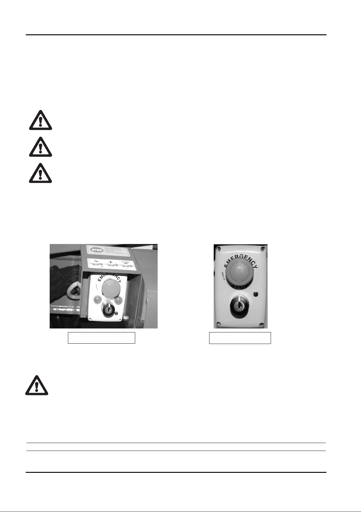
‑ EMERGENCY CONTROL POSITION
There is a control position that will be identified as the emergency control position. It is on
the part of the machine on the ground in correspondence with the aerial part distributor. To
enable, act on the relevant selector switch at the base of the turret (see photo) until the green
indicator switches on. This indicates movement enabling of the aerial part.
From here it is possible to make machine movements by acting directly on the levers present
on the various hydraulic distributor elements, aerial (see photo 1) and proportional areas
(aerial part see photo 2).
The emergency control position has been designed, to operate on the extendible structure
only for emergency manoeuvres by rescue staff on the ground, which must be trained and
have know‑how regarding the functioning of the machine and its safety devices, for main‑
tenance interventions and to perform checks before starting work.
It is prohibited to move the structure from the ground position, if someone is present in
the basket, unless it is an emergency situation (sudden indisposition of the operator, tech‑
BOOM LIFT MODELS X23J
JLG
10
X23JR0620113
ATTENTION
THERMIC MOTOR
LITHIUM MOTOR
ATTENZIONE
Page 15

11
nical breakdown).
There is a control position usable only for operations of ordinary and extraordinary mainte‑
nance operations, position placed next the machine near the electic components box.
At the back of the protection box of the circuit board an auxiliary connector is placed for the
connection of the optional second remote control (see picture).
To enable this position it is necessary to operate on the key selector placed on the base of the
turret and connect the optional second remote control to the machine.
Before proceeding with the connection read carefully paragraph regarding the use of the
optional second remote control.
This control position is usable only to carry out controls and maintenance on the machine.
Do not use this position to control the machine during normal working operations.
Note: it is absolutely forbidden to move the machine from this position if one ore more
operators are in the basket.
BOOM LIFT MODELS X23J
JLG
X23JR0620113
PHOTO 1
PHOTO 2
POSITION OF THE OPTIONAL SECOND
REMOTE CONTROL CONNECTOR
OPTIONAL SECOND REMOTE
CONTROL CONNECTOR
ATTENTION
ATTENZIONE
Page 16

2.1.2 MACHINE IDENTIFICATION PLATE
The manufacturer’s plate is located in the front of the machine, on the electric engine protec‑
tion sump.
The image is shown below.
BOOM LIFT MODELS X23J
JLG
12
X23JR0620113
Manufactured by
HINOWA S.p.A.
Via Fontana
200
37054 NOGARA (VR)
ITALY
kg
2x80
JLG Industries. Inc - McConnellsburg. PA - USA
Model
Serial number
Date of manufacture
G.V.W. (Dry)
MAXIMUM ALLOWABLE OPERATING INCLINATION
MAX
12.5
M/S
=+
MAX
12.5
M/S
120
1x80
kg
kg
1°
kg
kg
kg
40
40
kg
07041700
200
N400
N
Page 17

13
2.1.3 MACHINE CLEARANCE
Maximum length in running order with basket installed ................................6003 mm
Track width ..............................................................................................................990/1290 mm
Maximum height in running order ......................................................................1990 mm
Approach angle ......................................................................................................22°
Maximum stabilisation angle on individual axle ..............................................13°
Outriggers max. base side......................................................................................3983 mm
Note: standard version with double manned basket.
BOOM LIFT MODELS X23J
JLG
X23JR0620113
Page 18

2.1.4 TECHNICAL DATA
NB: The lateral reach is measured from the coupling attachment centre to the external edge
of the cage.
BOOM LIFT MODELS X23J
JLG
14
X23JR0620113
PLATFORM CAPACITY 200 kg 120 kg
PLATFORM HEIGHT (walkway surface) 19,70 m 21,10 m
MAX WORKING HEIGHT 21,80 m 23,20 m
STANDARD BASKET DIMENSIONS 1335 x 690 x H1100 mm
HORIZONTAL REACH (basket not rotated) 9,75 m 11,13 m
MAX. HORIZONTAL WORK REACH (basket not rotated) 10,25 m 11,63 m
ROTATION (non-continuous) 360° 360°
BASKET ROTATION 124° (+/- 62°)
MAX GROUND REACTION FORCE FOR EACH STABILISER 2100 daN
MAX GROUND PRESSURE FOR EACH STABILISER 3 daN/cm
2
NO. OF OPERATORS 2 1
JIB - TYPE OF ARTICULATED JOINT 85° (-1°/-86°)
MAX WORKING GRADIENT 1°/1,75%
MAX STABILISATION SLOPE 13°
TOTAL EMPTY MACHINE WEIGHT (Petrol vers.) 2990 kg
TOTAL EMPTY MACHINE WEIGHT (Diesel vers.) 3100 kg
ENGINE
HONDA iGX440-12,7CV-3600 rpm
PERKINS 402.05 -14CV-3600 rpm
ELECTRIC MOTOR
2.2 kw/230V/50Hz single phase 1500 rpm
2.2 kw/240V/50Hz single phase 1500 rpm
2.2 kw/110V/50Hz single phase 1500 rpm
ELECTRICAL SYSTEM VOLTAGE 12 V
PUMPS 2x4.27cc
MAX. TRAVERSING SPEED Autotwospeed 1,0 / 1,7 km/h (thermic motor)
MAX. TRAVERSING SPEED Autotwospeed 0,7 / 1,2 km/h (lithium motor)
TRAVEL/STAB. SYSTEM PRESSURE 160 bar
AERIAL PART SYSTEM PRESSURE 200 bar
MAX SLOPE ALLOWED IN TRAVEL DIRECTION 15°
MAX WIND SPEED 12,5 m/s
MAX MANUAL FORCE ALLOWED 400 N
Page 19

15
2.1.4.1 PETROL ENGINE TEHNICAL DATA
Mark/Model........................................................................HONDA iGX440
Fuel/Cooling ......................................................................PETROL/AIR
Power SAEJ1349 ................................................................9,5 kW (12,7 CV) / 3600 rpm
Maximum adjusted output rpm......................................3600 rpm
Maximum torque ..............................................................29,8 Nm/2500 rpm (80/1269/EC)
Number of cylinders..................................................................1
Displacement......................................................................440 cm
3
Cooling................................................................................air
Sound pressure level at operator’s ear ..........................88 dB
Measured sound power level ..........................................102 dB
Guaranteed sound power level ......................................104 dB
2.1.4.2 DIESEL ENGINE TECHNICAL DATA
Mark/Model........................................................................PERKINS 402.05
Fuel/Cooling ......................................................................DIESEL/LIQUID
Power SAEJ1349 ................................................................10,2 kW (14 CV) / 3600 rpm
Adjusted maximum speed rpm ......................................3500 rpm
Maximum torque ..............................................................29,7 Nm/2400 rpm (80/1269/EC)
Number of cylinders..................................................................2
Displacement......................................................................510 cm
3
Cooling................................................................................liquid
Sound pressure level at operator’s ear ..........................90 dB
Measured sound power level ..........................................102 dB
Guaranteed sound power level ......................................104 dB
2.1.4.3 HYDRAULIC SYSTEM TECHNICAL DATA
Hydraulic oil tank capacity..............................................48 liters
Engine pump......................................................................double 2x4,27cm
3
Hydraulic system max. pressure ....................................200 bar
For further information, refer to the hydraulic layout attached to the manual and the para‑
graph relative to maintenance of these components.
BOOM LIFT MODELS X23J
JLG
X23JR0620113
Page 20

2.1.4.4 ELECTRICAL SYSTEM TECHNICAL SPECIFICATIONS THERMIC
Battery ................................................................................55 Ah ‑ 417 A ‑ 12V
Alternator petrol engine ..................................................20 A (3600 rpm)
Alternator diesel engine ..................................................15 A (3600 rpm)
Electric engine: ‑ nominal voltage ..................................230V (110 V, 240 V optional)
‑ frequency............................................50 Hz (60 Hz optional)
‑ nominal power ..................................2,2 kW
For further information, refer to the wiring diagram attached to the manual and the para‑
graph relative to maintenance of these components.
2.1.4.5 ELECTRICAL SYSTEM TECHNICAL SPECIFICATIONS LITHIUM
Battery ................................................................................90 Ah ‑ 70V
Electric motor: ‑ rated voltage ..................................80 V
‑ rated power....................................3500 W
Sound pressure level at operator’s ear ..........................70 dB
Measured sound power level ..........................................86 dB
Guaranteed sound power level ......................................88 dB
Onboard battery charger .................................................. 220V±10V 50÷60Hz
Battery charger (option).................................................... 110V±10V 50÷60Hz
Max power absorbed by the battery charger during recharge phase: 3000W
For further information, see wiring diagram enclosed with the manual and the paragraph on
maintenance of electrical components.
BOOM LIFT MODELS X23J
JLG
16
X23JR0620113
Page 21

17
2.1.5 TERMINOLOGY
To make the content of this manual easier to understand, a layout is put at the reader’s
disposal that gives the exact terms with which the parts of the platform will be identified.
KEY
1 Tracked undercarriage
2 Emergency controls
3 Overhead part distributors
4 Swivelling turret
5 Coupling attachment + rotation motor
6 Diesel tank (only in diesel version)
7 Base
8 Track part distributors compartment
9 Oil tank
10 Outrigger joint
11 Geared double pump
12 Petrol/diesel engine
13 Jib return
14 Outrigger cylinder
15 Outrigger
16 First arm
17 First arm tie‑rod
18 First‑second arm cylinder
19 First‑second arm return
20 Jib arm
21 Jib return
BOOM LIFT MODELS X23J
JLG
X23JR0620113
THERMIC MOTOR
Page 22

22 Basket on basket levelling cylinder
23 Rotary actuator for basket rotation
24 Basket support
25 Basket access ladder
26 Basket
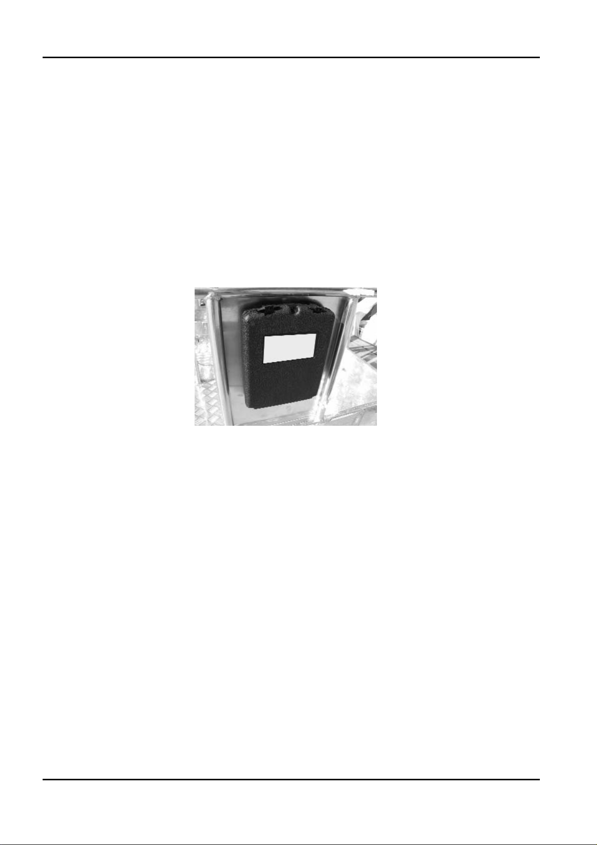
27 Use and maintenance manual compartment
28 Movement control remote control
29 Jib tie‑rod
30 Jib cylinder
31 Telescopic arm 2
32 Telescopic arm1
33 Third arm
34 Outrigger plate
35 Second ‑ third arm return
36 Basket levelling cylinder on connection
37 Third arm cylinder
38 Second arm
39 Second arm tie‑rod
40 Double pump with gears
41 Proportional valves compartment and hand pump
42 Electric components compartment
BOOM LIFT MODELS X23J
JLG
18
X23JR0620113
Page 23

19
KEY
1 Tracked undercarriage
2 Emergency controls
3 Overhead part distributors
4 Battery charge
5 Coupling attachment + rotation motor
6 Swiveling turret
7 Base
8 Track part distributors compartment
9 Oil tank
10 Outrigger joint
11 Geared double pump
12 Battery pack + inverter + battery charger (
LITHIUM MOTOR)
13 Electric motor
14 Outrigger cylinder
15 Outrigger
16 First arm
17 First arm tie‑rod
18 First‑second arm cylinder
19 First‑second arm return
20 Jib arm
21 Jib return
22 Basket on basket levelling cylinder
23 Rotary actuator for basket rotation
24 Basket support
25 Basket access ladder
BOOM LIFT MODELS X23J
JLG
X23JR0620113
LITHIUM MOTOR
Page 24

26 Basket
27 Use and maintenance manual compartment
28 Movement control remote control
29 Jib tie‑rod
30 Jib cylinder
31 Telescopic arm 2
32 Telescopic arm1
33 Third arm
34 Outrigger plate
35 Second ‑ third arm return
36 Basket levelling cylinder on connection
37 Third arm cylinder
38 Second arm
39 Second arm tie‑rod
40 Ignition key
41 Proportional valves compartment and hand pump
42 Electric components compartment + buffer battery
BOOM LIFT MODELS X23J
JLG
20
X23JR0620113
Page 25

21
2.1.6 TRANSPORT AND STABILISATION POSITION (STANDARD VERSION)
The overhead platform has rotating outriggers on a joint connecting the frame and outrigger
itself.
Regarding the outriggers, two positions are defined:
• TRANSPORT POSITION
• STABILISATION POSITION
The transport position is defined as the completely closed configuration and aligned with the
completely lifted and turned outriggers in a way to be parallel to the machine axle.
This configuration is the most compact possible for the machine and is that recommended for
all traversing operations on flat surfaces.
In the transport configuration, the vicinity of the outrig‑
ger plates to the basket handrail creates a potential
shearing hazard, it is appropriately indicated with
stickers.
Do not place the hands in this area during traversing
phases.
The stabilisation position is defined as that with the
outriggers raised from the ground, but turned by
about 45° with respect to the machine axis in a way
to almost create a square with the outrigger plates
positioned on the ends.
A lock pin with spring positioning blocks the outrig‑
gers in one or other position.
For the stabilization positions of the version with variable stabilization area please read
paragraph 6.4.6 Passage from transport configuration to stabilisation configuration Stan‑
dard version.
BOOM LIFT MODELS X23J
JLG
X23JR0620113
IMPORTANT
IMPORTANTE
Page 26

2.2 GENERAL SAFETY STANDARDS
The functioning of the MEWP must be in compliance with international standards of referen‑
ce (see paragraph “NORMATIVE REFERENCES” in the first pages of the manual) and natio‑
nal or regional standards if stricter.
The operator must read, understand and follow all the instructions and warnings, contained
in this manual and on the machine, regarding the safe use of the MEWP.
FAILURE TO COMPLY WITH THE SAFETY PRECAUTIONS LISTED IN THIS SECTION
AND STATED ON THE MACHINE CAN CAUSE INJURY OR DEATH OF THE STAFF AND
DAMAGE TO THE MACHINE AND CONSTITUTES A SERIOUS INFRACTION OF THE
SAFETY STANDARDS.
This section of the USE AND MAINTENANCE MANUAL describes those procedures or
dangerous situations that can cause damage/injury to objects/persons and what the operator
must do to prevent them.
• The operator must always act as a professional, complying with safety standards, paying
attention not to under‑estimate his responsibility to himself and all objects and persons that
surround him.
• Before starting work it is indispensable that the operator has been completely and
clearly trained regarding the use of the machine in standard and emergency conditions.
That he has examined, understood and taken in all that stated in this user manual. That he
is sure that the safety devices are in perfect working order, that the necessary checks on
the machine are performed and that he becomes familiar with the conditions of the
ground on which he must manoeuvre and stabilise.
• The presence of at least one specialised person is necessary on the ground during working.
This person must know how to use the machine and be aware of the content of the USE AND
MAINTENANCE MANUAL and can intervene if necessary.
• It is prohibited to make modifications to the machine that could jeopardise functioning and
safety, without previous written authorisation from The Constructor which is not liable for
any injury or damage caused by this behaviour.
Protection devices and garments
Do not wear loose clothing, rings, watches or anything else
that may become entangled in moving parts.
When using the machine or performing maintenance wear a
hard helmet, goggles and accident‑prevention shoes, gloves
and hearing protection after having checked their integrity
along with any other IPD that the safety manager deems
necessary according to the risk analysis he has performed.
BOOM LIFT MODELS X23J
JLG
22
X23JR0620113
ATTENZIONE
WARNING
Page 27

23
ALWAYS WEAR TYPE‑APPROVED AND CERTIFIED THE SLINGING. WHEN WORKING AT A HEIGHT MAKE
SURE YOU ARE WEARING THE SAFETY BELTS CORRECTLY AND THEY HAVE BEEN APPROPRIATELY ATTA
‑
CHED TO THE RELEVANT ANCHORAGE POINTS ON THE BASKET.
T
HE USE OF THE SLINGINGS IS COMPULSORY IN CONNECTION WITH THE LOCAL REGULATINS OF
EVERY SINGLE
STAT E. IN THOSE STATES WHERE THE LAW DOES NOT REQUIRE THE USE OF HOLDING
SYSTEMS
, THE CHOICE IS OF THE EMPLOYER OR/AND USER
Safety valves and safety components of the electric system
It is prohibited to modify and/or tamper with the safety and control valves of the main
hydraulic system and the adjustments of the electric plant. The Constructor is not liable
for injury to persons and damage to objects or to the machine if the standard calibration
of any hydraulic and electric/electronic component is tampered with.
Fire prevention
Keep the area around the engine clean, removing fragments of
wood, paper and other inflammable products; clean any fuel
leaks as they can be a potential cause of fire.
Petrol is extremely inflammable and explosive in particular
conditions. Re‑fuel in a well‑aired place with the engine at a
standstill.
Do not smoke or make sparks in the re‑fuel area or fuel stora‑
ge area.
After having re‑fuelled, make sure the cap is closed securely.
Do not touch the exhaust when hot during machine functioning or immediately after the
engine is switched off.
Prevention of damage caused by washing the machine
Do not aim high pressure jets onto electric components when
washing the machine. Do not use chemical detergents or
petrol that could cause serious damage to plastic components
and the paintwork.
A
LWAYS REMEMBER TO REMOVE THE REMOTE CONTROL AND COR‑
RECTLY CLOSE THE REMOTE CONTROL CONNECTION SOCKETS AND
EQUIPMENT POSITIONED ON THE MACHINE
, BEFORE WASHING.
BOOM LIFT MODELS X23J
JLG
X23JR0620113
IMPORTANT
IMPORTANTE
Page 28

• Cleaning the machine
Always park the machine as shown in the figure in point 2.1.6.
When washing the machine, the ignition block must be disengaged, the key removed and the
emergency stop button pressed.
• Washing the outside of the machine
Never use flammable liquids. Adopt the above safety measures to
prevent sparks due to short‑circuits.
If washing the track with water cleaners, carefully protect all the
important parts and above all the electrical components. Follow the
instructions provided by the manufacturer of the detergent.
Clean the machine using water‑soluble detergents.
The more the elevating platform is cleaned, the more it will need to be greased (see par.
Grease points).
Do not wet the electric motors and the other electrical components directly. Do not aim the
spray directly onto adhesive labels and rating plates.
• Cleaning the electrical system
Never clean the inverter or the electric motor with water, as this may
cause damage to the electrical system.
BOOM LIFT MODELS X23J
JLG
24
X23JR0620113
ATTENZIONE
ATTENZIONE
ATTENTION
ATTENTION
ATTENTION
ATTENTION
ATTENZIONE
ATTENZIONE
Page 29

25
Only use dry detergents, in accordance with the manufacturer’s instructions. Never remove
covers, guards and the like.
‑ Clean the electrical system using a dry, non‑metallic brush and low pressure air.
• After cleaning
Dry the machine carefully before starting it again (for example using compressed air).
If, despite all the precautions, moisture has penetrated into the electric motor or other parts
of the electric system, these must be dried using compressed air to avoid the risk of short‑cir‑
cuits.
Prevention of damage caused by the working machine
When the machine is stabilised and work started, do not enter its radius of action.
Systematically manoeuvre the controls slowly and regularly, do not reverse movements
abruptly.
During work operations outside of the basket, ALWAYS remain at a MINIMUM DISTANCE
OF 1 METER from the machine.
BOOM LIFT MODELS X23J
JLG
X23JR0620113
IMPORTANTE
IMPORTANT
ATTENTION
ATTENZIONE
Page 30

2.3 SAFETY WARNINGS
2.3.1 GENERALITIES
To prevent accidents, before starting work or carrying out any
maintenance, read, understand and follow all precautions and
warnings contained in this manual. The user / operator of the
machine must refuse all operating responsibility until this
manual has been read and he has learned to manoeuvre the
machine completely under the surveillance of a skilled and qua‑
lified operator.
Carefully read all safety messages in this manual along with the safety signs on your machi‑
ne.
Keep the safety signs in a good state and replace them if they are damaged.
Make sure that any new machine components have the correct safety signs.
2.3.2 NOISE AND VIBRATIONS
The JLG platforms with engine have been tested according to the parameters of the 2000/14
CE European Standard, having a guaranteed sound power level detected, stated in the
machines EC Declaration of Conformity.
During the use of machines for aerial operations this value is further reduced due to the
moving away of the basket from the main source of noise.
The values of the vibrations transmitted to the operator via the controls and directly from the
surface of the basket resulted less than the maximum accepted limits.
BOOM LIFT MODELS X23J
JLG
26
X23JR0620113
Page 31

27
2.3.3 PICTOGRAMS POSITIONED ON THE MACHINE
Here we report the positions of the various boards with pictograms on the machine.
BOOM LIFT MODELS X23J
JLG
X23JR0620113
26
57
63
73
17
27
83
72
19
75
73
28
47 75
18
28
26 8 10
27
32
59
82
58
33
20
54
28 76 80 28
25
19
30
18
75
77
48
26
83
81
44
79
49
11
11
Ed. 06/12/2012 Tav 01
Cod. 17062700
ADHESIEKIT - X23J
28 39 47 41 1 28 39 47 41 39
47
39
28
11
18
10
25
20
4
25 31 14
70
18
30 19 53
50
51
24
60
64
11
12
67
23
KIT ADESIVI - X23J AUFKLEBERSATZ - X23J
SET OF DECALS - X23J KIT ADHESIVOS - X23J
KIT COLLANTS - X23J
Page 32

BOOM LIFT MODELS X23J
JLG
28
X23JR0620113
47 39 28
18
21
73
75
v
v
84
10
28
11
v
v
74
v
v
25
20
v
v
v
v
30 18 19 55 73
29
v
Ed. 06/12/2012 Tav 02
v
v
35
v
v
70
v
Cod. 17062700
47
28 47 39 1 41 39
41
18
28 28 47 39
66
75
8
75
26
10
4 25 31 14
56 19 30 18
20
25
27
37
v
v
40
v
12
24
45
v
v
38
23
60
v
v
v
v
v
v
11
64
KIT ADESIVI - X23J AUFKLEBERSATZ - X23J
SET OF DECALS - X23J KIT ADHESIVOS - X23J
ADHESIEKIT - X23J
KIT COLLANTS - X23J
Page 33

29
BOOM LIFT MODELS X23J
JLG
X23JR0620113
Pos. Code qty
01 07060700 02
02
03
04 07060500 02
05
06
07
08 07061300 02
09
10 1646410008 04
11 06040300 06
12 1704277 02
13
14 1646410007 02
15
16
17
18 06039900 12
19 06039700 09
20 06039600 04
21 06527700 01
22
23
24
25 06041200 06
26
27 06040900 03
28 06041300 12
29 06056300 01
30 06044000 08
31 06040500 02
32 1702155 01
33 1701542 01
33 1701505 01
34
35 06598400 01
36
37 1701504 01
38 06165000 01
39 1703814 08
40 07034200 01
41 07056700 04
42
43
44 1646410010 01
45
46
Pos. Code qty
47 1701499 08
48 06086000 01
49 06085900 01
50 1646410013 01
51 1646410012 01
52
53 06555500 01
54 06555600 01
55 06555700 01
56 06555800 01
57 06560500 01
58 06232100 01
59 06060000 01
60 06040000 02
61
62
63 06600000 01
64 06086700 02
65
66
67 06706500 01
68
69
70 07056800 02
71
72 07060000 01
73 07060400 04
74 1646410006 01
75 1001125483 06
76 06924300 01
77 06919400 01
78
79 1706898 01
80 1706493 01
81 1705828 01
82 1706098 01
83 07050700 02
84 07071000 01
Page 34

LANGUAGE STICKERS
BOOM LIFT MODELS X23J
JLG
30
X23JR0620113
Pos. Code qty
170627IT
17 06555300 01
23 06448100 02
24 06448200 02
26 06561200 04
45 07203200 01
66 07070200 01
170627GB
17 06562600 01
23 06462100 02
24 06462700 02
26 06561200 04
26 06042400 04
45 07206200 01
66 07042300 01
170627FR
17 06562700 01
23 06462200 02
24 06462800 02
26 06561200 04
45 07206300 01
66 07070300 01
170627DE
17 06562800 01
23 06462300 02
24 06462900 02
26 06561200 04
45 07206400 01
66 07070400 01
170627ES
17 06562900 01
23 06462400 02
24 06463000 02
26 06561200 04
45 07206500 01
66 07070500 01
Pos. Code qty
170627NL
17 06563000 01
23 06462500 02
24 06463100 02
26 06561200 04
45 07206600 01
66 07070600 01
170627PT
17 06563100 01
23 06462600 02
24 06463200 02
26 06561200 04
45 07206700 01
66 07070700 01
170627DA
17 07138100 01
23 07137900 02
24 07138000 02
26 06561200 04
45 07206800 01
66 07138200 01
170627SW
17 07137300 01
23 07137400 02
24 07137500 02
26 06561200 04
45 07206900 01
66 07148800 01
170627NO
17 07162000 01
23 07161900 02
24 07161800 02
26 06561200 04
45 07207000 01
66 07162100 01
Page 35

31
BOOM LIFT MODELS X23J
JLG
X23JR0620113
9
Ed. 31/10/2012 Tav 01
cod. 17187700
4
5
13
KIT ADESIVI - X23J AUFKLEBERSATZ - X23J
SET OF DECALS - X23J KIT ADHESIVOS - X23J
ADHESIEKIT - X23J
KIT COLLANTS - X23J
Page 36

BOOM LIFT MODELS X23J
JLG
32
X23JR0620113
4
18
Sotto il carter / Under the hood
18
16
Ed. 31/10/2012 Tav 02
cod. 17187700
9
4
ADHESIEKIT - X23J
1
KIT ADESIVI - X23J AUFKLEBERSATZ - X23J
SET OF DECALS - X23J K IT ADHESIVOS - X23J
KIT COLLANTS - X23J
Page 37

33
LANGUAGE STICKERS
BOOM LIFT MODELS X23J
JLG
X23JR0620113
Pos Code
qty
1
2
3
4 1001125483 3
5 06506400 1
9 06520600 2
18 07264800 2
Pos Code
qty
171877IT
1 07188700 1
7
10
11
12
13 07188100 1
14
16 1693870003 1
16 1705720001 1
Pos Code
qty
171877GB
1 07201700 1
7
10
11
12
13 07202100 1
14
16 1693870004 1
16 1705720002 1
Pos Code
qty
171788FR
1 07201800 1
7
10
11
12
13 07202200 1
14
16 1693870005 1
16 1705720003 1
Pos Code
qty
171877DE
1 07188800 1
7
10
11
12
13 07188200 1
14
16 1693870006 1
16 1705720004 1
Page 38

BOOM LIFT MODELS X23J
JLG
34
X23JR0620113
Pos Code
qty
171877ES
1 07201900 1
7
10
11
12
13 07202300 1
14
16 1693870007 1
16 1705720005 1
Pos Code
qty
171877NL
1 07188900 1
7
10
11
12
13 07188300 1
14
16 1693870008 1
16 1705720006 1
Pos Code
qty
171877PT
1 07202000 1
7
10
11
12
13 07202400 1
14
16 1693870009 1
16 1705720007 1
Pos Code
qty
171877SW
1 07189000 1
7
10
11
12
13 07188400 1
14
16 1693870010 1
16 1705720010 1
Pos Code
qty
171877DA
1 07189100 1
7
10
11
12
13 07188500 1
14
16 1693870011 1
16 1705720011 1
Pos Code
qty
171877NO
1 07189200 1
7
10
11
12
13 07188600 1
14
16 1693870012 1
16 1705720012 1
Page 39

35
BOOM LIFT MODELS X23J
JLG
X23JR0620113
Code Name Description Identikit
06040300
WARNING KEEP
SAFE DISTANCE
06040500
SENSE OF MOVING
UNDERCARRIAGE
DEFINED AS THE
DIRECTION FORWARD
06040800
CRUSHING HAZARD
PERSON
06040900
OBLIGATION TO
READ THE MANUAL
BEFORE USE OF
MACHINE
1703814
FIXING POINT FOR
TRANSPORT
INDICATES CORRECT
FIXING POINT FOR
TRANSPORT OF THE
MACHINE
06041200
CRUSHING HAZARD
FEET
INDICATES AREAS
WHERE THERE IS A
DANGER OF CRU‑
SHING LOWER LIMBS
FOR THE OPERATOR
06041300
CRUSHING HAZARD
PERSON
INDICATES AREAS
WHERE THERE IS A
DANGER OF CRU‑
SHING UPPER LIMBS
FOR THE OPERATOR
06040300
06040500
06040800
06040900
1703814A
06041200
06041300
Page 40

BOOM LIFT MODELS X23J
JLG
36
X23JR0620113
Code Name Description Identikit
06044000 LIFTING POINT
INDICATES CORRECT
LIFTING POINTS FOR
LIFT THE MACHINE
06056300
DANGER HIGHT
TEMPERATURE
06060000 ENGINE OIL LEVEL
06085900
EMERGENCY DEVI‑
CE FOR AERIAL
PART
DEVICE THAT ALLOWS
TO EXCLUDE THE
SAFETY OF THE
AEREAL PART IN CASE
OF EMERGENCY OPE‑
RATIONS
06086000
EMERGENCY DEVI‑
CE FOR UNDERCAR‑
RIAGE
DEVICE THAT ALLOWS
TO EXCLUDE THE
SAFETY OF THE
UNDERCARRIAGE IN
CASE OF EMERGENCY
OPERATIONS
06086600
WARNING KEEP
SAFE DISTANCE
AND CRUSHING
HAZARD PERSON
0
6
0
4
4
0
0
0
06056300
0
0
0
0
6
0
6
0
06085900
06086000
06086600
Page 41

37
BOOM LIFT MODELS X23J
JLG
X23JR0620113
Code Name Description Identikit
06165000
HYDRAULIC OIL
LEVEL
1701499
FORBIDDEN LIFTING
POINT
1001125483
DO NOT WASH WITH
WATER
06560500 GROUNDING
06598400
HAND PUMP
LEGEND
QUICK INSTRUCTIONS
FOR USING THE EMER‑
GENCY HAND PUMP
06924300
BE CAREFULL AT
WORK
USING SAFETY HAR‑
NESSES, USE PROTECTI‑
VE EQUIPMENT (HEL‑
MET), PROHIBITION OF
WELD ON THE MACHI‑
NE, PROHIBITION OF
USE SYSTEMS TO
INCREASE THE AREA
OF WORK INSIDE THE
BASKET , PROHIBITION
OF WORKING IN THE
VICINITY OF VOLTAGE
ELECTRIC, PROHIBI‑
TION OF USE OF THE
PLATFORM FOR RAI‑
SING LOADS
1701499
1001125483
06560500
0
0
0
5
6
1
6
0
06598400
0692430006924300
Page 42

REPLACE STICKERS AND PLATES AS SOON AS THEY DETERIORATE.
THE FAILURE TO COMPLY WITH ANY PRESCRIPTION DUE TO DETERIORA‑
TION, LOSS, OR NON‑CONSULTATION OF A SAFETY STICKER, CAN BE THE
CAUSE OF SERIOUS ACCIDENTS.
BOOM LIFT MODELS X23J
JLG
38
X23JR0620113
Code Name Description Identikit
07107200
BATTERY PACK
WARNINGS
CORROSIVE LIQUID
Presence of highly corro‑
sive liquid, dangerous to
the body and eyes.
HIGH VOLTAGE
Presence of high voltage
with danger of electric
shock.
DANGER OF EXPLO‑
SION
Formation of potentially
explosive mixture inside
the battery.
NO NAKED FLAMES
Do not smoke or use
naked flames when
recharging and near the
vehicle. Risk of explo‑
sion.
RECYCLING
It is highly recommended
to comply with legislati‑
ve and environmental
standards as regards the
demolition, reuse, recy‑
cling and recovery of
materials.
Page 43

39
BOOM LIFT MODELS X23J
JLG
X23JR0620113
Page 44

3 SAFETY DEVICES
The notions stated below concerning the safety devices are made available to the user in
order to understand machine behaviour and possible work sequences; moreover, in this way
it is possible to identify any breakdowns with greater certainty in order to supply more
detailed information to the after‑sales service for quicker, less expensive interventions.
The machine is equipped with safety devices used to prevent dangerous situations for the
operator from occurring. It is important that before starting any operation, the operator
checks the perfect working order of these devices.
The non‑functioning of a safety device, whether caused by a fault or tampering, can cause
serious damage to the machine and consequently put the operator’s life at risk. The Con‑
structor has designed the machine and safety devices in order to guarantee the maximum to
its customers, however the devices must be checked periodically according to that described
in this manual and they must never be tampered with.
The service function on the remote control can be used as an aid for checking electric safety
devices.
Never intervene on the safety devices. If they are tampered with the manufacturer declines
all liability regarding any accidents that can be blamed on these interventions.
It is prohibited to tamper with the lead sealing or calibration of the maximum pressure val‑
ves and the adjustments of the electric components. If they are tampered with the manufac‑
turer declines liability for any accidents that can be blamed on these interventions.
The Constructor is not liable for any damage/injury caused by the machine to objects and/or
persons due to failure to comply of that stated above.
BOOM LIFT MODELS X23J
JLG
40
X23JR0620113
Page 45
41
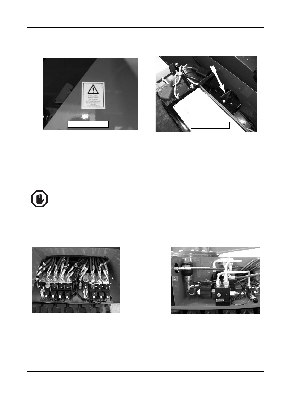
3.1 BATTERY CUT‑OUT
This device, positioned on the left side of the electric components box allows to cut‑off the machine
electric circuit, blocking any movement. It is well‑visible and easily accessed without the use of
tools. It has to be activated only in case of prolonged machine down time or maintenance
assistance.
By turning the key in a clockwise direction the machine’s electric circuit is closed, while tur‑
ning it in an anti‑clockwise direction the machine’s electric circuit is cut‑off and the key can
be removed.
B
EFORE DISCONNECTING THE BATTERY THROUGH THIS DEVICE, MAKE SURE THAT THE ENGINE KEY IS
IN
OFF POSITION, AND THE REMOTE CONTROL AND ELECTRIC BOARD ARE COMPLETELY TURNED OFF.
3.2 D
ISTRIBUTORS OVER‑PRESSURE VALVES
All platform distributors have an over‑pressure valve that limits the pressure that can be rea‑
ched inside the calibration pressure plant of the valve itself.
These valves are calibrated in the platform inspection phase by qualified staff working and
must not be tampered with for any reason.
BOOM LIFT MODELS X23J
JLG
X23JR0620113
IMPORTANT
THERMIC MOTOR
LITHIUM MOTOR
IMPORTANTE
Page 46

3.3 CYLINDER CUT‑OFF VALVES
The outrigger cylinders have a double cut‑off valve, which in case of plant breakdown or
pipe breakage, cut‑off the cylinder preventing dangerous platform instability situations. All
cylinders that move the aerial part of the platform structure are equipped with a cut‑off
valve, which in case of plant breakdown or pipe breakage cut‑off the cylinder preventing the
basket falling due to gravity.
These valves are calibrated in the platform inspection phase by qualified staff working
and must not be tampered with for any reason.
3.4 A
ERIAL PART ALIGNMENT PHOTOCELLS OF THE STRUCTURE AND MACHINE BASE
The platform has two reflection safety photocells that check that the aerial part of the machi‑
ne structure is completely lowered and aligned with the base and that the telescopic arm is
completely retracted.
When these conditions do not occur, a signal is given that disables outrigger movement.
BOOM LIFT MODELS X23J
JLG
42
X23JR0620113
Page 47

43
3.5 OUTRIGGERS POSITION MICRO SWITCHES STANDARD VERSION
The position of the outriggers and their contact with the ground is detected by 4 pairs of
micro switches positioned in proximity of the outriggers orientation joints and the outrigger
cylinder rod fixing pin.
SEE PHOTO
The micro switches positioned on the joints must be released when the outrigger is in the sta‑
bilisation position (about 58° with respect to machine axis)and pressed when the outrigger is
in the remaining positions until it reaches the transport position parallel to the machine axis.
The micro switches fixed onto the outrigger must be released when the outrigger rests on the
ground. Control the correct functioning of the micro‑switches daily.
VERSION WITH VARIABLE STABILIZATION AREA
The machines with variable sabilization area, in addition to the
above described, are equippeed with four microswitches which con‑
trol the position of the outriggers, total or reduced area, and based
on this allow or limit the rotation of the aerial part of the machine.
They are also equipped with a sensor which controls the angular
position of the aerial part compared to the the undercarriage part of
the machine.
The checking of the correct functioning of the four microswitches
is compulsory before every stabilization of the machine, in order
to do this operation position one outrigger in reduced stabilization
area and the other three in total area and check that on the remote
control appears the reduced area icon, repeat this operation for
every outrigger.
Check the correct positioning of the microswitches at every use, as indicated on the decal
positioned on the machine.
BOOM LIFT MODELS X23J
JLG
X23JR0620113
Page 48

BOOM LIFT MODELS X23J
JLG
44
X23JR0620113
POSM
POS
POSM
POS
PRIMA DI OGNI UTILIZZO VERIFICARE IL CORRETTO
FUNZIONAMENTO E FISSAGGIO DEI MICROINTERRUTTORI
BEFORE EVERY USE CHECK THE CORRECT FUNCTIONING AND
FASTENING OF THE MICROSWITCHES
AVANT DE CHAQUE EMPLOI, VERIFIER LE CORRECT
FONCTIONNEMENT ET FIXAGE DES MICROINTERRUPTEURS
VOR JEDER INBETRIEBNAHME DAS KORREKTE FUNKTIONIEREN UND
DIE BEFESTIGUNG DER MIKROSCHALTER ÜBERPRÜFEN
ANTES DE CADA
FUNCIONAMIENTO Y FIJACION DE LOS MICROINTERRUPTORES
VOOR GEBRUIK DIENT U HET FUNCTIONEREN EN DE SNELHEID VAN
DE MICROSCHAKELAARS TE CONTROLEREN
ANTES DE
FUNCIONAMENTO E FIXAÇÃO DOS MICRO-INTERRUPTORES
STABILIZZATORE IN AREA TOTALE SPIA ACCESA
OUTRIGGER IN TOTAL AREA WARNING LIGHT ON
STABILISATEUR DANS SUFACE TOTALE VOYANT ALLUMÉ
STABILISATOR AUF GESAMTER FLÄCHE WARNLICHT AN
ESTABILIZADORES EN AREA TOTAL LUZ PERMANENTE
BIJ MAXIMALE UITSTEMPELING BRANDT HET
WAARSCHUWINGSLICHT
ESTABILIZADOR EM ÁREA TOTAL LUZ INDICADORA ACENDIDA
STABILIZZATORE IN AREA RIDOTTA SPIA INTERMITTENTE
OUTRIGGER IN REDUCED AREA INTERMITTENT WARNING LIGHT
STABILISATEUR DANS SUR
STABILISATOR AUF BEGRENZTER FLÄCHE WARNLICHT BLINKEND
ESTABILIZADORES EN AREA REDUCIDA LUZ INTERMITENTE
BIJ GEDEELTELIJKE UITSTEMPELING KNIPPERT HET
WAARSCHUWINGSLICHT
ESTABILIZADOR EM ÁREA REDUZIDA LUZ INDICADORA INTERMITENTE
UTILIZACION VERIFICAR EL CORRECTO
CADA UMA UTILIZAÇÃO VERIFICAR O CORRECTO
FACE REDUITE VOYANT INTERMITTENT
07060400A
POSM
POS
STABILIZZATORE CHIUSO
CLOSED OUTRIGGER
STABILISATEUR FERMÉ
GESCHLOSSENER STABILISATOR
ESTABILIZADOR CERRADO
ONTROLEER HET FUNCTIONEREN VAN DE MICROSCHAKELAARS
ESTABILIZADOR FECHADO
Page 49

45
3.6 JIB POSITION MICRO SWITCH
The position of the Jib is detected by a micro switch fixed
onto the jib arm itself and it works in a slot made in the
JIB transmission.
The micro switch must be released when the Jib arm is
closed.
Control daily the status and correct functioning of the MICRO JIB.
3.7 R
OPES INTEGRITY MICRO SWITCH
The integrity of the ropes system that moves the telescopic arm is verified by a micro switch
that detects the position of the rope pull balancing system.
When both ropes are integral, the balancing system is parallel to the machine axle and the
micro switch must be released.
If the micro switch is not released due to an anomaly on one of the two ropes, a warning
message appears on the remote control display.
3.8 B
ASKET LOAD SENSOR
The load sensor present on the basket is made up from a
basket support with two shafts that only allow vertical
basket movement. The basket support is supplied by the
load cell itself. Two strain gauges are positioned inside the
sensor positioned under the basket, which change over
the relative weight inside the basket to an electric signal.
The electric signal is then sent to the circuit board that ela‑
borates it and identifies any dangerous conditions.
The max load depends on the working mode, if the
BOOM LIFT MODELS X23J
JLG
X23JR0620113
Page 50

machine works with jib open this load is 120 kg. If working with jib closed, the maximum
accepted load is 200 kg.
The indication of the max load based on the working mode is always displayed on the remo‑
te control.
When the maximum accepted load is reached, an icon appears on the remote control display
along with an acoustic signal and all platform movements are prevented. To restore platform
functioning the excess weight must be removed in order to drop below the maximum weight
accepted. (see paragraph regarding the display visualizations ).
The Constructor recommends that maximum attention is paid to
the state of all safety components and in particular to the system
that makes up the basket load sensor; always check correct func‑
tioning whenever objects are struck with the basket or if jobs are
being carried out that can damage the system (e.g. pruning,
painting etc.).
Before ascending, always make sure that the two lids of the vertical pins are COMPLE‑
TELY fastened into their seat.
3.9 C
ONTROL PROTECTIONS
The remote control is protected against the accidental fall
of objects from above and involuntary activation by the
operator by a protection structure.
Always check integrity before using the machine.
3.10 S
PIRIT LEVEL
The spirit level is positioned on the turret where it can be well
seen from the basket and from the ground. The spirit level must
be used to check that during the platform levelling phase the
maximum accepted inclination limit of 1° is respected. For this
to take place, the air bubble must never go out of the green area.
A second electronic spirit level, contained in the control board,
checks that this condition is effectively satisfied and checks the power supply of the controls
relative to the aerial part.
BOOM LIFT MODELS X23J
JLG
46
X23JR0620113
ATTENTION
DANGER
LID
ATTENZIONE
PERICOLO
Page 51

47
Control always the correct levelling of the machine after every self‑levelling operation.
Approximate levelling outside of the limits set by the manufacturer is very dangerous and
can jeopardise the stability of the platform creating sources of risk or even death for the ope‑
rator and other persons that operate in proximity of and on the machine.
Never intervene on the spirit level adjustments; this device is calibrated by the Constructor
during the inspection before sale. Only technicians authorised by the Constructor and in pos‑
session of suitable tools can intervene on the spirit level.
3.11 S
CREWS AND NUTS LOCKING PINS
All pins used on the JLG platform have been treated against wear and have a flange to pre‑
vent rotation within the seat.
The following safety parts are identified in each individual pin:
1‑ A
NTI‑ROTATION WING: always check integrity and no relative wing‑pin rotation.
BOOM LIFT MODELS X23J
JLG
X23JR0620113
2
3
4
1
Page 52

2‑ WING‑PIN FIXING LOCKNUT:
always check the coupling torque, which must be equal to 78 Nm.
3‑ L
OCKNUT ON END OF PIN TO PREVENT AXIAL SHIFTING:
always check the coupling torque, which must be equal to 25 Nm.
4‑ W
ING‑FRAME FIXING SCREWS:
always check the coupling torque, which must be equal to 29 Nm.
BOOM LIFT MODELS X23J
JLG
48
X23JR0620113
Page 53

49
Never loosen the pin locks, periodically check correct tightness. The escape, even partial,
of a pin from its seat could cause unexpected and uncontrollable movements and also the
loss of stability of the machine and/or cause the basket to fall.
3.12 S
AFETY DEVICE CONTROL CIRCUIT BOARD STANDARD VERSION
The JLG platform has a control circuit board (see photo)
that enables the power supply of the
ON‑OFF proportional
coils after verification of the safety conditions by means of
the sensors positioned on the machine.
The control functioning on the circuit board can be by‑pas‑
sed by means of the key selector switch with spring return:
“safety device by‑pass key”.
The circuit board records every by‑pass action of the safety
devices by the operator, cataloguing them by date, time and
duration for which the operator has held the “safety device
by‑pass key” in position.
The board also records events that memorises all operations performed on the machine for a
variable period of time.
REDUCED STABILIZATION AREA
This type of machine is equipped with an additional electronic control board (see picture)
which analyzing the position of the outriggers and of the aerial part discerns the permitted
rotation area.
All the functions of the electronic board previously described for the standard version are
unchanged.
BOOM LIFT MODELS X23J
JLG
X23JR0620113
Page 54

3.13 OUTRIGGER JOINT LOCK PINS
The outrigger joints have locking pins with spring return.
The pins enter their seats pushed by the force of the spring
both in the transport and stabilisation position.
Check positioning of the pins in their seat and the force of
the spring after every rotation of the outrigger.
3.14 A
RMS POSITION SENSORS
The cylinders of the 1st‑2nd arm and that of the 3rd arm are equipped with an internal posi‑
tion sensor that allows the circuit board to know the position of the cylinders and adjust the
speed.
The electric connection of the sensors is visible on the bottom of the cylinders.
When one of the two sensors is broken or its signal no longer reaches the main circuit board
an icon appears in position 7 of the remote control. (paragraph 4.2.1 display main visualiza‑
tion).
If the first arm sensor is broken, the machine will continue to work. If the third arm sensor is
broken, the aerial part will block.
If one or both sensors should break, contact the JLG after‑sales service.
BOOM LIFT MODELS X23J
JLG
50
X23JR0620113
Page 55

51
BOOM LIFT MODELS X23J
JLG
X23JR0620113
4 INSTRUMENTS AND CONTROLS
Successively find the indications of all controls and indicators present on the platform; each
device has a sticker that briefly describes the function applied in the close vicinity, but they
are often symbols used to favour quick and safe use. Before using the platform the following
descriptions must be read in order to have a more in‑depth knowledge of the functions of
each device and to be aware of any suggestions by the manufacturer.
Before starting to use the platform the operator must have read and perfectly understood the
provisions contained in the entire manual.
4.1 R
EMOTE CONTROL
The remote control has most of the machine controls for routine functioning.
The remote control is made up from buttons, Joysticks, key selector switches, displays.
The remote control has continuous exchange of data with the main board of the machine,
which sends the information to be viewed onto the display.
07071000B
56
Page 56

4.1.1 Display
The display is used to view the status of the machine and the operational information neces‑
sary or useful to the operator for use.
When the machine main control board is powered through the engine key, the information to
be seen on the display is sent to the remote control.
This operation has variable duration. Normally a few seconds are enough, but the following
screen may appear on the display:
In this case about 5‑10 minutes will be required to send all of the information from the main
board to the remote control. The machine does not function during this period.
Do not turn off the machine or operate on it during this period.
4.1.1.1 Display main screen
On switch on, the main screen will appear, which will give a general idea of the machine sta‑
tus. For simplicity and clarity a layout is created in which 8 icon display positions are identi‑
fied.
Example of main screen: Icon position layout:
BOOM LIFT MODELS X23J
JLG
52
X23JR0620113
Page 57

53
BOOM LIFT MODELS X23J
JLG
X23JR0620113
POSITION 1:
Position no. 1 relates the icon of reduced area in case the machine is stabilized in this confi‑
guration.
POSITION 2:
Position no. 2 displays the max weight based on the working mode: 120kg / 200kg
POSITION 3:
Position 3 displays the selected engine and the engine status.
Petrol/diesel engine Electric engine
An X present on the icon indicates that the engine is off; no X indicates that the engine is on.
POSITION 4:
Position 4 displays the selected speed or the reduced speed for the Lithium:
SLOW NORMAL FAST REDUCED
Page 58

POSITION 5:
Position 5 displays the icon for enabling the use of overhead movements.
The presence of the icon means that all conditions for use of the aerial movements have been
verified and it is possible to ascend. No icon indicates the impossibility to ascend.
Alternatively to this icon, the basket overload icon may appear.
When the load sensor detects a load exceeding the selected work load admitted ‑
120kg/200kg‑, the main screen disappears for three seconds, replaced by the overload error
display, the acoustic warning is activated, then the overload icon appears in position 5 in
place of the enabling icon for aerial movements.
OVERLOAD ERROR DISPLAY
BOOM LIFT MODELS X23J
JLG
54
X23JR0620113
Page 59

55
BOOM LIFT MODELS X23J
JLG
X23JR0620113
POSITION 6:
Position 6 displays the enabling icon for the use of track movements (outriggers, travels,
track widening).
The presence of the icon means that all conditions have been verified for the use of track
movements. No icon indicates the impossibility to move the outriggers and widening. Travel
movement can however take place without the presence of the icon as long as all 4 outrig‑
gers are lifted from the ground.
POSITION 7:
Position 7 is used for functional signals:
Emergency STOP pressed
Remember that one of the machine emergency stops is not released.
PRESS THE PEDAL BUTTON
BATTERY VOLTAGE LOWER THAN MINIMUM LIMIT.
Indicates battery charge level lower than minimum. If it is displayed it is advised to charge
the battery, by keeping the diesel or petrol engine running or by connection to the mains.
Page 60

BOOM LIFT MODELS X23J
JLG
56
X23JR0620113
FIRST‑SECOND ARM SENSOR FAULTY
Indicates that the position sensor of the first and second arm is faulty (cf. 2.5.14). The machi‑
ne functions anyhow.
‑ THIRD ARM SENSOR FAULTY
Indicates that the third arm position sensor is faulty. The machine blocks the movements of
the aerial part.
Signals an error in the battery management system of Lithium version.
In this position other functional records can be displayed in order to know possible failures
of the machine.
Page 61

57
BOOM LIFT MODELS X23J
JLG
X23JR0620113
POSITION 8:
Position 8 displays the battery charge status or the icon indicating the battery is being rechar‑
ged in the Lithium version.
Position 8 is also used to indicate the selection of the emergency descent operation from
basket with solenoid valves on cylinders
As well as the main screen described above, there are other functional displays that will
be described successively.
4.1.2 Joystick
Through the joystick the operator selects which movement has to be carried our, in which
direction and at which speed. The direction of the joystick defines the direction of the move‑
ment. The movement of the joystick defines the speed of the same. The more the joystick
goes away from the central neutral zone, the more the speed of the movements increases.
Starting on the left of the image shown below, the joysticks are numbered from 1 to 8.
The following table states the controlled movement and its direction depending on the acti‑
vation direction of the joystick.
Indicates that the angular position sensor doesn’t work correctly (only
for variable area version).
The machine shows problems in connecting with line CAMBUS.
A defective eletronic board or a wrong software had been installed.
Page 62

BOOM LIFT MODELS X23J
JLG
58
X23JR0620113
FORWARD
REVERSE
JOYSTICK
JOYSTICK
MOVEMENT
DIRECTION
CONTROLLED MOVEMENT
OVERHEAD MOVEMENTS ENABLED
1
FORWARD LEFT TRAVEL FORWARD
REVERSE LEFT TRAVEL REVERSE
2
FORWARD 1st‑2nd ARM UP
REVERSE 1st‑2nd ARM DOWN
3
FORWARD 3rd ARM UP
REVERSE 3rd ARM DOWN
4
FORWARD TELESCOPIC ARM RETURN
REVERSE TELESCOPIC ARM EXIT
5
FORWARD ANTI‑CLOCKWISE BASKET ROTATION
REVERSE CLOCKWISE BASKET ROTATION
1 2345678
9
07071000B
56
Page 63

59
BOOM LIFT MODELS X23J
JLG
X23JR0620113
4.1.3 BUTTONS
The buttons have a double function: they can be used to select machine functions or as
numerical keys in the service sub‑menus.
They are in fact characterised by an icon that represents the meaning and by a number that
characterises them in use as a numerical keyboard.
An emergency STOP is also present which, if pressed stops the engine and brings the machi‑
ne to a standstill. The non‑released position of the emergency STOP is represented on the
display in position 7.
To allow the machine to become operational again, the button must be turned.
For the single functions use refer to paragraph 6 Machine use.
BUTTON 1:
It enables to carry out the auto‑destabilization of the machine.
6
FORWARD JIB OPENING
REVERSE JIB CLOSURE
7
FORWARD ANTI‑CLOCKWISE ROTATION
REVERSE CLOCKWISE ROTATION
8
FORWARD RIGHT TRAVEL FORWARD
REVERSE RIGHT TRAVEL REVERSE
9
RIGHT BASKET LEVELLING CLOSURE
LEFT BASKET LEVELLING OPENING
Page 64

BOOM LIFT MODELS X23J
JLG
60
X23JR0620113
BUTTON 2:
Allows to enter in “manual movements menu” of individual stabilizers.
BUTTONS 3‑9:
Allow to widen and narrow the tracked undercarriage.
BUTTON 4:
Allows enabling of the emergency descent from basket.
Confirmation of enabling is displayed on the screen in position 8.
BUTTON 5:
Allows to select the traversing speed and motor revs.
There are three possible speeds:
• S
LOW: engine at 1500 rpm for functioning of the aerial part, 2200 rpm for functioning of
the track part. Minimum speed possible for trailers.
• N
ORMAL: engine revs variable depending on the movement selected. Traversing engines
Page 65

61
always in maximum displacement, therefore average traversing speed.
• F
AST: engine revs variable depending on the movement selected. Traversing engines in
automatic displacement variation mode, therefore maximum traversing speed.
The three speeds are selected by pressing button 5 in sequence according to a cyclical rou‑
tine. The selected speed is displayed on the screen in position 4 .
BUTTON 6:
Allows access into the auto service menu (ref. paragraph 9 Service menu on remote control).
PULSANTE 7:
It enables to carry out the auto‑stabilization of the machine.
BUTTON 10: (DIESEL VERSION ONLY)
Allows activation of electrode pre‑heat. Pressing the button determines pre‑heating of 10
seconds. In the case of advanced start‑up, pre‑heating ends on start‑up.
BOOM LIFT MODELS X23J
JLG
X23JR0620113
Page 66

BUTTON 11:
It allows the engine ignition/turning off. If the button is pressed with engine running, the
engine turning off is operated.
BUTTON 12:
Allows to select the use/turning off of an electric engine to move the machine.. If the button
is pressed with engine running, the engine turning off is operated.
If the ignition buttons are pressed with an emergency STOP active, start‑up does not take
place.
This condition is visible by the STOP icon present in position 7 .
If the operator tries to start on of the two motors while the other is already on, the ignition
does not occur and the icon indicating motor already active appears in the middle of the
display.
Note:
Buttons 5 and 6 when pressed simultaneously also activate the horn.
BOOM LIFT MODELS X23J
JLG
62
X23JR0620113
07071000B
56
Page 67

63
4.2 FOOTSWITCH
Inside of the basket is fitted a footswitch device that must be pushed to allow the movement
of the machine from the basket. If you try to move the machine without the footswitch
pushed the movement will be prohibited and a message on the display will appear infor‑
ming that it is necessary push the pedal to work. If you have not made moves to 7 seconds
after pressing the pedal this must be release and pressed again to resume work.
4.3 C
ONTROL POSITIONS
Refer to paragraph 2.1.1 Control position.
BOOM LIFT MODELS X23J
JLG
X23JR0620113
Page 68

5 EMERGENCY DEVICES
That stated below concerning the emergency devices is at the user’s disposal in order to
understand the behaviour of the machine and the possible work sequences; moreover, they
can be identified more clearly and consequently quicker actions are taken if emergencies
occur.
It is important that before starting any operation the operator checks the perfect
working order of the emergency devices.
5.1 E
MERGENCY STOP BUTTON
Allows the immediate shutdown of all machine functions in emergency conditions.
There are two emergency stop devices present on the machine; the first is on the platform
track immediately above the coupling (1), the second is on the remote control. Once the devi‑
ce has been activated, the button must be turned to allow the machine to become operational
again.
The selection of the emergency stop is stated on the remote control display.
It is greatly recommended to comply with the rule, according to which it is prohibited to
operate with the platform without the presence of staff on the ground. In fact accidental acti‑
vation (e.g. due to a falling branch) or voluntary activation of the emergency button on the
ground on the swivelling turret, by strangers, would put the occupants of the basket in the
uncomfortable situation of not being able to make any movements, except descent using the
emergency descent devices.
BOOM LIFT MODELS X23J
JLG
64
X23JR0620113
ON TRACK
ON REMOTE CONTROL
IMPORTANT
IMPORTANTE
Page 69

65
BOOM LIFT MODELS X23J
JLG
X23JR0620113
5.2 HAND PUMP
The hand pump (2) is used to pressurise oil to carry out manoeuvres in the case of emer‑
gency due to breakdown of the main hydraulic system.
The hand pump has a manual diverter (1) that allows to select whether to control the two
right outriggers (Position B) or to control the two left outriggers and the aerial part of the
structure (Position A).
The hand pump has a removable handle inside the aerial
part proportional distributor protection sump.
5.3 S
OLENOID VALVES FOR EMERGENCY DESCENT
The first‑second arm cylinders, of the third arm and jib have a
solenoid valve for emergency descent (1). By acting on the emer‑
gency descent button on the remote control these solenoid valves
are excited, which allow the descent of the aerial part of the
structure due to gravity.
The use of this emergency device is linked to the presence of vol‑
tage in the platform electric plant.
Follow the arrangements stated in point.
5.4 S
AFETY DEVICES BY‑PASS KEY
The machine has a key device that intervenes on the electric circuit, by‑passing the platform
safety systems. The device is situated on the lid of the electric components box in the electric
components compartment.
The use of this selector switch is illustrated in paragraphs.
1
2
A
B
1
Page 70

BOOM LIFT MODELS X23J
JLG
66
X23JR0620113
Following the hazard deriving from the use of the platform during the by‑pass of the
safety devices, carefilly read paragraphs regarding the use of the safety devices release
key selector switch.
The key used to activate the safety device by‑pass is lead‑sealed to the side of the electric
components box in proximity of the battery.
Force the lead‑sealing to remove it. After use of the safety device by‑pass a JLG after‑sales
centre must be contacted in order to verify the causes that determined the necessity to use
the safety device by‑pass and to lead‑seal the key
The safety device circuit board records every time the safety device by‑pass key is activa‑
ted along with the movements made during these operations.
Note: In case of machine with variable stabilization area the by‑pass of the safety measures
does not allow to go out the working area foreseen in function with the stabilization configu‑
ration
The safety BY‑PASS permit to move the machine with a extra load inside the basket but
the alarm of maximum load is always showed on the display. This BY‑PASS must be used
only from official dealer/service centre and are strictly prohibited for the end user.
5.5 E
MERGENCY POSITION CONTROLS
‑ SELECTION PANEL, EMERGENCY STOP AND START‑UP.
The following are housed on the panel:
‑ Three position key for the selection of control location/panel.
1_The key in central (neutral) position validates the remote primary control in the
basket.
2_Turning the key clockwise and keeping it in place the emergency control position is
enabled.
AERIAL PART
MOVEMENT
CONSENT
INDICATOR
STARTER
THERMIC
ENGINE
STARTER
ELECTRIC
ENGINE
DANGER
AERIAL PART
MOVEMENTS
ENABLED
LIGHT
THERMIC MOTOR
LITHIUM MOTOR
PERICOLO
Page 71

67
BOOM LIFT MODELS X23J
JLG
X23JR0620113
If you want the arms to start moving, the main proportional valve of the hydraulic
system has to be energized. On the Lithium version, it also starts the electric motor.
The main proportional valve is enabled only if all the conditions of the aerial part movi‑
mentation are satisfied.
This is indicated by the icon on the remote in position 5.
3_Turning the key anticlockwise and connecting the remote control on the ground the
maintenance control position is enabled. Another condition to be satisfied is for the pri‑
mary remote control to be in the basket or, alternatively, for the remote cable to be con‑
nectedto its special provided adapter. This position has to be used exclusivley for main‑
tenance purposes.
‑ Emergency STOP button: When pressed it arrests the engine. To make the machine ope‑
rative again it is necessary to rotate the button.
‑ START BUTTONS: allow to the selected engine to start, however all the emergency stop
buttons have to be released.
CONNECTING THE REMOTE ON THE GROUND
The remote control in the basket can be used as maintenance device simply connecting it in it
special seat on the ground part of the machine.
To do this it is necessary to follow the instructions below:
‑ With machine OFF connect the remote control to the special cable situated under its pro‑
tection.
‑ Select control on the ground by turning the key on the control box.
‑ If you want to use the remote control situated in the basket as maintenance control
ground, you need to connect the other cable to the special connector within the electrical
compartment.
‑ Rotate the key until ON position, then start the machine.
The maintenance remote control allows you to make all possible safe operations, only if there is a
load of less than 50 kg in the basket. If there are more than 50 kg (obviously not exceeding the
maximum load allowed), when using the remote control, remember to press button 8 before any
operation.
IT IS STRICLY FORBIDDEN TO USE THE REMOTE CONTROL CONNECTED ON THE
GROUND TO MOVE THE MACHINE IN CASE AN OPERATOR IS IN THE BASKET.
DANGER
PERICOLO
Page 72

‑ AERIAL PART HYDRAULIC DISTRIBUTOR
The hydraulic distributor has levers and buttons for selection of the movements to be made,
the direction and speed. By acting on the levers after having activated the maintained action
key, the structure moves.
The meaning is given of the levers present on the distributor:
BOOM LIFT MODELS X23J
JLG
68
X23JR0620113
Ref. Descriptions
Activation
/movement
Pictograms in
proximity of the control
1
First‑second arm con‑
trol
Moving upwards lever 1:
1st‑2nd arm ascends
Moving downwards lever 1:
1st‑2nd arm descends
2
Third‑fourth arm con‑
trol
Moving upwards lever 2:
3rd arm ascends
Moving downwards lever 2
:
3rd arm descends
3 Telescopic control
Moving upwards lever 3:
the telescopic arm exits
Moving downwards lever 3
:
the telescopic arm retracts
4 Jib control
Moving upwards lever 4:
the jib opens
Moving downwards lever 4:
the jib closes
1
2
3 4 5 6
Page 73

69
• ROTATION HYDRAULIC DISTRIBUTOR
It is positioned in the proportional valves and hand pump compartment. It can be accessed
by removing the protection lid.
In case of machine with variable stabilization area, stabilized in reduced area, the ground
manual emergency controls allow to move the machine just within 40° (+20°/‑20°) between
the outriggers 2 and 4
If this area is exceeded all the movements will be completely forbidden from this position
and on the display an error message will appear and any use of the macchine except from
the one described in the paragraphs will be prohibited until the machine is not positioned in
BOOM LIFT MODELS X23J
JLG
X23JR0620113
5
Basket rotation
control
Activating button 5A:
the basket rotates in a clockwise
direction
Activating button 5B
:
the basket rotates in an anti‑clockwi‑
se direction
6
Basket levelling
control
Activating button 6A:
the basket opens
Activating button 6B:
the basket closes
7
Ref. Descriptions
Activation
/movement
Pictograms in
proximity of the control
7 Rotation control
Moving upwards lever 7:
anti‑clockwise rotation
Moving downwards lever 7:
clockwise rotation
1646410010C
Page 74

the transport configuration (photocells aligned with the JIB arm).
In case of machine with reduced stabilization area, stabilized in reduced area, the manual
controls from the ground allow the same movements possible from the remote control.
If the admitted working area is exceeded the controls from the ground cannot be used until
the machine returns within the admitted area using the remote control or the controls of
emergency.
PLEASE NOTE THAT ALL THESE OPERATIONS ARE NOT PART OF THE STANDARD
USE OF THE MACHINE BUT CAN BE PUT INTO PRACTICE ONLY AS EMERGENCY
OPERATIONS.
• AERIAL PART PROPORTIONAL VALVE MANUAL CONTROL
The aerial part main proportional valve is positioned in the proportional valves compart‑
ment.
The valve is manually controlled for activation in the case of breakdown.
ATTENTION: NEVER ACTIVATE PROPORTIONAL VALVE MANUAL CONTROL
DURING ROUTINE FUNCTIONING OF THE MACHINE.
TRACK PART HYDRAULIC DISTRIBUTOR
BOOM LIFT MODELS X23J
JLG
70
X23JR0620113
8
13
PROPORTIONAL
VA LV E
PROPORTIONAL
VA LV E
14
12
10
11
9
Page 75

Ref. Descriptions
Activation
/movement
Pictograms in
proximity of the control
8 Right travel control
Moving upwards lever 8:
the right travel advances
Moving downwards lever 8:
the right travel retracts
9 Left travel control
Moving upwards lever 9:
the left travel advances
Moving downwards lever 9:
the left travel retracts
10
Front left outrigger
control
Moving upwards lever 10:
the front left outrigger descends
Moving downwards lever 10:
the front left outrigger ascends
11
Rear left outrigger
control
Moving upwards lever 11:
the rear left outrigger descends
Moving downwards lever 11:
the rear left outrigger ascends
12
Rear right outrigger
control
Moving upwards lever 12:
the rear right outrigger descends
Moving downwards lever 12:
the rear right outrigger ascends
13
Front right outrigger
control
Moving upwards lever 13:
the front right outrigger descends
Moving downwards lever 13:
lthe front right outrigger ascends
14
Track widening con‑
trol
Moving upwards lever 14:
the track widens
Moving downwards lever
14:
the track closes
71
BOOM LIFT MODELS X23J
JLG
X23JR0620113
Page 76

BOOM LIFT MODELS X23J
JLG
72
X23JR0620113
6. MACHINE USE
6.1 SAFETY STANDARDS TO ADOPT BEFORE USING THE PLATFORM
6.1.1 E
LECTROCUTION HAZARD
If the machines must be used in proximity of electric power lines, the user must remain at a
suitable distance from them. The table below supplies the values relative to the minimum
distance from the electric power lines depending on their type of voltage.
SAFETY DISTANCE IN PROXIMITY OF ELECTRICITY LINES
L
INE NOMINAL VOLTAGE SAFETY DISTANCE
FROM TO (METRES)
0 V 300 V 5
300 V 50
KV5
50
KV 200 KV5
200
KV 350 KV 6,1
350
KV 500 KV 7,6
500
KV 750 KV 10,7
750
KV 1000 KV 13,7
Keep at a safe distance from distribution mains and electric plants considering the possi‑
ble movement span of your work platform and its oscillations, also consider the oscilla‑
tions of the power lines.
Before starting the operations, examine the work area, taking note of overhead
power lines, moving machinery, e.g. overhead cranes and road, rail and building
equipment.
6.1.2 D
ANGER DUE TO ATMOSPHERIC CONDITIONS
DO NOT OPERATE IN UNFAVOURABLE ATMOSPHERIC CONDITIONS
Do not operate in the presence of storms, snow, fog or wind exceeding 12 m/s.
Do not start the machine when the environmental temp. falls below –10°C or exceeds +40°C.
Do not recharge the machine when the temperature is below 0°C or above 40°C.
If you should be surprised by unexpected rain, before re‑starting work remember always to
check the correct stabilisation of the platform and check that the ground has sufficient consi‑
stency. Check that water has not penetrated into the electric contacts.
Page 77

73
6.1.3 DANGER DUE TO THE WORK AREA
THE MACHINE CAN ONLY WORK ON COMPACTED GROUND.
Always verify that the slope of the ground in the platform positioning area does not exceed
the stabilization max inclination. During the stabilisation phase, use the spirit level positio‑
ned in proximity of the main controls to check that the maximum inclination of the coupling
with respect to horizontal does not exceed 1°.
Check the route for the presence of persons, holes, overhangs, obstacles, debris and cove‑
rings, which may hide holes.
Before entering any high risk area (refineries, power stations etc.) check accessibility with the
plant safety staff.
6.2 PROCEDURES FOR CORRECT USE
Below find the procedures for use of the platform as declared by the Constructor. Any use
different to that stated below, unless authorised in writing by the Constructor. is prohibited.
6.2.1 S
UMMARY TABLE OF THE SAFETY STANDARDS FOR THE OPERATOR
The summary table is shown below with the general safety standards that must be followed
scrupulously by the operator before starting to use the platform.
Remember that a sticker with this table can be found near to the controls positioned on the
basket where it is well visible from the control position.
• The use of the platform is reserved only for suitable, previously‑trained staff.
• All manoeuvres of the extendible structures must be performed from the control posi‑
tion on the basket. The traversing and stabilisation manoeuvres must be carried out after
previously checking that there is complete visibility of the operational area. If the machi‑
ne is controlled from the ground, stay at a minimum distance of 1 metre from the same.
• The use and maintenance instructions indicated in the USE AND MAINTENANCE
MANUAL, attached to the machine, must be followed scrupulously.
• Never exceed the maximum capacity accepted indicated in the USE AND MAINTE‑
NANCE MANUAL and on the basket.
• The operator must wear a helmet and safety the slinging, which are appropriately atta‑
ched to the relevant anchorage points of the basket.
Remember to check the slinging periodically.
The use of the safety belts is compulsory in connection with the local regulatins of every
single State. In those States where the law does not require the use of holding systems,
BOOM LIFT MODELS X23J
JLG
X23JR0620113
IMPORTANT
IMPORTANTE
Page 78

the choice is of the employer or/and user.
• Before starting to work, the operator must check the perfect working order of all safety
devices, the efficiency of the main mechanical parts and the level of fuel and hydraulic
oil.
• Never operate on soft, rough, slimy grounds or with slopes that exceed the accepted
limit of inclination in order to make the platform completely stable. Make sure that the
outriggers rest on stable HORIZONTAL surfaces.
• Level the machine chassis perfectly respecting the maximum limit of inclination accep‑
ted, indicated in the USE AND MAINTENANCE MANUAL and visible on the spirit
level.
• Before activating any movement, check that there are no obstacles in the work area and
that no‑one is in the trajectory.
• It is prohibited to carry out jobs at a distance less than 5 metres from power lines and
electrical equipment.
• It is prohibited to operate in unfavourable atmospheric conditions.
• It is prohibited to anchor cables, cords or other to the platform and to use the platform as
a lifting device.
• It is prohibited to fix ladders, stools or other to the platform basket to increase the work
height.
• Always manoeuvre the controls slowly and regularly without reversing movements
abruptly.
• Remember that the basket must only be loaded an unloaded FROM THE GROUND.
• Do not use the machine at temperatures below ‑20°C and above 40°C. Do not recharge
the batteries at temperatures below 0°C and above 40°C.
BOOM LIFT MODELS X23J
JLG
74
X23JR0620113
Page 79

75
BOOM LIFT MODELS X23J
JLG
X23JR0620113
6.3 WORKING AREA
MAX CAPACITY 120 kg
( 1 person 80 kg
+
tool box 40 kg )
MAX CAPACITY
200 kg
( 2 persons 80x2=160 kg
+
tool box 40 kg )
Page 80

BOOM LIFT MODELS X23J
JLG
76
X23JR0620113
6.4 USE OF THE ELEVATING WORK PLATFORM (MEWP)
In the explanations contained in the following paragraphs it is considered that the operator
has previously read and understood that contained in the previous sections of this manual.
Therefore, warnings and photos, which are already present in other sections of this docu‑
ment, will be repeated to a minimum.
The JLG elevating work platforms are suitable for overhead jobs, operating inside the basket.
The platform must be used exclusively by skilled staff that is aware of the position and func‑
tion of all controls, instruments, indicators, warning lights and the meaning of the stickers
and indications present on the machine.
The operator must have understood the platform manoeuvre procedures before using it.
Correct use of the platform envisions, as well as the operator (or operators)in the basket, also
the presence of an expert operator on the ground, surveying the machine, ready to intervene
if dangerous situations should occur and for any emergency manoeuvres. This implies that
the staff on the ground is suitably trained regarding the functions of the controls and the
procedures for use and that they have read the manual.
‑ Failure to comply with even one safety provision could cause injury/damage to the ope‑
rators and/or the machine.
‑ Prepare a first‑aid box and a fire extinguisher in proximity of the work area. They must
be used in compliance with the regulations in force.
‑ Do not stop in the platform’s radius of action. The area below must be cordoned off; it is
prohibited to throw objects from or towards the basket.
‑ Tight clothing must be worn and all IPD must be used according to that envisioned from
the risk analysis of each individual site (shoes, helmets, gloves and safety belts).
‑ When the job must be performed by two or more persons, before starting, always agree
on the correct procedure to follow. Always inform other workers before starting the pro‑
cedure.
‑ At low temperatures start the engine for a few minutes to make the hydraulic oil cir‑
culate in a way that it reaches at least 20°C before activating the platform.
IMPORTANT
IMPORTANT
IMPORTANTE
IMPORTANTE
Page 81

When climbing into the basket, fasten the safety slingings belts immediately to the
appropriate fixing points, before carrying out any manoeuvre. Remember that the safety
slingings belts must be checked and RE‑CERTIFIED PERIODICALLY.
‑ If the pressure of the outriggers on the ground should exceed the pressure accepted on
the ground, the rest surface must be increased by inserting appropriate plates or a sub‑
base of stable material (e.g. wood) between the ground and the outrigger plate. The
interposed plates have to grant a good friction with the underlying ground and with the
outriggers disc. Any possible risk of sliding of the machine as to the ground has to be
removed.
6.4.1 P
RELIMINARY CHECKS BEFORE STARTING WORK
Carry out the following every day before using the machine:
‑ Check that there are no leaks from the machine’s hydraulic system. If leaks are present
carry out the repairs necessary and restore the hydraulic oil level (See paragraph relative
to maintenance operations).Clean the area using a solvent or a pressurised detergent and
water, taking care to prevent contact with electric parts.
‑ Make sure there is no corrosion and that there are no cracks around welded points.
‑ Check the integrity and correct tensioning of the track belts (See paragraph relative to
the maintenance operations).
‑ Check that there are no broken, damaged or missing components. Check the correct
tightness of the pin retainer screws and nuts or the safety locknuts. Replace, tighten and
adjust according to the instructions of the platform manufacturer before using the
machine.
‑ Eliminate debris that can cause fires or breakage, paying particular attention to the
machine control area and the area around the diesel/petrol engine.
‑ Clean the hand rail, footboards and control levers from any oil residues and debris that
could compromise the execution of manoeuvres in total safety, thus putting the operator
at risk. Check the integrity of the indicators and electric controls on the electric control
board positioned on the cage.
‑ Check the state of preservation of the adhesive plates positioned on the machine so that
they are well visible.
‑ Check that there is enough fuel in the tank, in order to prevent useless stops with relati‑
ve emergency descent.
‑ Check the correct functioning of all safety devices.
77
BOOM LIFT MODELS X23J
JLG
X23JR0620113
Page 82

6.4.2 STARTING THE PETROL AND DIESEL ENGINE
Before starting the engine:
‑ Be aware of and have all procedures clear that are described in the machine and engine
USE AND MAINTENANCE MANAUL supplied and know the meaning of the safety
adhesive stickers.
‑ Examine the Safety Standards summary table for the operator in the manual and have
applied all provisions.
‑ Make sure that the tank cap is properly fastened.
‑ Make sure that there are no residues of petrol or inflammable material in proximity of
the exhaust or other areas subject to overheating.
‑ Make sure that no one stops in proximity of the machine.
‑ Make sure that all emergency stop buttons are released. This condition is visible on the
remote control display verifying the absence of the relevant icon in position 7. When
trying start‑up with an emergency stop button not released, an error message will
appear on the display when the start button is pressed.
‑ Engine start‑up can take place from the ground using the engine ignition key or directly
from the remote control. In this case, it is necessary to position the engine ignition key at
the ON position before climbing into the cage using the ladder and the appropriate hand
rail in order to access the control position.
Then act on the remote control button to start the engine.
‑ The starter for the petrol engine is automatic.
‑ For the diesel engine it is possible to control the electrode pre‑heat from the key or the
remote control.
‑ If the operator attempts to start one of the two motors while the other one is already run‑
ning, the ignition does not happen and the icon indicating motor already active appears
in the display centre.
BOOM LIFT MODELS X23J
JLG
78
X23JR0620113
Page 83

79
BOOM LIFT MODELS X23J
JLG
X23JR0620113
STARTING THE DIESEL ENGINE FROM THE KEY:
Take the key into the HEAT position and hold it in position for 10‑15 seconds. Then
release and start the engine.
STARTING THE DIESEL ENGINE FROM REMOTE CONTROL: press and release button
10. Pressing the button determines pre‑heating equal to 10 seconds. In case of advanced
start‑up, the pre‑heating ends on start‑up.
THE ENGINE MUST ALWAYS BE STARTED UP WITH ALL BUTTONS AND CONTROL
JOYSTICKS IN THE NEUTRAL POSITION.
Always check that there are no foreign elements (e.g. branches) that accidentally activate a
control. The platform could move unexpectedly independently from the will of the operator
and cause serious damage/injury to objects and/or persons.
Check that all manual controls of the proportional coils are at rest.
6.4.3 S
TARTING THE ELECTRIC ENGINE
‑ Before starting the engine it is indispensable to know and be clear about all procedures
described in the machine USE AND MAINTENANCE
MANUAL and to know the meaning of the safety adhe‑
sive stickers.
‑ It is necessary to examine the summary table regarding
the Safety Standards for the operator and have applied
all provisions.
‑ Power the machine using an electric cable through the
coupling positioned below in proximity of the electric
engine. Arm the switch positioned in the electric control
board in proximity of the engine (see photo).
Page 84

Before this:
a) Make sure that the features of the electric line correspond with the voltage and the fre‑
quency indicated on the electric engine plate.
b) Check the status of the electric power supply wire and its section, which must be suita‑
ble for the power of 2.2kW. Use a “3x2.5mm2” three‑polar cable for the connection with
F47 earth socket, double isolation with 16A plug. The maximum length of the cable must
be 10 m.
c) Insert an earth discharger into the ground and connect it to the earth clamp of the machi‑
ne (see photo) or check the efficiency of the connection network if the ground does not
allow this operation (e.g. inside rooms).
‑ Make sure that all emergency stop buttons are released. This condition is visible on the
remote control display by verifying the absence of the relevant icon in position 7. If a
start‑up is tried with an emergency stop button not released, an error message will
appear on the display when the start button is pressed.
BOOM LIFT MODELS X23J
JLG
80
X23JR0620113
Page 85

81
BOOM LIFT MODELS X23J
JLG
X23JR0620113
‑ If the operator attempts to start one of the two motors while the other one is already run‑
ning, the ignition does not happen and the icon indicating motor already active appears
in the display centre.
‑ Operate on the remote control button to start the engine
THE ENGINE MUST ALWAYS BE STARTED UP WITH ALL BUTTONS AND CONTROL
JOYSTICKS IN THE NEUTRAL POSITION.
Always check that there are no foreign elements (e.g. branches) that accidentally activate a
control. The platform could move unexpectedly independently from the will of the operator
and cause serious damage/injury to objects and/or persons.
Check that all manual controls of the proportional coils are at rest.
6.4.4 S
TOPPING THE ENGINE/MOTOR
To turn‑off the engine press again button no. 11 of the remote control, which allows the tur
ning off or the ignition of the engine depending on whether it is already running or resting.
To turn‑off the electric motor operate as above on button no. 12 which allows the turning off
or the ignition of the electric motor depending on whether it is already running or resting.
6.4.5 S
TOPPING THE MOTOR LITHIUM VERSION
To switch off the electric motor, release the button or the lever on the remote control or relea‑
se the emergency control key.
The motor will stop automatically in 3‑4 seconds.
The electric motor can only be considered stopped if one of the emergency stop buttons
on the machine is pressed.
Whenever a movement of the machine has been completed and work needs to continue
with the machine off, one of the emergency stop buttons must be pressed and left activa‑
ted.
The machine must not be left off with the electronic board and the remote control powered.
Page 86

6.4.6 OPERATIVE LOAD AUTOMATIC SELECTION
The JLG aerial platform envisions the possibility of working with two different operational
loads: 200kg or 120kg.
The operative load depends on the position of the JIB arm. If it is completely closed the
admitted working load is 200 kg and it is indicated by an icon in position 2 on the remote
control, if the JIB is not completely closed the admitted working load is 120 kg and it is indi‑
cated in position 2 on the remote control. If the operator attempts to open the JIB with more
than 120 kg in the basket the massage appears in the middle of the display.
If the admitted loading limits are exceeded all the aerial movements are prohibited, an alarm
message appears on the remote control and the buzzer enters into function. To restore the
functioning it is necessary to remove the extra load.
6.4.7 P
ASSAGE FROM TRANSPORT CONFIGURATION TO STABILISATION CONFIGURATION STANDARD
VERSION
Starting from the transport configuration, act individually on each outrigger as follows:
‑ lift and hold up the outrigger joint locking pin overcoming the force of the spring;
BOOM LIFT MODELS X23J
JLG
82
X23JR0620113
Page 87

83
‑ start and turn the outrigger to take it towards the stabilisation configuration and release
the locking pin.
‑ at the end of outrigger rotation check that the pin, thanks to the action of the spring,
inserts into the relevant seat, BLOCKING the outrigger joint.
For the reverse operation, follow the instructions given above in the reverse order, checking
that at the end of the operation that each individual outrigger is blocked in the transport
position and cannot be moved, if not follow the above‑mentioned indications.
VERSION WITH VARIABLE STABILIZATION AREA
If the machine in your possession is equipped with variable stabili‑
zation area the use of every outrigger is allowed in three different
conditions of opening instead of two as in the standard version.
Transport position (closed), reduced stabilization position (rotated
about 24°) and total stabilization position (rotated about 58°).
BOOM LIFT MODELS X23J
JLG
X23JR0620113
REDUCED
STABILIZATION
TOTAL
STABILIZATION
CLOSED
STABILIZZAZIONE
TOTALE
STABILIZZAZIONE
RIDOTTA
CHIUSO
58°
24°
Page 88

BOOM LIFT MODELS X23J
JLG
84
X23JR0620113
Starting from the transport position operate on every single outrigger as follows:
• Lift and keep lifted the blocking pin of the outrigger’s joint winning the power of the
spring;
• start rotating the outrigger in order to get it toward the reduced stabilization and release
the pin which will fit in the specially provided seat when the outrigger will be rotated
about 24° compared to the transport position.
• To move in the total stabilization position lift and keep lifted the blocking pin of the
outrigger’s joint winning the power of the spring; rotate the outrigger in order to bring it
in the total stabilization position, about 58° compared to the transport position, release
the pin which will fit in the specially provided seat stopping the rotation.
• Check always that at the end of the rotation of the outrigger the pin, thanking the action
of the spring, fits in the specially prvided seat STOPPING the joint of the outrigger.
For the opposite operation, follow the above described instructions checking that at the end
of the operation every outrigger is blocked in transport position and cannot be moved but
following the above described operations. As every outrigger is independent of the others,
many different stabilization positions can be achieved. This means that the machine may be
positioned even in the narrowest areas.
Hereby is a diagram of the possible stabilization positions and of their working areas.
Page 89

85
BOOM LIFT MODELS X23J
JLG
X23JR0620113
Page 90

6.4.8 TRAVERSING
The JLG machine is a self‑propelled machine able to easily move on any type of ground, able
to pass slopes (up to 15°) and, considering the small dimensions, to enter narrow openings.
A condition for traversing is that the four outriggers are lifted from the ground and the
machine is in the transport or stabilisation configuration.
For the translation just the control position on the ground is foreseen, keeping ALWAYS a
min. distance of 1 metre from the machine during ALL the control operations.
When controlling the machine, before traversing, make sure that the control position guaran‑
tees an optimal view of the entire machine and EVERY obstacle that may be in the trajectory
to be followed by the machine.
If a very precise control of traversing movements is required, engine rotation can be reduced
by acting on the speed selector button on the remote control.
Pay attention to the complete clearance of the machine especially if the outriggers are not
turned into the transport position.
It is prohibited to climb onto or off of the basket if it is not completely lowered.
The machine is not type‑approved for road circulation. The work and autonomous
shifting areas must be appropriately delimited and with signs according to the laws
in force regarding this subject. The machine must be loaded onto type‑approved
machines for any movement on public roads.
‑ During control operations, remember always to stay at a minimum distance of 1 metre
from the machine.
‑ It is advised to traverse on flat surface with the outriggers completely lifted and placed
in the transport position in order to reduce overall clearance of the machine.
It is mandatory to make new traversing movements positioning the carriage at maxi‑
mum width, every time the place you are traversing allows it. This will make steering
easier and increase machine stability.
‑ The 2
nd
traversing speed can only be used during straight, flat traversing on solid
ground.
BOOM LIFT MODELS X23J
JLG
86
X23JR0620113
ATTENTION
ATTENTION
ATTENZIONE
ATTENZIONE
Page 91

87
OPERATIONAL PHASES FOR TRAVERSING
Before traversing, check that:
‑ All provisions previously stated in this chapter have been respected
‑ The ground on which traversing is to be carried out is compact and has a structure such
to support the machine’s weight.
‑ The traversing area is without obstacles considering the total clearance of the machine.
The machine is completely closed and aligned, in the transport of stabilisation position
or with the JIB arm partially or totally lifted in the transport of stabilisation position.
This configuration is ONLY ALLOWED WHEN STRICTLY NECESSARY.
Select the translation speed according to the necessity and as established above opera‑
ting on the relevant button and controlling the selection on display.
‑ Act on Joysticks 1 and 8 to move the trailers
‑ If you attempt to activate the travels with one or more outriggers on the ground, an error
message will appear on the display that warns to lift the outriggers in order to allow tra‑
versing..
T
RANSLATION ON INCLINED SURFACE
The max translation inclination is reported in
the specifications of the machine, in the first
pages of this manual.
In the translation phases on inclined surfaces,
lower the outriggers till the proximity of the
ground as a further safety, in case of sudden
changes of inclination.
BOOM LIFT MODELS X23J
JLG
X23JR0620113
Page 92

It is absolutely forbidden to translate in 2ndspeed on uneven or not flat grounds and
during not rectilinear motion of the machine.
6.4.9 J
IB ARM MOVEMENT FOR TRAVERSING
To exceed slopes from 10° to 15° in longitudinal direction during the translation phases, it is
necessary to lift the JIB arm.
ONLY PERFORM THIS OPERATION WHEN IT IS REALLY NECESSARY. IN ALL
OTHER SITUATIONS, TRAVERSE WITH THE MACHINE CLOSED AND ALIGNED.
The permission to use the JIB is indicated by the icon in position 5 on remote control.
The JIB lifting arm can only be controlled from a ground station during translation.
Before lifting the jib arm in the traversing phase, the following conditions must be verified:
‑ all outriggers must be lifted from the ground
‑ there must be no operator in the basket
‑ the control position must be that on the ground (the remote control must not be in its
seat in the cage)
‑ the aerial part safety device by‑pass key must not have been activated after the machine
has been closed and aligned.
BOOM LIFT MODELS X23J
JLG
88
X23JR0620113
DANGER
DANGER
ATTENZIONE
ATTENZIONE
Page 93

89
In the absence of one of these conditions, the use of the JIB arm is not possible and one of the
following error displays appears.
After these conditions have been verified, make sure that there are no obstacles in the Jib arm
working area and operate as follows:
‑ Activate the Joystick 6 for moving the JIB arm. If a different joystick is activated an error
message will appear on the display:
‑ AFTER THE SLOPE HAS BEEN PASSED, FOR WHICH THE JIB ARM HAD TO BE
OPENED, TAKE THE MACHINE BACK TO CLOSED CONFIGURATION TO CON‑
TINUE TRAVERSING.
‑ With the JIB arm open ALWAYS traverse at minimum speed and keep the JIB arm as
near as possible to the ground.
‑ It is PROHIBITED to face small hills with the JIB arm not completely closed.
BOOM LIFT MODELS X23J
JLG
X23JR0620113
Page 94

BOOM LIFT MODELS X23J
JLG
90
X23JR0620113
6.4.10 PARKING THE MACHINE ON SLOPES OR ON UNEVEN GROUND
When parking the machine on a slope of on uneven ground with the outriggers closed, make
sure that the track is in the open position and block the tracks using wedges to prevent machi‑
ne movements.
6.4.11 S
TABILISING AND LEVELLING THE MACHINE
Once it has been decided where to place the machine, it can be stabilised and levelled. First
of all check that the surface can support the pressure exerted on the ground by the machine
(see technical features paragraph) and can contain the total clearance of the machine with
outriggers lowered.
Stabilizing the machine with a inclination degree higher than the one admitted may cause
the instability of the machine and damages or even the death of the operators or people
near the working area. It is absolutely compulsory to work with machine stabilized under
the inclination limit admitted by the manufacturer.
‑ Always remain at a distance from embankments or ditches equal to their depth and
respect the distances prescribed from the power lines.
‑ Do not strike objects or persons during descent of the outriggers.
STABILISATION OPERATIONAL PHASES
‑ Before moving the outriggers make sure that:
‑ All provisions stated in this chapter have been respected
‑ The ground where stabilisation is to take place is compact and can support the weight of
the machine and the maximum reaction possible on one outrigger.
NOTE: in the working phases the load on an individual outrigger can increase greatly
due to the shifting of weight especially if reach and/or rotation operations are perfor‑
med. THIS MUST ALSO BE CONSIDERED WHEN ANALYSING THE GROUND.
‑ The stabilisation area and the complete trajectory of each individual outrigger is without
obstacles.
‑ The machine is completely closed and aligned, in the stabilisation position. If it is in the
transport position, turn the outriggers until they reach the stabilisation position. If
attempts are made to activate the outriggers from the transport position, an error messa‑
ge will appear on the remote control.
DANGER
PERICOLO
Page 95

91
BOOM LIFT MODELS X23J
JLG
X23JR0620113
The complete closure and alignment is displayed by the arrows on the machine itself
(SEE PHOTO) and the display of the icon in position 6 on the remote control
‑ Stabilisation can be carried out from the control position in the basket or on the ground.
If controlled from the ground, make sure there is complete visibility of the trajectory of
each individual outrigger before moving it and check that at the end of the stabilisation
phase the distance between the ground and the lower limit of the basket access ladder is
less than 40cm. If this is not the case, approach the ladder to the ground and carry out
the basket stabilisation procedure.
‑ Select the engine revs. depending on necessity and check selection on the display.
Always perform stabilisation slowly.
‑ Press and hold button 7 – self destabilization (see relevant paragraph).
If the movements are selected with the machine not completely closed and aligned, an
error message will appear on the display.
Page 96

BOOM LIFT MODELS X23J
JLG
92
X23JR0620113
‑ The stabilisation will be concluded when the machine is placed in the horizontal position
with tolerance of 1° and lifted by at least 5 cm from the ground. The correct stabilisation
will be identified by the appearance of the icon in position 5 on the display.
Control always the spirit level and verify that the inclination is really lower than 1°
MANUAL OPERATION OF OUTRIGGERS
The manual operation of each outrigger must not be used to stabilize the machine but only
for possible inclination corrections in case of stabilization in difficult conditions. It can also be
used to lower or lift the outriggers individually, in case of necessity to pass in zones with
obstacles or high inclination, to increase the stability of the machine.
Pressing the button once the display regarding the manual movement of outrigger no. 1
appears, pressing it a second time the movement is of outrigger no. 2 and so on till number 4.
Pressing once again the initial display appears.
In the manual menu pressing buttons 1 and 7 the selected outrigger is lifted or lowered.
Page 97

93
BOOM LIFT MODELS X23J
JLG
X23JR0620113
To verify the inclination of the frame there is a spirit level on the machine; when the air bub‑
ble it contains is completely inside the green area (see photo below) the machine is in condi‑
tions in which its use is allowed.
Please note that stabilize the machine on slopes greater than allowable limits (see technical
data of the machine) does not permit correct stabilization and is a serious danger for users.
On each outrigger (see photo below), in proximity of the cylinder attachment to the outrigger
itself, there is an orange light. This light flashes to indicate that the outrigger is resting on the
ground.
Note
: IT IS IMPORTANT THAT WHEN THE MACHINE IS STABILISED THE TRACK IS ALWAYS LIFTED
FROM THE GROUND
.
After using the manual control of stabilizers, remember to pressurize the stabilizers cylin‑
ders bottoms.
To do this make a cycle of self‑stabilization or lower each stabilizer for a while.
An electronic spirit level inside the electronic control board checks that the machine is posi‑
tioned effectively on the flat with the tolerance admitted and enabling the movements of the
aerial part.
Incorrect machine stabilisation does not allow suitable stability to perform jobs. The Con‑
structor prohibits the use of the machine if it is not stabilised according to that prescribed in
this manual; machine tilting can cause serious injury even death of its occupants and the
staff on the ground.
IMPORTANT
IMPORTANTE
Page 98

BOOM LIFT MODELS X23J
JLG
94
X23JR0620113
If one of the orange lights positioned on each outrigger should flash also when the outrig‑
ger is lifted from the ground, stop the machine immediately and call the after‑sales service
as this indicates the breakage of the corresponding outrigger micro switch.
If you are working with the machine stabilised on slippery surfaces (marble, porphyry, poli‑
shed cement, smooth humid surfaces etc.) control that the movements of the basket check
that the movements of the basket do not induce the track to move. In this case, it is necessary
to suspend the operations and restore the safe operational conditions established by the
manufacturer.
Make sure that the outriggers rest on horizontal land. DO NOT REST THE OUTRIG‑
GERS ON VERTICAL OR INCLINED SURFACES.
6.4.12 A
UTOMATIC STABILIZATION AND DESTABILIZATION
JLG aerial platform is equipped with an innovative self‑stabilization and self‑destabilization
system, which operates exploiting the electronic spirit level in the main control board.
For the self‑levelling procedure, all the cautions reported till now are valid.
Before starting the self‑stabilization make sure that the machine is on a slope less than the
total permitted limit for stabilization (see technical data of the machine) and verify that the
trajectory of the stabilizers is free of obstacles and impediments.
During the self‑stabilization and self‑destabilization procedure the outriggers, and conse‑
quently the machine, make automatic movements. Control always that no people, animals
or things are in the stabilization area.
• SELF‑STABILIZATION
Press and hold button 7 of the remote control .
ATTENTION
ATTENTION
ATTENZIONE
ATTENZIONE
Page 99

95
BOOM LIFT MODELS X23J
JLG
X23JR0620113
The good fruition of the self‑levelling is visualized in a display visible for a few seconds.
After the end of the procedure, always control that the spirit level is in the green zone. If this
does not occur contact JLG after sales service.
If during the lowering phases one of the outriggers should not come into contact with the
ground, the machine will continue to operate on the cylinder at end run until the engine
switches off or the self‑levelling cycle ends. This situation is normal and index of the fact that
the slope on which the machine is found exceeds the admitted limit for the stabilization. If,
at the end of the stabilization phase, the machine is to be lifted even further from the ground,
a new self‑levelling phase can be performed.
NOTE: the use of self‑levelling does not jeopardise the use of the outriggers in manual mode.
• SELF‑DESTABILIZATION
Press and hold button no. 1 of the remote control.
The 4 outriggers will start to lower the machine and they will completely close.
The end of the self‑destabilization cycle is visualized in a display visible for a few seconds. If
the OK display should not appear, the self‑destabilization may however be considered com‑
pleted once all the 4 outriggers are completely lifted and therefore the relevant cylinders are
at end run.
In case of complications during the operations, in both the procedures, immediately relea‑
se the selected button and all the movements will be blocked. Stabilizing the machine
with a inclination degree higher than the one admitted may cause instability of the machine
OK
Page 100

BOOM LIFT MODELS X23J
JLG
96
X23JR0620113
and damages or even the death of the operators or people near the working area. It is absolu‑
tely compulsory to work with machine stabilized under the inclination limit admitted by the
manufacturer. The aerial platform is considered stabilized when the inclination is less than 1°
and the tracks are lifted of at least 5 cm from the ground. IT IS ABSOLUTELY FORBIDDEN
TO WORK IN HEIGHT WITH TRACKS NOT COMPLETELY LIFTED FROM THE
GROUND.
Stabilizing the machine with a inclination degree higher than the one admitted may cause
instability of the machine and damages or even the death of the operators or people near
the working area. It is absolutely compulsory to work with machine stabilized under the
inclination limit admitted by the manufacturer.
6.4.13 T
RACK WIDENING
Act as follows to make the variation to the machine track:
• Operate on buttons 3‑9 to widen/narrow the undercarriage.
NOTE: the track widening operations should be performed with the machine stabilised and
lifted from the ground. If this is not possible, perform the widening operations simultaneou‑
sly with track movement.
Do not open/close the track with the belts at a standstill and resting on the ground.
6.4.14 B
ASKET MOVEMENT
Once the machine has been stabilised correctly (check icon position 5) the basket can be
moved.
• It is prohibited to load material of any type into the basket if the machine is not stabi‑
lised and completely closed. To load and unload the basket the icon in position 6 on
the remote control must be displayed. Loading material into the basket when it is lif‑
ted (e.g. from roofs, balconies etc.) causes the machine to tilt exposing the occupants
and the staff on the ground to a probable risk of death.
• It is absolutely forbidden to use the machine to lift loads both in the basket and con‑
nected in other way to the structure; It is prohibited to use the machine to lift loads;
the machine can lift two persons (80 kg each) plus 40 kg of tools or using the jib one
person (80 kg) and 40 kg of tools.
• During machine lowering, in proximity of the upper arms resting on the lower ones, a
potential shearing risk is created, appropriately signalled by stickers; it is the user’s
responsibility to move persons away from this area.
 Loading...