

Page 1

Genova Nano Spectrophotometer
Operating Manual
737 555 REV D/08-16
Page 2
Safety
Please read this information carefully prior to installing or using this equipment.
1. The unit described in this manual is designed to be operated only by trained personnel.
Any adjustments, maintenance and repair must be carried out as defined in this manual,
by a person qualified to be aware of the hazards involved.
2. It is essential that both operating and service personnel employ a safe system of work, in
addition to the detailed instructions specified in this manual.
3. Other than for those items defined in the maintenance procedures herein there are no user
serviceable items in this instrument. Removal of covers and attempted adjustment or
service by unqualified personnel will invalidate the warranty and may incur additional
charges for repair.
4. References should always be made to the Health and Safety data supplied with any
chemicals used. Generally accepted laboratory procedures for safe handling of chemicals
should be employed. Do not use hazardous or flammable substances in the instrument.
5. If it is suspected that safety protection has been impaired in any way, the unit must be made
inoperative and secured against any intended operation. The fault condition should
immediately be reported to the appropriate servicing authority.
6. The warning symbol alerts the user to important information about using the instrument.
Read and follow the associated instructions carefully.
7. This instrument uses a UV light source. Do not look directly at the light source.
8. WARNING: If the equipment is not used in the manner specified, the protection provided
by the equipment may be impaired.
9. Do not replace the detachable mains leads with inadequately rated leads.
Merci de lire attentivement ces informations avant d'installer ou d'utiliser cet appareil.
1. L'appareil décrit dans ce manuel est conçu pour être utilisé uniquement par des personnes
formées. Tout réglage, maintenance ou réparation doit être effectué comme décrit dans ce
manuel, par une personne qualifiée consciente des risques encourus.
2
Page 3
2. Il est essentiel que les personnes utilisant et intervenant sur cet appareil respectent les
règles de sécurité de travail, en plus des instructions détaillées précisées dans ce manuel.
3. En-dehors des éléments décrits dans les procédures de maintenance ci-incluses, cet
appareil ne contient aucun élément réparable par l'utilisateur. L'enlèvement des capots et
les tentatives de réglage ou de réparation par des personnes non qualifiées invalide toute
garantie et entraîne un risque de frais de réparation supplémentaires.
4. Toujours se référer aux fiches techniques de santé et de sécurité accompagnant tout
produit chimique utilisé. Respecter les procédures de laboratoire généralement acceptées
pour la manipulation en toute sécurité des produits chimiques. Ne pas utiliser de
substances dangereuses ou inflammables sur l’appareil.
5. Si l'utilisateur suspecte qu'un problème quelconque puisse mettre en cause la sécurité,
l’appareil doit être rendu inopérant en empêchant son utilisation. Communiquer la
défaillance constatée au service de maintenance compétent.
6. Le symbole d’alerte signale à l’utilisateur les informations importantes concernant
l’utilisation de l’appareil. Lire et suivre les instructions fournies avec la plus grande attention.
7. Cet appareil utilise une source lumineuse UV. Ne pas regarder directement vers la source.
8. ATTENTION. Si l’appareil n’est pas utilisé de manière adéquate, la protection de l’appareil
pourrait être impactée.
9. Ne pas remplacer le cordon d’alimentation fourni par un cordon d’alimentation de
dimension électrique non adapté.
Bitte lesen Sie diese Hinweise vor Installation oder Gebrauch dieser Ausrüstung sorgfältig
durch.
1. Das in diesem Handbuch beschriebene Gerät darf nur von geschultem Personal bedient
werden. Alle Anpassungen, Wartungsarbeiten und Reparaturen müssen entsprechend der
Vorgaben in diesem Handbuch und von einer kompetenten Person, die mit den damit
verbundenen Gefahren vertraut ist, durchgeführt werden.
2. Es ist wichtig, dass sowohl das Bedienungs- als auch das Service-Personal zusätzlich zu
den detaillierten Anweisungen in diesem Handbuch ein sicheres Arbeitssystem einsetzen.
3. Mit Ausnahme der Teile, deren Wartungsverfahren in diesem Handbuch beschrieben sind,
enthält dieses Gerät keine weiteren Teile, die vom Benutzer gewartet werden können. Das
3
Page 4
Entfernen von Abdeckungen und Versuche von hierfür unqualifiziertem Personal,
Anpassungen oder Wartungsarbeiten durchzuführen, haben zur Folge, dass die Garantie
verfällt und können zusätzliche Reparaturkosten auslösen.
4. Es ist jederzeit auf die sicherheitsrelevanten Daten sämtlicher verwendeter Chemikalien
Bezug zu nehmen. Allgemein anerkannte Labormethoden zum sicheren Umgang mit
Chemikalien sollten eingesetzt werden. Verwenden Sie keine gefährlichen oder
entzündlichen Stoffe in Verbindung mit dem Gerät.
5. Besteht der Verdacht, dass die Sicherheitsvorrichtungen in irgendeiner Weise beschädigt
wurden, muss das Gerät außer Betrieb genommen und gegen weiteren Gebrauch
gesichert werden. Die Störung sollte der zuständigen Serviceeinrichtung unverzüglich
gemeldet werden.
6. Das Warnsymbol weist auf wichtige Informationen zur Verwendung des Geräts hin. Lesen
und befolgen Sie die dazugehörigen Anweisungen sorgfältig.
7. Dieses Instrument greift auf eine UV-Lichtquelle zurück. Nicht direkt in die Lichtquelle
schauen.
8. ACHTUNG: Wenn das Gerät nicht in der vorgegebenen Weise eingesetzt wird, können die
Schutzfunktionen des Gerätes beeinträchtigt werden.
9. Abnehmbares Anschlusskabel nicht durch unangemessen bewertete Kabel austauschen.
Leggere attentamente queste istruzioni prima di installare o utilizzare il dispositivo.
1. L'unità descritta nel presente manuale è stata realizzata per essere utilizzata solo da
personale che ha ricevuto l'apposita formazione. Qualsiasi operazione di regolazione,
manutenzione e riparazione deve essere effettuata sulla base di quanto indicato nel
presente manuale da personale qualificato consapevole dei rischi connessi.
2. È fondamentale che il personale operativo e il personale addetto alla manutenzione
utilizzino un sistema di lavoro sicuro, oltre a seguire le istruzioni specificate nel presente
manuale.
3. Oltre a quelli indicati nelle procedure di manutenzione, all'interno di questo dispositivo non
sono presenti altri elementi sui quali è possibile effettuare interventi. La rimozione delle
protezioni e qualsiasi tentativo di regolazione o di manutenzione posto in essere da
4
Page 5
personale non qualificato invaliderà la garanzia. In questi casi, sarà necessario pagare un
importo per le riparazioni effettuate.
4. È sempre necessario fare riferimento ai dati sulla salute e sulla sicurezza forniti con le
sostanze chimiche utilizzate. Adottare le procedure di laboratorio generalmente accettate
per la gestione delle sostanze chimiche. Non utilizzare sostanze pericolose o infiammabili
sullo strumento.
5. Nel caso in cui si sospetti che la salute possa essere pregiudicata in qualsiasi modo,
disattivare l'unità per renderla inutilizzabile. Qualsiasi condizione di errore deve essere
immediatamente segnalata al responsabile per la manutenzione.
6. Il simbolo di avvertenza informa l'utente sulle informazioni importanti in merito all'uso dello
strumento. Leggere e seguire le istruzioni corrispondenti con cura.
7. Questo strumento utilizza una sorgente di luce UV. Non guardare direttamente la sorgente
di luce.
8. AVVERTENZA: qualora il dispositivo non venga utilizzato nel modo descritto, la protezione
fornita dal dispositivo stesso potrebbe risultare compromessa.
9. Non sostituire i cavi di alimentazione di rete scollegabili con cavi inadeguati.
Lea esta información atentamente antes de instalar o utilizar este equipo.
1. La unidad descrita en este manual está diseñada para que solamente la utilice personal
con formación. Cualquier operación de ajuste, mantenimiento y reparación debe llevarse
a cabo del modo indicado en este manual y debe realizarla una persona cualificada que
sea consciente de los peligros que implica.
2. Es fundamental que tanto los operarios como el personal de servicio utilicen un sistema
de trabajo seguro, así como las instrucciones detalladas que se especifican en este
manual.
3. Cualquier elemento que no se encuentre entre los definidos en los procedimientos de
mantenimiento aquí descritos no podrá utilizarse en este instrumento. La extracción de las
tapas y los intentos de ajuste o reparación por parte de personal no cualificado invalidarán
la garantía y pueden incurrir en cargos adicionales por reparación.
4. Siempre deberían consultarse los datos sobre Salud y Seguridad que se suministran con
cualquier producto químico que se utilice. Es necesario llevar a cabo los procedimientos
5
Page 6
de laboratorio de aceptación generalizada para la manipulación segura de productos
químicos. No utilice sustancias peligrosas o inflamables en el instrumento.
5. Si existe la sospecha de que las medidas protectoras de seguridad han quedado dañadas
en cualquier modo, la unidad debe inutilizarse y protegerse contra toda operación que se
intente llevar a cabo. El estado de fallo debe comunicarse inmediatamente a la autoridad
de servicio de mantenimiento y reparación pertinente.
6. El símbolo de advertencia avisa al usuario de información importante relacionada con el
uso del instrumento. Lea atentamente y siga las instrucciones correspondientes.
7. Este instrumento utiliza una fuente de luz UV. No mire directamente a la fuente de luz.
8. ADVERTENCIA: Si el equipo no se utiliza de la manera especificada, la protección que
ofrece el aparato puede verse afectada.
9. No sustituya el cable de alimentación eléctrica con cables de voltaje inadecuado.
6
Page 7

Contents
SECTION 1 - INTRODUCTION ............................................................................. 9
1.1
INSTRUMENT DESCRIPTION........................................................................................ 9
1.2
GENOVA NANO WITH MICRO VOLUME ACCESSORY SPECIFICATION .................. 9
1.3
UNPACKING.................................................................................................................. 10
SECTION 2 – ACCESSORY LAYOUT AND INSTALLATION ........................... 11
2.1
ACCESSORY LAYOUT ................................................................................................. 11
2.2
INITIALISATION ............................................................................................................ 11
Note: The instrument will return to the last main menu used. ...................... 11
SECTION 3 – MICRO-VOLUME SETTINGS ...................................................... 12
3.1
ACCESSING THE MICRO VOLUME SETTINGS ......................................................... 12
3.2
PATH LENGTH SELECTION ........................................................................................ 13
3.2.1 Known Path Length Measurements .............................................................................. 13
3.2.2 Unknown Path Length Measurements .......................................................................... 13
3.2.3 Auto Path Length Availability ......................................................................................... 13
SECTION 4 – PERFORMING MICRO VOLUME MEASUREMENTS................. 14
4.1
PIPETTING SAMPLES ONTO THE MICRO VOLUME READ HEAD........................... 14
4.2
SAMPLE RECOVERY OR REMOVAL .......................................................................... 15
SECTION 5 – TOP 10 TIPS FOR SAMPLE MEASUREMENT ........................... 16
SECTION 6 – STEP BY STEP GUIDE TO MAKING A DNA MEASUREMENT . 17
6.1
dsDNA Mode ................................................................................................................. 17
6.2
A260/280 Mode ............................................................................................................. 17
6.3
Multi-wavelength Mode .................................................................................................. 18
SECTION 7 – CALIBRATION OF THE MICRO VOLUME ACCESSORY .......... 19
7.1
CALIBRATION SOLUTIONS (035 092) ........................................................................ 19
7.2
MICRO VOLUME CALIBRATION PROCEDURE ......................................................... 19
7.2.1 Micro Volume Settings ................................................................................................... 19
7.2.2 Calibration Standard - Data Entry .................................................................................. 19
7.2.3 Calibration and Verification ............................................................................................ 20
SECTION 8 – CLEANING AND DECONTAMINATION ...................................... 25
8.1
CLEANING..................................................................................................................... 25
8.2
DECONTAMINATION .................................................................................................... 25
8.3
READ HEAD RECONDITIONING ................................................................................. 25
SECTION 9 – ACCESSORIES ........................................................................... 26
9.1 ACCESSORIES ............................................................................................................. 26
SECTION 10 – MAINTENANCE AND SERVICE ............................................... 26
10.1 ROUTINE MAINTENANCE ........................................................................................... 26
10.2 SERVICE ....................................................................................................................... 26
SECTION 11 – TROUBLESHOOTING ............................................................... 27
11.1 CALIBRATION ERROR CODES ................................................................................... 27
7
Page 8

11.1.1 Calibration Procedure Error Codes ............................................................................... 27
11.1.2 Verification Check Error Codes ..................................................................................... 27
11.2 TROUBLESHOOTING GUIDE ...................................................................................... 28
11.3 TECHNICAL SUPPORT ................................................................................................ 28
SECTION 12 – GLOSSARY OF ICONS ............................................................. 29
SECTION 13 – CHEMICAL COMPATABILITY .................................................. 30
8
Page 9

SECTION 1 - INTRODUCTION
Wavelength
Photometrics
Other
1.1 INSTRUMENT DESCRIPTION
The Genova Nano is a UV/visible spectrophotometer dedicated to life science analysis. This
spectrophotometer incorporates a micro volume sample measurement accessory that allows
sample volumes as low as 0.5µl to be analysed. In addition to the standard measurement modes:
photometrics, concentration, multi-wavelength, spectrum scanning, quantitation and kinetics, the
Genova Nano spectrophotometer is pre-programmed with methods to determine DNA
concentration and purity ratios using wavelengths recorded at 260, 280 and 230nm, with an optional
correction at 320nm. In addition there are pre-programmed methods for protein analysis such as
the Bradford, Lowry, Biuret, BCA and Direct UV methods.
This life science spectrophotometer uses icon driven software and has an improved navigation
system for easy and intuitive usability.
1.2 GENOVA NANO WITH MICRO VOLUME ACCESSORY SPECIFICATION
Range 198 to 1000nm
Resolution 1nm
Accuracy ± 2nm
Repeatability ± 0.5nm
Spectral bandwidth 5nm
Absorbance Range -0.300 to 2.500A
(10mm path length equivalent = -15.0 to 125.0A)
Accuracy ±2% @ 1A
Absorbance
Precision
dsDNA Detection
Limit (0.5mm)
dsDNA Maximum
Concentration
(0.2mm)
Stray light <0.5% at 340nm and 220nm
Weight 7.7kg
Path lengths 0.2mm and 0.5mm
Measurement time <6.5s
Sample size 0.5 to 5.0µl
Operating
Temperature
Operating Humidity 0 to 80% non-condensing
Between 0 and 1A = <0.005, 1 to 2A = 2%, above 2A = 4%.
2.0 ng/µl
6000 ng/µl
10 to 40˚C
9
Page 10
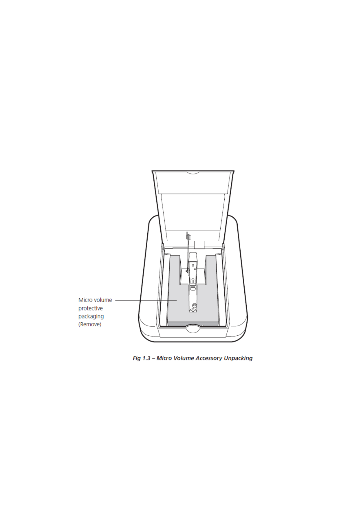
1.3 UNPACKING
Please check that the following items are included in the packaging:
• Genova Nano spectrophotometer (737 503)
• 4GB USB memory stick (019 146)
• Universal power supply 24V, 65W (021 060)
• Calibration standards with certificate (035 092)
• Genova Nano instruction manual (737 555)
• Genova Plus instruction manual (736 505)
The Genova Nano is delivered with the micro volume accessory securely packaged in the
spectrophotometers sample chamber.
Note: The protective packaging must be removed before the instrument is first initialised.
10
Page 11

SECTION 2 – ACCESSORY LAYOUT AND INSTALLATION
2.1 ACCESSORY LAYOUT
2.2 INITIALISATION
Connect the power supply unit to the power inlet socket on the rear panel of the instrument and
connect to the mains socket. Turn the power on at the mains and switch the instrument on using
the power switch on the rear of the instrument.
The instrument will initially check for firmware updates and then perform several power-on tests
before displaying the main menu:
Fig 2.2 – Genova Nano Main Menu
Note: The instrument will return to the last main menu used.
11
Page 12

SECTION 3 – MICRO-VOLUME SETTINGS
Tick icon
3.1 ACCESSING THE MICRO VOLUME SETTINGS
The micro volume icon is displayed in the bottom right hand corner of the screen in each
measurement mode.
Micro Volume Icon
Fig 3.1 – Accessing the Micro Volume Settings Menu
The micro volume settings are accessed by pressing the key below the micro volume icon.
The micro volume settings allow the user to select the required path length (0.2mm or 0.5mm)
for a measurement and to calibrate the accessory using a standard solution with known
absorbance values at 260 and 330nm.
0.2mm Path Length
Setting
0.5mm Path Length
Setting
Auto Path Length
Setting
Path Length
Calibration
Current Calibration
Factors
Alignment Mode
A
Calibration
260
Standard Value
A
Calibration
330
Standard Value
Calibration Standard
Path Length Value
Fig 3.2 – Micro Volume Settings Menu
12
Page 13

3.2 PATH LENGTH SELECTION
Mode
Auto path length availability
3.2.1 Known Path Length Measurements
3.2.2 Unknown Path Length Measurements
If the required measurement path length is
known it can be selected by pressing the button
adjacent to the 0.2mm or 0.5mm path length
setting icons. The selected setting is indicated
by an icon with a black background. Once the
required path length setting has been selected
press the button adjacent to the tick icon to
confirm.
If the required measurement path length is not
known in selected modes the auto path length
setting can be selected by pressing the button
adjacent to the auto path length setting icon.
Once the auto path length setting has been
selected press the button adjacent to the tick
icon to confirm.
The auto path length measurement setting will firstly measure a sample using the 0.5mm path
length setting. If the measured photometric value is within range, the value will be displayed on
screen and no more measurements are taken. If however the measured value is over-range, the
sample will be re-measured using the 0.2mm path length setting.
3.2.3 Auto Path Length Availability
Photometrics Available
Spectrum, purity scan Not available
Concentration, concentration plus Available
Kinetics Not available
Multi wavelength, multi wavelength plus Available
Quantitation Not available
Protein (quantitative assay modes) Not available
Protein (direct UV) Available
DNA (all modes) Available
OD 600 Available
13
Page 14

SECTION 4 – PERFORMING MICRO VOLUME MEASUREMENTS
For detailed descriptions of the measurement modes that are available on the Genova Nano
spectrophotometer please refer to the supplied Genova Plus operating manual.
4.1 PIPETTING SAMPLES ONTO THE MICRO VOLUME READ HEAD
The Genova Nano spectrophotometer is designed to measure sample volumes ranging from
0.5µl to 5.0µl.
Jenway recommends that users should, if possible, use at least 2µl of sample for their
measurements.
1. With the read head mechanism open,
pipette the liquid to be analysed onto the
centre of the lower read head. Ensure
there are no bubbles in the sample.
Pipetting a sample onto the read head
Read head in rest position
2. Close the lid of the spectrophotometer.
This will lower the read head assembly
down onto the path length drive motor. The
upper read head will now be in the rest
position, 2mm above the lower read head.
3. When a measurement is initiated, the path
length drive motor lowers the upper read
head to the specified measurement
distance, the photometric measurement is
taken and the upper read head is then
returned to the rest position.
Read head in measurement position
14
Page 15

4.2 SAMPLE RECOVERY OR REMOVAL
Once a measurement is complete, the sample solution can be recovered from the lower read
head with a suitable pipette or removed from the read heads by cleaning with a suitable lint
free cloth.
1. Open the lid of the spectrophotometer.
The read head mechanism will open to
allow access to the upper and lower read
heads
2. The sample can be recovered by carefully
drawing the liquid that is retained on the
lower read head into a clean pipette tip.
3. Both read heads should then be wiped
with a lint free cloth.
4. More rigorous cleaning may be required after the measurement of high concentration
samples or samples that pose a contamination risk. See section 8 for further details.
15
Page 16

SECTION 5 – TOP 10 TIPS FOR SAMPLE MEASUREMENT
1. Ensure the read heads are clean. Wipe both the upper and lower read heads with a lint-free
cloth wetted with deionised water to remove any residues of previous samples. Dry with a fresh
cloth.
2. If a stable droplet does not form, “buff” the read head surfaces by rubbing aggressively with a
dry laboratory wipe 30-40 times. This will “re-condition” the surface.
3. Make sure that the sample is well mixed and free of air bubbles or particles. If a bubble is
created when pipetting the sample, remove the sample and repeat the application.
4. If possible use at least 2µl of sample for measurement. When measuring at 0.2mm path length,
a minimum of 0.5µl can be used.
5. Read each sample droplet only once. The read head moves into a default position after the
sample has been measured. This means that if the sample is measured a second time, contact
of the droplet with the read heads could be lost and the subsequent reading will not give a valid
result.
6. Use a sample of sufficient concentration. Remember that the short path length creates a “virtual
dilution” of the sample of 1 in 20 at 0.5mm and 1 in 50 at 0.2mm. This means that a sample
which would normally read an absorbance of 1.0 in a standard 10mm cuvette will only give a
value of 0.05 at 0.5mm or 0.02 at 0.2mm.
7. To minimise any factors which may interfere with a reading such as sample turbidity or
contaminants carried over from sample preparation, it is recommended that a background
reading is also made at a second reference wavelength (where the absorbance of the sample
is very low and unchanging). In the nucleic acid and protein direct UV modes this option is
defaulted to ON at a wavelength of 320nm; this can be deactivated if required.
8. Use the same measurement mode if comparing the concentrations of samples. Different modes
use different equations to calculate the final sample concentration.
9. Be aware that when measuring micro volume samples, very small changes in absorbance can
lead to much greater differences in calculated concentration values due to the inherent “dilution”
factor of the small path length. For example, when measuring dsDNA, an absorbance change
of just 0.001 equates to a derived concentration change of 1µg/ml at 0.5mm path length (based
on 1 A260 unit of dsDNA = 50µg/ml).
10. Jenway recommends that the micro volume accessory is calibrated every 6 months A set of
calibration solutions (Part code 035 092) are supplied with the Genova Nano
spectrophotometer for this purpose. Full instructions are given in Section 7.
16
Page 17

SECTION 6 – STEP BY STEP GUIDE TO MAKING A DNA MEASUREMENT
The DNA measurement mode of the Genova Nano allows the user to select a method from a list of
common nucleic acid measurement tests, including single wavelength concentration
measurements for dsDNA, ssDNA, RNA and Oligonucleotides and methods that use absorbance
ratios for estimating nucleic acid purity, such as 260nm/280nm and 260nm/230nm. Section 14 of
the Genova Plus manual gives further details of the DNA measurement modes.
6.1 dsDNA Mode
This mode simply multiplies the A260 reading by a factor of 50 for dsDNA to calculate the
concentration in µg/ml. An additional factor for the path length is also included automatically by the
instrument.
1. From the Life Science screen select the DNA mode: , followed by dsDNA.
2. Press the button next to the Settings Menu icon: and check that the wavelength is set to
260nm, the units are µg/ml and F1 = 50.
3. Lift the lid of the Genova Nano and pipette 2µl of water onto the read head. Close the lid.
Perform the Blank Reading:
4. Lift the lid and wipe the water from both the upper and lower read heads.
5. Pipette 2µl of the DNA sample onto the read head. Close the lid and perform the Sample
Reading: . Record the results.
6.2 A260/280 Mode
This method uses the equation:
Concentration (µg/ml) = (Abs@260nm x 62.9) - (Abs@280nm x 36.0).
This equation takes into account any contamination present which may absorb at 280nm (e.g.
protein).
1. From the Life Science screen select the DNA mode: , followed by 260/280.
2. Press the button next to the Settings Menu icon: . Check that the settings are as follows:
Wavelength 1: 260; Wavelength 2: 280; Wavelength 3: 230; units, µg/ml.
3. Touch the button next to the Calculation Factors icon: and check that Factor 1 = 62.9;
Factor 2 = 36.0; Sum,=(xF1*A1)-(xF2*A2).
4. Press the button next to the Tick icon twice to return to the measurement screen.
17
Page 18

5. Lift the lid of the Genova Nano and pipette 2µl of water onto the read head. Close the lid.
Perform the blank reading.
6. Lift the lid and wipe the water from both the upper and lower read heads.
7. Pipette 2µl of the DNA sample onto the read head. Close the lid and perform the DNA reading.
Record the results.
6.3 Multi-wavelength Mode
This mode simply calculates the DNA concentration by multiplying by the factor 50 for dsDNA but
also allows correction by a reference wavelength at 320nm.
1. From the Life Science screen select the Multiwavelength mode: .
2. Press the button next to the Settings Menu icon: . Check that the settings are as follows:
Wavelength 1: 260; Wavelength 2: 280; Wavelength 3: 230. Activate the reference Wavelength
4, 320nm. The units are µg/ml.
3. Touch the button next to the Calculation Factors icon: and check that Factor 1 = 50;
Factor 2 = 0 and the Sum = (xF1*(A1-A4))-(xF2*(A2-A4)).
4. Press the button next to the Tick icon twice to confirm and return to the measurement screen.
5. Set the path length to 0.5mm. Press the button next to the Tick icon to confirm.
6. Lift the lid of the Genova Nano and pipette 2µl of water onto the read head. Close the lid.
Perform the blank reading.
7. Lift the lid and wipe the water from both the upper and lower read heads.
8. Pipette 2µl of the DNA sample onto the read head. Close the lid and perform the DNA reading.
Record the results.
18
Page 19

SECTION 7 – CALIBRATION OF THE MICRO VOLUME ACCESSORY
Jenway recommends that the micro volume accessory is calibrated every 6 months. A set of calibration
solutions (Part code 035 092) are supplied with the Genova Nano spectrophotometer. Please note that
the calibration solutions should be discarded 1 week after being opened.
When using the calibration solutions we advise the use of chemically resistant gloves and googles and
that there is eye wash available immediately. We recommend safe handling of the calibration solution avoid skin contact, direct inhalation or ingestion of the standards as advised in the MSDS.
7.1 CALIBRATION SOLUTIONS (035 092)
The supplied calibration solution set consists of two
vials.
1. Matrix Blank (White)
2. 10x ref - Calibration Standard (Blue)
A calibration certificate is supplied that details the
certified absorbance values of the calibration
standard and the path length at which these values
7.2 MICRO VOLUME CALIBRATION PROCEDURE
7.2.1 Micro Volume Settings
7.2.2 Calibration Standard - Data Entry
were determined.
The micro volume settings can be accessed by
pressing the key below the Micro Volume icon in
any of the Genova Nano’s operating modes.
1. Enter the A260 and A330 DNA standard
solution values given on the calibration
certificate into the accessory settings by
pressing the key adjacent to the Calibration
Standard Value icon.
19
Page 20

2. Select the digit to be changed using the keys at
the bottom of the screen. Use the keys adjacent
to the Arrow icons to increase or decrease the
number. Press the key adjacent to the Tick icon
to save any changes.
3. Enter the stated path length in mm (1.0mm for
the supplied calibration standard solution set)
for the DNA standard solution into the accessory
settings by pressing the key adjacent to the
Calibration Standard Path Length Value icon.
4. Select the digit to be changed using the keys at the bottom of the screen. Use the keys adjacent
to the Arrow icons to increase or decrease the number. Press the key adjacent to the Tick icon
to save any changes.
7.2.3 Calibration and Verification
If an error message is displayed during the calibration and verification procedure, refer to
Section 11 for further details.
1. The calibration sequence is initiated by pressing
the key adjacent to the Path Length Calibration icon.
2. The Air Measurement icon will be displayed. If a USB stick is inserted into the unit, a Save icon
will also be displayed.
20
Page 21

During the calibration process, there is the option to log the calibration data to USB stick. This
generally isn’t needed, but if you experience difficulties in performing a successful calibration you
can forward the calibration log data to techsupport@bibby-scientific.com for further advice.
By default, the calibration data logging is disabled. To
enable this function, press the key adjacent to the Save
icon. The Save icon will become reversed to indicate
that logging is enabled.
Pressing the key adjacent to the Save icon again will disable this feature. This can be enabled or
disabled whenever the Save icon is displayed.
Use a lint free cloth to clean the upper and lower read heads, close the instrument lid and press the
key adjacent to the Tick icon to continue. Pressing the key adjacent to the Cross icon will return
the instrument to the micro volume settings menu screen.
The unit takes three dark and light readings at 260 and 330nm, at both 0.5mm and 0.2mm path
lengths.
3. The Blank Solution Measurement icon will be
displayed. Open the instrument lid and pipette a 2.0µl
aliquot of the matrix blank solution onto the lower read
head. Close the instrument lid and press the key
adjacent to the Tick icon to initiate the blank
measurement.
4. The unit takes three readings at 260 and 330nm, at both 0.5mm and 0.2mm path lengths. At the
end of the readings, the unit will display the results of the measurements taken:
A260.5 -0.011 [-0.040 to 0.000]
A330.5 -0.010 [-0.040 to 0.000]
A260.2 -0.026 [-0.040 to 0.000]
A330.2 -0.024 [-0.040 to 0.000]
A260.5 indicates the Absorbance calculated at 260nm at 0.5mm path length. The values in square
brackets are the acceptable limits for this particular test. In the above example, the Absorbance at
260nm at 0.5mm path length is -0.011Abs, which is within the permitted range of -0.040 Abs to
0.000 Abs.
21
Page 22

5. If the measured values are within the required tolerances, the Passes Test icon will be displayed.
Press the button adjacent to the Tick icon to continue or the button adjacent to the Cross icon
to abort the calibration process.
6. The Calibration Solution Measurement icon will
be displayed. Open the instrument lid and use a lint free
cloth to clean the read heads.
7. Pipette a 2.0µl aliquot of the calibration solution onto the lower read head. Close the instrument
lid and press the key adjacent to the Tick icon to initiate the calibration solution measurement.
8. The unit takes three readings at 260 and 330nm, at both 0.5mm and 0.2mm path lengths. At the
end of the readings, the unit will display the results of the measurements taken:
A330.5 0.006 [0.050]
A330.2 0.006 [0.050]
A.5 0.5341(0.4899), A.2 0.2279(0.1959)
The readings at this stage are validated by examining the Absorbance at 330nm – used for
background correction of the readings at 260nm. The background corrected Absorbances at
0.5mm and 0.2mm pathlength are also shown. If the Absorbance values at 330nm are below the
values shown in square brackets, the measurements are considered valid.
9. If the measured values are within the required tolerances, the Passes Test icon will be displayed.
Press the button adjacent to the Tick icon to continue or the button adjacent to the Cross icon
to abort the calibration process.
10. The Calibration Solution Measurement icon will
be displayed for a second time. Open the instrument lid
and use a lint free cloth to clean the read heads.
11. Pipette a 2.0µl aliquot of the calibration solution onto the lower read head. Close the instrument
lid and press the key adjacent to the Tick icon to initiate the calibration solution measurement.
22
Page 23

12. The unit takes three readings at 260 and 330nm, at both 0.5mm and 0.2mm path lengths. At the
end of the readings, the unit will display the results of the measurements taken:
A330.5 0.006 [0.050]
A330.2 0.006 [0.050]
A.5 0.5349(0.4899), A.2 0.2306(0.1959)
13. If the measured values are within the required tolerances, the Passes Test icon will be displayed.
Press the button adjacent to the Tick icon to continue or the button adjacent to the Cross icon
to abort the calibration process.
14. The instrument will then display the pathlength factors for both 0.2mm and 0.5mm pathlengths.
F.2 0.85 [0.70]
F.5 0.92 [0.70]
If the values displayed are within the tolerance indicated in the square brackets, the Passes Test
icon will be displayed. Press the button adjacent to the Tick icon to continue or the button adjacent
to the Cross icon to abort the calibration process.
15. The new calibration factor values must now be verified by re-measuring the air, blank and
standard values.
16. The Air Measurement icon will be displayed.
Open the instrument lid and use a lint free cloth to clean
the read heads. Close the instrument lid and press the
key adjacent to the Tick icon to initiate the blank
measurement.
17. The unit takes two dark and light readings at 260 and 330nm, at both 0.5mm and 0.2mm path
lengths.
18. The Blank Solution Measurement icon will be
displayed. Open the instrument lid and pipette a 2.0µl
aliquot of the matrix blank solution onto the lower read
head. Close the instrument lid and press the key
adjacent to the Tick icon to initiate the blank
measurement.
23
Page 24

19. The unit takes two readings at 260 and 330nm, at both 0.5mm and 0.2mm path lengths. At the
end of the readings, the unit will display the results of the measurements taken:
A260.2 -0.024 [-0.040 to 0.000]
A330.2 -0.021 [-0.040 to 0.000]
A260.5 -0.010 [-0.040 to 0.000]
A330.5 -0.009 [-0.040 to 0.000]
20. If the measured values are within the required tolerances, the Passes Test icon will be displayed.
Press the button adjacent to the Tick icon to continue or the button adjacent to the Cross icon
to abort the calibration process.
21. The Calibration Solution Measurement icon will
be displayed. Open the instrument lid and use a lint free
cloth to clean the read heads Open the instrument lid
and pipette a 2.0µl aliquot of the calibration solution
onto the lower read head. Close the instrument lid and
press the key adjacent to the Tick icon to initiate the
calibration solution measurement.
22. The unit takes two readings at 260 and 330nm, at both 0.5mm and 0.2mm path lengths. The
variation from the expected Absorbance values are displayed.
F.5 0.57 [2.00%]
F.2 0.37 [2.00%]
23. If the measured values are within the required tolerances – indicated by the value in square
brackets - the Passes Test icon will be displayed. Press the button adjacent to the Tick icon to
continue or the button adjacent to the Cross icon to abort the calibration process
24. Following successful calibration, the instrument display will return to the micro volume accessory
settings screen and the new path length calibration factors will be shown.
24
Page 25

SECTION 8 – CLEANING AND DECONTAMINATION
8.1 CLEANING
Wiping the sample from both the upper and lower read heads upon completion of each sample
measurement with a lint free cloth is usually sufficient to prevent sample carryover and avoid residue
buildup. Although generally not necessary, water aliquots can be used to clean the measurement
surfaces after the measurement of particularly highly concentrated samples to ensure no residual
sample is retained on either read head. After measuring a large number of samples, it is recommended
that the areas around the upper and lower pedestals are cleaned thoroughly. This will prevent spread
of contamination from previous samples onto the measurement pedestals which could affect subsequent
low-level measurements. A final cleaning of all surfaces with deionised water is also recommended after
the last measurement.
8.2 DECONTAMINATION
If decontamination is necessary, a sanitising solution, such as a 0.5% solution of sodium hypochlorite
(1:10 dilution of common commercial bleach solutions – freshly prepared), can be used to ensure that
no biologically active material is present on the measurement read heads. The read head fittings are
made from stainless steel and are resistant to most common laboratory solvents. See Section 13 Chemical Compatibility for full details.
8.3 READ HEAD RECONDITIONING
Reagents containing surfactants can “un-condition” the measurement read head surfaces so that the
liquid does not form a stable sample droplet. If this occurs, “buff” the read head surfaces by rubbing
each measurement surface aggressively with a dry laboratory wipe 30-40 times. This will “re-condition”
the surface allowing the sample droplet to form.
25
Page 26

SECTION 9 – ACCESSORIES
P
art Code
Description
9.1 ACCESSORIES
035 092 Calibration solution set
SECTION 10 – MAINTENANCE AND SERVICE
10.1 ROUTINE MAINTENANCE
Ensure the external surfaces of the unit are clean and free from dust. The sample area should
always be kept clean and any accidental spillage should be wiped away immediately.
10.2 SERVICE
Our dedicated service team are on hand to help in the unlikely event that your Jenway equipment
develops a fault. Please contact them by one of the following means stating the serial number of
the unit and a clear description of the problem:
E-mail: service@bibby-scientific.com
Tel: +44 (0) 1785 810475
On occasion it may be necessary for your equipment to be sent back to our Service Department for
repair. In this case please contact the Service Department for a reference number which you should
include with your faulty equipment. Please also ensure you include a clear description of the fault
and a completed copy of our Decontamination Certificate. This is available as a downloadable pdf
file at www.jenway.com or contact us and we will send a copy to you. Please clearly mark the
package for the attention of the Service Department and post to the following address:
Bibby Scientific Ltd
Beacon Road
Stone
Staffordshire
ST15 0SA
United Kingdom
All replacement parts are guaranteed for 1 year and wherever possible, returned equipment is
turned around in 10 working days.
26
Page 27

SECTION 11 – TROUBLESHOOTING
Error Code
Symbol
Issue
9
11
11.1 CALIBRATION ERROR CODES
If an error code is displayed during calibration it will be accompanied by a Clipboard icon and a
number to indicate the cause of the error. The first time that an error is displayed, it will be possible
to repeat the erroneous measurement. If the same error message is shown after the repeat
measurement, the complete calibration process will need to be repeated. The table below shows
the error codes:
11.1.1 Calibration Procedure Error Codes
1
3
5
7
8
11.1.2 Verification Check Error Codes
Blank solution reading outside of acceptable range
Calibration solution reading outside of acceptable range
Duplicate calibration solution readings outside of acceptable
range
0.2mm path length factor outside of acceptable range
0.5mm path length factor outside of acceptable range
Blank solution reading outside of acceptable range
Calibration solution reading outside of acceptable range
27
Page 28

11.2 TROUBLESHOOTING GUIDE
Issue Solution
Ensure that there is not a sample on the micro volume
Unable to achieve zero
absorbance or 100% transmittance
when calibrating
Unable to achieve a reading when
measuring a sample
11.3 TECHNICAL SUPPORT
Jenway have a dedicated Technical Support team made up of experienced scientists who are on
hand to help with any applications advice and questions you may have about our products or how
to use them. If you require any technical or application assistance please contact the team at:
E-mail: techsupport@bibby-scientific.com
accessories read head.
Ensure the instrument lid is closed before and during the
calibration.
Ensure the lamp is working – if the lamp has failed please
request service assistance.
Ensure the correct path length is being used.
Ensure the sample isn’t so dense so that light is not
transmitted through the sample.
Ensure the lamp is working.
Phone: +44 (0)1785 810433
28
Page 29

SECTION 12 – GLOSSARY OF ICONS
Description
Mode ICON
Common
Common
Common
Common
Common
Settings
Settings
Settings
Settings
Settings
Back key
Tick icon - Done/yes
Cross icon – Cancel/no
Arrow icon – Move down, decrease
Arrow icon – Move up, increase
0.2mm path length setting / selected
0.5mm path length setting / selected
Auto path length setting / selected
Path length calibration
260nm Calibration standard absorbance value
Settings
Settings
Settings
Calibration
Calibration
Calibration
Calibration
Calibration
330nm Calibration standard absorbance value
Calibration standard path length value
Micro volume alignment
Air measurement
Blank solution measurement
Calibration solution measurement
Passes test
Fails test
29
Page 30

SECTION 13 – CHEMICAL COMPATABILITY
Assay Chemical Concentration
BCA Sodium bicinchoninate 1%*
BCA Sodium carbonate 2%*
BCA Sodium tartrate 0.16%*
BCA Sodium hydroxide 0.1M*
BCA Sodium bicarbonate 0.95%*
BCA Copper (II) sulphate 0.08%
Biuret Sodium potassium tartrate 0.9%*
Biuret Copper (II) sulphate 0.3%*
Biuret Potassium iodide 0.5%*
Biuret Sodium hydroxide 0.08M
Lowry Sodium carbonate 1.6%
Lowry Copper (II) sulphate 0.032%
Lowry Sodium potassium tartrate 0.016%
Lowry Sodium dodecyl sulphate 0.08%
Lowry Sodium hydroxide 0.08M
Lowry Folin reagent (lithium and sodium
molybdotungstophosphate solution
Bradford Coomassie brilliant Blue G-250 0.01%*
Bradford Ethanol 4.75%*
Bradford Phosphoric acid 8.5%*
Bradford Sodium hydroxide 0.1M
DMSO 10%
Acetonitrile OK
Methanol OK
2-Propanol OK
0.04N*
*Highest concentration
30
Page 31

Bibby Scientific Ltd
Beacon Road Stone
Staffordshire ST15 0SA
United Kingdom
Tel: +44 (0)1785 812121
e-mail: info@bibby-scientific.com
www.bibby-scientific.com
31
 Loading...