

Page 1

Spectrophotometer
Model 7200
Operating Manual
720 005 REV A 07/13
Page 2

Page 3
Safety
Please read this information carefully prior to installing or using this equipment.
1. The unit described in this manual is designed to be operated only by trained personnel. Any
adjustments, maintenance and repair must be carried out as defined in this manual, by a person
qualified to be aware of the hazards involved.
2. It is essential that both operating and service personnel employ a safe system of work, in
addition to the detailed instructions specified in this manual.
3. Other than for those items defined in the maintenance procedures herein there are no user
serviceable items in this instrument. Removal of covers and attempted adjustment or service
by unqualified personnel will invalidate the warranty and may incur additional charges for repair.
4. References should always be made to the Health and Safety data supplied with any chemicals
used. Generally accepted laboratory procedures for safe handling of chemicals should be
employed. Do not use hazardous or flammable substances in the instrument.
5. If it is suspected that safety protection has been impaired in any way, the unit must be made
inoperative and secured against any intended operation. The fault condition should immediately
be reported to the appropriate servicing authority.
6. The warning symbol alerts the user to important information about using the instrument. Read
and follow the associated instructions carefully.
7. This instrument uses a UV light source. Do not look directly at the light source.
8. WARNING: If the equipment is not used in the manner specified, the protection provided by the
equipment may be impaired.
9. Do not replace the detachable mains leads with inadequately rated leads.
Merci de lire attentivement ces informations avant d’installer ou d’utiliser cet appareil.
1. L’appareil décrit dans ce manuel est conçu pour être utilisé uniquement par des personnes
formées. Tout réglage, maintenance ou réparation doit être effectué comme décrit dans ce
manuel, par une personne qualifiée consciente des risques encourus.
2. Il est essentiel que les personnes utilisant et intervenant sur cet appareil respectent les règles
de sécurité de travail, en plus des instructions détaillées précisées dans ce manuel.
3. En-dehors des éléments décrits dans les procédures de maintenance ci-incluses, cet appareil
ne contient aucun élément réparable par l’utilisateur. L’enlèvement des capots et les tentatives
de réglage ou de réparation par des personnes non qualifiées invalide toute garantie et entraîne
un risque de frais de réparation supplémentaires.
4. Toujours se référer aux fiches techniques de santé et de sécurité accompagnant tout produit
chimique utilisé. Respecter les procédures de laboratoire généralement acceptées pour la
manipulation en toute sécurité des produits chimiques. Ne pas utiliser de substances
dangereuses ou inflammables sur l’appareil.
3
Page 4

5. Si l’utilisateur suspecte qu’un problème quelconque puisse mettre en cause la sécurité,
l’appareil doit être rendu inopérant en empêchant son utilisation. Communiquer la défaillance
constatée au service de maintenance compétent.
6. Le symbole d’alerte signale à l’utilisateur les informations importantes concernant l’utilisation
de l’appareil. Lire et suivre les instructions fournies avec la plus grande attention.
7. Cet appareil utilise une source lumineuse UV. Ne pas regarder directement vers la source.
8. ATTENTION. Si l’appareil n’est pas utilisé de manière adéquate, la protection de l’appareil
pourrait être impactée.
9. Ne pas remplacer le cordon d’alimentation fourni par un cordon d’alimentation de dimension
électrique non adapté.
Bitte lesen Sie diese Hinweise vor Installation oder Gebrauch dieser Ausrüstung sorgfältig durch.
1. Das in diesem Handbuch beschriebene Gerät darf nur von geschultem Personal bedient
werden. Alle Anpassungen, Wartungsarbeiten und Reparaturen müssen entsprechend der
Vorgaben in diesem Handbuch und von einer kompetenten Person, die mit den damit
verbundenen Gefahren vertraut ist, durchgeführt werden.
2. Es ist wichtig, dass sowohl das Bedienungs- als auch das Service-Personal zusätzlich zu den
detaillierten Anweisungen in diesem Handbuch ein sicheres Arbeitssystem einsetzen.
3. Mit Ausnahme der Teile, deren Wartungsverfahren in diesem Handbuch beschrieben sind,
enthält dieses Gerät keine weiteren Teile, die vom Benutzer gewartet werden können. Das
Entfernen von Abdeckungen und Versuche von hierfür unqualifiziertem Personal,
Anpassungen oder Wartungsarbeiten durchzuführen, haben zur Folge, dass die Garantie
verfällt und können zusätzliche Reparaturkosten auslösen.
4. Es ist jederzeit auf die sicherheitsrelevanten Daten sämtlicher verwendeter Chemikalien Bezug
zu nehmen. Allgemein anerkannte Labormethoden zum sicheren Umgang mit Chemikalien
sollten eingesetzt werden. Verwenden Sie keine gefährlichen oder entzündlichen Stoffe in
Verbindung mit dem Gerät.
5. Besteht der Verdacht, dass die Sicherheitsvorrichtungen in irgendeiner Weise beschädigt
wurden, muss das Gerät außer Betrieb genommen und gegen weiteren Gebrauch gesichert
werden. Die Störung sollte der zuständigen Serviceeinrichtung unverzüglich gemeldet werden.
6. Das Warnsymbol weist auf wichtige Informationen zur Verwendung des Geräts hin. Lesen und
befolgen Sie die dazugehörigen Anweisungen sorgfältig.
7. Dieses Instrument greift auf eine UV-Lichtquelle zurück. Nicht direkt in die Lichtquelle schauen.
4
Page 5
8. ACHTUNG: Wenn das Gerät nicht in der vorgegebenen Weise eingesetzt wird, können die
Schutzfunktionen des Gerätes beeinträchtigt werden.
9. Abnehmbares Anschlusskabel nicht durch unangemessen bewertete Kabel austauschen.
Leggere attentamente queste istruzioni prima di installare o utilizzare il dispositivo.
1. L’unità descritta nel presente manuale è stata realizzata per essere utilizzata solo da personale
che ha ricevuto l’apposita formazione. Qualsiasi operazione di regolazione, manutenzione e
riparazione deve essere effettuata sulla base di quanto indicato nel presente manuale da
personale qualificato consapevole dei rischi connessi.
2. È fondamentale che il personale operativo e il personale addetto alla manutenzione utilizzino
un sistema di lavoro sicuro, oltre a seguire le istruzioni specificate nel presente manuale.
3. Oltre a quelli indicati nelle procedure di manutenzione, all’interno di questo dispositivo non sono
presenti altri elementi sui quali è possibile effettuare interventi. La rimozione delle protezioni e
qualsiasi tentativo di regolazione o di manutenzione posto in essere da personale non qualificato
invaliderà la garanzia. In questi casi, sarà necessario pagare un importo per le riparazioni
effettuate.
4. È sempre necessario fare riferimento ai dati sulla salute e sulla sicurezza forniti con le sostanze
chimiche utilizzate. Adottare le procedure di laboratorio generalmente accettate per la gestione
delle sostanze chimiche. Non utilizzare sostanze pericolose o infiammabili sullo strumento.
5. Nel caso in cui si sospetti che la salute possa essere pregiudicata in qualsiasi modo, disattivare
l’unità per renderla inutilizzabile. Qualsiasi condizione di errore deve essere immediatamente
segnalata al responsabile per la manutenzione.
6. Il simbolo di avvertenza informa l’utente sulle informazioni importanti in merito all’uso dello
strumento. Leggere e seguire le istruzioni corrispondenti con cura.
7. Questo strumento utilizza una sorgente di luce UV. Non guardare direttamente la sorgente di
luce.
8. AVVERTENZA: qualora il dispositivo non venga utilizzato nel modo descritto, la protezione
fornita dal dispositivo stesso potrebbe risultare compromessa.
9. Non sostituire i cavi di alimentazione di rete scollegabili con cavi inadeguati.
Lea esta información atentamente antes de instalar o utilizar este equipo.
1. La unidad descrita en este manual está diseñada para que solamente la utilice personal con
formación. Cualquier operación de ajuste, mantenimiento y reparación debe llevarse a cabo
del modo indicado en este manual y debe realizarla una persona cualificada que sea
consciente de los peligros que implica.
2. Es fundamental que tanto los operarios como el personal de servicio utilicen un sistema de
trabajo seguro, así como las instrucciones detalladas que se especifican en este manual.
5
Page 6
3. Cualquier elemento que no se encuentre entre los definidos en los procedimientos de
mantenimiento aquí descritos no podrá utilizarse en este instrumento. La extracción de las
tapas y los intentos de ajuste o reparación por parte de personal no cualificado invalidarán la
garantía y pueden incurrir en cargos adicionales por reparación.
4. Siempre deberían consultarse los datos sobre Salud y Seguridad que se suministran con
cualquier producto químico que se utilice. Es necesario llevar a cabo los procedimientos de
laboratorio de aceptación generalizada para la manipulación segura de productos químicos.
No utilice sustancias peligrosas o inflamables en el instrumento.
5. Si existe la sospecha de que las medidas protectoras de seguridad han quedado dañadas en
cualquier modo, la unidad debe inutilizarse y protegerse contra toda operación que se intente
llevar a cabo. El estado de fallo debe comunicarse inmediatamente a la autoridad de servicio
de mantenimiento y reparación pertinente.
6. El símbolo de advertencia avisa al usuario de información importante relacionada con el uso
del instrumento. Lea atentamente y siga las instrucciones correspondientes.
7. Este instrumento utiliza una fuente de luz UV. No mire directamente a la fuente de luz.
8. ADVERTENCIA: Si el equipo no se utiliza de la manera especificada, la protección que ofrece
el aparato puede verse afectada.
9. No sustituya el cable de alimentación eléctrica con cables de voltaje inadecuado.
6
Page 7

Contents
Page
Safety 3
SECTION 1 - Introduction 11
1.1 Instrument description 11
1.2 Instrument specification 12
SECTION 2 - Installation 13
2.1 Unpacking 13
2.2 Installation 13
2.3 Rear panel 14
2.4 Front access panel 14
2.5 Lamp access panel 15
2.6 Display 15
SECTION 3 - Theory and practice of spectroscopy measurements 16
3.1 Theory of spectroscopy measurement 16
3.2 Spectroscopy measurement 17
3.3 Good practice guidelines 17
SECTION 4 - Instrument setup 19
4.1 Navigating and screen setup 19
4.2 Instrument settings screen 19
4.3 Printing and saving 20
4.4 Heated cell accessory control 21
4.5 Date and time 22
4.6 Language 23
4.7 Software update 23
SECTION 5 - Single wavelength 25
5.1 Simple (ABS/%T) measurement mode 26
5.1.1 Method set up 26
5.1.2 Selecting a wavelength 26
5.1.3 Measurement name 27
5.1.4 Blank calibration and sample measurement 27
5.2 Optical density measurement mode 28
5.2.1 Method setup 28
5.2.2 Selecting a wavelength 29
5.2.3 Measurement name 29
5.2.4 Entering a factor 29
7
Page 8

5.2.5 Entering concentration units 30
5.2.6 Blank calibration and sample measurement 30
5.3 Use a factor measurement mode 31
5.3.1 Method setup 32
5.3.2 Selecting a wavelength 32
5.3.3 Measurement name 32
5.3.4 Entering a factor 33
5.3.5 Units of measure 33
5.3.6 Blank calibration and sample measurement 33
5.4 Use standard(s) measurement mode 35
5.4.1 Method setup 35
5.4.2 Selecting a wavelength 36
5.4.3 Measurement name 36
5.4.4 Entering concentration units 36
5.4.5 Selecting the number of standards and replicates 37
5.4.6 Measuring standards 37
5.4.7 Load standard curve 39
5.5 Blank calibration and sample measurement 40
SECTION 6 - Spectrum 42
6.1 Method setup 42
6.1.1 Measurement name 42
6.1.2 Selecting measurement mode 43
6.1.3 Setting start and end wavelengths 43
6.2 Blank calibration and sample measurement 44
6.3 Data analysis 45
6.3.1 Spectrum zoom 45
6.3.2 Spectral points analysis 46
SECTION 7 - Kinetics 47
7.1 Method setup 47
7.1.1 Measurement name 47
7.1.2 Selecting number of wavelengths 48
7.1.3 Selecting measurement mode 48
7.1.4 Run time 48
7.1.5 Lag time (seconds) 48
7.1.6 Selecting concentration units 49
7.1.7 Selecting a wavelength and factor 49
7.2 Blank calibration and sample measurement 50
7.3 Post measurement analysis 51
8
Page 9

SECTION 8 - Glossary of icons 52
SECTION 9 - Accessories and spare parts 54
9.1 Optional accessories 54
9.2 Connecting the accessories 54
9.2.1 External printer 54
9.2.2 Passive accessories 54
9.2.3 Active accessories 55
9.3 Spares 56
SECTION 10 - Maintenance and service 57
10.1 Routine maintenance and cleaning 57
10.2 Lamp replacement 57
10.2.1 Halogen lamp module replacement 57
10.3 Firmware update procedure 59
10.4 Service 59
SECTION 11 - Troubleshooting 60
11.1 Error codes 60
11.2 Troubleshooting guide 64
11.3 Technical support 64
SECTION 12 - Declaration of conformity 65
9
Page 10

10
Page 11

SECTION 1 - Introduction
1.1 INSTRUMENT DESCRIPTION
Model 7200 is a visible diode array spectrophotometer which is suited to a wide range of applications
in education, quality control, environmental and clinical analysis. This spectrophotometer covers a
wavelength range from 335nm to 800nm, with measurement modes for photometrics, concentration,
spectrum scanning, quantitation and kinetics. This spectrophotometer has a touchscreen user interface
for improved navigation.
11
Page 12

1.2 INSTRUMENT SPECIFICATION
7200
Wavelength
Range 335 to 800nm
Accuracy ± 2nm
Repeatability ± 2nm
Spectral bandwidth 7nm
Photometrics
Absorbance -0.300 to 2.500A
Accuracy +/- 0.01A at 1.0A and 546nm
Stability (A) +/- 0.005A/h at 0.04A and 546nm
Noise +/- 0.002A at 0.04A and +/- 0.02A at 2.0A and 546nm
Stray Light at 340nm, %T <1%T according to ANSI/ASTM E387-72
Concentration
Range +/- 2500
Calibration Blank with a single standard or factor
Factor +/- 1000
Standard +/- 1000
Optical Density
Factor +/- 1000
Quantitation
Range +/- 2500
Calibration Blank with up to 6 standards
Curve fit algorithms Linear and linear through zero
Kinetics
Measurement Time 15 to 9999 seconds
Number of wavelengths 3
Calibration Blank with a factor
Display Graphical and concentration
Analysis Concentration
Spectrum
Range 335 to 800nm
Analysis Absorbance or % transmittance and up to 50 spectral
analysis points
12
Other
Beam height 15mm
Light source Tungsten Halogen lamp
Results memory Limited by attached USB memory stick
Outputs USB x 2
Supply voltage/frequency 100 – 240VAC at 50 to 60Hz
Power supply 12V DC, 3.8A
Size (w x d x h) 212 x 422 x 120mm
Weight 2.8kg
Warranty 2 years on the instrument, 1 year on the lamp
Page 13

SECTION 2 - Installation
2.1 UNPACKING
Remove the 7200 from the packaging and ensure the following items are included:
1. Model 7200 spectrophotometer (720 001)
2. 12V 3.8A power supply unit (M7980)
3. Mains Power leads UK plug (M7817UK), EU (M7817X6) and US (M7817X1)
4. Instruction manual (720 005)
5. Jenway Foreign Manual CD (JENMANCD)
2.2 INSTALLATION
Model 7200 is supplied ready to use.
The unit should be placed on a clean flat surface which is free from drafts and vibrations. Do not position the equipment so that it is difficult to access the power switch or disconnect the power supply
unit from the mains supply.
The unit should only be used in an environment with a temperature range of 5 to 40°C and maximum
relative humidity 0 to 80% for temperatures up to 31°C, decreasing linearly to 50% at 40°C. When
the instrument is used for the first time or moved to a different environmental temperature, it is important to allow the instrument to equalise to the ambient temperature. Therefore allow the unit to stand
for 2 hours before switching it on.
The supplied power supply unit is designed for operation on 100vAC to 240vAC input at 50 to 60Hz.
Select the power lead and attach to the power supply unit. Connect the power supply unit to the
power inlet socket on the rear panel of the instrument and connect to the mains socket. Ensure that
the sample chamber is empty before turning the power on at the mains and switching the instrument
on using the power switch on the rear of the instrument.
The instrument will perform several power-on tests and lamp calibration before displaying the main
screen.
WARNING: Leaving cuvettes in the sample holder during power up will result in failure of the power
on tests.
13
Page 14
2.3 REAR PANEL
1
4
3 2
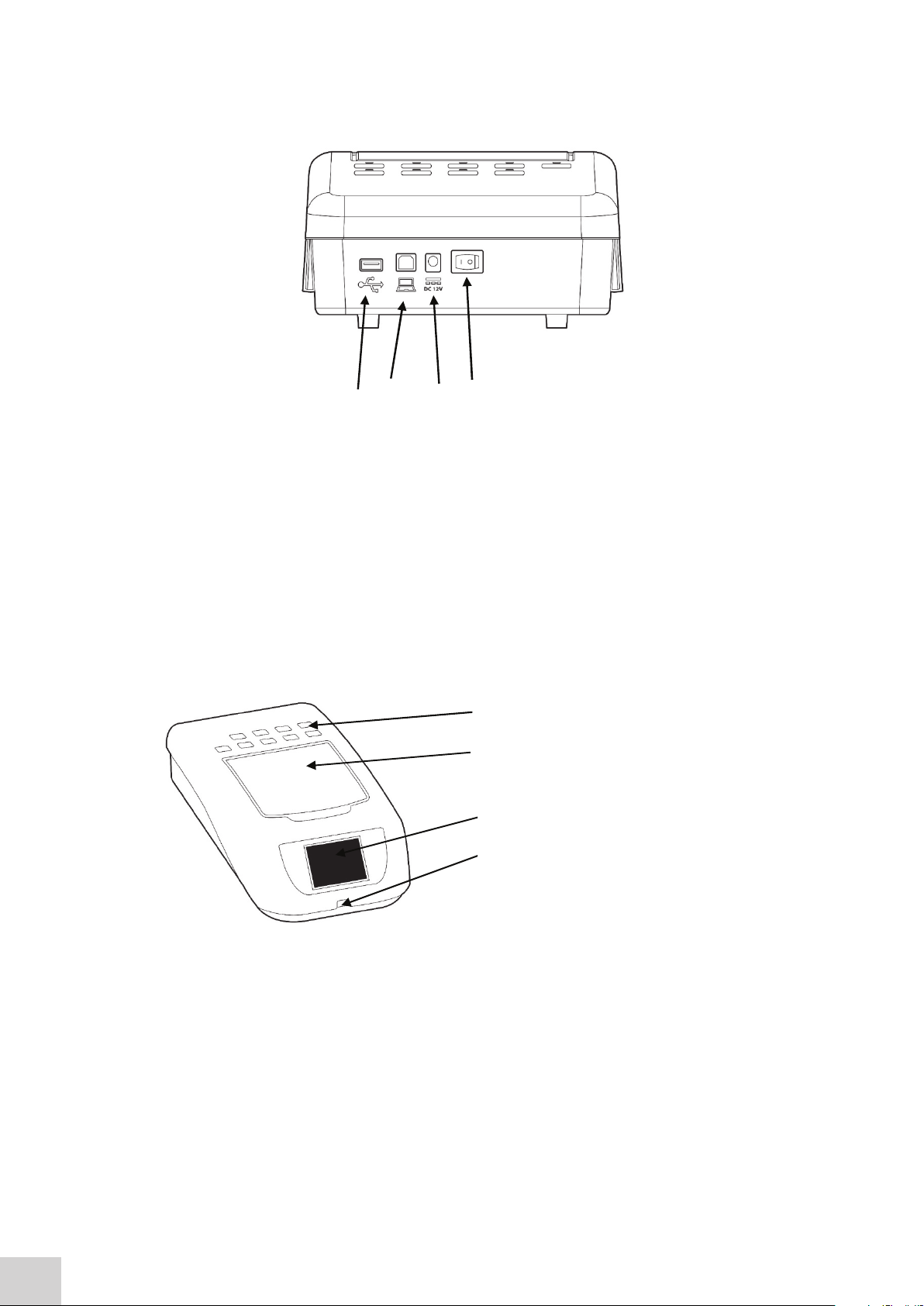
The image below shows the rear panel on the instrument:
Fig. 2.3.1 – Rear Panel
1. USB port Allows connection to a USB printer
2. PC connector Allows connection to a PC
3. Power in socket Connection socket for power supply unit
4. Rocker Switch Allows the unit to be powered on or off
1
4
3 2
1. Cuvette holders (10 x 10mm) For cuvette storage
2. Instrument lid Provides access to
sample chamber
3. Touchscreen Display User interface
4. USB memory stick slot Accepts USB stick
The image below shows the rear panel on the instrument:
Fig. 2.3.1 – Rear Panel
1. USB port Allows connection to a USB printer
2. PC connector Allows connection to a PC
3. Power in socket Connection socket for power supply unit
4. Rocker Switch Allows the unit to be powered on or off
2.4 FRONT PANEL
The image below shows the front panel of the instrument:
1. Cuvette holders (10 x 10mm) - For cuvette storage
2. Instrument lid - Provides access to sample chamber
3. Touchscreen Display - User interface
4. USB memory stick slot - Accepts USB stick
Fig. 2.4.1 – Front Panel
14
Page 15
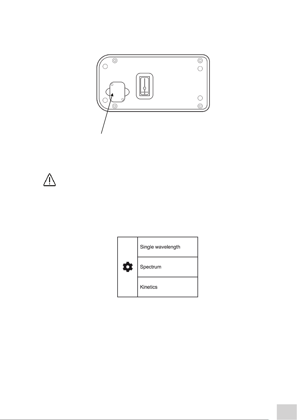
2.5 LAMP ACCESS PANEL
2.5 LAMP ACCESS PANEL
The image below shows the lamp access panel on the underside of the instrument:
Fig. 2.5.1 – Lamp Access Panel
1. Lamp Access Panel
Allows access to lamp when replacement is necessary
WARNING! Refer to section 10.2 for instructions on how to remove and replace the lamp.
1
The image below shows the lamp access panel on the underside of the instrument:
WARNING! Refer to section 10.2 for instructions on how to remove and replace the lamp.
2.6 DISPLAY
The instrument has a touchscreen display which enables easy setup and navigation of the instrument.
Fig. 2.6.1 – Main Screen
• Settings
• Single Wavelength Measurement Modes
• Spectrum Measurement Mode
• Kinetics Measurement Mode
15
Page 16
SECTION 3 – Theory and Practice of Spectroscopy Measurements
A = l c
-1cm-1
)
-1
)
I
t
Where:
I
o
is the incident light
l
t
is the transmitted light
is the path length
-1
)
is the incident light
3.1 THEORY OF SPECTROSCOPY MEASUREMENT
UV-visible spectroscopy is the measurement of the absorbance of light at a specific wavelength in a
sample. This is used to identify the presence and concentration of molecular entities within the sample.
The Beer-Lambert law is used to relate the absorption of light to the properties of the sample through
which the light is travelling through. The Beer-Lambert law states that:
A = l c
A is the absorbance
-1cm-1
is the molar absorption coefficient (l mol
c is the concentration (mol l
-1
)
)
l is the path length (cm)
This law shows that absorbance is linear to concentration but this is only true for low concentrations.
For absorbance levels above 3 the concentration starts to move away from the linear relationship.
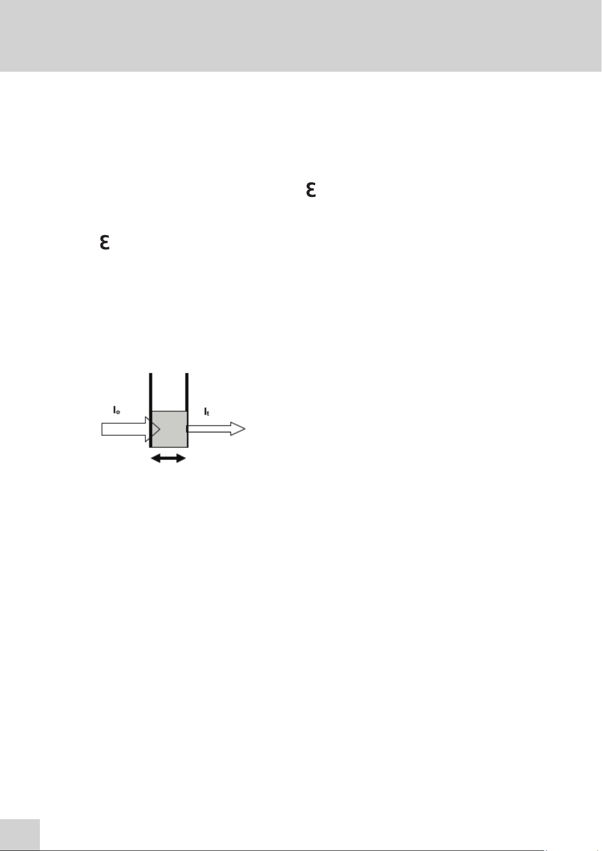
Transmittance is the proportion of the light which passes through the sample:
Where:
is the incident light
l
L
o
lt is the transmitted light
l is the path length
Therefore:
Absorbance is inversely related to transmittance:
16
Page 17
3.2 SPECTROSCOPY MEASUREMENT
There are four main components of a spectrophotometer. These are a light source to emit a high and
constant amount of energy over the full wavelength range, a sample holder, a method for separating
the light into discreet wavelengths and a light detector.
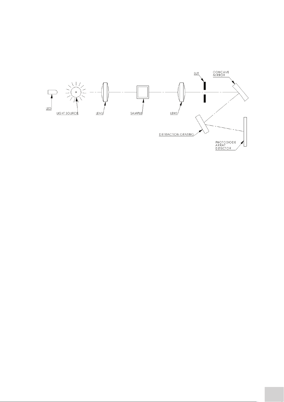
The optical layout of the 7200 spectrophotometer is shown below:
The whole light spectrum from the pre-aligned tungsten halogen lamp and the LED is collimated through
a lens and passed through the sample. The spectrum of light then passes through a further slit and
lens arrangement before being focussed onto the diffraction grating, which separates the light into
discrete wavelengths. The light which has not been absorbed by the sample is measured by the
photodiode array detector. The photo-diode array detector used is mounted directly onto the detector
PCB and the output is used to calculate the % transmittance. The result is displayed either as %
transmittance or absorbance on the instrument display.
3.3 GOOD PRACTICE GUIDELINES
1. For optimum performance all spectrophotometers should be sited in a clean, dry, dust free
atmosphere. When in use ambient temperature and light levels should remain as constant
as possible.
2. If required adherence to Standard Operating Procedures (SOP) and Good Laboratory
Practice (GLP) should be monitored with regular calibration checks and a suitable Quality
Control (QC) programme.
3. Ensure that there is nothing additional in the sample chamber which could block the light
path during calibration and sample measurement. Do not divert the light path using a
mirrored surface within the sample compartment.
Figure 3.2.1 – Diagram of light path
4. The correct selection of sample containers is imperative for accurate and reproducible
results:
a) Check that the material of the sample container is compatible with the wavelengths to
be used for measurement. In general glass can only be used down to 360nm or 320nm
depending on quality. Standard plastic cuvettes can be used down to 320nm. Special
UV versions can be used down to 260nm. Below this level quartz cuvettes must be
used.
b) Plastic disposable cuvettes should only be used ONCE.
17
Page 18

c) Glass cuvettes should be thoroughly cleaned after use. Discard when scratches become
evident on optical surfaces.
d) Care should be taken when selecting semi-micro or micro cuvettes. The cuvette window on
the inner chamber (the area filled with sample) must be wider than the aperture in the sample
holder or light will reach the detector without passing through the sample. In this case, semi micro or micro cuvettes with self-screening black surrounds must be used or, alternative
holders for these cuvettes should be used.
e) Glass test tubes and other sample tubes should be used with care. Where possible, matched
tubes should be used and any index mark set to the correct position before measurements
are made.
f) Ensure any sample containers used are compatible with the constituents of both the samples
and standards they are to hold. Plastic cuvettes are not compatible with organic solvents.
g) All sample containers must be handled with care; by the top, bottom and non-optical
surfaces only. Any finger marks evident must be removed by a suitable cleaning
process.
h) Flow-through cuvettes must be selected with care and consideration for the sample type,
sample volume, pumping system, rinse, sample and waste handling to be used.
5. Samples and standards should not be stored in open cuvettes or sample containers as
evaporation will change the value and lead to staining of the walls which may be irreversible.
If stored in stoppered and sealed cuvettes, they should be filled with little or no air space and the
values regularly checked against a reference standard or quality control material.
6. Samples should be allowed to equilibrate to ambient temperature before measurement (unless
a suitable temperature controlled sample holder is in use). Temperature change during
measurement may cause air bubbles to form on the walls of the sample holder. This is a common
cause of drift during measurement.
7. In the preparation of samples and standards high grade borosilicate glass and AR grade chemicals
and reagents must be used. Good quality deionised water or other suitable solvents must be used
for dissolving or diluting samples, chemicals and reagents.
8. All measurements require calibration to a blank, for maximum accuracy this should be prepared
with care using the same deionised water or solvent used for dissolving or diluting the sample.
Where reagents are added to the sample to produce a colour proportional to its concentration
a ‘sample based’ blank should be used. In this case the blank should consist of all reagents or
chemicals to be used, except the sample which will produce the colour to be measured.
9. Deviations from the Beer-Lambert Law may occur at high and low concentrations giving non-linear
response during sample concentration measurements. For all new methods a linear range should
be defined by the preparation of a calibration curve. The quantitation mode may be used to
construct such a curve against which sample results are automatically measured.
10. Cuvettes and sample holders must be filled to a minimum level which covers the light path.
All Jenway spectrophotometers have a beam height of 15mm.
11. The instrument must be calibrated to zero absorbance/100% transmittance prior to taking
readings. In the spectrum measurement mode a baseline scan must be performed before
performing a sample scan.
18
Page 19
SECTION 4 – Instrument Setup
4.1 NAVIGATING AND SCREEN SETUP
The main home screen is displayed below:
Model 7200 has a colour touchscreen user interface. To navigate around the spectrophotometer screen,
touch the icon or text which you want to action.
In every screen there is a back arrow which returns to the previous screen without saving any
changes.
In each measurement mode there is a home icon which returns immediately to the home screen.
4.2 INSTRUMENT SETTINGS SCREEN
The instrument settings screen is accessed by touching the instrument settings icon in the Home
Screen. This screen enables access to printing and saving options, heated cell accessory control,
setting date and time, language and software updates. Touch the down arrow to view the second
screen.
19
Page 20
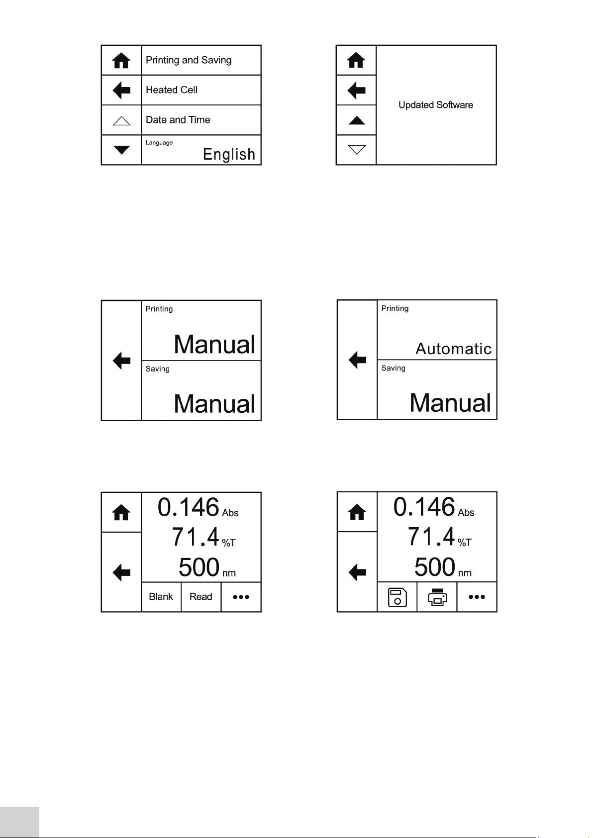
4.3 PRINTING AND SAVING
Printing (with the accessory printer) and saving (to a USB memory stick) can be performed manually in
each mode but for selected measurement modes it can also be set up be carried out automatically.
Automatic saving can only be done in the single measurement modes.
Touch Printing or Saving to toggle between Manual and Automatic.
To print or save manually in any measurement mode, touch the overflow icon button at the bottom of
the screen.
20
Touching the overflow icon displays the options for manual printing or manual saving. Touch the save
icon to save the result to USB memeory stick. If a USB memory stick is not inserted an error message
will be displayed. Touch the print icon to print the results using an external printer. If the printer is not
connected, switched on or out of paper an error message will be displayed. Touching the overflow
icon
Page 21
icon once again will cycle the screen back to the previous view, allowing blank and sample measurements
to be performed.
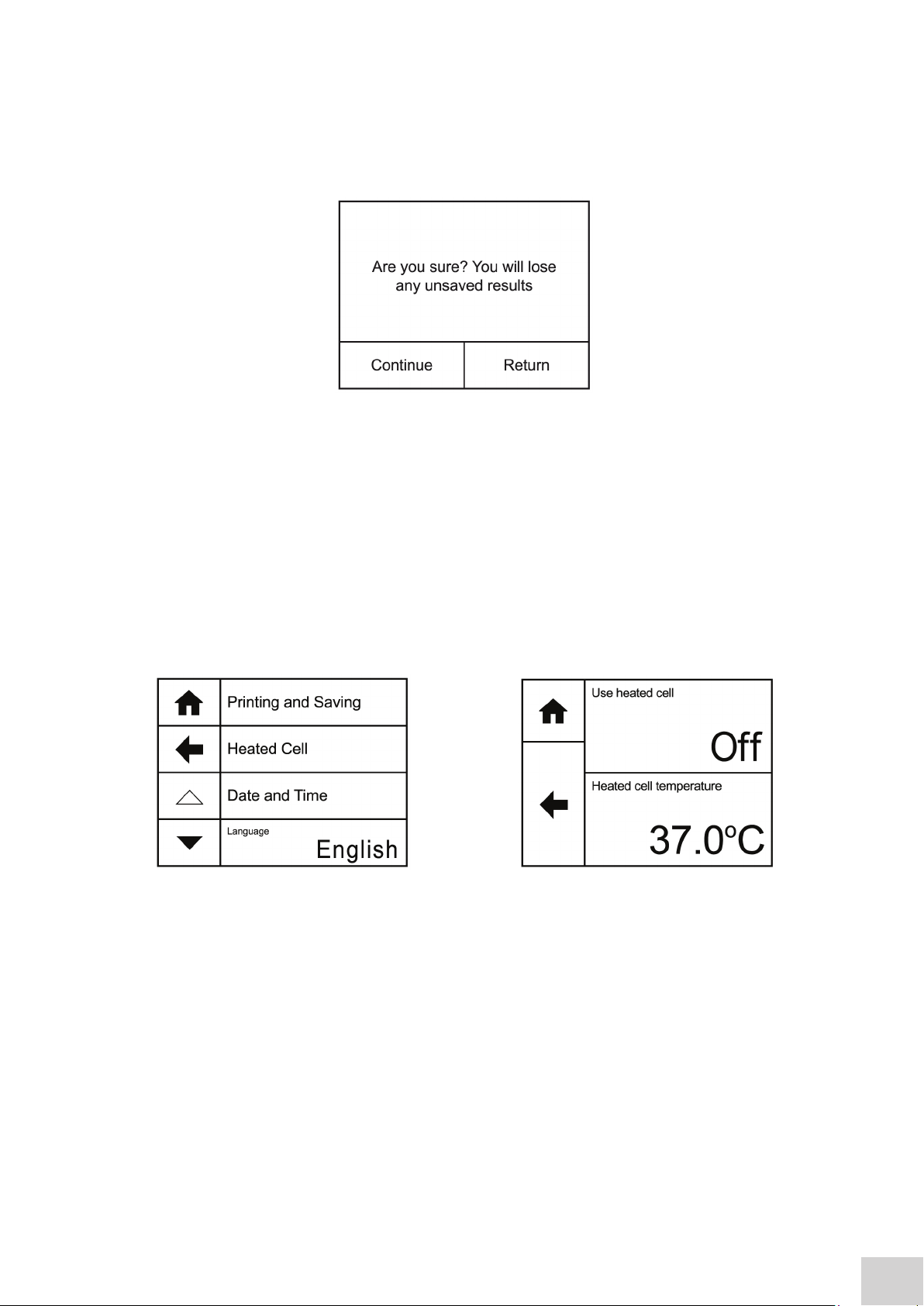
Once a sample reading has been performed if the results are not saved to USB memory stick a warning
message will be displayed when the mode is exited by pressing the Home icon.
Touch Continue to exit the measurement mode and the results will not be saved. Touch Return to
return to the measurement mode so that the results can be saved.
4.4 HEATED CELL ACCESSORY CONTROL
A heated 10x10mm cuvette holder is available as an optional accessory for Model 7200. This accessory
enables the temperature of the sample to be adjusted. To set up the parameters of the heated cell
accessory, touch Heated Cell in the Settings screen. Touch Use Heated Cell to toggle between Off and
On.
To adjust the temperature of the heated cell, touch Heated Cell Temperature. Touch the up or down
arrows to increase or decrease the set temperature in 0.5°C increments. The minimum temperature is
32°C, the maximum temperature is 42°C. Touch OK to confirm or touch the back arrow to return to
the previous screen without saving any changes. Please note that the heated cell takes approximately 30
mins to heat a 2.5ml sample to 37°C.
21
Page 22

4.5 DATE AND TIME
The time and date screen enables the current time and date to be set. This information will be saved on
all results and displayed on printouts.
To adjust the date touch Date and use the arrow
icons to increase or decrease the number. Touch
OK to confirm or touch the back arrow to return to
the previous screen without saving any changes.
22
To adjust the time touch Time and use the arrow
icons to increase or decrease the number. Touch
OK to confirm or touch the back arrow to return to
the previous screen without saving any changes.
Page 23

The date format can be displayed as either European format dd/mm/yy or American format mm/dd/yy
by touching Date Format. To display the time as either a 12 hour clock or a 24 clock touch Time
Format.
4.6 LANGUAGE
The 7200 operating software can also be displayed
in French. To select the required language touch
Language. The software will change into French
language. To return to English touch Langue. The
language selected will also be displayed on the
printouts. The selected language when the
instrument is switched off will be loaded when the
instrument is turned on.
4.7 SOFTWARE UPDATE
Update Software
The 7200 operating software can be updated via
USB memory stick. The update must first be
downloaded to a USB memory stick from the
Jenway website. Insert a USB device into the USB
port on the front of the instrument and navigate to
the Update Software option in the settings screen.
Touch Update Software to begin the update.
If there is no USB memory stick inserted
the above screen will be shown.
If there is no update file on the USB
memory stick the above screen will be
shown.
23
Page 24

If there is a valid update file on the USB memory
stick, then Load Software becomes active.
Touch Load Software to start the upload process.
Touch Update to begin installing the new
software.
At the end of Part 5 of 5, the instrument will restart
and the bootloader will perform the update.
Once the update is completed touch Continue to
complete the update process.
24
Page 25

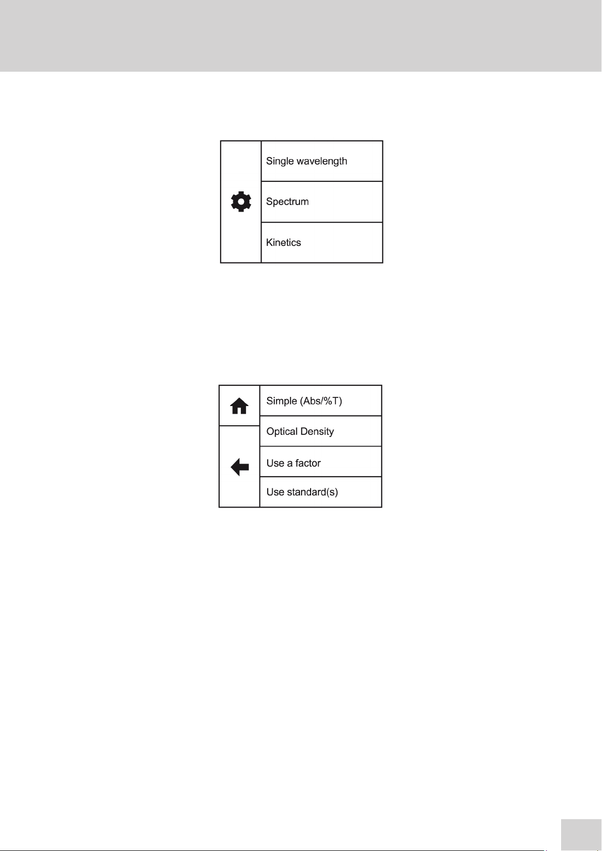
SECTION 5 – Single Wavelength
The single wavelength measurement mode provides options to measure simple absorbance and %
transmittance, optical density and concentration using a factor, single standard or quantitation curve.
Touch Simple Wavelength to display the different measurement modes:
Simple (Abs/%T)
This option allows simple measurements of absorbance or % transmittance to be performed.
Optical Density
Optical density measurement mode enables optical density measurements of cell cultures and broths
to be performed. In this mode, it is possible to use a known factor to estimate the number of cells
present.
Use a factor
This measurement mode enables concentration measurements to be performed. It is possible to use a
known factor to determine the concentration of a solution based on the measured absorbance.
Use standard(s)
This mode enables sample concentrations to be calculated using a standard curve or a single standard.
In this mode, a number of standard solutions covering a range of known concentrations are measured
at a set wavelength. The absorbance or % transmittance of these solutions are plotted to create a
standard curve with replicate standard measurements, if required. Once the standard curve has been
created, a sample of unknown concentration can be measured and the concentration calculated using
the standard curve. If only one standard is available the instrument will subsequently calculate the factor
which can be used to calculate the unknown concentration.
25
Page 26

5.1 SIMPLE (ABS/%T) MEASUREMENT MODE
5.1.1 Method Setup
Simple (Abs/%T) enables simple measurements of
absorbance and % transmittance to be performed.
The sample is measured at every wavelength but
only the result for the selected wavelength is
displayed. There are no post measurement
calculations available in this measurement mode.
Touch Simple (Abs/%T) to enter this measurement
mode and begin method setup.
The method parameters which can be selected are
the wavelength and the measurement name. Once
these have been entered touch the forwards arrow
to enter the measurement screen. The back arrow
will return to the previous screen and the home icon
will return to the home screen. Neither of these
options will save any parameters entered.
5.1.2 Selecting a Wavelength
Touch Wavelength (nm) to enter the required wavelength. Either type the wavelength required using
the numeric keypad or touch delete to clear the screen and then type in the wavelength. Touch OK to
confirm and save or touch the back arrow to return to the previous screen without saving the entered
wavelength.
26
Page 27

5.1.3 Measurement Name
Touch Measurement Name to enter the required name for the sample. This name will be used to
identify the result on any printouts or if the result is saved to USB memory stick. Either type the name
required using the alphanumeric keypad or touch delete to clear the screen and then type in the
name.
Please note the name is restricted to a maximum of 8 characters. Touch OK to confirm and save or
touch the back arrow to return to the previous screen without saving the entered name. The ABC icon
will toggle between alpha and numeric options.
5.1.4 BLANK CALIBRATION AND SAMPLE MEASUREMENT
A blank calibration must be performed before a sample can be measured. Insert a cuvette containing
the blank solution into the sample chamber. Touch Blank and the instrument will perform a zero
absorbance and 100% transmittance reading.
Once the blank calibration is complete Read becomes active and the sample can be measured. As
the spectrophotometer measures the entire wavelength range in one scan, if the wavelength is
adjusted before a sample is measured the instrument doesn’t need be calibrated again at the new
wavelength.
27
Page 28

Remove the cuvette containing the blank solution and place a cuvette containing the sample to be
measured in the sample holder. Touch Read to measure the sample. Once the measurement is
complete the photometric result will be shown on the screen. Subsequent samples can be measured
in the same way.
To adjust the wavelength there is no need to return to the method setup. Touch the screen to open
the adjustment screen. Touch the arrow icons to increase or decrease the wavelength. The
photometrics result will be adjusted accordingly. Touch the back arrow to return to the measurement
screen and the adjusted results will be displayed on the screen.
5.2 OPTICAL DENSITY MEASUREMENT MODE
The OD 600 measurement mode enables optical density measurements of cell cultures and broths to
be performed. In this measurement mode it is possible to use a known factor to estimate the number of
cells. There are no post measurement calculations available in this measurement mode. Touch Optical
Density to enter this measurement mode and begin method setup.
5.2.1 Method Setup
The method parameters which can be
selected are the wavelength, the
measurement name, the factor and the
concentration units. Once these have been
entered touch the forwards arrow to enter
the measurement screen. The back arrow
will return to the previous screen and the
home icon will return to the home screen.
Neither of these options will save any
parameters entered.
28
Page 29

5.2.2 Selecting a Wavelength
Touch Wavelength (nm) to enter the required wavelength. Either type the wavelength required using
the numeric keypad or touch delete to clear the screen and then type in the wavelength. Touch OK to
confirm and save or touch the back arrow to return to the previous screen without saving the entered
wavelength.
5.2.3 Measurement Name
Touch Measurement Name to enter the required name for the sample. This name will be used to
identify the result on any printouts or if the result is saved to USB memory stick. Either type the name
required using the alphanumeric keypad or touch delete to clear the screen and then type in the
name.
Please note the name is restricted to a maximum of 8 characters. Touch OK to confirm and save or
touch the back arrow to return to the previous screen without saving the entered name. The ABC icon
will toggle between alpha and numeric options.
5.2.4 Entering a factor
Touch Factor to enter the required factor.
The minimum factor which can be entered is
-1000, the maximum factor which can be
entered is +1000. Either type the factor
required using the numeric keypad or touch
delete to clear the screen and then type in
the factor. Touch OK to confirm and save or
touch the back arrow to return to the
previous screen without saving the entered
factor.
29
Page 30

5.2.5 Entering concentration units
The standard units of measure for optical
density is cells/ml but these can be adjusted
depending on requirements. Touch Units to
adjust the concentration units. Please note
that this is just a text field and changing within
a unit family e.g. mg/l and g/l will not change
the concentration result.
Either type the units required using the alphanumeric keypad or touch delete to clear the screen and
then type in the units. Please note the units are restricted to a maximum of 8 characters. Touch OK
to confirm and save or touch the back arrow to return to the previous screen without saving the
entered units. The 123 icon will toggle between alpha and numeric options.
5.2.6 BLANK CALIBRATION AND SAMPLE MEASUREMENT
A blank calibration must be performed before a sample can be measured. Insert a cuvette containing
the blank solution into the sample chamber. Touch Blank and the instrument will perform a zero
absorbance and 100% transmittance reading.
Once the blank calibration is complete Read becomes active and the sample can be measured. As
the spectrophotometer measures the entire wavelength range in one scan, if the wavelength is
adjusted before a sample is measured the instrument doesn’t need to be calibrated again at the new
wavelength.
30
Page 31

Remove the cuvette containing the blank solution and place a cuvette containing the sample to be
measured in the sample holder. Touch Read to measure the sample. Once the measurement is
complete the result will be shown on the screen. Subsequent samples can be measured in the same
way.
To adjust the wavelength there is no need to return to the method setup. Touch the screen to open
the adjustment screen. Touch the arrow icons to increase or decrease the wavelength. The result
will be adjusted accordingly. Touch the back arrow to return to the measurement screen and the
adjusted results will be displayed on the screen.
5.3 USE A FACTOR MEASUREMENT MODE
The Use a factor measurement mode enables concentration measurements to be performed. In this
measurement mode it is possible to use a known factor to determine the concentration of a solution
based on the measured absorbance:
Concentration = Factor x Absorbance
If the factor isn’t known then the Use Standard(s) measurement mode must be used to calculate
concentration. Touch Use A Factor to enter this measurement mode and begin method setup.
31
Page 32

5.3.1 Method Setup
5.3.2 Selecting a Wavelength
Touch Wavelength (nm) to enter the required wavelength. Either type the wavelength required using
the numeric keypad or touch delete to clear the screen and then type in the wavelength. Touch OK to
confirm and save or touch the back arrow to return to the previous screen without saving the entered
wavelength.
The method parameters which can be selected are
the wavelength, the measurement name, the factor
and the concentration units. Once these have
been entered touch the forwards arrow to enter
the measurement screen. The back arrow will
return to the previous screen and the home icon
will return to the home screen. Neither of these
options will save any parameters entered.
5.3.3 Measurement Name
Touch Measurement Name to enter the required name for the sample. This name will be used to
identify the result on any printouts or if the result is saved to USB memory stick. Either type the name
required using the alphanumeric keypad or touch delete to clear the screen and then type in the
name.
Please note the name is restricted to a maximum of 8 characters. Touch OK to confirm and save or
touch the back arrow to return to the previous screen without saving the entered name. The ABC icon
will toggle between alpha and numeric options.
32
Page 33

5.3.4 Entering a factor
5.3.5 Units of measure
mg/l
Touch Factor to enter the required factor.
The minimum factor which can be entered is
-1000, the maximum factor which can be
entered is +1000. Either type the factor
required using the numeric keypad or touch
delete to clear the screen and then type in
the factor. Touch OK to confirm and save or
touch the back arrow to return to the
previous screen without saving the entered
factor.
Touch Units to adjust the concentration units.
Please note that this is just a text field and
changing within a unit family e.g. mg/l and g/l
will not change the concentration result.
Either type the units required using the alphanumeric keypad or touch delete to clear the screen and
then type in the units. Please note the units are restricted to a maximum of 8 characters. Touch OK
to confirm and save or touch the back arrow to return to the previous screen without saving the
entered units. The 123 icon will toggle between alpha and numeric options.
5.3.6 BLANK CALIBRATION AND SAMPLE MEASUREMENT
A blank calibration must be performed before a sample can be measured. Insert a cuvette containing
the blank solution into the sample chamber. Touch Blank and the instrument will perform a zero
absorbance and 100% transmittance reading.
33
Page 34

100.0
Once the blank calibration is complete Read becomes active and the sample can be measured. As
the spectrophotometer measures the entire wavelength range in one scan, if the wavelength is
adjusted before a sample is measured the instrument doesn’t need be calibrated again at the new
wavelength.
Remove the cuvette containing the blank solution and place a cuvette containing the sample to be
measured in the sample holder. Touch Read to measure the sample. Once the measurement is
complete the result will be shown on the screen. Subsequent samples can be measured in the same
way.
To adjust the wavelength there is no need to return to the method setup. Touch the screen to open
the adjustment screen. Touch the arrow icons to increase or decrease the wavelength. The result
will be adjusted accordingly. Touching the back arrow to return to the measurement screen and the
adjusted results will be displayed on the screen.
34
Page 35

5.4 USE STANDARD(S) MEASUREMENT MODE
The use standard(s) measurement mode enables sample concentration to be calculated using a
standard curve or a single standard of known concentration. In this mode a number of standard
solutions covering a range of known concentrations are measured at a set wavelength. The
absorbance or % transmittance of these solutions is plotted to create a standard curve with replicate
standards measurements, if required. Once the standard curve has been created a sample of unknown
concentration can be measured and the concentration calculated using the standard curve.
If there is only one standard available this measurement mode will calculate the factor and use that to
calculate the concentration.
Touch Use Standard(s) to enter this measurement mode and begin method setup.
5.4.1 Method Setup
The method parameters enable the creation of a standard curve or a previously created standard curve
can be opened to measure unknown samples against.
The method parameters which can be adjusted are the wavelength, the measurement name, the units
of measure, the number of known standards and the number of replicates. Once these have been
entered touch the forwards arrow to enter the measurement screen. The back arrow will return to the
previous screen and the home icon will return to the home screen. Neither of these options will save
any parameters entered.
35
Page 36

5.4.2 Selecting a Wavelength
Touch Wavelength (nm) to enter the required wavelength. Either type the wavelength required using
the numeric keypad or touch delete to clear the screen and then type in the wavelength. Touch OK to
confirm and save or touch the back arrow to return to the previous screen without saving the entered
wavelength.
5.4.3 Measurement Name
Touch Measurement Name to enter the required name for the sample. This name will be used to
identify the result on any printouts or if the result is saved to USB memory stick. Either type the name
required using the alphanumeric keypad or touch delete to clear the screen and then type in the
name.
Please note the name is restricted to a maximum of 8 characters. Touch OK to confirm and save or
touch the back arrow to return to the previous screen without saving the entered name. The ABC icon
will toggle between alpha and numeric options.
5.4.4 Entering Concentration Units
mg/l
Touch Units to adjust the concentration units.
Please note that this is just a text field and
changing within a unit family e.g. mg/l and g/l
will not change the concentration result.
36
Either type the units required using the alphanumeric keypad or touch delete to clear the screen and
then type in the units. Please note the units are restricted to a maximum of 8 characters. Touch OK to
confirm and save or touch the back arrow to return to the previous screen without saving the entered
units. The 123 icon will toggle between alpha and numeric options.
Page 37

5.4.5 Selecting the Number of Standards and Replicates
The number of standards used can be changed between 1 and 6. If 1 is selected then a calibration
curve will not be created. Touch the number of standards required and touch the back arrow to return
to method setup.
Each standard can have up to 3 replicate measurements performed. If more than 1 replicate is selected
the instrument will take the average absorbance value of the replicates measured to construct the
calibration curve. Touch the number required and touch the back arrow to return to method setup.
5.4.6 Measuring Standards
Before the concentration of each known standard can
be measured a blank calibration must be performed.
Insert the cuvette containing the blank solution and
touch Press to perform blank.
The concentration of each known standard must be
entered before it is measured. Touch Set Standard 1
and use the number entry screen to enter the
concentration of the standard. Touch OK to confirm
and save or press the back arrow to return to the
measure standards screen without saving the
concentration.
37
Page 38

Insert the cuvette containing standard 1 and touch
Replicate 1. The instrument will perform a reading
and display the absorbance result. If more than one
replicate has been selected, touch Replicate 2 to
perform the second reading. Repeat if necessary for 3
replicates. Touch the forwards arrow to measure the
next standard.
If only 1 standard has been selected then the factor
will be displayed. This factor can be used to calculate
the concentration of the unknown sample.
If more than 1 standard has been selected each
additional standard must be measured in the same
way. Touch Set Standard 2 and use the number entry
screen to enter the concentration of the standard.
Touch OK to confirm and save or press the back
arrow to return to the measure standards screen
without saving the concentration. Insert the cuvette
containing standard 2 and touch Replicate 1.
The instrument will perform a reading and display the absorbance result. Touch the forwards arrow
to measure the next standard or display the calibration curve if only 2 standards have been selected.
Once all the standards have been measured the
calibration curve will be displayed. Touch Current
Curve Fit to toggle between linear or linear through
zero.
Linear: Concentration = Abs x A + B
Linear through zero: Concentration = Abs x A
38
Where: gradient of the line (A), constant (B) and
correlation coefficient (r2).
Touch save to save the standard curve to USB memory stick. If there isn’t a USB memory stick
inserted a warning will be displayed.
Page 39

Touch the forwards arrow to enter the measurement screen.
Touch Standard Curve Name to enter the required
name for the curve. This name will be used to identify
the curve on the USB memory stick. Either type the
name required using the alphanumeric keypad or
touch delete to clear the screen and then type in the
name. Please note the name is restricted to a
maximum of 8 characters. Touch OK to confirm and
remember the entered name or touch the back arrow
to return to the previous screen without remembering
the entered name. The ABC icon will toggle between
alpha and numeric options.
Touch OK to confirm and save or touch the back arrow to return to the previous screen without
saving the entered name. If the curve has been saved the instrument will display confirmation.
Touch the forwards arrow to enter the measurement screen.
5.4.7 Load Standard Curve
It is not necessary to create a new standard curve each time an unknown sample needs to be
measured. Ensure the USB memory stick is inserted into the instrument. Touch Load A Standard
Curve and a list of previously saved standard curves will be displayed. Touch the up or down arrows
to display more results on the screen. The files are saved in date and time order from most recent to
oldest. Touch the name of the required curve and the standard curve will automatically be loaded.
To return to the previous screen without loading a standard curve touch the back arrow.
39
Page 40

Touch the forwards arrow to enter the measurement screen.
To delete a standard curve from the USB memory stick touch delete. Touch the name(s) of the curve
to be deleted. To deselect a curve touch the name of the curve again. Touch OK to confirm or touch
the back arrow to return to the previous screen without loading or deleting any standard curves.
If there are no standard curves saved to the USB
memory stick an error message will be displayed.
5.5 BLANK CALIBRATION AND SAMPLE MEASUREMENT
A blank calibration must be performed before a sample can be measured. Insert a cuvette containing
the blank solution into the sample chamber. Touch Blank and the instrument will perform a zero
absorbance and 100% transmittance reading.
100.0
40
Once the blank calibration is complete Read becomes active and the sample can be measured.
Page 41

Remove the cuvette containing the blank solution and place a cuvette containing the sample to be
measured in the sample holder. Touch Read to measure the sample. Once the measurement is complete
the result will be shown on the screen. Subsequent samples can be measured in the same way.
Although this spectrophotometer measures the entire wavelength range in one scan if the wavelength
needs to be adjusted a new calibration curve must be created at the new wavelength.
41
Page 42

SECTION 6 – Spectrum
The spectrum measurement mode enables measurements of absorbance or % transmittance over a
range of wavelengths to be performed. The absorbance or % transmittance at each wavelength is
plotted graphically. Post measurement tools such as spectral points analysis can be performed. This
operating mode can be used to partially characterise a sample. Touch Spectrum to enter this
measurement mode and begin method setup.
6.1 METHOD SETUP
The method parameters which can be selected are,
the measurement name, the measurement mode
and the start and end wavelengths. Once these
have been entered touch the forwards arrow to
enter the measurement screen. The back arrow will
return to the previous screen and the home icon will
return to the home screen. Neither of these options
will save any parameters entered.
800
6.1.1 Measurement Name
Touch Measurement Name to enter the required name for the sample. This name will be used to
identify the result on any printouts or if the result is saved to USB memory stick. Either type the
name required using the alphanumeric keypad or touch delete to clear the screen and then type in
the name. Please note the name is restricted to a maximum of 8 characters. Touch OK to confirm
and save or touch the back arrow to return to the previous screen without saving the entered name.
The ABC icon will toggle between alpha and numeric options.
42
Page 43

6.1.2 Selecting Measurement Mode
The measurement mode can be user selected between absorbance and % transmittance. Touch
Measurement Mode to cycle between the two options.
6.1.3 Setting Start and End Wavelengths
This function enables the start and end wavelengths of the spectrum scan to be set. The 7200 has
a spectrum range from 335 to 800nm and measures the entire wavelength range simultaneously.
However the user can select the wavelength range which is displayed. Following the measurement
the start and end wavelengths can be adjusted and the spectrum across the new wavelength range
will be displayed.
Touch Start Wavelength or End Wavelength to
enter the required wavelength. Either type the
wavelength required using the numeric keypad or
touch delete to clear the screen and then type in
the wavelength. Touch OK to confirm and save or
touch the back arrow to return to the previous
screen without saving the entered wavelength.
The start wavelength must be smaller than the
end wavelength.
Wavelength(s) cannot
be the same
Once the required wavelengths have been
entered touch the forwards arrow to move into
the measurement screen. If the start and end
wavelengths entered are equal, the instrument
will display a short warning before returning back
to the parameters screen to allow further editing.
If the start wavelength is above the end wavelength
a warning will be displayed.
Touch Swap Values to simply swap the start and
end wavelengths and continue. Touch Go Back
to edit the start and end wavelengths.
Once all the parameters have been measured touch the forward arrow to enter the measurement
screen.
43
Page 44

6.2 BLANK CALIBRATION AND SAMPLE MEASUREMENT
A blank calibration must be performed before a
sample can be measured. Insert a cuvette
containing the blank solution into the sample
chamber. Touch Blank and the instrument will
before a baseline calibration.
Once the baseline has been completed Read becomes active and the sample can be measured.
Remove the blank cuvette containing the blank solution and place a cuvette containing the sample
to be measured into the sample holder. Touch Read to measure the sample.
As the entire wavelength range is measured simultaneously it is not possible to view a live spectrum
scan as the wavelengths are not measured one at a time. Once the measurement is complete the
spectrum scan will be displayed on the screen and the post measurement tools icon will become
active.
44
Page 45

6.3 DATA ANALYSIS
Once a measurement has been completed the post measurement tools icon becomes active. Touch
the post measurement tool icon to open tools screen. This enables access to the zoom function
and the spectral points analysis function.
The zoom function enables areas of interest on the spectrum to be magnified. The spectral points
analysis function enables points to be selected from the scan to analyse absorbance or %
transmittance at selected wavelengths.
6.3.1 Spectrum Zoom
Touch the zoom icon to open the zoom screen. When
the spectrum zoom mode is first entered, only Zoom
in is enabled. Zoom Out, Zoom Left and Zoom Right
are only available once the display is showing a
zoomed in part of the scan rather than a full scan. To
zoom in on a particular section of the scan, either
touch the scan on the required part or touch Zoom In
to zoom in centrally on the displayed portion of the
scan.
The zoom bar at the top of the screen indicates both how far the scan is zoomed in and over which
portion of the original scan the zoomed in portion is from – this is indicated by the white portion of the
bar.
Touch the Zoom In icon to increase magnification or touch the Zoom Left or Zoom Right arrows
to move the magnification to a different part of the spectrum. Touch Zoom Out to return to the
original spectrum scan.
Touch the back arrow to return to the previous screen.
45
Page 46

6.3.2 Spectral Points Analysis
The spectral points analysis function enables
points to be selected from the scan to analyse
the absorbance or % transmittance at a selected
wavelength. Touch spectral points analysis to
open the selection screen.
A solid vertical line will appear on the screen. The
position of the line can be moved by touching the
arrow icons or by touching the screen. The
values at the top of the screen display the
wavelength and photometrics result for that
point. When the required point is selected touch
add to table icon and the selected point will be
added to the table. Once the point has been
added it will be marked on the spectrum. Up to
50 points can be added to the table.
To delete all the points from the spectral points analysis table touch delete and all previously
selected points will be deleted.
To view the points in the spectral points analysis
table touch the table icon. The selected points
will be displayed along with the absorbance or %
transmittance depending on the measurement
mode selected in the method setup. The results
will be displayed in numerical order from smallest
to largest.
To view points not displayed on the screen touch
the up or down arrows.
Touch Print to print the spectral analysis points table. An error message will be displayed if an
external printer is not connected or switched on.
46
Failed to send
data to printer
Page 47

SECTION 7 – Kinetics
The kinetics measurement mode enables the absorbance or % transmittance of an active molecule
to be measured over a period of time. For example, enzyme analysis of horseradish peroxidase. The
absorbance or % transmittance is measured at regular time intervals at a set wavelength over a period
of time. The results are plotted on a graph to show the change in absorbance or % transmittance over
time. Touch Kinetics to enter this measurement mode and begin method setup.
7.1 METHOD SETUP
The parameters which can be selected are the measurement name, the number of wavelengths, the
measurement mode, run time, lag time and end point concentration units. Once these have been
entered touch the forwards arrow to enter the measurement screen. The back arrow will return to
the previous screen and the home icon will return to the home screen. Neither of these options will
save any parameters entered.
7.1.1 Measurement Name
Touch Measurement Name to enter the required name for the sample. This name will be used to
identify the result on any printouts or if the result is saved to USB memory stick. Either type the name
required using the alphanumeric keypad or touch delete to clear the screen and then type in the
name. Please note the name is restricted to a maximum of 8 characters. Touch OK to confirm and
save or touch the back arrow to return to the previous screen without saving the entered name.
The ABC icon will toggle between alpha and numeric options.
47
Page 48

7.1.2 Selecting Number of Wavelengths
Touch Number of Wavelengths to select the required number of wavelengths. Touch 1, 2 or 3 to
select the required number of wavelengths to measure the change in absorbance or % transmittance
over time.
7.1.3 Selecting Measurement Mode
The measurement mode can be user selected between absorbance and % transmittance. Touch
Measurement Mode to cycle between the two options.
7.1.4 Run Time
Touch Run Time (Seconds) to enter the total run time for the kinetics experiment. Either type the
time required using the numeric keypad or touch delete to clear the screen and then type in the time.
Touch OK to confirm and save or touch the back arrow to return to the previous screen without
saving the entered time. The minimum run time is 15 seconds, the maximum run time is 9999
seconds. Due to the size of the instrument memory the instrument can only store 100 measurement
points per wavelength. Depending on the run time entered the instrument will calculate the minimum
measurement interval, subject to a minimum interval of 15 seconds.
7.1.5 Lag time (Seconds)
Seconds
60
48
Touch Lag Time (Seconds) to enter the number of seconds that the instrument waits before
commencing measurements after Read has been touched in the measurement screen. Either type
the time required using the numeric keypad or touch delete to clear the screen and then type in the
time. Touch OK to confirm and save or touch the back arrow to return to the previous screen
without saving the entered time. The minimum lag time is 0 seconds, the maximum lag time is 999
seconds.
Page 49

7.1.6 Selecting Concentration Units
At the end of the kinetics run the concentration of the sample can be calculated using the end point
absorbance value:
Concentration = Factor x absorbance
The units of concentration can be entered here and will appear in the result screen after completion of
the kinetics run.
Touch Units to enter the required concentration units. Either type the units required using the
alphanumeric keypad or touch delete to clear the screen and then type in the units. Please note the
units are restricted to a maximum of 11 characters. Touch OK to confirm and save or touch the back
arrow to return to the previous screen without saving the entered units. The 123 icon will toggle
between alpha and numeric options.
mg/l
7.1.7 Selecting a Wavelength and Factor
The wavelength and factor for each wavelength selected will need to be entered.
Touch Set Wavelength 1 to enter the required wavelength. Either type the wavelength required using
the numeric keypad or touch delete to clear the screen and then type in the wavelength. Touch OK to
confirm and save or touch the back arrow to return to the previous screen without saving the entered
wavelength.
At the end of the kinetics run the concentration of the sample can be calculated using the end point
absorbance value:
Concentration = Factor x absorbance
Touch Endpoint Factor to enter the required factor to calculate the concentration. Either type the
factor required using the numeric keypad or touch delete to clear the screen and then type in the
factor. Touch OK to confirm and save or touch the back arrow to return to the previous screen
without saving the entered factor. If you do not require the concentration to be calculated leave the
factor as a default of 1. The minimum factor which can be entered is -1000, the maximum factor
which can be entered is +1000.
49
Page 50

Once the parameters for wavelength 1 have been entered, touch the forwards arrow to enter the
wavelength and end point factor for wavelengths 2 and 3 (if selected), or to enter the measurement
mode.
7.2 BLANK CALIBRATION AND SAMPLE MEASUREMENT
A blank calibration must be performed before a sample can be measured. Insert a cuvette containing
the blank solution into the sample chamber. Touch Blank and the instrument will perform a zero
absorbance and 100% transmittance reading.
Once the blank calibration is complete Read becomes active and the sample can be measured. As the
spectrophotometer measures the entire wavelength range in one scan, if the selected wavelength(s)
are adjusted before a sample is measured the instrument doesn’t need be calibrated again at the new
wavelength(s).
Remove the cuvette containing the blank solution and place a cuvette containing the sample to be
measured in the sample holder. Touch Read to measure the sample.
During the kinetics run the full run time in minutes will be displayed in the bottom right hand corner
of the measurement screen. Touch Run Time to toggle the display between showing the total elapsed
time of the kinetics run or showing the measurement interval count down to the next measurement
being taken.
50
Page 51

When the instrument is not taking a
measurement the kinetics run can be stopped
by touching Stop. Whilst a measurement is
being taken, Stop is replaced by the waiting
indicator and the button is temporarily inactive
to touches.
If a lag time was entered during method set
up the instrument will count down the lag time
before it begins taking measurements. To
stop the lag time count down touch Stop.
Once the measurement is complete the Post
Measurement icon becomes active.
Subsequent samples can be measured in the
same way.
7.3 Post Measurement Analysis
Once the kinetics run is complete it is possible
to view the endpoint concentration at each
selected wavelength. Touch the Post
Measurement icon to display the information.
Touch the wavelength to move through the
selected wavelengths or touch the backwards
arrow to return to the measurement screen.
51
Page 52

SECTION 8 – Glossary of Icons
Icon Description
Back Arrow – return to previous screen
Forwards Arrow – move to next screen
Home – returns to home screen
Instrument Settings – access to instrument settings
Print – to send results to an external printer
Save – to save results to a USB memory stick
Overflow – to toggle display between Blank/Read and Save /Print
Up Arrow - to move up or increase
Down Arrow - to move down or decrease
OK
Delete – to delete entry
Space – used when naming results or standard curves
ABC
123
OK - to confirm
ABC – toggles between alpha and numeric keypads
123 – toggles between alpha and numeric keypads
52
Standard curve selected for deletion
Post measurement analysis tool for spectrum
Page 53

Icon Description
Spectral zoom
Zoom In
Zoom Out
Zoom to the right (spectrum)
Zoom to the left (spectrum)
Spectral points analysis
Add Spectral point to table
Delete all spectral analysis points or delete selected standard curves
Table – view selected spectral analysis points
Post measurement analysis tool for kinetics
53
Page 54

SECTION 9 – Accessories and Spare Parts
9.1 OPTIONAL ACCESSORIES
Part Code Description of Accessory
SMP50/PRINTER External printer
630 204 10 x 10mm path length cuvette holder
637 071 16/24mm test tube holder
630 005 10 to 100mm path length cuvette holder
630 304 Micro-cuvette holder with reduced aperture
019 148 4GB USB memory sticks for external memory
060 084 Pack of 100 disposable cuvettes (visible)
700 000 Dust Cover
9.2 CONNECTING THE ACCESSORIES
There are two types of accessories which can be fitted in the sample chamber – passive (nonpowered)
or active (powered) accessories. The range of passive accessories includes 10 x 10mm single cuvette
holder, adjustable path length (10 to 100 mm) cuvette holder, test tube holder and micro-cuvette
holder. The range of active accessories includes a heated cell. The instrument must be turned off
before any accessories are fitted. There is also an external printer available for instant result print outs.
9.2.1 External Printer
Failed to send
data to printer
Please follow the instructions provided in the SMP50/PRINTER user manual for refilling the
paper and fitting and charging the printer batteries.
9.2.2 Passive Accessories
The external printer can be connected via the
USB cable to the USB port on rear of the
instrument. To turn the printer on press and hold
the power button, until the green lights stop
flashing. If the printer isn’t detected when Print
is touched or automatic printing is set up an error
icon will be shown. This error message will also
be shown if the printer fails to print due to no
paper.
Unscrew the thumb screw to undo the
passive accessory. Lift out the passive
accessory. To fit a different passive
accessory simply place the accessory in the
correct orientation, align the thumb screw
and tighten to fix in place.
54
To replace the passive accessory with an
active accessory refer to section 9.2.2.
Thumb screw
Page 55

Please note that if the adjustable path length cuvette holder is fitted and a cuvette with a path length
greater than 1cm is used, the results need to be manually adjusted according to the Beer-Lambert
law which states that:
A is the absorbance
is the molar absorption coefficient (l mol-1cm-1)
c is the concentration (mol l
l is the path length (cm)
This correction will also need to be applied if test tubes are used. The path length is the diameter
of the test tube.
9.2.3 Active Accessories
Important Notice
The heated cell holder is supplied with a more powerful power supply unit to provide the additional
power required by the heated cell accessory. When installing a heated cell holder, the original
power supply unit supplied with the instrument must be disconnected and replaced with the
power supply unit supplied with the heated cell accessory.
• Power supply unit supplied with instrument: 12vDC, 3.8A
• Power supply unit with heated cell: 12vDC, 5A
A = l c
-1
)
Failure to use the appropriate power supply unit when using the heated cell may cause damage
to the power supply unit which will not be covered by the manufacturer’s warranty.
Ensure the instrument is switched off,
disconnected from the mains power and the
power supply has been changed over as
described above. Remove the passive
accessory as described in Section 9.2.1.
Place the heated cell accessory into the
sample chamber. Connect the plug to the
socket in the back right hand side of the
chamber. The plug and socket will lock
Socket for heated cell accessory
For instructions on how to operate the heated cell accessory refer to section 4.4.
To remove the heated cell accessory ensure that the instrument is switched off and unplugged
from the mains power. Unscrew the thumb screw and disconnect the accessory power lead by
holding down the top clip on the connector and pulling the connector backwards.
If the heated cell accessory is removed it is not necessary to change the power supply unit back
to the less powerful power supply unit originally supplied with the spectrophotometer.
together as the locking tag on the top of the
plug ‘clicks’ into place.
55
Page 56

9.3 SPARES
The spare parts for the 7200 spectrophotometer are listed below:
Part Code Description
012 050 Tungsten Halogen lamp module
630 204 10x10mm path length cuvette holder
M7980 12V 3.8A power supply unit for spectrophotometer
607 167 12V 5A power supply unit for the heated cell accessory
M7817UK UK Power lead
M7817X6 EU Power lead
US7817X1 US Power lead
037 702 Paper roll for printer
56
Page 57

SECTION 10 – Maintenance and Service
10.1 ROUTINE MAINTENANCE AND CLEANING
Ensure the external surfaces of the unit are clean and free from dust. The sample area should
always be kept clean and any accidental spillage should be wiped away immediately. To give added
protection when not in use, the unit should be disconnected from the mains supply and covered
with the optional dust cover.
In the event of accidental spillage on or within the instruments measurement compartment,
immediately switch off the equipment and disconnect from the mains supply. Dry the unit with a
cloth and leave to dry for an appropriate period before commencing use.
If the instrument needs to be cleaned ensure the equipment is switched off and disconnected from
the mains supply before cleaning. Wipe down the unit with a soft damp cloth and a mild detergent
solution. Do not use bleach or abrasives. Do not allow cleaning liquids to ingress inside the
equipment. Never immerse the unit, cables or plugs in water or any other liquids. Allow any wet
surfaces to dry before re-connecting to the mains supply and commencing use.
Servicing should only be carried out by qualified personnel.
Service personnel should be aware that the lamp, its holder and surrounding enclosure will be
extremely hot (above 200°C) during use and for a period of time after use. Before starting any
maintenance or service, switch the instrument OFF, remove from the mains supply and allow to
cool for at least 20 minutes. Wear protective gloves to prevent injury when replacing the lamp or
working within the vicinity of the lamp.
Do not work within the instrument while the lamp is ON as exposure to the high intensity light can
cause injury to your eyes.
10.2 LAMP REPLACEMENT
10.2.1 Halogen Lamp Module Replacement
Before replacing the lamp disconnect the unit from the mains supply and ensure the lamp is cool
before handling. The instrument should be switched off for at least 20 minutes. Wear ‘lint free’
protective gloves when replacing the lamp to avoid injury from burns and to prevent marking the
lamp with finger prints.
Access to the tungsten halogen lamp can be gained via the lamp access panel located on the
underside of the instrument (refer to section 2.5).
1. Remove the screws holding the lamp access panel in place.
2. Remove the lamp cover.
3. Remove the two fixing screws and washers which retain the lamp assembly (fig 1).
4. Detach the electrical connector (fig 2).
5. Grab the two tabs on the plastic lamp assembly and remove the whole lamp assembly,
this may need to be rotated slightly to allow it to be removed (fig 3).
6. Carefully remove the replacement lamp from the packaging and remove the protective
cover from the lamp assembly (fig 4). Ensure that the glass portion of the lamp is not
touched as finger marks will damage the lamp resulting in a reduced performance. If
accidental damage occurs the surface of the lamp may be cleaned using propan-2-ol.
57
Page 58

7. Insert the new lamp assembly into the same position as the one just removed. This may
need to be rotated slightly to be fully inserted. Ensure that the fixing holes in the plastic
lamp assembly line up with the fixing holes in the unit. If the holes do not line up then the
lamp assembly must be rotated 180 degrees. The lamp assembly must be pulled back
out to do this.
8. Fix the two screws and washers removed earlier back in position to fully secure the lamp
assembly. It must be fully pulled against the black aluminium fixing plate.
9. Re couple the electrical connector.
10. Replace the lamp cover ensuring no wires are trapped and fix in position with the two
screws.
11. Place the unit back in its correct orientation and ensure there are no samples or cuvettes
in the holder and that the 10x10 cuvette holder is fitted.
12. Reconnect the power supply, turn the unit on and allow time for the unit to self-calibrate
with the new lamp.
Fig. 1
Fig. 3
Fig. 2
Fig. 4
58
Page 59

10.3 FIRMWARE UPDATE PROCEDURE
The 7200 spectrophotometer allows users to update the instrument’s firmware using a USB flash
drive using the following procedure:
1. Download the latest version of the instrument’s firmware from the Jenway website at
www.jenway.com/Software.asp and copy the file to a USB flash drive.
2. Switch on the power to the instrument.
3. Insert the USB flash drive into the USB memory stick slot of the instrument.
4. Refer to section 4.7 to complete the update procedure.
10.4 SERVICE
Our dedicated service team are on hand to help in the unlikely event that your Jenway equipment
develops a fault. Please contact them by one of the following means with a clear description of the
problem:
E-mail: service@bibby-scientific.com
Tel: +44 (0) 1785 810475
Fax: +44 (0) 1785 810471
On occasion it may be necessary for your equipment to be sent back to our Service Department for
repair. In this case please contact the Service Department for a reference number which you should
include with your faulty equipment. Please also ensure you include a clear description of the fault
and a completed copy of our Decontamination Certificate. This is available as a downloadable pdf
file at www.jenway.com, or contact us and we will be happy to fax you a copy. Please clearly mark
the package for the attention of the Service Department and post to the following address:
Bibby Scientific Ltd
Beacon Road
Stone
Staffordshire
ST15 0SA
United Kingdom
All replacement parts are guaranteed for 1 year and where ever possible, returned equipment is
turned around in 10 working days.
59
Page 60

SECTION 11 – Troubleshooting
11.1 ERROR CODES
The table below shows the error codes and solutions:
No USB stick found
No USB stick found
Ensure a USB memory stick is inserted into the
front USB port on the instrument.
Couldn’t find any standard curves
There are no curve files stored on the USB
stick. Ensure a USB memory stick is inserted
into the front USB port on the instrument when
the curve is saved.
Couldn’t find any standard
curves
An error occurred deleting one
or more files
Power up
calibration failure
An error occurred deleting one or more files
Each selected curve is individually deleted – if
there is a problem deleting one or more curves,
this is displayed.
Power up calibration failure
This is displayed if there is a failure when
attempting a power up calibration. Touch retry
to try the calibration again. If the problem
persists, contact technical support or service.
60
retry
Page 61

Remove the cuvette
Remove the
cuvette
retry
A communications timeout
has occurred
Remove the cuvette from the sample chamber
and touch retry to try the calibration again. If
the problem persists, contact technical support
or service.
A communications timeout has occurred
If the problem persists, contact technical
support or service.
Wavelength(s) cannot be the same
Wavelength(s) cannot
be the same
Start wavelength (600nm) is
above end wavelength
(500nm)
Swap Values
Go Back
The start and end wavelengths of the spectrum
scan cannot be the same value. Ensure that
the start wavelength is lower than the end
wavelength.
Start wavelength is above end wavelength
The start wavelength of the spectrum scan
cannot be above the end wavelength. Ensure
that the start wavelength is lower than the end
wavelength.
Standards can’t be the same
Standards can’t be the same
Standard 1 = 5.000 Abs
When creating a standards curve the
standards used must have different
concentrations.
61
Page 62

Unable to calculate a curve
Failed to send
data to printer
Unable to calculate curve
This can happen if the line of best fit is
completely vertical. If either m or c calculate as
infinity this error will be displayed. Ensure the
standard concentration values have been
inputted correct and the standards have been
measured in the correct order.
Failed to send data to printer
Ensure an external printer is attached using the
USB port on the rear of the instrument, that the
printer is turned on and has paper in it.
Unable to start
bootloader
retry
Unable to start
main application
retry
Unable to start bootloader
If the problem persists, contact technical
support or service.
Unable to start main application
If the problem persists, contact technical
support or service.
62
Unable to
peform read
OK
Unable to perform read
If the problem persists, contact technical
support or service.
Page 63

Current Version
1.1.0/01.03 (14/07/16)
Version on USB
No update found on stick.
Load Software
One or more method
parameters was out of range.
File has not been opened
No update found on stick.
The USB memory stick doesn’t contain a valid
software update file. Ensure that the update
has been saved to the USB memory stick.
One or more method parameters was out of
range. File has not been opened
When reloading a curve from USB stick, all the
parameters of the curve are checked to see
that they are valid. If some of the parameters
are out of range the file will not be loaded.
Create a new standard curve.
63
Page 64

11.2 TROUBLESHOOTING GUIDE
Issue Solution
Unable to achieve zero absorbance or Ensure that there is not a sample in the sample
100% transmittance when calibrating chamber.
Ensure the lamp is working – if the lamp has failed
please request service assistance.
Unable to achieve a reading when Ensure the correct cuvette is being used so that light
measuring a sample isn’t being absorbed by the cuvette.
Ensure the sample isn’t too dense that light is not
transmitted through the sample.
Ensure the lamp is working. if the lamp has failed
please request service assistance.
Unable to add additional points to the The table can hold 50 points.
spectral points analysis table
Unable to save results to the USB Ensure the USB stick is inserted into the front of the
memory stick unit.
Ensure the USB memory stick has free capacity.
Ensure there is a result displayed on the screen.
Fails start up calibration Ensure that a 12V power supply is connected to the
instrument. A smaller voltage power supply will be
able to power the instrument but it will not provide
enough power to drive the lamp.
11.3 TECHNICAL SUPPORT
Jenway have a dedicated Technical Support team made up of experienced scientists who are on hand
to help with any applications advice and questions you may have about our products and how to use
them. If you require any technical or application assistance please contact the team at:
E-mail: techsupport@bibby-scientific.com
Phone: +44 (0)1785 810433
64
Fax: +44 (0)1785 810405
Page 65

SECTION 12 – Declaration of Conformity
SECTION 12 – DECLARATION OF CONFORMITY
65
Page 66

Page 67

Page 68

Bibby Scientific Ltd
Beacon Road Stone
Staffordshire ST15 0SA
United Kingdom
Tel: +44 (0)1785 812121
e-mail: info@bibby-scientific.com
www.bibby-scientific.com
 Loading...