

Jenway 6300 User manual

MODEL 6300 & 6320D
VISIBLE RANGE
SPECTROPHOTOMETERS
OPERATING MANUAL
630 026

Safety
This is important information; please read carefully before installing or using this instrument.
1. The 6300 and 6320D spectrophotometers are designed for operation by trained personnel that are
aware of the principles and applications involved. For further help and advice please cont act your
local distributor,
e-mail info@bibby-scientific.com or visit www.jenway.com
2. The 6300 and 6320D spectrophotometers are sensitive electronic and optical instrument s designed
for use in a laboratory environment. Careful adherence to the inst allation instructions must be
observed. If in doubt contact a relevant and competent authority for advice before proceeding.
3. In addition to observing the instructions det ailed in the Operating Manual and Service Manual for
this instrument all installation, operating and service personnel must be aware of, and employ , a
safe system of work.
4. Voltage levels hazardous to life are present in this instrument, for personal safety only trained
engineers aware of the risk and avoidance of electric shock should remove protective covers from
the instrument.
5. This instrument is designed for minimal maintenance, which must be carried out carefully following
the procedures detailed in this manual. All safety instructions in these procedures as well as
those defined locally for the area or environment where the work is being carried out must be
observed.
6. Other than for those items defined in the maintenance procedures herein there are no user
serviceable items in this instrument. Removal of covers and attempted adjustment or service by
unqualified personnel will invalidate any warranty and incur additional charges for rep air.
7. Reference should always be made to the Health and Safety Data for any chemicals or reagents
used. All available information, advice and warnings on the handling, storage, use and disposal of
such must be carefully observed. When not available this dat a must be requested from the supplier
before proceeding in any way.
8. It is important that good laboratory practice is observed when handling samples, chemicals,
reagents and ancillary equipment in order to carry out measurement and analysis with this
instrument. Suitable safety and personal protective equipment must be used at all times.
9. If it is suspected that safety protection has been impaired in any way, the spectrophotometer must
be made inoperative and secured against any intended operation. The fault condition must be
reported to the appropriate servicing authority. In all such reports model number and serial number
of the spectrophotometer must be reported.
6300&6320D/REV F08-13

6300 & 6320D SPECTROPHOT OMETERS
OPERATING MANUAL
CONTENTS
SECTION 1 INTRODUCTION
Instrument Description 1.1
Instrument Specification 1.2
SECTION 2 INSTALLATION
Unpacking 2.1
Installation 2.2
Displays 2.3
Controls 2.4
Outputs 2.5
Sampling 2.6
SECTION 3 OPERATION
Initial Set-Up 3.1
Sample Measurement 3.2
Good Practice Guidelines 3.3
SECTION 4 MAINTENANCE
General 4.1
Light Source Replacement 4.2
SECTION 5 OPTIONAL ACCESSORIES
Optional Accessories 5.1
Spares 5.2
SECTION 6 INTERFACING
Analogue 6.1
RS232 6.2
6300&6320D/REV F08-13

SECTION 1
INTRODUCTION
1.1 INSTRUMENT DESCRIPTION
The 6300 and 6320D are microprocessor controlled V isible Range Spectrophotometers covering the wavelength range of 320 to 1000nm with a 10nm bandwid th. The monochromator is of a
modified Czerny Turner design, incorporating a stepper motor driven 1200 lines/mm holographic diffraction grating and featuring automatic second order response suppression. Both
models have full interfacing capability for Analogue output and serial (RS232) interfacing. The
optical system is independantly housed and isolated with lenses to give maximum protection
from environmental contamination. Combined with a mechanically rigid structure, these models
provide a system with fast warm-up, low drift and high reliability.
1.2 INSTRUMENT SPECIFICATIONS
Wavelength:
Range 320 - 1000nm
Resolution 1nm
Accuracy ±2nm
Bandwidth 10nm
Transmittance:
Range 0 to 199.9%
Resolution 0.1%
Stray Light <0.5%
Photometric Accuracy ±1%T
Absorbance:
Range -0.300 to 1.999A
Resolution 0.001A
Concentration:
Range -300 to 1999 Concentration
Resolution 0.1/1
Units ppm, mg/l-1, g/l-1, M, blank
Factor 0 to 999.9, 1000 to 9999
Photometric Noise Levels: <1%
Photometric Stability: 1%/Hr after warm-up
Readout: Custom LCD Graphics display
Outputs: Analogue (0 - 1.999V d.c.) / RS232 serial port
Light Source: Tungsten Halogen 20W 12V
Input Voltage: 115/230Vac -20% + 10%
Input Power: <50W
Size: 365 (w) x 272 (d) x 160 (h)mm
Weight: 6Kgs
1
6300&6320D/REV F08-13

SECTION 2
INSTALLATION
2.1 UNPACKING
Remove the 6300 or 6320D from the p ackaging and ensure the following items are present:
1. Model 6300 or 6320D Spectrophotometer
2. Mains Cable
3. Pack 100 disposable Cuvettes (060 084) - (Model 6300 only)
4. Interface Cable (013 210) - (Model 6300 only)
5. 63-Zero Software (635 100) - (Model 6300 only)
6. Optional Accessories (as ordered)
Any shortages or damage should be reported immediately to the Manufacturer or your
local Distributor.
2.2 INSTALLATION
MAINS SUPPLY
Both models are designed to operate on 115/230V a.c. supplies (-20%+10%) 50/60Hz.
The standard 2 metre mains cable supplied with the unit is fitted with an IEC type connector
which can be plugged directly into the POWER IN socket on the rear panel.
The mains fuse is housed within the POWER IN socket. When replacing the fuse the unit must
be disconnected from the mains supply.
In the event of the fuse failing after replacement it is advisable to consult with the Manufacturer
or your local Distributor before proceeding further.
Fuse Rating: 2A 'F' (fast blow type)
NOTE: The unit should be positioned within 1.5 metres of an earthed mains supply .
VOLTAGE SELECTION
NOTE: When changing the voltage select switch position always ensure the fuse
rating is correct.
Before attempting to change the voltage select disconnect the instrument from the mains supply. Withdraw the fuse holder from the power input socket and remove the fuse. Extract the grey
fuse retainer and rotate so that the correct voltage is visible through the aperture in the fuse
holder. Replace the fuse retainer in its holder, fit the correct fuse and push assembly back into
the power input socket.
MAINS CONNECTIONS
The unit is supplied with a moulded on plug. However, if this is removed for any reason the
connection wires in the mains lead are colour coded to conform to the internationally recognised
standard such that:
UK CONNECTIONS US CONNECTIONS
BROWN LIVE BLACK LIVE
BLUE NEUTRAL WHITE NEUTRAL
GREEN/YELLOW EARTH GREEN EARTH
IMPORTANT: THE UNIT MUST BE EARTHED.
The Green/Yellow wire in the a.c. supply cable must be connected to a properly grounded
terminal.
2
6300&6320D/REV F08-13
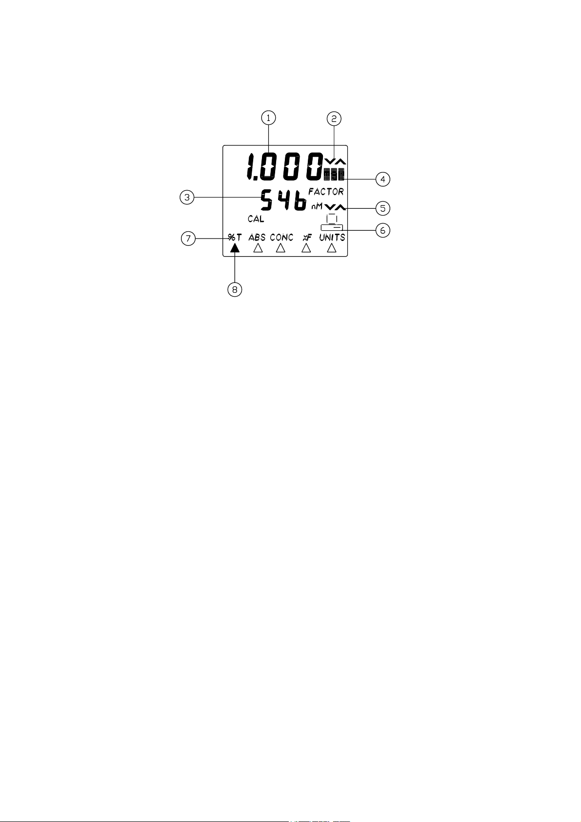
2.3 DISPLAYS
1. Primary display area - Transmission, Absorbance, Concentration
2. Primary display adjust annunciator
3. Secondary display area - Wavelength, Factor
4. Primary display units
5. Secondary display adjust annunciator
6. Operation with PC
7. Menu options - %T ABS CONC FACTOR UNITS
8. Menu pointers (for 7)
3
6300&6320D/REV F08-13
 Loading...