

Page 1

VX7020A
6.2” Double DIN Multimedia Receiver
DVD / NAV / SiriusXM-Ready®/ Built-in Bluetooth /
Pandora® / iPhone® - iPod® / USB / AV In
INSTALLATION GUIDE
What’s in the Box
The following items are supplied
with the VX7020A:
• VX7020A Head Unit
• Trim Rings
• Hardware
• Power / Speaker Output / Accessory Harness
• Remote Control
• External Microphone
• GPS Antenna
• Operation / Navigation Manual / Warranty Card
• Installation Guide
WARNING! Never install this unit where operation and viewing could interfere with
safe driving conditions.
Page 2
Optional Equipment
•
Steering Wheel Control (SWC) - The VX7020A is SWC ready for vehicles equipped with the option. See wiring diagram
for installation details. For SWC programming details, please see the operation manual.
•
Rear Camera - The VX7020A is Rear Camera ready for vehicles equipped with the option. See wiring diagram for
installation details.
Disconnect the Battery
• To prevent a short circuit, be sure to turn o the ignition and remove the negative (-) battery cable prior to installation.
NOTE: If the VX7020A is to be installed in a car equipped with an on-board drive or navigation computer, do not
disconnect the battery cable. If the cable is disconnected, the computer memory may be lost. Under these
conditions, use extra caution during installation to avoid causing a short circuit.
Replacing the Fuse
• When replacing the vehicles radio fuse always use the proper rated replacement fuse. Using a fuse with an improper rating
could damage the unit and cause a re.
ISO-DIN Installation
The VX7020A is designed to fi t into a 2.0 DIN dashboard opening. The unit has threaded holes in the chassis side panels which may
be used with the original factory mounting brackets of some Toyota, Nissan, Mitsubishi, Isuzu, Hyundai and Honda vehicles to
mount the radio to the dashboard. Please consult with your local car stereo specialty shop for assistance on this type of
installation.
1. Remove the existing factory radio from the dashboard or
center console mounting. Save all hardware and brackets as
they will be used to mount the new radio.
2. Remove the factory mounting brackets and hardware from the
existing radio and attach them to the new radio.
CAUTION! Do not exceed M5 X 6MM screw size. Longer
screws may damage components inside the chassis.
3. Place the radio in front of the dashboard opening so the wiring
can be brought through the mounting sleeve. Follow the
wiring diagram carefully and make certain all connections are
secure and insulated with wire nuts or electrical tape. After
completing the wiring connections, plug the connector into
the mating socket on the rear of the chassis. Turn the unit
on to confirm operation (vehicle ignition switch must be
“ON”). If the unit does not operate, re-check all wiring until the
problem is corrected.
4. Mount the new radio assembly to the dashboard or center
console using the reverse procedure in step 1 above.
CAUTION! Be careful not to damage the car wiring.
NOTE: It is the end-users responsibility to install and operate this unit in a manner in accordance with local, state and federal
laws. The PARKING BRAKE wire MUST BE CONNECTED as dir ected in the manual.
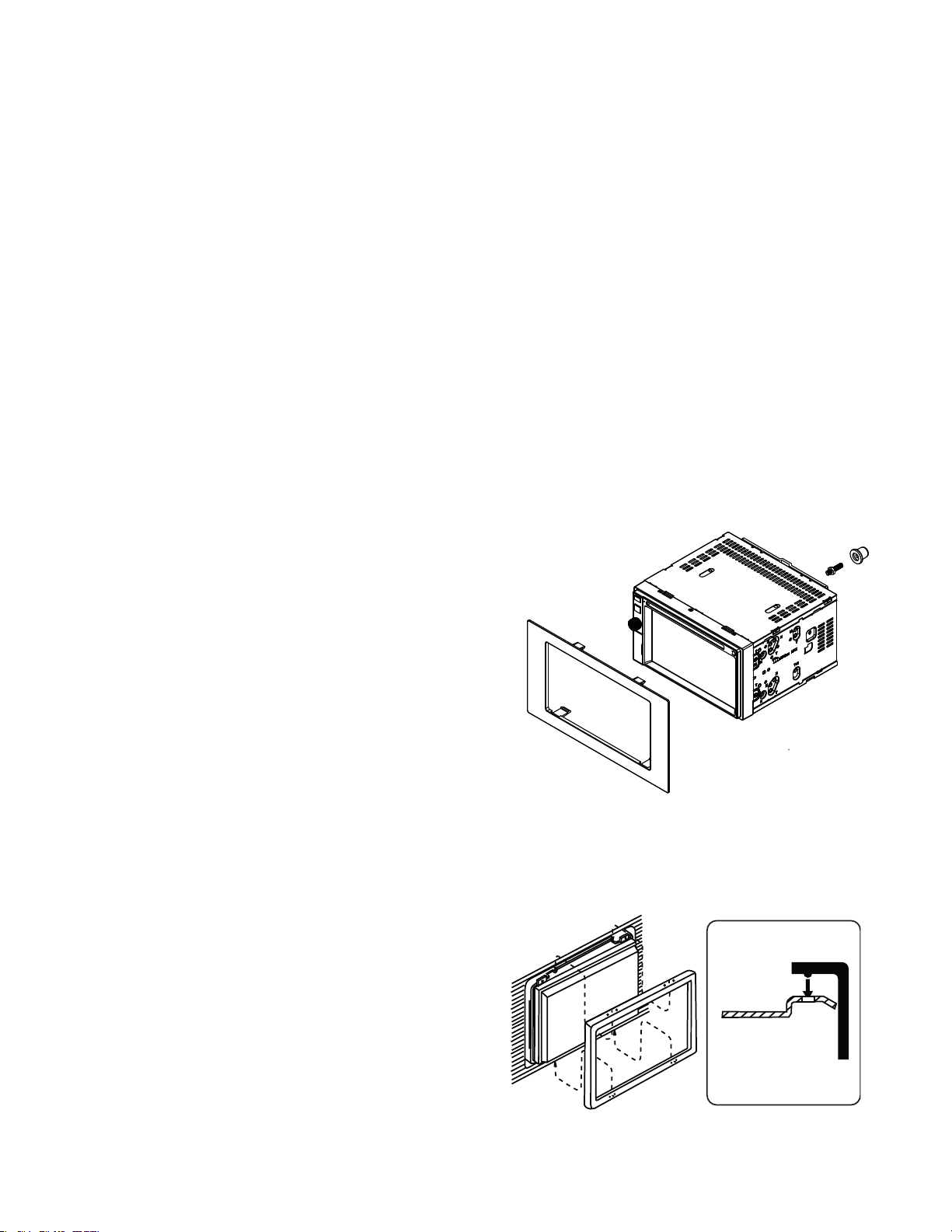
Using the Cosmetic Trim Ring
A cosmetic trim ring is supplied with the head unit for installation
exibility. This unit will t into most import dashes with little or no
modi cation to the dash board/cavity. Some US domestic vehicle
dashes will accept a Double-DIN chassis, but there is usually a
small gap between the radio and dash piece after installation is
complete. In this case, use the trim ring to conceal any gaps that
may be present.
NOTE: For proper operation of the CD/DVD player, the chassis must be mounted within 30° of horizontal. Make sure the
unit is mounted within this limitation.
2
Page 3

Wiring Diagram
CAUTION! IMPORTANT: Incorrect wiring connections can damage the unit. Follow the wiring instructions
carefully, or have the installation handled by an experienced technician
SWC A - Primary SWC Wire
SWC B - Secondary SWC Wire
SWC Ground - Chassis ground
Initial wiring of the SWC interface should include the SWC A and SWC Ground wire. If this combination of wiring does not support your vehicle functions, then
try the SWC B and SWC Ground wire combination. Do not use only SWC A and SWC B. The SWC Ground must be connected.
Some vehicles may not support all SWC functions. Professional Installation is recommended.
The VX7020A has a built-in SWC Interface compatible with most resistive type OE steering wheel controls. In most installations, only two of the three wires
will be needed to interface the OE steering wheel controls to the VX7020A.
.
Yellow RCA - Rear Camera
Black DIN Cable - SiriusXM
Black Female 3.5mm - BT Microphone
SWC (BLACK)
GREEN/WHITE
WHITE/PURPLE
WHITE/BROWN
REVERSE (+)
KEY A
KEY B
KEY GNDBROWN/BLACK
PINK
BLUE
ORANGE
TFT DIMMER (+)
POWER ANT & AMP (+)
BRAKE (-)
RED
ACC / IGNITION (+)
BLACK
GROUND (-)
YELLOW
GREEN/BLACK
GREEN
PURPLE/BLACK
RIGHT REAR SPEAKER (-)
LEFT REAR SPEAKER (+)
LEFT REAR SPEAKER (-)
BATTERY 12V (+)
GRAY/BLACK
GRAY
PURPLE
WHITE/BLACK
WHITE
RIGHT FRONT SPEAKER (-)
RIGHT REAR SPEAKER (+)
LEFT FRONT SPEAKER (-)
LEFT FRONT SPEAKER (+)
RIGHT FRONT SPEAKER (+)
SPEAKER (-)
SPEAKER (+)
Black 1mm Wire - BT Antenna
GPS Antenna
2
Page 4

www.asaelectronics.com
© 2015
Printed in China
 Loading...