

Page 1

RECEIVER BOOM BO X
JSIR900B User Guide
AUDIO OX
Released 03-07-05.
128-7369
1 of 12
Page 2

Congratulations
You are one step closer to experiencing the latest innovation in Sirius Satellite Radio. Sirius will
revolutionize your portable in-home, vehicle and family entertainment, such as camping trips and
beach excursions, using the Sirius Model JSIR900B Boom Box as the base receptacle for your
Receiver Receiver. Sirius entert ainment will enhance your listening enjoyment with:
• 130 channels of original programming, including :
65 channels of 100% commercial-free music – guaranteed;
Over 55 channels of world-class sports, news, talk and information.
Your Jensen Boom Box must be used with Receiver, Model JSIR900R (sold separately). Optional
home and vehicle kits are available at retailers where Jensen main units are sold.
Jensen Home Kit: Part Number JSIR900H
Jensen Combo Kit: Part Number JSIR900CMB
Receiver and Car Kit
© 2004 SIRIUS Satellite Radio Inc. “SIRIUS” and the SIRIUS dog logo are registered
trademarks of SIRIUS Satellite Radio Inc.
-2-
128-7369
2 of 12
Page 3

FCC Regulations
This unit complies with the interference limits relative to a Class B digital device, applicable under Part
15 of the FCC Rules regarding installation in a residential environment. If the unit is not installed in
accordance with these instructions, it could cause harmful interference to audio or television reception.
If this condition persists after corrective action, consult your dealer or experienced installation facility.
Cautions and Warnings
1. Within the home, do not install the Receiver Boom Box in a position that obstructs viewing of
any home entertainment component, such as Television, or stereo system indicators and
displays.
2. Do not install or use the JSIR900B in locations exposed to direct sunlight, or in areas subject to
extreme temperatures; do not operate the unit in moist areas, in rain, or in areas adjacent
to water such as pools, hot tubs, etc.
3. When outdoors, position the JSIR900B and antenna where there are no obvious satellite signal
obstructions such as high terrain, trees, overhangs, etc.
4. When installed indoors, unplug the AC Power Adapter from the wall outlet when the JSIR900B is
not to be used for an extended period of time. If batteries are installed, set the Power On/Off-VOL
control to the Off position to prevent unintentional battery discharge, or remove the batteries.
5. To avoid possible damage to the Receiver Boom Box caused by battery leakage, it is
recommended that the batteries be removed when the Boom Box is not being used for an
extended period of time.
6. Do not install or place the JSIR900B on an inclined or unstable surface.
7. By adhering to these warnings and safety considerations, serious accidents and/or personal
injury can be avoided.
-3-
128-7369
3 of 12
Page 4
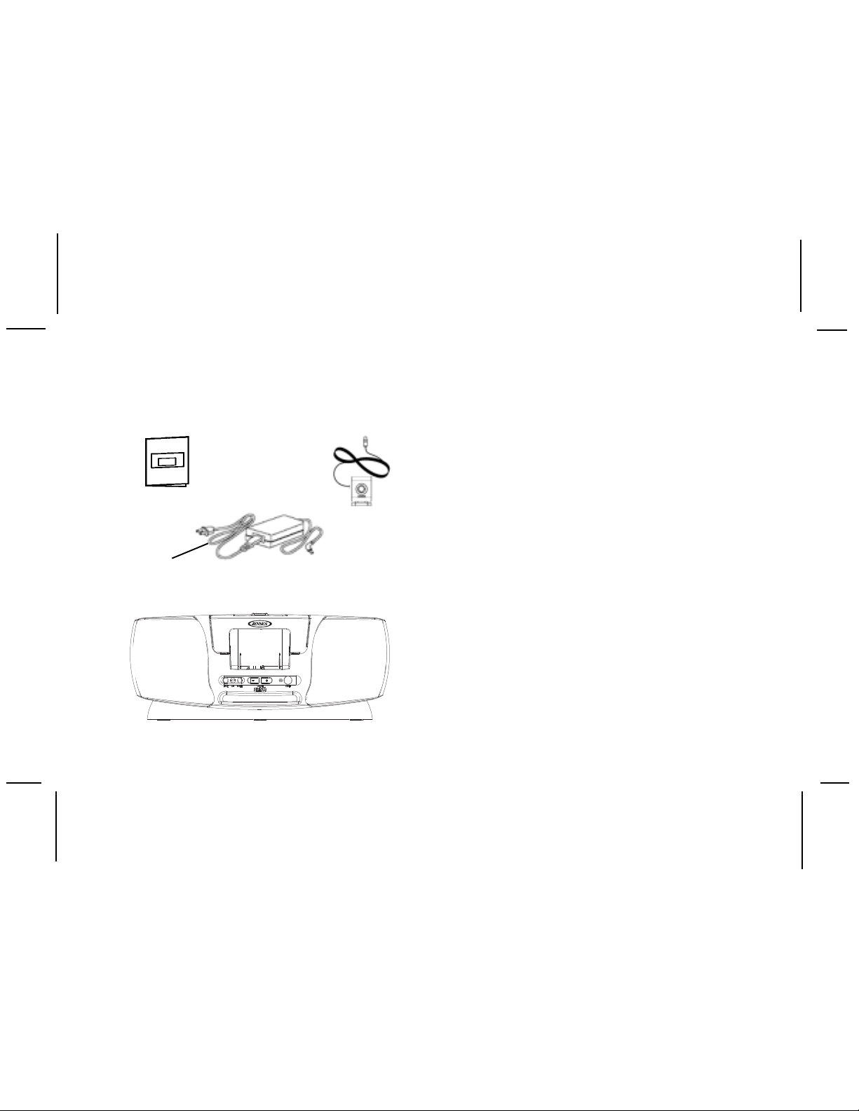
Contents JSIR900B
Users Guide
P/N 128-7369
AC/DC Power Adapter
1 pc.
(P/N 136C3585)
Antenna
(P/N 118C1129)
1 pc.
Installation/Wiring Precautions
1. If using the adapter, make sure the adapter cable
is not connected to an AC wall outlet until all interconnections have been made and verified. The
adapter power cable should be connected last.
2. Incorrect installation may cause damage to the
system.
3. For antenna positioning, refer to the Antenna
Aiming procedure outlined in the Receiver User
Guide, JSIR900R (128-7373).
AC Power Cord
(P/N 112B3376)
1 pc.
Boom Box
(P/N JSIR900B)
AUDIO OX
1 pc.
Setting Up and Installing Your Kit
NOTE: The SIRIUS® signal can be received and
processed virtually anywhere as long as there
are no obvious satellite signal obstructions
such as high terrain, trees, overhangs, etc.
However, signal reception depends mainly on
where you are, geographically, and where this
place is with respect to the orbital paths of the
Sirius satellites. In placing the antenna,
therefore, these factors must be taken into
account .
-4-
128-7369
4 of 12
Page 5
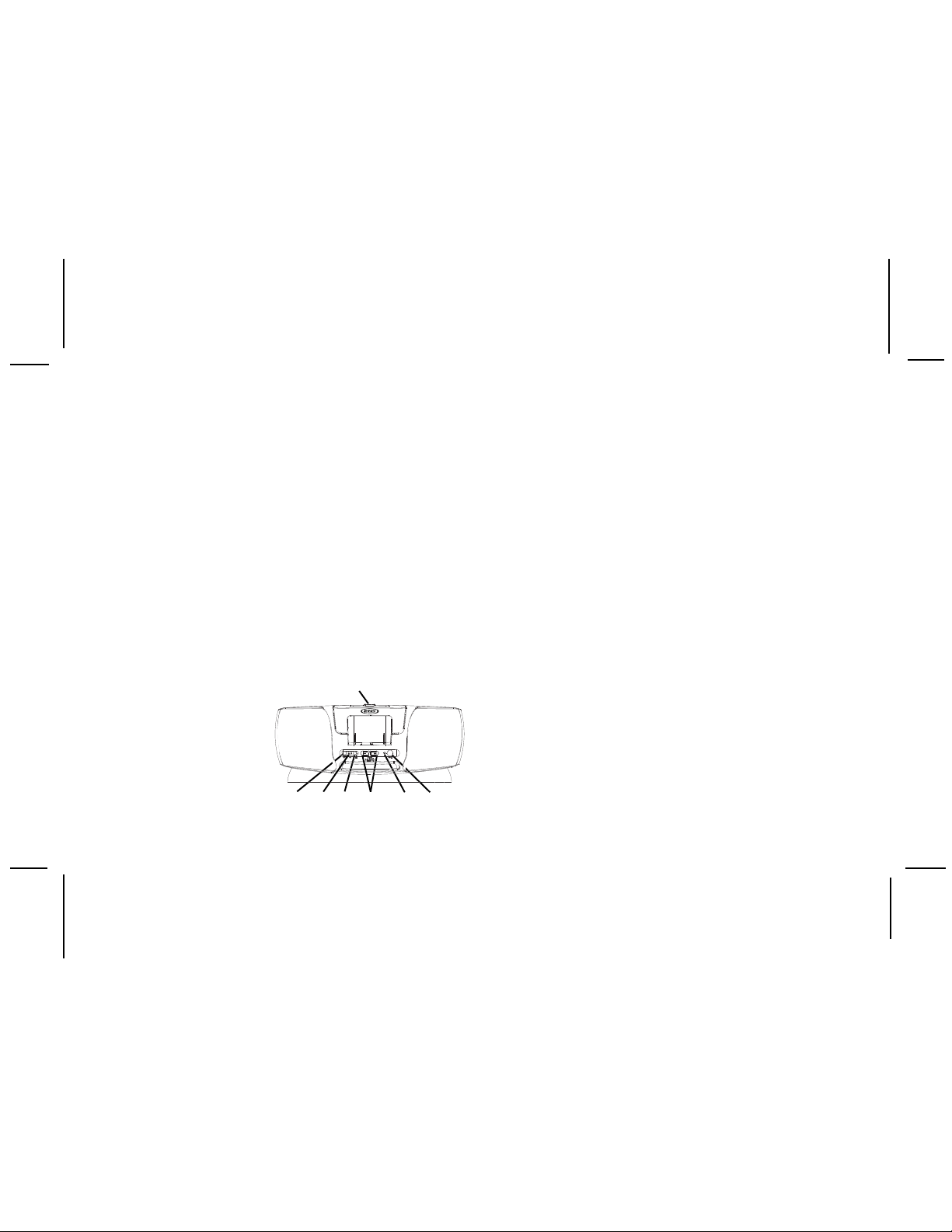
Boom Box JSIR900B Controls
The Jensen Sirius® Boom Box JSIR900B provides
Power ON/OFF and VOLUME +/- pushbuttons, and a
MODE pushbutton to toggle between Satellite Radio or
an auxiliary audio input signal. A power-on/low battery
LED is also located on the front panel.
1.
MODE Pushbutton: This pushbutton toggles
between Satellite Radio and an external audio
input signal (MP3, CD, etc.) present at the AUX
input jack.
2.
AUX Jack: Accepts an audio input signal from
an external audio device. When using the AUX
audio input, turn the Receiver off to preserve battery
power. Adjust the volume level of the external
audio device to obtain an audio output from the
JSIR900B. The volume
control on the
external audio
device should be
set to mid-range.
12
3
AUDIO OX
475
6
3.PHONES Jack: Accepts a stereo headphone jack
to provide private listening capability for the Boom
Box.
4.VOLUME +/- Pushbuttons: Increase or decrease
the volume of the audio output signal from the
JSIR900B. To increase the volume level, press the
+ pushbutton; to decrease the volume level, press
the - pushbutton.
NOTE: When the JSIR900R Receiver is installed,
the Volume buttons on the Remote Control
unit will control the audio output of the Boom
Box.
5.Power On/Low Battery LED: The LED lights
green when the Power On/Off pushbutton is
pressed to apply power to the JSIR900B. In
addition, the LED will light red to alert the user
that the batteries are nearly discharged. This
condition may cause degraded performance of
the JSIR900B.
6.Power On/Off Switch: When pressed, applies
powerto the Boom Box; the power on LED
indicator (5) lights green.
7. EJECT Button: Press this button to release the
spring-loaded cover to install and remove the
-5-
Receiver from the JSIR900B cradle.
128-7369
5 of 12
Page 6
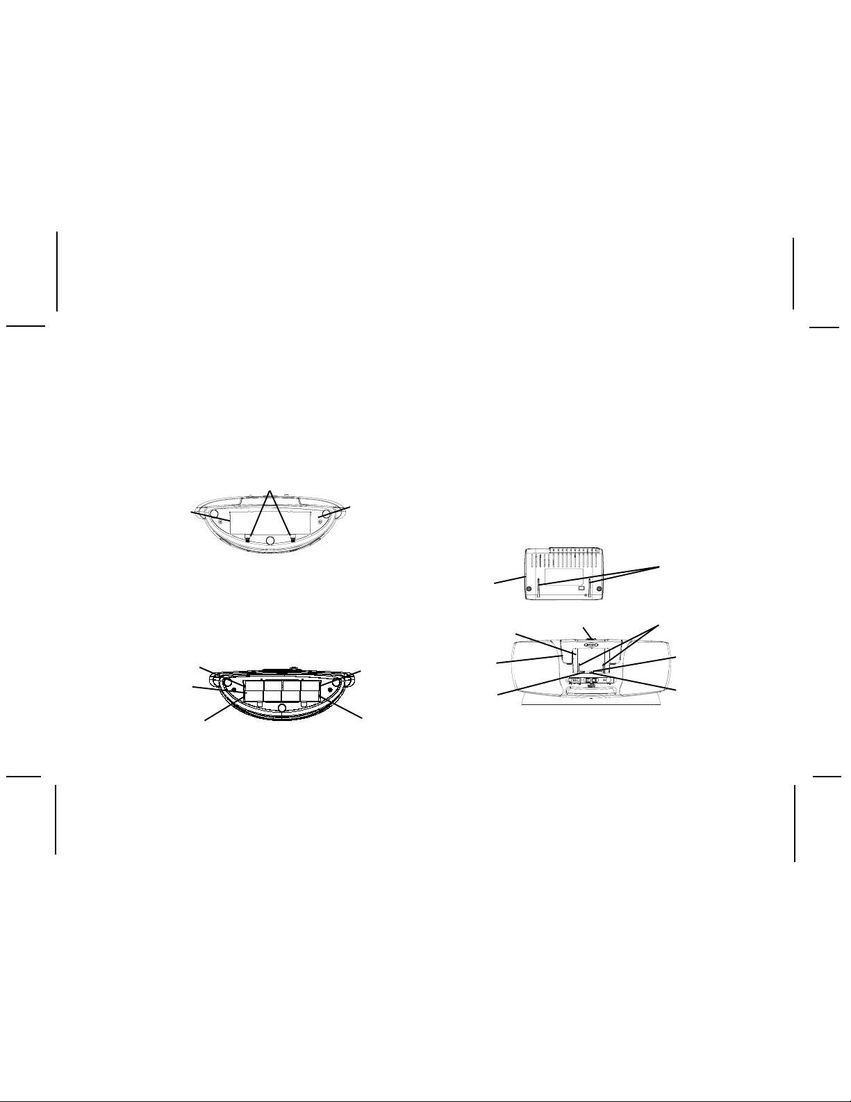
1.Battery Installation
Your Boom Box can operate independently of AC
power by installing 8 D-Cell batteries as follows:
NOTE: The batteries are bypassed automatically
whenever the supplied AC Adapter is
plugged into the DC 12V jack on the back
panel.
BATTER Y
COMPAR TMENT
COVER
1.
Turn the Boom Box upside down to access
COVER LATCHES
BOTTOM OF
BOOM BOX
the battery compartment.
2.
Push the battery cover latches forward and flip
up the battery compartment cover to the open
position.
3.
Insert eight (8) D-Cell batteries observing
battery polarity as shown; then close the cover.
BATTERY
COMPARTMENT
(COVER REMOVED)
POSITIVE
NEGATIVE
NEGATIVE
POSITIVE
2.Cabling Interconnections
You can begin to enjoy Sirius® Satellite Radio
as soon as the Receiver and Boom Box Kit
installation are complete. Set up your Jensen
JSIR900B by following the interconnect diagram.
3.Installing the Receiver in the JSIR900B
Install the Receiver as follows:
1.Press the EJECT button at the top of the JSIR900B
to open the spring-loaded cover. Carefully line up
the Receiver rear spine grooves with the Boom Box
guide spines; lower the Receiver into the Boom Box.
RECEIVER
REAR SPINE
RECEIVER
REAR VIEW
RECEIVER
COMPARTMENT
PNP COVER
SAT
CONNECTOR
EJECT BUTTON
AUDIO OX
GROOVES
JSIR900B
GUIDE
SPINES
-6-
CONNECTOR
GUIDE PIN
20-PIN
SYSTEM
CONNECTOR
128-7369
6 of 12
Page 7
2.After making sure the connectors are properly
lined up, gently press down on the Receiver to mate
the connectors together. The Receiver should now
be nestled securely in the Boom Box compartment.
Lower the JSIR900B cover into position over the
Receiver; This will prevent accidental Receiver
disconnect. Apply power to the JSIR900B by pressing
the Power ON/OFF button; the LED indicator lights
green. If the Receiver does not turn on at the same
time, press the red Power On/Off button in the upper
left corner of the Receiver front panel.
4.Removing the Receiver From the JSIR900B
Press the EJECT button on top of the Boom Box to
raise the cover. Gently grasp the Receiver from the top
an d pull straight up to disengage.
5.Installing/Positioning the Antenna
For best reception, the supplied antenna should
be placed near a window if in the house or, if
outdoors, in an open area and as high aspossible;
some repositioning may be required to achieve
optimum results. The following guidelines are
recommended:
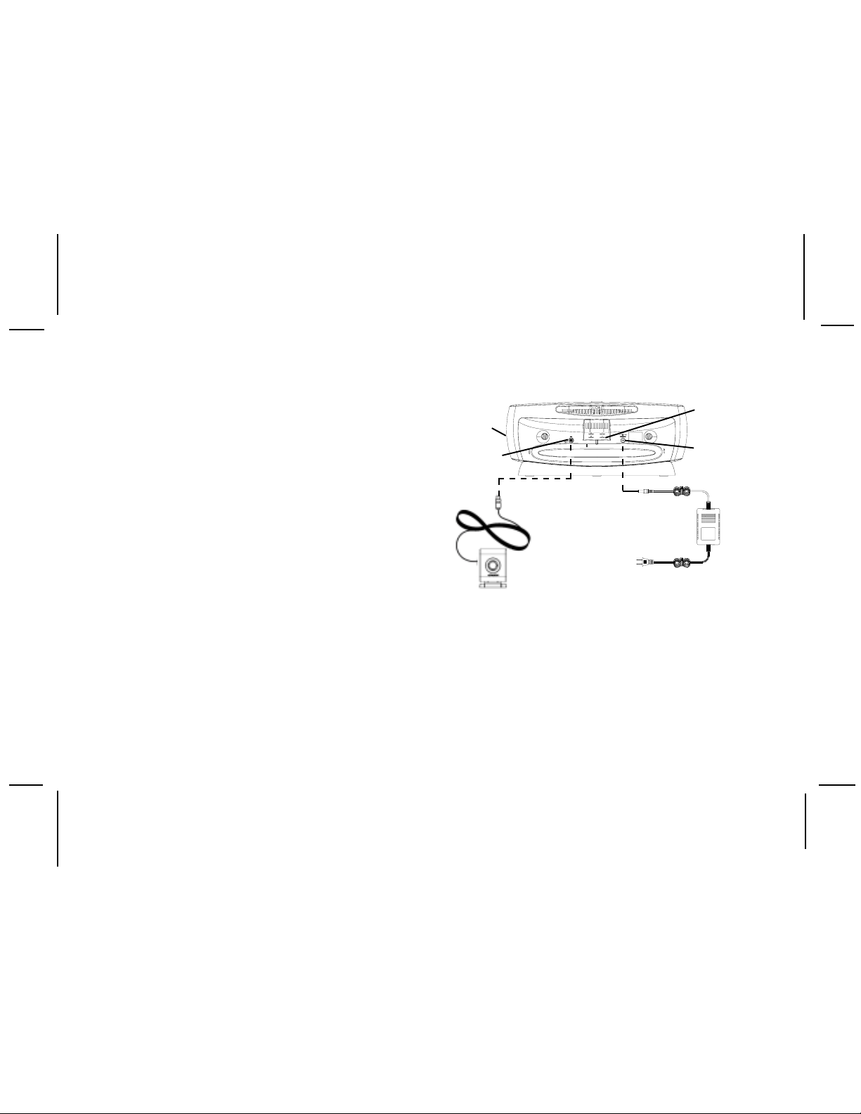
Interconnect Diagram
RECEIVER
BOOM BOX
JSIR900B
ANTENNA
JACK (ANT)
RECEIVER
ANTENNA
a. In a major city, where Sirius ground repeaters
are present, you can usually place the
antenna away from a window and still achieve
the desired results.
b. You can also place the antenna outside (on the
roof structure), provided it is clear of any
overhead obstructions. Because of the orbiting
characteristics of the Sirius Satellites, the
strength of the received signal may change over
-7-
ANTENNA
STORAGE
SHELF
DC POWER
ADAPTER
JACK
DC POWER
ADAPTER
(DC 12V 2.2A)
TO AC WALL
OUTLET
128-7369
7 of 12
Page 8

time. In most cases however, the signal should be
available continuously. If you experience a loss of
signalor audio, reposition the antenna inside the
home or outside as necessary.
6.Antenna Placement Considerations
The antenna should be placed on a relatively flat
surface whenever possible. When outdoors, the
antenna may be left in its mount atop the Boom
Box provided no overhead obstructions are present.
To mount the antenna:
a.Plug the antenna into the ANT connector on the
back of the JSIR900B.
b.Leave the antenna in place on the Boom Box,
or remove the antenna from its mount, uncoil
the antenna lead, and place it at the preferred
location inside or outside the home. If no audio
i sheard, move the antenna to different positions
on the surface until an audio output is heard. This
is the desired antenna position and, if indoors,
should be marked.
c. After determining the optimum position, turn
off JSIR900B and Receiver power . Disconnect the
poweradapter from the wall outlet receptacle
(if indoors) and disconnect the antenna cable.
d. Plan the routing of the antenna cable to the JSIR900B
ANT input when indoors. Makesure you avoid any
obstructions that could crimp, kink or twist the cable;
use protective grommets wherever rough openings
are encountered. If the antenna is mounted outside,
route the cable from the antenna position to the
interior of the home, working the cable through the
basement, under a window sill, etc.; make
adjustments and take up slack whenever necessary.
e. If outdoors, either leave the antenna in place atop the
JSIR900B, or remove the antenna and find a location
free from overhead obstructions such as tree
branches, or the roof of a tent or other temporary
shelter.
f. Plug the antenna cable into the ANT connector on
the back of the JSIR900B.
g. If not using battery power as the primary power
source, plug the female end of the DC adapter cable
into the DC 12V receptacle on the rear of the JSIR900B.
h. Plug the other end of the DC adapter cable into a
110-volt receptacle. Apply power to the Boom Box
and Receiver.
i. You are now ready to enjoy Sirius programming
outdoors or within your home.
-8-
128-7369
8 of 12
Page 9

Specifications
Nominal Output Power per Channel 5.0 Watts Rms
Total Harmonic Distortion (THD) 0.3% at 1 Watt
Frequency Response 30Hz to 20kHz
Signal-to-Noise Ratio
Speaker Impedance 8 Ohms Nominal
Headphone Output Impedance 32 Ohms
Headphone Output Level 500 mV (Maximum)
Headphone Connector Type 3.5 mm Stereo Jack
Auxiliary Input Impedance 6K-Ohms Nominal
Auxiliary Input Level 2.0 Volts (Maximum)
Auxiliary Connector Type 3.5 mm Stereo Jack
Equalizer Frequency -6dB Nominal at 2.5kHz
Overall JSIR900B Dimensions 19” W x 7.18” D x 7.8” H
Overall AC Adapter Dimensions 3.5” L x 1.3” H x 2.36” W
JSIR900B Weight 5.88 Lbs. (2670 Grams)
-9-
>65dB Maximum
485 mmW x 182 mmD x 198 mmH
90mmL x 33.5mmH x 60mmW
128-7369
9 of 12
Page 10

Maintenance
Periodic Inspection
The JSIR900B Boom Box should be inspected periodically for external damage. At least once every 30
days of use, perform the following checks:
1. Inspect the 20-pin Receiver connector for loose, bent or broken pins, misalignment, etc.; make
sure theSAT connector is intact and exhibits no apparent damage.
2. Check the VOL control for freedom of motion without binding of any kind.
3. Check that the MODE pushbutton operates correctly in that it toggles between the Satellite
Radio output and the AUX input.
4. Make sure the antenna connector at the rear of the unit is free from damage of any kind and that
the antenna lead plug mates correctly and securely.
5. Make sure the DC 12V connector at the rear of the unit is also free from damage of any kind and
that the AC Adapter plug mates correctly and securely.
6. Check the antenna for any physical damage; make sure the antenna lead is secure and not
nicked or frayed.
7. Inspect the overall Boom Box case and speaker grilles for damage such as nicks, scratches
punctures, etc.
Cleaning the JSIR900B Boom Box
When cleaning the Boom Box, make sure the AC Adapter is unplugged from the power source. Do not
use liquid cleaners or aerosol cleaners. Use a lint-free cloth lightly dampened with water for cleaning
the exterior of the Boom Box only .
-10-
128-7369
10 of 12
Page 11
Troubleshooting
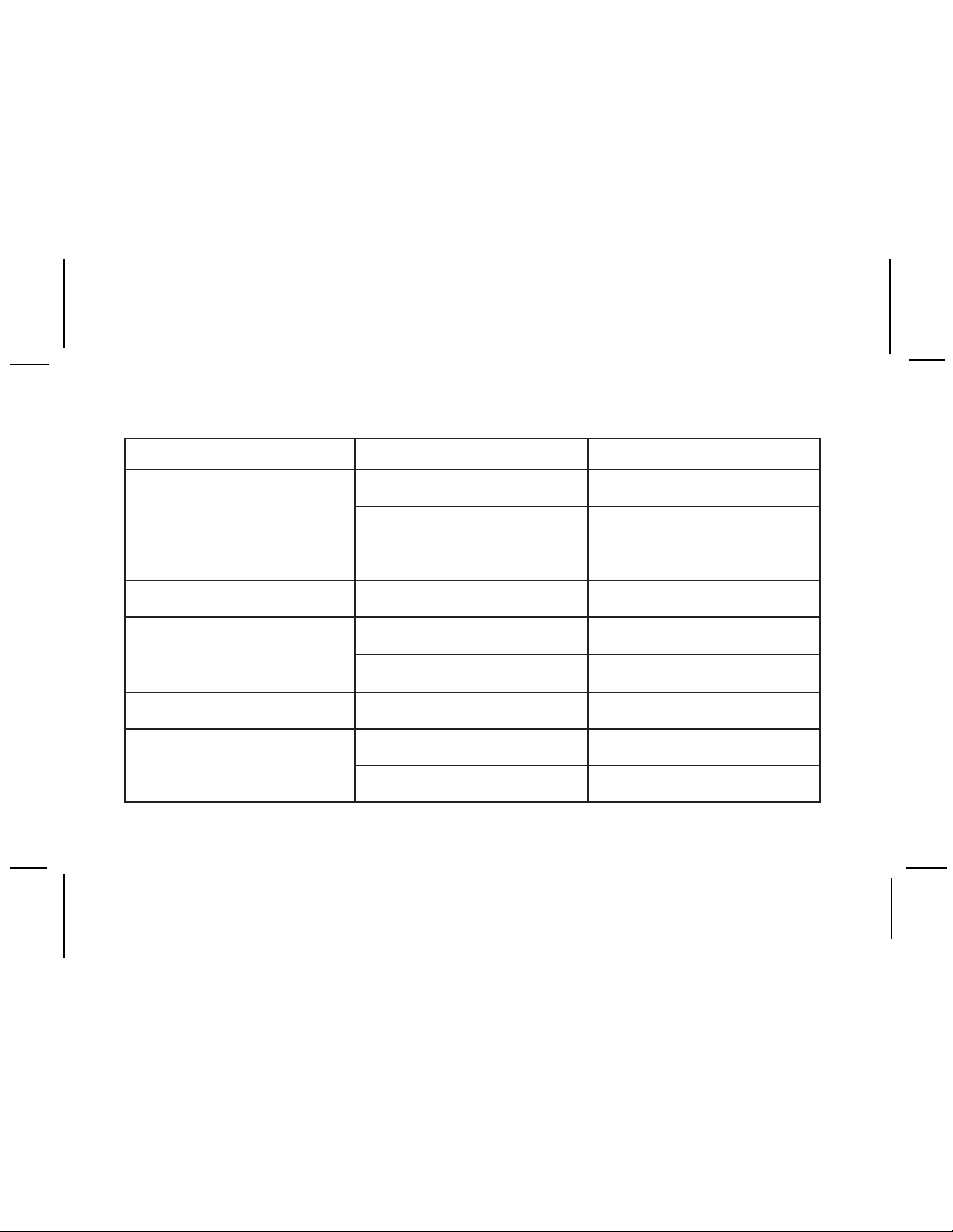
TLUAF
nonruttonseodmetsySffoottessirewoprevieceR revieceRehtgnisunorewoprevieceRnruT
ELBABORP
ESUAC
cnidellatsnirodellatsnitonseirettaB ytiraloptcerrocgnivresboseirettabllatsnI
yltcerro
YDEMER
nottubffo/norewoP
SJ
seirettab
noitarepotnettimretnIlevelyrettabwoLseirettabecalpeR
ORREANNETNA otdetcennoctonannetnaetilletaS
gnisuetarepotonseodB009-RI
delbasidsinoitarepoyrettab
egassemR
egassemLANGISGNIRIUQCA annetnadnuorarorevoselcatsborofkcehC ybraenetanimileotnoitacolegnahC
srekaepsB009RISJmorfdnuosoNdellatsnisenohpdaeHsenohpdaehevomeR
lenapraerB009RISJ
(edomtnerrocnI oiduaderisedrofnottubhsupEDOMsserP
sirotcennocrewopCAehtsagnolsA
B009RISJehtfolenapraerehtotdehcatta
ldarcnidetaesylmriftonrevieceR erusneotelttuhSehtnonwodylmrifsserP
e
noitceles)ecruos
B009RISJ
lenap
tcennocxoBmooB
ro
).cte,segdirb(selcatsbo
folenapraermorfrotcennocrewopevomeR
raerB009RISJotannetnaetilletastcennoC
ehtotdetamylmrifsirotcennocehttaht
)tupniXUArooidaRetilletaS(langis
-11-
128-7369
11 of 12
Page 12
12 MONTH LIMITED WARRANTY
AUDIOVOX CORPORATION (the Company) warrants to the original retail purchaser of this product that should this product or any part thereof,
under normal use and conditions, be proven defective in material or workmanship within 12 months from the date of original purchase, such defect(s)
will be repaired or replaced with new or reconditioned product (at the Company's option) without charge for parts and repair labor.
To obtain repair or replacement within the terms of this Warranty, the product is to be delivered with proof of warranty coverage (e.g. dated bill
of sale), specification of defect(s), transportation prepaid, to an approved warranty station or the Company at the address shown below.
This Warranty does not extend to the elimination of externally generated static or noise, to costs incurred for installation, removal or reinstallation
of the product, damage to speakers, accessories, or vehicle and home electrical systems, malfunction of satellite transmissions, repeater signal
or receiver unit.
This Warranty does not apply to any product or part thereof which, in the opinion of the Company, has suffered or been damaged through alteration,
improper installation, mishandling, misuse, neglect, accident, or by removal or defacement of the factory serial number/bar code label(s). THE
EXTENT OF THE COMPANY'S LIABILITY UNDER THIS WARRANTY IS LIMITED TO THE REPAIR OR REPLACEMENT PROVIDED ABOVE
AND, IN NO EVENT, SHALL THE COMPANY'S LIABILITY EXCEED THE PURCHASE PRICE PAID BY PURCHASER FOR THE PRODUCT.
This Warranty is in lieu of all other express warranties or liabilities. ANY IMPLIED WARRANTIES, INCLUDING ANY IMPLIED WARRANTY OF
MERCHANTABILITY, SHALL BE LIMITED TO THE DURATION OF THIS WRITTEN WARRANTY. ANY ACTION FOR BREACH OF ANY
WARRANTY HEREUNDER INCLUDING ANY IMPLIED WARRANTY OF MERCHANTABILITY MUST BE BROUGHT WITHIN A PERIOD OF
48 MONTHS FROM DATE OF ORIGINAL PURCHASE. IN NO CASE SHALL THE COMPANY BE LIABLE FOR ANY CONSEQUENTIAL OR
INCIDENTAL DAMAGES FOR BREACH OF THIS OR ANY OTHER WARRANTY, EXPRESS OR IMPLIED, WHATSOEVER. No person or
representative is authorized to assume for the Company any liability other than expressed herein in connection with the sale of this product.
Some states do not allow limitations on how long an implied warranty lasts or the exclusion or limitation of incidental or consequential damage
so the above limitations or exclusions may not apply to you. This Warranty gives you specific legal rights and you may also have other rights
which vary from state to state.
U.S.A. : AUDIOVOX CORPORATION, 150 MARCUS BLVD., HAUPPAUGE, NEW YORK 11788 ! 1-800-645-4994
CANADA : CALL 1-800-645-4994 FOR LOCATION OF WARRANTY STATION SERVING YOUR AREA
For Customer Service
Visit our Website at
www.jensen.com
© 2005 Audiovox Electronics Corporation
Product Information, Photos,
FAQs, Owner’s Manuals
128-7369
128-7369
12 of 12
 Loading...