

Janome 13512, 14412, 15312, 234 Service Manual

SERVICE MANUAL
MODEL: 13512, 14412, 15312

CONTENTS
TROUBLESHOOTING .................................................................................................. 1 - 3
SERVICE ACCESS (1) FACE COVER, BELT COVER ..................................................... 4
SERVICE ACCESS (2) BASE PLATE .............................................................................. 5
SERVICE ACCESS (3) FRONT COVER .......................................................................... 6
SERVICE ACCESS (4) REAR COVER ............................................................................ 7
TOP TENSION .................................................................................................................. 8
BOBBIN TENSION ............................................................................................................ 9
PRESSER BAR HEIGHT AND ALIGNMENT .................................................................. 10
NEEDLE SWING ............................................................................................................. 11
NEEDLE DROP ............................................................................................................... 12
CLEARANCE BETWEEN NEEDLE AND HOOK (ADJUSTMENT METHOD NO.1) ....... 13
CLEARANCE BETWEEN NEEDLE AND HOOK (ADJUSTMENT METHOD NO.2) ....... 14
FEED DOG HEIGHT ....................................................................................................... 15
NEEDLE BAR HEIGHT ................................................................................................... 16
NEEDLE TIMING TO SHUTTLE ...................................................................................... 17
BUTTONHOLE FEED BALANCE .................................................................................... 18
FEED BALANCE ON STRETCH STITCH ....................................................................... 19
BARTACK FEED OF BUTTONHOLE .............................................................................. 20
DISENGAGEMENT OF CAM FOLLOWER ..................................................................... 21
MOTOR BELT TENSION ................................................................................................. 22
WIRING ........................................................................................................................... 23
PARTS LIST ............................................................................................................. 24 - 41

1
TROUBLESHOOTING
PROBLEM CAUSE REMEDY REFERENCE
1. Skipping 1. Needle is not inserted Insert the needle properly.
stitches properly.
2. Needle is bent or worn. Change the needle.
3. Incorrectly threaded Rethread.
4. Needle or thread are Use the recommended sewing
inappropriate for fabric being needle and thread.
sewn.
5. Sewing on stretch fabric Use A #11 blue tip needle.
6. Inappropriate needle bar See mechanical adjustment P. 16
height
“
Needle bar height.”
7. Inappropriate needle to hook See mechanical adjustment P. 17
timing “Needle timing to shuttle.”
8. Inappropriate needle to hook See mechanical adjustment P. 13, 14
clearance “Clearance between needle and
hook.”
2. Fabric not 1. Incorrect feed dog height See mechanical adjustment P. 15
moving “Feed dog height.”
2. Thread on bottom side of Make sure to bring both needle
fabric is jammed up. and bobbin thread under the foot
when starting sewing.
3. Feed dog teeth are worn. Change the feed dog.

2
PROBLEM CAUSE REMEDY REFERENCE
3. Breaking 1. Initial sewing speed is too fast. Start with medium speed.
upper thread
2. Thread path is incorrect. Use the proper thread path.
3. Needle is bent or dull. Replace with a new needle.
4. Upper thread tension is Adjust upper thread tension P. 8
too strong. correctly.
5. Needle size is inappropriate Use appropriate needle and
for fabric. thread for fabric in use.
6. Needle eye is worn. Change the needle.
7. Needle hole in needle plate is Repair the hole or replace the
worn or burred. needle plate.
4. Breaking 1. Incorrectly thread bobbin case. Thread bobbin case correctly.
bobbin thread
2. Too much thread is around on Adjust the position of stopper.
the bobbin.
3. Lint is stuck inside the hook Clean the hook race.
race.
4. Thread quality is too low. Change to a high quality sewing
thread.
5. Thread is jamming around the Clear out the jamming thread.
bobbin.
6. Bobbin thread tension is too Adjust bobbin thread tension P. 9
strong. correctly.
5. Needle 1. Needle is hitting the needle See mechanical adjustment P. 12
breaks plate. “Needle drop .”
2. Needle is bent or worn. Change the needle.
3. Needle is hitting the hook race. See mechanical adjustment P. 13, 14
“Clearance between needle and
hook .”
4. The fabric moves while the See mechanical adjustment P. 11
needle is piercing it, or the “Needle swing.”
needle zigzags while in fabric.
5. Fabric is being pulled too Guide the fabric gently while
strongly while sewing. sewing.

3
PROBLEM CAUSE REMEDY REFERENCE
6. Noisy 1. Backlash between shuttle hook See mechanical adjustment P. 14
operation gear and lower shaft gear is “Clearance between needle and
too great. hook (NO. 2).”
2. Lower shaft gear is loose. Eliminate the looseness.
3. Inappropriate belt tension. See mechanical adjustment P. 22
“Motor belt tension.”
4. Upper shaft gear is loose. Eliminate the looseness.
5. Not enough oil. Oil all moving parts.
7. Deformation of 1. Inappropriate zigzag See mechanical adjustment P. 11
pattern synchronization. “Needle swing.”
2. Inappropriate disengagement See mechanical adjustment P. 21
of cam follower. “disengagement of cam follower.”
3. Upper thread tension is too Adjust upper thread tension P. 8
strong. correctly.
4. Inappropriate feed balance See mechanical adjustment P. 19
BALANCE "Feed balance on stretch stitch."
4
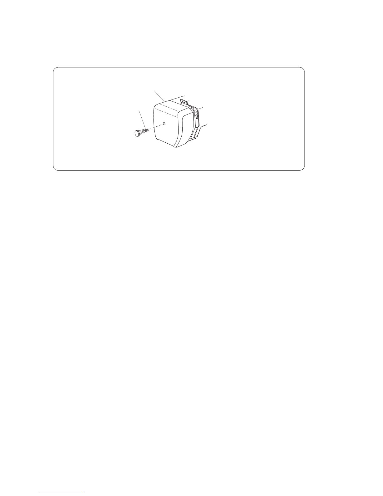
(A)
Face cover
SERVICE ACCESS (1)
FACE COVER
TO REMOVE
1. Remove the face cover by removing the setscrew (A).
TO ATTACH
2. Mount the face cover in reverse procedure of the removing.
5
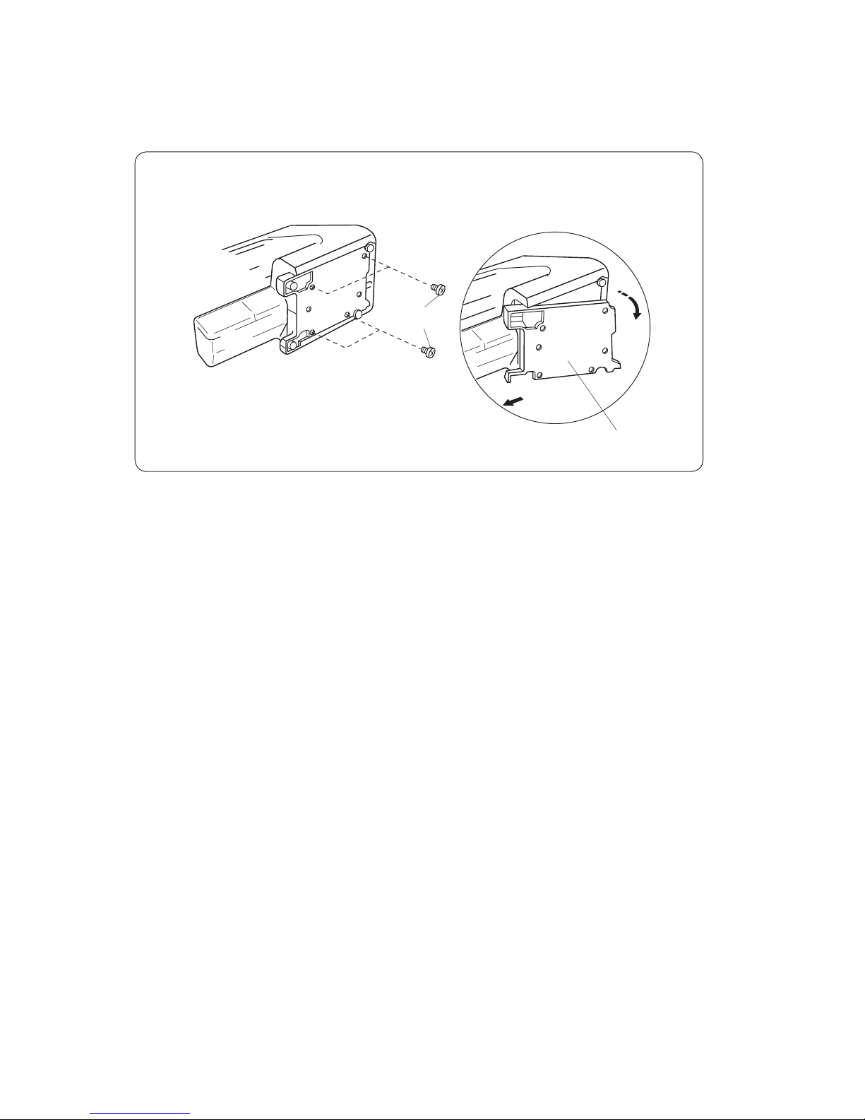
Base plate
(A)
SERVICE ACCESS (2)
BASE PLATE
TO REMOVE
1. Remove the setscrews (A).
2. Remove the base plate.
TO ATTACH
3. Mount the base plate in reverse procedure of the removing.
6
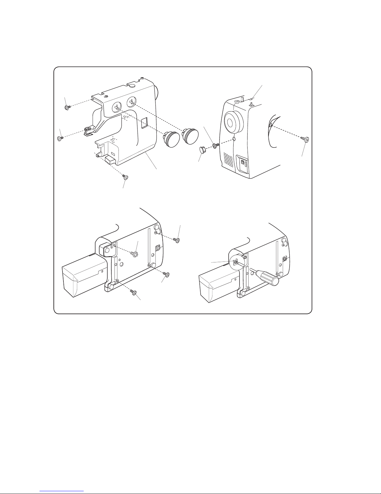
SERVICE ACCESS
FRONT COVER
TO REMOVE:
1. Loosen the set screws (A), (B), and (C), and then, remove the front cover by removing the set screws
(D), (E), (F), (G), (H), (I) and (J).
NOTE:
Unhook the tab (L) from the rear cover when remove the front cover.
TO ATTACH:
2. Follow the above procedure in reverse.
(D)
(A)
(E)
(G)
(B)
(F)
(H)
(L)
(C)
(I)
(J)
Cap
Front cover
 Loading...