

Page 1

X-TYPE 2003.5MYNAS Driver’s Handbook
Page 2

Jaguar X-TYPE
Driver’s Handbook
Foreword
JAGUAR CARS LIMITED, as manufacturer, is
dedicated to the design and production of vehicles which meet
the expectations of the world’s most discerning purchasers.
This handbook forms part of the owner literature supplied with
your vehicle. It is designed to complement the relevant features
and systems of the vehicle, and make them easy to understand
and operate.
The information contained in this handbook applies to a range
of vehicles and not to a specific vehicle. For the specification of
a particular vehicle, owners should consult their Jaguar Retailer.
The manufacturer reserves the right to vary its specifications
with or without notice, and at such times and in such manner as
it thinks fit. Major as well as minor changes may be involved in
accordance with the Manufacturer’s policy of constant product
improvement.
Published January 2003 by Technical Service and Communications Jaguar Cars Limited Publication Part No. JJM 18 02 20/35
To cover changes, it is sometimes necessary to issue one or
more handbook supplements. When reading this handbook,
check the owner literature for possible supplements.
For full details of the owner literature originally supplied with
the vehicle, owners should consult their Jaguar Retailer.
All rights reserved. No part of this publication may be
reproduced, stored in a retrieval system or transmitted, in any
form, electronic, mechanical, photocopying, recording or other
means without prior written permission from the
Service Division of Jaguar Cars Limited.
Page 3

Contents
1. Owner information
General information . . . . . . . . . . . . . . . . . . . . . . . . . . . 1 - 1
Warnings, Cautions and Notes . . . . . . . . . . . . . . . . . . . 1 - 2
Health and safety . . . . . . . . . . . . . . . . . . . . . . . . . . . . . 1- 3
Regular servicing. . . . . . . . . . . . . . . . . . . . . . . . . . . . . . 1-4
Jaguar diagnostic system . . . . . . . . . . . . . . . . . . . . . 1 - 4
Vehicle identification . . . . . . . . . . . . . . . . . . . . . . . . . . 1 - 5
Protect the environment. . . . . . . . . . . . . . . . . . . . . . . . 1 - 6
Mobile/portable telephones . . . . . . . . . . . . . . . . . . . . . 1 - 6
Window tinting. . . . . . . . . . . . . . . . . . . . . . . . . . . . . . . 1-6
Touch-screen display . . . . . . . . . . . . . . . . . . . . . . . . . . 1-7
2. Security and locks
Ignition switch . . . . . . . . . . . . . . . . . . . . . . . . . . . . . . . 2-1
Vehicle security . . . . . . . . . . . . . . . . . . . . . . . . . . . . . . 2-2
Key transmitter . . . . . . . . . . . . . . . . . . . . . . . . . . . . 2-3
Door locks and handles . . . . . . . . . . . . . . . . . . . . . . . . 2-5
Vehicle locking and unlocking . . . . . . . . . . . . . . . . . 2-5
Child safety locks . . . . . . . . . . . . . . . . . . . . . . . . . . 2 - 7
Alarms and audible signals . . . . . . . . . . . . . . . . . . . . . 2-10
Security features . . . . . . . . . . . . . . . . . . . . . . . . . . . . . 2-11
Radio frequency . . . . . . . . . . . . . . . . . . . . . . . . . . 2 - 11
HomeLink
®
Universal Transceiver . . . . . . . . . . . . . . . . 2 - 12
3. Before driving
Occupant protection. . . . . . . . . . . . . . . . . . . . . . . . . . . 3 -1
Seat belts . . . . . . . . . . . . . . . . . . . . . . . . . . . . . . . . 3 -1
Advanced occupant restraint system . . . . . . . . . . . . 3-4
Child safety . . . . . . . . . . . . . . . . . . . . . . . . . . . . . . 3-11
Seat adjustment . . . . . . . . . . . . . . . . . . . . . . . . . . . . . 3-19
Steering column adjustment . . . . . . . . . . . . . . . . . . . . 3- 21
Clock . . . . . . . . . . . . . . . . . . . . . . . . . . . . . . . . . . . . . 3-21
Door window operation . . . . . . . . . . . . . . . . . . . . . . . 3-22
Window anti-trap feature . . . . . . . . . . . . . . . . . . . 3-23
Mirrors . . . . . . . . . . . . . . . . . . . . . . . . . . . . . . . . . . . . 3-24
Door rear view mirrors . . . . . . . . . . . . . . . . . . . . . 3-24
Interior rear view mirror . . . . . . . . . . . . . . . . . . . . 3-25
Luggage compartment. . . . . . . . . . . . . . . . . . . . . . . . . 3-26
4. On the road
Instruments . . . . . . . . . . . . . . . . . . . . . . . . . . . . . . . . . 4-1
Warning lights . . . . . . . . . . . . . . . . . . . . . . . . . . . . . . . 4-2
Audible warnings . . . . . . . . . . . . . . . . . . . . . . . . . . . . . 4-8
Message centre . . . . . . . . . . . . . . . . . . . . . . . . . . . . . . . 4-9
Messages . . . . . . . . . . . . . . . . . . . . . . . . . . . . . . . . 4-10
Trip computer. . . . . . . . . . . . . . . . . . . . . . . . . . . . . . . 4-13
Cruise (speed) control . . . . . . . . . . . . . . . . . . . . . . . . . 4-16
Page 4

Contents
4. On the road (continued)
Exterior lighting . . . . . . . . . . . . . . . . . . . . . . . . . . . . . . 4-18
Interior lighting . . . . . . . . . . . . . . . . . . . . . . . . . . . . . . 4-21
Reverse park control . . . . . . . . . . . . . . . . . . . . . . . . . . 4-23
Sunroof . . . . . . . . . . . . . . . . . . . . . . . . . . . . . . . . . . . . 4-24
Wipers and washers . . . . . . . . . . . . . . . . . . . . . . . . . . . 4 - 25
Parkbrake. . . . . . . . . . . . . . . . . . . . . . . . . . . . . . . . . . . 4- 27
Horn . . . . . . . . . . . . . . . . . . . . . . . . . . . . . . . . . . . . . . 4 - 27
Interior features . . . . . . . . . . . . . . . . . . . . . . . . . . . . . . 4-28
Sun visors and vanity mirrors . . . . . . . . . . . . . . . . . 4- 30
Cigar lighter and ashtray. . . . . . . . . . . . . . . . . . . . . 4-30
Rear centre armrest . . . . . . . . . . . . . . . . . . . . . . . . 4-30
Glove compartment . . . . . . . . . . . . . . . . . . . . . . . . 4-31
Rear sun blind . . . . . . . . . . . . . . . . . . . . . . . . . . . . 4-32
Starting/stopping the vehicle . . . . . . . . . . . . . . . . . . . . 4- 33
Automatic transmission . . . . . . . . . . . . . . . . . . . . . . . . 4 - 35
Gear-shift interlock. . . . . . . . . . . . . . . . . . . . . . . . . 4 - 35
Gear selector positions . . . . . . . . . . . . . . . . . . . . . . 4 - 35
Sport mode. . . . . . . . . . . . . . . . . . . . . . . . . . . . . . . 4-37
Manual transmission . . . . . . . . . . . . . . . . . . . . . . . . . . 4 - 37
Anti-lock braking system (ABS) . . . . . . . . . . . . . . . . . . . 4 - 38
Dynamic stability control (DSC) . . . . . . . . . . . . . . . . . . 4 - 40
General driving information . . . . . . . . . . . . . . . . . . . . . 4-41
Winter driving . . . . . . . . . . . . . . . . . . . . . . . . . . . . 4-42
Touring. . . . . . . . . . . . . . . . . . . . . . . . . . . . . . . . . . 4 - 43
Towing a caravan or trailer. . . . . . . . . . . . . . . . . . . 4-44
Fuel and refuelling . . . . . . . . . . . . . . . . . . . . . . . . . . . . 4-45
5. Climate control
Introduction. . . . . . . . . . . . . . . . . . . . . . . . . . . . . . . . . . 5-1
Automatic climate control with LCD screen . . . . . . . . . . 5 - 4
Automatic climate control with touch-screen . . . . . . . . . 5-8
6. Roadside emergency
Inertia switch . . . . . . . . . . . . . . . . . . . . . . . . . . . . . . . . . 6-1
Emergency starting . . . . . . . . . . . . . . . . . . . . . . . . . . . . . 6-2
Wheel changing and jacking. . . . . . . . . . . . . . . . . . . . . . 6-4
Vehicle recovery . . . . . . . . . . . . . . . . . . . . . . . . . . . . . . 6-8
Bulb renewal . . . . . . . . . . . . . . . . . . . . . . . . . . . . . . . . 6-11
Fuses and fuse boxes . . . . . . . . . . . . . . . . . . . . . . . . . . 6 - 15
Fuse box locations . . . . . . . . . . . . . . . . . . . . . . . . . 6-16
7. Maintenance
General maintenance . . . . . . . . . . . . . . . . . . . . . . . . . . . 7-1
Hood release . . . . . . . . . . . . . . . . . . . . . . . . . . . . . . . . . 7 - 3
Regular checks . . . . . . . . . . . . . . . . . . . . . . . . . . . . . . . . 7-4
Checking and topping up . . . . . . . . . . . . . . . . . . . . . . . . 7 - 6
Battery . . . . . . . . . . . . . . . . . . . . . . . . . . . . . . . . . . . . . 7 -14
Windscreen wipers . . . . . . . . . . . . . . . . . . . . . . . . . . . 7-17
Tyres . . . . . . . . . . . . . . . . . . . . . . . . . . . . . . . . . . . . . . 7-18
Tyre pressures . . . . . . . . . . . . . . . . . . . . . . . . . . . . 7-18
Vehicle care . . . . . . . . . . . . . . . . . . . . . . . . . . . . . . . . . 7-22
Interior care . . . . . . . . . . . . . . . . . . . . . . . . . . . . . . 7 - 22
Exterior care. . . . . . . . . . . . . . . . . . . . . . . . . . . . . . 7-23
Electrical accessories . . . . . . . . . . . . . . . . . . . . . . . . . . 7-25
Page 5

Contents
8. Specifications
Vehicle data . . . . . . . . . . . . . . . . . . . . . . . . . . . . . . . . . 8-1
Weights (average/approximate) . . . . . . . . . . . . . . . . 8- 2
Roof-rack capacity and trailer weights . . . . . . . . . . . 8- 3
Dimensions . . . . . . . . . . . . . . . . . . . . . . . . . . . . . . . 8 - 4
Wheels and tyres. . . . . . . . . . . . . . . . . . . . . . . . . . . 8 - 5
‘R’ performance wheels . . . . . . . . . . . . . . . . . . . . . . 8-5
Tyre pressures . . . . . . . . . . . . . . . . . . . . . . . . . . . . . 8 - 6
Tow-bar fixing points . . . . . . . . . . . . . . . . . . . . . . . 8-7
A comprehensive index is located at the back of this Handbook.
Page 6

1 Owner information
Owner information 1-1
General information
Whether you are new to the Jaguar
marque or have previously owned Jaguar
vehicles, we are pleased that you have
made Jaguar your choice of vehicle this
time.
For safety and the pleasure you will get
from your new vehicle, please take the
time to get well acquainted with your
vehicle by reading the Handbooks.
Details of the vehicle warranty are
contained within the ‘Passport to Service’
booklet for USA and Canada or,
for Mexico, the ‘Service Record and
Warranty’ book.
When left-hand or right-hand is used in
the text, this refers to the left-hand side
or right-hand side of the vehicle, viewed
from the rear.
This Handbook describes every option
and model variant available and
therefore some of the items covered
may not apply to your particular
vehicle.
Jaguar Retailers
Jaguar Retailers are chosen with care.
Each is dedicated to providing a Sales,
Service and Spare Parts facility of the
highest standard.
Jaguar Retailers are provided with full
technical support from the factory, with
comprehensive training for all their
technicians. Retailers’ workshops operate
to a high standard and have all the
necessary tools and equipment essential
to maintain or repair Jaguar vehicles.
A current list of Retailers is included in
the vehicle literature pack.
Genuine Jaguar parts and
accessories
Your Jaguar Retailer can supply you with
genuine replacement parts and
accessories which are fully approved to
Jaguar’s original equipment specification.
This will ensure that the safety and
performance of your vehicle is
maintained for your complete peace of
mind.
Please note that fitment of non-genuine
parts may invalidate the vehicle warranty
if a subsequent fault occurs due to fitting
sub-standard replacement parts or
accessories.
Jaguar parts distribution service
Jaguar Retailers stock a large number of
parts to keep your vehicle maintained
and back on the road as quickly as
possible. Their service is supported by
strategically positioned Jaguar parts
distribution centres throughout North
America, providing next day delivery to
the majority of Retailers.
Accessories
A full range of Jaguar Engineering
approved accessories including safety,
stowage, touring, leisure and lifestyle
products are just some of those available
from your Jaguar Retailership.
Please ask your Jaguar Retailer for an
up-to-date brochure so you can select
your requirements from the latest range.
Page 7
1-2 Owner information
Warnings, Cautions and
Notes
Take particular note of WARNINGS,
Cautions and Notes given throughout this
Handbook.
!
WARNING:
A w arni ng is a procedure which must
be followed precisely to help avoid
the risk of personal injury.
Caution: A caution is a procedure
which must be followed precisely to
reduce the possibility of damage to
the vehicle and resultant risk of
personal injury or inconvenience.
Note: A note is a procedure which will
help avoid difficulties in the operation of
the vehicle.
Vehicle Handbooks
!
WARNING:
Remember to pass on the Vehicle
Handbooks when reselling the
vehicle. Handbooks are integral parts
of the vehicle.
Warning symbols on the
vehicle
On encountering the warning triangle or
open book symbol on the vehicle, it is
important that before touching this part
of the vehicle or attempting adjustments
of any kind you consult the relevant
section of this Handbook.
Caution: Do not remove any warning
labels from the underhood area or
inside the vehicle.
Reporting Safety Defects
(USA only)
If you believe that your vehicle has a
defect which could cause a crash or could
cause injury or death, you should
immediately inform the National
Highway Traffic Safety Administration
(NHTSA) in addition to notifying
Jaguar Cars.
If NHTSA receives similar complaints,
it may open an investigation, and if it
finds that a safety defect exists in a group
of vehicles, it may order a recall and
remedy campaign.
However, NHTSA cannot become
involved in individual problems between
you, your Retailer, or Jaguar Cars.
To contact NHTSA, you may either call
the Auto Safety Hotline toll-free at
1–800–424–9393 (or 366–0123 in
Washington D.C. area) or write to:
NHTSA, U.S. Department of
Transportation, Washington, D.C. 20590.
To contact Jaguar Cars, call 1–800 4
Jaguar.
You can also obtain other information
about motor safety from the Hotline.
Page 8

Owner information 1-3
Health and safety
!
WARNING:
1. Many liquids and other
substances used in vehicles are
poisonous and should never be
consu m ed and must be kept away
from open wounds.
These substances include
anti-freeze, brake fluid, fuel,
windscreen washer additives,
lubricants and various adhesives.
2. The presence of any unusual
fumes (for example, petrol or
exhaust fumes) in the passenger
compartment and/or luggage
compartment should be corrected
immediately by a Jaguar Retailer.
If you must drive under these
conditions do so only with all
windows fully open.
3. By operating other electronic
equipment (for example, a mobile
phone without an exterior
antenna) electro-magnetic fields
can cause malfunctions of the
vehicle electronics.
Therefore, you should observe the
instructions of the equipment
manufacturers.
4. Any modifications to the fuel
system not specifically designed
for this Jaguar are prohibited.
Such modifications in some
circumstances could result in a
fire. All service actions must be
entrusted to a Jaguar Retailer.
5. Alterations to the electrical
system, including the fitting of
accessories not designed for this
Jaguar, will cause damage to the
electrical circuits and systems.
In some circumstances this could
result in a malfunction or fire.
All accessory work should be
entrusted to a Jaguar Retailer.
6. No attempt should be made to
repair a fuse that has blown.
Always install a new fuse of the
correct amperage. Failure to
comply with the above may cause
a fire hazard or create serious
damage elsewhere in the
electrical circuit.
7. Avoid contact with battery acid
which is poisonous and corrosive.
Acid will cause burns to the skin
as well as to the eyes. In the event
of skin or eye contamination,
wash the affected area with water
thoroughly.
Seek immediate medical attention
when eye contact has occurred.
8. Do not disconnect any pipes in the
air conditioning refrigeration
system. A refrigerant is used
which can cause blindness if
allowed to contact the eyes.
If refrigerant should contact the
eyes or skin, wash the eyes or
affected area with cold water for
several minutes. Do not rub.
As soon as possible thereafter,
obtain treatment from a doctor or
eye specialist.
9. When working within the engine
compartment, take care to avoid
contact with moving parts and hot
components, and ensure that any
metal objects do not short circuit
the battery.
10.California Proposition 65:
Engine exhaust, some of its
constituents and certain vehicle
components, contain or emit
chemicals known to the State of
California to cause cancer and
birth defects or other
reproductive harm.
Page 9

1-4 Owner information
Regular servicing
Each vehicle is given a full ‘Pre-Delivery
Inspection’ to ensure that all systems
function correctly and that the vehicle
meets its specification.
Owners are responsible for the regular
maintenance and servicing of the vehicle.
Jaguar Retailers will be pleased to arrange
periodic servicing and can provide you
with details of tasks carried out at each
service interval.
Failure to implement maintenance at the
recommended intervals could result in
deterioration of vehicle performance and
possible infringement of regulations and
factory warranty.
Regular routine maintenance not only
helps to prevent unnecessary
‘breakdowns’ and inconvenience,
but enhances the ‘trade in’ or resale
value of the vehicle.
USA and Canada
Jaguar Retailers will arrange for
appointments on a mileage/distance or
time interval basis to ensure that all
routine and corrective maintenance work
is undertaken and recorded in the
‘Passport to Service’ Booklet. This booklet
not only contains a record of vital
information, but also information about
warranties, Jaguar Cars, Jaguar Car Clubs,
Tyre Manufacturers and change of
ownership or address vouchers.
Mexico
Jaguar Retailers will arrange for
appointments on a mileage/distance or
time interval basis to ensure that all
routine and corrective maintenance work
is undertaken and recorded in the
‘Service Record and Warranty’ Book. This
booklet not only contains a record of vital
information, but also information about
warranty and a change of ownership
card.
Jaguar diagnostic system
Many of the vehicle systems are
controlled by complex electronic devices.
Specialist equipment is required to trace
and rectify faults in the systems and
ensure that only faulty components are
repaired or renewed.
Caution: Severe damage to the
electrical system and electronic
components can occur if any attempt
is made to diagnose faults in the
electrical system using conventional
diagnostic equipment (for example,
the use of test lamps or low
impedance voltmeters). The fitting of
any electrical accessory should only
be entrusted to a Jaguar Retailer.
Page 10

Owner information 1-5
Vehicle identification
Vehicle identification number (VIN)
It is essential that the Vehicle
Identification Number (VIN) is quoted in
all correspondence and when ordering
replacement parts.
The number is visible from outside the
vehicle, on a plate in the lower left edge
of the windscreen.
Certification Label
Vehicles have the Certification Label
adhered to the left-hand front door hinge
post. Vehicle weights, paint code,
manufacture date and the VIN are shown
on this plate.
Engine number
Stamped on a raised/machined boss
above the oil pan seam directly behind
the oil filter adapter plate.
Transmission number
On a metal label or bar code label
attached to the transmission casing.
Warranties (USA and Canada)
The ‘Passport to Service’ booklet contains
warranties applicable to the vehicle,
which include:
• The Limited vehicle Warranty.
• The Emission Control System
Warranty and covered parts list.
• The Corrosion Warranty.
Tyres are not warranted by Jaguar Cars,
but by the specific manufacturer of the
tyres on the vehicle. Details of tyre
warranties are included in the vehicle
literature pack.
Warranties (Mexico)
The ‘Service Record and Warranty’ book
contains warranties applicable to the
vehicle, which include:
• The Limited vehicle Warranty.
• The Emission Control System
Warranty and covered parts list.
• The Corrosion Warranty.
Page 11

1-6 Owner information
Protect the environment
We must all play our part in protecting
the environment. Correct vehicle usage
and disposal of waste cleaning and
lubrication materials are significant steps
towards this aim.
Avoid using high engine speeds. You will
then protect your engine, reduce fuel
consumption, lower the engine noise
level and help towards reducing the
environmental burden.
Dispose of batteries, tyres, engine, brake
and coolant fluids at your local
authorised waste disposal facilities.
Mobile/portable
telephones
!
WARNING:
Using a mobile/portable telephone
without an exterior antenna is not
recommended when driving as the
electro-magnetic fields produced can
cause malfunctions with the vehicle
electronic systems.
Check the laws and regulations on the use
of cellular telephones in the areas where
you drive. Always obey them. Also, give
full attention to driving.
Use hands-free operation (if fitted) and
pull off the road and park before making
or answering a call, if driving conditions
so require.
Window tinting
!
WARNING:
Do not have your vehicle windows
tinted with a metal oxide tinting
(for maximum heat reduction from
sun load) if you have a navigation
system fitted to your vehicle.
Metal oxide tinting prevents the
reception of the Global Positioning
Satellite (GPS) signals by the antenna
causing the navigation system to stop
functioning.
A non-metal tinting should be used if you
require window tinting and if in doubt,
contact your Jaguar Retailer for advice.
Page 12
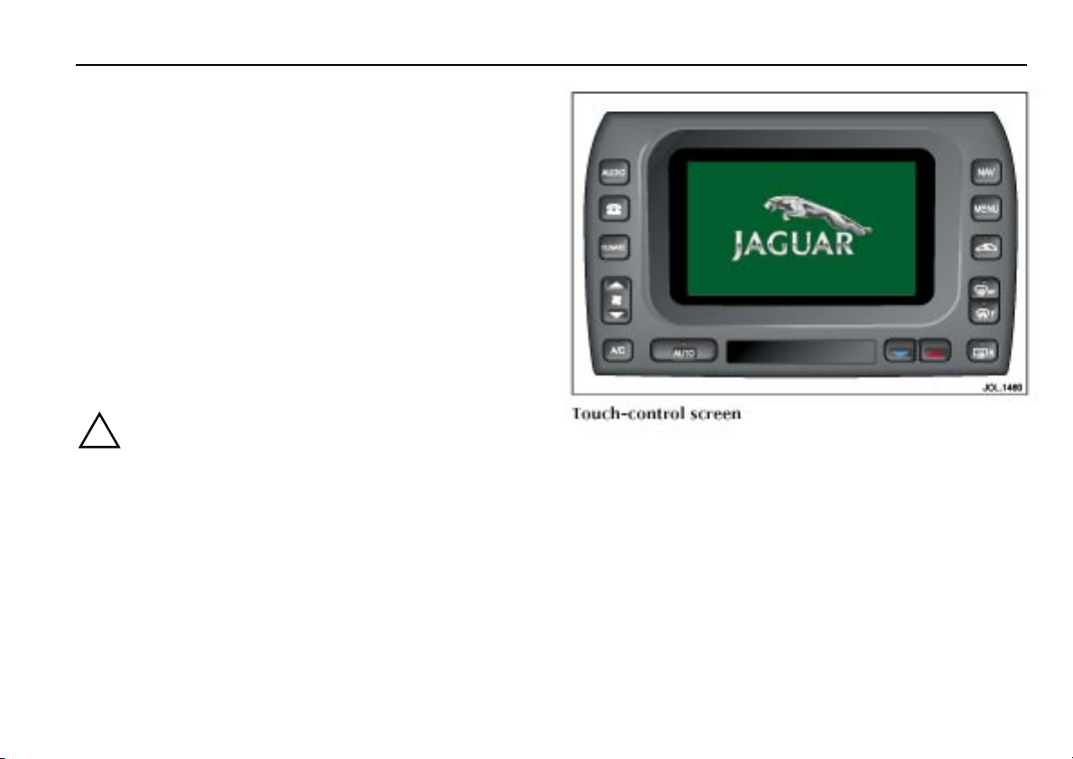
Touch-screen display
Touch-screen use and care
A touch-control screen is installed in certain vehicles and
provides touch-control of vehicle climate, audio, navigation,
television and telephone systems, as fitted. A small LCD screen
below the touch-control screen provides digital display of the
time, ambient temperature and vehicle cabin set temperature.
When the ignition switch is initially turned to position ‘I’ or ‘II’,
the touch-control screen will display the Jaguar logo screen
followed by activation and display of the mode previously used.
Display of touch-controls for other systems can be obtained by
pressing the appropriate perimeter button and these are
described in the appropriate Handbook. Climate control
operation is contained in Section 5 of this Handbook. Functions
of the ‘MENU’ button are described on the following pages.
!
!
WARNING:
WARNING:
In the interests of road safety, do not attempt to use the
In the interests of road safety, do not attempt to use the
touch-screen controls when driving.
touch-screen controls when driving.
Caution: Care m u s t be tak e n t o avoi d s p illin g o r spl a s h i ng
Caution: Care m u s t be tak e n t o avoi d s p illin g o r spl a s h i ng
drinks onto the screen. In the event of such an occurrence
drinks onto the screen. In the event of such an occurrence
advise your Jaguar Retailer.
advise your Jaguar Retailer.
Note: When op er at in g t ouch- sc re en co nt rols, al wa ys ex te nd th e
Note: When op er at in g t ouch- sc re en co nt rols, al wa ys ex te nd th e
tip of one finger, and withhold the thumb and remaining fingers
tip of one finger, and withhold the thumb and remaining fingers
from the screen.
from the screen.
The touch-screen and inner bezel must be kept clean to
The touch-screen and inner bezel must be kept clean to
maintain optimum performance. Finger marks and attracted
maintain optimum performance. Finger marks and attracted
dust should be regularly removed using a soft cloth and a Jaguar
dust should be regularly removed using a soft cloth and a Jaguar
approved cleaning agent.
approved cleaning agent.
Owner information 1-7
Page 13
1-8 Owner information
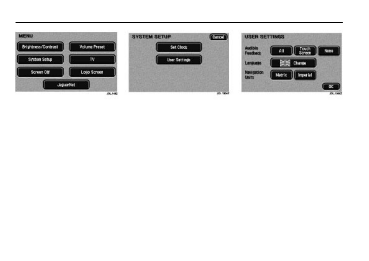
MENU
Pressing the ‘MENU’ perimeter button
will display the system menu screen.
The screen display can be blanked out by
touching the ‘Screen Off’ button.
Touch the screen, or any of the perimeter
system selection buttons, to restore the
display.
Alternatively, the Jaguar logo can be
displayed by touching the ‘Logo Screen’
button.
Note: ‘TV’ is only available in certain
countries. If TV is available, see the
accompanying Television Handbook for
user instructions.
SYSTEM SETUP
After touching the ‘System Setup’
button, the screen displays the touchcontrols for setting the clock,
and selecting user settings.
USER SETTINGS
After touching the ‘User Settings’
button, the screen displays the touchcontrols for the selection of audible
feedback, language, and units of
measurement.
‘All’ selects audible feedback on the
perimeter buttons and touch-controls.
‘Touch Screen’ selects audible feedback
on the touch-controls only.
‘None’ selects no audible feedback.
To select another language, touch the
‘Change’ button and, if the country is
not shown on the screen, scroll to the
desired country. To select a country,
touch the flag of the country required.
‘Navigation Units’ provides either
imperial or metric units for use with the
navigation system (where fitted).
Confirm your selection by touching ‘OK’.
Page 14
Owner information 1-9
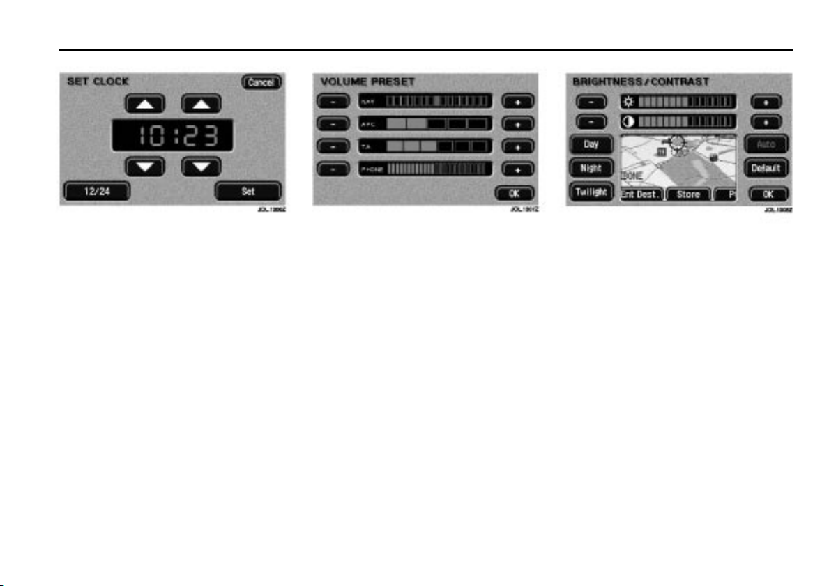
SET CLOCK
Clock adjustment is made by touching the
hour or minute, up or down arrow
button.
Touch the ‘12/24’ button to select twelve
or twenty four-hour display.
Note: For vehicles not fitted with the
touch-control screen, see the
accompanying Audio System Handbook
for the clock setting procedure.
Confirm your setting by touching ‘Set’.
VOLUME PRESET
After touching the ‘Volume Preset’
button, the screen displays the touchcontrols for adjustment of volume
associated with the navigation system,
phone, traffic announcements and
automatic volume control (AVC).
Adjustment of AVC varies the rate at
which volume is increased or decreased
relative to vehicle speed.
Touch and hold the plus or minus symbol
to adjust the volume of the selected
function.
Note: If any of the volume sliders are
adjusted to the fully ‘–’ position, then the
volume is turned fully off.
Confirm your selection by touching ‘OK’.
BRIGHTNESS/CONTRAST
After touching the ‘Brightness/Contrast’
button, the screen displays the touchcontrols for adjustment of the screen
display characteristics.
Touch the plus or minus symbol to adjust
the selected function.
Screen brightness and contrast can also
be dimmed for night driving. This is
achieved either manually via the ‘Day’,
‘Night’ or ‘Twilight’ touch-controls,
or automatically via selection of the
‘Auto’ touch-control and subsequent
operation of the vehicle exterior light
switch.
Touch the ‘Default’ button to restore the
default settings.
Confirm your selection by touching ‘OK’.
Page 15

Page 16

2 Security and locks
Security and locks 2- 1
Ignition switch
The ignition switch, on the right-hand
side of the steering column, has four key
positions:
0. Ignition OFF.
I. Auxiliary.
II. Ignition ON.
III. Engine start.
Position ‘0’: Is the only position in which
the key can be inserted and removed.
Position ‘I’: Allows use of some electrical
circuits, for example, radio operation.
The airbag system is activated in this
position.
Position ‘II’: All electrical circuits except
the starter motor are activated. The key
remains in this position when driving.
Position ‘III’: The starter motor is
operated.
To remove the ignition key
Manual transmission vehicles only
Apply the parkbrake and turn the key to
position ‘0’. The key can then be
removed from the switch.
Automatic transmission vehicles only
Automatic transmission vehicles have a
key interlock feature.
Apply the parkbrake, place the gear
selector in ‘P’ and turn the key to
position ‘0’.
The automatic transmission gear selector
must be placed in Park ‘P’ before the key
can be removed from the ignition switch.
When the key is removed, the gear
selector will be locked in Park.
Gear-shift interlock
A brake pedal/gear-shift interlock system
is incorporated in the automatic
transmission gear selector mechanism.
To move the gear selector from Park:
1. Turn the ignition key to position ‘II’ or
start the engine.
2. Press the brake pedal.
Steering column lock
When the ignition key is removed from
the ignition switch the steering column
lock is engaged. The lock is disengaged
when the key is inserted into the ignition
switch and turned to position ‘I’.
In rare circumstances it may be necessary
to gently turn the steering wheel from
side to side to release the steering column
lock.
Page 17

2-2 Security and locks
Vehicle security
When leaving the vehicle unoccupied,
remember the following:
• Apply the parkbrake and with
automatic transmission, move the
gear selector to Park ‘P’.
• Do not leave children or pets in the
vehicle unattended.
• Do not leave luggage or valuables on
view. Always take your valuables with
you or lock them in the luggage
compartment.
• Remove the ignition key and spare
keys, even when the vehicle is in your
garage.
• Close all windows and lock all doors
securely.
• Park the vehicle where it can be seen.
At night, park in a well-lit area.
Ensure that all key transmitters are
removed from the vehicle before locking
the doors, and that all doors, the luggage
compartment and the hood are closed.
It is important to keep your keys in safe
places at all times. Leaving them in
conspicuous places is an invitation for a
thief to steal them and, consequently,
your vehicle or belongings. Keep them as
secure as you would your wallet or purse,
both at home and away.
Immobilisation system security light
This vehicle is equipped with an
immobilisation system.
An electronic device is fitted in the head
of each key which is programmed to the
vehicle electronics. When the key is
placed in the ignition switch the vehicle
electronics recognise the correct key and
allow engine start. The engine cannot be
started with a key not programmed to the
vehicle electronic systems.
If an ignition key is placed in the ignition
switch and turned to position ‘II’ and the
alarm security light on the centre console
remains flashing after three seconds, it is
possible that the engine will not start.
In any event, please contact a Jaguar
Retailer to investigate the cause of the
light flashing.
Keys
The key, which is integrated with the
remote transmitter, operates all the locks
on your vehicle.
Vehicles are supplied with two key
transmitters.
Page 18
Security and locks 2- 3
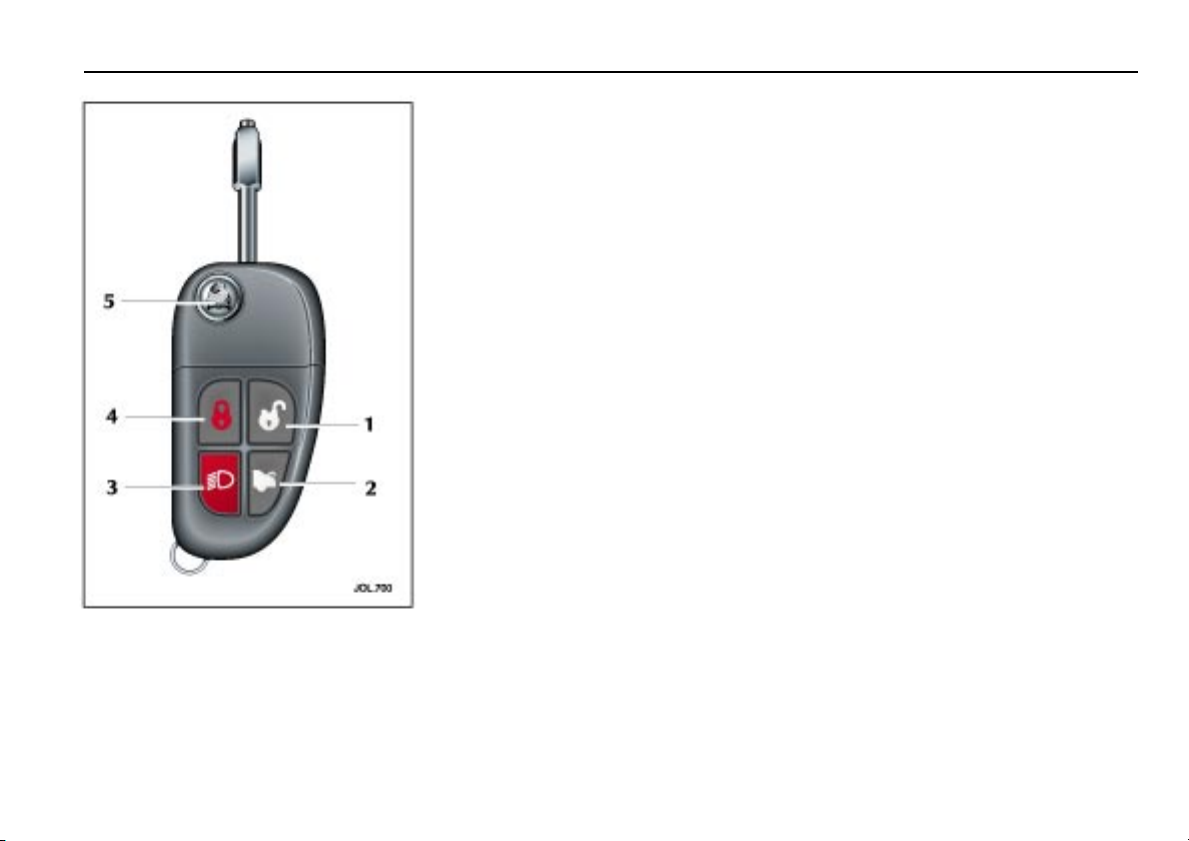
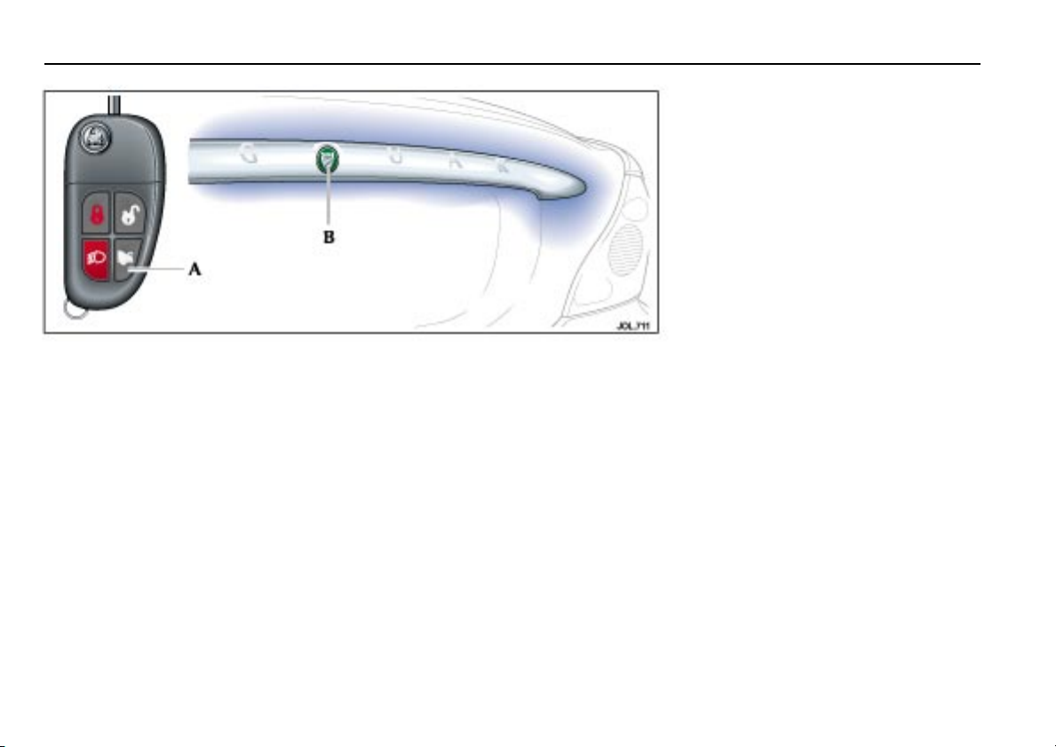
Key transmitter
The security system is controlled
remotely by a radio frequency, batteryoperated, integrated key transmitter.
The transmitter is activated by pressing
one of the operating buttons:
1. Unlocks and disarms the vehicle.
2. Releases luggage compartment lock.
3. Activates the convenience headlamp
feature and sounds the panic alarm.
4. Locks and arms the vehicle.
5. Lock/unlock the key.
To free the key, press the release
button (5). When not required press and
hold the button and fold the key into the
transmitter housing.
Note: Key transmitters will not operate if
a key is in the ignition switch.
Each integrated key will operate the
ignition switch, and lock the doors and
glove compartment.
The key number is recorded on a plastic
tag which is attached to each key. Detach
the tag and keep safely, not in the
vehicle.
Additional integrated key transmitters
can be obtained from your Retailer and
can be used provided a Retailer
programmes them all to the vehicle.
Caution: Should a key transmitter be
lost, a new one can be obtained and
programmed to the vehicle by a
Jaguar Retailer, who will ask for proof
of vehicle ownership. It is advisable
to notify a Retailer as soon as a key
transmitter is lost or stolen and have
the remaining key transmitter(s)
reprogrammed. This will then
prevent the lost or stolen key
transmitter from being used to
disarm and unlock the vehicle.
Note: Reta ilers keep a log of all enquiries
for replacement keys and notify
Jaguar Cars Ltd. of any such requests.
Care of key transmitters
The key transmitters must be treated with
care and not exposed to extremes of heat,
dust, humidity or be in contact with
fluids. Do not leave the transmitter
exposed to direct sunlight.
The battery is the only serviceable part.
Page 19
2-4 Security and locks
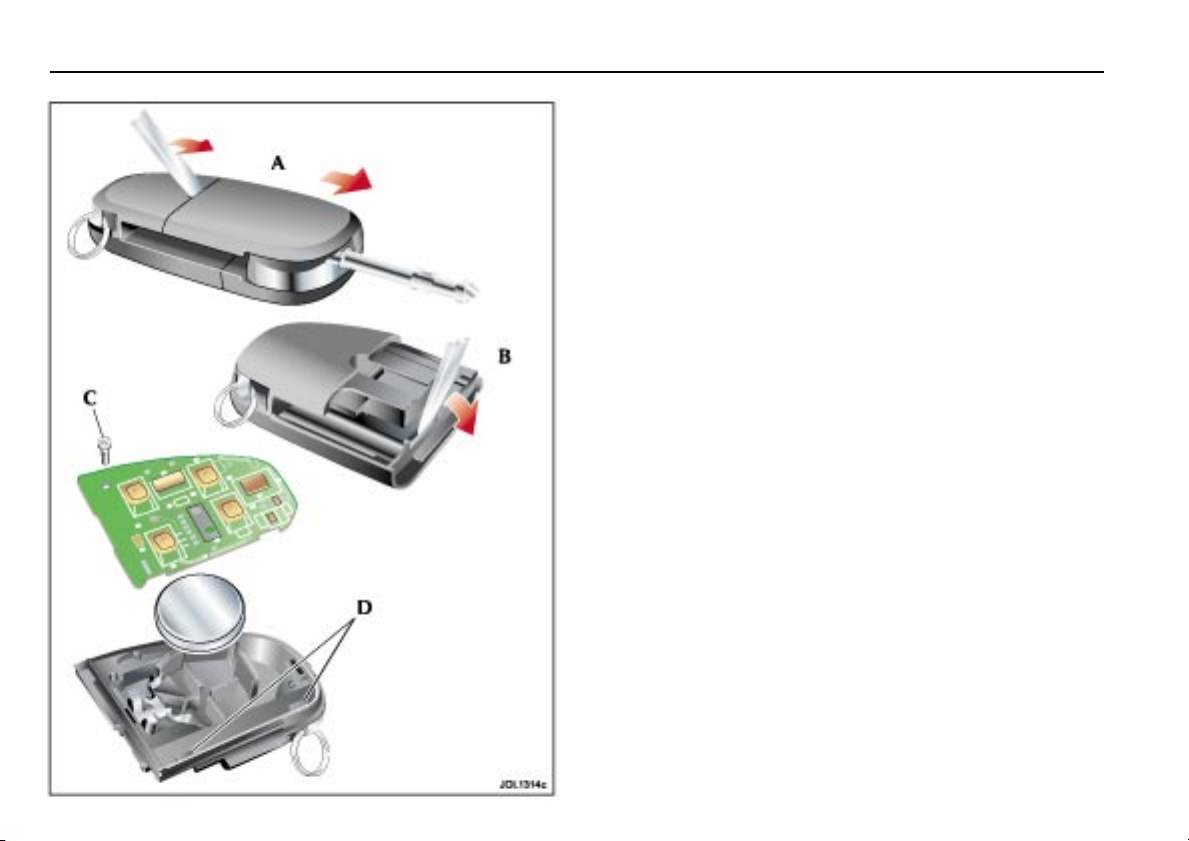
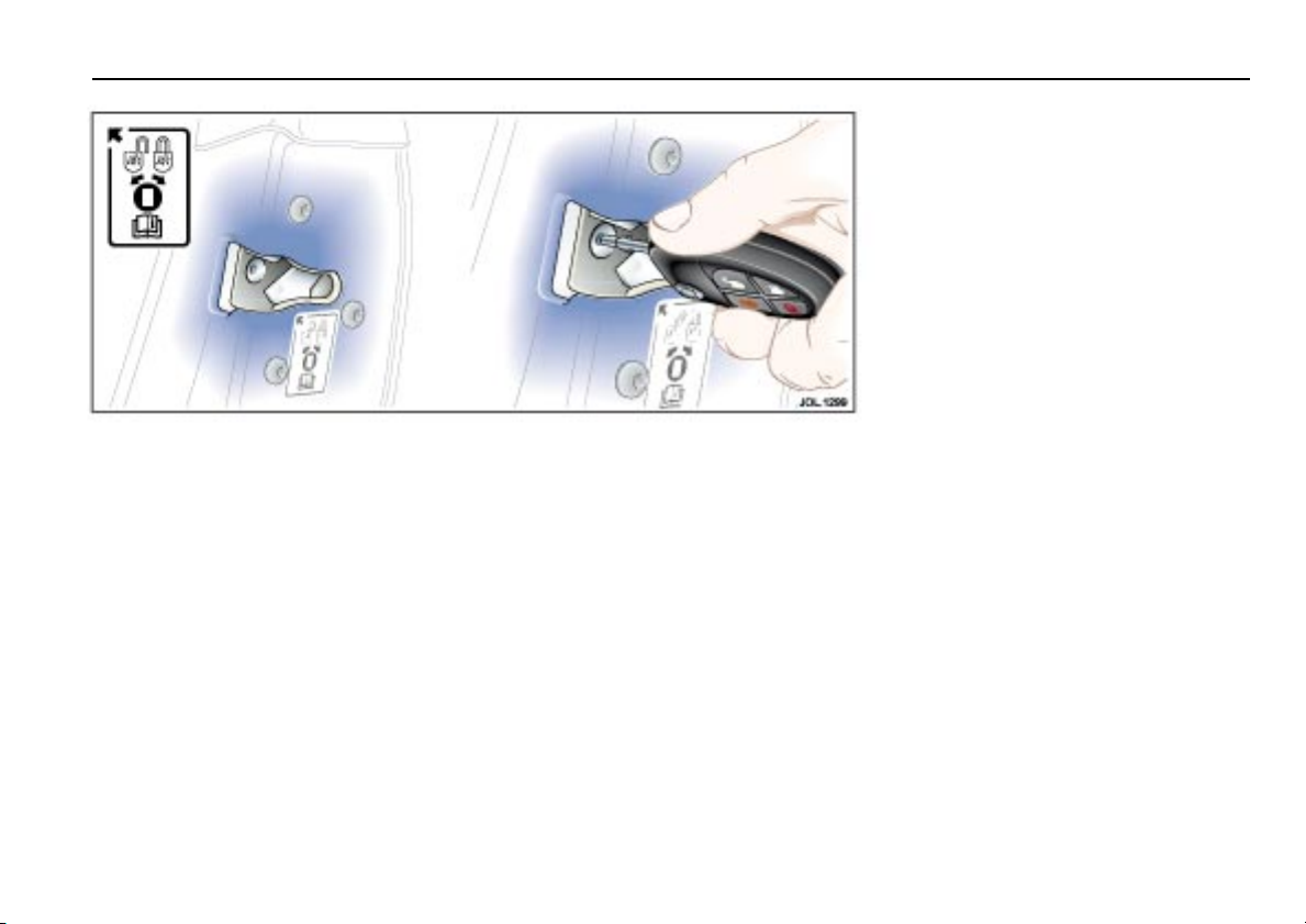
Key transmitter battery renewal
When the battery needs renewal there will be a significant
decrease in the effective range of the key transmitter.
A
To renew the battery, follow the procedure below:
• Insert a small, flat blade, screwdriver at an angle of about
45 degrees, into the slot on the back of the key transmitter
as shown (A). Apply light pressure to the screwdriver and
lever the screwdriver forward to separate the two halves of
the key transmitter. Pull the transmitter from the key body.
• Insert the screwdriver into the slot between the transmitter
covers adjacent to the key stowage area as shown (B).
Apply light pressure to the screwdriver and lever the
screwdriver downward to separate the covers.
• Unscrew and remove the small screw (C) and remove the
printed circuit board, taking care not to touch the battery
terminals. Remove the battery and dispose of it safely.
• Fit a new battery cell, type CR2032 (available from your
Jaguar Retailer), with the side marked with the positive
symbol (+) downwards in the battery receptacle.
Avoid touching the new battery as moisture/oil from the
fingers can reduce the life of the battery and corrode the
contacts.
• Replace the printed circuit board making sure to engage the
board under the securing tabs (D), and secure with the
screw.
• Refit the cover and click into place with thumb pressure.
• Slide the transmitter back onto the key body until it clicks
into place.
Page 20
Security and locks 2- 5
Door locks and handles
All doors can be locked and unlocked
either remotely using the key transmitter
buttons, or by using the integrated key.
Smart locking
This feature helps prevent locking the key
in the vehicle. If one of the front doors is
open and an attempt is made to lock the
doors using a door interior locking lever,
all doors will become unlocked.
If a door, hood or luggage compartment is
op en, t he vehi cle can only b e locke d fr om
the outside by using a key in the driver’s
door lock.
It will not be possible to lock the vehicle
with a key transmitter if a door, luggage
compartment or hood is open.
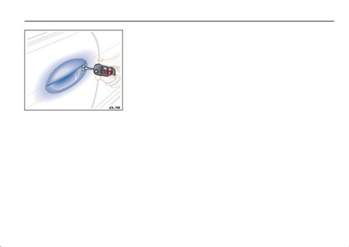
Vehicle locking and unlocking
To lock the vehicle and set alarm
• Press the lock button on the key
transmitter, or;
• Put the key in the driver’s door lock,
turn the key towards the rear of the
vehicle and release.
The direction indicators will flash once,
the security light on the centre console
will start flashing and, after 20 seconds,
the alarm will be set.
If a door, the hood or the luggage
compartment lid are open and an attempt
is made to lock the vehicle, the direction
indicators will flash five times and the
horn will chirp twice as a warning that
the vehicle is not secure.
Note: Ensure that the manually operated
rear windows are closed.
To unlock the vehicle and disarm the
alarm system
Using a key
• Put the key in the driver’s door lock,
turn the key towards the front of the
vehicle and release.
Single stage unlocking – This unlocks
all doors and the luggage compartment
and turns on the interior lights.
Two stage unlocking – This only
unlocks the driver’s door and luggage
compartment and turns on the interior
lights. A second turn of the key is
required to unlock all doors.
Using a key transmitter
• Press the unlock button on the key
transmitter.
Single stage unlocking – This unlocks
all doors and the luggage compartment
and turns on the interior lights.
Two stage unlocking – This only
unlocks the driver’s door and luggage
compartment and turns on the interior
lights. A second press is required to
unlock all doors.
Page 21
2-6 Security and locks
Direction indicator unlock alerts
The exterior direction indicators give two
flashes as unlocking takes place.
Selecting single stage or two stage
unlocking
The procedure for changing from single
stage to two stage unlocking, or vice
versa, is as follows:
• Press and hold the lock and unlock
buttons on the key transmitter
simultaneously for four seconds.
To revert to the previous condition,
repeat the procedure described above.
Global closing
!
WARNING:
Ensure that all occupants are kept
clear of the windows and sunroof
aperture.
Place a key in the driver’s door lock, turn
the key towards the rear of the vehicle
and hold in this position for longer than
1½ seconds to close all the electrically
operated windows (and sunroof, if fitted).
Note: Ensure that manually operated
rear windows are fully closed by hand
(if fitted).
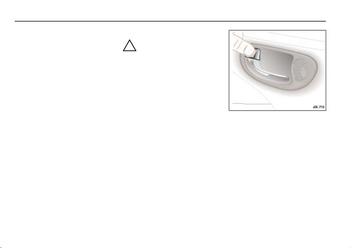
Internal door locking and unlocking
To centrally lock all doors, press the lock
lever on the driver’s or front passenger’s
door.
To lock a rear door, press the lock lever.
To unlock a front door, pull the release
handle or the lock lever.
To unlock a rear door, pull the lock lever.
The driver’s or front passenger’s door
lock lever will unlock all doors.
Page 22
Security and locks 2- 7
Auto-relocking
Note: This feature is normally disabled.
A Jaguar Retailer can enable this feature,
if required.
This feature automatically centrally locks
and arms the vehicle if the vehicle has
been unlocked with the key transmitter:
• and no door has been opened for
45 seconds or,
• if the ignition remains off for
45 seconds.
Child safety locks
Child safety locks are fitted to the rear
doors.
Open a rear door, insert the ignition key
into the lock and turn the key outwards.
This immobilises that door interior
handle. Repeat this for the opposite rear
door.
After setting the child lock the door(s) can
only be opened using the exterior door
handle.
To remove the child lock feature, open
the door and using a key, move the
control to its original unlock position.
Drive-away door locking
With the ignition key at position ‘II’ and
all doors closed, all doors will lock when
the vehicle is moving above 5 mph
(8 km/h). If the vehicle is stopped and a
door is opened, provided the engine
remains running, the car will relock when
the door is closed and the vehicle is
moving. If the car is unlocked this feature
will only lock the doors again if the
ignition is turned off and then back on.
All vehicles have the drive-away door
locking feature installed during
manufacture. This feature can be
disabled, or reinstated, by a Jaguar
Retailer, if required.
Page 23
2-8 Security and locks
Luggage compartment
To open the luggage compartment:
• Press the luggage compartment
button (A) on the key transmitter or,
• With the vehicle unlocked, press the
release button (B) on the
compartment lid.
If the vehicle alarm system is armed and
the luggage compartment is opened using
the key transmitter the alarm will not
sound. The system will be rearmed when
the lid is closed, provided the vehicle has
not been disarmed.
Page 24
Security and locks 2- 9
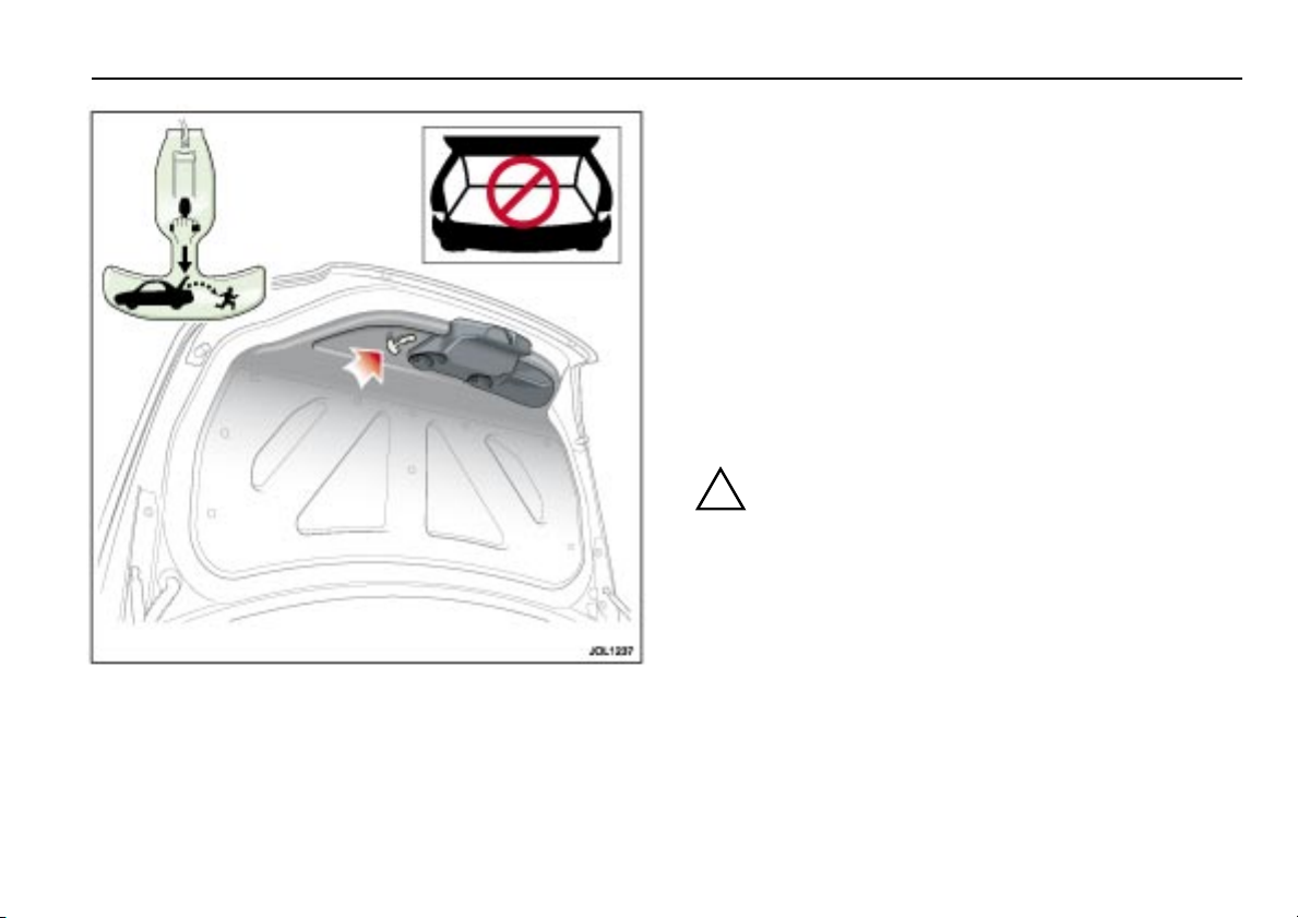
Luggage compartment emergency release
Your vehicle is equipped with a mechanical interior luggage
compartment release handle that provides a means of escape
for children and adults in the event they become locked inside
the luggage compartment.
Adults are advised to familiarise themselves with the operation
and location of the release handle.
To open the luggage compartment lid from the inside, pull the
illuminated ‘T’-shaped handle and push up the trunk lid.
The material that the handle is made of will glow for hours in
the darkness of the luggage compartment following brief
exposure to ambient light.
The ‘T’-shaped handle is located on the luggage compartment
door lid.
!
WARNING:
1. Keep vehicle doors and the luggage compartment
locked and keep keys out of a child’s reach.
Unsupervised children could lock themselves in an
open trunk and risk injury. Children should be taught
not to play in vehicles.
2. On hot days, the temperature in the luggage
compartment and vehicle interior can rise very
quickly. Exposure of people or animals to these high
temperatures for even a short time can cause death or
serious heat-related injuries, including brain damage.
Small children are particularly at risk.
Page 25

2-10 Security and locks
Alarms and audible
signals
Note: In certain markets, legislation
prohibits the use of audible confirmation
signals. In such cases, the sound source
has been removed from the system.
Audible signals
Two horn chirps will sound if an attempt
is made to lock the vehicle with the key
transmitter if a door, the hood or the
luggage compartment is not fully closed.
Error signal
The direction indicators will flash five
times whenever one of the following
conditions is present:
• If any door is open when an attempt is
made to lock the vehicle.
• The luggage compartment or the hood
is not properly closed when an
attempt is made to lock the vehicle.
Full alarm
Once armed, any of the following
circumstances will create a full alarm
state, sound the horns and flash the
direction indicators:
• Opening a door, luggage
compartment or hood.
• Using a key in the ignition switch
which is not programmed to the
vehicle.
• Any attempt is made to remove the
radio.
Page 26

Security and locks 2-11
Security features
The security system has been designed
for:
• Prevention of theft of the vehicle.
• Prevention of theft of items from the
vehicle.
• Personal security.
The security system is integrated with the
vehicle electronics and engine
management systems making it far more
difficult for a thief to penetrate and steal
the vehicle.
Battery reconnection
If the battery has been disconnected and
is subsequently reconnected, the alarm
system will resume the same state as
before the battery was disconnected.
If the alarm was sounding when the
battery was disconnected it will sound
again when the battery is reconnected
and will need:
• The transmitter unlock button to be
pressed or,
• Key placed in the ignition switch and
turned to position ‘I’ to disarm it or,
• Unlock the vehicle from the driver’s
door with a key.
Panic alarm
When in or near the vehicle, the alarm
can be set off to deter a possible offender.
For this feature to operate, the key must
not be in the ignition switch.
Pressing the headlamp convenience/panic
button on the key transmitter three times
within three seconds will activate the
‘Panic Alarm’.
The alarm is stopped by:
• Putting the key into the ignition
switch and turning to position ‘II’ or,
• Pressing either the transmitter panic
button three times or one press of the
unlock button, or,
• Unlocking the vehicle from the
driver’s door with a key.
Radio frequency
The radio frequency remote system
operates on a frequency subject to USA
Federal Communications Commission
(FCC) rules.
The device complies with Part 15 of the
FCC rules and RSS–210 of the Industry
Canada. Operation is subject to the two
following conditions:
1. The device may not cause harmful
interference.
2. This device must accept any
interference received, including
interference that may cause undesired
operation.
The key transmitter radio frequency
approval numbers for the USA and
Canada are as shown below.
USA – NHVWB1U241.
Canada – 3495 103 2304.
Note: The manufacturer is not
responsible for any radio interference or
TV interference caused by unauthorised
modifications to this equipment. Changes
or modifications not expressly approved
by the party responsible for compliance
could void the user’s authority to operate
the equipment.
Caution: The key-ring transmitter
may suffer interference from other
legal users of this radio frequency
band, such as radio amateurs,
medical equipment, remote controls
or alarm systems. To lock or unlock
the vehicle either use a key or
operate the key-ring transmitter as
close to the security antenna as
possible.
Page 27
2-12 Security and locks
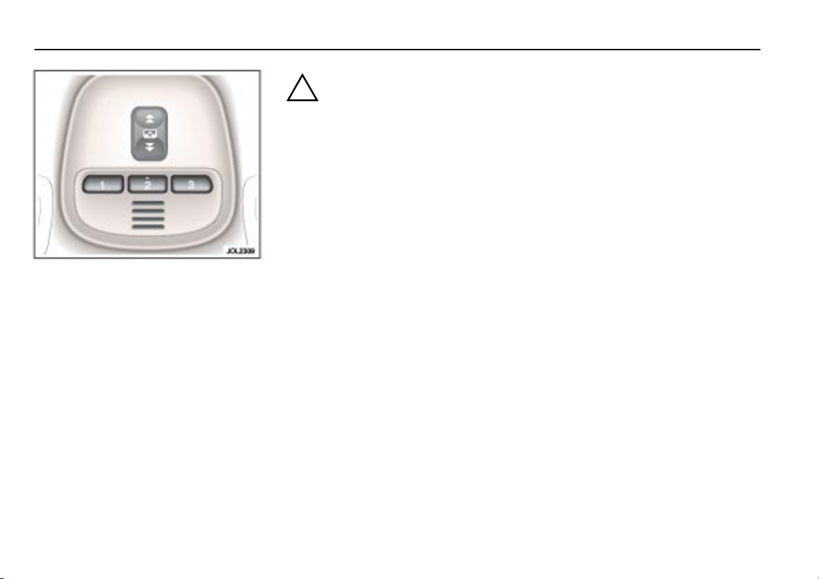
HomeLink® Universal
Transceiver
The HomeLink® Universal Transceiver is
fitted in the roof console. The transceiver
can be programmed to transmit the radio
frequencies of up to three different
transmitters used to activate garage
doors, gates, home lighting, security
systems, or other radio frequency
operated devices.
If you would like additional information
on the HomeLink
compatible products or to purchase other
accessories such as the HomeLink
lighting package, contact your Jaguar
Retailer, or HomeLink at
1–800–355–3515 or on the Internet at
www.homelink.jci.com.
®
Universal Transceiver,
®
!
WARNING:
1. Do not use the transceiver with
any garage door opener that lacks
the safety stop and reverse feature
as required by federal safety
standards. A garage door opener
which cannot detect an object,
signalling the door to stop and
reverse, does not meet current
federal safety standards. Using a
garage door opener without these
features increases risk of serious
injury or death.
2. When programming the
transceiver to a garage door
opener or entry gate, make sure
that people, the vehicle and
objects are out of the way to
prevent potential harm or damage
as the gate or garage door will
activate during the programme.
Programming
Note: For best results, fit a new battery to
the hand-held transmitter of the garage
door opener (or other device) before
programming. If your garage door opener
receiver (located in the garage) is
equipped with an antenna, ensure that the
antenna is hanging straight down.
1. Switch off the engine.
2. Press and hold the two outermost
buttons (1 and 3) on the transceiver,
releasing only when the indicator light
begins to flash after 20 seconds.
Note: Do not repeat step 2 when
programming the additional buttons.
3. Hold the end of the hand-held
transmitter approximately 1
to 3 inches (2.5 to 7.5 cm) away from
the transceiver in the roof console,
keeping the indicator light in view.
4. Using both hands, simultaneously
pus h t he ha nd -h eld t ra ns mi tt er bu tt on
and the chosen transceiver button (1,
2 or 3). The transceiver indicator light
will flash, first slowly and then rapidly.
When the indicator light flashes
rapidly, release both buttons.
The rapid flashing light indicates
successful programming of the
frequency signal.
Page 28

Security and locks 2-13
5. Press and hold the programmed
transceiver button to activate the
programmed device and release when
the device begins to activate.
6. If, after 90 seconds, the indicator light
does not f lash rapidly, release both th e
transceiver and the hand-held
transmitter buttons and repeat the
procedure starting with Step 2.
However, position the hand-held
transmitter at a different angle and/or
distance.
7. The device must now be ‘trained’ for
operation from the transceiver.
See Training procedure on
page 2-14.
Programming hints and tips
If the device does not operate you may
need to complete the steps outlined in
the section Rolling code
programming.
Some entry gates and garage door
openers may require you to replace
Step 4 with the procedures in the
section Canadian programming/
Gate programming.
If you are programming a rolling code
equipped device, continue with the
procedures outlined in the section
Rolling code programming.
Note: Keep the original transmitter for
future use or programming procedures if,
for example, you purchase a new vehicle.
Caution: It is recommended that
when you sell or dispose of the
vehicle, the programmed transceiver
buttons be erased for security
purposes.
Canadian programming/
Gate programming
Canadian frequency laws, and the
technology of some entry gates, require
you to press and re-press (cycle) the
hand-held transmitter button every two
seconds during programming.
Continue to press and hold the desired
transceiver button while you cycle your
hand-held transmitter until the indicator
light flashes rapidly.
Note: When programming a garage door
opener or entry gate, unplug the device
during the ‘cycling’ process to prevent
possible motor failure.
Rolling code programming
Rolling code garage door openers
(or other rolling code devices) which are
‘code protected’ may be determined by
the following:
• Reference the device owner’s
instruction manual for verification.
• The hand-held transmitter appears to
programme the transceiver correctly,
but does not activate the garage door.
• Press and hold the programmed
transceiver button. The device has the
rolling code feature if the transceiver
indicator light flashes rapidly and
then turns solid after two seconds.
To programme a garage door opener or
other device with the rolling code feature,
follow these steps after completing the
section Programming.
Page 29

2-14 Security and locks
Training procedure
Note: The aid of a second person may
make the following training procedure
quicker and easier.
1. Locate the training button on the
garage door opener receiver (or other
device). Exact location and colour of
the button may vary. If there is
difficulty locating this button, refer to
the instruction manual supplied with
the device.
Note: Following step 2 there are
30 seconds in which to initiate step 3.
2. Firmly press and release the training
button on the receiver which will
activate the training light.
3. Firmly press and release the
transceiver button. Press and release
the transceiver button a second time
to complete the training process.
Some devices may require you to do
this step a third time to complete the
training.
The device should now recognise the
transceiver signal and activate when the
transceiver button is pressed.
The remaining buttons may now be
programmed if this has not been
previously done.
Reprogramming a transceiver button
To programme a device using a button
that has previously trained, follow these
steps:
1. Press and hold the desired transceiver
button. Do not release until step 4 has
been completed.
2. When the indicator light begins to
flash slowly (after 20 seconds),
position the hand-held transmitter
1to3inches (2.5to7.5cm) away
from the transceiver surface.
3. Press and hold the hand-held
transmitter button.
4. The transceiver indicator light will
flash, first slowly and then rapidly.
When the indicator light begins to
flash rapidly, release both buttons.
The previous device has now been erased
and the new device can be activated by
pushing the transceiver button that has
just been programmed. This procedure
will not affect any other programmed
transceiver buttons.
Erasing programmed transceiver
buttons
Individual buttons cannot be erased,
however, to erase all three programmed
buttons:
1. Press and hold the two outermost
buttons until the indicator light begins
to flash after 20 seconds.
2. Release both buttons.
The transceiver is now in the train, or
learning, mode and can be programmed
at any time following steps 3 and 4 in the
section Programming.
!
WARNING:
The manufacturer is not responsible
for any radio or TV interference
caused by unauthorised
modifications to this equipment.
Such modifications could void the
user’s authority to operate the
equipment.
Page 30

Approvals for radio transceiver
Country Approval No.
USA CB2JAGHL3
Security and locks 2-15
Page 31

Page 32

3 Before driving
Occupant protection
Seat belts
The use of front and rear seat belts is
mandatory in most countries. Using seat
belts saves lives. They should be worn by
all occupants whenever the vehicle is in
use, for maximum protection.
This vehicle has an individual lap/
shoulder inertia reel seat belt for each
occupant.
The inertia operating mechanism of the
seat belts allows the wearers to move
their upper bodies to reach various
controls. The seat belts will lock
automatically with accelerated body
movement or in the event of emergency
braking. Both front seat belts are
equipped with pretensioners to assist
restraint and safety belt force limiters to
help minimise the risk of upper body
injuries.
Seat belt height adjustment is provided
for driver and front seat passenger to
ensure that the seat belt webbing can be
positioned to pass over the shoulder
without pulling against the neck. It can be
locked in any of five positions.
Seat belt fitting
!
WARNING:
Do not adjust the seat belt while
driving.
Draw the tongue of the seat belt over the
shoulder, across the chest and push it
into the buckle unit slot. A positive ‘click’
indicates that it is safely locked.
The use of comfort clips or devices that
would create slackness in the seat belt
system are not recommended.
Before driving 3- 1
Always ensure that the webbing is
midway between the neck and the edge
of the shoulder. Correct tension is
controlled by automatic retraction of the
reel.
A warning light on the instrument panel
comes on for 60 seconds when the
driver’s seat belt is not fastened and a
warning signal sounds for six seconds.
Note: If the vehicle is parked on unlevel
ground, the seat belt mechanism may
lock. This is not a fault, gently ease the belt
from its attachment to unlock it.
Page 33

3-2 Before driving
Front belt height adjustment
To operate: Press the locking button and
slide the anchorage point to the required
position to ensure comfort and safety.
Release the button and check that the
anchorage point is locked.
Always check the anchorage point after
the seat has been adjusted to ensure that
the belt is correctly positioned.
Inertia reel mechanism check
Static test: Whilst seated, fasten the seat
belt and grip the shoulder belt at
approximately shoulder level with the
opposite hand. Pull the belt sharply
downwards, the belt should lock.
Road test: The following road test must
be carried out only under maximum safe
road conditions.
With the seat belt correctly fitted to the
driver and passenger(s), drive the vehicle
at 5 mph (8 km/h) and, ensuring that it is
safe to do so, brake sharply.
The seat belt(s) should lock automatically,
holding both driver and passenger(s)
securely in position.
It is important when braking that the
reactions of both driver and passenger(s)
are normal, that is, the body must not be
thrown forward in anticipation, thus
causing a snatching action of the belt
which would operate the locking
mechanism.
If the belt fails to lock on either test,
consult a Jaguar Retailer.
Page 34

!
WARNING:
1. Seat belts are designed to bear
upon the bony structure of the
body. The lap section of the belt
must be worn low across the front
of the pelvis and NOT across the
abdominal area. Always ensure
that the webbing is midway
between the neck and the edge of
the shoulder.
2. Care should be taken to avoid
contamination of the webbing
with polishes, oils and chemicals,
and particularly battery acid.
Cleani n g may s a f e ly be c a r ried o u t
using mild soap and water.
If webbing becomes frayed,
contaminated or damaged,
discard it and fit a new seat belt.
Before driving 3- 3
3. It is essential to renew the entire
assembly after it has been worn in
a severe impact even if damage to
the assembly is not obvious.
4. Belts should not be worn with the
webbing twisted.
5. Each seat belt assembly must only
be used by one occupant; it is
dangerous to put a seat belt
around a child being carried on
the occupant’s lap.
6. No modifications or additions
should be made by the user which
will prevent the seat belt adjusting
devices from operating.
7. Should the seat belt not retract
and remain at its static length,
consult your nearest Jaguar
Retailer immediately.
Page 35

3-4 Before driving
Advanced occupant restraint
system
In order to provide optimum protection
this vehicle is equipped with front and
side airbags for driver and front seat
passenger. These are supplemental
restraint systems which are used in
conjunction with the seat belts to help
protect the driver and front seat
passenger from upper body and head
injuries.
An alert label on the front face of the
driver’s and passenger’ s sun visor directs
you to read the warning label on the rear
face of each sun visor.
The warning label contains the following
statement:
!
WARNING:
DEATH or SERIOUS INJURY can
occur.
• Children 12 and under can be
killed by the airbag.
• The BACK SEAT is the SAFEST
place for children.
• NEVER put a rear-fa cing child seat
in the front.
• Sit as far back as possible from
the airbag.
• ALWAYS use SEAT BELTS and
CHILD RESTRAINTS.
To do their life-saving job, airbags open
with a great deal of force and this force
can pose a potentially dangerous risk in
some situations, particularly when a front
seat occupant is not properly restrained
with the seat belt.
Because airbags must inflate rapidly and
with considerable force, there is the risk
of death or serious injuries such as
fractures, facial and eye injuries or
internal injuries, particularly to occupants
who are not properly restrained or sitting
correctly at the time of the airbag
deployment.
Airbags do not inflate slowly or gently
and the risk of injury from a deploying
airbag is greatest close to the trim
covering the airbag.
The whole sequence of events from
sensing the impact to full inflation of the
bag takes place in a fraction of a second.
The driver airbag is located in the centre
of the steering wheel and the front seat
passenger airbag is located in the fascia
panel immediately in front of the
passenger seat.
The side airbags are fitted within the
driver and front passenger seat outboard
seat bolsters, and are identified by a label
on the seat.
Page 36

Before driving 3- 5
Curtain airbags are fitted above the
doors, under the headlining.
These deploy downwards to give
protection to the heads of driver, front
seat passenger and the outer rear seat
occupants.
The airbag warning light in the
instrument cluster will be lit for
approximately six seconds when the
ignition is turned on. If the light remains
on or flashes it indicates a fault within the
airbag electrical circuits. Report the fault
to a Jaguar Retailer immediately.
It is safe to drive the vehicle; however,
in an accident the airbags may not
operate.
!
WARNING:
1. No objects whatsoever should be
attached to the centre cover of the
steering wheel, the passenger
fascia panel or the sides of the
driver and front passenger seats.
Do not put anything on or over
the airbag inflation area. Placing
objects on or over the airbag
inflation area may cause those
objects to be propelled by the
airbag into your face and torso
causing serious injury.
2. Safety experts recommend a
minimum distance of at least
10 inches (25.4 cm) between an
occupant's chest and a front
airbag.
3. Chi l d r e n 12 yea r s o ld an d y o u n g e r
can be killed or seriously injured
by the airbag. The rear seat is the
safest place for children.
4. Several airbag system components
get hot after inflation. Do not
touch them after they have
deployed.
5. To ensure that the side airbags are
fully effective:
DO NOT sit too close to, or lean
against the door trim. The side
airbag could injure you as it
deploys from the side of the seat.
DO NOT lean out of the window
aperture.
Only use JAGUAR APPROVED
accessories (e.g. seat covers).
Due to the function of the
CURTAIN AIRBAG deployment,
CONSULT your Jaguar Retailer
prior to installing any
ACCESSORIES in the upper
environment/pillar trim area
(e.g. HANDS-FREE TELEPHONE
KITS).
6. If an airbag is inflated, the airbag
will not function again and must
be rene we d im m ediately. If a new
airbag is not fitted, the unrepaired
area wil l i ncre a s e t he ri s k o f inj u r y
in a collision.
Airbag warning information is printed on
the driver’s and passenger’s sunvisor.
Ai rbag wa rni ng light information i s sh own
in Section 4.
Page 37

3-6 Before driving
Page 38

Before driving 3- 7
!
WARNING:
Driver and front seat passenger
should always move their seats as far
rearwards as is practical.
Ideally, drivers should sit with at least
10 inches (25.4 cm) between the centre
of their breastbone and the cover of the
steering wheel airbag.
Since the risk zone at the time of
deployment is the first 2 to 3 inches
(5.4 cm – 7.5 cm) from the airbag cover,
sitting back 10 inches (25.4 cm) provides
a clear margin of safety. Very few drivers
are unable to achieve and maintain that
safety gap.
The vast majority of drivers who do not
now sit that far back can change their
position and achieve that distance:
• Move your seat back as far as you can
while still comfortably reaching the
pedals.
• Recline the back of your seat one or
two notches from the upright
position. If reclining the back of your
seat makes it hard to see the road,
raise the seat.
• Tilt the steering wheel/column
downwards so as to point the airbag
at your chest instead of your head and
neck. Adjust the steering wheel/
column fore/aft so that it extends
towards the driver as little as possible,
ensuring that the airbag has plenty of
room to deploy.
!
WARNING:
Do not attempt to service, repair or
modify the airbag system or its fuses.
All work on the airbag system,
including renewal after deployment
and renewal at the end of its service
life, must be carried out by an
authorised Jaguar Retailer.
In the event of the vehicle being
dismantled, airbag module removal and
disposal MUST be made by a qualified
person. Instructions can be obtained
from an authorised Jaguar Retailer.
The noise and gas associated with the
deployment of the airbags is not injurious
to health.
After airbag deployment, it is normal to
notice a smoke-like, powdery residue or
smell the burnt propellant. This may
consist of cornstarch, talcum powder or
sodium compounds that result from the
combustion process that inflates the
airbag.
Small amounts of other chemicals may be
present which may irritate the skin and
eyes, but none of the residue is toxic.
While the system is designed to help
reduce serious injuries, it may also cause
minor burns, abrasions, swelling or
temporary hearing loss.
Page 39

3-8 Before driving
Front airbags
The front airbags use a dual inflation technology and are
designed to activate when the vehicle suffers a frontal impact of
sufficient force to cause the sensors to close an electrical circuit
that initiates airbag inflation. Front airbags use a dual inflation
technology which means that, if activated, the bag(s) will deploy
at one of two levels of inflation.
Sensors monitor the weight on the front passenger seat.
The proximity of the driver to the steering wheel is also sensed.
In the event of a collision, the advanced restraint system makes
the decision to activate the appropriate airbags, the required
inflation level and trigger the seat belt pretensioners.
Occupancy sensing
The front passenger seat is equipped with an occupancy sensor.
The sensor measures the weight on the cushion and changes the
passenger airbag deployment status.
The occupancy sensor operates as follows:
Seat occupancy status
Completely empty Deactivated No*
Low weight occupant/
object
Heavy occupant/object Activated No
* It is possible to receive an intermittent warning light with an
empty seat condition. This is part of the system’s adaptive
behaviour, and does not affect the status of the passenger
airbag. However, if the warning light becomes permanently
illuminated when the seat is definitely empty, then contact your
nearest Jaguar Retailer immediately.
The airbag warning light is located on the passenger fascia.
Passenger
airbag status
Deactivated Yes
Warning light
active
Page 40

With the driver’s and front passenger’s
airbag, the occupant, restrained by the
seat belt, moves forward, the head and
chest come into contact with the inflated
bag. The airbags which then deflate
rapidly, in a controlled manner, via vent
holes, absorb the remaining energy of the
impact.
If the airbags do not inflate in a collision
it does not mean that something is wrong
with the system.
Rather, it means the forces of the impact
were not of the type sufficient to cause
activation. Front airbags are designed to
inflate in frontal and near frontal
collisions, not roll-over, side-impact or
rear-impact.
In circumstances where the airbags are
not deployed, protection is provided by
the seat belts. The severity of the collision
is a function of the relative speed and
weight of the vehicles or objects colliding.
Thus, it is extremely important that
occupants be properly restrained as far
away from the airbag as possible while
maintaining vehicle control.
Before driving 3- 9
Page 41

3-10 Before driving
Side protection
The side protection system utilizes
four airbags: Two seat mounted in the
front seats, and two curtain airbags
located in the upper environment just
above the door opening.
When the seat mounted side airbag,
inflates upon a vehicle side impact,
it breaks through the seat bolster
stitching, protecting the side of the rib
cage of the driver or front seat passenger.
When the curtain airbag inflates upon a
vehicle side impact, it breaks through the
headlining and deploys downwards,
giving head protection to front and rear
seat occupants.
The airbags, in combination with the seat
belts, can help reduce the risk of severe
injuries in the event of a significant side
impact collision.
In certain lateral collisions, the airbags on
the side affected by the collision will be
inflated even if the respective seat is not
occupied.
Seat mounted side and curtain airbags are
designed to inflate in a side impact
collision, not rollover, rear-impact,
frontal or near-frontal collisions, unless
the collision causes sufficient lateral
deceleration.
Page 42

Child safety
JAGUAR CARS LTD. STRONGLY RECOMMEND THAT AT ALL TIMES
CHILDREN SHOULD BE CARRIED IN THE REAR SEATS.
!
WARNING:
Children must be restrained by a child safety restraint that
is suitable for their weight and size.
In many countries legislation governs how and where children
should be carried when travelling in a vehicle. It is the
responsibility of the driver to comply with all regulations in
force in the country where the vehicle is being used.
Before driving 3- 11
!
WARNING:
DO NOT install a rearward-facing child seat in the front
passenger seat position since deployment of the
passenger fascia airbag could cause death or serious injury
to the child.
This is emphasised by the label displayed on the end of
the fascia on the front passenger side (see above).
If however, you have no alternative but to place a child in
the front passenger seat, use only a forward facing child
seat with the passenger seat set fully rearward and in its
lowest position. Always follow the fitting instructions
supplied with the appropriate child restraint system.
Page 43

3-12 Before driving
Holding a baby or child in a person’s
arms is not a substitute for a child
restraint system. Do not use a seat belt to
restrain more than one person.
In an accident, a baby or child held in a
person’s arms can be crushed between
the vehicle’s interior and a restrained
person.
The child can also be injured by hitting
the interior or by being thrown from the
vehicle during a sudden manoeuvre or
impact.
Injury can also be caused if the baby or
child is allowed to ride on the seat
unrestrained. Other occupants should
also be properly restrained to help reduce
the chance of injuring the child.
Do not allow children to stand in the
space between the seats, or on the
passenger seats.
!
WARNING:
1. Do not t r y to put a n adult s e a t belt
around two children.
2. Choose a child seat that sits
securely on the seat cushion and
against the seat back.
Choosing a suitable child seat
Before you buy a child seat, it is
important to note that your child’s
weight, rather than age, determines the
type of seat that is required.
Jaguar recommends that a rearfacing seat with a harness is used for
as long as your infant’s development
allows. Do not use a forward-facing seat
until your child is able to sit up unaided.
Up to the age of 2, a child’s spine and
neck are not sufficiently developed to
avoid injury in a frontal impact.
Always use the top tether to secure a
forward facing child seat where
possible (refer to page 3 - 17).
When choosing a child seat, it is also
important to consider how you plan to
use it. For longer journeys, a reclining
seat may offer added comfort and
support for a sleeping child, while a
light-weight design may be easier to lift in
and out of the vehicle. It is also worth
noting that some children are more
suited to a harness-style seat than a
booster seat during their toddler years.
Because child seats vary in shape, certain
designs may be more stable when
mounted on the outer rear seating
positions, rather than in the centre.
Always check that the child seat can be
mounted securely in the required
position: if in doubt, speak to your Jaguar
Retailer.
We strongly advise that you do not buy or
use a second-hand child seat. The seat
may have been used inappropriately,
or involved in an accident. In such
circumstances, the seat may not protect
your child.
LATCH seats
LATCH (Lower Anchors and Tethers for
CHildren) child seats have two rigid or
webbing mounted attachments that can
connect to two anchors provided at
specific seating positions in your vehicle.
This eliminates the need to use seat belts
to secure this type of child seat.
For forward facing child seats, the top
tether strap must also be attached to the
anchor point located on the parcel shelf.
The vehicle has LATCH anchors to install
a child seat in either of the rear outboard
seating positions. Refer to page 3-15 for
more details.
Page 44

Before driving 3- 13
Securing child restraints with an
adult seat belt
All passenger seat belts (not the driver’s)
have an automatic locking device for use
with child seats.
If engaged, this device allows the belt to
be retracted (tightened) but not pulled
out. When used to secure a child seat,
therefore, the belt will automatically lock
at any point to which it has retracted.
Always ensure that child restraint
assemblies are fitted in strict accordance
with the child restraint manufacturer’s
instructions. Keep the fitting instructions
for future reference.
The following checks should always be
carried out:
• Fit the child seat in the correct
position and secure with the adult
seat belt in accordance with the
manufacturer’s instructions.
If necessary, remove the headrest to
accommodate a larger child seat.
• Pull the seat belt all the way out to
engage the locking device.
• To fix the seat firmly, retract the belt
back onto the reel; a ratchet
operation will be felt as the belt
retracts. Continue to pay the belt back
onto the reel until it fits snugly around
the child seat.
• Make sure the child seat is fitted
firmly to the car seat. There should
not be excessive forward or sideways
movement.
• Regularly check and refit the child
seat, to ensure there is no slack in the
installation.
• The seat belt must not be twisted and
the buckle must not rest on the child
seat frame, as it may snap open in an
accident.
• Never modify the seat, or install it
differently to the instructions.
The above is a guide only. Depending on
the features of a particular child seat,
e.g. forward or rearward facing,
engage the locking device before or after
attaching the belt, as convenient.
Unbuckling the belt and releasing the
child seat will allow the belt to resume its
normal operation.
Always secure an unoccupied child seat
safely. In an accident, an unsecured child
seat may pose a risk to the vehicle’s
occupants.
Safe use of child restraints
Ensure there is no slack in the webbing
and the restraint fits the child snugly
across the rib cage and hips. These are
the parts of the body most able to take
the force of an impact.
• Ensure the path and position of an
integral harness across the shoulders
is appropriate for your child’s
development – consult the
manufacturer’s instructions.
• The lap strap should pass across the
top of the child’s thighs, bearing on
the pelvis, not the abdominal area.
• Adjust the harness every time, so that
one or two fingers only can be
inserted between the child and
harness. Different clothing on a child
can make a difference to the correct
fitting of the harness.
• Make sure the harness webbing is not
twisted.
• Never modify the seat harness or
buckles, as this may affect the quick
release mechanism.
• Always secure your child correctly,
even for the shortest journey.
• Follow the seat manufacturer’s
instructions for harness adjustments.
Page 45

3-14 Before driving
Booster seats
If a booster seat is used, position the lap section of the adult seat
belt over the child’s pelvis. The diagonal seat belt should rest on
the child’s shoulder, not the neck.
!
WARNING:
The top tether must always be used to secure forwardfacing child seats. Refer to page 3-17.
Check list – non-LATCH child restraints
Follow the check list each time your child travels in the vehicle:
• Always attach the top tether when installing a
forward-facing seat.
• Carefully follow the instructions provided by the
manufacturer of the restraint system.
• Always use the appropriate child restraints and adjust
harnesses for every child, every trip.
• Avoid dressing your child in bulky clothing and do not place
any objects between the child and the restraint system.
• Regularly check the fit of your child seat and replace seats or
harnesses that show signs of wear.
• Ensure that you have removed all slack from the adult seat
belt and the automatic locking device is activated.
• No child seat is completely child-proof. Encourage your
child not to play with the buckle or harness.
• Never leave a child unsupervised in the vehicle.
• Activate the rear door child safety locks (see Section 2).
• Ensure your child does not exit the vehicle from the side
where there is traffic.
• Set your child a good example – always wear your seat belt.
Page 46

LATCH child restraint system
The LATCH system allows LATCH-compatible child seats to be
secured directly and easily to the vehicle body without the use
of adult seat belts.
Many injuries to children in accidents are caused by the
incorrect fitting and tensioning of the adult seat belts, which are
normally used to secure child seats. The LATCH system reduces
the likelihood of incorrect fitting and is also quicker and simpler
to use.
The LATCH system uses two anchorage loops and a top tether
bracket fixed to the vehicle body. The LATCH child seats lock
onto the anchorage loops using either two straps with clips,
or two extendable legs. The child seats are also fitted with a
strap that clips onto the top tether bracket.
The anchorage loops are accessible through the gap between
the rear seat back and cushion. Always ensure the child seat
anchorage straps or legs and the vehicle anchorage loops are
kept clean and free of dirt.
Note: To ensure a LATCH child seat is installed safely, read all
the information provided on pages 3-15 to page 3-18.
Before driving 3- 15
Page 47

3-16 Before driving
Installing a LATCH seat
Consult your Jaguar Retailer to obtain a LATCH compatible seat.
Caution: When fitting a LATCH child seat, the seat
manufacturer’s instructions must always be followed.
The following is a guide only.
LATCH seats can only be installed in the rear outboard seating
positions. If necessary, remove the headrest.
LATCH seat with anchorage legs (A) – Fit the seat as follows:
1. Make sure the adult seat belts and buckles do not become
trapped behind the child seat.
2. Make sure there is nothing obstructing the seat mounting
mechanism at the anchorage points.
3. Make sure you do NOT trap the top tether strap behind the
child seat.
4. Fully extend the two anchorage legs on the child seat
(see manufacturer’s instructions).
5. Locate the slots on the ends of the legs onto the two LATCH
loops, then push the seat assembly rearwards until the legs
are positively engaged (a trigger operates to lock the
anchorage legs onto the loops).
6. Slide th e seat r earwards along the legs until it is locke d firmly
against the vehicle seat back. Confirm that it is securely
locked in position.
7. As a final check, firmly pull both sides of the seat to confirm
that it is correctly fixed in position.
LATCH seat with tether straps (B) – Clip the flexible lower
straps to the two LATCH loops. Adjust the length of each strap
until the seat is held firmly against the vehicle seat back.
!
WARNING:
The top tether must always be used to secure
forward-facing child seats.
Page 48

Child restraint top tether anchorages
and brackets
The top of the child seat is connected by
a short strap to the top tether bracket to
prevent the seat from rotating about the
lower anchorages. The top tether
brackets are positioned on the rear parcel
shelf, under access covers, at the centreline of the outboard rear seating
positions.
Pass the top tether strap under the
vehicle rear head restraint to connect to
the top tether bracket on the parcel shelf.
Adjust the length of the top tether strap
to hold the top of the child seat against
the vehicle seat back.
Make sure the child seat is securely fitted,
and follow the check list on page 3-18.
!
WARNING:
1. Do not install a LATCH child seat
with flexible lower attachments in
the vehicle centre seat position.
The anchorage loops are only
provided to install a compatible
child seat in the vehicle outboard
seat positions.
2. Child restraint anchorages are
designed to withstand only those
loads imposed by correctly fitted
child seats.
Under no circumstances are they
to be used for adult seat belts or
for attaching other items or
equipment to the vehicle.
Before driving 3- 17
Page 49

3-18 Before driving
Check list – LATCH child restraints
Follow the check list each time your child travels in the vehicle:
• Always attach the top tether when installing a
forward-facing seat.
• Carefully follow the instructions supplied with the child seat.
• Always give the seat a final pull to ensure the lower anchors
are secure, even if the seat has indicators to show that the
seat connectors are latched.
• Always use the appropriate child restraints and adjust
harnesses for every child, every trip.
• Make sure you use a seat with the correct weight range for
your child.
• Avoid dressing your child in bulky clothing and do not place
any objects between the child and the restraint system.
• Regularly check the fit of your child seat and replace seats or
harnesses that show signs of wear.
• No child seat is completely child-proof. Encourage your
child not to play with the buckle or harness.
• Never leave a child unsupervised in the vehicle.
• Activate the rear door child safety locks (see Section 2).
• Ensure your child does not exit the vehicle from the side
where there is traffic.
• Set your child a good example – always wear your seat belt.
Page 50

Before driving 3- 19
Seat adjustment
!
WARNING:
1. Do not make adjustments when
the vehicle is moving.
2. Front passengers must not ride
with the seat fully reclined.
Front seat adjustment
A key does not have to be in the ignition
switch for seat adjustment.
The front seats are adjusted electrically
by two switches on the side of the seat
cushion.
A. Controls the seat position.
To move the seat forward or
rearward – move the switch forwards
or rearwards.
Front/rear of cushion raise/lower –
mo ve t he fro nt or rear of the swi t ch up
or down. If both front and rear raise
are pulled upwards together the whole
seat cushion will rise. If both front and
rear lower are pressed down together
the whole seat cushion will lower.
B. Controls the seat back angle.
Move the switch rearwards to recline
or forwards to raise the seat back
angle.
To adjust the lumbar support, press the
switch (C) on the seat. Pressing the top of
the switch increases lumbar support,
pressing the bottom of the switch
decreases lumbar support.
Page 51

3-20 Before driving
Head restraint adjustment
!
WARNING:
Adjust the head restraint so that it is
just behind your head and never
behind your neck.
Each front head restraint can be adjusted
to give the correct height for the seat
occupant. The head restraints are height
adjustable only, none have swivel
adjustment.
To lower: Press the lever in the
escutcheon and push the headrest into
the seat back to the required height.
To raise: Pull the headrest upwards.
Rear centre head restraint
The rear centre head restraint has two
positions only. It can be stowed within
the seat back when not in use and should
be extended when an occupant is in the
centre seat.
Front seat heaters
Each front seat back and cushion has a
heater controlled by a switch on the
centre console.
With the ignition switch in position ‘II’,
press the switch to turn the heaters on.
The first press will heat the seat to a high
temperature setting, a second press will
heat the seat to a lower setting.
A third press will turn the seat heater off.
A light within the switch will show when
the heater is ON, red for the high heat
setting and yellow for the lower setting.
The heater will automatically switch OFF:
• After it has been on for 10 minutes.
• If the ignition is turned OFF.
• If a fault is detected.
The heater will maintain a preset
temperature while it is switched on.
Storage of the vehicle in a heated garage,
body heat or warm ambient temperatures
may prevent operation of the seat heater.
Page 52

Steering column
adjustment
!
WARNING:
Do not adjust the steering column
whilst driving.
The steering column can be adjusted for
reach and height.
Holding the steering wheel, push the
release lever fully downwards.
Move the steering wheel up or down and
in or out as required, for a comfortable,
safe driving position.
After adjustment, fully raise the lever to
lock the steering wheel in position.
Before driving 3- 21
Clock
The position of the digital clock depends
on the equipment fitted to the vehicle.
If a touch-screen is fitted to the vehicle,
the clock will be incorporated in the
touch-screen display. See Section 1 for
instructions on how to adjust the time.
If the vehicle is not equipped with a
touch-screen, the clock is included in the
audio display. Refer to the Audio System
Handbook for instructions on how to
adjust the time.
Page 53

3-22 Before driving
Door window operation
Front windows on all models are electrically operated.
Depending on the model, rear windows can be either manually
or electrically operated.
Electric window operation
Switches on the driver’s door switch pack control the driver and
passenger door windows.
The passengers are provided with a switch to control their door
window only.
These switches will only operate the window when the ignition
switch is in position ‘II’.
If rear electrically operated windows are fitted, button (A)
immobilises the rear window switches preventing passengers
from operating their windows. The button integral red light will
be lit when the rear windows cannot be operated by the rear
seat passengers.
!
WARNING:
1. When raising windows ensure all occupants are clear.
2. When leaving the vehicle take the ignition keys to
prevent misuse of the window switches by remaining
occupants, especially children.
Operation
To lower a window, press down the switch to its first position
and hold until the desired position is reached, then release.
To close a window, pull the switch upwards to its first position
and hold until the desired position is reached, then release.
If the switches are held for longer than 6 seconds, for example,
when attempting to overcome frozen or jammed windows,
the window drive will be switched off for a few seconds to
protect the window drive motors.
One-touch operation
Each window has a ‘one-touch’ facility enabling the occupant to
fully open or close the window in one quick movement. Pulling,
or pressing, the switch to its second position and quickly
releasing will close or open the window in one movement.
Window travel can be stopped at any time by pressing the
switch again.
Page 54

Before driving 3- 23
Window anti-trap feature
Each electrically operated window has an anti-trap feature.
If the upward movement of the window detects an obstacle the
anti-trap feature will immediately stop the window closing, then
move it downwards for a short distance.
!
WARNING:
If the battery is disconnected or discharged the window
anti-trap feature is lost. When the battery is reconnected
or recharged the window anti-trap feature must be reset.
To reset the electrically operated windows anti-trap
feature
• Fully close the window, hold the switch in the close position
for two seconds and then release the switch. Wait for two
seconds, do not open the window.
• Again, select the same window to close, holding the switch
for a further two seconds.
• Check to confirm the operation by opening the window and
then use one touch operation to close the window.
• Repeat for the remaining electrically operated windows.
To override the anti-trap protection
The anti-trap system will also stop the window closing if a
blockage or resistance occurs e.g. in the window guide
channels. Typically this might be due to icing in winter but
could also be caused by damage or misalignment of the guide
channels or seals.
To override the anti-trap action:
• After the initial attempt to close the window, operate the
close switch a second time.
• When the window has reversed from the blockage, operate
the switch (within 10 seconds) until the window stops again
(it will not reverse on the third attempt).
• Immediately operate the close switch again. The window
will now move up a short distance with increased force to
override the blockage.
• Repeat the override action until the window has closed.
Each time the window stops, the switch must be operated
immediately to initiate further override action.
If this procedure fails to move the blockage, the anti-trap
feature will be lost and must be reset (see first column) after the
blockage has been cleared.
Thermal overload
If the windows are repeatedly opened and closed (e.g. by a
child), a protection system will deactivate window operation for
a short period to avoid overheating of the window motors.
Page 55

3-24 Before driving
Mirrors
Door rear view mirrors
Both door mirrors are adjusted from the
driver’s door switchpack. The four-way
adjustment button (A) moves the mirrors
to the required position. The selector
switch (B) selects the mirror to be moved,
left for the left-hand side mirror and right
for the right-hand side mirror. When the
selector switch is in the centre position,
adjustment to either mirror is inhibited.
Each mirror housing, except the power
fold back door mirror, is designed to
pivot against the vehicle upon impact.
To return the mirror to its normal
position, reposition the housing until it
locks into place.
Note: The passenger door mirror is
convex providing a wider field of vision.
As a result, objects veiwed in the mirror
are closer than they appear.
Door mirrors – power fold back
To assist parking by reducing the overall
vehicle width, the door mirrors can be
folded inwards.
The switch (C) is located in the driver’s
door window switchpack and will operate
the mirrors when the ignition switch is in
any position except OFF.
To fold the mirrors inwards press the
button. A second press of the button
returns the mirrors to their normal
driving position.
Note:
1. Do not attempt to reposition power
fold back mirrors manually. Always
use the button.
2. Should a door mirror be knocked out
of position the mirror head will be
loose. To re-engage the mechanism,
power the mirror to the fold back
position, then outwards to the drive
position.
Mirror heating
The door mirrors have heating elements
which work when the rear screen heater
is switched ON. The mirror heater will
clear all ice from the mirror surface.
Caution: Do not use a scraper to
remove ice from the mirrors as this
will damage the surface.
Page 56

Before driving 3- 25
Note:
1. Should a mirror assembly become
detached from the windscreen, it must
be refitted by a Jaguar Retailer.
2. Ensure that the windscreen in front of
the mirror is kept clean. Where fitted,
the moisture sensor for wiper
operation is located to the front of the
mirror casing. Any dirt may affect the
operation of this sensor.
Interior rear view mirror
Interior mirrors are either manual dip or
electrochromic.
Manual dip mirror
The interior rear view mirror can be
dipped to prevent glare from a following
vehicle’s headlamps by pulling lever (A).
Pushing the lever returns the mirror to its
daytime setting.
Adjusting the mirror – The mirror is
mounted on an adjustable arm (B) which
can be angled to vary mirror height and
lateral position.
Hold the arm and move to the desired
position and then readjust the mirror
itself.
Electrochromic mirror
Push the switch in and the
electrochromic rear view mirror darkens
automatically to prevent glare from a
following vehicle’s headlamps.
The mirror clears when light levels return
to normal. The mirror also clears when
reverse gear is selected.
Push the switch again and the glarereducing effect of the mirror is switched
off so that a clear reflection is given.
Page 57

3-26 Before driving
Luggage compartment
!
WARNING:
1. Locate heavy loads in the luggage
compartment towards the front of
the vehicle and secure them to
stop them sliding. Loose items can
be a hazard.
2. Do not drive with the luggage
compartment lid open as exhaust
fumes can be drawn into the
passenger compartment.
Luggage tie-down loops
Four metal loops are positioned in the
luggage compartment for attaching straps
to secure loads and prevent them from
sliding over the luggage floor.
These loops are not to be used for
securing passengers or animals nor as
anchorages for child restraints.
A range of Jaguar storage accessories,
including a luggage retaining net,
are available from your Retailer.
It is advisable to distribute luggage weight
evenly over the entire luggage floor area,
particularly to prevent permanent
damage to the seat trim when a seat has
been folded down.
Page 58

Rear seat back fold down
To provide a longer luggage comp artment
area, the backs of the rear seat can be
folded down in two parts to give a
70/30 width split.
Release handles for each seat back are in
the luggage compartment under the
parcel shelf.
Pull the selected side handle to release
the seat back and then fold it onto the
seat cushion.
Before driving 3- 27
Ensure when folding the seat back down
that the armrest is stowed and that there
is sufficient clearance between the seat
back, including the headrest, and the
back of the front seat.
When returning the seat back to the
upright position ensure that the seat belts
are routed correctly and are not trapped
by the seat back. Press the seat back
firmly and check that it is locked securely
into place.
Page 59

3-28 Before driving
Ski hatch
A two-door hatch is fitted to the rear seat
which, when open, gives a space for skis
or similar objects to be stowed in the
vehicle. Both doors have a single catch.
The inner door is accessible after folding
down the armrest. To open the door,
press the catch (A) downwards and gently
lower the door on to the armrest.
A bag for retaining the skis can now be
pulled from the receptacle into the
passenger compartment, and the
strap (C) loosened ready to accept the
skis.
The other door is accessible from inside
the luggage compartment and is opened
by pushing the catch (B) and lowering the
door.
Push the skis into the bag from the
luggage compartment and then secure
the skis using the strap provided on the
bag. Clip the strap connector (D) to the
centre rear seat belt buckle.
Page 60

4 On the road
Instruments
None of the instruments will show
correct indications until the ignition is
switched ON (position ‘II’).
Speedometer (A)
Speed indication is in either:
USA – miles per hour, the outer figures,
and kilometres per hour on the inner
ring.
Canada and Mexico – kilometres per
hour, the outer figures, and miles per
hour on the inner ring.
Tachometer (B)
The tachometer indicates engine speed in
revolutions per minute and is calibrated
in increments of 250 extending to
8000 rev/min.
Caution: Do not allow the needle to
enter the red sector.
On the road 4-1
Odometer (C)
Records the total distance covered by the
vehicle.
The odometer reading is displayed below
the speedometer, along with the trip
distance since it was last reset. To reset
the trip distance, press the mode button
on the end of the left column sta lk switch.
The trip distance will roll-over at
999.9 miles (or 999.9 kilometres).
If the vehicle has a message centre then
the odometer is displayed in the message
centre unless a message has priority or a
trip computer function has been selected.
Fuel level gauge (D)
Indicates the amount of fuel in the tank.
The amber warning light illuminates as a
low fuel reminder.
The small arrow, shown beside the fuel
pump symbol, identifies on which side of
the vehicle the filler cap is located.
Page 61

4-2 On the road
Engine Temperature (E)
Drive at moderate road and engine
speeds until normal operating
temperature is reached. This is indicated
when the pointer is between the
blue (cold) segment and the red (hot)
segment.
The engine operating temperature will
vary with changes in weather and engine
load. The engine temperature may rise in
some circumstances, such as:
• Idling for long periods in slow moving
traffic.
• Driving up a long hill in hot weather.
• Driving slowly or stopping after
driving at high speed.
• Towing a trailer or caravan.
Should the pointer move into the red
segment (H) or the red light illuminate,
stop the vehicle as soon as it is safely
possible, turn off the engine and open the
hood to allow the engine to cool.
!
WARNING:
The radiator cooling fans may
continue to run after the ignition has
been switched off but will
automatically switch off when the
engine has cooled sufficiently.
Warning lights
Warning lights are arranged within the
instrument cluster.
When a message centre is fitted there are
two warning lights, one red, the other
amber, located above the message centre
for primary and secondary status of the
warnings displayed by the message
centre.
‘RED’ warning lights are for primary
warnings. A primary warning must be
investigated immediately by the driver or
a Jaguar Retailer.
‘AMBER’ warning lights are for secondary
warnings when the driver must take
action and then report the fault to a
Retailer at the earliest opportunity.
Other lamps indicate system status, such
as blue for main beam and green for
direction indicators, when in operation.
A lamp check is initiated when the
ignition is switched ON and lasts for
three seconds (excepting the airbag
warning light which will remain on for
6 seconds). If any warning light remains
on after this period, investigate the cause
before driving.
When activated, some warning lights
have associated messages displayed on
the message centre.
Note:
1. Not all lamps are included in the lamp
check, for example main beam
headlamps or direction indicators.
2. Some lamps will remain lit until the
engine is started, for example, engine
oil pressure.
Page 62

High engine temperature
!
WARNING:
It is unsafe to run the engine in an
overheated condition.
The first indication of high engine
temperature will be the needle entering
the RED zone of the coolant gauge and
the illumination of the engine over
temperature warning light.
If driving, pull to the side of the road and
stop the engine when it is safe to do so.
Allow the engine to cool.
To assist cooling, high engine
temperature automatically turns off the
air conditioning. To maintain some
cooling it is advisable to switch the air
distribution to ‘recirculation’.
If a message centre is fitted the light will
illuminate and a message will be
displayed.
!
WARNING:
Do not remove the coolant reservoir
filler cap while the engine is hot. If it
is essential, then protect your hands
against escaping steam. SLOWLY turn
the cap anti-clockwise to allow the
steam pressure to escape completely
before removing the cap.
On the road 4-3
Low oil pressure
This illuminates with the ignition
switched ON and should be extinguished
when the engine is running.
If the warning light stays ON when the
engine is running, loss of oil pressure is
indicated. STOP the engine immediately
and investigate the cause.
Caution: Do not restart the engine
until the cause of loss of oil pressure
has been identified and rectified.
First check the engine oil level,
see Section 7.
Page 63

4-4 On the road
Charge indicator
Illuminates when the ignition is ON and
should be extinguished when the engine
is running.
If the light stays ON when the engine is
running it indicates that there is a
generator fault.
Turn OFF all electrical accessories, radio,
climate control, rear screen heater etc.
Try to use the minimum electrical load as
possible such as power windows, electric
sunroof etc.
Report the fault to a Jaguar Retailer.
Door ajar warning
Illuminates if one or more doors or the
hood or luggage compartment lid are
open.
If a message centre is fitted the light will
not illuminate but instead a message will
be displayed.
Seat belt
Illuminates for 60 seconds when the
ignition is ON and the driver’s seat belt is
not fastened. If the warning light
stays ON with the seat belt fastened,
report the fault to a Jaguar Retailer. It is
safe to drive the vehicle with the
light ON, provided that the seat belt is
properly fastened.
A warning chime will also be heard.
Ensure that all occupants seat belts are
fastened before driving.
Brake
Illuminates when:
• The ignition is ON and the parkbrake
is applied.
• The brake fluid is low.
• There is a fault with the electronic
brake system with the ABS light
illuminated.
If the light is ON with the parkbrake NOT
applied, low brake fluid or a fault with
the electronic brake system is indicated.
In this case, there may be a loss of
braking assistance in one, or both, brake
circuits. If the light is ON with the
ABS light also ON then the electronic
brake system may not function correctly,
which can impair stability when the
brakes are applied.
!
WARNING:
DO NOT drive the vehicle until the
fault is rectified. Consult a Jaguar
Retailer immediately.
Page 64

On the road 4-5
Anti-lock braking
system (ABS)
If a fault has been detected in the
anti-lock brake system (ABS) this light will
illuminate. The brake system will
continue to function normally,
but without ABS braking.
Should the light come on or stay on after
the bulb check cycle, stop the vehicle at
the first opportunity, turn the engine OFF
and then restart.
If the ABS light comes on again,
the vehicle should be driven to a Jaguar
Retailer at the earliest opportunity.
Traction control/DSC
The light will flash at the rate of twice a
second when traction control/DSC is
operating.
The light is ON continuously when a fault
is detected in the system or the system is
turned OFF.
If a message centre is fitted the light will
not illuminate but instead a message will
be displayed.
Engine malfunction
This lamp illuminates when there is an
engine malfunction.
Specialised diagnostic equipment is
required to repair such faults. Report the
fault to a Jaguar Retailer.
The vehicle may go to ‘limp home’ mode,
with the possibility of reduced engine
performance. Drive the vehicle with
caution.
Powertrain malfunction
Illuminates when there is an engine
malfunction or transmission system
malfunction.
If a message centre is fitted the light will
not illuminate but instead a message will
be displayed.
Cruise (Speed) control
activated
Illuminates when cruise control, if fitted,
is switched ON.
If a message centre is fitted the light will
not illuminate but instead a message will
be displayed.
Page 65

4-6 On the road
Airbag
If the airbag system develops a fault,
the warning light will flash and then
come ON and remain on until the fault
has been diagnosed and cleared.
Report the fault to a Jaguar Retailer
immediately.
It is safe to drive the vehicle; however,
in an accident the airbags may not
operate.
Side (Parking) lamps
Illuminates when the side (parking) lamps
are switched ON.
Main beam
Illuminates when the main beam
headlamps are switched ON or
flashed ON.
Front fog lamps
Illuminates when the front fog lamps are
switched ON.
Rear fog lamps
Illuminates when the rear fog lamps are
switched ON.
Direction indicators
The appropriate indicator tell-tale will
flash when the column switch is moved
up or down to signal a right or left-hand
turn. If a direction indicator fails,
the tell-tale will flash at twice normal rate
when that indicator is selected. Fit a new
bulb immediately.
Note: If a bulb has failed, the audible
ticking will sound at twice the normal
rate.
Hazard warning lamps
When the hazard warning is selected,
both direction indicator tell-tales flash
simultaneously.
Page 66

Low washer fluid level
Illuminates when the washer fluid level is
low.
If a message centre is fitted the light will
not illuminate but instead a message will
be displayed.
On the road 4-7
Low fuel reminder
An amber lozenge in the fuel gauge
illuminates when the remaining fuel has
fallen to approximately 2 US gallons
(8 litres) including the reserve.
Page 67

4-8 On the road
Audible warnings
Various sounds are produced for warning and notification purposes as follows:
Hazard or Condition Remedy/chime or tone
External lamps remain ON when the driver’s door
is opened.
Hazard warning indicators ON. A ticking will sound until the hazard indicators are switched OFF.
Left or right direction indicators ON. If the switch has not turned itself OFF, switch the turn indicator OFF when
Entry delay warning. A ticking warning will sound. Disarm the alarm system within 15 seconds by
Airbag system failure. A tone sequence is repeated five times. Report the fault to a Jaguar Retailer as
Seat belt reminder. A chime will sound until the driver’s seat belt is fastened or the ignition
Automatic gear selector lever not in Park (P). When the ignition key is turned from position ‘II’ to position ‘I’ a chime will
Key in ignition warning. A ticking will sound until either the key is removed, the driver’s door is
A chime will sound until the lights are switched OFF or driver’s door is
closed.
Note: The chime will not sound if the switch is in Autolamp position.
the manoeuvre is completed. A ticking will sound until the indicators are
switched OFF.
placing a key in the ignition switch and turning to position ‘I’ or press the key
transmitter unlock button.
soon as possible.
switch turned to ‘0’.
sound for 10 seconds or until the lever is moved to Park.
closed or the ignition switched ON.
Page 68

On the road 4-9
Message centre
Driver information, messages and data
are displayed on the message centre
display panel situated within the
instrument cluster, when fitted.
For the message centre to operate the
ignition must be switched ON
(position ‘II’).
The message centre displays:
• The total distance covered by the
vehicle.
• Trip computer information.
• Warning messages if system faults are
detected.
• S tat us messages to ind icate chan ges in
state of certain vehicle functions.
Messages
!
WARNING:
If a red warning light is displayed,
stop the vehicle as soon as possible
but only when it is safe to do so.
The primary function of the message
centre is to inform the driver of the
following:
• Warning messages.
• Temporary alert messages.
• Information messages.
Most messages, when displayed, have an
associated warning light, red or amber,
above the display which will come on to
indicate the message priority.
If more than one message is active, each
is displayed in turn for two seconds in
order of priority.
Note: Messages take priority over the
odometer reading or trip computer data
and, if active, will be displayed when the
ignition is switched ON.
Message centre illumination
The message centre is lit at all times when
the ignition is ON.
All information displayed will be brightly
lit if the exterior light switch is OFF.
If the exterior light switch is ON the
display brightness can be varied using the
dimmer switch.
Note: Warning lights and warning
messages are always brightly lit and are
not affected by the dimmer switch.
Page 69

4-10 On the road
Messages
The tables on this and the following pages list all messages and warning lights and explain their meaning.
Message
LOW BRAKE
FLUID LEVEL
HIGH ENGINE
TEMPERATURE
RESTRICTED
PERFORMANCE
ENGINE SYSTEM
FAULT
TRANSMISSION
FAULT
TRACTION
CONTROL FAULT
TRACTION
CONTROL ON
or OFF
Warning
Light
Brake Red Displayed when the brake fluid level is low. Complete loss of braking may occur.
Engine
Overtemp
None Red This will be displayed when the vehicle has possible loss of power or driveability.
Malfunction
Indicator
lamp
None Amber It is likely that the driver will experience a degradation of transmission operation.
Traction
Control
Traction
Control
Priority
Indicator
Red Displayed when engine temperature becomes excessive. Pull off the road when
safe to do so and allow the engine to cool.
Report the fault to a Jaguar Retailer.
Red Displayed when the engine has defaulted to ‘limp home’ mode.
Report the fault to a Jaguar Retailer at the earliest opportunity.
Amber Displayed when a fault occurs in the traction control system.
Amber
(OFF only)
Displayed when the traction control system is switched ON or OFF.
The warning light will FLASH when the traction control system is switched ON and
operating. When the system is switched OFF, the warning light in the instrument
cluster will be illuminated until the system is switched back ON.
Meaning
Page 70

On the road 4-11
Message
STABILITY CONTROL
FAULT
STABILITY CONTROL
ON or OFF
DRIVER’S or
PASSENGER’S
FRONT OR REAR
DOOR OPEN
TRUNK OPEN Door Ajar
LOW WASHER
FLUID LEVEL
CRUISE NOT
AVAILABLE
Warning
Door Ajar
Warning
Warning
Low washer
fluid level
Priority
Light
Stability
Control
Stability
Control
None Amber Displayed when a fault has occurred in the cruise control system.
Indicator
Amber Displayed when a fault occurs in the stability control system.
Amber Displayed when the stability control system is switched ON or OFF.
The warning light will FLASH when the stability control system is switched ON and
operating. When the system is switched OFF, the warning light in the instrument
cluster will be illuminated until the system is switched back ON.
Red Check that all doors are closed before driving.
Red Check that the luggage compartment lid is closed before driving.
Amber Top up the washer fluid at the earliest opportunity.
Meaning
Page 71

4-12 On the road
Message
CRUISE CONTROL
ON or OFF
LOW OUTSIDE
TEMPERATURE
SECURITY FAILED None Red Displayed when a fault is detected in the security immobiliser system. The alarm
CHECK FUEL
FILLER CAP
Warning
Light
None None Displayed when cruise control is switched ON or OFF.
None None Frost or ice likely to form on road surfaces.
None Amber The fuel (gas) filler cap may be loose or leaking excessively.
Priority
Indicator
Meaning
The message will continue to be displayed until the outside temperature rises to a
safer level. To manually cancel the message, press RESET on the trip computer
switchpack.
If the message is cancelled manually and the outside temperature subsequently
rises and then falls, the message may reappear.
!
WARNING:
Even if the message is not displayed there is no guarantee that at low
temperatures the road is free from ice.
security light in the centre console will flash. It is possible that the engine will not
start. Report the fault to the nearest Jaguar Retailer.
Page 72

On the road 4-13
Trip computer
The computer memory stores data for a
journey or series of journeys until it is
reset to zero.
The displayed information is for guidance
only, as it can be affected by traffic, road
and weather conditions.
Two independent memories are available
(A and B) to allow two separate journeys
to be recorded concurrently,
for example, work usage and evening/
weekend usage.
Trip distance, average fuel economy and
average speed will be prefixed A or B
depending on the current memory
selected.
Press the TRIP button on the end of the
left column stalk switch repeatedly to
display the data in the following order:
• Odometer.
•Trip distance.
• Distance to empty.
• Average fuel economy.
• Average speed.
•Messages.
Odometer
The odometer shows the total vehicle
distance travelled since the vehicle was
new.
When the ignition is switched ON
(position ‘II’) the display shows the
odometer and trip distance readings.
The odometer reading is displayed in
either miles or kilometres, depending on
the units selected with the trip computer.
Trip distance (A/B)
Distance travelled since the last memory
reset. The maximum trip reading is
9999.9 miles (16,090 kilometres).
The computer will automatically reset to
zero if this distance is exceeded.
Distance to empty
Predicted distance, miles or kilometres,
that the vehicle should travel on the
remaining fuel, assuming average fuel
economy and fuel consumption stay
constant.
Average fuel economy (A/B)
The average fuel consumption, miles per
gallon or litres per 100 kilometres, based
on the accumulated distance travelled
and the accumulated fuel used.
Average speed (A/B)
The average speed since the last press of
the reset button.
Page 73

4-14 On the road
Trip computer switchpack
ML/km
Pressing the ‘ML/km’ switch alternately
displays data in metric or imperial units.
A/B
Selects either A or B trip memory. Select
the required data using the column stalk
TRIP button and then pressing A/B will
show the A or B information for that data.
RESET
RESET resets the selected trip to zero.
Warning and Information messages have
priority over trip data and, if active, will
be displayed when the ignition is at
position ‘II’.
Note: If warning messages are hidden,
the warning/fault still exists and requires
investigation.
Display language
To change the display language,
switch the ignition ON while pressing the
‘ML/km’ switch. The trip computer will
display the current language.
Press the ‘ML/km’ switch repeatedly to
cycle through the available languages.
Once the correct language is selected,
press the ‘A/B’ switch. The new language
will be selected after a delay of three
seconds.
If you wish to exit the language
selection function without changing
the display language, you can either
press the ‘RESET’ switch, wait for
10 seconds or switch the
ignition OFF.
TRIP
Press the TRIP button to cycle through:
TRIP – ODOMETER – MESSAGES –
CLOCK (where available).
Clock
If your vehicle is fitted with the Jaguar
navigation system, the clock can be
di splayed in the me ssage c ent re. Pre ss th e
TRIP button on the end of the left column
stalk switch to cycle through the trip
functions and display the clock.
Note: The time is still adjusted via the
touch-screen, see Section 1 of this
Handbook.
Page 74

On the road 4-15
Setting the trip computer
At the start of the journey, or series of
journeys, to be recorded, reset the
computer memory to zero as follows:
1. Press the TRIP button on the end of
the left column stalk switch to select a
trip function. The computer will
display either TRIP A: or TRIP B: data.
2. Press the A/B switch to select the
trip (A or B) to be reset.
3. Press the RESET switch and hold for
3seconds.
The display will read:
RESETTING
TRIP A (or B).
Then it will reset and display:
A: 0 (or B: 0) or the new value.
Note: All trip functions, for A or B
depending on which was selected, will be
reset.
Clearing messages
Messages can be hidden by pressing
RESET on the trip computer switchpack.
One press will hide one message.
Once all messages have been hidden,
the display will show trip data, a further
press will display the odometer reading.
If RESET is pressed again, all active
messages will be ‘re-displayed’.
Re pea tedly pressin g the RESE T button w ill
cycle through the trip, odometer and
message modes.
If a fault occurs when in trip computer or
odometer mode, the relevant message
will be displayed immediately.
If a trip computer function is selected by
pressing the TRIP button while messages
are displayed, the trip data will be
displayed for 10 seconds, then the
message will reappear.
Hidden messages reappear after an
ignition OFF/ON cycle, if the fault
remains.
Page 75

4-16 On the road
Cruise (speed) control
The cruise (speed) control system, when
fitted, can be used by the driver to
maintain a selected vehicle speed above
25 mph (40 km/h) without the driver
having to use the accelerator.
Illuminated switches on the steering
wheel allow the driver manual control of
the system.
Brake and clutch operation also
influences the cruise control system.
(A) – RESUME to resume the set speed
retained in memory.
(B) – SET to set the speed or increase/
decrease the set speed when the speed
has been set.
(C) – CANCEL cancels cruise control but
retains the set speed in memory.
(D) – ON/OFF readies cruise control for
speed setting or turns cruise control OFF.
Setting vehicle speed
!
WARNING:
Only use cruise control when
conditions are favourable,
for example, straight, dry, open roads
with light traffic.
To engage cruise control, press the
ON/OFF switch and the warning lamp on
the instrument cluster will be illuminated
to show that the system is ON. Vehicles
with a message centre will have the
message CRUISE CONTROL ON.
When you are travelling at the speed you
require, which must be above 25 mph
(40 km/h), press the SET button.
Cruise control will engage and maintain
the set speed and you can remove your
foot from the accelerator pedal.
Note: Cruise control will automatically
dis en ga ge wh en the b ra ke pe da l i s p re ss ed
or when the vehicle speed falls below
25 mph (40 km/h). If the vehicle has a
manual transmission unit, pressing the
clutch pedal will also disengage the cruise
control.
Changing the set speed
There are three ways to change the set
speed:
1. Accelerate or decelerate to the desired
speed then press the SET (+) button.
2. Increase or decrease the speed by
pressing and holding either SET (+)
or (–) until the desired speed is
obtained, then release the switch.
3. Increase or decrease the speed in steps
of 1 mph (2 km/h) by briefly pressing
either the SET (+) or (–) until the
desired speed is obtained.
Resuming the set speed
If the vehicle is accelerated above the set
speed, then the set speed will be resumed
when the accelerator pedal is released.
If CANCEL is pressed, or the brake or
clutch pedal is pressed, the cruise control
will disengage but the set speed memory
will be retained. Press RESUME and the
vehicle will return to the set speed.
Note: Cruise control will not resume at
speeds below 25 mph (40 km/h).
Page 76

On the road 4-17
RESUME will not operate if the ON/OFF
switch has been pressed to switch the
system off or if the ignition has been
turned off.
Caution:
1. RESUME should only be used if the
driver is aware of the set speed
and intends to return to it.
2. It is not recommended to resume
set speed when a low gear is
selected as excessive engine
speeds will occur.
Cruise control will switch off
and clear the memory when:
• The ON/OFF switch is set to OFF.
The warning light in the instrument
cluster will go out. A message CRUISE
CONTROL OFF will be shown in the
message centre.
• The ignition is switched to
position ‘0’.
• A fault occurs. The cruise control
system will switch OFF and cannot be
used until the fault is cleared.
Cruise control automatic
switch off
Cruise control will switch off but the set
speed will remain in the memory when:
• The CANCEL button is pressed.
• The brake pedal is pressed.
• The parkbrake is applied.
• Speed falls below 25 mph (40 km/h).
• Neutral, Park or Reverse gear
positions are selected.
• Traction control or DSC is operating.
• The difference between the actual and
set speed is too great.
• When the vehicle reaches a maximum
speed of:
Manual 125 mph (200 km/h)
Auto 120 mph (192 km/h).
• The accelerator pedal is used to
accelerate beyond the set speed for
too long a period.
• If the vehicle has a manual
transmission unit, pressing the clutch
pedal will also disengage the cruise
control.
Page 77

4-18 On the road
Exterior lighting
Exterior lighting switch
A. OFF.
B. Side (parking) lights.
C. Headlights.
D. Auto.
E. Front fog lights.
F. Rear fog lights.
The exterior lights are controlled by a
rotary light switch mounted on the fascia
and by the left-hand column switch.
The rotary switch has up to six positions.
These are:
OFF (A) – All exterior lights OFF (except
vehicles provided with daylight running
lights).
Sidelights (B) – Switches on front
sidelights, tail, number plate and any side
marker lights. When the external lights
are ON the instruments will also be lit.
Headlights (C) – With the ignition in
position ‘II’, this position switches on
dipped headlights in addition to the lights
switched on in position (B).
The left-hand column stalk switch has
two pull positions. Pulling and releasing
the switch to the first position causes the
main beam to flash. The main beam can
be flashed with the ignition in position ‘II’
and will remain ON for as long as the
switch is held.
The second position is to switch main
beam headlights ON. With the ignition in
position ‘II’, first select dipped beam
lights (C), and then pull the column light
switch, past the first position, fully
towards the steering wheel.
The blue warning light on the instrument
cluster and main beam headlights will
come ON.
To turn main beam OFF, pull the column
switch again to the main beam position.
Note: If dipped beam is switched OFF,
with main beam still activated both
dipped and main beam will be
extinguished. Both dipped and main beam
will illuminate if dipped is turned on
again. The ignition must be in position ‘II’
for the flash to operate.
Headlight convenience
The main beam lights are turned on for
30 seconds when the headlight
convenience button on the key
transmitter is pressed.
Note: The key must not be in the ignition
switch for this feature to operate.
The main beam lights can be turned off
before the 30 second delay by pressing
the headlight convenience button on the
key transmitter or by turning the ignition
to position ‘II’.
Page 78

On the road 4-19
Auto (D) – A light sensor control,
mounted on the front of the interior
mirror fixing cover, monitors exterior
light levels and automatically switches the
sidelights and dipped headlights ON
or OFF.
The ignition switch must be in position ‘II’
for automatic light operation.
When light fades to the non-adjustable,
preset level, the sidelights and headlights
will switch ON automatically.
As light increases to the preset level,
the sidelights and headlights switch OFF
automatically.
Do not cover the sensor and keep the
windscreen clean. Obstructing the light in
this area may lead to unwanted operation
of the sidelights and headlights.
Front fog lights (E)
With the switch in sidelight or dip
position, pull the switch to its first
position to turn on the front fog lights.
Pushing the switch in or turning it to OFF
or AUTO will turn off the front fog lights.
Note: The front fog lights should only be
used when visibility is severely restricted
by fog.
Front fog lights cannot be used with main
beam headlights. If main beam headlights
are switched on when the front fog lights
are on, the front fog lights will be
switched off.
The front fog lights will not turn on if they
are selected when main beam headlights
are on.
Rear fog lights (F)
With the switch in any position except
OFF or AUTO, pull the switch to its
second position to turn on the rear fog
lights. This will also turn on the front fog
lights unless main beam is selected.
Pushing the switch in or turning it to OFF
or AUTO will turn off the rear fog lights.
Daylight running lights
Canada only:
It is a legal requirement for the lights to
be on during the hours of daylight.
With the rotary light switch in the OFF
position (A), dipped headlights will switch
on automatically with the following
conditions:
• The ignition is turned to position ‘II’.
• The vehicle gear selector out of park
(automatic transmission only).
• The parkbrake not applied (released).
Auto headlight levelling
Automatic levelling of the High Intensity
Discharge (HID) headlights is a feature
which avoids dazzling oncoming drivers.
A control unit adjusts the height of the
lights during acceleration, deceleration
and terrain variation.
Page 79

4-20 On the road
Hazard warning
The switch is in the centre console and
operates with the ignition ON or OFF.
Use only in an emergency to warn traffic
of a vehicle breakdown or approaching
danger.
To operate: Press the switch;
the direction indicators, the instrument
cluster green indicators and audible
warning will operate in unison.
The switch symbol will light up.
To cancel: Press the switch again.
Direction indicators
The direction indicators operate when
the ignition is in position ‘II’. To indicate
for a right or left turn, move the column
left stalk switch up or down respectively.
The switch will cancel when the turn is
completed.
An audible ticking and a flashing green
arrow on the instrument cluster indicates
that the selected direction indicator
is ON.
Should a direction indicator bulb fail,
the corresponding side green warning
light will flash at twice the normal rate.
The audible ticking will sound at twice
the normal rate.
Page 80

Interior lighting
Interior lighting comprises, front and rear
overhead courtesy lights, two front
reading/map lights, a rear roof light,
and front door puddle lights. Vanity
mirrors, glove compartment, footwell and
luggage compartment lights are provided.
Press the centre switch (A) in the front
roof console to turn the courtesy lamp
on. A second press turns the light off.
Illuminated entry/exit
When the vehicle is unlocked the
courtesy lights will gradually illuminate
and remain on for 25 seconds.
If the courtesy lights are on they will fade
off 25 seconds after the last door is
closed, or when the vehicle is locked.
Door guard/puddle lamps
Door guard lamps are fitted to each front
door to give warning of an open door to
passing vehicles. The puddle lamps
illuminate the ‘step out’ area at night.
Luggage compartment lighting
The luggage compartment will be
illuminated when the lid is opened.
Glove compartment
The glove compartment will be
illuminated when the lid is opened,
provided the sidelights are switched on.
On the road 4-21
Rear roof light
The rear roof light switch has three
positions:
• In the left position the light will come
on or go off when a door is opened.
• In the centre position the light will be
switched on.
• In the right position the light will be
switched off.
Reading/map lighting
The reading/map lights are turned on and
off by individual switches (B).
Page 81

4-22 On the road
Battery saver
If the interior lights are switched on using
the centre switch in the overhead console
and the ignition switch is turned to
positions ‘0’ or ‘I’, the lights will
automatically turn OFF after 30 minutes.
If the interior lights are switched on by a
opening a door and the ignition switch is
in positions ‘0’ or ‘I’, the lights will
automatically turn off after 10 minutes.
If the glove compartment, puddle or
vanity lights are switched on and the
ignition switch is turned to positions ‘0’
or ‘I’ or the key is removed, the lights will
automatically turn OFF after 30 minutes.
Dimmer switch
The instruments, door switch packs,
in-car entertainment panel and the
climate control panel will be lit when the
ignition switch is in position ‘II’.
Push and release the knob to extend it for
ease of operation.
Rotate the knob to adjust the illumination
to the required level.
Push the knob again to place it in the
stowed position.
Page 82

Reverse park control
Caution: It remains the driver’s
re sponsibil ity to detect obstacles and
estimate the car’s distance from
them. Some overhanging objects,
barriers, thin obstructions or painted
surfaces which could possibly cause
damage to the vehicle may not be
detected by the system. Always be
vigilant when reversing.
On the road 4-23
This parking aid, when reverse gear is
selected and ignition on, automatically
provides an audible proximity warning
when reversing the vehicle. If an object is
detected, a beep tone will be heard,
which increases in rate as the vehicle
approaches the object.
At approximately 8 inches (20 cm) the
beep will become continuous for three
seconds and is then automatically turned
off.
Reverse park control is automatically
switched off if a trailer is attached to the
vehicle.
If the system has a fault when engaging
reverse gear then a single, three second
tone only will be heard.
Note:
1. For reliable operation, the four
sensors in the rear bumper should be
kept free from ice and grime.
2. When using a high pressure spray the
sensors should only be sprayed briefly
and not from a distance of less than
8 inches (20 cm).
Page 83

4-24 On the road
Sunroof
!
WARNING:
1. Before opening or closing the
sunroof check that all occupants
are clear.
2. When leaving the vehicle take the
ignition key to prevent misuse of
the sunroof switch by remaining
occupants, especially children.
The sunroof switch is located in the
overhead console. The ignition switch
must be in position ‘II’ for the sunroof to
operate.
To open the sunroof
• Push the rear of the switch gently
upwards to the first position and hold
until the sunroof is fully open.
The sunroof can be stopped at any
open position by releasing the switch.
• To fully open the sunroof with onetouch operation, briefly push the rear
of the switch fully upwards to the
second position and then release.
To stop the sunroof opening, briefly
press the switch upwards, forwards or
rearwards.
To close the sunroof
• Push the front of the switch upwards
to the first position and hold until the
sunroof is closed. It can be stopped at
any position by releasing the switch.
• To close the sunroof with one-touch
operation, briefly push the front of
the switch upwards to the second
position and then release. To stop the
sunroof closing, press the switch
upwards, forwards or rearwards.
To tilt the sunroof
To tilt the sunroof open, push the front of
the switch upwards and hold until the
required position is reached, or until the
tilt is fully open, and then release the
switch. To tilt open with one-touch
operation, briefly push the switch
upwards to the second position.
To close the tilted sunroof, push and hold
the rear of the switch until the sunroof is
closed. Briefly push the rear of the switch
upwards to the second position to tilt
closed with one-touch operation.
Sunshade operation
The sunshade can be manually opened
and closed using the pull cup. When the
sunroof is fully open the sunshade is also
fully open and, because the pull cup is
hidden, it cannot be manually closed
from this position.
Note: If the sunshade is fully open the
pull cup cannot be accessed until the
sunroof is fully closed.
Page 84

On the road 4-25
Wipers and washers
The windscreen wipers and screen wash
functions are controlled by the right-hand
column stalk switch and only operate
with the ignition in position ‘II’.
Windscreen wipers
The stalk functions are as follows:
Position (A):
The windscreen wipers are Off and
parked.
First position (B):
Intermittent wipe.
Second position (C):
Slow wiper operation.
Third position (D):
High speed wiper operation.
Intermittent wipe
When intermittent wipe is selected the
delay between wipes can be varied.
Turn the collar (E) to vary the delay from
1 second to 22 seconds.
Flick wipe
Pull the column switch towards the
steering wheel for a single wipe. Holding
the column switch in this position will
operate the wiper continuously at slow
speed until released.
Rain sensitive wiper control
When AUTO, (turn the rotary collar [E]
to AUTO) and intermittent wipe is
selected, the wipers will automatically
operate to clear the windscreen when
rain falls on to the windscreen, or when
moisture is present.
For the wipers to operate, the ignition
switch must be in position ‘II’.
Note: When starting a journey with a wet
windscreen, the rain sensing wipers will
not operate immediately the ignition is
switched on, therefore, a flick wipe
should be used to clear the windscreen of
any moisture.
Caution: Ensure that AUTO is not
selected when entering a car wash or
damage to the wiper blades/arms can
occur.
Page 85

4-26 On the road
Windscreen wash/wipe
Push the button on the end of the switch
to obtain the wash/wipe programme.
If the wipers are selected off or
intermittent, the washers will operate at
slow speed during the washing action
when the button is pressed. When the
button is released, the wipers will
complete three further wipes.
After the wash cycle has been completed
the wipers will pause and then complete
a drip wipe to clean any remaining drips
of moisture from the screen. If rain
sensitive wipers are fitted and selected
then the wipers will operate until no
moisture is detected. Drip wipe can be
turned on or off by a Retailer, if required.
Headlight powerwash
Note: The headlight powerwash units are
mounted between the front headlights.
The headlight powerwash feature will
operate if the ignition is in position ‘II’
and sidelights are switched ON. It will
not operate if the washer fluid level is
low.
When the windscreen wash/wipe button
is pressed, the headlight powerwash
directs a short burst at the headlights.
If the wash/wipe button is held,
the screen was h cycle w ill con tinue f or up
to 20 seconds.
The headlight powerwash will operate the
first time the wash/wipe button is pressed
and thereafter every sixth succeeding
wash/wipe operation. If the headlights or
ignition are switched OFF and ON again,
headlight powerwash will operate on the
next press of the wash/wipe button.
Note: If the washer fluid level is low in
the reservoir the windscreen wipers will
not operate when windscreen wash is
sel ec te d e ve n t ho ug h t here m ay be wa sh er
fluid remaining in the reservoir and
sprayed onto the screen. This is to prevent
damage to the blades, scratching of the
glass, or smearing dirt across the screen.
Flick wipe can be selected to clear the
sprayed fluid from the screen.
Page 86

Parkbrake
The parkbrake lever, which applies the
parking brakes, is mounted on the centre
console beside the driver’s seat.
To apply the parkbrake
Press the footbrake pedal firmly and keep
pressed down. Pull the parkbrake lever
up firmly to its fullest extent, without
pressing the release button. Release the
footbrake.
The parkbrake warning/brake fluid low
warning light on the instrument cluster
will illuminate, if the ignition is on.
To release the parkbrake
Press the footbrake pedal firmly and keep
pressed down. Lift the parkbrake lever
slightly, depress the release button at the
end of the lever and lower fully.
If the parkbrake lever is not fully off,
the parkbrake warning/brake fluid low
warning light will stay on.
On the road 4-27
Horn
The dual tone horn is operated by
pressing the centre pad on the steering
wheel.
The horn also operates as a warning horn
if the vehicle alarm system is activated.
Page 87

4-28 On the road
Interior features
The centre console carries the trinket tray (A) or cup holder (B)
and the storage compartment and armrest (C).
!
WARNING:
1. Do not place hot drinks in the cup holders whilst the
vehicle is moving, there is a risk of scalding.
2. Use soft cups only.
Lift the front of the hinged armrest to gain access to the cubby
box.
Page 88

On the road 4-29
Sliding armrest
The sliding armrest is hinged at the rear and has two release
buttons located on the front of the armrest.
Press the right-hand button (A) and lift the top of the armrest to
gain access to the top storage compartment, or phone if fitted.
Press the left-hand button (B) and lift the complete armrest to
gain access to the centre console cubby box compartment.
Pull the top of the armrest forwards or push rearwards to slide
the armrest to a comfortable position.
Page 89

4-30 On the road
Adjustable sun visors can be swung
downwards or unclipped and swung
sideways to reduce sun glare.
The sun visors are fitted with illuminated
vanity mirrors, behind a hinged flap.
The light comes on when the flap is lifted.
To gain access to the cigar lighter and
ashtray, press the lid at the bottom edge,
close to the chrome indicator.
To operate the cigar lighter the ignition
must be on, press the lighter down and
wait until the element has heated, it will
then pop-up.
Note: Never hold the lighter knob down.
Do not attempt to remove particles from
the heating element as it is self-cleaning.
To empty the ashtray, lift it out vertically
and remove. After emptying, push the
ashtray into the opening until it snaps
back into place.
Pull the loop on the rear centre armrest
to lower. If not required, raise the
armrest to its upright position and push
firmly into place. Ensure that the armrest
is raised when lowering the seat back to
increase the luggage compartment area.
!
WARNING:
Never have hot liquids in the cup
holder whilst the vehicle is moving.
If the contents spill, occupants could
be scalded. Use only soft cups and
cool liquids.
Page 90

On the road 4-31
Glove compartment
A glove compartment is located below
the passenger’s airbag.
To open the glove compartment, lift the
handle and allow the lid to drop down.
The compartment will be illuminated
when open.
If the compartment is left open the lamp
will extinguish approximately 30 minutes
after the ignition has been set to
position ‘0’.
The glove compartment can be locked
using an ignition key.
Light-weight luggage hook
A hook for holding light-weight items
such as a handbag, purse or a small
shopping bag is fitted beside the glove
compartment lid release catch. Press the
lower part of the hook (A) to lower the
hook. Fold the hook back into the lid
after use.
Page 91

4-32 On the road
Rear sun blind
The manually operated rear sun blind is
fitted to the parcel shelf.
Using the centre lift point, raise the sun
blind and engage the two retaining lugs
into their holders in the headlining.
To lower the sun blind, holding the
centre lift point, carefully disengage the
retaining lugs and gently lower the blind
into the parcel shelf.
Page 92

On the road 4-33
Starting/stopping the
vehicle
Automatic transmission
When the vehicle is stationary the
automatic gear selector may be left in ‘D’,
‘2’, ‘3’ or ‘4’, unless the vehicle is to be
parked. When stopping for traffic lights,
junctions etc., either select ‘P’ or apply
the parkbrake and select ‘N’.
Manual transmission
When the vehicle is stationary it is
advisable to apply the parkbrake and to
move the gear selector to the Neutral
position.
Before starting
Before starting the engine, new owners/
drivers should familiarize themselves with
the layout and operation of the controls
and instruments.
!
WARNING:
Before attempting to start the engine,
check parkbrake is ON and gear
selector lever (automatic
transmission) is in position ‘P’ or ‘N’
or (manual transmission) in Neutral.
To start the engine
The engine cannot be started until the
gear selector is in ‘N’ or ‘P’ (automatic
transmission) or the clutch pedal is fully
depressed (manual transmission).
Insert the key into the ignition switch and
turn clockwise to position ‘II’ to switch on
the ignition.
Turn the key to position ‘III’. The starter
motor will turn the engine until:
• The key is released and automatically
returns to position ‘II’.
• The ignition switch is turned to ‘0’
or ‘I’.
• The gear selector is moved out of ‘P’
or ‘N’ (automatic transmission
vehicles).
• The clutch pedal is released.
Do not use the starter continuously for
longer than six seconds. Continued use of
the starter will discharge the battery and
may damage the starter mechanism.
When the engine starts, release the key.
If the engine fails to start the key must be
turned to position ‘0’ before attempting
to restart. Wait until the engine stops
before re-using the starter.
The red charge warning light in the
instrument cluster should go out when
the engine is running.
If the engine fails to start
If an ignition key is placed in the ignition
switch and turned to position ‘II’ and the
alarm security light is flashing, it is
possible that the engine will not start.
In any event, please contact a Jaguar
Retailer to investigate the cause of the
light flashing.
With manual transmission vehicles,
the clutch pedal has not been fully
depressed.
It is possible that the fuel system inertia
switch may have tripped, see Section 6
for the resetting procedure.
Page 93

4-34 On the road
If the engine persistently fails to start and
flooding is suspected, depress the
accelerator pedal fully, hold it in this
position and turn the key to position ‘III’
for six seconds. Release the key, remove
your foot from the accelerator pedal and
then attempt to restart the engine.
Note: The engine cannot start whilst the
pedal is fully depressed, it must be
released to enable the engine to start.
If the engine still fails to start, switch the
ignition OFF and contact a Jaguar
Retailer.
To stop the engine and lock
the steering
Turn the key from position ‘II’ to the
‘lock’ position ‘0’. This turns off the
ignition and stops the engine.
The steering will be locked when the key
is removed from the switch.
Leaving the key in position ‘I’ or ‘II’ will
discharge the battery.
Parking the vehicle
When leaving the vehicle, remember the
following:
• Whenever the vehicle is being parked,
apply the parkbrake and, with
automatic transmission, move the
gear selector to Park ‘P’.
• Do not leave children or pets in the
vehicle unattended.
• Do not leave luggage or valuables on
view. Always take your valuables with
you or lock them in the luggage
compartment.
• Remove the ignition key and spare
keys, even when the vehicle is in your
garage.
• When the vehicle is unoccupied, close
all windows and lock all doors
securely.
• Park the vehicle where it can be seen.
At night, park in a well-lit area.
Ensure that the keys and the key
transmitters are removed from the
vehicle before locking the doors, and that
all doors, the luggage compartment and
the hood are closed.
Page 94

On the road 4-35
Automatic transmission
The ‘J’-gate gear selector lever is designed
to accommodate two different driving
techniques as follows:
• Automatic selection – the right-hand
side of the selector gate.
• Manual selection – the left-hand side
of the selector gate to individually
select 4th, 3rd, or 2nd gear.
Gear-shift interlock
(automatic transmission only)
A brake pedal/gear-shift interlock system
is incorporated in the automatic gear
selector mechanism.
To move the gear selector from Park:
1. Turn the ignition key to position ‘II’ or
start the engine.
2. Press the brake pedal.
!
WARNING:
The parkbrake or brake pedal must
be applied before selecting forward
or reverse drive from a stationary
position.
P = Park – Use when parking. In this
position the transmission is locked.
Do not select if the vehicle is moving.
N = Neutral – Disconnects the driveline
from the engine. Use the parkbrake when
stopping temporarily.
R = Reverse – Do not select if the vehicle
is moving forward.
The reversing lights come ON
automatically when reverse gear is
selected and the ignition switch is in
position ‘II’.
D = Drive – All five gears are changed
automatically as required by the throttle
position and road speed.
2, 3, 4 = Second, third, fourth –
If selected, the transmission operates
automatically but will not engage gears
higher than the one selected.
Note:
1. After selecting forward or reverse
drive ranges from Neutral or Park,
wait briefly for the transmission to
engage before accelerating.
2. When in Neutral or Park the engine
can only be accelerated to
3000 rev/min automatic transmission
or 6000 rev/min manual transmission.
Drive to fourth
When driving in gear position ‘D’ with
fifth gear engaged, the gear selector can
be shifted sideways across the gate to ‘4’.
Provided that the vehicle’s speed is not
too great, the transmission will shift
down to fourth. Fifth will be inhibited
until the gear selector is moved back
to ‘D’.
Page 95

4-36 On the road
Hill climbing and engine braking
When driving on roads with long
downhill gradients, selecting ‘3’ or ‘2’
(depending on road/traffic conditions)
will give engine braking.
When the gear selector is moved
from ‘D’, ‘4’ or ‘3’ down to ‘2’, downshift
to second gear will only take place at
road speeds below 40 mph (64 km/h).
Shift inhibit
Reverse is inhibited when the vehicle is
moving forward at speeds above 5 mph
(8 km/h).
Note: Reverse inhibit will not function in
limp home mode.
Kickdown
Kickdown is operated when the
accelerator pedal is pressed fully down,
beyond the normal operating spring
pressure, to provide maximum engine
performance. Kickdown is used in
circumstances where rapid acceleration is
required, such as when overtaking.
Kickdown causes the transmission to
change down to the lowest gear possible
to achieve maximum acceleration. The
gear engaged depends on the road speed
at the time of kickdown.
As well as shifting down, the gear-shift
points are extended to give greater
performance. This mode is in effect for as
long as the pedal is fully pressed down.
Limp Home Mode
In the unlikely event of an electrical or
mechanical failure, transmission
operation will be impaired. The vehicle
gear selector ranges ‘P’, ‘R’, ‘N’, ‘D’ can
still be used to enable the vehicle to be
driven to a safe area.
The driver should be aware that the
vehicle’s performance will be reduced
and must take this into account when
driving. In this event consult a Jaguar
Retailer immediately.
Page 96

Sport mode
The switch marked ‘S’ on the ‘J’-gate
surround enables the driver to select
either normal ‘N’ or sport ‘S’modes.
When sport mode is selected the
automatic transmission will operate
normally, but the gear-shift points are
extended to make full use of the engine’s
power reserves.
To select ‘Sport’, press the switch. A red
light within the switch is illuminated to
indicate that sport mode has been
selected.
To cancel ‘Sport’, press the switch again.
Note: Both sides of the ‘J’-gate can be
used irrespective of the transmission
mode, e.g. with ‘S’ selected the
transmission can be operated in full
automatic or by manual selection.
In addition to the ‘switched’ transmission
modes (‘N’ and ‘S’) the transmission
control module will select shift patterns
to suit specific conditions.
Cruise Control – When cruise control is
operating at set speed the transmission
selects a shift pattern to suit cruise
control operation.
DSC/Traction control – When DSC/
traction control is switched ON and the
system is activated, the transmission
selects a shift pattern to suit traction
control conditions.
Gradients – When the vehicle is being
driven on roads with uphill gradients,
the transmission adapts the shift pattern
to make better use of engine power and
aid engine cooling.
Note: Under the conditions described
above, the relevant transmission mode
will override the ‘N’ or ‘S’ modes selected
by the driver. When such conditions no
longer exist, e.g. Cruise Control switched
OFF, the transmission will revert to the
shift pattern previously selected by the
driver, i.e. ‘N’ or ‘S’.
On the road 4-37
Manual transmission
Gear selector lever
A diagram of the gear-shift pattern is set
in the top of the lever knob.
Depress the clutch pedal completely
when changing gear. To avoid excessive
clutch wear do not drive with your foot
resting on the clutch pedal.
To select reverse gear, pull up the ring
below the gear knob (A), then move the
lever to the reverse position.
Caution: Do not select reverse gear
while the vehicle is moving forwards.
Page 97

4-38 On the road
Anti-lock braking
system (ABS)
This system helps to prevent the road
wheels from locking and skidding during
emergency braking, assisting the driver to
maintain full steering and directional
stability.
The factor controlling ultimate stopping
distance and cornering ability is tyre/road
adhesion.
!
WARNING:
1. It remains the driver’s
responsibility to drive safely
according to prevailing
conditions.
2. The fact that a vehicle is fitted with
ABS must never allow the driver to
be tempted into taking risks
which could affect his/her safety or
that of other road users.
3. The addition of ABS cannot
overcome the consequences of
trying to stop in too short a
distance, cornering at too high a
speed, or the risk of aquaplaning.
4. The driver should always take
road conditions into account.
A slippery road surface always
requires more braking distance
for a given speed, even with ABS.
A possible increase in stopping
distance compared to locked
wheels may occur during ABS
operation on slushy snow, gravel,
sand, or some heavily corrugated
or ridged warning sections of road
surfaces.
ABS optimises tyre/road adhesion under
maximum braking conditions though it
cannot provide increased cornering
ability. There is no need for special
braking techniques, such as ‘pumping’
the brakes, to achieve optimum braking
distances and control on poor or slippery
road surfaces. Tyres must be in good
condition to achieve maximum adhesion.
During normal braking the ABS will not
be activated. However, if the braking
force applied begins to exceed tyre/road
adhesion the ABS will automatically
activate, preventing the road wheels from
locking.
In these circumstances a pulsating effect
will be felt from the brake pedal
indicating that the system is functioning.
The pulsating effect is due to small
fluctuations in pressure supplied to the
brakes by the system to maintain full
tyre/road adhesion.
Under severe braking on some road
surfaces tyre noise may be apparent even
though the wheels will at no time become
locked.
Page 98

On the road 4-39
ABS monitoring
The ABS control module monitors the
ABS electrical system from ignition
switch ON to ignition switch OFF.
Any malfunction will be indicated by the
anti-lock warning light coming on.
Should a fault develop in the ABS system,
the brake system will still operate
conventionally and with the same
standard of performance as vehicles not
equipped with ABS.
Caution: Consult a Jaguar Retailer
immediately if the warning light
comes on while driving, a system
failure is indicated.
Advice on ABS braking
techniques
For optimum ABS performance these
instructions on braking techniques during
ABS operation should be followed:
1. Do not release brake pressure when
the pulsating effect is felt. Maintain a
constant pressure until the manoeuvre
is completed.
2. To familiarise yourself with the feel of
the brake pedal during ABS braking,
practise an emergency stop
procedure, always making sure it is
safe to do so. With the seat belts f itt ed
to all occupants, drive the vehicle at
20 mph (32 km/h) and brake sharply.
3. ABS enables the driver to steer around
obstacles during emergency braking.
However, the consequences of turning
sharply at high speed cannot be
overcome by the ABS.
4. Do not attempt to ‘pump’ the brakes
to avoid skidding as this can interfere
with the ABS operation. The ABS will
not allow the wheels to skid under
normal road conditions.
5. The ABS will tend to keep the vehicle
straight during braking. Because
braking distances may increase under
certain road conditions, it is necessary
to plan and make turning manoeuvres
as early as possible.
Page 99

4-40 On the road
Dynamic stability
control (DSC)
Dynamic stability control is operational
whenever the engine is running, unless it
has been switched off. If the system is
operating, the warning light in the
instrument cluster will flash.
The DSC system controls the anti-lock
braking system (ABS), traction control
and yaw control of the vehicle.
Yaw control determines the vehicle’s
direction relative to the driver’s inputs
(sideslip and under/oversteer). It applies
braking pressure to individual wheels if
excessive variation is detected.
This ensures that the vehicle follows the
driver’s intended direction of travel.
The system will intervene to prevent
wheel spin, by automatically reducing the
power output from the engine and
applying braking to individual wheels.
This improves acceleration, particularly
on surfaces with uneven friction,
for example, one wheel on ice the other
on tarmac.
The dynamic stability control system can
be switched OFF by pressing the switch
on the centre console. The warning light
in the instrument cluster will remain on
and, if fitted, a message will be shown to
indicate that the system has been
switched OFF. If the switch is pressed
again the system will switch ON.
Note: If cruise control is engaged it will
automatically disengage if stability control
activates.
If a message centre is fitted, a system
malfunction is indicated by the message:
STABILITY CONTROL FAULT
Warning light: Amber.
For all vehicles, the instrument cluster
warning light will be lit.
It is safe to drive the vehicle but the
system may not activate under wheel spin
or slide conditions. Report the fault to a
Jaguar Retailer as soon as possible.
!
WARNING:
1. The fact that the vehicle is fitted
with Dynamic Stability Control
must never allow the driver to be
tempted into taking risks which
could affect his/her safety or that
of other road users. In all cases it
remains the driver’s responsibility
to drive safely according to the
prevailing conditions.
2. It is recommended that when
using snow chains, DSC should be
switched OFF.
Page 100

On the road 4-41
General driving
information
!
WARNING:
Ensure the parkbrake is on and the
gear selector is in position ‘P’ or ‘N’
before attempting to start the engine.
Before driving off, check the gauges and
warning lights and messages. Take special
note of any warning light that is on.
Seat belts are provided for your safety
and it is unwise, and in certain countries
illegal, to commence any journey,
however short, without wearing them.
Warming up
Do not operate the engine at high speed
when first started but allow time for the
engine to warm up and the oil to
circulate.
Engine braking on downhill
gradients
When driving on mountain roads with
long downhill gradients it is advisable to
select a low gear.
Running-in
Apart from a few precautionary
recommendations, there are no strict
‘running-in’ procedures for this vehicle.
By observing the following advisory notes
you will ensure maximum engine,
transmission and brake life for your
vehicle:
1. Allow the engine to warm up
thoroughly before operating at engine
speeds over 3500 rev/min.
2. Vary the speed frequently.
3. From 1000 miles (1500 kilometres)
onwards, gradually increase
performance of the vehicle up to the
permitted maximum speed.
Running-in for brakes
To ensure that the brake pads can
‘bed-in’ evenly and reach their optimum
wear and performance condition, usually
within 300 miles (480 kilometres),
the following points are recommended.
1. Where possible, avoid heavy braking
or rough usage of the brakes as this
can result in damage being caused to
the brake pads and discs.
2. Avoid prolonged use of the brakes,
for example, when descending severe
gradients.
3. Frequent light application of the
brakes is desirable. This helps to fully
‘bed-in’ the brake pads before the
normal running-in period is
completed and the vehicle is operated
at high speeds, when maximum brake
efficiency will be required.
The above equally applies when new
discs or pads have been fitted.
 Loading...