

Page 1

Electrical Guide
X-TYPE
Sedan and Estate (Wagon)
2.0 L, 2.5 L and 3.0 L Gasoline;
2.0 L and 2.2 L, Diesel
VIN: E19616 on
Page 2

Page 3

Electrical Guide
X-TYPE
Sedan and Estate (Wagon)
2.0 L, 2.5 L and 3.0 L Gasoline;
2.0 L and 2.2 L, Diesel
VIN: E19616 on
Published by Technical Communications, Jaguar Cars Limited
Publication Part Number JJM 10 38 20 701, January 2007
Page 4

Preface
Preface X-TYPE - VIN: E19616 on
While every effort is made to ensure accuracy, design changes to the vehicle may be made in the period between the completion of
this publication and the introduction of vehicles.
All rights reserved. No part of this publication may be reproduced, stored in a retrieval system or transmitted, in any form: electronic,
mechanical, including photocopying, recording or other means without prior written permission from the Service Division of
Jaguar Cars Limited.
DATE OF ISSUE: January 2007
Page 5

Table of ContentsX-TYPE - VIN: E19616 on
Table of Contents: Figures . . . . . . . . . . . . . . . . . . . . . . . . . . . . . . . . . . . . . . . . . . . . . . . . . . . . . . . . . . . . . . . . . . . . . 2
Abbreviations and Acronyms . . . . . . . . . . . . . . . . . . . . . . . . . . . . . . . . . . . . . . . . . . . . . . . . . . . . . . . . . . . . . . . . . . . . 5
Introduction . . . . . . . . . . . . . . . . . . . . . . . . . . . . . . . . . . . . . . . . . . . . . . . . . . . . . . . . . . . . . . . . . . . . . . . . . . . . . . . . . 6
User Instructions . . . . . . . . . . . . . . . . . . . . . . . . . . . . . . . . . . . . . . . . . . . . . . . . . . . . . . . . . . . . . . . . . . . . . . . . . . . . . 7
Symbols and Codes . . . . . . . . . . . . . . . . . . . . . . . . . . . . . . . . . . . . . . . . . . . . . . . . . . . . . . . . . . . . . . . . . . . . . . . . . . . 9
Network Configuration . . . . . . . . . . . . . . . . . . . . . . . . . . . . . . . . . . . . . . . . . . . . . . . . . . . . . . . . . . . . . . . . . . . . . . . . 13
Relay and Fuse Location . . . . . . . . . . . . . . . . . . . . . . . . . . . . . . . . . . . . . . . . . . . . . . . . . . . . . . . . . . . . . . . . . . . . . . 14
Fusebox Connectors . . . . . . . . . . . . . . . . . . . . . . . . . . . . . . . . . . . . . . . . . . . . . . . . . . . . . . . . . . . . . . . . . . . . . . . . . 16
Major Harnesses and Fusebox Location . . . . . . . . . . . . . . . . . . . . . . . . . . . . . . . . . . . . . . . . . . . . . . . . . . . . . . . . . . 17
Harness In-Line Connector Location . . . . . . . . . . . . . . . . . . . . . . . . . . . . . . . . . . . . . . . . . . . . . . . . . . . . . . . . . . . . . 19
Ground Point Location . . . . . . . . . . . . . . . . . . . . . . . . . . . . . . . . . . . . . . . . . . . . . . . . . . . . . . . . . . . . . . . . . . . . . . . . 22
Control Module Location . . . . . . . . . . . . . . . . . . . . . . . . . . . . . . . . . . . . . . . . . . . . . . . . . . . . . . . . . . . . . . . . . . . . . . 23
Control Module Pin Identification . . . . . . . . . . . . . . . . . . . . . . . . . . . . . . . . . . . . . . . . . . . . . . . . . . . . . . . . . . . . . . . . 25
Electrical Guide Figures and Data . . . . . . . . . . . . . . . . . . . . . . . . . . . . . . . . . . . . . . . . . . . . . . . . .follows after page 32
(pages are numbered by Figure number)
Component Index . . . . . . . . . . . . . . . . . . . . . . . . . . . . . . . . . . . . . . . . . . . . follows Electrical Guide Figures and Data
DATE OF ISSUE: January 2007 1
Page 6

Table of Contents: Figures
Table of Contents: Figures X-TYPE - VIN: E19616 on
FIGURES
Fig. Description Variant
01 Power Distribution
Fig. 01.1 . . . . Main Power Distribution. . . . . . . . . . . . . . . . . . . . . . . . . . . . . . . . . . . . . . . . . . . All Vehicles
Fig. 01.2 . . . . Battery Power Distribution: Part 1 . . . . . . . . . . . . . . . . . . . . . . . . . . . . . . . . . . . All Vehicles
Fig. 01.3 . . . . Battery Power Distribution: Part 2 . . . . . . . . . . . . . . . . . . . . . . . . . . . . . . . . . . . All Vehicles
Fig. 01.4 . . . . Ignition Switched Power Distribution: I (Accessory) . . . . . . . . . . . . . . . . . . . . . All Vehicles
Fig. 01.5 . . . . Ignition Switched Power Distribution: II (Run) – Part 1 . . . . . . . . . . . . . . . . . . . All Vehicles
Fig. 01.6 . . . . Ignition Switched Power Distribution: II (Run) – Part 2 . . . . . . . . . . . . . . . . . . . All Vehicles
Fig. 01.7 . . . . Ignition Switched Power Distribution: Battery Saver . . . . . . . . . . . . . . . . . . . . . All Vehicles
Fig. 01.8 . . . . EMS Switched Power Distribution: Gasoline Engines . . . . . . . . . . . . . . . . . . . . Gasoline Engine Vehicles
Fig. 01.9 . . . . EMS Switched Power Distribution: Diesel Engines . . . . . . . . . . . . . . . . . . . . . . Diesel Engine Vehicles
02 Battery; Starter; Generator
Fig. 02.1 . . . . Battery; Starter; Generator: 2.5 L & 3.0 L . . . . . . . . . . . . . . . . . . . . . . . . . . . . . 2.5 L & 3.0 L Vehicles
Fig. 02.2 . . . . Battery; Starter; Generator: 2.0 L . . . . . . . . . . . . . . . . . . . . . . . . . . . . . . . . . . . 2.0 L Gasoline Engine Vehicles
Fig. 02.3 . . . . Battery; Starter; Generator: Diesel . . . . . . . . . . . . . . . . . . . . . . . . . . . . . . . . . . Diesel Engine Vehicles
03 Engine Management
Fig. 03.1 . . . . Engine Management: 2.5 L & 3.0 L – Part 1 . . . . . . . . . . . . . . . . . . . . . . . . . . . 2.5 L & 3.0 L Vehicles
Fig. 03.2 . . . . Engine Management: 2.5 L & 3.0 L – Part 2 . . . . . . . . . . . . . . . . . . . . . . . . . . . 2.5 L & 3.0 L Vehicles
Fig. 03.3 . . . . Engine Management: 2.0 L – Part 1 . . . . . . . . . . . . . . . . . . . . . . . . . . . . . . . . . 2.0 L Gasoline Engine Vehicles
Fig. 03.4 . . . . Engine Management: 2.0 L – Part 2 . . . . . . . . . . . . . . . . . . . . . . . . . . . . . . . . . 2.0 L Gasoline Engine Vehicles
Fig. 03.5 . . . . Engine Management: Diesel – Part 1 . . . . . . . . . . . . . . . . . . . . . . . . . . . . . . . . Diesel Engine Vehicles
Fig. 03.6 . . . . Engine Management: Diesel – Part 2 . . . . . . . . . . . . . . . . . . . . . . . . . . . . . . . . Diesel Engine Vehicles
04 Transmission
Fig. 04.1 . . . . Automatic Transmission: 16-Bit TCM . . . . . . . . . . . . . . . . . . . . . . . . . . . . . . . . 16-Bit TCM Vehicles
Fig. 04.2 . . . . Automatic Transmission: 32-Bit TCM . . . . . . . . . . . . . . . . . . . . . . . . . . . . . . . . 32-Bit TCM Vehicles
05 Braking
Fig. 05.1 . . . . Anti-Lock Braking. . . . . . . . . . . . . . . . . . . . . . . . . . . . . . . . . . . . . . . . . . . . . . . . ABS Vehicles
Fig. 05.2 . . . . Anti-Lock Braking / Traction Control . . . . . . . . . . . . . . . . . . . . . . . . . . . . . . . . . ABS / TC Vehicles
Fig. 05.3 . . . . Dynamic Stability Control. . . . . . . . . . . . . . . . . . . . . . . . . . . . . . . . . . . . . . . . . . DSC Vehicles
06 Climate Control
Fig. 06.1 . . . . Manual Climate Control . . . . . . . . . . . . . . . . . . . . . . . . . . . . . . . . . . . . . . . . . . . Manual Climate Control Vehicles
Fig. 06.2 . . . . Automatic Climate Control. . . . . . . . . . . . . . . . . . . . . . . . . . . . . . . . . . . . . . . . . Automatic Climate Control Vehicles
Fig. 06.3 . . . . Glass Heaters . . . . . . . . . . . . . . . . . . . . . . . . . . . . . . . . . . . . . . . . . . . . . . . . . . All Vehicles
07 Instrumentation
Fig. 07.1 . . . . Instrument Cluster . . . . . . . . . . . . . . . . . . . . . . . . . . . . . . . . . . . . . . . . . . . . . . . All Vehicles
Fig. 07.2 . . . . Audible Warnings. . . . . . . . . . . . . . . . . . . . . . . . . . . . . . . . . . . . . . . . . . . . . . . . All Vehicles
2 DATE OF ISSUE: January 2007
Page 7

Table of Contents: FiguresX-TYPE - VIN: E19616 on
FIGURES
Fig. Description Variant
08 Exterior Lighting
Fig. 08.1 . . . . Exterior Lighting: Front – Auto Headlamps . . . . . . . . . . . . . . . . . . . . . . . . . . . . Auto Headlamp Vehicles
Fig. 08.2 . . . . Exterior Lighting: Front – Non Autolamps; Daytime Running Lamps . . . . . . . . Non Autolamp Vehicles;
Daytime Running Lamp Vehicles
Fig. 08.3 . . . . Exterior Lighting: Rear – Sedan . . . . . . . . . . . . . . . . . . . . . . . . . . . . . . . . . . . . Sedan Vehicles
Fig. 08.4 . . . . Exterior Lighting: Rear – Estate (Wagon) . . . . . . . . . . . . . . . . . . . . . . . . . . . . . Estate (Wagon) Vehicles
Fig. 08.5 . . . . Exterior Lighting: Rear – Sedan European Trailer Towing . . . . . . . . . . . . . . . . Euro. Sedan Trailer Towing Vehicles
Fig. 08.6 . . . . Exterior Lighting: Rear – Sedan U.K. Trailer Towing. . . . . . . . . . . . . . . . . . . . . U.K. Sedan Trailer Towing Vehicles
Fig. 08.7 . . . . Exterior Lighting: Rear – Sedan NAS Trailer Towing . . . . . . . . . . . . . . . . . . . . NAS Sedan Trailer Towing Vehicles
Fig. 08.8 . . . . Exterior Lighting: Rear – Estate (Wagon) European Trailer Towing . . . . . . . . . Euro. Estate (Wagon) Trailer Towing
Vehicles
Fig. 08.9 . . . . Exterior Lighting: Rear – Estate (Wagon) U.K. Trailer Towing . . . . . . . . . . . . . U.K. Estate (Wagon) Trailer Towing
Vehicles
Fig. 08.10 . . . Headlamp Leveling (H/L). . . . . . . . . . . . . . . . . . . . . . . . . . . . . . . . . . . . . . . . . . H/L & HID Headlamp Vehicles
09 Interior Lighting
Fig. 09.1 . . . . Interior Lighting . . . . . . . . . . . . . . . . . . . . . . . . . . . . . . . . . . . . . . . . . . . . . . . . . All Vehicles
Fig. 09.2 . . . . Dimmer-Controlled Lighting. . . . . . . . . . . . . . . . . . . . . . . . . . . . . . . . . . . . . . . . All Vehicles
10 Door Mirrors
Fig. 10.1 . . . . Door Mirrors: Movement; Fold-back – Non Memory . . . . . . . . . . . . . . . . . . . . . Non Memory Vehicles
Fig. 10.2 . . . . Door Mirrors: Movement; Fold-back – Memory. . . . . . . . . . . . . . . . . . . . . . . . . Memory Vehicles
11 Seat Systems
Fig. 11.1 . . . . Powered Seat: Driver – Memory . . . . . . . . . . . . . . . . . . . . . . . . . . . . . . . . . . . . Memory Vehicles
Fig. 11.2 . . . . Powered Seat: Passenger – Memory . . . . . . . . . . . . . . . . . . . . . . . . . . . . . . . . Memory Vehicles
Fig. 11.3 . . . . Powered Seats: 8-way Movement. . . . . . . . . . . . . . . . . . . . . . . . . . . . . . . . . . . 8-way Powered Seat Vehicles
Fig. 11.4 . . . . Powered Seats: 4-way Movement. . . . . . . . . . . . . . . . . . . . . . . . . . . . . . . . . . . 4-way Powered Seat Vehicles
Fig. 11.5 . . . . Powered Seats: 2-way Movement. . . . . . . . . . . . . . . . . . . . . . . . . . . . . . . . . . . 2-way Powered Seat Vehicles
Fig. 11.6 . . . . Seat Heaters: Memory. . . . . . . . . . . . . . . . . . . . . . . . . . . . . . . . . . . . . . . . . . . . Memory Vehicles
Fig. 11.7 . . . . Seat Heaters: Non Memory. . . . . . . . . . . . . . . . . . . . . . . . . . . . . . . . . . . . . . . . Heated Seat Vehicles
12 Door Locking; Security
Fig. 12.1 . . . . Central Door Locking: Sedan – Double Locking . . . . . . . . . . . . . . . . . . . . . . . . Double Locking Sedan Vehicles
Fig. 12.2 . . . . Central Door Locking: Sedan – Non Double Locking . . . . . . . . . . . . . . . . . . . . Non Double Locking Sedan Vehicles
Fig. 12.3 . . . . Central Door Locking: Estate (Wagon) . . . . . . . . . . . . . . . . . . . . . . . . . . . . . . . Estate (Wagon) Vehicles
Fig. 12.4 . . . . Security: Sedan . . . . . . . . . . . . . . . . . . . . . . . . . . . . . . . . . . . . . . . . . . . . . . . . . Sedan Vehicles
Fig. 12.5 . . . . Security: Estate (Wagon). . . . . . . . . . . . . . . . . . . . . . . . . . . . . . . . . . . . . . . . . . Estate (Wagon) Vehicles
13 Wash / Wipe
Fig. 13.1 . . . . Wash / Wipe: Front . . . . . . . . . . . . . . . . . . . . . . . . . . . . . . . . . . . . . . . . . . . . . . Non Rain Sensing Vehicles
Fig. 13.2 . . . . Wash / Wipe: Front with Rain Sensing . . . . . . . . . . . . . . . . . . . . . . . . . . . . . . . Rain Sensing Vehicles
Fig. 13.3 . . . . Wash / Wipe: Rear . . . . . . . . . . . . . . . . . . . . . . . . . . . . . . . . . . . . . . . . . . . . . . Estate (Wagon) Vehicles
14 Powered Windows; Sliding Roof
Fig. 14.1 . . . . Powered Windows. . . . . . . . . . . . . . . . . . . . . . . . . . . . . . . . . . . . . . . . . . . . . . . All Vehicles
Fig. 14.2 . . . . Sliding Roof . . . . . . . . . . . . . . . . . . . . . . . . . . . . . . . . . . . . . . . . . . . . . . . . . . . . Sliding Roof Vehicles
15 In-Car Entertainment
Fig. 15.1 . . . . In-Car Entertainment: Standard. . . . . . . . . . . . . . . . . . . . . . . . . . . . . . . . . . . . . Standard ICE Vehicles
Fig. 15.2 . . . . In-Car Entertainment: Premium. . . . . . . . . . . . . . . . . . . . . . . . . . . . . . . . . . . . . Premium ICE Vehicles
DATE OF ISSUE: January 2007 3
Page 8

Table of Contents: Figures X-TYPE - VIN: E19616 on
FIGURES
Fig. Description Variant
16 Telematics
Fig. 16.1 . . . . Telephone . . . . . . . . . . . . . . . . . . . . . . . . . . . . . . . . . . . . . . . . . . . . . . . . . . . . . ROW Vehicles
Fig. 16.2 . . . . Telephone with Voice Control . . . . . . . . . . . . . . . . . . . . . . . . . . . . . . . . . . . . . . ROW Voice Vehicles
Fig. 16.3 . . . . Voice Control System . . . . . . . . . . . . . . . . . . . . . . . . . . . . . . . . . . . . . . . . . . . . NAS Voice Vehicles
Fig. 16.4 . . . . Navigation System. . . . . . . . . . . . . . . . . . . . . . . . . . . . . . . . . . . . . . . . . . . . . . . NAV Vehicles (except Japan)
Fig. 16.5 . . . . Navigation System: Japan . . . . . . . . . . . . . . . . . . . . . . . . . . . . . . . . . . . . . . . . . Japan Vehicles
17 Occupant Protection
Fig. 17.1 . . . . Advanced Restraint System: Front Wheel Drive . . . . . . . . . . . . . . . . . . . . . . . . Front Wheel Drive Vehicles
Fig. 17.2 . . . . Advanced Restraint System: All Wheel Drive . . . . . . . . . . . . . . . . . . . . . . . . . . All Wheel Drive Vehicles
18 Driver Assist
Fig. 18.1 . . . . Parking Aid . . . . . . . . . . . . . . . . . . . . . . . . . . . . . . . . . . . . . . . . . . . . . . . . . . . . Parking Aid Vehicles
19 Ancillaries
Fig. 19.1 . . . . Ancillaries . . . . . . . . . . . . . . . . . . . . . . . . . . . . . . . . . . . . . . . . . . . . . . . . . . . . . All Vehicles
20 Vehicle Multiplex Systems
Fig. 20.1 . . . . Controller Area Network: LHD . . . . . . . . . . . . . . . . . . . . . . . . . . . . . . . . . . . . . . LHD Vehicles
Fig. 20.2 . . . . Controller Area Network: RHD. . . . . . . . . . . . . . . . . . . . . . . . . . . . . . . . . . . . . . RHD Vehicles
Fig. 20.3 . . . . Standard Corporate Protocol Network; Serial Data Link . . . . . . . . . . . . . . . . . . All Vehicles
Fig. 20.4 . . . . D2B Network . . . . . . . . . . . . . . . . . . . . . . . . . . . . . . . . . . . . . . . . . . . . . . . . . . . All Vehicles
4 DATE OF ISSUE: January 2007
Page 9

Abbreviations and Acronyms
The following abbreviations and acronyms are used throughout this Electrical Guide:
2.0 L 2.0 L V6 Vehicles
2.5 L, 3.0 L 2.5 L and 3.0 L V6 Vehicles
A/C Air Conditioning
APP SENSOR Accelerator Pedal Position Sensor
APP1 Accelerator Pedal Position Sensor Element 1
APP2 Accelerator Pedal Position Sensor Element 2
APP3 Accelerator Pedal Position Sensor Element 3
AWD All Wheel Drive
B+ Battery Voltage
BANK 1 RH Cylinder Bank (Cylinders 1, 3, 5)
BANK 2 LH Cylinder Bank (Cylinders 2, 4, 6)
CAN Controller Area Network
CHT SENSOR Cylinder Head Temperature Sensor
CKP SENSOR Crankshaft Position Sensor
CMP SENSOR / 1 Camshaft Position Sensor / RH Bank
CMP SENSOR / 2 Camshaft Position Sensor / LH Bank
D2B D2B Network
DIESEL 2.0 L and 2.2 L Diesel Vehicles
ECT SENSOR Engine Coolant Temperature Sensor
EFT SENSOR Engine Fuel Temperature Sensor
EGR VALVE Exhaust Gas Recirculation Valve
EGT SENSOR Exhaust Gas Temperature Sensor
EMS Engine Management System
EOT SENSOR Engine Oil Temperature Sensor
EST / WAG Estate / Wagon Vehicles
EVAP CANISTER CLOSE VALVE Evaporative Emission Canister Close Valve
EVAP CANISTER PURGE VALVE Evaporative Emission Canister Purge Valve
FTP SENSOR Fuel Tank Pressure Sensor
FWD Front Wheel Drive
GPS Global Positioning System
HID High Intensity Discharge
HO2 SENSOR 1 / 1 Heated Oxygen Sensor – RH Bank / Upstream
HO2 SENSOR 1 / 2 Heated Oxygen Sensor – RH Bank / Downstream
HO2 SENSOR 2 / 1 Heated Oxygen Sensor – LH Bank / Upstream
HO2 SENSOR 2 / 2 Heated Oxygen Sensor – LH Bank / Downstream
IAT SENSOR Intake Air Temperature Sensor
ICE In-Car Entertainment System
IMT SOLENOID VALVE / 1 Intake Manifold Tuning Valve / Bottom
IMT SOLENOID VALVE / 2 Intake Manifold Tuning Valve / Top
IP SENSOR Injection Pressure Sensor
KS Knock Sensor
LH Left-Hand
LHD Left-Hand Drive
MAF SENSOR Mass Air Flow Sensor
MAP SENSOR Manifold Absolute Pressure Sensor
N/A Normally Aspirated
NAS North American Specification
PATS Passive Anti-Theft System
PWM Pulse Width Modulated
RH Right-Hand
RHD Right-Hand Drive
ROW Rest of World
SCP Standard Corporate Protocol Network
SEDAN Sedan Vehicles
T-MAP SENSOR Temperature Manifold Absolute Pressure Sensor
TP SENSOR Throttle Position Sensor
TP1 Throttle Position Sensor Element 1
TP2 Throttle Position Sensor Element 2
TURN Turn Signal
TV Television
V6 V6 Engine
VVT SOLENOID VALVE / 1 Variable Valve Timing Valve / Bank 1
VVT SOLENOID VALVE / 2 Variable Valve Timing Valve / Bank 2
+ve Positive
–ve Negative
Abbreviations and AcronymsX-TYPE - VIN: E19616 on
DATE OF ISSUE: January 2007 5
Page 10

Introduction
Introduction X-TYPE - VIN: E19616 on
Electrical Guide Format
This Electrical Guide is made up of two major sections:
• the first section, at the front of the book, provides general information for and about the use of the book; model-specific
information and illustrations to aid in the understanding of the Jaguar X-TYPE electrical / electronic systems, as well as the
location and identification of components.
• the second section includes the Figures, which are the basis of the book. Each Figure is identified by a Figure Number
(e.g. Fig. 01.1) and Title. The page adjacent to the Figure contains data information specific to that Figure.
NOTE: Data pages are not available for inclusion in Provisional versions of the Electrical Guide.
It is recommended that the user read through the front section of the book to develop a familiarity with the layout of the book and with
the system of symbols and abbreviations used. The Table of Contents should help to guide the user.
Vehicle Identification Numbers (VIN)
VIN ranges are presented throughout the book in the following manner:
› VIN 123456 indicates ‘up to VIN 123456’; VIN 123456 › indicates ‘from VIN 123456 on’.
Electrical System Architecture
Power Supplies
The electrical system is a supply-side switched system. The ignition switch directly carries much of the ignition switched power
supply load.
Power supply is provided via three methods:
• Direct battery power supply;
• Ignition switched power supply;
• ‘Battery Saver Power Supply’.
The ‘Battery Saver Power Supply’ circuit is controlled via the GEM (General Electronic Module). Refer to Fig. 01.7 for circuit
activation details.
Fuseboxes
The electrical harness incorporates two serviceable power distribution fuseboxes:
• the Power Distribution Fusebox located in the engine compartment;
• the Passenger Junction Fusebox located in the left-hand ‘A’ Post
All fuses and relays (except the trailer towing accessory kit and two Diesel vehicle relays) are located in the two fuseboxes.
Vehicle Networks
The X-TYPE employs three different networks:
• CAN (Controller Area Network) for high-speed power train communications;
• SCP (Standard Corporate Protocol) network for slower speed body systems communications;
• D2B (Optical) Network for very high-speed ‘real-time’ audio data transfer.
NOTE: The D2B Network is a fiber optic network with a gateway to the remaining vehicle networks via the Audio Unit. Technician
access to the three networks and the Serial Data Link is via the Data Link Connector.
Ground Studs
Circuit ground connections are made at body studs located throughout the vehicle. There are no separate power and logic grounding
systems; however, there are a certain number of components that use unique ground points.
6 DATE OF ISSUE: January 2007
Page 11

User Instructions
User InstructionsX-TYPE - VIN: E19616 on
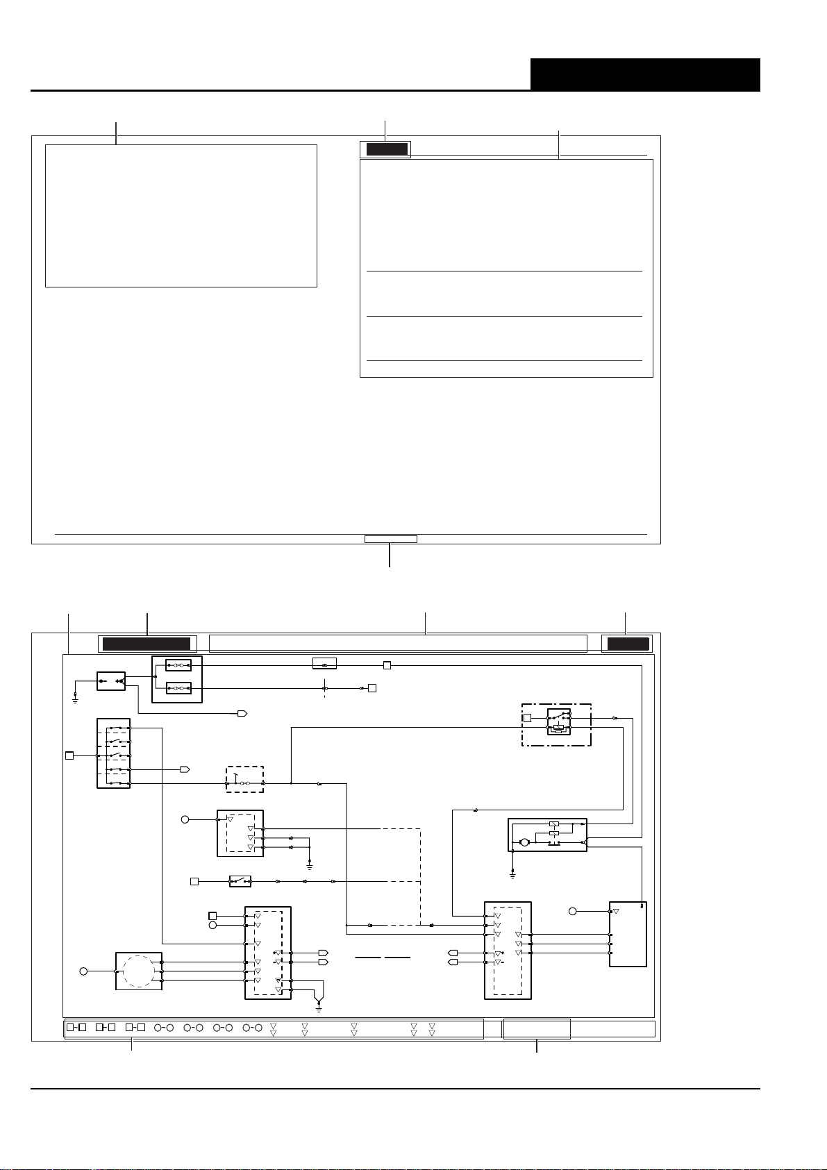
Figure and Data Page Layout
Figure Pages
Each Figure represents a specific electrical system of the vehicle. The Figures are arranged numerically by system (01 – Power
Distribution, 02 – Battery; Starter; Generator, etc.) with variations in the system identified by a numeral following a decimal point
(01.1, 01.2, etc.). Refer to the Table of Contents : Figu res for a complete list of the Figures.
The Figures 01 – Power Distribution detail the distribution of power to each of the systems. Numbered reference symbols refer the
user to a specific Figure and from a specific Figure back to the Power Distribution Figures. This method eliminates the need to
include detailed Power Distribution information on each of the Figures. The reference symbols are defined on page 9.
Each Figure appears on a right-hand page with a corresponding Data page to the left. The Figure and Data pages are folding pages.
The user must fold out both pages in order to access all the information provided.
Data Pages
The Data page includes information to assist the user in identifying and locating components, connectors and grounds.
This information is supplemented by the illustrations in this front section of the book.
Most circuits that incorporate a control module include pin-out information. The characteristics listed are approximately those that
can be expected at the control module connector pins with all circuit connections made and all components connected and fitted.
This information is provided to assist the user in understanding circuit operation and should be used FOR REFERENCE ONLY.
DATE OF ISSUE: January 2007 7
Page 12
User Instructions X-TYPE - VIN: E19616 on
CONTROL MODULE PIN OUT INFORMATION
Engine Control Module
Pin Description and Characteristic
I PI1–6 ENGINE CRANK: B+
I PI1–31 AUTOMATIC–PARK / NEUTRAL SIGNAL:B+ WHEN ACTIVATED
MANUAL,ROW – PARK /NE UTRALSIGNAL: B+ WHEN IGNITION CRANK(III)
MANUAL,NAS – CLUTCH PEDALSAFETY SWITCH (PARK / NEUTRALSIGNAL) : B+ WHEN ACTIVATED
O PI1–41 STARTERRELAY DRIVE:TO ACTIVATE, ECM SWITCHES CIRCUITTO GROUND
O PI1–53 FUELPUMP 2DRIVE (TO FUEL PUMP 2MODULE): PWM, 150 Hz, NORMALP OSITIVEDUTY CYCLE RANGE = 4%– 51%
I PI1–65 GENERATOR FIELD RETURN SIGNAL: VARIABLEVOLTAGE BY GENERATOR OPERATING CONDITION
I PI1–79 GENERATOR FAULT; CHARGE WARNING
C PI1–123 CAN –
C PI1–124 CAN +
Instrument Cluster
Pin Description and Characteristic
I FC14–2 KEY-IN AUDIBLE WARNING: B+ WHENKEY IN
B+ FC14–3 IGNITION SWITCHED POWER SUPPLY (II):B+
SG FC14–14 SIGNAL GROUND:GROUND
PG FC15–2 POWER GROUND: GROUND
B+ FC15–3 BAT TERYPOWER SUPPLY (LOGIC): B+
I FC15–4 PATS GROUND: GROUND
D FC15–5 PATS TRANSCEIVER:ENCODED COMMUNICATION
D FC15–6 PATS TRANSCEIVER:ENCODED COMMUNICATION
C FC15–18 CAN+
C FC15–19 CAN–
Transmission Control Module
Pin Description and Characteristic
B+ GB2–9 IGNITIONSWITCHEDPOWER SUPPLY: B+
O GB2–10 PARK / NEUTRAL SIGNAL: GROUNDWHEN ACTIVATED
PG GB2–13 POWER GROUND: GROUND
PG GB2–16 POWER GROUND: GROUND
The following abbreviations are used to represent values for Control Module Pin-Out data
I Input
O Output
B+ Battery Voltage
CAUTION: The information on this data page is furhished to aid the user in understanding circuit operation. THIS INFORMATION SHOULD BE USED FOR
REFERENCE ONLY.
NOTE: The values listed are appr oximately those that can be expected atthe control module connector pins with all ciruitconnections made and all
components connected and fitted.
PG PowerGround
SS Sensor / Signal Supply V
SG Sensor/ Signal Ground
C CAN Network
S SCP Network
D2 D2B Network
D Serial and Encoded Data
V Voltage (DC)
PWM Pulse Width Modulated
FIGURE NUMBER
COMPONENT, CONNECTOR AND GROUND
INFORMATION
Fig. 02.1
COMPONENTS
Component Connector(s) Connector Description Location
BATTERY — — LUGGAGE COMPARTMENT
CLUTCHPEDAL SAFETY SWITCH CA286 2-WAY / BLACK TOPOF CLUTCH PEDAL (BOTTOMSWITCH)
ENGINECONTROL MODULE PI1 134-WAY/ BLACK FRONT BULKHEAD,PASSENGER SIDE
FRONTPOWER DISTRIBUTION FUSE BOX — — ENGINE COMPARTMENT, RH SIDE
GENERATOR(V6) PI47 4-WAY / BLACK ENGINE, RHSIDE, FRONT
IGNITIONSWITCH FC18 7-WAY/BLACK STEERING COLUMN COWLING
INSTRUMENTCLUSTER FC14 22-WAY/GREY INSTRUMENT PANEL
PASSIVEANTI-THEFT SYSTEM TRANSCEIVER FC52 4-WAY/ GREEN STEERING COLUMN, IGNITION SWITCH
PRIMARYJUNCTION FUSEBOX CA2 26-WAY / BLACK RH‘A’ POST
STARTERMEGAFUSE — — LUGGAGE COMPARTMENT
STARTERMOTOR — — ENGINE BLOCK, RH SIDE
STARTERRELAY — — FRONT POWER DISTRIBUTION FUSE BOX– R20
TRANSMISSIONCONTROL MODULE GB2 16-WAY / BLACK TRANSMISSION CONTROLVALVE ASSEMBLY
HARNESS IN-LINE CONNECTORS
Connector Connector Description / Location Location
FH3 16-WAY/ BLUE / CABINHARNESS TO FRONT HARNESS LH ‘A’ POST
GB1 16-WAY/ GREY /ENGINE HARNESS TO TRANSMISSION HARNESS ADJACENTTO TRANSMISSION BELL HOUSING
PI41 42-WAY/ BLACK/ ENGINE HARNESS TO VEHICLEHARNE SSES ENGINECOMPARTMENT, BULKHEAD, PASSENGER SIDE
PI42 8-WAY/ BLACK/ ENGINE HARNESS TO FRONTHARNESS ENGINECOMPARTMENT, BULKHEAD, PASSENGER SIDE
ST4 2-WAY/ GREY / FRONT HARNESSTO STARTER LINK ENGINECOMPARTMENT, REARWARD OF RHWHEE LARCH
GROUNDS
Ground Location
FC38 UNDER CENTER OF INSTRUMENTPANEL, ON TRANSMISSION TUNNEL
JB1 LUGGAGE COMPARTMENT,BATTERY GROUND
PI40(LHD) ENGINECOMPARTMENT, BEHINDRH WHEEL ARCH LINER
PI40(RHD) ENGINECOMPARTMENT, BEHIND LH WHEEL ARCHLINER
ST2 ENGINECOMPA RTMENT,BEHIND LH WHEEL ARCH LINER
FOR CONTROL MODULE PIN-OUT INFORMATION, UNFOL D PAGE TO LEFT.
Refer to the front of this book for detailed information and illustrations regardingthe location andidentification o f harnesses, relays, fuses, grounds,
control modules and control modu le pins.
DATEOF ISSUE: February 2004
ST7 EYELET
FC15 20-WAY/ BLACK
FC63 22-WAY/ BLACK
CA56 8-WAY/BLACK
FC37 26-WAY/ BLACK
FH7 6-W AY/ BLACK
FH53 10-WAY/ BLACK
DATA PAGE
FIGURE
MODEL RANGE AND YEAR
R
CA280 CA304
B
CA288
BATTERY
JB1
KEY-IN
WU
FC18-5
0
NR
7
13 4
Fig.01.1
I
FC18-4
II
III
IGNITION SWITCH
NG
56
S
FC52-1
PASSIVE ANTI-THEFT SYSTEM TRANSCEIVER
76 77 92
Fig.01.2
WG
FC18-7
WB
FC18-1
Fig.01.3
450A
STARTER MEGAFUSE
250A
FPDB MEGAFUSE
MEGAFUSE ASSEMBLY
01.5
FC52-3
FC52-4
FC52-2
114
ll
Fig.01.4
Battery; Starter; Generator: V6
R
CA302
R
CA135
REARPOWER DISTRIBUTION
R
01.1
FUSEBOX
IGNITIONSWITCHED
CIRCUITS(II)
FC37-3 FH53-3
PRIMARY JUNCTION FUSE BOX
GO
18
II
B
+
GB2-9
TRANSMISSION CONTROL MODULE
NR GR GR GR GR
92
CA286-1 CA286-2
CLUTCH PEDAL SAFETY SWITCH
NG
85
WG
35
II
WU
WR
YR
BG
15 45
46 80
ll ll
SS
Fig.01.6
Fig.01.5
FC8-15
FC8-14
FC8-5
FC9-32
FC9-16
FC9-31
F15A
P,N
81 118
EE
O
GB2-10
P
GB2-13
P
GB2-16
B
LOGIC
+
B
+
PASSIVE
ANTI-THEFT
SYSTEM
I
D
D
P
INSTRUMENT CLUSTER
Fig.01.7
YYY
FHS63
GR
BB
GB1-10
BB
PIS30
GB1-9
PI42-8 GB1-13
FH3-10
Y
C
FC9-28
G
C
FC9-29
B
FC8-32
B
P
FC8-2
B
I
Input
+
O
P
Output
ST11 ST12
JUNCTION BLOCK
FH83CA177
FRONT BULKHEAD
PI41-34
B
PI40AL
20.1
O.K.TO START
20.1
FC38
Battery Voltage
PowerGround
DATE OF ISSUE
FH67
Y
YY
PIS27
GB1-14
+
Sensor/Signal Supply V
–
Sensor/Signal Ground
TITLE FIGURE NUMBER
Battery; Starter; Generator: V6
R
3
2
R20
NW
65
STARTER RELAY
FRONT POWER DISTRIBUTION FUSE BOX
PI41-40
(AUTO)
ST3
STARTER MOTOR
B
GO
PI1-41
GR
PI1-31
Y
PI1-6
Y
PI1-124
G
PI1-123
ST2
START
O
ENGINE
I
P,N
CRANK
II
ENGINE
REQUEST
O
I
C
C
ENGINE CONTROL MODULE
VARIANT: V6Vehicles
VINRA NGE: All
DATEOF ISSUE: February 2004
20
PI1-65
PI1-53
PI1-79
(MAN / NAS)
(MAN / ROW)
GB1-6
GENERATOR WARNING;
CLUTCHDISENGAGED
C
CAN
S
SCP
20.1
20.1
D
D2B Network
2
D
Serial and Encoded Data
Fig. 02.1
GW
ST4-1
GO
GW
ST5
R
R
ST6
GO
B
II
+
PI47-2
WR
FIELD
PI47-3
YR
CONTROL
PI47-1
WG
FAULT;
PI47-4
CHARGEWARNING
GENERATOR
FIGURE PAGE
ST7
f02_1_200045
KEY TO REFERENCE SYMBOLS
VARIANT, VIN RANGE AND DATE OF ISSUE
8 DATE OF ISSUE: January 2007
Page 13
Symbols and Codes
Symbols and CodesX-TYPE - VIN: E19616 on
NOTE: In the examples on this page, an ‘X’ is used where a number would appear on an actual Figure.
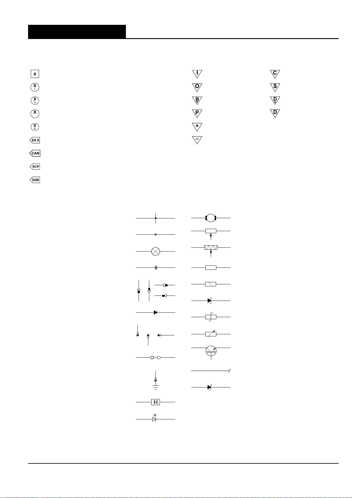
Reference Symbols Control Module Pin Symbols
Battery power supply
Ignition switched auxiliary power supply (key I)
Ignition switched power supply (key II, III)
Ignition switched Battery Saver power supply
B
Engine Management System power supply
Figure number reference
Controller Area Network
Standard Corporate Protocol network
D2B network
Wiring Symbols
Splice
Simplified splice
Input CAN network
Output SCP network
Battery voltage D2B network
Power ground Serial and encoded data
Sensor / signal supply V *
Sensor / signal ground **
* May also indicate Reference Voltage.
** May also indicate Reference Ground or Logic Ground.
Refer to Control Module Pin-out Information.
Motor
Potentiometer
Bulb
Capacitor
Connector
Diode
Eyelet and stud
Fuse
Ground
Hall effect sensor
Light emitting diode (LED)
Pressure transducer
Resistor
Solenoid
Suppression diode
Suppression resistor
Thermistor
Transistor
Wire continued
Zener diode
DATE OF ISSUE: January 2007 9
Page 14

Symbols and Codes X-TYPE - VIN: E19616 on
Harness Codes Wiring Color Codes
AC Climate Control
AS Side Airbag
BH Engine Block Heaters
BL LH Rear Door
BR RH Rear Door
CA Cabin
DE Diesel Engine
DL Diesel Engine Link
EN Engine
FB Front Bumper
FL LH Front Door
FR RH Front Door
FT Fuel Tank
GC Cooling Pack
IJ Injector Rail
IP Instrument Panel
JB Junction Box
LF LH Front Wheel Speed Sensor
LR LH Rear Wheel Speed Sensor
LS LH Front Seat
NA Navigation System
PA Pedal Assembly
PH Telephone
RB Rear Bumper
RC Roof Console
RF RH Front Wheel Speed Sensor
RR RH Rear Wheel Speed Sensor
RS RH Front Seat
SL Security Sounder Link
TL Trunk Lid
TT Trailer Towing
TV Television
WG Tailgate Glass (Estate / Wagon only)
WL Tailgate Link (Estate / Wagon only)
WS Weight Sensor
WT Tailgate (Estate / Wagon only)
N Brown O Orange
BBlack S Slate
W White L Light
KPink U Blue
G Green P Purple
RRed BRDBraid
Y Yellow BOF Fiber optic (D2B Network)
Code Numbering
When numbering connectors, grounds and splices, Jaguar
Engineering uses a three-position format: AC001, AC002, etc.
Because space is limited in this Electrical Guide the codes
have, in most cases, been shortened. Thus AC001–001
becomes AC1–1, AC002–001 becomes AC2–1, etc.
10 DATE OF ISSUE: January 2007
Page 15
Symbols and CodesX-TYPE - VIN: E19616 on
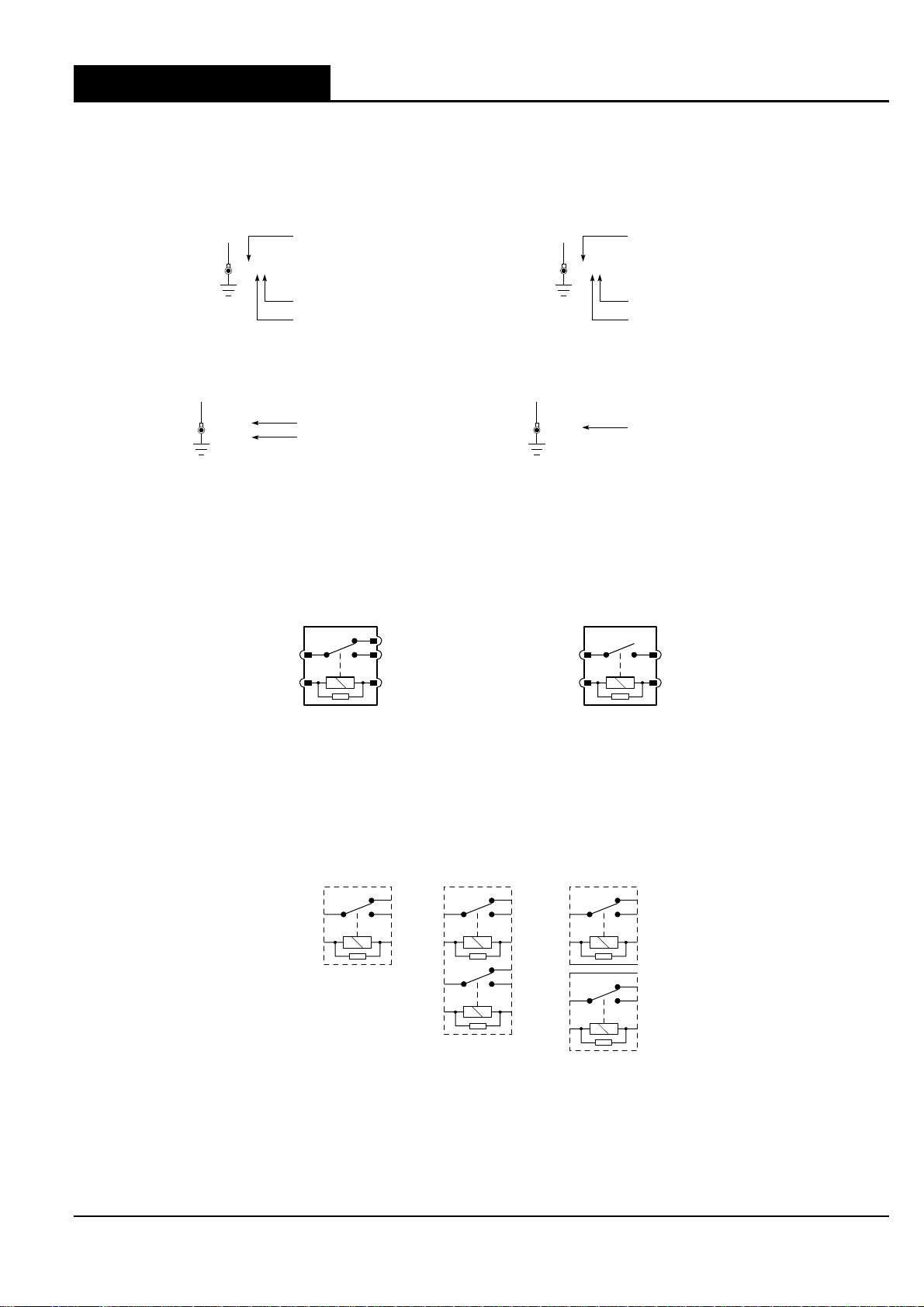
Grounds
• There may be up to three eyelets on one ground stud.
• A, B and C are used to indicate the position of the eyelet on the stud: A – first (bottom), B – second (middle), C – third (top).
• Two eyelet variations are used: a single eyelet and an eyelet pair. The single eyelet has a single ‘leg’, which is identified by
an S; the eyelet pair has two ‘legs’, identified as L (left) or R (right).
EXAMPLE:
G30A
Ground stud number 30
G17BR
Single eyelet
First eyelet on stud
Ground stud number 17
Eyelet pair, RH leg
Second eyelet on stud
On figures where LHD and RHD circuits are combined and the ground designation differs from LHD to RHD, the RHD ground is
shown in parentheses. If the ground designation is the same for LHD and RHD, only one ground designation is used.
EXAMPLE:
G30AS
(G26AS)
LHD Vehicles
RHD Vehicles
G31BL
Same for LHD and RHD Vehicles
Relays
Serviceable Relays:
• are located in both fuseboxes;
• do not have a separate relay connector (base);
• use the ISO pin numbering system – 1, 2, 3, 4, 5;
• are identified by an ‘R’ number unique only to the fusebox in which it is located.
EXAMPLE:
3
1
4
R6
5
2
R2
3
1
5
2
CHANGE-OVER RELAY NORMALLY OPEN RELAY
Non-Serviceable Relays:
• are located in both fuseboxes;
• are a component part of the fusebox printed circuit board (PCB) and are arranged in singles or pairs;
• use the ISO pin numbering system – 1, 2, 3, 4, 5 (single relay or top pair relay) and 6, 7, 8, 9, 10 (bottom pair relay);
• are identified by an ‘R’ number unique only to the fusebox in which it is located;
• pair relays are normally depicted separately.
EXAMPLE:
R10
3
1
SINGLE
PCB RELAY
4
5
2
R9
3
1
8
6
PCB
PAIR RELAY
4
5
2
9
10
7
R9
3
1
R9
8
6
PCB
PAIR RELAY
AS DEPICTED
4
5
2
9
10
7
NOTE: Diesel vehicles have one serviceable relay located on the Junction Box harness and one serviceable relay attached to the
Power Distribution Fusebox.
DATE OF ISSUE: January 2007 11
Page 16
Symbols and Codes X-TYPE - VIN: E19616 on
Fuses
All fuses are located in the fuseboxes. Each fuse is identified by an ‘F’ number unique only to the fusebox in which it is located.
EXAMPLE:
F19 15A
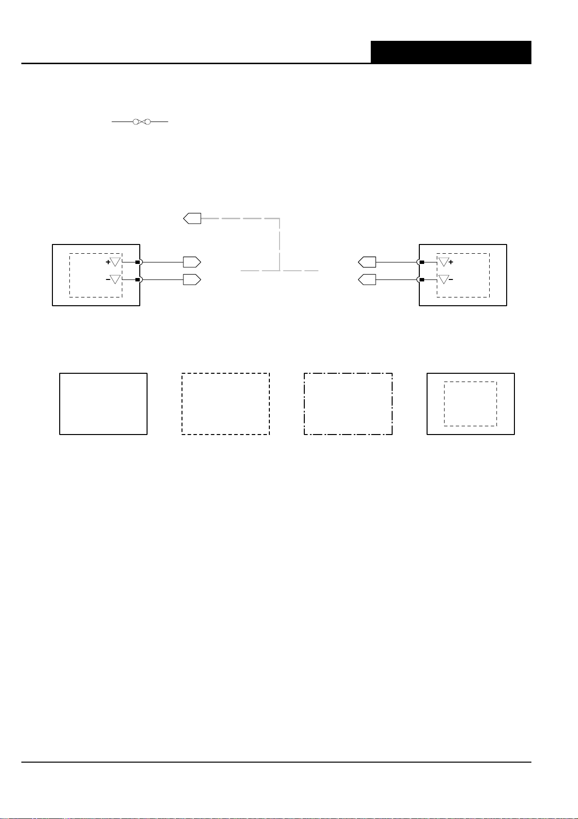
Networks
In most instances, networks are shown as a broken grey line to indicate that there is network communication between the depicted
control modules. Refer to Figures 20.1, 20.2, 20.3 and 20.4 for circuit details.
EXAMPLE:
SCP
S
S
CONTROL MODULE CONTROL MODULE
Component Depictions
EXAMPLE:
COMPLETE COMPONENTS
AND CONTROL MODULES
IP5-1
IP5-2
Y
20.2
MESSAGE(S) MESSAGE(S)
U
20.2 20.2
INCOMPLETE COMPONENTS
(EXCEPT CONTROL MODULES)
MESSAGE(S)MESSAGE(S)
ASSEMBLIES AND
POWER DISTRIBUTION FUSE BOXES
20.2
Y
U
IP10-1
IP10-2
S
S
COMPONENTS WITH
INTERNAL ELECTRONIC CIRCUIT
12 DATE OF ISSUE: January 2007
Page 17
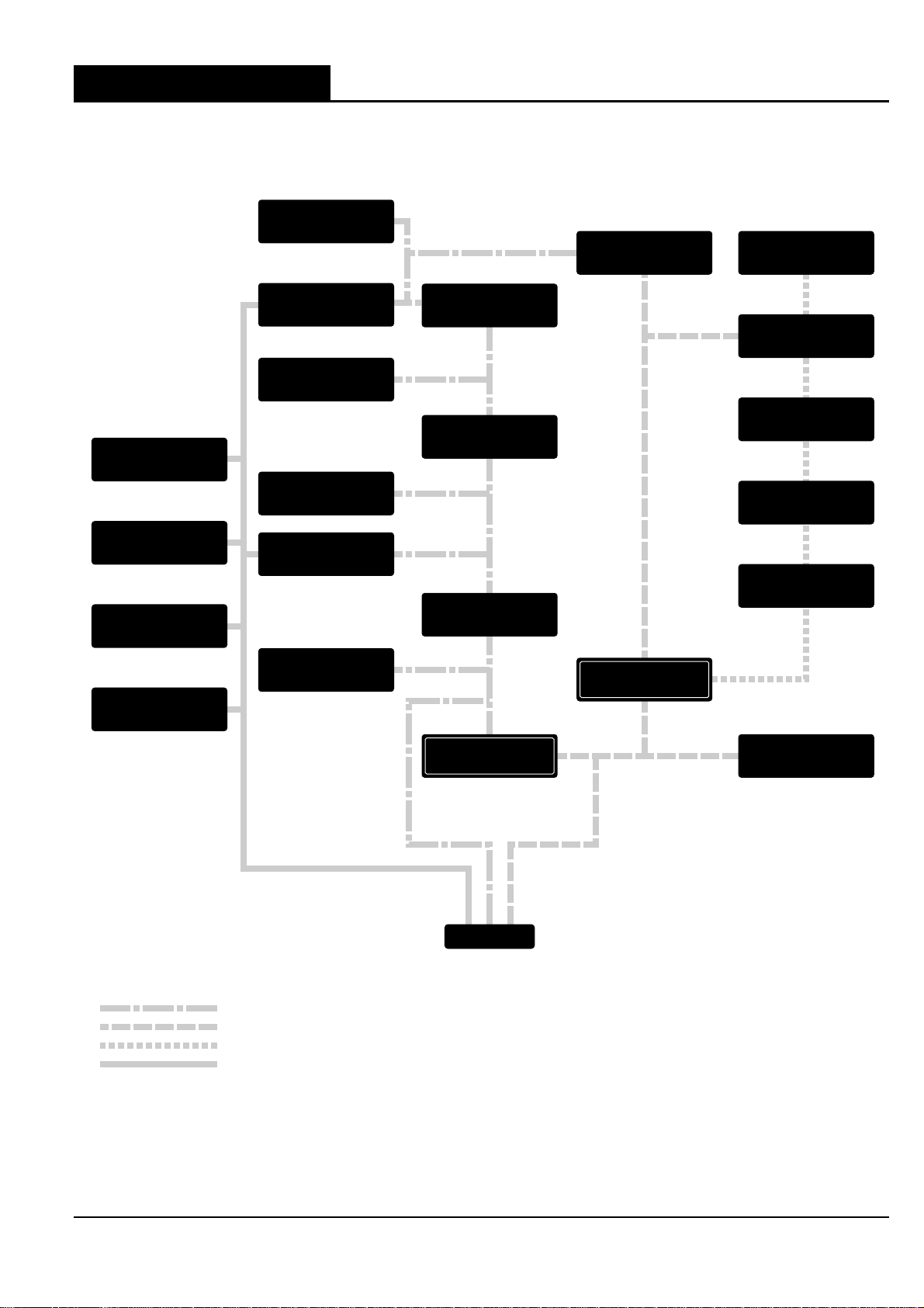
Network Configuration
ABS, ABS/TC OR DSC
CONTROL MODULE
Network ConfigurationX-TYPE - VIN: E19616 on
ENGINE
CONTROL MODULE
(DIESEL ENGINES)
POWER
AMPLIFIER
RESTRAINTS
CONTROL MODULE
PARKING AID
MODULE
ROOF
CONSOLE
FUEL FIRE
AUXILIARY HEATER
MODULE
ENGINE
CONTROL MODULE
(GASOLINE ENGINES)
DRIVER SEAT
MODULE
DSC
YAW RATE SENSOR
HEADLAMP LEVELING
MODULE
DSC
STEERING ANGLE
SENSOR
TRANSMISSION
CONTROL MODULE
CLIMATE
CONTROL MODULE
J-GATE MODULE
INSTRUMENT
CLUSTER
NETWORK GATEWAY
AUDIO UNIT
NETWORK GATEWAY
NAVIGATION
MODULE
VOICE ACTIVATION
MODULE
CELLULAR PHONE
MODULE
CD
AUTOCHANGER
D2B
GENERAL ELECTRONIC
MODULE
CAN
SCP
SERIAL DATA LINK
DATA LINK CONNECTOR
CAN NETWORK
SCP NETWORK
D2B NETWORK
SERIAL DATA LINK
NOTE: TYPICAL NETWORK CONFIGURATION.
REFER TO FIGURES 20.1, 20.2, 20.3 AND 20.4 FOR CIRCUIT DETAILS.
net_con_4000625
DATE OF ISSUE: January 2007 13
Page 18
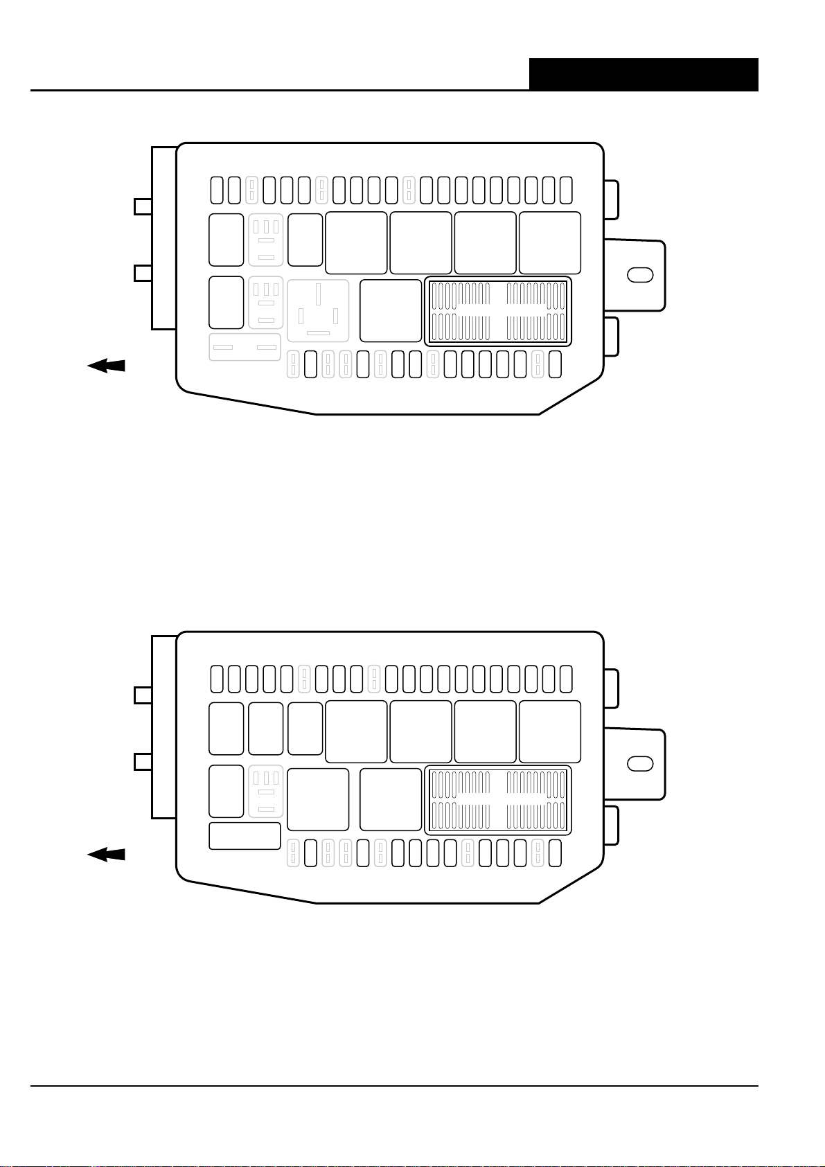
Relay and Fuse Location
Relay and Fuse Location X-TYPE - VIN: E19616 on
POWER DISTRIBUTION FUSE BOX (TOP): GASOLINE ENGINE VEHICLES
FRONT OF VEHICLE
F1
10AF215AF410AF510AF67.5AF830AF930A
R1 R3
R8
F24
30A
F10
F11
15A
15A
R4 R5 R6 R7
R11
F27
F29
15A
20A
R1 MAIN BEAM / FRONT FOG RELAY
R2 NOT USED
R3 A/C COMPRESSOR CLUTCH RELAY
R4 WINDSHIELD WIPER MOTOR RELAY
R5 POWER DISTRIBUTION FUSE BOX IGNITION RELAY
R6 WINDSHIELD HEATER RELAY
R7 EMS CONTROL RELAY
R8 POWERWASH PUMP RELAY
F30
20A
F135AF14
30A
F32
15A
F15
F165AF17
F18
F19
30A
10A
10A
10A
F20
30A
R12, R13, R14, R10*
F35
F34
30A
F365AF38
5A
20A
F33
30A
R9 NOT USED
R10 NOT USED
R11 DIP BEAM RELAY
R12 STARTER RELAY
R13 SLAVE IGNITION RELAY
R14 NOT USED
R15 HORN RELAY
F21
30A
* NON-SERVICEABLE PCB RELAYS
FRONT OF VEHICLE
POWER DISTRIBUTION FUSE BOX (TOP): DIESEL ENGINE VEHICLES
F1
10AF215AF320AF410AF510AF75AF830AF930A
R1 R2 R3
R8
F22
60A
F24
30A
R1 MAIN BEAM / FRONT FOG RELAY
R2 HORN RELAY
R3 A/C COMPRESSOR CLUTCH RELAY
R4 WINDSHIELD WIPER MOTOR RELAY
R5 POWER DISTRIBUTION FUSE BOX IGNITION RELAY
R6 WINDSHIELD HEATER RELAY
R7 EMS CONTROL RELAY
R8 POWERWASH PUMP RELAY
F11
F12
F135AF14
F15
F165AF17
F18
F19
15A
7.5A
30A
30A
10A
10A
10A
F20
7.5A
R4 R5 R6 R7
F27
15A
R11R10
F29
F30
20A
20A
R12, R13, R14, R10*
F31
F32
15A
15A
F34
30A
F35
F36
5A
7.5A
R9 NOT USED
R10 GLOW PLUG RELAY
R11 DIP BEAM RELAY
R12 STARTER RELAY
R13 SLAVE IGNITION RELAY
R14 NOT USED
R15 AUXILIARY HEATER RELAY 1
F21
15A
F38
30A
* NON-SERVICEABLE PCB RELAYS
pw_dis_fuse_box_4000625
14 DATE OF ISSUE: January 2007
Page 19
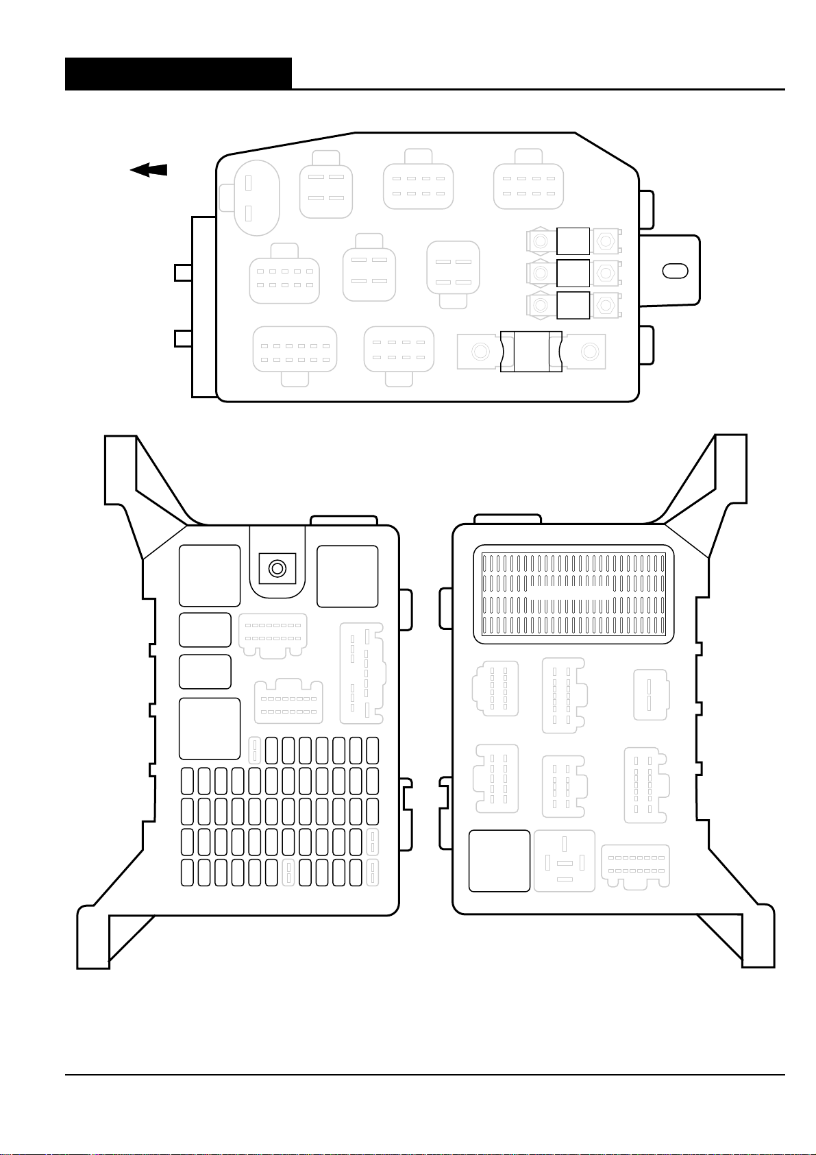
FRONT OF VEHICLE
Relay and Fuse LocationX-TYPE - VIN: E19616 on
POWER DISTRIBUTION FUSE BOX (BOTTOM)
F39
150A
F42
50A
F41
60A
F40
80A
PASSENGER JUNCTION
FUSE BOX (FRONT)
R4
R3
R2
R1
F55
F545AF53
F52
10A
15A
F42
F41
F40
5A
5A
F30
F29
F28
5A
7.5A
15A
F18
F17
F16
15A
20A
30A
F5
20A
20A
7.5A
20A
20A
10A
F48
F36
F24
F12
F47
7.5A
F35
15A
F23
20A
F11
20A
7.5A
F46
F34
10A
F22
15A
F10
15A
7.5A
F45
F44
F43
10A
15A
10A
F32
F31
F33
5A
15A
5A
F21
F20
F19
20A
30A
30A
F9
F8
F7
10A
20A
10A
PASSENGER JUNCTION
FUSE BOX (BACK)
R5
R7, R8, R9, R10*
F51
F505AF49
7.5A
10A
F39
F38
10A
F27
F15
10A
30A
F37
15A
30A
F26
F25
5A
10A
5A
F14
30A
F3
F2
10A
R6
5A
F4
* NON-SERVICEABLE PCB RELAYS
R1 FOLD-BACK MIRROR MODULE
R2 ACCESSORY RELAY
R3 REAR WIPER MOTOR RELAY(ESTATE / WAGON ONLY)
R4 BLOWER MOTOR RELAY
R5 PASSENGER JUNCTION FUSE BOX IGNITION RELAY
R6 HEATED REAR WINDOW RELAY
R7 THROTTLE MOTOR RELAY (2.5 L, 3.0 L)
FUEL PUMP RELAY (2.0 L)
R8 NOT USED
R9 REVERSE LAMPS RELAY
R10 BATTERY SAVER RELAY
pw_dis_fuse_bot_4000625
DATE OF ISSUE: January 2007 15
Page 20
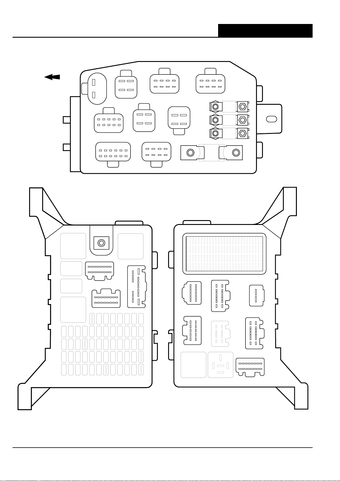
Fusebox Connectors
Fusebox Connectors X-TYPE - VIN: E19616 on
POWER DISTRIBUTION FUSE BOX (BOTTOM)
FRONT OF VEHICLE
JB208
1
2
4
3
5
10
JB209
2
1
JB205
1
6
JB202
12 7
6
1
PASSENGER JUNCTION
FUSE BOX (FRONT)
JB204
1
3
JB207 JB206
1
5
4
88
JB203
2
4
4
3
2
1
JB201
8
4
5
1
JB200
PASSENGER JUNCTION
1
5
4
JB211
JB210
JB212
FUSE BOX (BACK)
IP203
916
8
1
IP202
IP201
1
8
CA209
6
81
13
169
7
1
CA206
5
1
CA208
12
7
8
14 7
1
JB221
1
2
JB220
10
6
1
8
7
14
CA204
916
8
1
fuse_box_con_4000625
16 DATE OF ISSUE: January 2007
Page 21
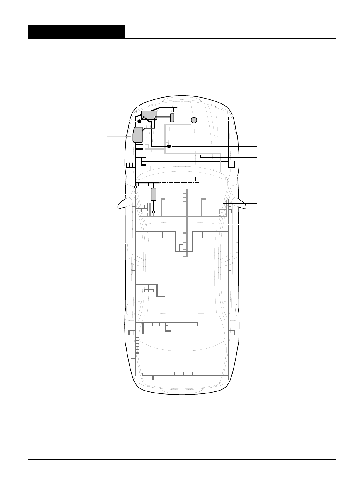
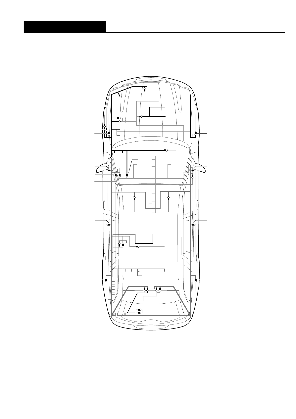
Major Harnesses and Fusebox Location
BATTERY
BATTERY CHASSIS GROUND
(UNDER BATTERY TRAY)
Major Harnesses and Fusebox LocationX-TYPE - VIN: E19616 on
SEDAN (GASOLINE ENGINE SHOWN)
+
-
STARTER MOTOR
GENERATOR
POWER DISTRIBUTION
FUSE BOX
JUNCTION BOX HARNESS (JB)
PASSENGER JUNCTION
FUSE BOX
CABIN HARNESS (CA)
-
BATTERY ENGINE GROUND
ENGINE HARNESS (EN)
RHD JUNCTION BOX
HARNESS DEVIATION
RHD INSTRUMENT PANEL
HARNESS DEVIATION
INSTRUMENT PANEL HARNESS (IP)
harn_fuse_box.loc_4000625
DATE OF ISSUE: January 2007 17
Page 22
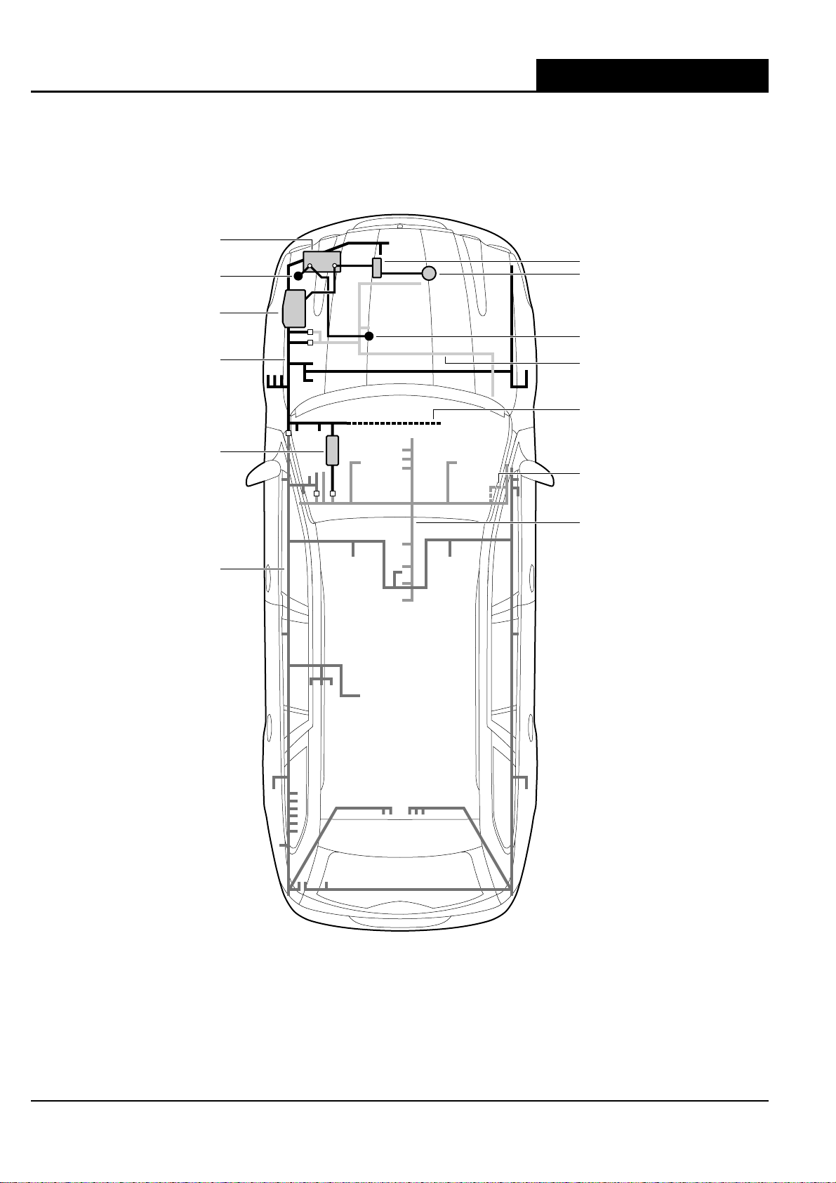
Major Harnesses and Fusebox Location X-TYPE - VIN: E19616 on
ESTATE / WAGON (GASOLINE ENGINE SHOWN)
BATTERY
+
BATTERY CHASSIS GROUND
(UNDER BATTERY TRAY)
-
-
STARTER MOTOR
GENERATOR
POWER DISTRIBUTION
FUSE BOX
JUNCTION BOX HARNESS (JB)
PASSENGER JUNCTION
FUSE BOX
CABIN HARNESS (CA)
-
BATTERY ENGINE GROUND
ENGINE HARNESS (EN)
RHD JUNCTION BOX
HARNESS DEVIATION
RHD INSTRUMENT PANEL
HARNESS DEVIATION
INSTRUMENT PANEL HARNESS (IP)
est_fuse_box_loc_4000625
18 DATE OF ISSUE: January 2007
Page 23
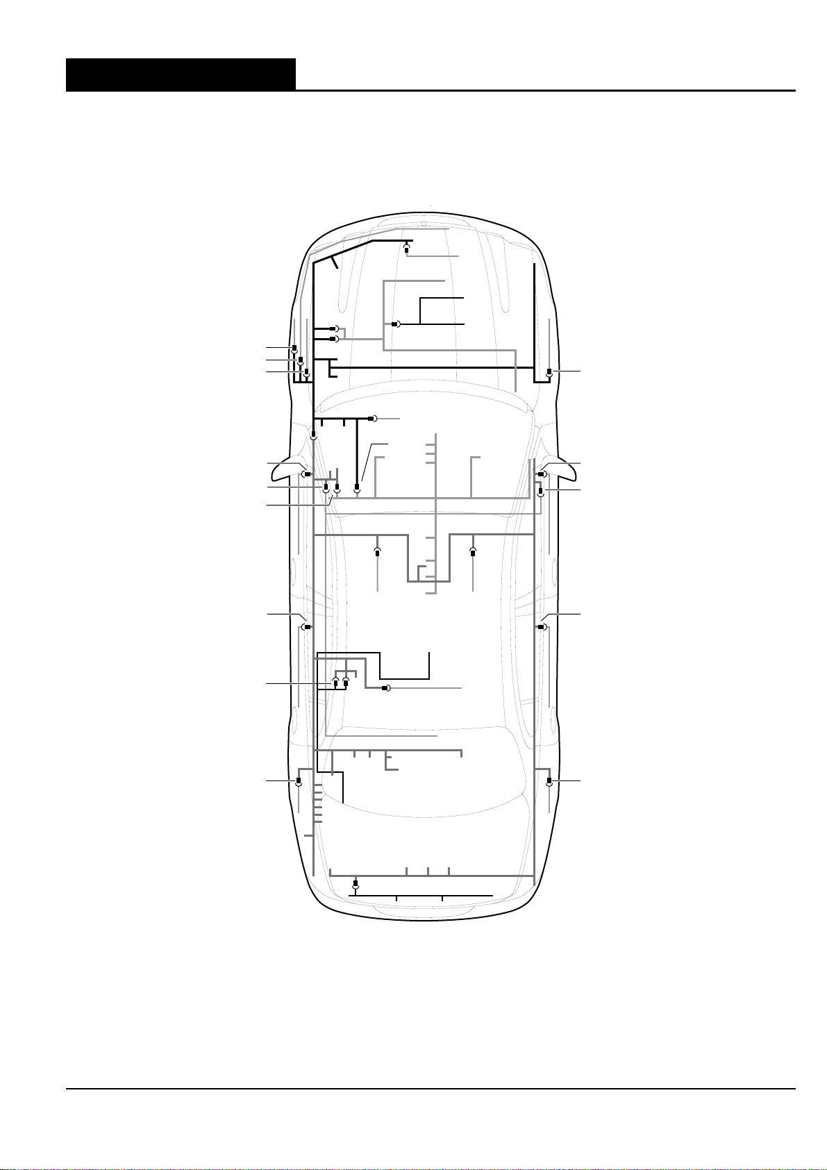
Harness In-Line Connector Location
Harness In-Line Connector LocationX-TYPE - VIN: E19616 on
SEDAN: GASOLINE ENGINE (LHD SHOWN)
JB187
JB188
JB79
JB173
JB133
CA15
CA16
CA36
CA1
CA169
CA189
CA222
CA230
CA240
CA25
CA45
JB1
JB145
CA10
CA170
CA65
CA70
CA5
EN4
JB3
JB129
JB130
CA65
CA70
JB15
CA20
CA21
CA35
CA30
CA60
CA129
DATE OF ISSUE: January 2007 19
CA55
gas_harn_con_loc_4000625
Page 24
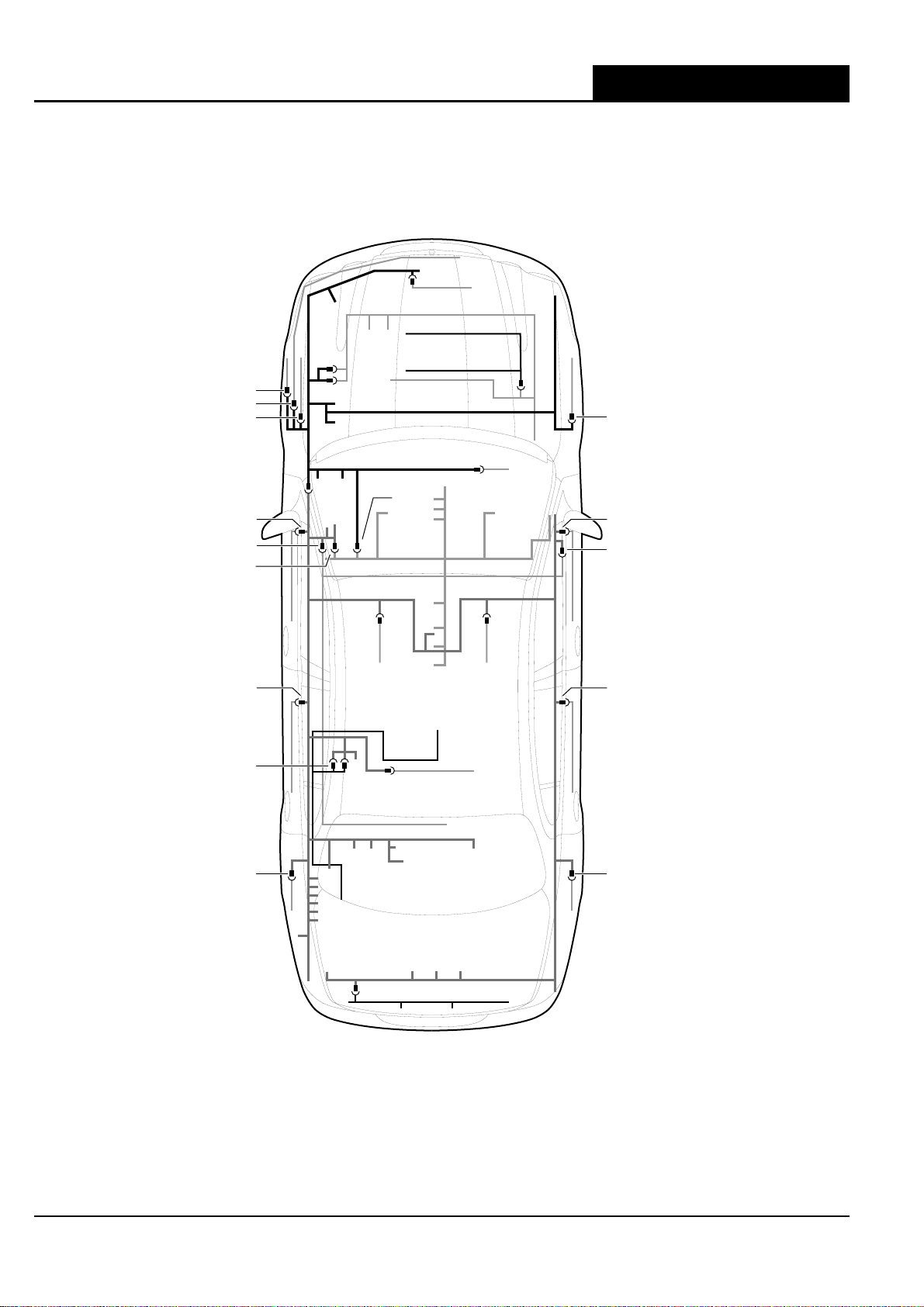
Harness In-Line Connector Location X-TYPE - VIN: E19616 on
SEDAN: DIESEL ENGINE (RHD SHOWN)
JB187
JB188
JB237
JB79
JB173
JB133
JB1
DL2
JB15
CA20
CA21
CA36
CA1
CA169
CA189
CA222
CA230
CA240
CA25
CA45
CA60
CA10
CA170
CA65
CA70
CA5
JB3
JB129
JB130
JB2
CA65
CA70
CA15
CA16
CA35
CA30
CA55
CA129
diesel_harn_con_loc_4000625
20 DATE OF ISSUE: January 2007
Page 25
Harness In-Line Connector LocationX-TYPE - VIN: E19616 on
ESTATE / WAGON (RHD SHOWN)
JB187
JB188
JB79
JB173
JB133
CA20
CA21
CA36
CA1
CA169
CA189
CA222
CA230
CA240
CA25
CA45
JB1
JB145
CA10
CA170
CA65
CA70
CA5
EN4
JB3
JB129
JB130
JB2
CA65
CA70
JB15
CA15
CA16
CA35
CA30
CA60
WL1
WT3
WT1
DATE OF ISSUE: January 2007 21
WL3
WG3
WG1
CA55
estate_harn_con_loc_400062
Page 26
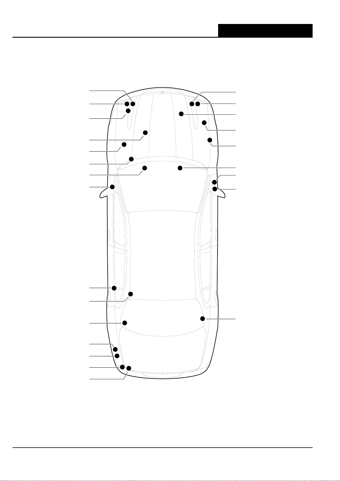
Ground Point Location
Ground Point Location X-TYPE - VIN: E19616 on
SEDAN SHOWN
LH HEADLAMP ASSEMBLY
G32 - UNDER
G11 - UNDERLH HEADLAMP
ASSEMBLY
G16 - UNDER BATTERY TRAY
(BATTERY CHASSIS GROUND)
G13 - ENGINE BLOCK
(BATTERY ENGINE GROUND)
G14 - REARWARD OF POWER
DISTRIBUTION FUSE BOX
G51 - UNDER BODY
LH DASH PANEL
G36 - LH CROSS CAR BEAM
G15 - LH 'A' POST, LOWER
G18 - UNDER
RH HEADLAMP ASSEMBLY
G10 - UNDER
RH HEADLAMP ASSEMBLY
G17 - ON GENERATOR BRACKET
G33-ABS/TC/DSC
CONTROL MODULE BRACKET
G8 - RH STRUT TOWER
G37 - RH CROSS CAR BEAM
G5 - RH 'A' POST, LOWER
G4 - RH 'A' POST, UPPER
G35 - LH 'E' POST, LOWER
G38 - ROOF, TOP OF LH 'E' POST
(HIGH MOUNT STOP LAMP GROUND -
(HEATED REAR WINDOW GROUND)
SEDAN ONLY)
G3 - LH 'E' POST
G39 - TRUNK, LH REAR
G40 - TRUNK, LH REAR
G2 - TRUNK, LH REAR
G1 - TRUNK, LH REAR
G50 - RH REAR ROOF PANEL
(ESTATE / WAGON ONLY)
NOTE: UNIQUE GROUND STUDS ARE NOTED IN PARENTHESES.
grd_pt_loc_4000625
22 DATE OF ISSUE: January 2007
Page 27
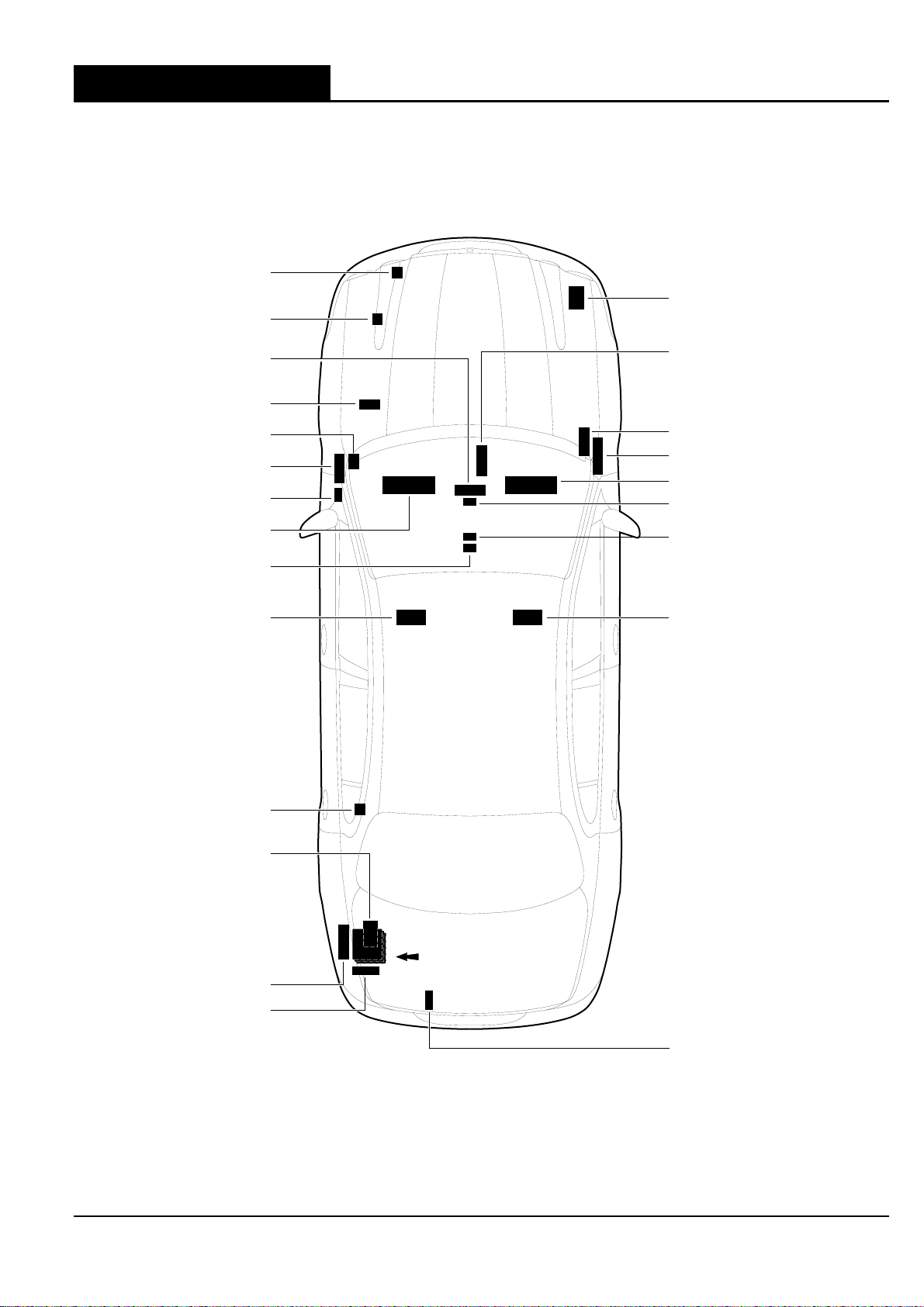
Control Module Location
COOLING FAN MODULE
VACUUM MODULE
CONTROL MODULE
(COMBINED WITH
CONTROL PANEL)
SPEED CONTROL
TRANSMISSION
CONTROL MODULE
HEADLAMP LEVELING
INSTRUMENT CLUSTER: LHD
CONTROL MODULE
CLIMATE
MODULE
RAIN SENSING
MODULE
MODULE
RESTRAINTS
Control Module LocationX-TYPE - VIN: E19616 on
SEDAN
ABS, ABS/TC OR
DSC MODULE
CLIMATE
CONTROL MODULE
(REMOTE)
ENGINE CONTROL MODULE
GENERAL ELECTRONIC
MODULE
INSTRUMENT CLUSTER: RHD
YAW RATE SENSOR
J GATE MODULE
DRIVER SEAT MODULE: LHD
FUEL PUMP MODULE
CONTROL MODULE STACK:
VOICE ACTIVATION
MODULE (TOP)
NAVIGATION
CONTROL MODULE
CD AUTOCHANGER
CELLULAR PHONE
MODULE (BOTTOM)
POWER AMPLIFIER
VEHICLE INFORMATION
CONTROL MODULE
DRIVER SEAT MODULE: RHD
FULL OPTION SET
SHOWN.
PARKING AID MODULE
cntrl_mod_loc_4000625
DATE OF ISSUE: January 2007 23
Page 28
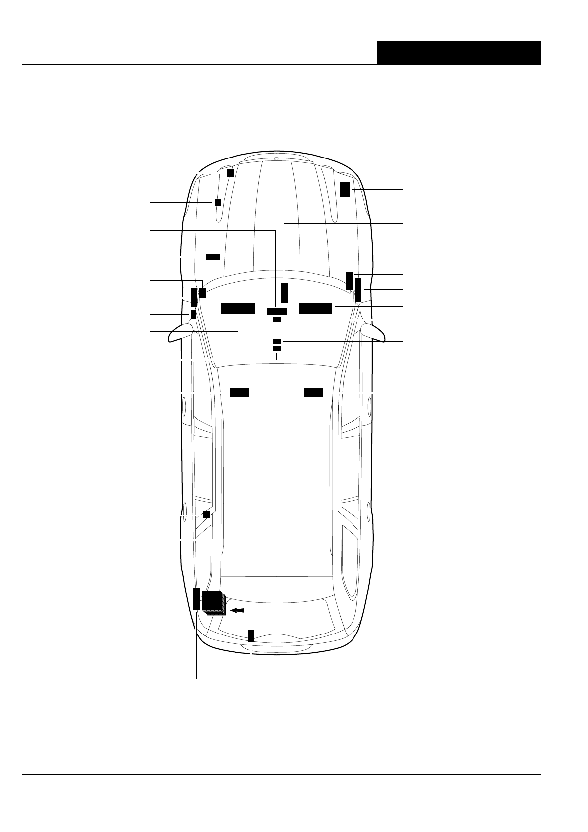
Control Module Location X-TYPE - VIN: E19616 on
5
ESTATE / WAGON
COOLING FAN MODULE
ABS, ABS/TC OR
VACUUM MODULE
CLIMATE
CONTROL MODULE
(COMBINED WITH
CONTROL PANEL)
SPEED CONTROL
MODULE
RAIN SENSING
MODULE
TRANSMISSION
CONTROL MODULE
HEADLAMP LEVELING
MODULE
INSTRUMENT CLUSTER: LHD
RESTRAINTS
CONTROL MODULE
DSC MODULE
CLIMATE
CONTROL MODULE
(REMOTE)
ENGINE CONTROL MODULE
GENERAL ELECTRONIC
MODULE
INSTRUMENT CLUSTER: RHD
YAW RATE SENSOR
J GATE MODULE
DRIVER SEAT MODULE: LHD
FUEL PUMP MODULE
CONTROL MODULE STACK:
VEHICLE INFORMATION
CONTROL MODULE (TOP)
NAVIGATION
CONTROL MODULE
CD AUTOCHANGER
VOICE ACTIVATION
MODULE
CELLULAR PHONE
MODULE (BOTTOM)
POWER AMPLIFIER
DRIVER SEAT MODULE: RHD
FULL OPTION SET
SHOWN.
TRAILER TOWING MODULE
estate_cnt_mod_loc_400062
24 DATE OF ISSUE: January 2007
Page 29
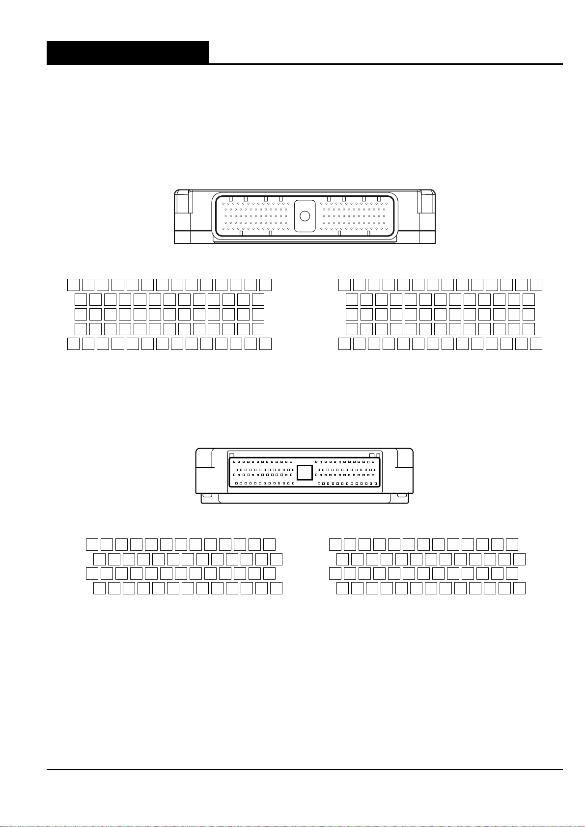
Control Module Pin Identification
ENGINE CONTROL MODULE - 2.5 L, 3.0 L
107Y108G109RW110G111B112-113BG114BO115BG116B117-118BO119BW120
81B82B83Y84G85-86-87GU88GW89GR90-91B92U93
55GO56GO57-58-59-60-61GU62GW63GR64-65OG66UY67
29B30B31B32-33WG34BG35-36G37Y38OY39OY40B41
1RU2RU3-4B5B6Y7GO8GO9U10GU11-12OY13Y14
EN16 / 134-WAY / BLACK
BW
UY
O
GO
-
Control Module Pin IdentificationX-TYPE - VIN: E19616 on
121WU122-123G124Y125-126-127BW128N129N130BR131YG132YG133BG134
94O95B96-97-98N99-100BG101-102R103Y104RG105W106
68G69N70UY71O72-73U74-75G76Y77-78Y79U80
42-43W44GW45BW46BW47YR48YG49-50U51WU52GR53RG54
15-16-17B18B19BG20BG21-22NR23WG24WG25W26-27N28
RW
R
G
B
-
ENGINE CONTROL MODULE - 2.0 L
79Y80UY81O82-83-84WG85B86G87N88G89Y90-91
53N54N55BR56GW57GU58-59O60B61G62Y63GO64B65
27N28-29BW30GW31BW32-33-34GO35U36GU37N38BG39
1BW2WU3BG4B5B6Y7U8OG9-10-11OY12YG13
EN65 / 104-WAY / BLACK
B
BG
W
YG
92BW93BW94BO95G96RW97G98R99GR100-101-102B103GO104
66BO67BG68GO69B70-71OY72-73-74UY75B76GO77RU78
40GU41GW42GR43RG44WU45-46UY47U48B49-50G51Y52
14GU15GW16GR17G18B19B20BG21NR22WG23WG24-25G26
RU
B
B
Y
cntrl_mod_pin_ld_4000625
DATE OF ISSUE: January 2007 25
Page 30
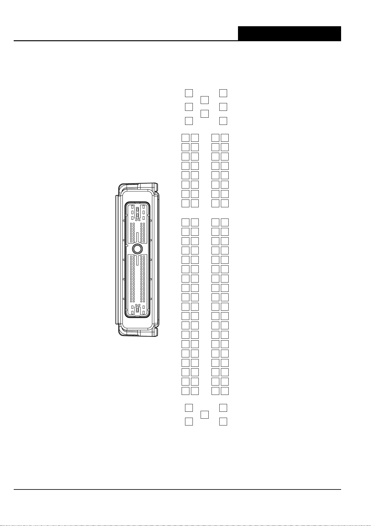
Control Module Pin Identification X-TYPE - VIN: E19616 on
ENGINE CONTROL MODULE - DIESEL
113
112
111
110
109
108
107
106
6
7
8
9
10
11
12
DL1 / 121-WAY / BLACK
13
15 14
16
17
18
19
20
21
22
23
24
121
120
119
-
N
-
NU
WU
YG
WG
WU
YG
YU
WU
B
-
-
BU
YG
NR
-
-
-
GU
-
OG
GO
-
-
-
GY
GW
-
116
BO
115
BW
114
-
-
97
89
-
B
96
88
95
87
BU
BU
94
86
BR
OY
-
93
85
NW
-
92
84
NU
-
91
83
WU
90
82
NR
WR
-
-
44
63
N
45
64
WK
-
46
65
NY
B
W
47
66
-
-
48
67
-
49
68
BG
-
50
69
WU
51
70
YU
NU
-
W
52
71
Y
N
53
72
Y
G
54
73
Y
U
55
74
-
-
56
75
-
57
76
YR
U
58
77
GO
-
-
59
78
-
60
79
BG
U
61
80
BO
-
62
81
BG
BU
118
BY
117
-
105
WU
104
NW
103
WK
102
NW
101
WK
NG
100
99
WG
-
98
25
WG
26
NG
27
NU
B
28
-
29
-
30
-
31
32
WR
33
YR
-
34
-
35
-
36
37
GO
38
BY
-
39
-
40
-
41
-
42
-
43
5
WG
3
4
WG
WG
2
B
1
B
2.0_cntrl_mod_pin_loc_4000625
26 DATE OF ISSUE: January 2007
Page 31

Control Module Pin IdentificationX-TYPE - VIN: E19616 on
TRANSMISSION CONTROL MODULE - 16 BIT
JB131 / 37-WAY / BLUE
18R17B16O15B14N13G12G11-10W9B8R7O6UY5O4U3G2-1
36WU35-34Y33Y32-31-30U29-28-27Y26S25W24N23-22-21G20R19
54WU53Y52G51-50-49-48-47OY46
BRD45BW44BRD43-42BRD41-40-39W38B37-
-
-
TRANSMISSION CONTROL MODULE - 32 BIT
JB230 JB231
JB230 / 24-WAY / WHITE JB231 / 24-WAY / GREY
1R2G3O4B5Y6G7W8Y9
10WU11B12N13-14Y15G16-17-18
19WU20G21
U
22-23
BRD24O
-
U
25B26
BRD27R28UY29O30-31-32-
34Y35S36W37-38N39G40-41OY42
43BW44
BRD45-
46-47W48
33
-
R
B
trans_cntrl_mod_4000625
DATE OF ISSUE: January 2007 27
Page 32

Control Module Pin Identification X-TYPE - VIN: E19616 on
ANTI-LOCK BRAKING SYSTEM MODULE OR
DYNAMIC STABILITY CONTROL MODULE
ANTI-LOCK BRAKING / TRACTION CONTROL MODULE
JB185 / 42-WAY / BLUE
1B2
11-12W13GB14WU15NR16WR17-18-19-20-21U22-23GW24Y25B26
27B28N29-30NG31WG32GO33-34-35-36-37-38-39GW40G41-42
R
3-4-5B6
R
7-8-9-10
-
WG
JB45 / 42-WAY BLUE (ABS)
1B2
11-12W13GB14WU15NR16WR17-18-19-20-21-22-23GW24Y25-26
27-28N29-30NG31WG32GO33-34-35-36-37-38-39-40G41-42
GB
R
3-4-5B6
R
7-8-9-10
-
-
-
JB197 / 42-WAY / BLUE (ABS/TC)
1B2
11-12W13GB14WU15NR16WR17-18-19-20-21-22-23GW24Y25-26
27B28N29Ñ30NG31WG32GO33-34-35-36-37-38-39-40G41-42
R
3-4-5B6
R
7-8-9-10
dyn_stab_cnt_mod_4000625
-
-
-
28 DATE OF ISSUE: January 2007
Page 33

Control Module Pin IdentificationX-TYPE - VIN: E19616 on
CLIMATE CONTROL MODULE - AUTOMATIC (REMOTE)
IP101AC1
AC1 / 26-WAY / YELLOW
14G15UY16B17-18-19-20GU21GB22OG23O24RW25RG26
1-2-3-4GW5U6GR7GO8RU9R10WB11W12Y13
CLIMATE CONTROL MODULE - AUTOMATIC (PANEL)
IP101 / 26-WAY / WHITE
OY
R
14OG15B16W17B18-19B20G21W22Y23
1OY2WR3B4B5BW6B7BW8-9Y10
G
G
IP101AC1
AC1 / 26-WAY / YELLOW IP101 / 26-WAY / WHITE
14G15UY16B17-18-19-20GU21GB22OG23O24RW25RG26
1-2-3-4GW5U6GR7GO8RU9R10WB11W12Y13
DATE OF ISSUE: January 2007 29
OY
R
14OG15B16W17B18-19B20G21W22Y23
1OY2WR3B4B5BW6B7BW8-9Y10
cli_cnt_mod_4000625
G
G
Page 34

Control Module Pin Identification X-TYPE - VIN: E19616 on
CLIMATE CONTROL MODULE - MANUAL (PANEL)
AC1 / 26-WAY / YELLOW
14G15UY16B17-18-19-20GU21GB22OG23O24RW25RG26
1-2-3-4GW5U6GR7GO8RU9R10WB11W12Y13
IP135
IP39
IP135 / 2-WAY / GREY IP39 / 4-WAY / GREY
2
OY
R
BW
B
1
4BK1
6BG3
IP101AC1
IP101 / 26-WAY / WHITE
GB
2
BO
BR
14OG15B16-17-18-19-20G21-22Y23
1OY2WR3B4B5-6-7BW8-9Y10
G
G
cli_cnt_mod_man_4000625
30 DATE OF ISSUE: January 2007
Page 35

5
4
3*
2
IP5 / 23-WAY / BROWN
1
GENERAL ELECTRONIC MODULE
5
4
3
2
CA86 / 23-WAY / GREY
1
WG
GU
B/U
O
WB
B
YB
BK
OY
-
Control Module Pin IdentificationX-TYPE - VIN: E19616 on
B
23
-
7
6
7
6
22
OY
-
13
21
WG
-
B
12
20
-
Y
11
19
-
U
10
18
23
-
9
17
GB
7
-
8
16*
U/G
-
15
GB
B
14
*IP5-3: SEDAN - B; ESTATE (WAGON) - U
5*
GR/G
4
W
*IP5-16: SEDAN - U; ESTATE (WAGON) - G
-
3
2
W
IP6 / 23-WAY / NATURAL
1
6
B
5
7
O
4
OY
3
O
2
WB
JB172 / 23-WAY / BLUE
1
6
OY
5
7
4
3
2*
CA87 / 23-WAY / GREEN
1
WB
NR
YB
O/R
O
6
CA86 CA87J B172 IP6 IP5
W
23
22*
N/U
-
-
13
21
-
Y
12
20
-
O
11
19
-
Y
10
18
-
9
G
17
-
8
G
16
-
15
RW
*CA86-22: SEDAN - N; ESTATE (WAGON) - U
U
14
BO
-
R
22
R
U
13
21
12
20
BG
WU
11
19
BG
BW
R
O
10
18
9
G
17
BG
-
8
B
16
-
Y
15
*IP6-5: SEDAN - GR; ESTATE (WAGON) - G
-
14
23
GU
-
-
22
-
B
13
21
-
-
12
20
-
-
11
19
-
U
10
18
-
-
9
17
-
-
8
16
-
-
15
-
14
-
23
-
-
22
-
-
13
21
-
U
12
20
-
-
11
19
-
-
10
18
-
9
17
WG
-
8
W
16
-
Y
15
*CA87-2: SEDAN - O; ESTATE (WAGON) - R
-
14
PARKING AID MODULE
CA418 CA419 RB7
CA418 / 16-WAY / WHITE CA419 / 12-WAY / WHITE RB7 / 12-WAY / WHITE
-
-
6
12
5
11
RW
WG
-
4
W
10
-
3
9
WU
2
8
BG
WR
-
-
1
7
-
6
12
WU
-
5
11
WG
-
4
10
RU
-
3
9
Y
2
8
W
RW
1
7
BG
WR
-
8
B
16
-
-
7
15
-
6
14
GB
5
R
S
13
4
W
W
12
-
3
U
11
2
U
10
RU
-
1
9
N
gen_elec_mod_4000625
DATE OF ISSUE: January 2007 31
Page 36

Control Module Pin Identification X-TYPE - VIN: E19616 on
-
26
13
GR
B
W
25
12
Y
B
24
11
U
U
23
10
9
Y
B
22
-
8
21
WB
7
20
WU
WU
6
U
G
19
5
B
G
IP10 / 26-WAY WHITEIP11 / 26-WAY / WHITE
18
IP10
4
Y
O
17
3
B
16
WG
2
B
15
OY
-
1
14
GB
INSTRUMENT CLUSTER
IP11
-
-
1
14
-
2
15
OG
-
3
16
GB
-
4
17
OY
-
5
B
18
-
6
U
19
-
7
20
OG
8
B
O
21
-
-
9
22
-
U
10
23
11
24
GR
GR
-
R
12
25
-
13
26
YU
inst_clust_4000625
page reference for TOC
32 DATE OF ISSUE: January 2007
Page 37

Page 38

Fig. 01.1Main Power Distribution
Electrical Guide Figures and Data
Fig. 01.1
COMPONENTS
Component Connector(s) Connector Description Location
BATTERY — — ENGINE COMPARTMENT
IGNITION SWITCH IP18 7-WAY / BLACK STEERING COLUMN
INERTIA SWITCH IP132 3-WAY / BLACK LOWER RH ‘A’ POST
PASSENGER JUNCTION FUSEBOX — — PASSENGER COMPARTMENT, FRONT BULKHEAD / LH SIDE
POWER DISTRIBUTION FUSEBOX — — ENGINE COMPARTMENT
TRANSIT ISOLATION RELAY JB186 2-WAY / BLACK BATTERY
HARNESS IN-LINE CONNECTORS
Connector Connector Descriptio n / Location Location
JB3 14-WAY / BLUE / JUNCTION BOX HARNESS TO INSTRUMENT PANEL HARNESS BELOW INSTRUMENT PANEL / LH SIDE
GROUNDS
Ground Harness Location
G13 B03 BATTERY ENGINE GROUND
G16 B03 ENGINE COMPARTMENT / UNDER BATTERY TRAY
Refer to the front of this book for detailed information and illustrations regarding the location and identification of harnesses, relays, fuses, grounds,
control modules and control module pins.
DATE OF ISSUE: January 2007
Page 39

01Power Distribution Fig. 01.1Main Power Distribution
X-TYPE - VIN: E19616 on
B
B
G13AS
ENGINE
GROUND
G16AS
CHASSIS
GROUND
G12A
G12B
TRANSIT ISOLATION
TIMER
RELAY
BATTERY
-ve POST
JB186-1
JB186-2
G12A
G12B
BATTERY
JB160
JB180
GU
U
Main Power Distribution
B
B
Main Power Distribution
B
U
U
02.1
4
05.1
5
12.4
6
02.2
05.2
12.5
Fig. 01.1
02.3
05.3
GU
JBS60
JBS74
JB3-4
1
JB300-1
U
F27 15A
JB207-1
F39 150
MEGAFUSE
JB200-1
B
2
JB213-1
F31 15A
IP202-10
R
R
3
IP18-4
II
I
GO
IP18-1
GO
IPS45 IP132-1
III
IP132-2
IP132-3
GU
GU
IPS44
INERTIA SWITCH
IGNITION SWITCH
BATTERY POWER BUS
POWER DISTRIBUTION FUSE BOX
1
7
33
Fig. 01.2
34 79
110
l
Fig. 01.1
6
l
Fig. 01.3
Fig. 01.4
11 31
ll
32 66
ll
ll
ll
Fig. 01.5
Fig. 01.6
67 76
B
77 97
E
B
E
Fig. 01.7
Fig. 01.8
98 107
E
E
Fig. 01.9
I
O
Input
Output
B
Battery Voltage
+
P
Power Ground
+
Sensor/Signal Supply V
–
Sensor/Signal Ground
BATTERY POWER BUS
PASSENGER JUNCTION FUSE BOX
C
CAN
S
SCP
D
D2B Network
2
D
Serial and Encoded Data
f01_1_4000625
VARIANT: All Vehicles
VIN RANGE: All
DATE OF ISSUE: January 2007
Page 40

Fig. 01.2Battery Power Distribution: Part 1
Fig. 01.2
COMPONENTS
Component Connector(s) Connector Description Location
POWER DISTRIBUTION FUSEBOX — — ENGINE COMPARTMENT
HARNESS IN-LINE CONNECTORS
Connector Connector Desc ription / Location Location
JB1 42-WAY / BLACK / ENGINE MANAGEMENT HARNESS TO JUNCTION BOX HARNESS ENGINE COMPARTMENT / LH SIDE
JB190 4-WAY / BLACK / JUNCTION BOX HARNESS TO COOLING FAN MODULE LINK LEAD ENGINE COMPARTMENT / FRONT, LH SIDE
Refer to the front of this book for detailed information and illustrations regarding the locati on and identi fica tion of harnesses, relays, fuses, grounds,
control modules and control module pins.
DATE OF ISSUE: January 2007
Page 41

1
JB300-1
Battery Power Distribution: Part 1X-TYPE - VIN: E19616 on
Battery Power Distribution: Part 1
Fig. 01.2
BATTERY POWER BUS
F25 30A
F26 15A
F28 15A
F31 15A
F32 15A
F33 30A
F36 5A
(2.0 L, 2.5 L, 3.0 L)
F36 7.5A
(Diesel)
F40 80A
F41 60A
F42 50A
(1)
(2)
(3)
JB208-2
JB207-5
JB207-2
JB207-4
JB207-7
JB208-4
JB205-10
JB205-10
JB212-1
JB210-1
JB210-1
JB210-1
JB211-1
GR
UY
NR
GR
B
R
R
R
O
JBS95
JBS93
JBS94
JB1-31
JB1-13
JB190-1
NR
GR
NG
03.6
7
04.1
03.1
02.3
03.2
05.1
05.1
05.2
05.2
05.3
05.3
03.6
04.1
03.3
03.4 03.6
8
9
10
11
R
R
R
R
R
R
12
13
14
15
16
17
18
19
20
21
22
23
24
25
26
27
28
29
30
31
32
33
POWER DISTRIBUTION FUSE BOX
01.8
01.9
01.8
01.9
01.5
01.5
08.1 08.2
08.1 08.2
13.1
13.2
02.1
02.2 02.3
06.3
19.1
19.1
03.2
03.4 03.6
03.5
03.6
03.6
08.10
NOTATION:
(1) Vehicles with Anti-Lock Braking (ABS) only
(2) Vehicles with ABS and Traction Control
(3) Vehicles with Dynamic Stability Control
f01_2_4000625
CAN
SCP
D
D2B Network
2
D
Serial and Encoded Data
1
7
33
Fig. 01.2
34 79
110
l
Fig. 01.1
6
l
Fig. 01.3
Fig. 01.4
11 31
ll
32 66
ll
ll
ll
Fig. 01.5
Fig. 01.6
67 76
B
77 97
E
B
E
Fig. 01.7
Fig. 01.8
98 107
E
E
Fig. 01.9
I
O
Input
Output
B
Battery Voltage
+
P
Power Ground
+
Sensor/Signal Supply V
–
Sensor/Signal Ground
C
S
VARIANT: All Vehicles
VIN RANGE: All
DATE OF ISSUE: January 2007
Page 42

Fig. 01.3Battery Power Distribution: Part 2
Fig. 01.3
COMPONENTS
Component Connector(s) Connector Description Location
PASSENGER JUNCTION FUSEBOX – – PASSENGER COMPARTMENT, FRONT BULKHEAD / LH SIDE
HARNESS IN-LINE CONNECTORS
Connector Connector Desc ription / Location Location
CA15 20-WAY / BLACK / CA BIN HARNESS TO DRIVER DOOR HARNESS DRIVER DOOR / DOOR CASING
CA16 20-WAY / BLACK / CA BIN HARNESS TO DRIVER DOOR HARNESS DRIVER DOOR / DOOR CASING
CA20 20-WAY / BL ACK / CABIN HARNESS TO PASSENGER DOOR HARNESS PASSENGER DOOR / DOOR CASING
CA21 20-WAY / BL ACK / CABIN HARNESS TO PASSENGER DOOR HARNESS PASSENGER DOOR / DOOR CASING
CA25 14-WAY / NATURAL / CABIN HARNESS TO LH REAR DOOR HARNESS LH ‘B/C’ POST / ‘B/C’ POST TRIM
CA30 14-WAY / NATURAL / C ABIN HARNESS TO RH REAR DOOR HARNESS RH ‘B/C’ POST / ‘B/C’ POST TRIM
CA36 16-WAY / GREEN / CABIN HA RNESS TO ROOF HARNESS LH ‘A’ POST / WINDSHIELD PILLAR
CA65 18-WAY / BLACK / CA BIN HARNESS TO DRIVER SEAT HARNESS UNDER DRIVER SEAT
CA70 18-WAY / BLACK / CA BIN HARNESS TO DRIVER SEAT HARNESS UNDER DRIVER SEAT
CA407 16-WAY / GREY / CELLULAR PHONE HARNESS TO CABIN HARNESS BELOW LH REAR SEAT CUSHION
CA414 16-WAY / BLUE / NAVIGATION HARNESS TO CABIN HARNESS BELOW LH REAR SEAT CUSHION
CA431 16-WAY / GREY / CABIN HARNESS TO DRIVER SEAT HARNESS UNDER DRIVER SEAT
Refer to the front of this book for detailed information and illustrations regarding the locati on and identi fica tion of harnesses, relays, fuses, grounds,
control modules and control module pins.
DATE OF ISSUE: January 2007
Page 43

Battery Power Distribution: Part 2X-TYPE - VIN: E19616 on
Battery Power Distribution: Part 2
Fig. 01.3
2
JB213-1
F3 30A
F6 30A
F8 20A
F9 10A
F10 15A
F11 20A
F12 10A
F16 30A
F18 15A
F19 30A
F20 30A
BATTERY POWER BUS
PASSENGER JUNCTION FUSEBOX
F21 20A
(Continued at right)
CA206-9
CA206-5
CA204-7
CA204-9
CA204-5
CA204-3
CA204-11
CA204-1
CA204-2
CA206-8
CA208-1
CA208-14
CA204-10
CA208-8
CA204-12
CA204-4
OY
OG
GB
O
OY
OY
NR
NR
OG
N
N
NR
OY
OY
CAS95
CAS50
CA36-14
CA15-8
CA25-4
CA414-1
CA407-9
CA65-15
CA20-8
CA70-15
CA30-4
(1)
(2)
OY
RSS2
OY
OY
CA65-11
GB
CA70-11
GB
CA16-18
GB
CA21-14
GB
CA431-1
CA70-11
O
NOTE: RCS6 – Sliding Roof vehicles.
NR NR
RCS6
PHS1
(3)
(4)
OG
LSS2
CAS90
OY
OY
OY
NG
NG
NU
GB
GB
GB
O
O
OY
OY
NR
NR
NR
OG
OG
OG
N
N
NR
NR
OY
OY
11.2
34
35
36
37
38
39
40
41
42
43
44
45
46
47
49
50
51
52
53
54
55
56
57
58
59
11.3 11.4 11.5
11.3
11.4
11.3
11.4
11.7
11.7
06.3
10.2
06.3
10.2
06.3
10.2 11.1
11.2
11.5
08.1
08.2 09.1
14.2
14.1
14.1
16.5
16.2
16.3
16.14816.2
16.1 16.2 16.3 16.4
06.3
10.2 11.1 11.3 11.4
11.3
11.4
11.3
11.4
19.1
08.5
08.6 08.7
15.2
15.2
14.1
14.1
11.6
11.5
11.6
11.6
12.1 12.2 12.3 12.4 12.5 14.1 14.2
16.3 16.4
11.5
11.6
08.8 08.9 19.1
2
JB213-1
F22 15A
F25 5A
F27 5A
F28 15A
F35 15A
F38 15A
F44 15A
F45 10A
F46 7.5A
71
72
73
74
75
76
77
78
79
BATTERY POWER BUS
PASSENGER JUNCTION FUSE BOX
(Continued from left)
JB220-5
IP201-13
IP201-11
IP201-10
JB220-4
IP201-5
IP201-2
CA209-6
CA209-5
IP203-5
10.1
03.1
01.7
01.6
06.1
01.4
08.3
13.3
06.3
03.4
06.2
08.4
OY
OY
GB
N
O
R
NW
OY
OY
OG
CA414-3
IPS77
OY
OY
GB
N
O
R
NW
OY
OY
OG
OG
12.1
60
61
62
63
64
65
66
67
68
69
70
12.2 12.3 12.4 12.5 13.1 13.2 13.3 14.1 14.2
20.1
20.2 20.3
16.4
16.5
19.1
01.7
07.2 08.1 08.2 08.3 08.4
08.1 08.2 08.3 08.4
15.1
15.2
16.4
16.5
15.1
15.2
06.1
06.2
07.1
12.1 12.2 12.3
09.2
09.1
12.4 12.5 13.1 13.2 13.3
19.1
NOTATION:
(1) Passenger Memory Seat; RH Seat without Lumbar
(2) RH Seat with Lumbar
(3) Driver Memory Seat; LH Seat without Lumbar
(4) LH Seat with Lumbar
G18ARG18AR
f01_3_4000625
CAN
SCP
D
D2B Network
2
D
Serial and Encoded Data
1
7
33
Fig. 01.2
34 79
110
l
Fig. 01.1
6
l
Fig. 01.3
Fig. 01.4
11 31
ll
32 66
ll
ll
ll
Fig. 01.5
Fig. 01.6
67 76
B
77 97
E
B
E
Fig. 01.7
Fig. 01.8
98 107
E
E
Fig. 01.9
I
O
Input
Output
B
Battery Voltage
+
P
Power Ground
+
Sensor/Signal Supply V
–
Sensor/Signal Ground
C
S
VARIANT: All Vehicles
VIN RANGE: All
DATE OF ISSUE: January 2007
Page 44

Fig. 01.4Ignition Switched Power Distribution: I (Accessory)
Fig. 01.4
COMPONENTS
Component Connector(s) Connector Description Location
ACCESSORY RELAY – – PASSENGER JUNCTION FUSEBOX – R2
IGNITION SWITCH IP18 7-WAY / BLACK STEERING COLUMN
PASSENGER JUNCTION FUSEBOX – – PASSENGER COMPARTMENT, FRONT BULKHEAD / LH SIDE
HARNESS IN-LINE CONNECTORS
Connector Connector Desc ription / Location Location
CA230 16-WAY / BLUE / CABIN HARNESS TO INSTRUMENT PANEL HARNESS L H LOWER ‘A’ POST / ‘A’ POST TRIM
CA240 12-WAY / GREY / CABIN HARNESS TO INSTRUMENT PANEL HARNESS LH LOWER ‘A’ POST / ‘A’ POST TRIM
CA407 16-WAY / GREY / CELLULAR PHONE HARNESS TO CABIN HARNESS BELOW LH REAR SEAT CUSHION
CA414 16-WAY / BLUE / NAVIGATION HARNESS TO CABIN HARNESS BELOW LH REAR SEAT CUSHION
GROUNDS
Ground Harness Location
G15 CA LOWER LH ‘A’ POST
Refer to the front of this book for detailed information and illustrations regarding the locati on and identi fica tion of harnesses, relays, fuses, grounds,
control modules and control module pins.
DATE OF ISSUE: January 2007
Page 45

Ignition Switched Power Distribution: I (Accessory)X-TYPE - VIN: E19616 on
Ignition Switched Power Distribution: I (Accessory)
Fig. 01.4
IP203-16
I
YU
3
R
II
GW
IP18-6IP18-4
IP202-2
F43 10A
IP203-1
YG
IPS33
YG YG
CA230-1
YG
III
IGNITION SWITCH
YG
CA230-16
NOTE: CAS39 - Vehicles with
Navigation and Telephone.
4
R2
76
3
1
ACCESSORY
RELAY
5
2
F4 20A
CA206-10
CA208-9
NG
B
CAS27
B
CAS10
G15AL
YG
CAS39
NG NG
CA414-2
YG
CA407-10
NOTE: PHS4 - Vehicles with Telephone
and Voice Control system.
CA240-9
YG
PHS4
YU
YG
YG
YG
YG
YG
YG
NG
1
I
2
I
3
I
4
I
5
I
6
I
7
I
8
I
9
I
10
I
02.1
02.2 02.3 07.1
16.4
16.5
15.1 15.2
15.1 15.2
16.5
16.4
16.5
16.1
16.2
16.2
16.3
19.1
08.5
08.6 08.7 08.8 08.9
12.4 12.5
19.1
PASSENGER JUNCTION FUSE BOX
f01_4_4000625
CAN
SCP
D
D2B Network
2
D
Serial and Encoded Data
1
7
33
Fig. 01.2
34 79
110
l
Fig. 01.1
6
l
Fig. 01.3
Fig. 01.4
11 31
ll
32 66
ll
ll
ll
Fig. 01.5
Fig. 01.6
67 76
B
77 97
E
B
E
Fig. 01.7
Fig. 01.8
98 107
E
E
Fig. 01.9
I
O
Input
Output
B
Battery Voltage
+
P
Power Ground
+
Sensor/Signal Supply V
–
Sensor/Signal Ground
C
S
VARIANT: All Vehicles
VIN RANGE: All
DATE OF ISSUE: January 2007
Page 46

Fig. 01.5Ignition Switched Power Distribution: II (Run) – Part 1
Fig. 01.5
COMPONENTS
Component Connector(s) Connector Description Location
IGNITION SWITCH IP18 7-WAY / BLACK STEERING COLUMN
INERTIA SWITCH IP132 3-WAY / BLACK LOWER RH ‘A’ POST
POWER DISTRIBUTION FUSEBOX – – ENGINE COMPARTMENT
POWER DISTRIBUTION FUSEBOX IGNITION RELAY – – POWER DISTRIBUTION FUSEBOX – R5
SLAVE IGNITION RELAY – – POWER DISTRIBUTION FUSEBOX – R13
HARNESS IN-LINE CONNECTORS
Connector Connector Desc ription / Location Location
JB1 42-WAY / BLACK / ENGINE MANAGEMENT HARNESS TO JUNCTION BOX HARNESS ENGINE COMPARTMENT / LH SIDE
JB3 14-WAY / BLUE / JUNCTION BOX HARNESS TO INSTRUMENT PANEL HARNESS BELOW INSTRUMENT PANEL / LH SIDE
JB129 22-WAY / GREY / JUNCTION BOX HARNESS TO INSTRUMENT PANEL HARNESS BELOW INSTRUMENT PANEL / LH SIDE
JB130 22-WAY / GREEN / JUNCTION BOX HARNESS TO INSTRUMENT PANEL HARNESS BELOW INSTRUMENT PANEL / LH SIDE
GROUNDS
Ground Harness Location
G14 JB ENGINE COMPARTMENT / BEHIND POWER DISTRIBUTION FUSEBOX
Refer to the front of this book for detailed information and illustrations regarding the locati on and identi fica tion of harnesses, relays, fuses, grounds,
control modules and control module pins.
DATE OF ISSUE: January 2007
Page 47

Ignition Switched Power Distribution: II (Run) – Part 1X-TYPE - VIN: E19616 on
Ignition Switched Power Distribution: II (Run) – Part 1
Fig. 01.5
TRANSI ISOLATION
RELAY
3
R
01.1
IP18-4
IGNITION SWITCH
GU
I
II
III
IP18-1
GO
IPS45
GO
IP132-1
INERTIA SWITCH
IP132-2
IP132-3
GU
IPS44
GU
GU GU
JBS60
N
JB205-6JB3-4
JB205-5
21
F35 5A
R13
RELAY
R5
4
5
2
4
5
2
3
1
SLAVE IGNITION
3
1
POWER DISTRIBUTION
FUSE BOX
IGNITION RELAY
12
13
14
15
22
F6 7.5A
F7 5A
F9 30A JB204-2
F10 15A JB201-4
F11 15A JB201-3
F12 7.5A JB201-2
F13 5A JB201-5
26
II
II
II
II
II
13.1
13.2
08.1
08.2 08.10
13.1 13.2
03.2
03.4 03.6
B B
JB202-12
JB202-7
JB202-1
JB202-8
13.213.1
JBS55
GR
NR
GW
RW
WU
RW
GW
G14AL
JBS91
JBS65
JB129-12
JB1-13
JB1-30
GUGU
JB1-15
GU
GR
NR
GW GW
JB130-5
GW
GW GW
JB3-5
RW
WU
WU
RW
GW
11
03.1
02.1
03.6
13.1
03.2
04.1
04.1
03.6
05.1
03.3 03.5
02.2
13.2
13.213.1
13.213.1
13.3
03.4
04.2
04.2
05.2 05.3
II
16
II
17
II
18
II
19
II
20
II
21
II
22
II
23
II
24
II
25
II
POWER DISTRIBUTION FUSE BOX
N
GU
GO
JB129-19
GO
JB1-32
JB3-2
GOGO
GO
GO
CAN
SCP
D
D2B Network
2
D
Serial and Encoded Data
1
7
33
Fig. 01.2
34 79
110
l
Fig. 01.1
6
l
Fig. 01.3
Fig. 01.4
11 31
ll
32 66
ll
ll
ll
Fig. 01.5
Fig. 01.6
67 76
B
77 97
E
B
E
Fig. 01.7
Fig. 01.8
98 107
E
E
Fig. 01.9
I
O
Input
Output
B
Battery Voltage
+
P
Power Ground
+
Sensor/Signal Supply V
–
Sensor/Signal Ground
C
S
VARIANT: All Vehicles
VIN RANGE: All
DATE OF ISSUE: January 2007
27
01.6
II
28
01.6
II
29
03.1
II
30
II
31
II
03.3 03.5
02.1
01.6
f01_5_4000625
Page 48

Fig. 01.6Ignition Switched Power Distribution: II (Run) – Part 2
Fig. 01.6
COMPONENTS
Component Connector(s) Connector Description Location
PASSENGER JUNCTION FUSEBOX – – PASSENGER COMPARTMENT, FRONT BULKHEAD / LH SIDE
PASSENGER JUNCTION FUSEBOX IGNITION RELAY – – PASSENGER JUNCTION FUSEBOX – R5
HARNESS IN-LINE CONNECTORS
Connector Connector Desc ription / Location Location
CA10 22-WAY / SLATE / CABIN HARNESS TO JUNCTION BOX HARNESS LH ‘A’ POST / ‘A’ POST TRIM
CA15 20-WAY / BLACK / CA BIN HARNESS TO DRIVER DOOR HARNESS DRIVER DOOR / DOOR CASING
CA20 20-WAY / BL ACK / CABIN HARNESS TO PASSENGER DOOR HARNESS PASSENGER DOOR / DOOR CASING
CA25 14-WAY / NATURAL / CABIN HARNESS TO LH REAR DOOR HARNESS LH ‘B/C’ POST / ‘B/C’ POST TRIM
CA30 14-WAY / NATURAL / C ABIN HARNESS TO RH REAR DOOR HARNESS RH ‘B/C’ POST / ‘B/C’ POST TRIM
CA36 16-WAY / GREEN / CABIN HA RNESS TO ROOF HARNESS LH ‘A’ POST / WINDSHIELD PILLAR
CA65 18-WAY / BLACK / CA BIN HARNESS TO DRIVER SEAT HARNESS UNDER DRIVER SEAT
CA70 18-WAY / BLACK / CA BIN HARNESS TO DRIVER SEAT HARNESS UNDER DRIVER SEAT
CA407 16-WAY / GREY / CELLULAR PHONE HARNESS TO CABIN HARNESS BELOW LH REAR SEAT CUSHION
JB1 42-WAY / BLACK / ENGINE MANAGEMENT HARNESS TO JUNCTION BOX HARNESS ENGINE COMPARTMENT / LH SIDE
JB2 16-WAY / GREEN / ENGINE MANAGEMENT HARNESS TO JUNCTION BOX HARNESS (PEDAL ASSEMBLY) BELOW INSTRUMENT PANEL / DRIVER SIDE
JB196 10-WAY / GREY / ENGINE MANAGEMENT HARNESS TO JUNCTION BOX HARNESS (PEDAL ASSEMBLY) BELOW INSTRUMENT PANEL / DRIVER SIDE
GROUNDS
Ground Harness Location
G15 CA LOWER LH ‘A’ POST
Refer to the front of this book for detailed information and illustrations regarding the locati on and identi fica tion of harnesses, relays, fuses, grounds,
control modules and control module pins.
DATE OF ISSUE: January 2007
Page 49

G15AL
Ignition Switched Power Distribution: II (Run) – Part 2X-TYPE - VIN: E19616 on
32
08.3
13.3
CA208-6
IP202-12
CA204-15
CA204-8
IP201-1
CA204-16
CA206-4
CA208-13
JB220-10
03.4
JB220-12
IP202-5
IP203-4
CA204-13
IP203-6
JB220-2
IP201-3
IP201-4
IP202-3
06.1
IP201-12
JB220-11
IP202-8
CA209-1
CA209-2
CA208-12
CA209-8
CA209-7
IP202-16
CA209-11
IP202-15
IP202-13
08.4
Y
GR
CA407-8
WR
WR
CA407-11
WU NU *
WU
NG
CAS70
(2.5 L, 3.0 L)
(2.0 L)
CA70-9
WU NU
CA65-9
* NOTE: GB - Non Memory Vehicles.
NG
NG
CA10-3
RW
GB
JB2-14 (2.5 L, 3.0 L)
JB196-5 (2.0 L)
NOTE: JB2-14, JB196-5 - Manual Transmission only.
WR
N
GB
WR WR
JB1-2
WR
IPS82
WR
WR
NR
(2.5 L, 3.0 L, Diesel)
(2.0 L)
NR
NR
JB2-2
NR
NOTE: PAS3 - Speed Control only.
NR
JB196-2
PAS3
PAS3
OY
WU
CA36-12
GU
GU
CA30-5
GW
CA20-9
CA25-5
GW
CA15-9
GW
DDS3
GR GR
GR
G
CA70-3
GR
Y
GR
WR
WR
NG
RW
GB
WR
N
GB
WR
WR
WR
NR
NR
NR
NR
OY
BR
WU
GU
GU
GW
GW
GW
GR
G
GR
34
35
36
37
38
39
40
42
43
44
45
46
47
48
48a
50
51
52
53
54
55
56
57
58
59
60
61
62
63
64
65
66
16.1
II
II
II
II
II
II
II
II
II
II
II
II
II
II
II
II
II
II
II
II
II
II
II
II
II
II
II
II
II
II
II
II
16.2
07.1
16.2
16.3
13.2
11.2
06.3
03.2
02.1
08.3
20.1
18.1
08.3
08.10
06.1
06.2
04.1
03.1
03.2
03.4
03.3
19.1
19.1
14.2
14.1
14.1
14.1
14.1
10.1
17.1
17.1
17.1
07.1
11.711.6
10.2 11.1 11.711.6
02.2 03.2 04.1
08.4
20.2 20.3
08.4
06.2
04.2
03.5 05.1 05.2 05.303.6
03.6
03.4
05.1 05.2 05.3
10.2 14.1
17.2
17.2
17.2
03.4
II
28
27
31
GU
II
II
B
CAS10
II
N
GO
IP202-1
JB220-8
B
CA208-9
IP202-14
74
3
1
PASSENGER JUNCTION
FUSE BOX
IGNITION RELAY
F30 5A
F42 5A
F7 10A
4
R5
5
2
F13 15A
F17 20A
F26 10A
F29 7.5A
F32 5A
F33 5A
F34 10A
F39 10A
F50 5A
F51 7.5A
F52 15A
F40 5A
F41 5A
F53 10A
F54 5A
(MAN A/C)
33
II
41
II
49
II
Ignition Switched Power Distribution: II (Run) – Part 2
04.2
08.3 08.4
08.3
08.4
Fig. 01.6
PASSENGER JUNCTION FUSE BOX
CAN
SCP
D
D2B Network
2
D
Serial and Encoded Data
1
7
33
Fig. 01.2
34 79
110
l
Fig. 01.1
6
l
Fig. 01.3
Fig. 01.4
11 31
ll
32 66
ll
ll
ll
Fig. 01.5
Fig. 01.6
67 76
B
77 97
E
B
E
Fig. 01.7
Fig. 01.8
98 107
E
E
Fig. 01.9
I
O
Input
Output
B
Battery Voltage
+
P
Power Ground
+
Sensor/Signal Supply V
–
Sensor/Signal Ground
C
S
VARIANT: All Vehicles
VIN RANGE: All
DATE OF ISSUE: January 2007
Page 50

Fig. 01.7Ignition Switched Power Distribution: Battery Saver
Fig. 01.7
COMPONENTS
Component Connector(s) Connector Description Location
BATTERY SAVER RELAY – – PASSENGER JUNCTION FUSEBOX – R10
GENERAL ELECTRONIC MODULE CA86 23-WAY / GREY BEHIND INSTRUMENT PANEL / RH SIDE
PASSENGER JUNCTION FUSEBOX – – PASSENGER COMPARTMENT, FRONT BULKHEAD / LH SIDE
HARNESS IN-LINE CONNECTORS
Connector Connector Desc ription / Location Location
CA36 16-WAY / GREEN / CABIN HA RNESS TO ROOF HARNESS LH ‘A’ POST / WINDSHIELD PILLAR
GROUNDS
Ground Harness Location
G4 CA LOWER RH ‘A’ POST
G5 IP UPPER RH ‘A’ POST
CA87 23-WAY / GREEN
IP5 23-WAY / BROWN
IP6 23-WAY / NATURAL
JB172 23-WAY / BLUE
Refer to the front of this book for detailed information and illustrations regarding the locati on and identi fica tion of harnesses, relays, fuses, grounds,
control modules and control module pins.
DATE OF ISSUE: January 2007
Page 51

Ignition Switched Power Distribution: Battery SaverX-TYPE - VIN: E19616 on
R10
RELAY
4
5
2
F49 10A
CA209-3
OY
CA36-13
OY
RCS3
OY
OY
OY
OY
OY
OY
IP201-6
OY
IPS12
OY
3
73
O
64
JB172-5
B
O
IP5-20
B
IP203-13
1
BATTERY SAVER
Ignition Switched Power Distribution: Battery Saver
67
09.1
B
68
09.1
B
69
09.1
09.1
09.1
09.1
06.1
19.1
06.2
B
70
B
71
B
72
B
73
B
Fig. 01.7
B
IP6-1
P
GENERAL
ELECTRONIC MODULE
CA86-5
B
OY
CAS19
NOTE: CAS19 - Estate / Wagon only.
G4AR
G5AS
(G5AR)
CA209-10
PASSENGER JUNCTION FUSE BOX
OY
OY
75
09.1
B
76
09.1
B
NOTE: 'Battery Saver' provides automatic switch-off of the Courtesy Lamps after 10 minutes
and automatic switch-off of the Demand Lighting and Audible Warning after 30 minutes.
Battery Saver is also active when GEM diagnostic mode is entered
GEM timers are started when the Ignition Key has been switched to the position I (Accessory)
or 0 (Off) position. When the timers expire at 10 and 30 minutes, the feature(s) is/are switched
off.
When one of the following actions is detected, all features are enabled, and the Battery Saver
timer is reset:
* The Ignition is switched to position II (run) or position III (start).
* Any door or trunk lid becomes ajar or is opened.
* Any unlock is activated.
f01_ 7 _4000625
CAN
SCP
D
D2B Network
2
D
Serial and Encoded Data
1
7
33
Fig. 01.2
34 79
110
l
Fig. 01.1
6
l
Fig. 01.3
Fig. 01.4
11 31
ll
32 66
ll
ll
ll
Fig. 01.5
Fig. 01.6
67 76
B
77 97
E
B
E
Fig. 01.7
Fig. 01.8
98 107
E
E
Fig. 01.9
I
O
Input
Output
B
Battery Voltage
+
P
Power Ground
+
Sensor/Signal Supply V
–
Sensor/Signal Ground
C
S
VARIANT: All Vehicles
VIN RANGE: All
DATE OF ISSUE: January 2007
Page 52

Fig. 01.8EMS Switched Power Distribution: Gasoline Engines
Engine Control Module – 2.0 L
Pin Description and Characteristi c
O EN65–69 EMS CONTROL RELAY DRIVE: TO ACTIVATE, ECM SW ITCHES CIRCUIT TO GROUND
Engine Control Module – 2.5 L, 3. 0 L
Pin Description and Characteristi c
O EN16–40 EMS CONTROL RELAY DRIVE: TO ACTIVATE, ECM SW ITCHES CIRCUIT TO GROUND
Fig. 01.8
COMPONENTS
Component Connector(s) Connector Description Location
EMS CONTROL RELAY – – POWER DISTRIBUTION FUSEBOX – R5
ENGINE CONTROL MODULE – 2.0 L EN65 104-WAY / BLACK ENGINE COMPARTMENT, FRONT BULKHEAD / RH SIDE
ENGINE CONTROL MODULE – 2.5 L, 3.0 L EN16 134-WAY / BLACK ENGINE COMPARTMENT, FRONT BULKHEAD / RH SIDE
PASSENGER JUNCTION FUSEBOX – – PASSENGER COMPARTMENT, FRONT BULKHEAD / LH SIDE
POWER DISTRIBUTION FUSEBOX – – ENGINE COMPARTMENT
HARNESS IN-LINE CONNECTORS
Connector Connector Desc ription / Location Location
CA5 12-WAY / BLACK / FUEL TANK LINK HARNESS TO CABIN HARNESS TOP OF FUEL TANK
CA210 2-WAY / BLACK / JUNCTION BOX HARNESS TO CABIN HARNESS LH ‘A’ POST / ‘A’ POST TRIM
EN4 12-WAY / BLACK / ENGINE MANAGEMENT HARNESS TO FUEL INJECTION HARNESS ENGINE COMPARTMENT / ENGINE TOP
JB1 42-WAY / BLACK / ENGINE MANAGEMENT HARNESS TO JUNCTION BOX HARNESS ENGINE COMPARTMENT / LH SIDE
JB190 4-WAY / BLACK / JUNCTION BOX HARNESS TO COOLING FAN MODULE LINK LEAD ENGINE COMPARTMENT / FRONT, LH SIDE
FOR CONTROL MODULE PIN-OUT INFORMATION, UNFOLD PAGE TO LEFT.
The following abbreviations are used to represent values for Control Module Pin-Out data
I Input
O Output
B+ Battery Voltage
PG Power Ground
SS Sensor / Signal Supply V
SG Sensor / Signa l Ground
C CAN Net work
S SCP Network
D2 D2B Network
D Serial and Encoded Data
V Voltage (DC)
PWM Pulse Width Modulated
CAUTION: The information on this data page is furnished to aid the user in understanding circuit opera tion. THIS INFORMATION SHOULD BE USED FOR
REFERENCE ONLY.
NOTE: The values listed are approximately those that can be expected at the control module connector pins with all circuit connections made and all
components connected and fitted.
Refer to the front of this book for detailed information and illustrations regarding the locati on and identi fica tion of harnesses, relays, fuses, grounds,
control modules and control module pins.
DATE OF ISSUE: January 2007
Page 53

O
ENGINE CONTROL
MODULE
EN16-40 (2.5, 3.0 L)
B
EN65-69 (2.0 L)
JB1-41
EMS Switched Power Distribution: Gasoline EnginesX-TYPE - VIN: E19616 on
4
R7
19
20
3
1
EMS CONTROL
B
RELAY
5
2
F16 5A
JB206-5
JB206-1F17 10A
JB206-6F18 10A
WG
NR
GU
JB190-3
JB1-33JB201-6
JBS44
NR
EN4-6
GU
JB1-5
GU
CA210-2C A5-10
GU GU
JB1-11
GR
GU
ILS1
ENS27
WG
GW
GR
GY
GB
GU
GN
GU
GU
GU
GU
GU
GU
GU
77
E
78
E
79
E
80
E
81
E
82
E
83
E
84
E
85
E
86
E
87
E
88
E
89
E
90
E
03.2
03.4
03.2 03.4
03.2 03.4
03.2 03.4
03.2 03.4
03.2 03.4
03.2 03.4
03.1
03.3
03.1
03.1
03.3
03.4
05.1
05.2 05.3
03.1
03.1
03.3
WG
JB206-2
JB206-7F19 10A
JB203-1F20 30A
JB203-3F21 30A
WG
WR
WG
JB1-35
JB1-9
JB1-1
WG
WR
WG
ENS11
ENS4
ENS13
WG
WG
WR
WR
WG
WG
92
E
93
E
94
E
95
E
96
E
97
E
03.1 03.3
03.1 03.3
03.1 03.3
03.1 03.3
03.1 03.3
03.1 03.3
EMS Switched Power Distribution: Gasoline Engines
WG
JB220-10
91
03.1
E
PASSENGER JUNCTION FUSE BOX
Fig. 01.8
POWER DISTRIBUTION FUSE BOX
CAN
SCP
D
D2B Network
2
D
Serial and Encoded Data
1
7
33
Fig. 01.2
34 79
110
l
Fig. 01.1
6
l
Fig. 01.3
Fig. 01.4
11 31
ll
32 66
ll
ll
ll
Fig. 01.5
Fig. 01.6
67 76
B
77 97
E
B
E
Fig. 01.7
Fig. 01.8
98 107
E
E
Fig. 01.9
I
O
Input
Output
B
Battery Voltage
+
P
Power Ground
+
Sensor/Signal Supply V
–
Sensor/Signal Ground
C
S
VARIANT: Gasoline Engine Vehicles
VIN RANGE: All
DATE OF ISSUE: January 2007
Page 54

Fig. 01.9EMS Switched Power Distribution: Diesel Engines
Engine Control Module – Diesel
Pin Description and Characteristi c
O DL1–9 EMS CONTROL RELAY ACTIVATE: TO ACTIVATE, ECM SWITCHES CIRCUIT TO GROUND
Fig. 01.9
COMPONENTS
Component Connector(s) Connector Description Location
EMS CONTROL RELAY – – POWER DISTRIBUTION FUSEBOX – R5
ENGINE CONTROL MODULE – Diesel DL1 121-WAY / BLACK ENGINE COMPARTMENT, FRONT BULKHEAD / RH SIDE
POWER DISTRIBUTION FUSEBOX – – ENGINE COMPARTMENT
HARNESS IN-LINE CONNECTORS
Connector Connector Desc ription / Location Location
JB1 42-WAY / BLACK / ENGINE MANAGEMENT HARNESS TO JUNCTION BOX HARNESS ENGINE COMPARTMENT / LH SIDE
JB190 4-WAY / BLACK / JUNCTION BOX HARNESS TO COOLING FAN MODULE LINK LEAD ENGINE COMPARTMENT / FRONT, LH SIDE
DL2 42-WAY / BLACK / ENGINE HARNESS TO ENGINE MANAGEMENT HARNESS ENGINE COMPARTMENT / RH SIDE
FOR CONTROL MODULE PIN-OUT INFORMATION, UNFOLD PAGE TO LEFT.
The following abbreviations are used to represent values for Control Module Pin-Out data
I Input
O Output
B+ Battery Voltage
PG Power Ground
SS Sensor / Signal Supply V
SG Sensor / Signa l Ground
C CAN Net work
S SCP Network
D2 D2B Network
D Serial and Encoded Data
V Voltage (DC)
PWM Pulse Width Modulated
CAUTION: The information on this data page is furnished to aid the user in understanding circuit opera tion. THIS INFORMATION SHOULD BE USED FOR
REFERENCE ONLY.
NOTE: The values listed are approximately those that can be expected at the control module connector pins with all circuit connections made and all
components connected and fitted.
Refer to the front of this book for detailed information and illustrations regarding the locati on and identi fica tion of harnesses, relays, fuses, grounds,
control modules and control module pins.
DATE OF ISSUE: January 2007
Page 55

O
ENGINE CONTROL
MODULE
DL1-9
EMS Switched Power Distribution: Diesel EnginesX-TYPE - VIN: E19616 on
4
R7
19
20
3
1
EMS CONTROL
B
JB1-41
B
JB201-6
RELAY
5
2
F16 5A
101
E
JB206-5
JB206-1F17 10A
JB206-6F18 10A
JB205-4
03.5
WG
NR
N
JB190-3
JB1-33
NR
NR
2.0 LITRE
DIESEL
2.2 LITRE DIESEL
DLS8
2.0 LITRE
DIESEL
NR
DL2-40
2.0 LITRE
DIESEL
WG
GO
NR
EMS Switched Power Distribution: Diesel Engines
98
03.6
E
99
03.6
E
100
03.5
E
Fig. 01.9
POWER DISTRIBUTION FUSE BOX
JB203-1F20 7.5A
JB1-9
WG
WR
JB203- 3F21 15A
JB1-1
WR
WG
DL2-31
DLS2
DL2-12
GY
WG
WG
WG
WG
WGWG
102
103
104
105
106
107
03.5
E
03.5
E
03.5
E
03.5
E
03.5
E
03.5
E
f01_9_4000625
CAN
SCP
D
D2B Network
2
D
Serial and Encoded Data
1
7
33
Fig. 01.2
34 79
110
l
Fig. 01.1
6
l
Fig. 01.3
Fig. 01.4
11 31
ll
32 66
ll
ll
ll
Fig. 01.5
Fig. 01.6
67 76
B
77 97
E
B
E
Fig. 01.7
Fig. 01.8
98 107
E
E
Fig. 01.9
I
O
Input
Output
B
Battery Voltage
+
P
Power Ground
+
Sensor/Signal Supply V
–
Sensor/Signal Ground
C
S
VARIANT: Diesel Engine Vehicles
VIN RANGE: All
DATE OF ISSUE: January 2007
Page 56

02Battery; Starter; Generator
Fig. 02.1Battery; Starter; Generator: 2.5 L & 3.0 L
Engine Control Module – 2.5 L, 3. 0 L
Pin Description and Characteristi c
I EN16–006 ENGINE CRANK: B+
I EN16–031 PARK / NEUTRAL SWITCH (AUT OMATIC TRANSMISSION): NORMALLY CLOSED / B+ IN P, N
O EN16–041 STARTER RELAY DRIVE: TO ACTIVATE, ECM SWITCHES CIRCUIT TO GROUND
O EN16–053 GENERATOR CONTROL: VARIABLE VOLT AGE
I EN16–065 GENERATOR FIELD RETURN SIGNAL: VARIABLE V OLTAGE BY GENERATOR OPERATING CONDITION
I EN16–079 GENERATOR CHARGE / FAULT: B+ = NORMA L, AFTER-START SWITCH-ON; GROUND = GENERATOR FAILURE, AFTER-START SWITCH-ON
C EN16–123 CAN –
C EN16–124 CAN +
General Electronic Module
Pin Description and Characteristi c
S IP5–18 SCP –
S IP5–19 SCP +
I IP6–08 KEY-IN IGNITION SWITCH: B+ WHEN KEY IN
Instrument Cluster
Pin Description and Characteristi c
D IP10–03 PATS 1: ENCODED COMMUNICATION
D IP10–04 PATS 2: ENCODED COMMUNICATION
I IP10–05 PATS GROUND: GROUND
O IP10–06 PATS TRANSCEIVER POWER: B+
C IP10–17 CAN +
C IP10–18 CAN –
S IP10–22 SCP +
S IP10–23 SCP –
I IP11–08 POWER GROUND: GROUND
I IP11–13 IGNITION SWITCHED POWER SUPPLY (I): B+
Fig. 02.1
COMPONENTS
Component Connector(s) Connector Description Location
BATTERY – – ENGINE COMPARTMENT
CLUTCH PEDAL SAFETY SWITCH PA5 2-WAY / WHITE TOP OF CLUTCH PEDAL
ENGINE CONTROL MODULE – 2.5 L, 3.0 L EN16 134-WAY / BLACK ENGINE COMPARTMENT, FRONT BULKHEAD / RH SIDE
GENERAL ELECTRONIC MODULE CA86 23-WAY / GREY BEHIND INSTRUMENT PANEL / RH SIDE
CA87 23-WAY / GREEN
IP5 23-WAY / BROWN
IP6 23-WAY / NATURAL
JB172 23-WAY / BLUE
GENERATOR – 2.0 L, 2.5 L, 3.0 L EN49 4-WAY / BLACK ENGINE BANK 1 / FRONT
IGNITION SWITCH IP18 7-WAY / BLACK STEERING COLUMN
INSTRUMENT CLUSTER IP10 26 -WAY / WHITE INSTRUMENT PANEL
IP11 26-WAY / WHITE
PASSIVE ANTI-THEFT SYSTEM TRANSCEIVER IP15 4-WAY / BLACK STEERING COLUMN, IGNITION SWITCH
POWER DISTRIBUTION FUSEBOX – – ENGINE COMPARTMENT
STARTER MOTOR – 2.0 L, 2.5 L, 3.0 L EN700 EYELET ENGINE BLOCK / RH SIDE
ST2 EYELET
STARTER RELAY – – POWER DISTRIBUTION FUSEBOX – R12
TRANSMISSION RANGE SENSOR JB156 10-WAY / BLACK TOP OF TRANSMISSION
HARNESS IN-LINE CONNECTORS
Connector Connector Desc ription / Location Location
JB1 42-WAY / BLACK / ENGINE MANAGEMENT HARNESS TO JUNCTION BOX HARNESS ENGINE COMPARTMENT / LH SIDE
JB2 16-WAY / GREEN / ENGINE MANAGEMENT HARNESS TO JUNCTION BOX HARNESS (PEDAL ASSEMBLY) BELOW INSTRUMENT PANEL / DRIVER SIDE
JB129 22-WAY / GREY / JUNCTION BOX HARNESS TO INSTRUMENT PANEL HARNESS BELOW INSTRUMENT PANEL / LH SIDE
JB145 8-WAY / BLACK / ENGINE MANAGEMENT HARNESS TO JUNCTION BOX HAR NESS ENGINE COMPARTMENT / LH SIDE
GROUNDS
Ground Harness Location
G13 B03 BATTERY ENGINE GROUND
G16 B03 ENGINE COMPARTMENT / UNDER BATTERY TRAY
G36 IP BEHIND INSTRUMENT PANEL / LH SIDE OF CROSS CAR BEAM
G37 IP BEHIND INSTRUMENT PANEL / RH SIDE OF CROSS CAR BEAM
FOR CONTROL MODULE PIN-OUT INFORMATION, UNFOLD PAGE TO LEFT.
The following abbreviations are used to represent values for Control Module Pin-Out data
I Input
O Output
B+ Battery Voltage
PG Power Ground
SS Sensor / Signal Supply V
SG Sensor / Signa l Ground
C CAN Net work
S SCP Network
D2 D2B Network
D Serial and Encoded Data
V Voltage (DC)
PWM Pulse Width Modulated
CAUTION: The information on this data page is furnished to aid the user in understanding circuit opera tion. THIS INFORMATION SHOULD BE USED FOR
REFERENCE ONLY.
NOTE: The values listed are approximately those that can be expected at the control module connector pins with all circuit connections made and all
components connected and fitted.
Refer to the front of this book for detailed information and illustrations regarding the locati on and identi fica tion of harnesses, relays, fuses, grounds,
control modules and control module pins.
DATE OF ISSUE: January 2007
Page 57

G13AS
G16AS
Battery; Starter; Generator: 2.5 L & 3.0 LX-TYPE - VIN: E19616 on
B
G12A
B
G12B
JB160
B
4
Battery; Starter; Generator: 2.5 L & 3.0 L
Fig. 02.1
BATTERY
KEY-IN
B
IP18-5
I
R
3
IP18-4
IGNITION SWITCH
II
III
IP18-7
Y
JB129-11
Y Y
JB205-7
26
Y
(III)
P
42
II
RW
JB156-10
(ROW)
30
II
GO BRW
JB2-16
B
IP6-8
I
+
S
S
N
TRANSMISSION
RANGE SENSOR
U
CLUTCH PEDAL
SAFETY SWITCH
Y
IP5-19
U
IP5-18
PA5-2PA5-1
20.3
20.3
JB156-6
W
O.K. TO START
(ROW)
(NAS)(NAS)
JB2-12
B
(AUTO)
(MAN)
JB205-8
POWER DISTRIBUTION FUSE BOX
R12
3
1
STARTER
4
5
2
RELAY
STARTER MOTOR
F34 30A
EN700
ST2
JB208-3
JB206-8
GO
Y
JB1-42
Y
Y
B
B
GENERAL ELECTRONIC
MODULE
IP10-22
IP10-23
IP10-17
IP10-18
Y
20.3
U
20.3
Y
G
B
Battery Voltage
+
P
Power Ground
20.220.1
O.K. TO START
+
Sensor/Signal Supply V
–
Sensor/Signal Ground
GENERATOR
WARNING
Y
20.2 20.1
20.2 20.120.220.1
C
CAN
S
SCP
GO
JB1-40
EN16-041
Y
JB1-34
EN16-006
B
JB145-5
EN16-031
Y
EN16-124
G
EN16-123
D
D2B Network
2
D
Serial and Encoded Data
START
O
ENGINE
CRANK
I
ENGINE
REQUEST
P, N
I
I
O
I
C
+
C
-
ENGINE
CONTROL MODULE
GR
16
II
EN49-2
OG
EN16-065 EN49-3
RG
EN16-053
EN49-1
U
EN16-079
NOTE: ECM power supplies and
grounds shown on Figure 03.1.
VARIANT: 2.5 L & 3.0 L Vehicles
VIN RANGE: All
DATE OF ISSUE: January 2007
EN49-4
B
FIELD
GENERATOR
CONTROL
CHARGE / FAULT
ST4
GENERATOR
f02_1_4000625
S
I
O
+
S
-
C
+
C
-
Input
Output
YU
1
I
IP11-13
G
IP10-6
O
G
IP15-1
WG
IP10-4IP15-4
IP10-3IP15-3
B
IP10-5IP15-2
PASSIVE ANTI-THEFT
SYSTEM TRANSCEIVER
G37AL
(G36BL)
1
7
33
Fig. 01.2
34 79
110
l
Fig. 01.1
6
l
Fig. 01.3
Fig. 01.4
11 31
ll
32 66
ll
ll
ll
Fig. 01.5
Fig. 01.6
67 76
B
77 97
E
B
E
Fig. 01.7
Fig. 01.8
B
IP11-8
98 107
E
E
B
B
D
D
P
P
INSTRUMENT CLUSTER
Fig. 01.9
Page 58

Fig. 02.2Battery; Starter; Generator: 2.0 L
Engine Control Module – 2.0 L
Pin Description and Characteristi c
I EN65–006 ENGINE CRANK: B+
O EN65–008 GENERATOR FIELD RETURN SIGNAL: VARIABLE VOLTAGE B Y GENERATOR OPERATING CONDITION
I EN65–035 GENERATOR CHARGE / FAULT: B+ = NORMA L, AFTER-START SWITCH-ON; GROUND = GENERATOR FAILURE, AFTER-START SWITCH-ON
I EN65–043 GENERATOR CONTROL: VARIAB LE VOLTAGE
O EN65–068 STARTER RELAY DRIVE: TO ACTIVATE, ECM SWITCHES CIRCUIT TO GROUND
I EN65–085 PARK / NEUTRAL SWITCH (AUTOMATIC TRANSM ISSION): NORMALLY CLOSED / GROUND WHEN ACTIVATED
C EN65–088 CAN –
C EN65–089 CAN +
General Electronic Module
Pin Description and Characteristi c
S IP5–18 SCP –
S IP5–19 SCP +
I IP6–08 KEY-IN IGNITION SWITCH: B+ WHEN KEY IN
Instrument Cluster
Pin Description and Characteristi c
D IP10–03 PATS 1: ENCODED COMMUNICATION
D IP10–04 PATS 2: ENCODED COMMUNICATION
I IP10–05 PATS GROUND: GROUND
O IP10–06 PATS TRANSCEIVER POWER: B+
C IP10–17 CAN +
C IP10–18 CAN –
S IP10–22 SCP +
S IP10–23 SCP –
I IP11–08 POWER GROUND: GROUND
I IP11–13 IGNITION SWITCHED POWER SUPPLY (I): B+
Fig. 02.2
COMPONENTS
Component Connector(s) Connector Description Location
BATTERY – – ENGINE COMPARTMENT
ENGINE CONTROL MODULE – 2.0 L EN65 104-WAY / BLACK ENGINE COMPARTMENT, FRONT BULKHEAD / RH SIDE
GENERAL ELECTRONIC MODULE CA86 23-WAY / GREY BEHIND INSTRUMENT PANEL / RH SIDE
CA87 23-WAY / GREEN
IP5 23-WAY / BROWN
IP6 23-WAY / NATURAL
JB172 23-WAY / BLUE
GENERATOR – 2.0 L, 2.5 L, 3.0 L EN49 4-WAY / BLACK ENGINE BANK 1 / FRONT
IGNITION SWITCH IP18 7-WAY / BLACK STEERING COLUMN
INSTRUMENT CLUSTER IP10 26 -WAY / WHITE INSTRUMENT PANEL
IP11 26-WAY / WHITE
PASSIVE ANTI-THEFT SYSTEM TRANSCEIVER IP15 4-WAY / BLACK STEERING COLUMN, IGNITION SWITCH
POWER DISTRIBUTION FUSEBOX – – ENGINE COMPARTMENT
STARTER MOTOR – 2.0 L, 2.5 L, 3.0 L EN700 EYELET ENGINE BLOCK / RH SIDE
ST2 EYELET
STARTER RELAY – – POWER DISTRIBUTION FUSEBOX – R12
TRANSMISSION RANGE SENSOR JB156 10-WAY / BLACK TOP OF TRANSMISSION
HARNESS IN-LINE CONNECTORS
Connector Connector Desc ription / Location Location
JB1 42-WAY / BLACK / ENGINE MANAGEMENT HARNESS TO JUNCTION BOX HARNESS ENGINE COMPARTMENT / LH SIDE
JB129 22-WAY / GREY / JUNCTION BOX HARNESS TO INSTRUMENT PANEL HARNESS BELOW INSTRUMENT PANEL / LH SIDE
GROUNDS
Ground Harness Location
G13 B03 BATTERY ENGINE GROUND
G16 B03 ENGINE COMPARTMENT / UNDER BATTERY TRAY
G36 IP BEHIND INSTRUMENT PANEL / LH SIDE OF CROSS CAR BEAM
G37 IP BEHIND INSTRUMENT PANEL / RH SIDE OF CROSS CAR BEAM
The following abbreviations are used to represent values for Control Module Pin-Out data
I Input
O Output
B+ Battery Voltage
PG Power Ground
SS Sensor / Signal Supply V
SG Sensor / Signa l Ground
C CAN Net work
S SCP Network
D2 D2B Network
D Serial and Encoded Data
V Voltage (DC)
PWM Pulse Width Modulated
CAUTION: The information on this data page is furnished to aid the user in understanding circuit opera tion. THIS INFORMATION SHOULD BE USED FOR
REFERENCE ONLY.
NOTE: The values listed are approximately those that can be expected at the control module connector pins with all circuit connections made and all
components connected and fitted.
FOR CONTROL MODULE PIN-OUT INFORMATION, UNFOLD PAGE TO LEFT.
Refer to the front of this book for detailed information and illustrations regarding the locati on and identi fica tion of harnesses, relays, fuses, grounds,
control modules and control module pins.
DATE OF ISSUE: January 2007
Page 59

Battery; Starter; Generator: 2.0 LX-TYPE - VIN: E19616 on
Battery; Starter; Generator: 2.0 L
Fig. 02.2
G13AS
G16AS
3
B
B
G12A
G12B
JB160
B
4
BATTERY
KEY-IN
B
IP18-5
I
R
IP18-4
II
III
IGNITION SWITCH
(III)
IP18-7
26
Y
JB129-11
Y Y
JB205-7
Y
P
42
II
RW
JB156-10
N
TRANSMISSION
RANGE SENSOR
JB156-6
B
JB205-8
POWER DISTRIBUTION FUSE BOX
R12
3
1
STARTER
RELAY
4
5
F34 30A
2
JB208-3
JB206-8
GO
Y
JB1-42
Y
Y
EN700
B
ST2
B
STARTER MOTOR
B
IP6-8
YU
1
I
IP11-13
G
IP10-6
O
G
IP15-1
WG
IP10-4IP15-4
IP10-3IP15-3
B
IP10-5IP15-2
I
GENERAL ELECTRONIC
MODULE
B
B
D
S
+
S
-
S
+
S
-
C
+
C
-
D
P
IP5-19
IP5-18
IP10-22
IP10-23
IP10-17
IP10-18
Y
20.3
20.3
20.3
20.3
O.K. TO START
20.220.1
O.K. TO START
GENERATOR
WARNING
Y
20.2 20.1
20.2 20.120.220.1
GO
JB1-40
EN65-068
Y
JB1-34 EN65-006
B
JB1-6
EN65-085
Y
EN65-089
G
EN65-088
O
I
I
C
C
START
ENGINE
CRANK
ENGINE
REQUEST
P, N
+
-
GR
16
II
I
EN65-008 EN49-3
O
EN65-043
I
EN65-035
OG
RG
U
EN49-2
EN49-1
EN49-4
B
FIELD
GENERATOR
CONTROL
CHARGE / FAULT
ST4
GENERATOR
U
Y
U
Y
G
PASSIVE ANTI-THEFT
SYSTEM TRANSCEIVER
G37AL
(G36BL)
1
7
33
Fig. 01.2
34 79
110
l
Fig. 01.1
6
l
Fig. 01.3
Fig. 01.4
11 31
ll
32 66
ll
ll
ll
Fig. 01.5
Fig. 01.6
67 76
B
77 97
E
B
E
Fig. 01.7
Fig. 01.8
B
IP11-8
98 107
E
P
INSTRUMENT CLUSTER
Fig. 01.9
E
I
O
Input
Output
B
Battery Voltage
+
P
Power Ground
+
Sensor/Signal Supply V
–
Sensor/Signal Ground
NOTE: ECM power supplies and
ENGINE
CONTROL MODULE
CAN
SCP
D
D2B Network
2
D
Serial and Encoded Data
C
S
grounds shown on Figure 03.3.
f02_2_4000625
VARIANT: 2.0 L Gasoline Engine Vehicles
VIN RANGE: All
DATE OF ISSUE: January 2007
Page 60

Fig. 02.3Battery; Starter; Generator: Diesel
Engine Control Module –Diesel
Pin Description and Characteristi c
O DL1–021 STARTER RELAY DRIVE: TO ACTIVATE, ECM SWITCHES CIRCUIT TO GROUND
O DL1–047 GENERATOR MONITOR
C DL1–054 CAN +
C DL1–073 CAN –
O DL1–112 GENERATOR COMMON
General Electronic Module
Pin Description and Characteristi c
S IP5–18 SCP –
S IP5–19 SCP +
I IP6–08 KEY-IN IGNITION SWITCH: B+ WHEN KEY IN
Instrument Cluster
Pin Description and Characteristi c
D IP10–03 PATS 1: ENCODED COMMUNICATION
D IP10–04 PATS 2: ENCODED COMMUNICATION
I IP10–05 PATS GROUND: GROUND
O IP10–06 PATS TRANSCEIVER POWER: B+
C IP10–17 CAN +
C IP10–18 CAN –
S IP10–22 SCP +
S IP10–23 SCP –
I IP11–08 POWER GROUND: GROUND
I IP11–13 IGNITION SWITCHED POWER SUPPLY (I): B+
Fig. 02.3
COMPONENTS
Component Connector(s) Connector Description Location
BATTERY – – ENGINE COMPARTMENT
ENGINE CONTROL MODULE – Diesel DL1 121-WAY / BLACK ENGINE COMPARTMENT, FRONT BULKHEAD / RH SIDE
GENERAL ELECTRONIC MODULE CA86 23-WAY / GREY BEHIND INSTRUMENT PANEL / RH SIDE
CA87 23-WAY / GREEN
IP5 23-WAY / BROWN
IP6 23-WAY / NATURAL
JB172 23-WAY / BLUE
GENERATOR – Diesel DE2 4-WAY / BLACK ENGINE BLOCK / RH SIDE / FRONT
IGNITION SWITCH IP18 7-WAY / BLACK STEERING COLUMN
INSTRUMENT CLUSTER IP10 26 -WAY / WHITE INSTRUMENT PANEL
IP11 26-WAY / WHITE
PASSIVE ANTI-THEFT SYSTEM TRANSCEIVER IP15 4-WAY / BLACK STEERING COLUMN, IGNITION SWITCH
POWER DISTRIBUTION FUSEBOX – – ENGINE COMPARTMENT
STARTER MOTOR – Diesel DL8 EYELET ENGINE BLOCK / LH SIDE
ST2 EYELET
STARTER RELAY – – POWER DISTRIBUTION FUSEBOX – R12
HARNESS IN-LINE CONNECTORS
Connector Connector Desc ription / Location Location
DL2 42-WAY / BLACK / ENGINE HARNESS TO ENGINE MANAGEMENT HARNESS ENGINE COMPARTMENT / RH SIDE
JB1 42-WAY / BLACK / ENGINE MANAGEMENT HARNESS TO JUNCTION BOX HARNESS ENGINE COMPARTMENT / LH SIDE
JB129 22-WAY / GREY / JUNCTION BOX HARNESS TO INSTRUMENT PANEL HARNESS BELOW INSTRUMENT PANEL / LH SIDE
GROUNDS
Ground Harness Location
G13 B03 BATTERY ENGINE GROUND
G16 B03 ENGINE COMPARTMENT / UNDER BATTERY TRAY
G36 IP BEHIND INSTRUMENT PANEL / LH SIDE OF CROSS CAR BEAM
G37 IP BEHIND INSTRUMENT PANEL / RH SIDE OF CROSS CAR BEAM
The following abbreviations are used to represent values for Control Module Pin-Out data
I Input
O Output
B+ Battery Voltage
PG Power Ground
SS Sensor / Signal Supply V
SG Sensor / Signa l Ground
C CAN Net work
S SCP Network
D2 D2B Network
D Serial and Encoded Data
V Voltage (DC)
PWM Pulse Width Modulated
CAUTION: The information on this data page is furnished to aid the user in understanding circuit opera tion. THIS INFORMATION SHOULD BE USED FOR
REFERENCE ONLY.
NOTE: The values listed are approximately those that can be expected at the control module connector pins with all circuit connections made and all
components connected and fitted.
FOR CONTROL MODULE PIN-OUT INFORMATION, UNFOLD PAGE TO LEFT.
Refer to the front of this book for detailed information and illustrations regarding the locati on and identi fica tion of harnesses, relays, fuses, grounds,
control modules and control module pins.
DATE OF ISSUE: January 2007
Page 61

Battery; Starter; Generator: DieselX-TYPE - VIN: E19616 on
Battery; Starter; Generator: Diesel
Fig. 02.3
G13AS
G16AS
3
B
B
G12A
G12B
JB160
B
4
BATTERY
KEY-IN
B
IP18-5
I
R
IP18-4
II
III
IGNITION SWITCH
(III)
IP18-7
26
Y
JB129-11
Y Y
JB205-7
JB205-8
R12
3
1
STARTER
RELAY
4
5
F34 30A
2
JB208-3
JB206-8
GO
Y
JB1-42
Y
POWER DISTRIBUTION FUSE BOX
DL8
Y
DLS1
B
ST2
B
STARTER MOTOR
B
IP6-8
YU
1
I
IP11-13
G
IP10-6
O
G
IP15-1
WG
IP10-4IP15-4
IP10-3IP15-3
B
IP10-5IP15-2
I
GENERAL ELECTRONIC
MODULE
B
B
D
S
+
S
-
S
+
S
-
C
+
C
-
D
P
IP5-19
IP5-18
IP10-22
IP10-23
IP10-17
IP10-18
Y
20.3
20.3
20.3
20.3
O.K. TO START
20.220.1
O.K. TO START
GENERATOR
WARNING
20.2 20.1
20.2 20.120.220.1
JB1-40
GO
START
O
C
C
ENGINE
+
-
DL1-112
DL1-047
DL1-021
Y
DL1-054
G
DL1-073
GR
10
N
W
DL2-42
DL2-25
DL2-1
GR
DE2-2
N
DE2-3
W
DE2-1
B
COMMON
MONITOR
GENERATOR
U
Y
U
Y
G
PASSIVE ANTI-THEFT
SYSTEM TRANSCEIVER
G37AL
(G36BL)
1
7
33
Fig. 01.2
34 79
110
l
Fig. 01.1
6
l
Fig. 01.3
Fig. 01.4
11 31
ll
32 66
ll
ll
ll
Fig. 01.5
Fig. 01.6
67 76
B
77 97
E
B
E
Fig. 01.7
Fig. 01.8
B
IP11-8
INSTRUMENT CLUSTER
98 107
E
E
Fig. 01.9
P
NOTE: ECM power supplies and
grounds shown on Figure 03.5.
f02_3_4000625
VARIANT: Diesel Engine Vehicles
VIN RANGE: All
DATE OF ISSUE: January 2007
I
O
Input
Output
B
Battery Voltage
+
P
Power Ground
+
Sensor/Signal Supply V
–
Sensor/Signal Ground
ENGINE
CONTROL MODULE
CAN
SCP
D
D2B Network
2
D
Serial and Encoded Data
C
S
Page 62

03Engine Management
Fig. 03.1Engine Management: 2.5 L & 3.0 L – Part 1
Engine Control Module – 2.5 L, 3.0 L
Pin Description and Characteristi c
O EN16–001 HO2 SENSOR HEATER CONTROL – 1/1: PWM, 1 CYCLE PER 128 mS, VARIABLE DUTY CYCLE
O EN16–002 HO2 SENSOR HEATER CONTROL – 1/1: PWM, 1 CYCLE PER 128 mS, VARIABLE DUTY CYCLE
PG EN16–004 POWER GROUND 1: GROUND
PG EN16–005 POWER GROUND 2: GROUND
I EN16–006 ENGINE CRANK: B+
I EN16–007 IGNITION ON: B+
I EN16–008 BRAKE ON / OFF SWITCH: NORMALL Y OPEN / B+ WHEN ACTIVATED
I EN16–010 INERTIA SWITCH: NORMALLY CLOSED / OPEN CIRCUIT W HEN ACTIVATED
SS EN16–012 SENSOR P OWER SUPPLY 1: NOMINAL 5 V
SS EN16–013 SENSOR P OWER SUPPLY 2: NOMINAL 5 V
SG EN16–017 SMALL SIGNAL GROUND 1: GROUND
SG EN16–018 SMALL SIGNAL GROUND 2: GROUND
SG EN16–019 SENSOR GROUND 1: GROUND
SG EN16–020 SENSOR GROUND 2: GROUND
B+ EN16–022 BATTERY POWER SUPPLY: B+
B+ EN16–023 EMS SWITCHED POWER SUPPLY 1: B+
B+ EN16–024 EMS SWITCHED POWER SUPPLY 2: B+
SG EN16–029 HO2 SENSOR HEATER GROUND – 1/1: GROUND
SG EN16–030 HO2 SENSOR HEATER GROUND – 1/1: GROUND
I EN16–031 (MANUAL TRANSMISSION) CLUT CH PEDAL SAFETY SWITCH: NORMALLY OPEN / B+ WHEN ACTI VATED
I EN16–031 (AUTOMATIC TRANSMISSION) PARK / NEUTRAL SWITCH: NORMALLY CLOSED / B+ IN P, N
I EN16–036 CRANKSHAFT SENSOR SIGNA L: PULSED SIGNAL, 70 PULSES PER ENGINE CYCLE
SG EN16–037 CRANKSHAFT SENSOR SIGNAL GROUND: GROUND
O EN16–038 INTAKE MANIFOLD TUNING VALVE SOLENOID DRIVE – 1 / BOTTOM: GROUND W HEN ACTIVATED
O EN16–039 INTAKE MANIFOLD TUNING VALVE SOLENOID DRIVE – 2 / TOP: GROUND WHEN ACTIVATED
O EN16–040 EMS CONTROL RELAY DRIVE: TO ACTIVATE, ECM SWITC HES CIRCUIT TO GROUND
O EN16–041 STARTER RELAY DRIVE: TO ACTIVATE, ECM SWITCHES CIRCUIT TO GROUND
I EN16–044 MASS AIR FLOW SENSOR S IGNAL: NOMINAL 0 – 5 V BY ENGINE OPERATING CONDITION
SG EN16–045 MASS AIR FLOW SENSOR GROUND: GROUND
SG EN16–046 MASS AIR FLOW SENSOR GROUND: GROUND
I EN16–050 ENGINE FUEL TEMPERATURE SENSOR SIG NAL, NOMINAL 0 – 5 V: NTC SENSOR – VOLTAGE DECREASES AS TEMPERATURE INCREASES
O EN16–052 THROTTLE MOTOR RELAY DRIVE: TO ACTIVA TE, ECM SWITCHES CIRCUIT TO GROUND
O EN16–053 GENERATOR CONTROL: VARIABLE VOLT AGE
SG EN16–054 THROTTLE MO TOR GROUND: GROUND
O EN16–055 HO2 SENSOR HEATER CONTROL – 2/1: PWM, 1 CYCLE PER 128 mS, VARIABLE DUTY CYCLE
O EN16–056 HO2 SENSOR HEATER CONTROL – 2/1: PWM, 1 CYCLE PER 128 mS, VARIABLE DUTY CYCLE
I EN16–065 GENERATOR FIELD RETURN SIGNAL: VARIABLE V OLTAGE BY GENERATOR OPERATING CONDITION
O EN16–066 EVAP CANISTER PURGE VALVE DRIVE : PWM, 10 Hz, POSITIVE DUTY CYCLE RANGE 0.04% – 100%
O EN16–067 EVAP CANISTER CLOSE VALVE DRIVE: TO CLOSE, ECM SWITCHES CIRCUIT TO GROUND
I EN16–068 BANK 2 CAMSHAFT SENSOR SIG NAL: PULSED SIGNAL, 4 PULSES PER ENGINE CYCLE
SG EN16–069 BANK 2 CAMSHAFT SENSOR GROUND: GROUND
I EN16–070 ENGINE COOLANT TEMPERATURE SENSO R SIGNAL, NOMINAL 0 – 5 V: NTC SENSOR – VOLTAGE DECREASES AS TEMPERATURE INCREASES
I EN16–071 INTAKE AIR TEMPERATURE SENSO R SIGNAL, NOMINAL 0 – 5 V: NTC SENSOR – VOLTAGE DECRE ASES AS TEMPERATURE INCREASES
I EN16–073 INJECTION PRESSURE SENSO R SIGNAL, NOMINAL 0 – 5 V: POTENTIOMETER – VOLTAGE DECRE ASES AS PRESSURE INCREASES
I EN16–075 THROTTLE POSITION SENSO R 1 SIGNAL: IDLE = 0.74 V; FULL THROTTLE = 3.97 V
I EN16–076 THROTTLE POSITION SENSO R 2 SIGNAL: IDLE = 1.65 V; FULL THROTTLE = 4.20 V
I EN16–078 ENGINE OIL TEMPERATURE SEN SOR SIGNAL, NOMINAL 0 – 5 V: NTC SENSOR – VOLTAGE DECREAS ES AS TEMPERATURE INCREASES
I EN16–079 GENERATOR CHARGE / FAULT: B+ = NORMAL, A FTER-START SWITCH-ON; GROUND = GENERATOR FAILURE, AFTER-START SWITCH-ON
O EN16–080 THROTTLE MOTOR DRIVE: B+ TO ACTIVAT E MOTOR
SG EN16–081 HO2 SENSOR HEATER GROUND – 2/1: GROUND
SG EN16–082 HO2 SENSOR HEATER GROUND – 2/1: GROUND
I EN16–083 HO2 SENSOR 1/1 SIGNAL: VARIABL E CURRENT
I EN16–084 HO2 SENSOR 1/1 SIGNAL: CONSTA NT CURRENT
SG EN16–091 HO2 SENSOR HEATERS 1/2, 2/2 GROUND: GROUND
O EN16–092 HO2 SENSOR HEATER CONTROL – 1/2: PW M, 1 CYCLE PER 258 mS, POSITIVE DUTY CYCLE RANGE 0 mS = 0%, 77 mS = 30%, 256 m S = 100%
O EN16–093 HO2 SENSOR HEATER CONTROL – 2/2: PW M, 1 CYCLE PER 256 mS, POSITIVE DUTY CYCLE RANGE 0 mS = 0%, 77 mS = 30%, 256 m S = 100%
I EN16–094 BANK 1 CAMSHAFT SENSOR SIG NAL: PULSED SIGNAL, 4 PULSES PER ENGINE CYCLE
SG EN16–095 BANK 1 CAMSHAFT SENSOR GROUND: GROUND
I EN16–098 KNOCK SENSOR SIGNA L: PULSED SIGNAL
SG EN16–100 SENSOR SHIELD: GROUND
I EN16–102 ACCELERATOR PEDAL POSIT ION SENSOR 1 SIGNAL: FOOT OFF = 0.97 V; FU LLY DEPRESSED = 3.33 V
I EN16–103 ACCELERATOR PEDAL POSIT ION SENSOR 2 SIGNAL: FOOT OFF = 3.97 V; FU LLY DEPRESSED = 0.84 V
I EN16–104 FUEL TANK PRESSURE SENSOR S IGNAL, NOMINAL 0 – 5 V: VOLTAGE DECREASES AS PRE SSURE INCREASES
D EN16–105 SERIAL DATA LINK: SERIAL COMMUNICATION
O EN16–106 THROTTLE MOTOR DRIVE: B+ TO ACTIVAT E MOTOR
I EN16–107 HO2 SENSOR 2/1 SIGNAL: VARIABL E CURRENT
I EN16–108 HO2 SENSOR 2/1 SIGNAL: CONSTA NT CURRENT
O EN16–109 BANK 1 VVT SOLENOID VALVE: PW M, 300 Hz, POSITIVE DUTY CYCLE RANGE 0% – 100%
O EN16–110 BANK 2 VVT SOLENOID VALVE: PW M, 300 Hz, POSITIVE DUTY CYCLE RANGE 0% – 100%
SG EN16–111 BA NK 1 FUEL INJECTORS (1, 3, 5) GROUND: GROUND
SG EN16–116 BA NK 2 FUEL INJECTORS (2, 4, 6) GROUND: GROUND
C EN16–123 CAN –
C EN16–124 CAN +
I EN16–127 MAP SENSOR SIGNAL, NOMINAL 0 – 5 V: VOLTAGE INCREASES AS MANIFOLD ABSOLUTE PRESS URE INCREASES
I EN16–128 HO2 SENSOR 1/2 SIGNAL, NO MINAL 1 V SWING: 0.1 – 0.9 V SWING
I EN16–129 HO2 SENSOR 2/2 SIGNAL, NO MINAL 1 V SWING: 0.1 – 0.9 V SWING
SG EN16–130 HO2 SENSORS GROUND: GROUND
B+ EN16–134 THROTTLE MOTOR POWER SUPPLY: B+ W HEN RELAY ACTIVATED
Fig. 03.1
COMPONENTS
Component Connector(s) Connector Description Location
APP SENSOR – 2.5 L, 3.0 L PA1 6-WAY / BLACK ABOVE A CCELERATOR PEDAL
BRAKE ON / OFF SWITCH PA3 3-WAY / BLACK TOP O F BRAKE PEDAL
CKP SENSOR – 2.0 L, 2.5 L, 3.0 L EN12 2-WAY / BLACK ADJACENT TO ENGINE CRANKSHAFT PULLEY
CMP SENSOR 1 – 2.0 L, 2.5 L, 3.0 L EN43 2-WAY / BLACK BANK 1 CYLINDER HEAD, FRONT
CMP SENSOR 2 – 2.0 L, 2.5 L, 3.0 L EN33 2-WAY / BLACK BANK 2 CYLINDER HEAD, FRONT
ECT SENSOR EN18 2-WAY / BLACK ENGINE VEE, FRO NT
EFT SENSOR – 2.5 L, 3.0 L IL8 2-WAY / BLACK FUEL RAIL, FRONT
ENGINE CONTROL MODULE – 2.5 L, 3.0 L EN16 134-WAY / BLACK ENGINE COMPARTMENT, FRONT BULKHEAD / RH SIDE
EOT SENSOR EN25 2-WAY / GREY ADJACENT TO ENGINE OIL FILTER
EVAP CANISTER CLOSE VALVE FT5 2-WAY / BLACK REARWARD OF FUEL TANK
EVAP CANISTER PURGE VALVE JB170 2-WAY / BLACK ENGINE COMPARTMENT BULKHEAD
FTP SENSOR FT7 3-WAY / BLACK TOP OF FUEL TANK
HO2 SENSOR DOWNSTREAM 1/2 EN14 4-WAY / BLACK BANK 1 EXHAUST
HO2 SENSOR DOWNSTREAM 2/2 EN9 4-WAY / BLACK BANK 2 EXHAUST
HO2 SENSOR UPSTREAM 1/1 EN37 4-WAY / GREY BANK 1 EXHA UST
HO2 SENSOR UPSTREAM 2/1 EN32 4-WAY / GREY BANK 2 EXHA UST
IMT SOLENOID VALVE 1 EN999 2-WAY / BLACK INTAKE MANIFOLD BOTTOM
IMT SOLENOID VALVE 2 EN998 2-WAY / BLACK INTAKE MANIFOLD TOP
IP SENSOR – 2.5 L, 3.0 L IL7 2-WAY / BLACK FUEL RA IL REAR
KNOCK SENSOR – 2.0 L, 2.5 L, 3.0 L EN23 2-WAY / BLACK ENGINE V EE
MAF SENSOR – 2.0 L, 2.5 L, 3.0 L EN6 5-WAY / BL ACK ENGINE AIR INTAKE DUCT
MAP SENSOR EN8 4-WAY / BLACK INTAKE MANIFOLD, REAR
PASSENGER JUNCTION FUSEBOX – – PASSENGER COMPARTMENT, FRONT BULKHEAD / LH SIDE
THROTTLE MOTOR RELAY – – PASSENGER JUNCTION FUSEBOX – R7
THROTTLE BODY – 2.5 L, 3.0 L EN95 6-WAY / BLACK THROTTLE BODY
VVT SOLENOID VALVE 1 EN61 2-WAY / BLACK BANK 1 CYLINDER HEAD
VVT SOLENOID VALVE 2 EN42 2-WAY / BLACK BANK 2 CYLINDER HEAD
HARNESS IN-LINE CONNECTORS
Connector Connector Desc ription / Location Location
CA5 12-WAY / BLACK / FUEL TANK LINK HARNESS TO CABIN HARNESS TOP OF FUEL TANK
CA170 16-WAY / GREEN / JUNCTION BOX HARNESS TO CABIN HARNESS LH ‘A’ POST / ‘A’ POST TRIM
EN4 12-WAY / BLACK / ENGINE MANAGEMENT HARNESS TO FUEL INJECTION HARNESS ENGINE COMPARTMENT / ENGINE TOP
JB1 42-WAY / BLACK / ENGINE MANAGEMENT HARNESS TO JUNCTION BOX HARNESS ENGINE COMPARTMENT / LH SIDE
JB2 16-WAY / GREEN / ENGINE MANAGEMENT HARNESS TO JUNCTION BOX HARNESS (PEDAL ASSEMBLY) BEL OW INSTRUMENT PANEL / DRIVER SIDE
GROUNDS
Ground Harness Location
G8 EN ENGINE COMPARTMENT / RH STRUT TOWER
FOR CONTROL MODULE PIN-OUT INFORMATION, UNFOLD PAGE TO LEFT.
The following abbreviations are used to represent values for Control Module Pin-Out data
I Input
O Output
B+ Battery Voltage
PG Power Ground
SS Sensor / Signal Supply V
SG Sensor / Signal Ground
C CAN Net work
S SCP Network
D2 D2B Network
D Serial and Encoded Data
V Voltage (DC)
PWM Pulse Width Modulated
CAUTION: The information on this data page is furnished to aid the user in understanding circuit opera tion. THIS INFORMATION SHOULD BE USED FOR
REFERENCE ONLY.
NOTE: The values listed are approximately those that can be expected at the control module connector pins with all circuit connections made and all
components connected and fitted.
Refer to the front of this book for detailed information and illustrations regarding the locati on and identi fica tion of harnesses, relays, fuses, grounds,
control modules and control module pins.
DATE OF ISSUE: January 2007
Page 63

Engine Management: 2.5 L & 3.0 L – Part 1X-TYPE - VIN: E19616 on
Engine Management: 2.5 L & 3.0 L – Part 1
Fig. 03.1
IGNITION SENSE
VIA INERTIA SWITCH
ENGINE CRANK
EMS CONTROL RELAY
GENERATOR: CONTROL
GENERATOR: FIELD
GENERATOR: CHARGE / FAULT
STARTER RELAY DRIVE
PARK; NEUTRAL
THROTTLE MOTOR
RELAY
R7
3
72
1
91
E
4
5
F36 20A JB220-6
2
PASSENGER JUNCTION FUSE BOX
ENS1 ENS22
G8AL G8AR
ENS47
JB220-9
BBB
9
92
E
93
E
29
II
11
II
02.1
01.8
02.1
02.1
02.1
02.1
02.1
20.120.2
20.120.2
20.3
RW
GR
JB1-38
JB1-39
B
B
B
B
B
B
B
B
B
B
B
B
NR
WG
WG
GO
GU
Y
B
RG
OG
U
GO
B
G
Y
W
RW
GR
EN16-017
EN16-018
EN16-004
EN16-005
EN16-030
EN16-054
EN16-082
EN16-091
EN16-029
EN16-081
EN16-111
EN16-116
EN16-022
EN16-023
EN16-024
EN16-007
EN16-010
EN16-006
EN16-040
EN16-053
EN16-065
EN16-079
EN16-041
EN16-031
EN16-123
EN16-124
EN16-105
EN16-134
EN16-052
B
I
EN16-083
I
O
O
I
I
O
O
I
O
I
O
I
I
I
I
I
I
I
-
I
+
I
I
I
I
I
I
O
O
I
I
I
O
O
O
O
O
O
MODULE
EN16-084
EN16-001
EN16-002
EN16-107
EN16-108
EN16-055
EN16-056
EN16-128
EN16-092
EN16-130
EN16-129
EN16-093
EN16-037
EN16-036
EN16-094
EN16-095
EN16-100
EN16-068
EN16-069
EN16-098
EN16-044
EN16-045
EN16-046
EN16-071
EN16-070
EN16-019
EN16-078
EN16-073
EN16-050
EN16-012
EN16-104
EN16-127
EN16-103
EN16-102
EN16-020
EN16-013
EN16-043
EN16-080
EN16-106
EN16-076
EN16-075
EN16-008
EN16-067
EN16-066
EN16-039
EN16-038
EN16-110
EN16-109
B
B
I
I
I
O
O
I
I
O
I
C
C
D
B
O
P
P
ENGINE CONTROL
(Continued Fig. 03.2)
Y
G
RU
RU
Y
G
GO
GO
N
U
BR
N
UY
Y
P
O
B
BG
G
N
N
GW
BW
BW
O
UY
BG
Y
U
U
OY
RG
BW
Y
R
BG
Y
G
R
Y
G
GO
O
UY
YU
OY
G
RW
HO2 SENSORS
UPSTREAM
2/11/1
UU
EN37
ENS2
ENS3
ENS10
Y
G
RU
EN32-3 -4 -2-1 -3 -4 -2-1
WG
Y
96
E
B
1
SOLENOID VALVES
RW
B
2
VVT
G
GO
G
HO2 SENSORS
DOWNSTREAM
2/21/2
EN14 EN9-4 -3 -2-1 -4 -3 -2-1
WR
N
BRUWG
94
E
89
E
OY
GU
1
IMT
SOLENOID VALVES
(1 - BOTTOM; 2 - TOP)
97
E
ENS15
JB1-23 JBS4
JB1-29
JB1-10
90
E
YU
GU
EN998 -2 -1EN999 -2 -1
2
CKP
SENSOR
CMP
SENSORS
21
N
BRUYWR
95
E
-1
Y
-1
-2
P
O
EN43
EN12
BG BG
EN43
JB1-8
JB1-7
EN33
EN33
-1
-2
B
ENS5
-2
G
N
Y
R
BG
Y
GO GW
O
CA170-5
UY
JB170 -2 -1EN42 -2 -1EN61 -2 -1
O
CA5
-9
86
E
GU
85
O
FT5 -2 -1
E
NOTES:
GU
* EVAP Canister Close Valve and Fuel Tank
Pressure Sensor - NAS vehicles only.
Shielding shown as dashed lines
are braided wires.
BRD
EVAP
CANISTER
PURGE VALVE
EVAP
CANISTER
CLOSE VALVE *
KNOCK
SENSOR
EN23 -1
-2
W
N
EN6 -1 -3 -2EN12
84
JB2-1
GU
E
JB2-15JB1-12
JB2-13JB1-3
MAF
SENSOR
GW
BWOBG
JB2-6
JB2-8
IATS
Y
R
BG
Y
51
II
GW
NR
PA3 -1 -3
BRAKE
ON / OFF
SWITCH
ECT
SENSOR
EN18 -2 -1-5-4
UY
EOT
SENSORIPSENSOR
EN25 -1 -2
BG
Y
IL7 -3 -2 -1
BG
EN4
ENS6
BG
EN95 -6-3 -4 -5
TP1
TP SENSOR
WG
WG
YG
ILS2
BGBG
EN4
EN4
-11
-12
-4
U
OY
BG
ENS7
G
Y
OY
TP2
THROTTLE BODY
WU
MAP
SENSOR
OYBWBG
EFT
SENSOR
IL8 -1 -2 FT7 -3 -1-2EN8 -2 -1 -4
NU
EN4
-10
U
CA10
BG
JB1-17
OY OY
JB1-18
Y
R
R
G
-2-1
THROTTLE
MOTOR
FTP
SENSOR *
RG
BG
CA5
CA5
-4
-6
RGRG
CA10
-18
-13
BG BG
JB1
-14
JBS20
BG
Y
APP1 APP2
APP SENSOR
OY
CA5
-5
OYOY
CA10
-19
JBS45
OY
JB2
-7
OY
R
-4-3 -1-2PA1 -5 -6
BG
BG
JB2
-5
Y
f0
CAN
SCP
D
D2B Network
2
D
Serial and Encoded Data
1
7
33
Fig. 01.2
34 79
110
l
Fig. 01.1
6
l
Fig. 01.3
Fig. 01.4
11 31
ll
32 66
ll
ll
ll
Fig. 01.5
Fig. 01.6
67 76
B
77 97
E
B
E
Fig. 01.7
Fig. 01.8
98 107
E
E
Fig. 01.9
I
O
Input
Output
B
Battery Voltage
+
P
Power Ground
+
Sensor/Signal Supply V
–
Sensor/Signal Ground
C
S
VARIANT: 2.5 L & 3.0 L Vehicles
VIN RANGE: All
DATE OF ISSUE: January 2007
Page 64

Fig. 03.2Engine Management: 2.5 L & 3.0 L – Part 2
Engine Control Module – 2.5 L, 3.0 L
Pin Description and Characteristi c
I EN16–009 BRAKE CANCEL SWITCH: NORMALLY CLOS ED / GROUND WHEN ACTIVATED
SS EN16–012 SENSOR P OWER SUPPLY 1: NOMINAL 5 V
SG EN16–019 SENSOR GROUND 1: GROUND
I EN16–025 FUEL PUMP MODULE MONITOR: PW M, 1 Hz, 50% POSITIVE DUTY CYCLE = NORMAL, 25% POSITIVE DUTY CYCLE = NO CONTROL SIGNAL, 75% POSITIVE DUTY CYCLE = FUEL PUMP INO PERATIVE
O EN16–027 FUEL PUMP MODULE CONTROL: PWM, 150 Hz , NORMAL POSITIVE DUTY CYCLE RANGE = 4% – 51%
SG EN16–029 HO2 SENSOR HEATER GROUND – 1/1: GROUND
I EN16–033 CLUTCH CANCEL SWITCH: NORMALLY CLOSED / GROUND WHE N ACTIVATED
O EN16–034 AIR CONDITIONING COMPRESSOR CLUTCH RELAY DRIVE: TO ACTIVA TE, ECM SWITCHES CIRCUIT TO GROUND
SS EN16–047 SPEED CO NTROL SWITCH REQUEST: STEPPED RESISTANCE
I EN16–048 SPEED CONTROL SWITCHES SIGNAL GROUND: GROUND
O EN16–051 COOLING FAN MODULE CONTROL: PWM, 14 0 Hz, POSITIVE DUTY CYCLE RANGE 7% – 95%
O EN16–061 IGNITION COIL ACTIVATE – CYLINDER 2: TO ACTIVATE, ECM SWITCH ES CIRCUIT TO GROUND
O EN16–062 IGNITION COIL ACTIVATE – CYLINDER 4: TO ACTIVATE, ECM SWITCH ES CIRCUIT TO GROUND
O EN16–063 IGNITION COIL ACTIVATE – CYLINDER 6: TO ACTIVATE, ECM SWITCH ES CIRCUIT TO GROUND
O EN16–087 IGNITION COIL ACTIVATE – CYLINDER 1: TO ACTIVATE, ECM SWITCH ES CIRCUIT TO GROUND
O EN16–088 IGNITION COIL ACTIVATE – CYLINDER 3: TO ACTIVATE, ECM SWITCH ES CIRCUIT TO GROUND
O EN16–089 IGNITION COIL ACTIVATE – CYLINDER 5: TO ACTIVATE, ECM SWITCH ES CIRCUIT TO GROUND
O EN16–113 FUEL INJECTOR DRIVE – CYLINDER 5: TO ACTIVATE, ECM SWITCHES CIRCUIT TO GROUND
O EN16–114 FUEL INJECTOR DRIVE – CYLINDER 3: TO ACTIVATE, ECM SWITCHES CIRCUIT TO GROUND
O EN16–115 FUEL INJECTOR DRIVE – CYLINDER 1: TO ACTIVATE, ECM SWITCHES CIRCUIT TO GROUND
O EN16–118 FUEL INJECTOR DRIVE – CYLINDER 6: TO ACTIVATE, ECM SWITCHES CIRCUIT TO GROUND
O EN16–119 FUEL INJECTOR DRIVE – CYLINDER 4: TO ACTIVATE, ECM SWITCHES CIRCUIT TO GROUND
O EN16–120 FUEL INJECTOR DRIVE – CYLINDER 2: TO ACTIVATE, ECM SWITCHES CIRCUIT TO GROUND
I EN16–121 AIR CONDITIONING PRESSURE SENSO R SIGNAL, NOMINAL 0 – 5 V: TRANSDUCER – VOLTAGE INCREASES AS PRE SSURE INCREASES
I EN16–131 IGNITION MONITOR BANK 1 (1, 3, 5) : PULSED SIGNAL, 3 PULSES PER ENGINE CYCLE
I EN16–132 IGNITION MONITOR BANK 2 (2, 4, 6) : PULSED SIGNAL, 3 PULSES PER ENGINE CYCLE
Fig. 03.2
COMPONENTS
Component Connector(s) Connector Description Location
AIR CONDITIONING COMPRESSOR CLUTCH EN30 2-WAY / BLACK 2.0 L, 2.5 L , 3.0 L: ADJACENT TO ENGINE OIL FILTER
AIR CONDITIONING COMPRESSOR CLUTCH RELAY – – POWER DISTRIBUTION FUSEBOX – R3
AIR CONDITIONING PRESSURE SENSOR JB106 4-WAY / BLACK BEHIND FRONT LH WHEEL ARCH LINER
BRAKE CANCEL SWITCH PA2 2-WAY / BLACK TOP OF BRAKE PEDAL
CLUTCH CANCEL SWITCH PA4 5-WAY / BLACK TOP OF CLUTCH PEDAL
COOLING FAN – LH GC2 2-WAY / BLACK COOLING PACK / LH SIDE
COOLING FAN – RH GC1 2-WAY / BLACK COOLING P ACK / RH SIDE
COOLING FAN MODULE JB190 4-WAY / BLACK ADJA CENT TO RADIATOR / LH SIDE
ENGINE CONTROL MODULE – 2.5 L, 3.0 L EN16 134-WAY / BLACK ENGINE COMPARTMENT, FRONT BULKHEAD / RH SIDE
FUEL INJECTOR 1 – 2.0 L, 2.5 L, 3.0 L IL1 2-WAY / BLACK ENGINE FUEL RAIL
FUEL INJECTOR 2 – 2.0 L, 2.5 L, 3.0 L IL4 2-WAY / BLACK ENGINE FUEL RAIL
FUEL INJECTOR 3 – 2.0 L, 2.5 L, 3.0 L IL2 2-WAY / BLACK ENGINE FUEL RAIL
FUEL INJECTOR 4 – 2.0 L, 2.5 L, 3.0 L IL5 2-WAY / BLACK ENGINE FUEL RAIL
FUEL INJECTOR 5 – 2.0 L, 2.5 L, 3.0 L IL3 2-WAY / BLACK ENGINE FUEL RAIL
FUEL INJECTOR 6 – 2.0 L, 2.5 L, 3.0 L IL6 2-WAY / BLACK ENGINE FUEL RAIL
FUEL PUMP – 2.5 L, 3.0 L (NAS) FT6 6-WAY / BLACK FUEL TANK
FUEL PUMP – 2.5 L, 3.0 L (ROW) FT2 4-WAY / BLACK FUEL TANK
FUEL PUMP MODULE CA105 11-WAY / BLACK UNDER REAR SEAT / LH SIDE
IGNITION CAPACITOR EN94 2-WAY / BLACK BELOW AIR INTAKE
IGNITION MODULE AND COIL 1 EN51 4-WAY / BLACK BANK 1 CYLINDER HEAD
IGNITION MODULE AND COIL 2 EN54 4-WAY / BLACK BANK 2 CYLINDER HEAD
IGNITION MODULE AND COIL 3 EN52 4-WAY / BLACK BANK 1 CYLINDER HEAD
IGNITION MODULE AND COIL 4 EN55 4-WAY / BLACK BANK 2 CYLINDER HEAD
IGNITION MODULE AND COIL 5 EN53 4-WAY / BLACK BANK 1 CYLINDER HEAD
IGNITION MODULE AND COIL 6 EN56 4-WAY / BLACK BANK 2 CYLINDER HEAD
POWER DISTRIBUTION FUSEBOX – – ENGINE COMPARTMENT
SPEED CONTROL SWITCHES SW4 4-WAY / BLACK STEERING WHEEL
HARNESS IN-LINE CONNECTORS
Connector Connector Desc ription / Location Location
CA5 12-WAY / BLACK / FUEL TANK LINK HARNESS TO CABIN HARNESS TOP OF FUEL TANK
CA10 22-WAY / SLATE / CABIN HARNES S TO JUNCTION BOX HARNESS LH ‘A’ POST / ‘A’ POST TRIM
CA170 16-WAY / GREEN / JUNCTION BOX HARNESS TO CABIN HARNESS LH ‘A’ POST / ‘A’ POST TRIM
EN4 12-WAY / BLACK / ENGINE MANAGEMENT HARNESS TO FUEL INJECTION HARNESS ENGINE COMPARTMENT / ENGINE TOP
IP34 10-WAY / NATURAL / INSTRUMENT PANEL HARNESS TO STEERING WHEEL HARNESS STEERING WHEEL CASSETTE
JB1 42-WAY / BLACK / ENGINE MANAGEMENT HARNESS TO JUNCTION BOX HARNESS ENGINE COMPARTMENT / LH SIDE
JB2 16-WAY / GREEN / ENGINE MANAGEMENT HARNESS TO JUNCTION BOX HARNESS (PEDAL ASSEMBLY) BEL OW INSTRUMENT PANEL / DRIVER SIDE
JB129 22-WAY / GREY / JUNCTION BOX HARNESS TO INSTRUMENT PANEL HARNESS BELOW INSTRUMENT PANEL / LH SIDE
JB145 8-WAY / BLACK / ENGINE MANAGEMENT HARNESS TO JUNCTION BOX HAR NESS ENGINE COMPARTMENT / LH SIDE
GROUNDS
Ground Harness Location
G11 JB ENGINE COMPARTMENT / BEHIND LH HEADLAMP
G17 EN ENGINE COMPARTMENT / TOP OF GENERATOR BRACKET
G35 CA LOWER LH ‘E’ POST
FOR CONTROL MODULE PIN-OUT INFORMATION, UNFOLD PAGE TO LEFT.
The following abbreviations are used to represent values for Control Module Pin-Out data
I Input
O Output
B+ Battery Voltage
PG Power Ground
SS Sensor / Signal Supply V
SG Sensor / Signal Ground
C CAN Net work
S SCP Network
D2 D2B Network
D Serial and Encoded Data
V Voltage (DC)
PWM Pulse Width Modulated
CAUTION: The information on this data page is furnished to aid the user in understanding circuit opera tion. THIS INFORMATION SHOULD BE USED FOR
REFERENCE ONLY.
NOTE: The values listed are approximately those that can be expected at the control module connector pins with all circuit connections made and all
components connected and fitted.
Refer to the front of this book for detailed information and illustrations regarding the locati on and identi fica tion of harnesses, relays, fuses, grounds,
control modules and control module pins.
DATE OF ISSUE: January 2007
Page 65

Engine Management: 2.5 L & 3.0 L – Part 2X-TYPE - VIN: E19616 on
2
Engine Management: 2.5 L & 3.0 L – Part 2
Fig. 03.2
FRONT OF
ENGINE
2
4
6
CYLINDER NUMBERING
ENGINE CONTROL
(Continued from Fig. 03.1)
NOTE: ECM power supplies and
grounds shown on Figure 03.1.
O
O
O
O
O
O
O
O
I
O
O
O
I
O
O
O
I
O
I
I
I
I
MODULE
1
3
5
EN16-115
EN16-114
EN16-113
EN16-120
EN16-119
EN16-118
EN16-087
EN16-088
EN16-131
EN16-089
EN16-061
EN16-062
EN16-132
EN16-063
EN16-034
EN16-051
EN16-025
EN16-027
EN16-133
EN16-033
EN16-009
EN16-019
EN16-012
EN16-121
EN16-047
EN16-048
BG
BO
BG
BW
BW
BO
GU
GW
YG
GR
GU
GW
YG
GR
BG
WU
W
N
WG
U
BG
OY
WU
YR
YG
2K2 1K0 510R 300R 180R
1
IL1 -1 -2 IL2 -1 -2 IL3 -1 -2 IL4 -1 -2 IL5 -1 -2 IL6 -1 -2
NW
GW
78
E
EN4
-1
EN4
-7
BG
RESUME
ON
SET +
SET -
SPEED CONTROL SWITCHES
FUEL INJECTORS
3 5 2
N
GY
NR
GU
BO
80
E
CANCEL
EN4
120R
82
E
-2
EN4
BG
OFF
B
SW5-4
STEERING WHEEL
-8
SWS1
YR
NU
BW
79
GR
E
B
EN4
-3
NG
BW
SW4-3SW5-2
SW4-1
4
GB
81
E
EN4
-9
CASSETTE
CASSETTE
NY
BO
6
GN
83
E
IP34-6
IP34-8
YG
YR
JB1
JB129
IGNITION MODULES AND COILS
1
RG
JB202-3
BG
EN51- 4- 2- 3- 13EN52- 4- 2- 3- 15EN53- 4- 2- 3- 12EN54- 4- 2- 3- 14EN55- 4- 2- 3- 16EN56- 4- 2- 3- 1
GUYGB
RW
RWGWYGBRW
RW
RW
RW
21
II
ENS19
RW
RW
GRYGB
RW
GUYGB
RWGWYGBRW
GRYGB
RW
IGNITION
CAPACITOR
EN94 -1 -2
JB1
-36
JB202-4
AIR CONDITIONING
COMPRESSOR CLUTCH
RELAY
4
R3
F5 10A
5
2
3
1
POWER DISTRIBUTION FUSE BOX
30
15
II
RW
RW
B
B
B
B
B
B
ENS17 ENS16
ENS18
B
G17AS
B
JB1
-37
BG
W
JB145-7
N
GC2-A GC2-B
LH COOLING FAN
GC1-B GC1-A
RH COOLING FAN
OY
BG
YR
YG
JB1
-25
-24
YR
YG
JB129
-13
-14
JB1
ENS7
WU
-19
JB1
ENS6
OYOY OY
JB1
-18
-17
BG BG
JBS
JBS
45
20
WU
JB106 -3 -2 -1 PA2 -1 -2
AIR CONDITIONING
PRESSURE SENSOR
BG
U
JB1
-28
U
JB2
-10
U
BRAKE
CANCEL
SWITCH
52
II
NR
WG
JB1
-4
WG
JB2
-11
42
W
PA4 -3 -1
CLUTCH
CANCEL
SWITCH ***
II
RW
FUEL PUMP
FUEL TANK
*** NOTE: Clutch Cancel Switch -
Manual Transmission vehicles only.
KB
B
N
FT2-2 (ROW)
FT6-6 (NAS)
FT2-4 (ROW)
FT6-1 (NAS)
CA10-15JB145-1
CA170-2JB1-27
R
Y
RG
EN30-1
AIR CONDITIONING
COMPRESSOR CLUTCH
GCU4
NG
11
WU
B
NG
GCU9
GCU10
GCU5
GCU6
GCU7
GCU8
GCU3
COOLING FAN
CA105-9
WG
77
E
WUWU
JB190-4
OG
OY
R
G
B
JB190-2
G11AS
40
II
WW
N
CA105-7
CA105-1
CA105-4
CA105-5
R
CA5-7
CA105-10
Y
CA5-8
CA105-3
B
CA105-2
G35AS
EN30-2
FANS
B
J1-4
B
J1-9
I
J1-10
O
J1-5
O
J1-6
O
J1-7
O
J1-8
P
J1-3
MODULE
B
O
I
O
O
P
FUEL PUMP
MODULE
B
G17AS
f03_
CAN
SCP
D
D2B Network
2
D
Serial and Encoded Data
1
7
33
Fig. 01.2
34 79
110
l
Fig. 01.1
6
l
Fig. 01.3
Fig. 01.4
11 31
ll
32 66
ll
ll
ll
Fig. 01.5
Fig. 01.6
67 76
B
77 97
E
B
E
Fig. 01.7
Fig. 01.8
98 107
E
E
Fig. 01.9
I
O
Input
Output
B
Battery Voltage
+
P
Power Ground
+
Sensor/Signal Supply V
–
Sensor/Signal Ground
C
S
VARIANT: 2.5 L & 3.0 L Vehicles
VIN RANGE: All
DATE OF ISSUE: January 2007
Page 66

Fig. 03.3Engine Management: 2.0 L – Part 1
Engine Control Module – 2.0 L
Pin Description and Characteristi c
I EN65–001 MAP SENSOR SIGNAL, NOMINAL 0 – 5 V: VOLTAGE INCREASES AS MANIFOLD ABSOLUTE PRESS URE INCREASES
SG EN65–003 SENSOR GROUND: GROUND
SG EN65–004 SMALL SIGNAL GROUND 1: GROUND
SG EN65–005 SMALL SIGNAL GROUND 2: GROUND
I EN65–006 ENGINE CRANK: B+
O EN65–008 GENERATOR FIELD RETURN SIGNAL: VARIABLE VOLTAGE B Y GENERATOR OPERATING CONDITION
SS EN65–011 SENSOR P OWER SUPPLY: NOMINAL 5 V
PG EN65–018 POWER GROUND 2: GROUND
PG EN65–019 POWER GROUND 1: GROUND
B+ EN65–021 BATTERY POWER SUPPLY: B+
B+ EN65–022 EMS SWITCHED POWER SUPPLY 1: B+
B+ EN65–023 EMS SWITCHED POWER SUPPLY 2: B+
I EN65–025 HO2 SENSOR 2/1 SIGNAL: CONSTA NT CURRENT
I EN65–026 HO2 SENSOR 2/1 SIGNAL: VARIABL E CURRENT
I EN65–027 THROTTLE POSITION SENSOR SIG NAL: CLOSED THROTTLE = 0.89 V; FULL THROTTLE = 4.50 V
SG EN65–029 MASS AIR FLOW SENSOR GROUND: GROUND
I EN65–030 MASS AIR FLOW SENSOR S IGNAL: NOMINAL 0 – 5 V BY ENGINE OPERATING CONDITION
SG EN65–031 MASS AIR FLOW SENSOR GROUND: GROUND
I EN65–034 BRAKE ON / OFF SWITCH: NORMALL Y OPEN / B+ WHEN ACTIVATED
I EN65–035 GENERATOR CHARGE / FAULT: B+ = NORMAL, A FTER-START SWITCH-ON; GROUND = GENERATOR FAILURE, AFTER-START SWITCH-ON
I EN65–036 INERTIA SWITCH: NORMALLY CLOSED / GR OUND WHEN ACTIVATED
I EN65–037 KNOCK SENSOR SIGNA L: PULSED SIGNAL
SG EN65–038 SENSOR SHIELD: GROUND
D EN65–039 SERIAL DATA LINK: SERIAL COMMUNICATION
I EN65–043 GENERATOR CONTROL: VARIAB LE VOLTAGE
O EN65–046 HO2 SENSOR HEATER CONTROL – 2/2: PW M, 1 CYCLE PER 256 mS, POSITIVE DUTY CYCLE RANGE 0 mS = 0%, 77 mS = 30%, 256 m S = 100%
O EN65–047 HO2 SENSOR HEATER CONTROL – 1/2: PW M, 1 CYCLE PER 256 mS, POSITIVE DUTY CYCLE RANGE 0 mS = 0%, 77 mS = 30%, 256 m S = 100%
SG EN65–048 HO2 SENSOR HEATER GROUND – 1/2 AND 2/2: GROUND
I EN65–050 HO2 SENSOR 1/1 SIGNAL: CONSTA NT CURRENT
I EN65–051 HO2 SENSOR 1/1 SIGNAL: VARIABL E CURRENT
SG EN65–052 HO2 SENSOR HEATER GROUND – 2/1: GROUND
I EN65–053 HO2 SENSOR 1/2 SIGNAL, NO MINAL 1 V SWING: 0.1 – 0.9 V SWING
I EN65–054 HO2 SENSOR 2/2 SIGNAL, NO MINAL 1 V SWING: 0.1 – 0.9 V SWING
SG EN65–055 HO2 SENSORS GROUND: GROUND
I EN65–059 BANK 1 CAMSHAFT SENSOR SIG NAL: PULSED SIGNAL, 4 PULSES PER ENGINE CYCLE
SG EN65–060 BANK 1 CAMSHAFT SENSOR GROUND: GROUND
I EN65–061 CRANKSHAFT SENSOR SIGNA L: PULSED SIGNAL, 70 PULSES PER ENGINE CYCLE
SG EN65–062 CRANKSHAFT SENSOR SIGNAL GROUND: GROUND
I EN65–063 IGNITION ON: B+
SG EN65–064 BA NK 2 FUEL INJECTORS (2, 4, 6) GROUND: GROUND
O EN65–068 STARTER RELAY DRIVE: TO ACTIVATE, ECM SWITCHES CIRCUIT TO GROUND
O EN65–069 EMS CONTROL RELAY DRIVE: TO ACTIVATE, ECM SWITC HES CIRCUIT TO GROUND
O EN65–071 INTAKE MANIFOLD TUNING VALVE SOLENOID DRIVE: GROUND WHEN ACTIVA TED
O EN65–074 EVAP CANISTER PURGE VALVE DRIVE : PWM, 10 Hz, POSITIVE DUTY CYCLE RANGE 0.04% – 100%
SG EN65–075 HO2 SENSOR HEATER GROUND – 1/1: GROUND
O EN65–076 HO2 SENSOR HEATER CONTROL – 2/1: PWM, 1 CYCLE PER 128 mS, VARIABLE DUTY CYCLE
O EN65–077 HO2 SENSOR HEATER CONTROL – 1/1: PWM, 1 CYCLE PER 128 mS, VARIABLE DUTY CYCLE
SG EN65–078 HO2 SENSOR HEATER GROUND – 2/1: GROUND
I EN65–079 ENGINE OIL TEMPERATURE SEN SOR SIGNAL, NOMINAL 0 – 5 V: NTC SENSOR – VOLTAGE DECREASES AS TEMPERATURE INCREASES
I EN65–080 ENGINE COOLANT TEMPERATURE SENSO R SIGNAL, NOMINAL 0 – 5 V: NTC SENSOR – VOLTAGE DECREASES AS TEMPERATURE INCREASES
I EN65–081 INTAKE AIR TEMPERATURE SENSO R SIGNAL, NOMINAL 0 – 5 V: NTC SENSOR – VOLTAGE DECRE ASES AS TEMPERATURE INCREASES
I EN65–085 PARK / NEUTRAL SWITCH (AUTOMATIC TRANSM ISSION): NORMALLY CLOSED / GROUND WHEN ACTIVATED
I EN65–086 BANK 2 CAMSHAFT SENSOR SIG NAL: PULSED SIGNAL, 4 PULSES PER ENGINE CYCLE
SG EN65–087 BANK 2 CAMSHAFT SENSOR GROUND: GROUND
C EN65–088 CAN –
C EN65–089 CAN +
SG EN65–091 BA NK 1 FUEL INJECTORS (1, 3, 5) GROUND: GROUND
O EN65–095 BANK 2 VVT SOLENOID VALVE: PW M, 300 Hz, POSITIVE DUTY CYCLE RANGE 0% – 100%
O EN65–096 BANK 1 VVT SOLENOID VALVE: PW M, 300 Hz, POSITIVE DUTY CYCLE RANGE 0% – 100%
O EN65–097 IDLE SPEED CONTROL VALVE MOTOR DRIVE (–): PWM
O EN65–098 IDLE SPEED CONTROL VALVE MOTOR DRIVE (+): PWM
SG EN65–102 HO2 SENSOR HEATER GROUND – 1/1: GROUND
O EN65–103 HO2 SENSOR HEATER CONTROL – 2/1: PWM, 1 CYCLE PER 128 mS, VARIABLE DUTY CYCLE
O EN65–104 HO2 SENSOR HEATER CONTROL – 1/1: PWM, 1 CYCLE PER 128 mS, VARIABLE DUTY CYCLE
Fig. 03.3
COMPONENTS
Component Connector(s) Connector Description Location
BRAKE ON / OFF SWITCH PA3 3-WAY / BLACK TOP O F BRAKE PEDAL
CKP SENSOR – 2.0 L, 2.5 L, 3.0 L EN12 2-WAY / BLACK ADJACENT TO E NGINE CRANKSHAFT PULLEY
CMP SENSOR 1 – 2.0 L, 2.5 L, 3.0 L EN43 2-WAY / BLACK BANK 1 CYLINDER HEAD, FRONT
CMP SENSOR 2 – 2.0 L, 2.5 L, 3.0 L EN33 2-WAY / BLACK BANK 2 CYLINDER HEAD, FRONT
ECT SENSOR EN18 2-WAY / BLACK ENGINE VEE, FRO NT
ENGINE CONTROL MODULE – 2.0 L EN65 104-WAY / BLACK ENGINE COMPARTMENT, FRONT BULKHEAD / RH SIDE
EOT SENSOR EN25 2-WAY / GREY ADJACENT TO ENGINE OIL FILTER
EVAP CANISTER PURGE VALVE JB170 2-WAY / BLACK ENGINE COMPARTMENT BULKHEAD
HO2 SENSOR DOWNSTREAM 1/2 EN14 4-WAY / BLACK BANK 1 EXHAUST
HO2 SENSOR DOWNSTREAM 2/2 EN9 4-WAY / BLACK BANK 2 EXHAUST
HO2 SENSOR UPSTREAM 1/1 EN37 4-WAY / GREY BANK 1 EXHA UST
HO2 SENSOR UPSTREAM 2/1 EN32 4-WAY / GREY BANK 2 EXHA UST
IDLE SPEED CONTROL VALVE EN87 2-WAY / BLACK THROTTLE ASSEMBLY
IMT SOLENOID VALVE EN990 2-WAY / BLACK INTAKE MANIFOLD TOP
KNOCK SENSOR – 2.0 L, 2.5 L, 3.0 L EN23 2-WAY / BLACK ENGINE V EE
MAF SENSOR – 2.0 L, 2.5 L, 3.0 L EN6 5-WAY / BL ACK ENGINE AIR INTAKE DUCT
MAP SENSOR EN8 4-WAY / BLACK INTAKE MANIFOLD, REAR
TP SENSOR – 2.0 L EN88 3-WAY / BLACK THROTTLE BODY
VVT SOLENOID VALVE 1 EN61 2-WAY / BLACK BANK 1 CYLINDER HEAD
VVT SOLENOID VALVE 2 EN42 2-WAY / BLACK BANK 2 CYLINDER HEAD
HARNESS IN-LINE CONNECTORS
Connector Connector Desc ription / Location Location
CA170 16-WAY / GREEN / JUNCTION BOX HARNESS TO CABIN HARNESS LH ‘A’ POST / ‘A’ POST TRIM
JB1 42-WAY / BLACK / ENGINE MANAGEMENT HARNESS TO JUNCTION BOX HARNESS ENGINE COMPARTMENT / LH SIDE
JB196 10-WAY / GREY / ENGINE MANAGEMENT HARNESS TO JUNCTION BOX HARNESS (P EDAL ASSEMBLY) BELOW INSTRUMENT PANEL / DRIVER SIDE
GROUNDS
Ground Harness Location
G8 EN ENGINE COMPARTMENT / RH STRUT TOWER
FOR CONTROL MODULE PIN-OUT INFORMATION, UNFOLD PAGE TO LEFT.
The following abbreviations are used to represent values for Control Module Pin-Out data
I Input
O Output
B+ Battery Voltage
PG Power Ground
SS Sensor / Signal Supply V
SG Sensor / Signal Ground
C CAN Net work
S SCP Network
D2 D2B Network
D Serial and Encoded Data
V Voltage (DC)
PWM Pulse Width Modulated
CAUTION: The information on this data page is furnished to aid the user in understanding circuit opera tion. THIS INFORMATION SHOULD BE USED FOR
REFERENCE ONLY.
NOTE: The values listed are approximately those that can be expected at the control module connector pins with all circuit connections made and all
components connected and fitted.
Refer to the front of this book for detailed information and illustrations regarding the locati on and identi fica tion of harnesses, relays, fuses, grounds,
control modules and control module pins.
DATE OF ISSUE: January 2007
Page 67

Engine Management: 2.0 L – Part 1X-TYPE - VIN: E19616 on
Engine Management: 2.0 L – Part 1
Fig. 03.3
IGNITION SENSE
VIA INERTIA SWITCH
ENGINE CRANK
EMS CONTROL RELAY
GENERATOR: CONTROL
GENERATOR: FIELD
GENERATOR: CHARGE / FAULT
STARTER RELAY DRIVE
PARK; NEUTRAL
HO2 SENSORS
UPSTREAM
2/11/1
HO2 SENSORS
DOWNSTREAM
2/21/2
CKP
SENSOR
CMP
SENSORS
21
KNOCK
SENSOR
MAF
SENSOR
IATS
ECT
SENSOR
EOT
SENSOR
MAP
SENSOR
UU
EN43
EN12
95
JBS4
-1
Y
E
EN37 EN32-3 -4 -2-1 -3 -4 -2-1
Y
G
RU
WG
Y
G
GO
96
NR
9
92
E
93
E
29
II
11
II
02.2
01.8
Y
02.2
02.2
02.2
02.2
02.2
20.120.2
20.120.2
20.3
EN65-021
WG
EN65-022
WG
EN65-023
GO
EN65-063
GU
EN65-036
Y
EN65-006
B
EN65-069
RG
EN65-043
OG
EN65-008
U
EN65-035
GO
EN65-068
B
EN65-085
G
EN65-088
Y
EN65-089
W
EN65-039
B
EN65-004
B
EN65-005
B
EN65-018
B
EN65-019
B
EN65-048
B
EN65-052
B
EN65-102
B
EN65-064
B
EN65-075
B
EN65-078
B
EN65-091
B
I
EN65-051
I
B
B
I
I
I
O
O
I
I
O
I
C
C
D
P
P
EN65-050
O
EN65-077
O
EN65-104
I
EN65-026
I
EN65-025
O
EN65-076
O
EN65-103
I
EN65-053
O
EN65-047
EN65-055
I
EN65-054
O
EN65-046
EN65-062
I
EN65-061
I
EN65-059
EN65-060
EN65-038
I
EN65-086
EN65-087
I
EN65-037
I
EN65-030
EN65-029
EN65-031
I
EN65-081
I
EN65-080
-
I
EN65-079
+
EN65-003
EN65-011
I
EN65-001
O
EN65-097
O
EN65-098
I
EN65-027
I
EN65-034
O
EN65-074
O
EN65-071
O
EN65-095
O
EN65-096
Y
G
RU
RU
Y
G
GO
GO
N
U
BR
N
UY
Y
G
O
B
BG
G
N
N
GW
BW
BW
O
UY
Y
BG
OY
BW
G
R
N
GO
UY
OY
G
RW
ENS2
ENS3
ENS10
E
EN14 EN9-4 -3 -2-1 -4 -3 -2-1
WR
N
W
U
WG
94
E
97
E
ENS15
JB1-23
JB1-10
90
E
N
BRUYWR
GO GW GW
86
E
-1
-2
G
O
BG BG
CA170-15
EN43
EN33
-1
-2
B
G
ENS5
JB196
EN33
-1
-2
N
EN23 -1
54
II
EN6 -1 -3 -2EN12
-2
GW
84
GU
E
ENS7
N
BWOBG
OY
W
N
ENS6
BG
EN18 -2 -1-5-4
R
UY
BG
G
EN25 -1 -2
Y
BG
EN8 -2 -1 -4
OYBWBG
B
ENS1 ENS22
G8AL G8AR
ENS47
ENGINE CONTROL
MODULE
BBB
(Continued Fig. 03.4)
1
SOLENOID VAVES
1
7
33
Fig. 01.2
34 79
110
l
Fig. 01.1
6
l
Fig. 01.3
Fig. 01.4
11 31
ll
32 66
ll
ll
ll
Fig. 01.5
Fig. 01.6
67 76
B
77 97
E
B
E
Fig. 01.7
Fig. 01.8
98 107
E
E
Fig. 01.9
I
O
Input
Output
RW
VVT
B
2
B
+
P
G
Battery Voltage
Power Ground
OY
GU
EN990 -2 -1
2
IMT
SOLENOID VALVE
+
Sensor/Signal Supply V
–
Sensor/Signal Ground
UY
GU
JB170 -2 -1EN42 -2 -1EN61 -2 -1
EVAP
CANISTER
PURGE VALVE
NOTE: Shielding shown as dashed
lines are braided wires.
BRD
CAN
SCP
D
D2B Network
2
D
Serial and Encoded Data
C
S
GW
NR
PA3 -1 -3
BRAKE
ON / OFF
SWITCH
EN88
EN88-2EN88
-1
-3
TP SENSOR IDLE SPEED
EN87
CONTROL VALVE
VARIANT: 2.0 L Gasoline Engine Vehicles
VIN RANGE: All
DATE OF ISSUE: January 2007
EN87
-2
-1
f03_ 3 _4000625
Page 68

Fig. 03.4Engine Management: 2.0 L – Part 2
Engine Control Module – 2.0 L
Pin Description and Characteristi c
I EN65–002 AIR CONDITIONING PRESSURE SENSO R SIGNAL, NOMINAL 0 – 5 V: TRANSDUCER – VOLTAGE INCREASES AS PRE SSURE INCREASES
SG EN65–003 SENSOR GROUND: GROUND
I EN65–007 BRAKE CANCEL SWITCH: NORMALLY CLOS ED / GROUND WHEN ACTIVATED
SS EN65–011 SENSOR P OWER SUPPLY: NOMINAL 5 V
I EN65–012 IGNITION MONITOR BANK 1 (1, 3, 5) : PULSED SIGNAL, 3 PULSES PER ENGINE CYCLE
I EN65–013 IGNITION MONITOR BANK 2 (2, 4, 6) : PULSED SIGNAL, 3 PULSES PER ENGINE CYCLE
O EN65–014 IGNITION COIL ACTIVATE – CYLINDER 1: TO ACTIVATE, ECM SWITCH ES CIRCUIT TO GROUND
O EN65–015 IGNITION COIL ACTIVATE – CYLINDER 3: TO ACTIVATE, ECM SWITCH ES CIRCUIT TO GROUND
O EN65–016 IGNITION COIL ACTIVATE – CYLINDER 5: TO ACTIVATE, ECM SWITCH ES CIRCUIT TO GROUND
I EN65–017 INTELLIGENT SPEED SIGNAL ( VEHICLE SPEED) : PWM, DUTY CYCLE RANGE 30% – 70%
O EN65–020 AIR CONDITIONING COMPRESSOR CLUTCH RELAY DRIVE: TO ACTIVA TE, ECM SWITCHES CIRCUIT TO GROUND
I EN65–034 BRAKE ON / OFF SWITCH: NORMALL Y OPEN / B+ WHEN ACTIVATED
O EN65–040 IGNITION COIL ACTIVATE – CYLINDER 2: TO ACTIVATE, ECM SWITCH ES CIRCUIT TO GROUND
O EN65–041 IGNITION COIL ACTIVATE – CYLINDER 4: TO ACTIVATE, ECM SWITCH ES CIRCUIT TO GROUND
O EN65–042 IGNITION COIL ACTIVATE – CYLINDER 6: TO ACTIVATE, ECM SWITCH ES CIRCUIT TO GROUND
O EN65–044 COOLING FAN MODULE CONTROL: PWM, 14 0 Hz, POSITIVE DUTY CYCLE RANGE 7% – 95%
I EN65–056 SPEED CONTROL STATUS 1 ON / Off: GROUND = ON; 5 V = OFF
I EN65–057 SPEED CONTROL STATUS 2 A CTIVE / INACTIVE: GROUND = ACTIVE; 5 V = INACTIVE
O EN65–065 FUEL INJECTOR DRIVE – CYLINDER 1: TO ACTIVATE, ECM SWITCHES CIRCUIT TO GROUND
O EN65–066 FUEL INJECTOR DRIVE – CYLINDER 3: TO ACTIVATE, ECM SWITCHES CIRCUIT TO GROUND
O EN65–067 FUEL INJECTOR DRIVE – CYLINDER 5: TO ACTIVATE, ECM SWITCHES CIRCUIT TO GROUND
I EN65–084 CLUTCH CANCEL SWITCH: NORMALLY CLOSED / GROUND WHE N ACTIVATED
O EN65–092 FUEL INJECTOR DRIVE – CYLINDER 2: TO ACTIVATE, ECM SWITCHES CIRCUIT TO GROUND
O EN65–093 FUEL INJECTOR DRIVE – CYLINDER 4: TO ACTIVATE, ECM SWITCHES CIRCUIT TO GROUND
O EN65–094 FUEL INJECTOR DRIVE – CYLINDER 6: TO ACTIVATE, ECM SWITCHES CIRCUIT TO GROUND
O EN65–099 FUEL PUMP RELAY DRIVE: TO ACTIVATE, ECM SWITCH ES CIRCUIT TO GROUND
Fig. 03.4
COMPONENTS
Component Connector(s) Connector Description Location
AIR CONDITIONING COMPRESSOR CLUTCH EN30 2-WAY / BLACK 2.0 L, 2.5 L , 3.0 L: ADJACENT TO ENGINE OIL FILTER
AIR CONDITIONING COMPRESSOR CLUTCH RELAY – – POWER DISTRIBUTION FUSEBOX – R3
AIR CONDITIONING PRESSURE SENSOR JB106 4-WAY / BLACK BEHIND FRONT LH WHEEL ARCH LINER
BRAKE CANCEL SWITCH PA2 2-WAY / BLACK TOP OF BRAKE PEDAL
BRAKE ON / OFF SWITCH PA3 3-WAY / BLACK TOP O F BRAKE PEDAL
CLUTCH CANCEL SWITCH PA4 5-WAY / BLACK TOP OF CLUTCH PEDAL
COOLING FAN – LH GC2 2-WAY / BLACK COOLING PACK / LH SIDE
COOLING FAN – RH GC1 2-WAY / BLACK COOLING P ACK / RH SIDE
COOLING FAN MODULE JB190 4-WAY / BLACK ADJA CENT TO RADIATOR / LH SIDE
ENGINE CONTROL MODULE – 2.0 L EN65 104-WAY / BLACK ENGINE COMPARTMENT, FRONT BULKHEAD / RH SIDE
FUEL INJECTOR 1 – 2.0 L, 2.5 L, 3.0 L IL1 2-WAY / BLACK ENGINE FUEL RAIL
FUEL INJECTOR 2 – 2.0 L, 2.5 L, 3.0 L IL4 2-WAY / BLACK ENGINE FUEL RAIL
FUEL INJECTOR 3 – 2.0 L, 2.5 L, 3.0 L IL2 2-WAY / BLACK ENGINE FUEL RAIL
FUEL INJECTOR 4 – 2.0 L, 2.5 L, 3.0 L IL5 2-WAY / BLACK ENGINE FUEL RAIL
FUEL INJECTOR 5 – 2.0 L, 2.5 L, 3.0 L IL3 2-WAY / BLACK ENGINE FUEL RAIL
FUEL INJECTOR 6 – 2.0 L, 2.5 L, 3.0 L IL6 2-WAY / BLACK ENGINE FUEL RAIL
FUEL PUMP – 2.0 L CA415 6-WAY / BLACK FUEL TANK
FUEL PUMP RELAY – – PASSENGER JUNCTION FUSEBOX – R7
IGNITION CAPACITOR EN94 2-WAY / BLACK BELOW AIR INTAKE
IGNITION MODULE AND COIL 1 EN51 4-WAY / BLACK BANK 1 CYLINDER HEAD
IGNITION MODULE AND COIL 2 EN54 4-WAY / BLACK BANK 2 CYLINDER HEAD
IGNITION MODULE AND COIL 3 EN52 4-WAY / BLACK BANK 1 CYLINDER HEAD
IGNITION MODULE AND COIL 4 EN55 4-WAY / BLACK BANK 2 CYLINDER HEAD
IGNITION MODULE AND COIL 5 EN53 4-WAY / BLACK BANK 1 CYLINDER HEAD
IGNITION MODULE AND COIL 6 EN56 4-WAY / BLACK BANK 2 CYLINDER HEAD
PASSENGER JUNCTION FUSEBOX – – PASSENGER COMPARTMENT, FRONT BULKHEAD / LH SIDE
POWER DISTRIBUTION FUSEBOX – – ENGINE COMPARTMENT
SPEED CONTROL MODULE JB161 10-WAY / BLACK ENGINE COMPART MENT BULKHEAD / LH SIDE
SPEED CONTROL SWITCHES SW4 4-WAY / BLACK STEERING WHEEL
HARNESS IN-LINE CONNECTORS
Connector Connector Desc ription / Location Location
CA170 16-WAY / GREEN / JUNCTION BOX HARNESS TO CABIN HARNESS LH ‘A’ POST / ‘A’ POST TRIM
EN4 12-WAY / BLACK / ENGINE MANAGEMENT HARNESS TO FUEL INJECTION HARNESS ENGINE COMPARTMENT / ENGINE TOP
IP34 10-WAY / NATURAL / INSTRUMENT PANEL HARNESS TO STEERING WHEEL HARNESS STEERING WHEEL CASSETTE
JB1 42-WAY / BLACK / ENGINE MANAGEMENT HARNESS TO JUNCTION BOX HARNESS ENGINE COMPARTMENT / LH SIDE
JB129 22-WAY / GREY / JUNCTION BOX HARNESS TO INSTRUMENT PANEL HARNESS BELOW INSTRUMENT PANEL / LH SIDE
JB196 10-WAY / GREY / ENGINE MANAGEMENT HARNESS TO JUNCTION BOX HARNESS (P EDAL ASSEMBLY) BELOW INSTRUMENT PANE L / DRIVER SIDE
GROUNDS
Ground Harness Location
G11 JB ENGINE COMPARTMENT / BEHIND LH HEADLAMP
G14 JB ENGINE COMPARTMENT / BEHIND POWER DISTRIBUTION FUSEBOX
G17 EN ENGINE COMPARTMENT / TOP OF GENERATOR BRACKET
G35 CA LOWER LH ‘E’ POST
FOR CONTROL MODULE PIN-OUT INFORMATION, UNFOLD PAGE TO LEFT.
The following abbreviations are used to represent values for Control Module Pin-Out data
I Input
O Output
B+ Battery Voltage
PG Power Ground
SS Sensor / Signal Supply V
SG Sensor / Signal Ground
C CAN Net work
S SCP Network
D2 D2B Network
D Serial and Encoded Data
V Voltage (DC)
PWM Pulse Width Modulated
CAUTION: The information on this data page is furnished to aid the user in understanding circuit opera tion. THIS INFORMATION SHOULD BE USED FOR
REFERENCE ONLY.
NOTE: The values listed are approximately those that can be expected at the control module connector pins with all circuit connections made and all
components connected and fitted.
Refer to the front of this book for detailed information and illustrations regarding the locati on and identi fica tion of harnesses, relays, fuses, grounds,
control modules and control module pins.
DATE OF ISSUE: January 2007
Page 69

Engine Management: 2.0 L – Part 2X-TYPE - VIN: E19616 on
Engine Management: 2.0 L – Part 2
Fig. 03.4
FRONT OF
ENGINE
2
4
6
CYLINDER NUMBERING
ENGINE CONTROL
MODULE
(Continued from Fig. 03.3)
NOTE: ECM power supplies and
grounds shown on Figure 03.3.
1
3
5
O
EN65-065
O
EN65-066
O
EN65-067
O
EN65-092
O
EN65-093
O
EN65-094
O
EN65-014
O
EN65-015
I
EN65-012
O
EN65-016
O
EN65-040
O
EN65-041
I
EN65-013
O
EN65-042
O
EN65-020
O
EN65-044
O
EN65-099
EN65-003
EN65-011
I
EN65-002
I
EN65-084
I
EN65-007
I
EN65-034
O
EN65-017
I
EN65-057
I
EN65-056
ON RESUME SET + SET -
BG
BO
BG
BW
BW
BO
GU
GW
YG
GR
GU
GW
YG
GR
BG
WU
GR
BG
OY
WU
WG
U
GO
G
GU
GW
FUEL INJECTORS
1
IL1 -1 -2 IL2 -1 -2 IL3 -1 -2 IL4 -1 -2 IL5 -1 -2 IL6 -1 -2
NW
78
EN4
-1
BG
OFF
CANCEL
3 5 2
GW
N
GY
80
EN4
E
-7
E
BO
G
JB1-7
GU
JB1-38
GW
JB1-14
GU
87
E
B
B
SWS1
EN4
NR
GU
82
E
-2
BG
JB161
-K
JB161
-J
JB161
-H
JB161
-F
SW4-3SW5-2
NU
GR
79
E
EN4
EN4
-8
BW
JB1-23
I
I
I
O
I
O
I
B
I
I
SPEED CONTROL
MODULE
CASSETTE
IP34-6
NG
-3
BW
YG
4
81
GB
E
EN4
6
NY
GN
83
E
-9
21
II
BO
GO GW
JB161
-G
JB161
-C
JB161
-C
JB161
-D
JB161
-E
JB161
-A
JB161
-B
JBS4
GO
WG
U
U
B
YR
YG
YG
JB129-14
RW
ENS19
JBS55
IGNITION MODULES AND COILS
1
EN51- 4- 2- 3- 13EN52- 4- 2- 3- 15EN53 -4 -2 -3 -12EN54- 4- 2- 3- 14EN55- 4- 2- 3- 16EN56- 4- 2- 3- 1
GUYGB
RW
GWYGB
RWGRYGBRW
GUYGB
RW
GWYGB
RW
RW
RW
RW
RW
RW
RW
RW
EN17 EN16
(MAN)
(AUTO)
JB196
-1
PA3 -1 -3
GW
JB1
-28
U
U
JB196
-10
54
II
NR
U
JBS50
53
II
NR
JB1
-4
JB196
-3
PA4 -3 -1
WG
WG
W
JBS51
NOTE:JBS51-Speed
Control vehicles only.
42
II
RW
JB106 -3 -2 -1PA2 -1 -2
JB1
BG
OY
ENS7
WU
-19
WU
JB1
ENS6
OYOY
BG
JB1
-18
-17
BG
GRYGB
RW
FUEL PUMP
FUEL TANK
IGNITION
CAPACITOR
EN94 -1 -2
B
B
B
B
B
B
B
ENS18
B
G17AS
JB1-8
GC2-A GC2-B
LH COOLING FAN
GC1-B GC1-A
RH COOLING FAN
GO
CA415-1
B
CA415-5
JB1
-37
JB1-39
CA170-1
G35AS
BG
JB1
AIR CONDITIONING
COMPRESSOR CLUTCH
RELAY
4
R3
RG
JB202-3
F5 10A
BG
JB202-4
-36
POWER DISTRIBUTION FUSE BOX
5
2
RG
EN30-1
AIR CONDITIONING
COMPRESSOR CLUTCH
GCU4
NG
11
WU
B
GCU9
GCU10
GCU5
GCU6
GCU7
GCU8
GCU3
WG
77
E
WUWU
JB190-4
OG
OY
R
G
B
JB190-2
G11AS
GR
GO
F36 20AJB220-6
JB220-9
3
1
EN30-2
FANS
B
J1-4
B
J1-9
I
J1-10
O
J1-5
O
J1-6
O
J1-7
O
J1-8
P
J1-3
COOLING FAN
MODULE
FUEL PUMP
RELAY
R7
4
5
2
30
15
II
B
G17AS
3
72
1
41
II
PASSENGER JUNCTION FUSE BOX
2K2 1K0 510R 300R 180R
120R
SW5-4
YR
CASSETTE
SW4-1
IP34-8
YR
JB129-13
YR
SPEED CONTROL SWITCHES
STEERING WHEEL
1
7
33
Fig. 01.2
34 79
110
l
Fig. 01.1
6
l
Fig. 01.3
Fig. 01.4
11 31
ll
32 66
ll
ll
ll
Fig. 01.5
Fig. 01.6
67 76
B
77 97
E
B
E
Fig. 01.7
Fig. 01.8
98 107
E
E
Fig. 01.9
I
O
Input
Output
B
G14AL
B
Battery Voltage
+
P
Power Ground
BRAKE
ON / OFF
SWITCH
BRAKE
CANCEL
SWITCH
+
Sensor/Signal Supply V
–
Sensor/Signal Ground
CLUTCH
CANCEL
SWITCH *
AIR CONDITIONING
PRESSURE SENSOR
C
CAN
S
SCP
* NOTE: Clutch Cancel Switch - Manual Transmission vehicles only
D
D2B Network
2
D
Serial and Encoded Data
.
f03_ 4 _4000
VARIANT: 2.0 L Gasoline Engine Vehicles
VIN RANGE: All
DATE OF ISSUE: January 2007
Page 70

Fig. 03.5Engine Management: Diesel – Part 1
Engine Control Module – Diesel
Pin Description and Characteristi c
PG DL1–001 PO WER GROUND: GROUND
PG DL1–002 PO WER GROUND: GROUND
B+ DL1–003 EMS SWITCHED POWER SUPPLY: B+
B+ DL1–004 EMS SWITCHED POWER SUPPLY: B+
B+ DL1–005 EMS SWITCHED POWER SUPPLY: B+
SS DL1–006 INJECTION PRESSURE SEN SOR POWER SUPPLY V: NOMINAL 5 V
O DL1–009 EMS CONTROL RELAY ACTIVATE: TO ACTIVATE, ECM SWITCHES CIRCUIT TO GROUND
SG DL1–014 ACCE LERATOR PEDAL POSITION SENSOR 2 GROUND: GROUND
I DL1–018 INERTIA SWITCH: NORMALLY CLOSED / OPEN CIRCUIT WHEN ACTIVA TED
O DL1–020 GLOW PLUG RELAY DRIVE: TO ACTIVATE, ECM SWITCHES CIRCUIT TO GROUND
O DL1–021 STARTER RELAY DRIVE: TO ACTIVATE, ECM SWITCHES CIRCUIT TO GROUND
I DL1–025 INJECTION PRESSURE SENSOR SIGNAL, NOMINA L 0 – 5 V: 0.5 V – 4.5 V DEPENDANT ON FUEL RAIL PRESSURE
SG DL1–026 INJECTIO N PRESSURE SENSOR GROUND: GROUND
PG DL1–028 PO WER GROUND: GROUND
I DL1–032 ACCELERATOR PEDAL POSITION S ENSOR 2 SIGNAL: VARIABLE VOLTAGE DEPENDANT ON PE DAL POSITION
SS DL1–033 ACCELERATOR PEDAL POSITION SENSOR 2 POWER SUPPLY: NOMINAL 5 V
I DL1–037 IGNITION SENSE: B+
DL1–038 CLUTCH SWITCH SIGNAL: NORMALLY OPEN / GROUND WHEN ACTIVATED
I DL1–045 KNOCK SENSOR SIGNAL: VARIABLE VOL TAGE DEPENDENT ON ENGINE VIBRATION
SG DL1–046 KNO CK SENSOR GROUND: GROUND
O DL1–047 GENERATOR MONITOR
I DL1–050 ACCELERATOR PEDAL POSITION S ENSOR 3 SIGNAL: VARIABLE VOLTAGE DEPENDANT ON PE DAL POSITION
SS DL1–051 ACCELERATOR PEDAL POSITION SENSOR 3 POWER SUPPLY: NOMINAL 5 V
SG DL1–053 ACCE LERATOR PEDAL POSITION SENSOR 1 GROUND: GROUND
C DL1–054 CAN +
S DL1–055 SCP +
I DL1–058 BRAKE ON / OFF SWITCH SIGNAL: NORMAL LY OPEN / B+ WHEN ACTIVATED
I DL1–064 AMBIENT TEMPERATURE SENSOR SIGNAL , NOMINAL 0 – 5 V: NTC SENSOR – VOLTAGE DECREASES AS TEMPERATURE INCRE ASES
SG DL1–065 AM BIENT AIR TEMPERATURE SENSOR GROUND: GROUND
PG DL1–066 PO WER GROUND: GROUND
SG DL1–070 ACCE LERATOR PEDAL POSITION SENSOR 3 GROUND: GROUND
I DL1–071 ACCELERATOR PEDAL POSITION S ENSOR 1 SIGNAL: VARIABLE VOLTAGE DEPENDANT ON PE DAL POSITION
SS DL1–072 ACCELERATOR PEDAL POSITION SENSOR 1 POWER SUPPLY: NOMINAL 5 V
C DL1–073 CAN –
S DL1–074 SCP –
SG DL1–082 CRANK SHAFT SENSOR SIGNAL GROUND: GROUND
I DL1–083 MASS AIR FLOW SENSOR SIGNAL: NOMI NAL 0 – 5 V BY ENGINE OPERATING CONDITION
SG DL1–084 MA SS AIR FLOW SENSOR GROUND: GROUND
O DL1–087 FUEL METERING VALVE DRIVE: PWM
PG DL1–088 PO WER GROUND: GROUND
I DL1–090 CRANKSHAFT SENSOR SIGNAL: PU LSED SIGNAL
O DL1–096 EXHAUST GAS RECIRCULATION SOLENOID VALVE DRIVE: PWM
I DL1–099 T-MAP SENSOR PRESSURE SIGNAL, NOMINA L 0 – 5 V: VOLTAGE INCREASES AS MANIFOLD ABSOLUTE PRESSURE INCREA SES
SG DL1–100 T -MAP SENSOR GROUND: GROUND
I DL1–101 CYLINDER HEAD TEMPERATURE SENSOR SI GNAL, NOMINAL 5 V: NTC SENSOR – VOLTAGE DECREASES AS TEMPERATURE INCREASES
SG DL1–102 CYL INDER HEAD TEMPERATURE SENSOR GROUND: GROUND
I DL1–103 CAMSHAFT POSITION SENSOR SIG NAL: PULSED SIGNAL
SG DL1–104 CAM SHAFT POSITION SENSOR GROUND: GROUND
I DL1–107 T-MAP SENSOR TEMPERATURE SIGNAL, NOMINAL 0 – 5 V: NTC SENSOR – VOLTAGE DECREASES AS TEMPERATURE INCRE ASES
SS DL1–108 T-MAP SENSOR POW ER SUPPLY: NOMINAL 5 V
I DL1–109 ENGINE FUEL TEMPERATURE SENSOR SIGNAL, NOMINAL 0 – 5 V: NTC SENSOR – VOLTAGE DECREASES AS TEMPERATURE INCREASES
SG DL1–110 ENGINE FUEL TEMPERATURE SENSOR GROUND: GROUND
O DL1–112 GENERATOR COMMON
O DL1–114 FUEL INJECTOR DRIVE – CYLINDER 1: TO ACTIVATE, ECM SWITCHES CIRCUIT TO GROUND
O DL1–115 FUEL INJECTOR DRIVE – CYLINDER 4: TO ACTIVATE, ECM SWITCHES CIRCUIT TO GROUND
B+ DL1–117 FUEL INJECTORS 1, 4 POWER SUPPLY: B+
B+ DL1–118 FUEL INJECTORS 2, 3 POWER SUPPLY: B+
O DL1–120 FUEL INJECTOR DRIVE – CYLINDER 2: TO ACTIVATE, ECM SWITCHES CIRCUIT TO GROUND
O DL1–121 FUEL INJECTOR DRIVE – CYLINDER 3: TO ACTIVATE, ECM SWITCHES CIRCUIT TO GROUND
Fig. 03.5
COMPONENTS
Component Connector(s) Connector Description Location
AMBIENT TEMPERATURE SENSOR – Diesel DL4 2-WAY / BLACK ENGINE COMPARTMENT FRONT OF COOLING PACK
APP SENSOR – Diesel PA6 10-WAY / GREY ABOVE ACCELERATOR PEDAL
BRAKE ON / OFF SWITCH PA3 3-WAY / BLACK TOP O F BRAKE PEDAL
CHT SENSOR DE13 2-WAY / GREY ENGINE CYLINDER HEAD
CKP SENSOR – Diesel DE6 2-WAY / GREY ENGINE FLYWHEEL / RH SIDE
CLUTCH SWITCH – Diesel PA4 5-WAY / BLACK TOP OF CLUTCH PEDAL
CMP SENSOR – Diesel DE7 3-WAY / GREY CYLINDE R HEAD INLET CAMSHAFT
EFT SENSOR – Diesel DE1 2-WAY / BLUE REAR OF HIGH PRESSURE FUEL PUMP
ENGINE CONTROL MODULE – Diesel DL1 121-WAY / BLACK ENGINE COMPARTMENT, FRONT BULKHEAD / RH SIDE
FUEL INJECTOR 1 – Diesel DE9 2-WAY / GREY ENGINE CY LINDER HEAD
FUEL INJECTOR 2 – Diesel DE11 2-WAY / GREY ENGINE CYLINDER HEA D
FUEL INJECTOR 3 – Diesel DE12 2-WAY / GREY ENGINE CYLINDER HEA D
FUEL INJECTOR 4 – Diesel DE10 2-WAY / GREY ENGINE CYLINDER HEA D
FUEL METERING VALVE DE5 2-WAY / BROWN REAR OF HIGH PRESSURE FUEL PUMP
GLOW PLUG POWER EYELET DL10 EYELET ENGINE CYLINDER HEAD
GLOW PLUG RELAY – – POWER DISTRIBUTION FUSEBOX – R10
IP SENSOR – Diesel DE3 3-WAY / PURPLE FRONT OF FUEL RAIL
KNOCK SENSOR – Diesel DE8 2-WAY / BLACK CYLINDER BLOCK / LH SIDE
MAF SENSOR – Diesel DL6 6-WAY / BL ACK E NGINE AIR INTAKE DUCT
POWER DISTRIBUTION FUSEBOX – – ENGINE COMPARTMENT
T-MAP SENSOR DL5 4-WAY / BLACK ENGINE CHARGE AIR DUCT BETWEEN
CHARGE AIR COOLER AND EGR VALVE
HARNESS IN-LINE CONNECTORS
Connector Connector Desc ription / Location Location
DL2 42-WAY / BL ACK / ENGINE HARNESS TO ENGINE MANAGEMENT HARNESS ENGINE COMPARTMENT / RH SIDE
JB1 42-WAY / BLACK / ENGINE MANAGEMENT HARNESS TO JUNCTION BOX HARNESS ENGINE COMPARTMENT / LH SIDE
JB2 16-WAY / GREEN / ENGINE MANAGEMENT HARNESS TO JUNCTION BOX HARNESS (PEDAL ASSEMBLY) BEL OW INSTRUMENT PANEL / DRIVER SIDE
JB237 2-WAY / BLACK / JUNCTION BOX HARNESS TO ENGINE MANAGEMENT HARNESS ENGINE COMPARTMENT / LH SIDE
GROUNDS
Ground Harness Location
G8 EN ENGINE COMPARTMENT / RH STRUT TOWER
G14 JB ENGINE COMPARTMENT / BEHIND POWER DISTRIBUTION FUSEBOX
FOR CONTROL MODULE PIN-OUT INFORMATION, UNFOLD PAGE TO LEFT.
The following abbreviations are used to represent values for Control Module Pin-Out data
I Input
O Output
B+ Battery Voltage
PG Power Ground
SS Sensor / Signal Supply V
SG Sensor / Signal Ground
C CAN Net work
S SCP Network
D2 D2B Network
D Serial and Encoded Data
V Voltage (DC)
PWM Pulse Width Modulated
CAUTION: The information on this data page is furnished to aid the user in understanding circuit opera tion. THIS INFORMATION SHOULD BE USED FOR
REFERENCE ONLY.
NOTE: The values listed are approximately those that can be expected at the control module connector pins with all circuit connections made and all
components connected and fitted.
Refer to the front of this book for detailed information and illustrations regarding the locati on and identi fica tion of harnesses, relays, fuses, grounds,
control modules and control module pins.
DATE OF ISSUE: January 2007
Page 71

Engine Management: Diesel – Part 1X-TYPE - VIN: E19616 on
Engine Management: Diesel – Part 1
Fig. 03.5
IGNITION SENSE
VIA INERTIA SWITCH
EMS CONTROL RELAY
GENERATOR: COMMON
GENERATOR: MONITOR
STARTER RELAY DRIVE
103
104
105
29
11
01.9
02.3
02.3
02.3
20.3
20.3
MAF
SENSOR
T-MAP
SENSOR
AMBIENT
TEMP.
SENSOR
CKP
SENSOR
CMP
SENSOR
CHT
SENSOR
IP
SENSOR
EFT
SENSOR
KNOCK
SENSOR
APP SENSOR
APP1 APP2 APP3
WG
E
E
E
II
II
DL1-003
WG
DL1-004
WG
DL1-005
GO
DL1-037
GU
DL1-018
B
DL1-009
N
DL1-112
W
DL1-047
GO
DL1-021
Y
DL1-055
U
DL1-074
B
DE6 -1
WUNUNU
DLS3
-3
DL2-8
JB1-11
JB1-29
JB1-10
JB1-12
JB1-30
JB1-7
JB1-6
JB1-5
JB1-31
JB1-23
NYNY
N
Y
W
NR
YR
WR
NU
YU
WU
GOGO
BYBY
B
B
I
I
O
O
O
O
S
S
DL1-083
I
DL1-084
DL1-099
I
DL1-108
DL1-107
I
DL1-100
DL1-064
I
DL1-065
DL1-090
I
DL1-082
DL1-104
DL1-103
I
DL1-101
I
DL1-102
DL1-025
I
DL1-026
DL1-006
DL1-109
I
+
DL1-110
DL1-045
I
-
DL1-046
DL1-053
DL1-072
DL1-071
I
DL1-014
DL1-033
DL1-032
I
DL1-070
DL1-051
DL1-050
I
DL1-058
I
DL1-038
I
WG
106
E
WU
NU
WG
YG
WG
NG
WK
NW
BRD NY BRD NY
DL15
WGYGWG
DL2-5
DL2-4
DL2-2
DL2-3
DL2-11
DL2-10
DL2-20
DL2-21
DL2-19
DL2-27
DL2-26
DL2-7
JBS4
NG
-4
DL4 -1 -2
WK
WRWR
NRNR
NWNW
WKWK
WKWK
NWNW
WGWG
NGNG
YGYG
NUWU
NUNU
WBN
NW
WR
-2
DE7 -1 -2 -3
NR
107
WG
E
NW
WK
DE13 -2 -1
WK
NW
DE3 -1 -2 -3
NG
WG
GW
BY
YG
JB2-13
JB2-15
JB2-6
JB2-7
JB2-9
JB2-5
JB2-3
JB2-4
JB2-8
JB2-1
JB2-12
DE1 -1 -2-1 -2 -3
NU
NN
YY
WW
NRNR
YRYR
WRWR
NUNU
YUYU
WUWU
GW
BY
NU
DE8 -2DL6 -2 -5 -4
WB
-1
NY
N
-5-10 -4-6PA6 -9 -8 -7-2 -3
Y
W
YR
NR
WR
NU
YU
WU
DL1-095
O
DL1-087
O
DL1-115
O
DL1-114
O
B
DL1-117
DL1-121
O
DL1-120
O
B
DL1-118
B
DL1-001
B
DL1-002
B
DLS1
B
DL1-028
B
DL1-066
11 31
ll
32 66
ll
ll
ll
B
DL1-088
Fig. 01.5
Fig. 01.6
G8AL
1
7
33
Fig. 01.2
34 79
110
l
Fig. 01.1
6
l
Fig. 01.3
Fig. 01.4
P
P
P
P
P
ENGINE CONTROL
(Continued Fig. 3.6)
67 76
B
77 97
E
O
MODULE
Fig. 01.7
B
Fig. 01.8
E
DL1-020
OG
31
101
3
1
E
GLOW PLUG
POWER DISTRIBUTION
98 107
E
E
Fig. 01.9
RELAY
FUSE BOX
R10
DLS10
4
5
2
DLS9
JB1-35
F22 60A
I
O
Input
Output
JB209-1
JB205-3
GO
OG
B
Battery Voltage
+
P
Power Ground
DL2-32
DL2-28
DL2-38
GR
DL2-29
GW
DL2-39
DL2-30
DL2-36
GUGY
DL2-35
GY
DL2-37
JB237-1
GO
DL10
GLOW PLUG
POWER EYELET
BUBU
BOBO
BWBW
GRGW
GW
BUBU
BYBY
GU
GY
BY
GY
DE11 -1 -2
2
+
Sensor/Signal Supply V
–
Sensor/Signal Ground
BU
GU
DE12 -1 -2
3
FUEL INJECTORS
GW
DE9 -1 -2
1
BW
C
CAN
S
SCP
GR
DE10 -1 -2
4
102
E
BO
D
D2B Network
2
D
Serial and Encoded Data
BU
GY
DE5- 2- 1
FUEL METERING
VALVE
VARIANT: Diesel Engine Vehicles
VIN RANGE: All
DATE OF ISSUE: January 2007
B
JB2-11
B
JBS55
BY
PA4 -4-5
51
II
GW
NR
PA3 -1 -3
B
G14AL
CLUTCH
SWITCH
BRAKE ON/OFF
SWITCH
f03_ 5 _4000625
Page 72

Fig. 03.6Engine Management: Diesel – Part 2
Engine Control Module – Diesel
Pin Description and Characteristi c
DL1–012 CLUTCH CANCEL SWITCH SIGNAL: NORMALLY CLOSED / OPEN CIRCUIT WHEN ACTIVATED
SG DL1–013 SP EED CONTROL SWITCHES SIGNAL GROUND: GROUND
I DL1–057 SPEED CONTROL SWITCH REQUEST: STE PPED RESISTANCE
I DL1–058 BRAKE ON / OFF SWITCH SIGNAL: NORMAL LY OPEN / B+ WHEN ACTIVATED
O DL1–061 AUXILIARY HEATER RELAY 1 DRIVE: TO ACTIVATE, ECM SWITCHES CIRCUIT TO GR OUND
O DL1–062 AUXILIARY HEATER RELAY 2 DRIVE: TO ACTIVATE, ECM SWITCHES CIRCUIT TO GR OUND
SG DL1–068 AIR CONDITIONING PRESSURE SENSOR GROUND: GROUND
I DL1–077 BRAKE CANCEL SWITCH SIGNAL: NORMALLY CL OSED, B+ / OPEN CIRCUIT WHEN ACTIVATED
O DL1–079 AIR CONDITIONING COMPRESSOR CLUTCH RELAY DRIVE: TO ACTIVATE, ECM SWITCHES CIRCUI T TO GROUND
O DL1–080 SOLID STATE RELAY DRIVE: TO ACTIVATE, ECM SWITCHES CIRCUIT TO GROUND
SS DL1–086 AIR CONDITIONING PRES SURE SENSOR POWER SUPPLY: NOMINAL 5 V
O DL1–105 COOLING FAN MODULE CONTROL: PWM, 140 Hz, POS ITIVE DUTY CYCLE RANGE 7% – 95%
I DL1–106 AIR CONDITIONING PRESSURE SENSOR SIGNAL, NOMI NAL 0 – 5 V: TRANSDUCER – VOLTAGE INCREASES AS PRESSURE INCREASES
Fig. 03.6
COMPONENTS
Component Connector(s) Connector Description Location
AIR CONDITIONING COMPRESSOR CLUTCH DL9 2-WAY / BLACK DIESEL: ENGINE BLOCK / LH FRONT
AIR CONDITIONING COMPRESSOR CLUTCH RELAY – – POWER DISTRIBUTION FUSEBOX – R3
AIR CONDITIONING PRESSURE SENSOR JB106 4-WAY / BLACK BEHIND FRONT LH WHEEL ARCH LINER
AUXILIARY HEATER RELAY 1 – – POWER DISTRIBUTION FUSEBOX – R15
AUXILIARY HEATER RELAY 2 JB234 RELAY BASE ENGINE COMPARTMENT / CENTER, FRONT
BRAKE CANCEL SWITCH PA2 2-WAY / BLACK TOP OF BRAKE PEDAL
BRAKE ON / OFF SWITCH PA3 3-WAY / BLACK TOP O F BRAKE PEDAL
CLUTCH SWITCH – Diesel PA4 5-WAY / BLACK TOP OF CLUTCH PEDAL
COOLING FAN – LH GC2 2-WAY / BLACK COOLING PACK / LH SIDE
COOLING FAN – RH GC1 2-WAY / BLACK COOLING P ACK / RH SIDE
COOLING FAN MODULE JB190 4-WAY / BLACK ADJA CENT TO RADIATOR / LH SIDE
ELECTRIC AUXILIARY HEATER JB235 6-WAY / BLACK VEHICLE UNDER-FLOOR REARWARD OF ENGINE
EGR SOLENOID VALVE DL14 2-WAY / BLACK VACUUM RESERVOIR BRACKET
ENGINE CONTROL MODULE – Diesel DL1 121-WAY / BLACK ENGINE COMPARTMENT, FRONT BULKHEAD / RH SIDE
FUEL-FIRED AUXILIARY HEATER MODULE JB232 6-WAY / BLACK VEHICLE UNDE R-FLOOR REARWARD OF ENGINE
POWER DISTRIBUTION FUSEBOX – – ENGINE COMPARTMENT
SOLID STATE RELAY JB238 7-WAY / BROWN ATTACHED TO TOP OF PASSENGER JUNCTION FUSEBOX
SPEED CONTROL SWITCHES SW4 4-WAY / BLACK STEERING WHEEL
HARNESS IN-LINE CONNECTORS
Connector Connector Desc ription / Location Location
JB1 42-WAY / BLACK / ENGINE MANAGEMENT HARNESS TO JUNCTION BOX HARNESS ENGINE COMPARTMENT / LH SIDE
JB2 16-WAY / GREEN / ENGINE MANAGEMENT HARNESS TO JUNCTION BOX HARNESS (PEDAL ASSEMBLY) BEL OW INSTRUMENT PANEL / DRIVER SIDE
JB129 22-WAY / GREY / JUNCTION BOX HARNESS TO INSTRUMENT PANEL HARNESS BELOW INSTRUMENT PANEL / LH SIDE
JB187 2-WAY / BLACK / JUNCTION BOX HARNESS TO COOLING FAN MODULE LINK LEAD ENGINE COMPARTMENT / FRONT, LH S IDE
GROUNDS
Ground Harness Location
G8 EN ENGINE COMPARTMENT / RH STRUT TOWER
G11 JB ENGINE COMPARTMENT / BEHIND LH HEADLAMP
G51 JB UNDER BODY / LH DASH PANEL
FOR CONTROL MODULE PIN-OUT INFORMATION, UNFOLD PAGE TO LEFT.
The following abbreviations are used to represent values for Control Module Pin-Out data
I Input
O Output
B+ Battery Voltage
PG Power Ground
SS Sensor / Signal Supply V
SG Sensor / Signal Ground
C CAN Net work
S SCP Network
D2 D2B Network
D Serial and Encoded Data
V Voltage (DC)
PWM Pulse Width Modulated
CAUTION: The information on this data page is furnished to aid the user in understanding circuit opera tion. THIS INFORMATION SHOULD BE USED FOR
REFERENCE ONLY.
NOTE: The values listed are approximately those that can be expected at the control module connector pins with all circuit connections made and all
components connected and fitted.
Refer to the front of this book for detailed information and illustrations regarding the locati on and identi fica tion of harnesses, relays, fuses, grounds,
control modules and control module pins.
DATE OF ISSUE: January 2007
Page 73

Engine Management: Diesel – Part 2X-TYPE - VIN: E19616 on
Engine Management: Diesel – Part 2
Fig. 03.6
* NOTE: Either Fuel-Fired Auxiliary Heater or Electric Auxiliary Heater fitted.
SOLID STATE
RELAY
NOTE:
**
Ferrite Core
JB238 -3 -1 -5
NRUG
17
DL1-080
O
DL1-061
O
DL1-054
C
DL1-073
C
U
JB1-34
JB1-38
**
**
DL1-062
O
DL1-079
O
DL1-007
+
I
DL1-027
DL1-008
I
DL1-116
O
DL1-119
O
DL1-007
+
I
DL1-027
DL1-008
I
DL1-096
O
BU
YU
NU
WU
W
U
YU
NU
WU
JB1-39
JB1-37
II
BOBO
DL2-23
Y
G
DL2-24
BGBG
BGBG
FUEL-FIRED AUXILIARY
HEATER MODULE*
B B
I
JB232 -5
-1 -4 -2 -3
G
GR
7
24
RW
II
Y
G
ELECTRONIC EGR
+
DL16-4DL16-2DL16-6DL16-5DL16
YU
NU
I
2.2 L)
(
P
B
O
WU
G51AL
D
W
I
W
20.3
I
-1
U
SERIAL
COMMUNICATION
TURBOCHARGER ROTARY
ELECTRONIC ACTUATOR
C
DE15
DE15-5DE15-1DE15
-3
Y
DES03
+
C
-2
G
GO
99
E
DL2-17
Y
G
DES04
EGR VALVE POSITION SENSOR
+
DL17 -1 -2 -3
YU
(2.0 L)
I
NU
DL2-18
O
WU
I
DL2-33
B
20.1
20.1
DLS1
G8AL
20.2
20.2
EGR SOLENOID VALVE
POWER DISTRIBUTION FUSE BOX
R15
32
33
3
1
AUXILIARY HEATER
RELAY 1
18
24
II
(2.0L)
-2
DL14
-1
BU
NR
100
E
4
O
RW
5
F38 30A
2
JB234
3
1
JB206-4
JB206-3
4
5
2
AUXILIARY HEATER RELAY 2
GW
BG
BO
JBS14
GO
GW
GW
JB1
1
JB235-1
2
JB235-5
3
JB235-3
ELECTRIC
AUXILIARY HEATER*
RG
DL9-1
AIR CONDITIONING
COMPRESSOR CLUTCH
-36
RG
JB202-3
F5 10A
BG
JB202-4
POWER DISTRIBUTION FUSE BOX
JB30AR
B
JB30AL
G51ALBG51AR
DL9-2
4
R3
5
2
AIR CONDITIONING
COMPRESSOR CLUTCH
3
1
RELAY
B
G8AR
30
15
II
GCU4
NG
JB190-4
B
11
98
E
JB190-2
WG
WU
OG
OY
R
G
B
GCU9
GCU10
GCU5
GCU6
GCU7
GCU8
GCU3
DL1-105
O
DL1-068
DL1-086
DL1-106
I
DL1-077
I
DL1-058
I
DL1-012
I
DL1-057
I
DL1-013
ENGINE CONTROL
MODULE
(Continued from Fig. 03.5)
NOTE: ECM power supplies and
grounds shown on Figure 03.5.
1
7
33
Fig. 01.2
34 79
110
l
Fig. 01.1
6
l
Fig. 01.3
Fig. 01.4
11 31
ll
32 66
ll
ll
ll
JB1-8
JB1-17
JB1-18
JB1-19
JB1-28
JB1-23
JB1-4
JB1-25
JB1-24
2K2 1K0 510R 300R 180R
Fig. 01.5
Fig. 01.6
WUWU
BGBG
OYOY
WUWU
UU
GOGO
BUBU
YRYR
YGYG
ON RESUME SET + SET -
SPEED CONTROL SWITCHES
STEERING WHEEL
67 76
B
77 97
E
B
E
Fig. 01.7
Fig. 01.8
JB129-13
JB129-14
CANCEL
98 107
E
JBS4
120R
E
OFF
Fig. 01.9
SW5-4
WU
GW
YR
JB2-10
JB2-1
JB2-14
GW
U
51
II
52
II
GC2-A GC2-B
LH COOLING FAN
YG
U
GW
GW
RW
PA4- 1- 3
CLUTCH
SWITCH
+
Sensor/Signal Supply V
–
Sensor/Signal Ground
SW4-3SW5-2
SW4-1
CASSETTE
CASSETTE
B
Battery Voltage
+
P
Power Ground
IP34-6
IP34-8
B
B
SWS1
YR
I
Input
O
Output
NR
PA3 -1 -3
BRAKE
ON / OFF
SWITCH
NR
PA2 -1 -2
BRAKE
CANCEL
SWITCH
C
S
CAN
SCP
OY
WU
JB106 -3 -2 -1
AIR CONDITIONING
PRESSURE SENSOR
D
D2B Network
2
D
Serial and Encoded Data
BG
GC1-B GC1-A
RH COOLING FAN
G11AS
VARIANT: Diesel Engine Vehicles
VIN RANGE: All
DATE OF ISSUE: January 2007
FANS
B
J1-4
B
J1-9
I
J1-10
O
J1-5
O
J1-6
O
J1-7
O
J1-8
P
J1-3
COOLING FAN
MODULE
f03_ 6 _4000625
Page 74

04Transmission
Fig. 04.1Automatic Transmission: 16-Bit TCM
Transmission Control Module – 16-BIT
Pin Description and Characteristi c
O JB131–03 2 / 4 BRAKE PRESSURE CONTROL SOLENOID DRIVE: PWM, 1.25 kHz, POSITIVE DUTY CYCLE 5 – 95%
O JB131–04 2 / 4 BRAKE TIMING SOLENOID DRIVE: B+ TO ACTIVATE
I JB131–05 OUTPUT SPEED SENSOR SIGNAL: 18 PULSES PER OUTPUT SHAFT REVOLUTION
B+ JB131–06 BA TTERY POWER SUPPLY: B+
I JB131–07 GEAR SELECTOR SIGNAL – 3: 3 = GROUND; NOT IN 3 = OPEN CIRCUIT
I JB131–08 GEAR SELECTOR SIGNAL – 2: 2 = GROUND; NOT IN 2 = OPEN CIRCUIT
PG JB131–09 POWER GROUND: GROUN D
O JB131–10 REDUCTION TIMING SOLENOID DRIVE: B+ TO ACTIVATE
C JB131–12 CAN – 1
C JB131–13 CAN – 2
O JB131–14 SHIFT SOLENOID B DRIVE: B+ TO ACTIVATE
O JB131–15 SHIFT SOLENOID A DRIVE: B+ TO ACTIVATE
O JB131–16 TCC PRESSURE CONTROL SOLENOID DRIVE: PWM, 1.25 kHz, POSITIVE DUTY CYCLE 5 – 95%
SG JB131–17 SOLENOID GROUND RETURN: GROUND
O JB131–18 LINE PRESSURE CONTROL SOLENOID DRIVE: PWM, 1.25 kHz, POSITIVE DUTY CYCLE 5 – 95%
SG JB131–20 SENSOR GROUND: GROUN D
I JB131–21 INTERMEDIATE SPEED SENSOR SIGNAL: 54 PULSES PER INTERMEDIA TE SHAFT REVOLUTION*
I JB131–24 TURBINE SPEED SENSOR SIGNAL: 36 PULSES PER ENG INE REVOLUTION
I JB131–25 RANGE SENSOR – N: N = GROUND; NOT IN N = OPEN CIRCUIT
I JB131–26 RANGE SENSOR – R: R = GROUND; NOT IN R = OPEN CIRCUIT
I JB131–27 RANGE SENSOR – D: D = GROUND; NOT IN D = OPEN CIRCUIT
I JB131–30 RANGE SENSOR – P: P = GROUND; NOT IN P = OPEN CIRCUIT
C JB131–33 CAN + 1
C JB131–34 CAN + 2
B+ JB131–36 IGNIT ION SWITCHED POWER SUPPLY: B+
PG JB131–38 POWER GROUND: GROUN D
I JB131–39 FLUID TEMPERATURE SENSOR SIGNAL, NOMINAL 0 – 5 V: NTC SENSOR – VOLTAGE DECREAS ES AS TEMPERATURE INCREASES
SG JB131–42 OUTPUT SPEED SENSOR G ROUND: GROUND
SG JB131–44 TURBINE SPEED SENSOR GRO UND: GROUND
I JB131–45 GEAR SELECTOR SIGNAL – 4: 4 = GROUND; NOT IN 4 = OPEN CIRCUIT
SG JB131–46 INTERMEDIATE SPEED SENSOR GROUND: G ROUND
I JB131–47 MODE SWITCH: ‘SPORT’ SELECTED = GROUND
O JB131–52 SHIFT SOLENOID C DRIVE: B+ TO ACTIVATE
O JB131–53 LOW CLUTCH TIMING SOLENOID DRIVE: B+ TO ACTIVATE
B+ JB131–54 IGNIT ION SWITCHED POWER SUPPLY: B+
* IN 1ST – 4TH AND R, THE INTERMEDIATE SHAFT SPEED IS THE SAME AS THE OUTPUT SHAFT SPEED. IN 5TH, THE INTERMEDIATE SHAFT SP EED IS MULTIPLIED BY 1.2.
Fig. 04.1
COMPONENTS
Component Connector(s) Connector Description Location
AUTOMATIC TRANSMISSION JB155 18-WAY / BLACK ENGINE COMPARTMENT
IGNITION SWITCH IP18 7-WAY / BLACK STEERING COLUMN
J-GATE MODULE IP14 16-WAY / GREY CENTER CONSOLE
TRANSMISSION CONTROL MODULE – 16-BIT JB131 37-WAY / BLUE LOWER LH ‘A’ POST
TRANSMISSION RANGE SENSOR JB156 10-WAY / BLACK TOP OF TRANSMISSION
HARNESS IN-LINE CONNECTORS
Connector Connector Desc ription / Location Location
JB129 22-WAY / GREY / JUNCTION BOX HARNESS TO INSTRUMENT PANEL HARNESS BELOW INSTRUMENT PANEL / LH SIDE
GROUNDS
Ground Harness Location
G14 JB ENGINE COMPARTMENT / BEHIND POWER DISTRIBUTION FUSEBOX
G15 CA LOWER LH ‘A’ POST
G37 IP BEHIND INSTRUMENT PANEL / RH SIDE OF CROSS CAR BEAM
FOR CONTROL MODULE PIN-OUT INFORMATION, UNFOLD PAGE TO LEFT.
The following abbreviations are used to represent values for Control Module Pin-Out data
I Input
O Output
B+ Battery Voltage
PG Power Ground
SS Sensor / Signal Supply V
SG Sensor / Signa l Ground
C CAN Net work
S SCP Network
D2 D2B Network
D Serial and Encoded Data
V Voltage (DC)
PWM Pulse Width Modulated
CAUTION: The information on this data page is furnished to aid the user in understanding circuit opera tion. THIS INFORMATION SHOULD BE USED FOR
REFERENCE ONLY.
NOTE: The values listed are approximately those that can be expected at the control module connector pins with all circuit connections made and all
components connected and fitted.
Refer to the front of this book for detailed information and illustrations regarding the locati on and identi fica tion of harnesses, relays, fuses, grounds,
control modules and control module pins.
DATE OF ISSUE: January 2007
Page 75

Automatic Transmission: 16-Bit TCMX-TYPE - VIN: E19616 on
Automatic Transmission: 16-Bit TCM
Fig. 04.1
TRANSMISSION RANGE SENSOR
P
R
N
D
SHIFT
SOLENOIDS
TRANSMISSION CONTROL VALVES
PRESSURE CONTROL
SOLENOIDS
(DUTY CYCLE)
AUTOMATIC TRANSMISSION
TEMPERATURE
TIMING
SOLENOIDS
SENSOR
FLUID
TURBINE
SPEED SENSOR
INTERMEDIATE
SPEED SENSOR
OUTPUT
SPEED SENSOR
2
3
ABC
TCC
LINE
2/4 BRAKE
LOW
CLUTCH
REDUCTION
2/4 BRAKE
P
N
JB155
JB155-9JB155
-18
UY
8
22
II
23
II
20.120.2
20.120.2
20.120.2
20.120.2
JB131-06
WU
JB131-36
WU
JB131-54
Y
JB131-33
G
JB131-12
Y
JB131-34
G
JB131-13
B
B
B
+
C
-
C
+
C
C
-
TRANSMISSION
CONTROL MODULE
JB131-17
JB131-15
O
JB131-14
O
JB131-52
O
JB131-16
O
JB131-18
O
JB131-03
O
JB131-53
O
JB131-10
O
JB131-04
O
JB131-39
I
JB131-20
JB131-24
I
JB131-44
JB131-21
I
JB131-46
JB131-05
I
JB131-42
JB131-30
I
JB131-26
I
JB131-25
I
JB131-27
I
JB131-47
I
JB131-08
I
JB131-07
I
JB131-45
I
JB131-09
P
JB131-38
P
B
B
N
G
O
R
G
Y
W
U
W
R
N
BRD
G
BRD
O
BRD
U
S
W
Y
OY
R
O
BW
B
B
JB155
-10
-11
G15BLG15BR
JB155
JB155
JB155
-17
-16
-15
JB155
-12
-13
-14
JB155
JB155
JB155
JB155
-7
-8
R
WUWYGROGN
JB155-2JB155
N
-1
B
BRD
JB155-4JB155
-3
BRD
JB155-6JB155
OG
-5
BGY
BRD
JB156-9JB156-7JB156-2JB156
JB156-3JB156
-1
YSWU
JB156
-4
-8
B
JBS55
B
G14AL
OY
IP14-6
OY
JB129-10
MODE SWITCH
JB130
Y
JB129
JB129
-22
-20
-6
R
IP14-14
O
IP14-15
BW
IP14-5
O
O
O
SECOND
GEAR
THIRD
GEAR
FOURTH
GEAR
P
R
N
D
2
3
IPS68
B
IP14-2
P
B
G37BL
NOT-IN-PARK
SWITCH
I
O
O
O
B
C
-
C
+
C
-
C
+
I
GEARSHIFT
INTERLOCK
SOLENOID
IP14-4
U
IP14-16
WR
IP14-1
G
IP14-10
Y
IP14-9
G
IP14-12
Y
IP14-11
G
IP14-3
07.2
IP18-3
IGNITION SWITCH
50
09.2
GEM: KEY-IN AUDIBLE WARNING
KEY LOCK
SOLENOID
II
20.220.1
20.220.1
20.220.1
20.220.1
GEAR SELECTOR ILLUMINATION
B
RW
IP18-4
02.1
42
R
JB156-6
JB156-10
CAN MESSAGES:
* GEAR SELECTOR POSITIONS
* BRAKE ON / OFF
ECM: STARTER
02.2
CIRCUIT
II
3
f04_1_4000625
TE MODULE
CAN
SCP
D
D2B Network
2
D
Serial and Encoded Data
1
7
33
Fig. 01.2
34 79
110
l
Fig. 01.1
6
l
Fig. 01.3
Fig. 01.4
11 31
ll
32 66
ll
ll
ll
Fig. 01.5
Fig. 01.6
67 76
B
77 97
E
B
E
Fig. 01.7
Fig. 01.8
98 107
E
E
Fig. 01.9
I
O
Input
Output
B
Battery Voltage
+
P
Power Ground
+
Sensor/Signal Supply V
–
Sensor/Signal Ground
C
S
VARIANT: 16-Bit TCM Vehicles
VIN RANGE: Early Production Sedan Vehicles
DATE OF ISSUE: January 2007
Page 76

Fig. 04.2Automatic Transmission: 32-Bit TCM
Transmission Control Module – 32-BIT
Pin Description and Characteristi c
O JB230–01 LINE PRESSURE CONTROL SOLENOID DRIVE: PWM, 1.25 kHz, POSITIVE DUTY CYCLE 5 – 95%
O JB230–02 2 / 4 BRAKE PRESSURE CONTROL SOLENOID DRIVE: PWM, 1.25 kHz, POSITIVE DUTY CYCLE 5 – 95%
O JB230–03 TCC PRESSURE CONTROL SOLENOID DRIVE: PWM, 1.25 kHz, POSITIVE DUTY CYCLE 5 – 95%
SG JB230–04 SOLENOID GROUND RETURN: GROUND
C JB230–05 CAN +
C JB230–06 CAN –
O JB230–07 REDUCTION TIMING SOLENOID DRIVE: B+ TO ACTIVATE
O JB230–08 LOW CLUTCH TIMING SOLENOID DRIVE: B+ TO ACTIVATE
B+ JB230–10 IGNIT ION SWITCHED POWER SUPPLY: B+
O JB230–11 SHIFT SOLENOID A DRIVE: B+ TO ACTIVATE
O JB230–12 SHIFT SOLENOID B DRIVE: B+ TO ACTIVATE
C JB230–14 CAN +
C JB230–15 CAN –
I JB230–18 RANGE SENSOR – P: P = GROUND; NOT IN P = OPEN CIRCUIT
B+ JB230–19 IGNIT ION SWITCHED POWER SUPPLY: B+
O JB230–20 SHIFT SOLENOID C DRIVE: B+ TO ACTIVATE
O JB230–21 2 / 4 BRAKE TIMING SOLENOID DRIVE: B+ TO ACTIVATE
SG JB230–23 TURBINE SPEED SENSOR GRO UND: GROUND
I JB230–24 GEAR SELECTOR SIGNAL – 3: 3 = GROUND; NOT IN 3 = OPEN CIRCUIT
PG JB231–25 POWER GROUND: GROUN D
SG JB231–26 SENSOR GROUND: GROUN D
I JB231–27 GEAR SELECTOR SIGNAL – 2: 2 = GROUND; NOT IN 2 = OPEN CIRCUIT
B+ JB231–28 BA TTERY POWER SUPPLY: B+
I JB231–29 OUTPUT SPEED SENSOR SIGNAL: 18 PULSES PER OUTPUT SHAFT REVOLUTION
I JB231–34 RANGE SENSOR – D: D = GROUND; NOT IN D = OPEN CIRCUIT
I JB231–35 RANGE SENSOR – R: R = GROUND; NOT IN R = OPEN CIRCUIT
I JB231–36 RANGE SENSOR – N: N = GROUND; NOT IN N = OPEN CIRCUIT
I JB231–38 TURBINE SPEED SENSOR SIGNAL: 36 PULSES PER ENG INE REVOLUTION
I JB231–39 INTERMEDIATE SPEED SENSOR SIGNAL: 54 PULSES PER INTERMEDIA TE SHAFT REVOLUTION*
I JB231–41 MODE SWITCH: ‘SPORT’ SELECTED = GROUND
SG JB231–42 SENSOR GROUND: GROUN D
I JB231–43 GEAR SELECTOR SIGNAL – 4: 4 = GROUND; NOT IN 4 = OPEN CIRCUIT
SG JB231–44 SENSOR GROUND: GROUN D
I JB231–47 FLUID TEMPERATURE SENSOR SIGNAL, NOMINAL 0 – 5 V: NTC SENSOR – VOLTAGE DECREAS ES AS TEMPERATURE INCREASES
PG JB231–48 POWER GROUND: GROUN D
Fig. 04.2
COMPONENTS
Component Connector(s) Connector Description Location
AUTOMATIC TRANSMISSION JB155 18-WAY / BLACK ENGINE COMPARTMENT
IGNITION SWITCH IP18 7-WAY / BLACK STEERING COLUMN
J-GATE MODULE IP14 16-WAY / GREY CENTER CONSOLE
TRANSMISSION CONTROL MODULE – 32-BIT JB230 24-WAY / WHITE LOWER LH ‘A’ POST
JB231 24-WAY / GREY
TRANSMISSION RANGE SENSOR JB156 10-WAY / BLACK TOP OF TRANSMISSION
HARNESS IN-LINE CONNECTORS
Connector Connector Desc ription / Location Location
JB129 22-WAY / GREY / JUNCTION BOX HARNESS TO INSTRUMENT PANEL HARNESS BELOW INSTRUMENT PANEL / LH SIDE
GROUNDS
Ground Harness Location
G14 JB ENGINE COMPARTMENT / BEHIND POWER DISTRIBUTION FUSEBOX
G15 CA LOWER LH ‘A’ POST
G37 IP BEHIND INSTRUMENT PANEL / RH SIDE OF CROSS CAR BEAM
FOR CONTROL MODULE PIN-OUT INFORMATION, UNFOLD PAGE TO LEFT.
The following abbreviations are used to represent values for Control Module Pin-Out data
I Input
O Output
B+ Battery Voltage
PG Power Ground
SS Sensor / Signal Supply V
SG Sensor / Signa l Ground
C CAN Net work
S SCP Network
D2 D2B Network
D Serial and Encoded Data
V Voltage (DC)
PWM Pulse Width Modulated
CAUTION: The information on this data page is furnished to aid the user in understanding circuit opera tion. THIS INFORMATION SHOULD BE USED FOR
REFERENCE ONLY.
NOTE: The values listed are approximately those that can be expected at the control module connector pins with all circuit connections made and all
components connected and fitted.
Refer to the front of this book for detailed information and illustrations regarding the locati on and identi fica tion of harnesses, relays, fuses, grounds,
control modules and control module pins.
DATE OF ISSUE: January 2007
Page 77

Automatic Transmission: 32-Bit TCMX-TYPE - VIN: E19616 on
4
Automatic Transmission: 32-Bit TCM
Fig. 04.2
SHIFT
SOLENOIDS
TRANSMISSION CONTROL VALVES
PRESSURE CONTROL
SOLENOIDS
(DUTY CYCLE)
AUTOMATIC TRANSMISSION
TEMPERATURE
TIMING
SOLENOIDS
FLUID
SENSOR
TURBINE
SPEED SENSOR
INTERMEDIATE
SPEED SENSOR
OUTPUT
SPEED SENSOR
TRANSMISSION RANGE SENSOR
P
R
N
D
2
3
ABC
TCC
LINE
2/4 BRAKE
LOW
CLUTCH
REDUCTION
2/4 BRAKE
P
N
JB155
JB155-9JB155
-18
UY
8
22
II
23
II
20.120.2
20.120.2
20.120.2
20.120.2
JB231-28
WU
JB230-10
WU
JB230-19
Y
JB230-05
G
JB230-06
Y
JB230-14
G
JB230-15
B
B
B
+
C
-
C
+
C
C
-
TRANSMISSION
CONTROL MODULE
JB230-04
JB230-11
O
JB230-12
O
JB230-20
O
JB230-03
O
JB230-01
O
JB230-02
O
JB230-08
O
JB230-07
O
JB230-21
O
JB230-23
JB230-18
I
JB230-24
I
JB231-47
I
JB231-42
JB231-38
I
JB231-39
I
JB231-44
JB231-29
I
JB231-26
JB231-35
I
JB231-36
I
JB231-34
I
JB231-41
I
JB231-27
I
JB231-43
I
JB231-25
P
JB231-48
P
B
B
N
G
O
R
G
Y
W
U
BRD
U
O
W
R
N
G
BRD
O
BRD
S
W
Y
OY
R
BW
B
B
JB155
-10
-11
G15BLG15BR
JB155
JB155
JB155
-17
-16
-15
JB155
-12
-13
-14
JB155
JB155
JB155
JB155
-7
-8
WUWYGROGN
JB155-2JB155
R
-1
B
N
BRD
JB155-4JB155
-3
BRD
JB155-6JB155
OG
-5
BGY
BRD
JB156-9JB156-7JB156-2JB156
UW
JB156-3JB156
-1
YS
JB156
-4
-8
B
JBS55
B
G14AL
JB130
OY
MODE SWITCH
IP14-6
Y
JB129
JB129
-22
-20
-6
R
IP14-14
O
IP14-15
BW
IP14-5
O
O
O
SECOND
GEAR
THIRD
GEAR
FOURTH
GEAR
P
R
N
D
2
3
IPS68
B
IP14-2
P
B
G37BL
NOT-IN-PARK
SWITCH
I
O
O
O
B
C
-
C
+
C
-
C
+
I
GEARSHIFT
INTERLOCK
SOLENOID
IP14-4
IP14-16
IP14-1
IP14-10
IP14-9
IP14-12
IP14-11
IP14-3
WR
G
Y
G
Y
G
U
IP18-3
JB129-10
07.2
IGNITION SWITCH
50
II
09.2
OY
GEM: KEY-IN AUDIBLE WARNING
KEY LOCK
SOLENOID
20.220.1
20.220.1
20.220.1
20.220.1
GEAR SELECTOR ILLUMINATION
B
RW
02.1
42
IP18-4
JB156-6
JB156-10
CAN MESSAGES:
* GEAR SELECTOR POSITIONS
* BRAKE ON / OFF
II
R
J-GATE MODULE
02.2
3
ECM: STARTER
CIRCUIT
f0
CAN
SCP
D
D2B Network
2
D
Serial and Encoded Data
1
7
33
Fig. 01.2
34 79
110
l
Fig. 01.1
6
l
Fig. 01.3
Fig. 01.4
11 31
ll
32 66
ll
ll
ll
Fig. 01.5
Fig. 01.6
67 76
B
77 97
E
B
E
Fig. 01.7
Fig. 01.8
98 107
E
E
Fig. 01.9
I
O
Input
Output
B
Battery Voltage
+
P
Power Ground
+
Sensor/Signal Supply V
–
Sensor/Signal Ground
C
S
VARIANT: 32-Bit TCM Vehicles
VIN RANGE: All
DATE OF ISSUE: January 2007
Page 78

05Braking
Fig. 05.1Anti-Lock Braking
Anti-Lock Braking System Module
Pin Description and Characteristi c
PG JB45–01 MOTOR GROUND: GROUND
B+ JB45–02 BA TTERY POWER SUPPLY – MOTOR: B+
PG JB45–05 POWER GROUND: GROUND
B+ JB45–06 BA TTERY POWER SUPPLY: B+
I JB45–12 LH FRONT WHEEL SPEED SENSOR SIGNAL: 32 PUL SES PER WHEEL REVOLUTION
SS JB45–13 LH REAR WHEEL SPEED SENSOR SUP PLY VOLTAGE: B+
I JB45–14 LH REAR WHEEL SPEED SENSOR SIGNAL: 32 PULS ES PER WHEEL REVOLUTION
SS JB45–15 RH FRONT WHEEL SPEED SENSOR SUPPLY VOLTAGE: B+
I JB45–16 RH FRONT WHEEL SPEED SENSOR SIGNAL: 32 PULS ES PER WHEEL REVOLUTION
B+ JB45–23 IGNITION SWITCHED P OWER SUPPLY: B+
C JB45–24 CAN +
O JB45–28 LH FRONT WHEEL SPEED SENSOR SUPPLY VOLTAG E: B+
O JB45–30 RH REAR WHEEL SPEED SENSOR SUPPLY VOLTAGE: B+
I JB45–31 RH REAR WHEEL SPEED SENSOR SIGNAL: 32 PULS ES PER WHEEL REVOLUTION
I JB45–32 BRAKE ON / OFF SWITCH: NORMALLY OPEN / B+ WHEN ACTIVATED
C JB45–40 CAN –
Fig. 05.1
COMPONENTS
Component Connector(s) Connector Description Location
ANTI-LOCK BRAKING SYSTEM MODULE JB45 42-WAY / BLUE ENGINE COMPARTMENT / RH SIDE
BRAKE ON / OFF SWITCH PA3 3-WAY / BLACK TOP O F BRAKE PEDAL
VACUUM MODULE JB240 5-WAY / BLACK UNDER BATTERY TRAY
JB241 2-WAY / BLACK
JB242 2-WAY / GREY
VACUUM PUMP VP1 2-WAY / GREY ADJACENT TO BRAKE SERVO
WHEEL SPEED SENSOR – LH FRONT LF1 2-W AY / BLACK LH FRONT WHEEL HUB
WHEEL SPEED SENSOR – LH REAR: 2.0 L LR1 2-WAY / BLACK LH REAR WHEEL HUB
WHEEL SPEED SENSOR – LH REAR: 2.5 L, 3.0 L, Diesel CA55 2-WAY / BLACK LH REAR WHEEL HUB
WHEEL SPEED SENSOR – RH FRONT RF1 2-WAY / BLACK RH FRO NT WHEEL HUB
WHEEL SPEED SENSOR – RH REAR: 2.0 L RR1 2-WAY / BLACK RH REAR WHEEL HUB
WHEEL SPEED SENSOR – RH REAR: 2.5 L, 3.0 L, Diesel CA60 2-WAY / BLACK RH REAR WHEEL HUB
HARNESS IN-LINE CONNECTORS
Connector Connector Desc ription / Location Location
CA10 22-WAY / SLATE / CABIN HARNES S TO JUNCTION BOX HARNESS LH ‘A’ POST / ‘A’ POST TRIM
CA170 16-WAY / GREEN / JUNCTION BOX HARNESS TO CABIN HARNESS LH ‘A’ POST / ‘A’ POST TRIM
JB2 16-WAY / GREEN / ENGINE MANAGEMENT HARNESS TO JUNCTION BOX HARNESS (PEDAL ASSEMBLY) BEL OW INSTRUMENT PANEL / DRIVER SIDE
JB15 2-WAY / BLACK / JUNCTION BOX HARNESS TO RH WHEEL SPEED SENSOR L INK LEAD BEHIND RH FRONT WHEEL ARCH LINER
JB133 2-WAY / BLACK / JUNCTION BOX HARNESS TO LH WHEEL SPEED SENSOR L INK LEAD BEHIND LH FRONT WHEEL ARCH LINER
JB196 10-WAY / GREY / ENGINE MANAGEMENT HARNESS TO JUNCTION BOX HARNESS (P EDAL ASSEMBLY) BELOW INSTRUMENT PANE L / DRIVER SIDE
GROUNDS
Ground Harness Location
G14 JB ENGINE COMPARTMENT / BEHIND POWER DISTRIBUTION FUSEBOX
G18 JB ENGINE COMPARTMENT / BEHIND RH HEADLAMP
FOR CONTROL MODULE PIN-OUT INFORMATION, UNFOLD PAGE TO LEFT.
The following abbreviations are used to represent values for Control Module Pin-Out data
I Input
O Output
B+ Battery Voltage
PG Power Ground
SS Sensor / Signal Supply V
SG Sensor / Signal Ground
C CAN Net work
S SCP Network
D2 D2B Network
D Serial and Encoded Data
V Voltage (DC)
PWM Pulse Width Modulated
CAUTION: The information on this data page is furnished to aid the user in understanding circuit opera tion. THIS INFORMATION SHOULD BE USED FOR
REFERENCE ONLY.
NOTE: The values listed are approximately those that can be expected at the control module connector pins with all circuit connections made and all
components connected and fitted.
Refer to the front of this book for detailed information and illustrations regarding the locati on and identi fica tion of harnesses, relays, fuses, grounds,
control modules and control module pins.
DATE OF ISSUE: January 2007
Page 79

Anti-Lock BrakingX-TYPE - VIN: E19616 on
Anti-Lock Braking
Fig. 05.1
CAN
DRIVER WARNINGS;
ENGINE TORQUE REDUCTION
VEHICLE SPEED;
20.2
20.2
LH FRONT
WHEEL SPEED
SENSOR
H H H H
LF1
LF1
-2
-1
NW
W
JB133
JB133
-1
-2
25
12
GW
II
20.1
20.1
JB45-23
Y
JB45-24
G
JB45-40
R
JB45-02
B
C
+
C
B
MOTOR
JB45-12
I
JB45-28
JB45-16
I
JB45-15
JB45-14
I
-
JB45-13
JB45-31
I
JB45-30
JB45-32
I
JB45-05
P
W
N
WR
NR
WU
GB
WG
NG
GO
B
RH FRONT
WHEEL SPEED
SENSOR
RF1
-2
JB15
-1
JBS4
RF1
-1
R
JB15
-2
GW
JB2-1 (2.5 L, 3.0 L, Diesel)
LH REAR
WHEEL SPEED
SENSOR
RH REAR
WHEELSPEED
SENSOR
WU GB WG NG
CA55
CA55
-2
CA60
-1
-2
WU GB WG NG
CA170
CA170
-6
JB196-1 (2.0 L)
CA10
-7
-16
CA60
CA10
LH REAR
WHEEL SPEED
SENSOR
RH REAR
WHEEL SPEED
SENSOR
H H
LR1-2LR1
RW RW
CA55
-1
CA55
-2
WU GB WG NG
-17
CA170-6CA170
-7
-1
-1
2.0 L VEHICLES
RR1-2RR1
CA60
CA60
-2
CA10
CA10
-16
-1
-1
-17
13
R
JB45-06
B
SOLENOIDS
JB45-01
P
MOTOR
ANTI-LOCK BRAKING
SYSTEM MODULE
PRESSURE
PUMP
B
CONTROL
VALVES
G18AL
VACUUM
PUMP*
RS
88
5
E
VP1
VP1
-2
-1
GO GU UB
JB241-1JB240-1JB240-5JB241-2JB242-1JB242
ACTIVATES VACUUM PUMP IF
INTAKE MANIFOLD VACUUM
FALLS TO 0.450 BAR (13.29 in. hg);
SWITCHES PUMP OFF AT 0.650 BAR (19.20 in. hg).
G14AR
B
* NOTE: Vacuum Module, Vacuum Pump and circuit -2.0 L Gasoline Engine vehicles only.
VACUUM MODULE*
BB
G18AR
RS
-2
GW NR
PA3
-1
BRAKE
ON / OFF
SWITCH
PA3
54
51
-3
2.0 L
II
2.5 L, 3.0 L, Diesel
II
f05_ 1 _4000625
CAN
SCP
D
D2B Network
2
D
Serial and Encoded Data
1
7
33
Fig. 01.2
34 79
110
l
Fig. 01.1
6
l
Fig. 01.3
Fig. 01.4
11 31
ll
32 66
ll
ll
ll
Fig. 01.5
Fig. 01.6
67 76
B
77 97
E
B
E
Fig. 01.7
Fig. 01.8
98 107
E
E
Fig. 01.9
I
O
Input
Output
B
Battery Voltage
+
P
Power Ground
+
Sensor/Signal Supply V
–
Sensor/Signal Ground
C
S
VARIANT: ABS Vehicles
VIN RANGE: All
DATE OF ISSUE: January 2007
Page 80

Fig. 05.2Anti-Lock Braking / Traction Control
Anti-Lock Braking / Traction Co n tro l M od u le
Pin Description and Characteristi c
PG JB197–01 MOTOR GROUND: GROUND
B+ JB197–02 BA TTERY POWER SUPPLY – MOTOR: B+
PG JB197–05 POWER GROUND: GROUN D
B+ JB197–06 BA TTERY POWER SUPPLY: B+
I JB197–12 LH FRONT WHEEL SPEED SENSOR SIGNAL: 32 PULSES P ER WHEEL REVOLUTION
SS JB197–13 LH REAR WHEEL SPEED SENSOR SUPPLY VOLTA GE: B+
I JB197–14 LH REAR WHEEL SPEED SENSOR SIGNAL: 32 PULSES PER WHE EL REVOLUTION
SS JB197–15 RH FRONT WHEEL SPEED SENSOR SUPPLY VOLTAGE: B+
I JB197–16 RH FRONT WHEEL SPEED SENSOR SIGNAL: 32 PULSES PER WHEEL REVO LUTION
B+ JB197–23 IGNIT ION SWITCHED POWER SUPPLY: B+
C JB197–24 CAN +
I JB197–27 TRACTION CONTROL SWITCH SIGNAL: GROUND WHEN ACTIVATED
O JB197–28 LH FRONT WHEEL SPEED SENSOR SUPPLY VOLTAGE: B+
O JB197–30 RH REAR WHEEL SPEED SENSOR SUPPLY VOLTAGE: B+
I JB197–31 RH REAR WHEEL SPEED SENSOR SIGNAL: 32 PULSES PE R WHEEL REVOLUTION
I JB197–32 BRAKE ON / OFF SWITCH: NORMALLY OPEN / B+ WHEN ACTIVATED
C JB197–40 CAN –
Fig. 05.2
COMPONENTS
Component Connector(s) Connector Description Location
ANTI-LOCK BRAKING / TRACTION CONTROL MODULE JB197 42-WAY / BLUE ENGINE COMPARTMENT / RH SIDE
BRAKE ON / OFF SWITCH PA3 3-WAY / BLACK TO P OF BRAKE PEDAL
TRACTION CONTROL SWITCH IP29 6-WAY / BLACK INSTRUMENT PANEL
VACUUM MODULE JB240 5-WAY / BLACK UNDE R BATTERY TRAY
JB241 2-WAY / BLACK
JB242 2-WAY / GREY
VACUUM PUMP VP1 2-WAY / GREY ADJACENT TO BRAKE SERVO
WHEEL SPEED SENSOR – LH FRONT LF1 2-W AY / BLACK LH FRONT WHEEL HUB
WHEEL SPEED SENSOR – LH REAR: 2.0 L LR1 2-WAY / BLACK LH REAR WHEEL HUB
WHEEL SPEED SENSOR – LH REAR: 2.5 L, 3.0 L, Diesel CA55 2-WAY / BLACK LH REAR WHEEL HUB
WHEEL SPEED SENSOR – RH FRONT RF1 2-WAY / BLACK RH FRO NT WHEEL HUB
WHEEL SPEED SENSOR – RH REAR: 2.0 L RR1 2-WAY / BLACK RH REAR WHEEL HUB
WHEEL SPEED SENSOR – RH REAR: 2.5 L, 3.0 L, Diesel CA60 2-WAY / BLACK RH REAR WHEEL HUB
HARNESS IN-LINE CONNECTORS
Connector Connector Desc ription / Location Location
CA10 22-WAY / SLATE / CABIN HARNESS TO JUNCTION BOX HARNESS LH ‘A’ POST / ‘A’ POST TRIM
CA170 16-WAY / GREEN / JUNCTION BOX HARNESS TO CABIN HARNESS LH ‘A’ POST / ‘A’ POST TRIM
JB2 16-WAY / GREEN / ENGINE MANAGEMENT HARNESS TO JUNCTION BOX HARNESS (PEDAL ASSEMBLY) BELOW INSTRUMENT PANEL / DRIVER SIDE
JB15 2-WAY / BLACK / JUNCTION BOX HARNESS TO RH WHEEL SPEED SENSOR L INK LEAD BEHIND RH FRONT WHEEL ARCH LINER
JB130 22-WAY / GREEN / JUNCTION BOX HARNESS TO INSTRUMENT PANEL HARNESS BELOW INSTRUMENT PANEL / LH SIDE
JB133 2-WAY / BLACK / JUNCTION BOX HARNESS TO LH WHEEL SPEED SENSOR LINK L EAD BEHIND LH FRONT WHEEL ARCH LINER
JB196 10-WAY / GREY / ENGINE MANAGEMENT HARNESS TO JUNCTION BOX HARNESS (PEDAL ASSEMBLY) BELOW INSTRUMENT P ANEL / DRIVER SIDE
GROUNDS
Ground Harness Location
G14 JB ENGINE COMPARTMENT / BEHIND POWER DISTRIBUTION FUSEBOX
G18 JB ENGINE COMPARTMENT / BEHIND RH HEADLAMP
G37 IP BEHIND INSTRUMENT PANEL / RH SIDE OF CROSS CAR BEAM
FOR CONTROL MODULE PIN-OUT INFORMATION, UNFOLD PAGE TO LEFT.
The following abbreviations are used to represent values for Control Module Pin-Out data
I Input
O Output
B+ Battery Voltage
PG Power Ground
SS Sensor / Signal Supply V
SG Sensor / Signa l Ground
C CAN Net work
S SCP Network
D2 D2B Network
D Serial and Encoded Data
V Voltage (DC)
PWM Pulse Width Modulated
CAUTION: The information on this data page is furnished to aid the user in understanding circuit opera tion. THIS INFORMATION SHOULD BE USED FOR
REFERENCE ONLY.
NOTE: The values listed are approximately those that can be expected at the control module connector pins with all circuit connections made and all
components connected and fitted.
Refer to the front of this book for detailed information and illustrations regarding the locati on and identi fica tion of harnesses, relays, fuses, grounds,
control modules and control module pins.
DATE OF ISSUE: January 2007
Page 81

Anti-Lock Braking / Traction ControlX-TYPE - VIN: E19616 on
Anti-Lock Braking / Traction Control
Fig. 05.2
G37BL
CAN
B
IPS68
B
TRACTION CONTROL
DRIVER WARNINGS;
ENGINE TORQUE REDUCTION
VEHICLE SPEED;
IP29-2IP29-5
SWITCH
25
II
JB130-7
14
LH FRONT
WHEEL SPEED
SENSOR
H H H H
LF1
LF1
-2
JB133
-1
-2
WN WR
JB133
-1
GW
JB197-23
Y
20.120.2
20.120.2
JB197-24
G
JB197-40
BB
JB197-27
R
JB197-02
B
C
C
I
B
+
-
MOTOR
P
I
I
I
I
I
JB197-12
JB197-28
JB197-16
JB197-15
JB197-14
JB197-13
JB197-31
JB197-30
JB197-32
JB197-05
W
N
WR
NR
WU
GB
WG
NG
GO
B
RH FRONT
WHEEL SPEED
SENSOR
RF1
-2
JB15
-1
JBS4
RF1
-1
JB15
CA170
-2
GW
JB2-1 (2.5 L, 3.0 L, Diesel)
LH REAR
WHEEL SPEED
SENSOR
RH REAR
WHEEL SPEED
SENSOR
WU GB WG NG
CA55
CA55
-2
CA60
CA60
-1
-2
WU GB WG NG
CA170
-6
JB196-1 (2.0 L)
CA10
-7
CA10
-16
LH REAR
WHEEL SPEED
SENSOR
RH REAR
WHEEL SPEED
SENSOR
H H
LR1-2LR1
RW RW
CA55
-1
CA55
-2
WU GB WG NG
-17
CA170-6CA170
-1
-1
-7
2.0 L VEHICLES
RR1-2RR1
CA60
-2
CA10
-16
CA60
CA10
-1
-1
-17
15
R
JB197-06
B
SOLENOIDS
JB197-01
P
MOTOR
ANTI-LOCK BRAKING /
TRACTION CONTROL
MODULE
PRESSURE
PUMP
B
CONTROL
VALVES
G18AL
VACUUM
PUMP*
R
S
88
5
E
VP1
VP1
-2
-1
GO GU U
B
JB241-1JB240-1JB240-5JB241-2JB242-1JB242
ACTIVATES VACUUM PUMP IF
INTAKE MANIFOLD VACUUM
FALLS TO 0.450 BAR (13.29 in. hg);
SWITCHES PUMP OFF AT 0.650 BAR (19.20 in. hg).
G14AR
B
* NOTE: Vacuum Module, Vacuum Pump and circuit -2.0 L Gasoline Engine vehicles only.
VACUUM MODULE*
BB
G18AR
R
S
-2
GW NR
PA3
PA3
-1
BRAKE
ON / OFF
SWITCH
54
II
51
II
-3
2.0 L
2.5 L, 3.0 L, Diesel
f05_ 2 _4000625
CAN
SCP
D
D2B Network
2
D
Serial and Encoded Data
1
7
33
Fig. 01.2
34 79
110
l
Fig. 01.1
6
l
Fig. 01.3
Fig. 01.4
11 31
ll
32 66
ll
ll
ll
Fig. 01.5
Fig. 01.6
67 76
B
77 97
E
B
E
Fig. 01.7
Fig. 01.8
98 107
E
E
Fig. 01.9
I
O
Input
Output
B
Battery Voltage
+
P
Power Ground
+
Sensor/Signal Supply V
–
Sensor/Signal Ground
C
S
VARIANT: ABS / TC Vehicles
VIN RANGE: All
DATE OF ISSUE: January 2007
Page 82

Fig. 05.3Dynamic Stability Control
Dynamic Stability Control Module
Pin Description and Characteristi c
PG JB185–01 MOTOR GROUND: GROUND
B+ JB185–02 BA TTERY POWER SUPPLY – MOTOR: B+
PG JB185–05 POWER GROUND: GROUN D
B+ JB185–06 BA TTERY POWER SUPPLY: B+
I JB185–12 LH FRONT WHEEL SPEED SENSOR SIGNAL: 32 PULSES P ER WHEEL REVOLUTION
SS JB185–13 LH REAR WHEEL SPEED SENSOR SUPPLY VOLTA GE: B+
I JB185–14 LH REAR WHEEL SPEED SENSOR SIGNAL: 32 PULSES PER WHE EL REVOLUTION
SS JB185–15 RH FRONT WHEEL SPEED SENSOR SUPPLY VOLTAGE: B+
I JB185–16 RH FRONT WHEEL SPEED SENSOR SIGNAL: 32 PULSES PER WHEEL REVO LUTION
SG JB185–21 SENSOR GROUND – YAW RATE , STEERING ANGLE SENSORS: GROUND
B+ JB185–23 IGNIT ION SWITCHED POWER SUPPLY: B+
C JB185–24 CAN +
SG JB185–25 SENSOR GROUND – B RAKE PRESSURE SENSOR: GROUND
I JB185–26 BRAKE PRESSURE SENSOR SIGNAL, NOMINAL 0 – 5 V: VOLTAGE INCRE ASES AS PRESSURE INCREASES
I JB185–27 DYNAMIC STABILITY CONTROL SWITCH: NORMALLY OPEN / GROUND WHEN ACTIVATED
O JB185–28 LH FRONT WHEEL SPEED SENSOR SUPPLY VOLTAGE: B+
O JB185–30 RH REAR WHEEL SPEED SENSOR SUPPLY VOLTAGE: B+
I JB185–31 RH REAR WHEEL SPEED SENSOR SIGNAL: 32 PULSES PE R WHEEL REVOLUTION
I JB185–32 BRAKE ON / OFF SWITCH: NORMALLY OPEN / B+ WHEN ACTIVATED
SS JB185–39 YAW RATE, STEERING ANGLE SENSORS SUP PLY VOLTAGE: B+
C JB185–40 CAN –
SS JB185–42 BRAKE PRESSURE SENSOR SUPPLY VOLTAGE: NOMINAL 5 V
Fig. 05.3
COMPONENTS
Component Connector(s) Connector Description Location
BRAKE ON / OFF SWITCH PA3 3-WAY / BLACK TO P OF BRAKE PEDAL
BRAKE PRESSURE SENSOR JB89 3-WAY / BLACK ON DYNAMIC STA BILITY CONTROL MODULATOR
DYNAMIC STABILITY CONTROL MODULE JB185 42-WAY / BLUE ENGINE COMPARTMENT / RH SIDE
DYNAMIC STABILITY CONTROL SWITCH IP29 6-WAY / BLACK INSTRUMENT PANEL
STEERING ANGLE SENSOR IP19 4-WAY / BLACK STEERING COLUMN
VACUUM MODULE JB240 5-WAY / BLACK UNDE R BATTERY TRAY
JB241 2-WAY / BLACK
JB242 2-WAY / GREY
VACUUM PUMP VP1 2-WAY / GREY ADJACENT TO BRAKE SERVO
WHEEL SPEED SENSOR – LH FRONT LF1 2-W AY / BLACK LH FRONT WHEEL HUB
WHEEL SPEED SENSOR – LH REAR: 2.0 L LR1 2-WAY / BLACK LH REAR WHEEL HUB
WHEEL SPEED SENSOR – LH REAR: 2.5 L, 3.0 L, Diesel CA55 2-WAY / BLACK LH REAR WHEEL HUB
WHEEL SPEED SENSOR – RH FRONT RF1 2-WAY / BLACK RH FRO NT WHEEL HUB
WHEEL SPEED SENSOR – RH REAR: 2.0 L RR1 2-WAY / BLACK RH REAR WHEEL HUB
WHEEL SPEED SENSOR – RH REAR: 2.5 L, 3.0 L, Diesel CA60 2-WAY / BLACK RH REAR WHEEL HUB
YAW RATE SENSOR IP20 4-WAY / BLACK BEHIND CENTER CONSOLE
HARNESS IN-LINE CONNECTORS
Connector Connector Desc ription / Location Location
CA10 22-WAY / SLATE / CABIN HARNESS TO JUNCTION BOX HARNESS LH ‘A’ POST / ‘A’ POST TRIM
CA170 16-WAY / GREEN / JUNCTION BOX HARNESS TO CABIN HARNESS LH ‘A’ POST / ‘A’ POST TRIM
JB2 16-WAY / GREEN / ENGINE MANAGEMENT HARNESS TO JUNCTION BOX HARNESS (PEDAL ASSEMBLY) BELOW INSTRUMENT PANEL / DRIVER SIDE
JB15 2-WAY / BLACK / JUNCTION BOX HARNESS TO RH WHEEL SPEED SENSOR L INK LEAD BEHIND RH FRONT WHEEL ARCH LINER
JB129 22-WAY / GREY / JUNCTION BOX HARNESS TO INSTRUMENT PANEL HARNESS BELOW INSTRUMENT PANEL / LH SIDE
JB130 22-WAY / GREEN / JUNCTION BOX HARNESS TO INSTRUMENT PANEL HARNESS BELOW INSTRUMENT PANEL / LH SIDE
JB133 2-WAY / BLACK / JUNCTION BOX HARNESS TO LH WHEEL SPEED SENSOR LINK L EAD BEHIND LH FRONT WHEEL ARCH LINER
JB196 10-WAY / GREY / ENGINE MANAGEMENT HARNESS TO JUNCTION BOX HARNESS (PEDAL ASSEMBLY) BELOW INSTRUMENT P ANEL / DRIVER SIDE
GROUNDS
Ground Harness Location
G14 JB ENGINE COMPARTMENT / BEHIND POWER DISTRIBUTION FUSEBOX
G18 JB ENGINE COMPARTMENT / BEHIND RH HEADLAMP
G37 IP BEHIND INSTRUMENT PANEL / RH SIDE OF CROSS CAR BEAM
FOR CONTROL MODULE PIN-OUT INFORMATION, UNFOLD PAGE TO LEFT.
The following abbreviations are used to represent values for Control Module Pin-Out data
I Input
O Output
B+ Battery Voltage
PG Power Ground
SS Sensor / Signal Supply V
SG Sensor / Signa l Ground
C CAN Net work
S SCP Network
D2 D2B Network
D Serial and Encoded Data
V Voltage (DC)
PWM Pulse Width Modulated
CAUTION: The information on this data page is furnished to aid the user in understanding circuit opera tion. THIS INFORMATION SHOULD BE USED FOR
REFERENCE ONLY.
NOTE: The values listed are approximately those that can be expected at the control module connector pins with all circuit connections made and all
components connected and fitted.
Refer to the front of this book for detailed information and illustrations regarding the locati on and identi fica tion of harnesses, relays, fuses, grounds,
control modules and control module pins.
DATE OF ISSUE: January 2007
Page 83

Dynamic Stability ControlX-TYPE - VIN: E19616 on
Dynamic Stability Control
Fig. 05.3
G37BL
CAN
YAW RATE
STEERING ANGLE
BRAKE
YAW RATE
SENSOR
STEERING ANGLE
SENSOR
PRESSURE
SENSOR
C C C C
IP20
20.120.2
20.120.2
IP20-1IP20
IP20
-3
-2
G
-4
GWY
U
IP19
IP19-1IP19
IP19
-3
-4
Y
G
IPS7
-2
GW
U
IPS6
JB89-2JB89-3JB89
WG GB B
-1
LH FRONT
WHEEL SPEED
SENSOR
H H H H
LF1
LF1
-2
-1
N
20.120.2
GW
U
20.120.2
RH FRONT
WHEEL SPEED
SENSOR
RF1
RF1
-2
-1
W
LH REAR
WHEEL SPEED
SENSOR
RH REAR
WHEEL SPEED
SENSOR
LH REAR
WHEEL SPEED
SENSOR
RH REAR
WHEEL SPEED
SENSOR
H H
LR1-2LR1
RW
CA55
CA55
-2
CA60
CA60
-1
-2
-1
CA55
R
CA55
-2
WU GB WG NG
-1
-1
W
RR1-2RR1
R
CA60
-2
CA60
-1
W
-1
WU GB WG NG
JB129-9JB129
-16
JB15
JB133
JB133
-1
GW
25
II
DRIVER WARNINGS;
VEHICLE SPEED;
ENGINE TORQUE REDUCTION
B
B
IPS68
DYNAMIC STABILITY CONTROL
SWITCH
IP29-2IP29-5
20.120.2
20.120.2
JB130-7
16
JB185-23
Y
JB185-24
G
JB185-40
BB
JB185-27
R
JB185-02
B
C
C
I
B
+
-
MOTOR
I
I
I
I
I
I
P
JB185-21
JB185-39
JB185-26
JB185-42
JB185-25
JB185-12
JB185-28
JB185-16
JB185-15
JB185-14
JB185-13
JB185-31
JB185-30
JB185-32
JB185-05
U
GW
WG
GB
B
W
N
WR
NR
WU
GB
WG
NG
GO
B
JBS4
GW
JB2-1 (2.5 L, 3.0 L, Diesel)
-2
JB196-1 (2.0 L)
JB15
CA170
-1
-2
CA170
-6
CA10
CA10
-7
-16
-17
CA170-6CA170
-7
2.0 L VEHICLES
CA10
CA10
-16
-17
17
R
JB185-06
B
SOLENOIDS
JB185-01
P
MOTOR
DYNAMIC STABILITY
CONTROL MODULE
PRESSURE
PUMP
B
CONTROL
VALVES
JBS67
BB
G18AL G18AR
G14AR
VACUUM
PUMP*
S
R
88
5
E
VP1
VP1
-2
-1
S
GO GU UB
JB241-1JB240-1JB240-5JB241-2JB242-1JB242
ACTIVATES VACUUM PUMP IF
INTAKE MANIFOLD VACUUM
FALLS TO 0.450 BAR (13.29 in. hg);
SWITCHES PUMP OFF AT 0.650 BAR (19.20 in. hg).
B
* NOTE: Vacuum Module, Vacuum Pump and circuit - 2.0 L Gasoline Engine vehicles only.
VACUUM MODULE*
R
-2
GW NR
PA3
PA3
-1
BRAKE
ON/OF
FSWITCH
54
II
51
II
-3
2.0 L
2.5 L, 3.0 L, Diesel
f05_ 3 _4000625
CAN
SCP
D
D2B Network
2
D
Serial and Encoded Data
1
7
33
Fig. 01.2
34 79
110
l
Fig. 01.1
6
l
Fig. 01.3
Fig. 01.4
11 31
ll
32 66
ll
ll
ll
Fig. 01.5
Fig. 01.6
67 76
B
77 97
E
B
E
Fig. 01.7
Fig. 01.8
98 107
E
E
Fig. 01.9
I
O
Input
Output
B
Battery Voltage
+
P
Power Ground
+
Sensor/Signal Supply V
–
Sensor/Signal Ground
C
S
VARIANT: DSC Vehicles
VIN RANGE: All
DATE OF ISSUE: January 2007
Page 84

06Climate Control
Fig. 06.1Manual Climate Control
Climate Control Module – Manual
Pin Description and Characteristi c
O AC1–04 FRESH / RECIRCULATION FLAP ACTUATOR DRIVE: TO ACTIVATE, A/CCM SWITCHES CIRCUIT TO B+ OR TO GROUND
O AC1–05 FRESH / RECIRCULATION FLAP ACTUATOR DRIVE: TO ACTIVATE, A/CCM SWITCHES CIRCUIT TO B+ OR TO GROUND
O AC1–06 DEFROST DOOR ACTUATOR STEPPER COIL 1 DRIVE: TO ACTIVATE, A/CCM SWITCHES CIRCUIT TO GROUND
O AC1–07 DEFROST DOOR ACTUATOR STEPPER COIL 2 DRIVE: TO ACTIVATE, A/CCM SWITCHES CIRCUIT TO GROUND
O AC1–08 PANEL / FLOOR ACTUATOR STEPPER COIL 1 DRIVE: TO ACTIVATE, A/CCM SWITCHES CIRCUIT TO GROU ND
O AC1–09 PANEL / FLOOR ACTUATOR STEPPER COIL 2 DRIVE: TO ACTIVATE, A/CCM SWITCHES CIRCUIT TO GROU ND
O AC1–10 AIR TEMPERATURE BLEND ACTUATOR STEPPER COIL 1 DRIVE: TO ACTIVATE, A/CCM SWITCHES CIRCUIT TO GROUND
O AC1–11 AIR TEMPERATURE BLEND ACTUATOR STEPPER COIL 2 DRIVE: TO ACTIVATE, A/CCM SWITCHES CIRCUIT TO GROUND
O AC1–12 AIR TEMPERATURE BLEND ACTUATOR POWER SUPPLY: B+
O AC1–13 DEFROST DOOR ACTUATOR POWER SUPPLY: B+
I AC1–14 EVAPORATOR TEMPERATURE SENSOR SIGNAL , NOMINAL 0 – 5 V: NTC SENSOR – VOLTAGE DECREASES AS TEMPE RATURE INCREASES
I AC1–15 DISCHARGE TEMPERATURE SENSOR SIGNAL, NOM INAL 0 – 5 V: NTC SENSOR – VOLTAGE DECREASES AS TEMPERATURE INCREASES
SG AC1–16 SENSOR GROUND: GROUND
O AC1–20 DEFROST DOOR ACTUATOR STEPPER COIL 3 DRIVE: TO ACTIVATE, A/CCM SWITCHES CIRCUIT TO GROUND
O AC1–21 DEFROST DOOR ACTUATOR STEPPER COIL 4 DRIVE: TO ACTIVATE, A/CCM SWITCHES CIRCUIT TO GROUND
O AC1–22 PANEL / FLOOR ACTUATOR STEPPER COIL 3 DRIVE: TO ACTIVATE, A/CCM SWITCHES CIRCUIT TO GROU ND
O AC1–23 PANEL / FLOOR ACTUATOR STEPPER COIL 4 DRIVE: TO ACTIVATE, A/CCM SWITCHES CIRCUIT TO GROU ND
O AC1–24 AIR TEMPERATURE BLEND ACTUATOR STEPPER COIL 3 DRIVE: TO ACTIVATE, A/CCM SWITCHES CIRCUIT TO GROUND
O AC1–25 AIR TEMPERATURE BLEND ACTUATOR STEPPER COIL 4 DRIVE: TO ACTIVATE, A/CCM SWITCHES CIRCUIT TO GROUND
O AC1–26 PANEL / FLOOR ACTUATOR POWER SUPPLY: B+
O IP39–01 BLOWER SPEED CONTROL 6: TO ACTIVATE, A/CCM SWITCHES CIRCUIT TO GROUND
O IP39–02 BLOWER SPEED CONTROL 4: TO ACTIVATE, A/CCM SWITCHES CIRCUIT TO GROUND
O IP39–03 BLOWER SPEED CONTROL 2: TO ACTIVATE, A/CCM SWITCHES CIRCUIT TO GROUND
O IP39–04 BLOWER SPEED CONTROL 3: TO ACTIVATE, A/CCM SWITCHES CIRCUIT TO GROUND
O IP39–06 BLOWER SPEED CONTROL 5: TO ACTIVATE, A/CCM SWITCHES CIRCUIT TO GROUND
B+ IP101–01 BATTERY SAVER POWER SUPPLY: B+
B+ IP101–02 IGNITION SWITCHED POWER SUPPLY: B+
I IP101–07 BLOWER SPEED SENSE: B+ WHEN BLOWER OFF, 0 V WHEN BLOWER RUNNING
C IP101–09 CAN +
C IP101–10 CAN –
B+ IP101–14 BATTERY POWER SUPPLY: B+
PG IP101–15 POW ER GROUND: GROUND
I IP101–20 DIMMER CONTROLLED ILLUMINATION: PWM, 80 Hz, GROUND = 0% DUTY CYCLE, B+ = 100% DUT Y CYCLE
C IP101–22 CAN +
C IP101–23 CAN –
O IP135–01 BLOWER SPEED CONTROL 1: TO ACTIVATE, A/CCM SWITCHES CIRCUIT TO GROUND
PG IP135–02 BL OWER GROUND: GROUND
Fig. 06.1
COMPONENTS
Component Connector(s) Connector Description Location
AIR CONDITIONING BLOWER RELAY – – PASSENGER JUNCTION FUSEBOX – R4
AIR TEMPERATURE BLEND ACTUATOR AC2 6-W AY / BLACK RH SIDE OF AIR DISTRIBUTION UNIT
BLOWER – MANUAL CLIMATE CONTROL IP58 2-WAY / GREY LHD: BEHIND INSTRUMEN T PANEL / RH SIDE
RHD: BEHIND INSTRUMENT PANEL / LH SIDE
BLOWER SERIES RESISTOR IP121 6-WAY / GREY ADJACENT TO B LOWER MOTOR
CLIMATE CONTROL MODULE – PANEL AC1 26-WAY / YELLOW BEHIND CLIMATE CONTROL PANEL
IP39 4-WAY / GREY
IP101 26-WAY / WHITE
IP135 2-WAY / GREY
DEFROST DOOR ACTUATOR AC4 6-WAY / BLACK RH SIDE OF AIR DISTRIBUTION UNIT
DISCHARGE TEMPERATURE SENSOR AC6 2-WAY / BLACK RH SIDE OF AIR DISTRIBUTION UNIT
EVAPORATOR TEMPERATURE SENSOR AC5 2-WAY / BLACK RH SIDE OF AIR DISTRIBUTION UNIT
FRESH / RECIRCULATION FLAP ACTUATOR AC7 4-WAY / BLACK LHD: LH SIDE OF AIR DISTRIBUTION UNIT
RHD: RH SIDE OF AIR DISTRIBUTION UNIT
PANEL / FLOOR ACTUATOR AC3 6-WAY / BLACK RH SIDE OF AIR DIS TRIBUTION UNIT
PASSENGER JUNCTION FUSEBOX – – PASSENGER COMPARTMENT, FRONT BULKHEAD / LH SIDE
GROUNDS
Ground Harness Location
G15 CA LOWER LH ‘A’ POST
G36 IP BEHIND INSTRUMENT PANEL / LH SIDE OF CROSS CAR BEAM
G37 IP BEHIND INSTRUMENT PANEL / RH SIDE OF CROSS CAR BEAM
FOR CONTROL MODULE PIN-OUT INFORMATION, UNFOLD PAGE TO LEFT.
The following abbreviations are used to represent values for Control Module Pin-Out data
I Input
O Output
B+ Battery Voltage
PG Power Ground
SS Sensor / Signal Supply V
SG Sensor / Signa l Ground
C CAN Net work
S SCP Network
D2 D2B Network
D Serial and Encoded Data
V Voltage (DC)
PWM Pulse Width Modulated
CAUTION: The information on this data page is furnished to aid the user in understanding circuit opera tion. THIS INFORMATION SHOULD BE USED FOR
REFERENCE ONLY.
NOTE: The values listed are approximately those that can be expected at the control module connector pins with all circuit connections made and all
components connected and fitted.
Refer to the front of this book for detailed information and illustrations regarding the locati on and identi fica tion of harnesses, relays, fuses, grounds,
control modules and control module pins.
DATE OF ISSUE: January 2007
Page 85

Manual Climate ControlX-TYPE - VIN: E19616 on
Manual Climate Control
Fig. 06.1
NOTE: The CCM incorporates the control panel
for the Climate Control System.
CONTROL PANEL ILLUMINATION
G37BR
G36AR
69
73
B
48
II
20.120.2
20.120.2
20.120.2
20.120.2
09.2
OG
OY
WR
Y
G
Y
G
G
B
B
IP101-14
IP101-01
IP101-02
IP101-09
IP101-10
IP101-22
IP101-23
IP101-20
IP101-15
IP135-02
B
B
B
C
+
C
-
C
+
C
-
I
P
CCM
P
BLOWER
CLIMATE CONTROL
MODULE
AC1-15
I
AC1-16
AC1-14
I
AC1-04
O
AC1-05
O
AC1-21
O
AC1-06
O
AC1-20
O
AC1-07
O
AC1-13
O
AC1-23
O
AC1-08
O
AC1-22
O
AC1-09
O
AC1-26
O
AC1-25
O
AC1-10
O
AC1-24
O
AC1-11
O
AC1-12
O
IP101-07
I
IP135-01
O
IP39-03
O
IP39-04
O
IP39-02
O
IP39-06
O
IP39-01
O
UY
B
G
GW
U
GB
GR
GU
GO
R
O
RU
OG
R
OY
RG
WB
RW
W
Y
BW
BW
BR
BK
BO
BG
GB
DISCHARGE
TEMPERATURE
SENSOR
AC6-2AC6
-1
ACS2
EVAPORATOR
TEMPERATURE
SENSOR
AC5-1AC5
IPS37
GB GB
AC3
-6
PANEL / FLOOR
ACTUATOR
AC3
AC3-3AC3-4AC3
-1
-5
FRESH / RECIRCULATION
FLAP ACTUATOR
AC7
AC7
-2
(LHD)
(RHD)
AC7
-2
-4
AC7
-4
-2
DEFROST DOOR
ACTUATOR
STEPPER COILS STEPPER COILS STEPPER COILS
C1C4 C3 C2 C1C4 C3 C2 C1C4 C3 C2
AC4
AC4
-6
AC4-3AC4-4AC4
-1
-5
AIR TEMPERATURE BLEND
ACTUATOR
AC2
AC2
-6
AC2-3AC2-4AC2
-1
-5
UGWGBUY B RGOYROGRUORGOGUGRGB YWRWWB
IPS55
BW
IP58-2
IP121-2 IP121-5 IP121-6 IP121-4 IP121-3 IP121-1
BLOWER
5432 16
IP58-1
4
R4
BB
G15AL
CAS10
CA208-9
75
3
2
AIR CONDITIONING
BLOWER
RELAY
5
WR
F37 30A
49
II
1
OY
IP201-7
PASSENGER JUNCTION FUSE BOX
1
7
33
Fig. 01.2
34 79
110
l
Fig. 01.1
6
l
Fig. 01.3
Fig. 01.4
11 31
ll
32 66
ll
ll
ll
Fig. 01.5
Fig. 01.6
67 76
B
77 97
E
B
E
Fig. 01.7
Fig. 01.8
98 107
E
E
Fig. 01.9
I
O
Input
Output
B
Battery Voltage
+
P
Power Ground
BLOWER SERIES RESISTOR
+
Sensor/Signal Supply V
–
Sensor/Signal Ground
NOTE: Refer to Figure 03.2, 03.4 or 03.6 for
A/C Compressor Clutch and Cooling Fan circuits.
f06_ 1 _4000625
CAN
SCP
D
D2B Network
2
D
Serial and Encoded Data
C
S
VARIANT: Manual Climate Control Vehicles
VIN RANGE: All
DATE OF ISSUE: January 2007
Page 86

Fig. 06.2Automatic Climate Control
Climate Control Module – Automatic
Pin Description and Characteristi c
O AC1–04 FRESH / RECIRCULATION FLAP ACTUATOR DRIVE: TO ACTIVATE, A/CCM SWITCHES CIRCUIT TO B+ OR TO GROUND
O AC1–05 FRESH / RECIRCULATION FLAP ACTUATOR DRIVE: TO ACTIVATE, A/CCM SWITCHES CIRCUIT TO B+ OR TO GROUND
O AC1–06 DEFROST DOOR ACTUATOR STEPPER COIL 1 DRIVE: TO ACTIVATE, A/CCM SWITCHES CIRCUIT TO GROUND
O AC1–07 DEFROST DOOR ACTUATOR STEPPER COIL 2 DRIVE: TO ACTIVATE, A/CCM SWITCHES CIRCUIT TO GROUND
O AC1–08 PANEL / FLOOR ACTUATOR STEPPER COIL 1 DRIVE: TO ACTIVATE, A/CCM SWITCHES CIRCUIT TO GROU ND
O AC1–09 PANEL / FLOOR ACTUATOR STEPPER COIL 2 DRIVE: TO ACTIVATE, A/CCM SWITCHES CIRCUIT TO GROU ND
O AC1–10 AIR TEMPERATURE BLEND ACTUATOR STEPPER COIL 1 DRIVE: TO ACTIVATE, A/CCM SWITCHES CIRCUIT TO GROUND
O AC1–11 AIR TEMPERATURE BLEND ACTUATOR STEPPER COIL 2 DRIVE: TO ACTIVATE, A/CCM SWITCHES CIRCUIT TO GROUND
O AC1–12 AIR TEMPERATURE BLEND ACTUATOR POWER SUPPLY: B+
O AC1–13 DEFROST DOOR ACTUATOR POWER SUPPLY: B+
I AC1–14 EVAPORATOR TEMPERATURE SENSOR SIGNAL , NOMINAL 0 – 5 V: NTC SENSOR – VOLTAGE DECREASES AS TEMPE RATURE INCREASES
I AC1–15 DISCHARGE TEMPERATURE SENSOR SIGNAL, NOM INAL 0 – 5 V: NTC SENSOR – VOLTAGE DECREASES AS TEMPERATURE INCREASES
I AC1–16 SENSOR GROUND: GROUND
O AC1–20 DEFROST DOOR ACTUATOR STEPPER COIL 3 DRIVE: TO ACTIVATE, A/CCM SWITCHES CIRCUIT TO GROUND
O AC1–21 DEFROST DOOR ACTUATOR STEPPER COIL 4 DRIVE: TO ACTIVATE, A/CCM SWITCHES CIRCUIT TO GROUND
O AC1–22 PANEL / FLOOR ACTUATOR STEPPER COIL 3 DRIVE: TO ACTIVATE, A/CCM SWITCHES CIRCUIT TO GROU ND
O AC1–23 PANEL / FLOOR ACTUATOR STEPPER COIL 4 DRIVE: TO ACTIVATE, A/CCM SWITCHES CIRCUIT TO GROU ND
O AC1–24 AIR TEMPERATURE BLEND ACTUATOR STEPPER COIL 3 DRIVE: TO ACTIVATE, A/CCM SWITCHES CIRCUIT TO GROUND
O AC1–25 AIR TEMPERATURE BLEND ACTUATOR STEPPER COIL 4 DRIVE: TO ACTIVATE, A/CCM SWITCHES CIRCUIT TO GROUND
O AC1–26 PANEL / FLOOR ACTUATOR POWER SUPPLY: B+
B+ IP101–01 BATTERY SAVER POWER SUPPLY: B+
B+ IP101–02 IGNITION SWITCHED POWER SUPPLY: B+
I IP101–05 ASPIRATOR MOTOR DRIVE: PERMANENTLY CONNECTED TO GROUND; A/CCM MONITORS CIRCUIT FOR MOTOR RUNNING CONDITION
O IP101–06 BLOWER MOTOR CONTROL: PWM, 400 Hz, APPROXIMATELY 8% – 90%; HIG HER DUTY CYCLE = HIGHER BLOWER SPEED
I IP101–07 BLOWER MOTOR SPEED SENSE: FREQUENCY = RPM / 20; FR EQUENCY PROPORTIONAL TO BLOWER SPEED
C IP101–09 CAN +
C IP101–10 CAN –
B+ IP101–14 BATTERY POWER SUPPLY: B+
PG IP101–15 POW ER GROUND: GROUND
I IP101–16 IN-CAR TEMPERATURE SENSOR SIGNAL, NOMINAL 0 – 5 V: NTC SENSOR – VOLTAGE DECREA SES AS TEMPERATURE INCREASES
SG IP101–17 SE NSOR GROUND: GROUND
I IP101–19 AMBIENT TEMPERATURE SENSOR SIGNAL, NOMINAL 0 – 5 V: NTC SENSO R – VOLTAGE DECREASES AS TEMPERATURE INCREASES
I IP101–20 DIMMER CONTROLLED ILLUMINATION: PWM, 80 Hz, GROUND = 0% DUTY CYCLE, B+ = 100% DUT Y CYCLE
O IP101–21 AIR CONDITIONING BLOWER RELAY DRIVE: TO ACTIVATE, A/CCM SWITCHES CIRCUIT TO B+
C IP101–22 CAN +
C IP101–23 CAN –
Fig. 06.2
COMPONENTS
Component Connector(s) Connector Description Location
AIR CONDITIONING BLOWER RELAY – – PASSENGER JUNCTION FUSEBOX – R4
AIR TEMPERATURE BLEND ACTUATOR AC2 6-W AY / BLACK RH SIDE OF AIR DISTRIBUTION UNIT
AMBIENT TEMPERATURE SENSOR JB105 2-WAY / BLACK FRONT CROSS MEMBER, ADJACENT TO RADIATOR / LH SIDE
BLOWER – AUTOMATIC CLIMATE CONTROL IP134 6-WAY / BLACK BEHIND INSTRUMENT PANEL / RH SIDE
CLIMATE CONTROL MODULE – REMOTE AC1 26-WAY / Y ELLOW RH SIDE OF AIR DISTRIBUTION UNIT
IP101 26-WAY / WHITE
DEFROST DOOR ACTUATOR AC4 6-WAY / BLACK RH SIDE OF AIR DISTRIBUTION UNIT
DISCHARGE TEMPERATURE SENSOR AC6 2-WAY / BLACK RH SIDE OF AIR DISTRIBUTION UNIT
EVAPORATOR TEMPERATURE SENSOR AC5 2-WAY / BLACK RH SIDE OF AIR DISTRIBUTION UNIT
FRESH / RECIRCULATION FLAP ACTUATOR AC7 4-WAY / BLACK LHD: LH SIDE OF AIR DISTRIBUTION UNIT
RHD: RH SIDE OF AIR DISTRIBUTION UNIT
IN-CAR TEMPERATURE SENSOR IP66 4-WAY / BL ACK BELOW INSTRUMENT PANEL CENTER RIGHT
PANEL / FLOOR ACTUATOR AC3 6-WAY / BLACK RH SIDE OF AIR DIS TRIBUTION UNIT
PASSENGER JUNCTION FUSEBOX – – PASSENGER COMPARTMENT, FRONT BULKHEAD / LH SIDE
HARNESS IN-LINE CONNECTORS
Connector Connector Desc ription / Location Location
JB3 14-WAY / BLUE / JUNCTION BOX HARNESS TO INSTRUMENT PANEL HARNESS BELOW INSTRUMENT PANEL / LH SIDE
GROUNDS
Ground Harness Location
G15 CA LOWER LH ‘A’ POST
G36 IP BEHIND INSTRUMENT PANEL / LH SIDE OF CROSS CAR BEAM
G37 IP BEHIND INSTRUMENT PANEL / RH SIDE OF CROSS CAR BEAM
NOTE: FOR CONTROL MODULE PIN-OUT INFORMATION, UNFOLD PAGE TO LEFT.
The following abbreviations are used to represent values for Control Module Pin-Out data
I Input
O Output
B+ Battery Voltage
PG Power Ground
SS Sensor / Signal Supply V
SG Sensor / Signa l Ground
C CAN Net work
S SCP Network
D2 D2B Network
D Serial and Encoded Data
V Voltage (DC)
PWM Pulse Width Modulated
CAUTION: The information on this data page is furnished to aid the user in understanding circuit opera tion. THIS INFORMATION SHOULD BE USED FOR
REFERENCE ONLY.
NOTE: The values listed are approximately those that can be expected at the control module connector pins with all circuit connections made and all
components connected and fitted.
Refer to the front of this book for detailed information and illustrations regarding the locati on and identi fica tion of harnesses, relays, fuses, grounds,
control modules and control module pins.
DATE OF ISSUE: January 2007
Page 87

Automatic Climate ControlX-TYPE - VIN: E19616 on
Automatic Climate Control
Fig. 06.2
CONTROL PANEL ILLUMINATION*
* NOTE: Control Panel Illumination circuit not used 'Touch Screen' vehicles.
NOTE: Vehicles without Navigation 'Touch Screen' The CCM incorporates the control panel for the Climate
Control System.
Vehicles with Navigation 'Touch Screen' - The CCM is
remotely mounted on the Climate Control Unit. Driver
control inputs are received via Network Communication.
69
73
B
48
II
20.120.2
20.120.2
20.120.2
20.120.2
09.2
OG
IP101-14
OY
IP101-01
WR
IP101-02
Y
IP101-09
G
IP101-10
Y
IP101-22
G
IP101-23
G
IP101-20
B
B
B
C
+
C
-
C
C
-
I
AC1-15
I
AC1-16
AC1-14
I
AC1-04
O
AC1-05
O
AC1-21
O
AC1-06
O
AC1-20
O
AC1-07
O
AC1-13
O
AC1-23
O
AC1-08
O
AC1-22
O
AC1-09
O
AC1-26
O
AC1-25
O
AC1-10
O
AC1-24
O
AC1-11
O
AC1-12
O
IP101-05
O
IP101-16
I
IP101-17
IP101-19
I
IP101-06
O
IP101-07
I
IP101-21
O
IP101-15
P
UY
B
G
GW
U
GB
GR
GU
GO
R
O
RU
OG
R
OY
RG
WB
RW
W
Y
BW
W
B
B
B
BW
W
B
DISCHARGE
TEMPERATURE
SENSOR
AC6-2AC6
-1
ACS2
EVAPORATOR
TEMPERATURE
SENSOR
AC5-1AC5
-2
FRESH / RECIRCULATION
FLAP ACTUATOR
AC7
AC7
(LHD)
(RHD)
AC7
-2
-4
AC7
-4
-2
UGWGBUY B RGOYROGRUORGOGUGRGB YWRWWB
DEFROST DOOR
ACTUATOR
C1C4 C3 C2 C1C4 C3 C2 C1C4 C3 C2
AC4
AC4
-6
AC4-3AC4-4AC4
-1
-5
AC3
AC3
-6
PANEL / FLOOR
ACTUATOR
AC3-3AC3-4AC3
-1
-5
AIR TEMPERATURE BLEND
AC2
-6
ACTUATOR
STEPPER COILSSTEPPER COILSSTEPPER COILS
AC2
AC2-3AC2-4AC2
-1
IN-CAR
TEMPERATURE
SENSOR
48a
11
-4
IP66-2IP66
WBW
-1
-5
IP66-3IP66
WR
AMBIENT
TEMPERATURE
SENSOR
JB105
JB105
-2
-1
BB
B
JB3
JB3
-9
-10
B
IPS27
B
B
G15AL
CAS10
BB
CA208-9
75
CLIMATE
CONTROL MODULE
4
R4
3
2
AIR CONDITIONING
BLOWER
RELAY
5
1
F37 30A
G37BR
IP201-7
IP202-3
OY
W
G36AR
B
BW
OY
B
IP134-6 (LHD)
IP134-4 (RHD)
IP134-3 (LHD)
IP134-5 (RHD)
IP134-2 (LHD)
IP134-1 (RHD)
IP134-1 (LHD)
IP134-2 (RHD)
CONTROL
SENSE
B+
BLOWER
PASSENGER JUNCTION FUSE BOX
NOTE: Refer to Figure 03.2, 03.4 or 03.6 for
A/C Compressor Clutch and Cooling Fan circuits.
f06_ 2 _4000625
CAN
SCP
D
D2B Network
2
D
Serial and Encoded Data
1
7
33
Fig. 01.2
34 79
110
l
Fig. 01.1
6
l
Fig. 01.3
Fig. 01.4
11 31
ll
32 66
ll
ll
ll
Fig. 01.5
Fig. 01.6
67 76
B
77 97
E
B
E
Fig. 01.7
Fig. 01.8
98 107
E
E
Fig. 01.9
I
O
Input
Output
B
Battery Voltage
+
P
Power Ground
+
Sensor/Signal Supply V
–
Sensor/Signal Ground
C
S
VARIANT: Automatic Climate Control Vehicles
VIN RANGE: All
DATE OF ISSUE: January 2007
Page 88

Fig. 06.3Glass Heaters
Climate Control Module – Manual or Automati c
Pin Description and Characteristi c
O IP101–03 WINDSHIELD HEATER RELAY DRIVE: TO ACTIVATE, A/CCM SWITCHES CIRCUIT TO GROUND
O IP101–04 HEATED REAR WINDOW RELAY DRIVE: TO ACTIVATE, A/CCM SWITCHES CIRCUIT TO GROUND
Driver Seat Module
Pin Description and Characteristi c
I DM1–10 HEATED REAR WINDOW RELAY ACTIVATED SIGNAL
O DM1–14 DOOR MIRROR MOVEMENT / HEATERS DRIVE
B+ DM2–01 BATTERY POWER SUPPLY: B+
SG DM2–03 SIGNAL GROUND: GROUND
B+ DM2–04 IG NITION SWITCHED POWER SUPPLY II: B+
PG DM2–05 POWER GROUND: GROUND
B+ DM2–06 BATTERY POWER SUPPLY: B+
Fig. 06.3
COMPONENTS
Component Connector(s) Connector Description Location
CLIMATE CONTROL MODULE – PANEL AC1 26-WAY / YELLOW BEHIND CLIMATE CONTROL PANEL
IP39 4-WAY / GREY
IP101 26-WAY / WHITE
IP135 2-WAY / GREY
CLIMATE CONTROL MODULE – REMOTE AC1 26-WAY / Y ELLOW RH SIDE OF AIR DISTRIBUTION UNIT
IP101 26-WAY / WHITE
DOOR MIRROR – DRIVER DD5 22-WAY / GREY DRIVER DOOR
DOOR MIRROR – PASSENGER PD4 22-WAY / GREY PASSENGER DOOR
HEATED DOOR MIRROR – DRIVER DD5 22-WAY / GREY DRIVER DOOR
HEATED DOOR MIRROR – PASSENGER PD4 22-WAY / GREY PASSENGER DOOR
HEATED REAR WINDOW – ESTATE (WAGON) WG5 2-WAY / BLACK REAR WINDOW
HEATED REAR WINDOW – SEDAN ZA1 1-WAY / BLACK REAR WINDOW
ZA10 1-WAY / BLACK
HEATED REAR WINDOW RELAY – – PASSENGER JUNCTION FUSEBOX – R6
PASSENGER JUNCTION FUSEBOX – – PASSENGER COMPARTMENT, FRONT BULKHEAD / LH SIDE
POWER DISTRIBUTION FUSEBOX – – ENGINE COMPARTMENT
SEAT MODULE – DRIVER DM2 10-WAY / GREY DRIVER SEAT SWITCH P ACK
DM3 16-WAY / BLACK
DM4 8-WAY / BL UE
DM5 8-W AY / GREEN
WINDSHIELD HEATER – LH JB95 2-WAY / BLACK WINDSHIELD / LH SIDE
WINDSHIELD HEATER – RH JB96 2-WAY / BLACK WINDSHIELD / RH SIDE
WINDSHIELD HEATER RELAY – – POWER DISTRIBUTION FUSEBOX – R6
HARNESS IN-LINE CONNECTORS
Connector Connector Desc ription / Location Location
CA15 20-WAY / BLACK / CA BIN HARNESS TO DRIVER DOOR HARNESS DRIVER DOOR / DOOR CASING
CA16 20-WAY / BLACK / CA BIN HARNESS TO DRIVER DOOR HARNESS DRIVER DOOR / DOOR CASING
CA20 20-WAY / BL ACK / CABIN HARNESS TO PASSENGER DOOR HARNESS PASSENGER DOOR / DOOR CASING
CA21 20-WAY / BL ACK / CABIN HARNESS TO PASSENGER DOOR HARNESS PASSENGER DOOR / DOOR CASING
CA127 2-WAY / BLACK / CABIN HARNESS TO HEATER REAR WINDOW HARNESS BEHIND LH ‘E’ POST TRIM
CA431 16-WAY / GREY / CABIN HARNESS TO DRIVER SEAT HARNESS UNDER DRIVER SEAT
JB130 22-WAY / GREEN / JUNCTION BOX HARNESS TO INSTRUMENT PANEL HARNESS BELOW INSTRUMENT PANEL / LH SIDE
WG3 3-WAY / BLACK / CABIN HARNESS TO TAIL GATE GLASS HARNESS ROOF / CENTER REAR
The following abbreviations are used to represent values for Control Module Pin-Out data
I Input
O Output
B+ Battery Voltage
PG Power Ground
SS Sensor / Signal Supply V
SG Sensor / Signa l Ground
C CAN Net work
S SCP Network
D2 D2B Network
D Serial and Encoded Data
V Voltage (DC)
PWM Pulse Width Modulated
CAUTION: The information on this data page is furnished to aid the user in understanding circuit opera tion. THIS INFORMATION SHOULD BE USED FOR
REFERENCE ONLY.
NOTE: The values listed are approximately those that can be expected at the control module connector pins with all circuit connections made and all
components connected and fitted.
GROUNDS
Ground Harness Location
G3 C03 LH ‘E’ POST
G4 CA LOWER RH ‘A’ POST
G14 JB ENGINE COMPARTMENT / BEHIND POWER DISTRIBUTION FUSEBOX
G15 CA LOWER LH ‘A’ POST
G50 CA HEADLINER / RH REAR ROOF PANEL
FOR CONTROL MODULE PIN-OUT INFORMATION, UNFOLD PAGE TO LEFT.
Refer to the front of this book for detailed information and illustrations regarding the locati on and identi fica tion of harnesses, relays, fuses, grounds,
control modules and control module pins.
DATE OF ISSUE: January 2007
Page 89

Glass HeatersX-TYPE - VIN: E19616 on
Glass Heaters
Fig. 06.3
O
IP101-04
O
IP101-03
CLIMATE
CONTROL MODULE
NOTE: Refer to Figures 06.1 and 06.2
for CCM power supplies and grounds.
GB
39
41
51
39
II
GB
DM2-6
OG
DM2-1
NU
DM2-4
B
O
B
B
DM1-14
I
DM1-10
YR
GO
CA431-4
G15AL
(G4AL)
YR
B
CAS10
NOTE: CAS10 - LHD only.
CA16-19
BB
CA15-2
YR
B
DDS1
GB
40
DD5-12
DD5-20
DD5-13
PD4-12
R
Y
B
R
B
I
P
B
MIRROR HEATER
DRIVER
DOOR MIRROR
MEMORY
VEHICLES
B
G4AL
(G15AL)
CAS8 (LHD)
CAS10 (RHD)
DM2-3
DMS1
B
DM2-5CA65-16
P
BBB
DRIVER SEAT MODULE
G4AL
(G15AL)
YR
B
CAS10
NOTE: CAS10 - RHD only.
CA21-15
BB
CA20-2
YR
B
PDS1
(1)
B
IP201-9
79
B
JB130-21
B
3
1
REAR WINDOW
NOTATION:
(1) Memory vehicles
(2) Non Memory vehicles
(3) Sedan
(4) Estate (Wagon)
R6
HEATED
RELAY
4
5
2
F15 10A CA206-2
F14 30A
(2)
(4)
PASSENGER JUNCTION FUSE BOX
JB201-1
27
3
1
WINDSHIELD HEATER
POWER DISTRIBUTION FUSE BOX
R6
RELAY
4
5
2
F14 30A
F15 30A
CA206-2GOCA431-8
CA206-7
GO
GO
CA20-17
CA15-17
GO
GO
PASSENGER DOOR
HEATED MIRROR
DRIVER DOOR
HEATED MIRROR
B
PDS1
PD4-10PD4-9
B
DDS1
DD5-10DD5-9
WAVE TRAP*
GU
CA206-3
* NOTE: Wave Trap(s) fitted
with television option..
GU
CA127-1
GU GU
CA206-3 WG3-2
WG3-1
GW
JB203-4
GU
HEATED REAR WINDOW
HEATED REAR WINDOW
(ESTATE / WAGON)
B
ZA10-1ZA1-1
(SEDAN)
B
WG5-2WG5-1
B
JB95-2JB95-1
LH WINDSHIELD HEATER
JB203-2
GU
B
JB96-2JB96-1
RH WINDSHIELD
Y
PD4-20
B
PD4-13
B
BB
CAS10
CA20-2
BB B
CA15-2
CAS10
WAVE TRAP*
B
G14BL
G14BR
I
MIRROR HEATER
P
PASSENGER
DOOR MIRROR
NOTE: CAS10 - RHD
G4AL
(G15AL)
NOTE: CAS10 - LHD only.
G15AL
(G4AL)
B(3)
G3BS
G50AS
NOTE: Check market specification
for fitment of Heated Windshield.
f06_ 3 _4000625
CAN
SCP
D
D2B Network
2
D
Serial and Encoded Data
1
7
33
Fig. 01.2
34 79
110
l
Fig. 01.1
6
l
Fig. 01.3
Fig. 01.4
11 31
ll
32 66
ll
ll
ll
Fig. 01.5
Fig. 01.6
67 76
B
77 97
E
B
E
Fig. 01.7
Fig. 01.8
98 107
E
E
Fig. 01.9
I
O
Input
Output
B
Battery Voltage
+
P
Power Ground
+
Sensor/Signal Supply V
–
Sensor/Signal Ground
C
S
VARIANT: All Vehicles
VIN RANGE: All
DATE OF ISSUE: January 2007
Page 90

07Instrumentation
Fig. 07.1Instrument Cluster
General Electronic Module
Pin Description and Characteristi c
S IP5–18 SCP –
S IP5–19 SCP +
I IP6–18 SEAT BELT AND AIRBAG AUDIBLE WARNING REQUEST: AUDIBLE WARNING REQUEST ACTIVE = GROUND
Instrument Cluster
Pin Description and Characteristi c
I IP10–01 REVERSE LAMP SWITCH: B+ WH EN ACTIVATED
I IP10–07 FUEL LEVEL SENSOR 1 SIG NAL: VARIABLE RESISTANCE: 20 R = EMPTY; 1 60 R = FULL
I IP10–08 FUEL LEVEL SENSOR 2 SIG NAL: VARIABLE RESISTANCE: 20 R = EMPTY; 1 60 R = FULL
SG IP10–09 FUEL LEVEL SENSOR REFERENCE: GROUND
I IP10–10 MAIN BEAM STATUS: B+ W HEN ACTIVATED
I IP10–11 WASHER FLUID LEVEL LOW SIGNAL: FLUID LEVEL LOW = GROUND
I IP10–12 BRAKE FLUID LEVEL WARNING SIGNAL: FLUID LEVEL LOW = GROUND
I IP10–15 PARKING BRAKE SIGNAL: PARKING BRAKE ON = GROUND
I IP10–16 TRIP COMPUTER CYCLE SWITCH: GROU ND WHEN ACTIVATED
C IP10–17 CAN +
C IP10–18 CAN –
I IP10–19 FRONT FOG STATUS (HARD WIRED TO INDICATOR): B+ WHEN ACTIVATED
I IP10–20 REAR FOG STATUS (HARD WIRED T O INDICATOR): B+ WHEN ACTIVATED
S IP10–22 SCP +
S IP10–23 SCP –
I IP10–24 TRIP COMPUTER MODE SIGNAL: S TEPPED RESISTANCE
SG IP10–25 TRIP COMPUTER SWITCH PACK REFERENCE: GROUND
I IP11–05 ENGINE OIL PRESSURE SIGNAL : ENGINE OIL PRESSURE PRESENT = GROUND
I IP11–07 BATTERY POWER SUPPLY: B +
I IP11–08 POWER GROUND: GROUND
I IP11–11 IGNITION SWITCHED POWER SUPPLY (II): B+
I IP11–13 IGNITION SWITCHED POWER SUP PLY (I): B+
I IP11–15 SIDE LAMPS STATUS: B+ WHEN ACTIV ATED
I IP11–17 DIP BEAM STATUS: B+ WHE N ACTIVATED
I IP11–19 AIR BAG WARNING: HARD WIRED TO AIR BA G INDICATOR
I IP11–21 DIMMER CONTROLLED ILLUMINATION: PWM, 80 Hz, GROUND = 0% DUTY CYCLE, B+ = 100% DUTY CYCLE; HARD WIRED TO BACK LIG HTING; MICRO SENSED FOR DISPLAY
Fig. 07.1
COMPONENTS
Component Connector(s) Connector Description Location
BRAKE FLUID LEVEL SWITCH JB70 3-WAY / BLACK BRAKE MASTER CYLINDER
FUEL LEVEL SENSOR – 2.0 L, Diesel CA415 6-WAY / BLACK F UEL TANK
FUEL LEVEL SENSOR 1 – 2.5 L, 3.0 L (NAS) FT6 6-WAY / BLACK FUEL TANK
FUEL LEVEL SENSOR 1 – 2.5 L, 3.0 L (ROW) FT2 4-WAY / BLACK FUEL TANK
FUEL LEVEL SENSOR 2 – 2.5 L, 3.0 L (NAS) FT6 6-WAY / BLACK FUEL TANK
FUEL LEVEL SENSOR 2 – 2.5 L, 3.0 L (ROW) FT3 4-WAY / BLACK FUEL TANK
GENERAL ELECTRONIC MODULE CA86 23-WAY / GREY BEHIND INSTRUMENT PANEL / RH SIDE
CA87 23-WAY / GREEN
IP5 23-WAY / BROWN
IP6 23-WAY / NATURAL
JB172 23-WAY / BLUE
INSTRUMENT CLUSTER IP10 26-WAY / WHITE INSTRUMENT PANEL
IP11 26-WAY / WHITE
MASTER LIGHTING SWITCH IP17 16-WAY / BLACK INSTRUMENT PANEL
OIL PRESSURE SWITCH – Diesel DE4 1-WAY / BLACK ABOVE ENGINE O IL FILTER
OIL PRESSURE SWITCH – 2.0 L, 2.5 L, 3.0 L E N19 1-WAY / BLACK ADJACENT TO E NGINE OIL FILTER
PARKING BRAKE SWITCH IP72 1-WAY / ORANGE PARKING BRAKE
RESTRAINTS CONTROL MODULE – ALL WHEEL DRIVE VEHICLES CA450 40-WAY / BLACK UNDER CENTER CONSOLE
IP74 24-WAY / BLACK
RESTRAINTS CONTROL MODULE – FRONT WHEEL DRIVE VEHICLES CA165 40-WAY / BLACK UNDER CENTER CONSOLE
IP74 24-WAY / BLACK
TURN SIGNAL SWITCH IP53 10-W AY / GREY STEERING COLUMN
WASHER FLUID LEVEL SWITCH JB103 2-WAY / BLACK ENGINE COMPARTME NT / RH FRONT
HARNESS IN-LINE CONNECTORS
Connector Connector Desc ription / Location Location
CA1 22-WAY / NATURAL / INSTRUMENT PANEL HARNESS TO CABIN HARNESS LH ‘A’ POST / ‘A’ POST TRIM
CA5 12-WAY / BLACK / FUEL TANK LINK HARNESS TO CABIN HARNESS TOP OF FUEL TANK
CA169 4-WAY / GREY / CABIN HARNESS TO INSTRUMENT PANEL HARNESS LH LOWER A POST / A POST TRIM
CA240 12-WAY / GREY / CABIN HARNESS TO INSTRUMENT PANEL HARNESS LH LOWER ‘A’ POST / ‘A’ POST TRIM
DL2 42-WAY / BLACK / ENGINE HARNESS TO ENGINE MANAGEMENT HARNESS ENGINE COMPARTMENT / RH SIDE
JB1 42-WAY / BLACK / ENGINE MANAGEMENT HARNESS TO JUNCTION BOX HARNESS ENGINE COMPARTMENT / LH SIDE
JB129 22-WAY / GREY / JUNCTION BOX HARNESS TO INSTRUMENT PANEL HARNESS BELOW INSTRUMENT PANEL / LH SIDE
The following abbreviations are used to represent values for Control Module Pin-Out data
I Input
O Output
B+ Battery Voltage
PG Power Ground
SS Sensor / Signal Supply V
SG Sensor / Signa l Ground
C CAN Net work
S SCP Network
D2 D2B Network
D Serial and Encoded Data
V Voltage (DC)
PWM Pulse Width Modulated
CAUTION: The information on this data page is furnished to aid the user in understanding circuit opera tion. THIS INFORMATION SHOULD BE USED FOR
REFERENCE ONLY.
NOTE: The values listed are approximately those that can be expected at the control module connector pins with all circuit connections made and all
components connected and fitted.
GROUNDS
Ground Harness Location
G10 JB ENGINE COMPARTMENT / BEHIND RH HEADLAMP
G14 JB ENGINE COMPARTMENT / BEHIND POWER DISTRIBUTION FUSEBOX
G36 IP BEHIND INSTRUMENT PANEL / LH SIDE OF CROSS CAR BEAM
G37 IP BEHIND INSTRUMENT PANEL / RH SIDE OF CROSS CAR BEAM
FOR CONTROL MODULE PIN-OUT INFORMATION, UNFOLD PAGE TO LEFT.
Refer to the front of this book for detailed information and illustrations regarding the locati on and identi fica tion of harnesses, relays, fuses, grounds,
control modules and control module pins.
DATE OF ISSUE: January 2007
Page 91

Instrument ClusterX-TYPE - VIN: E19616 on
Instrument Cluster
Fig. 07.1
SCP
DRIVER SEAT BELT SWITCH
PASSENGER SEAT BELT SWITCH
(CIRCUITS CONTINUED)
20.3
20.3
O
17.117.2
17.117.2
CA165-25 (FWD)
CA450-25 (AWD)
R
CA165-26 (FWD)
CA450-26 (AWD)
REAR EXTERIOR LIGHTING:
REVERSE LAMPS STATUS
ADVANCED RESTRAINT SYSTEM:
FRONT EXTERIOR LIGHTING:
FRONT EXTERIOR LIGHTING:
FRONT EXTERIOR LIGHTING:
FRONT FOG LAMPS STATUS
Y
IP5-19
U
IP5-18
O
IP6-18
O
IP74-22
DIMMER MODULE
AIRBAG WARNING
MAIN BEAM STATUS
DIP BEAM STATUS
EXTERIOR LIGHTING:
SIDE LAMPS STATUS
S
+
S
-
I
GENERAL ELECTRONIC
MODULE
O
I
I
RESTRAINTS
CONTROL MODULE
09.2
08.3
17.1
08.1
08.2
08.2
08.10
08.1
08.2
08.1
08.208.3
70
1
66
II
35
II
20.3
20.3
08.108.4
OG
IP11-7
I
YU
IP11-13
GR
IP11-11
GR
IP11-24
Y
20.120.2
G
20.120.2
IP10-17
IP10-18
Y
U
IP10-22
IP10-23
B
B
B
POWER STEERING
B
(NOT USED)
C
+
C
-
S
+
S
-
(2.0 L, 2.5 L, 3.0 L)
(Diesel)
B
B
IP72-1
WASHER FLUID
LEVEL SWITCH
BRAKE FLUID
LEVEL SWITCH
I
I
I
I
IP11-5
IP10-11
IP10-12
IP10-15
B
JB129-4
B
B
B
B
JB1-16
JB129-3
JB129-1
PARKING BRAKE
(2.0 L, Diesel)
(2.5 L, 3.0 L)
I
IP10-7
WU
CA1-14
B
EN19-1
B
JB103-2JB103-1
JB70-2JB70-1
SWITCH
WU
P
OIL PRESSURE
SWITCH
(2.0 L, 2.5 L, 3.0 L)
B
B
JBS54
JBS55
B
B
DL2-22
CA5-1
G10AL
G14AL
P
B
DE4-1
OIL PRESSURE
SWITCH (Diesel)
FUEL LEVEL SENSOR (2.0 L, Diesel)
B
20R
F
E
CA415-2
160R
CA415-4
WB
B
FUEL LEVEL SENSOR 1 (2.5 L, 3.0 L)
B
160R
FT2-3 (ROW)
FT6-4 (NAS)
WU
20R
E
F
FT2-1 (ROW)
FT6-3 (NAS)
FUEL LEVEL SENSOR 2 (2.5 L, 3.0 L)
B
160R20R
FT3-3 (ROW)
FT6-2 (NAS)
O
GB
U
U
OY
U
OG
IP11-21
IP10-1
IP11-19
IP10-10
IP11-17
IP10-19
IP11-15
INSTRUMENT CLUSTER
I
ILLUMINATION
I
I
AIRBAG WARNING LAMP
I
MAIN BEAM INDICATOR
I
I
FRONT FOG LAMPS INDICATOR
I
F
E
(2.0 L, Diesel)
WB
B
B
A/B
WB
B
B
BR B
IP53-7
CA5-2
CA5-11
CA5-3
IPS67 (LHD)
IPS69 (RHD)
G37BL
(G36BL)
I
IP10-8
WB
CA1-13
(2.5 L, 3.0 L)
B
IP10-9
I
O
B
IP10-16
Y
IP10-24
CA240-12
CA169-1 (Wagon)
IP53-10
IP80-5
TRIP COMPUTER
CYCLE SWITCH
TURN SIGNAL
SWITCH
FT3-1 (ROW)
FT6-5 (NAS)
REAR EXTERIOR LIGHTING:
REAR FOG LAMPS STATUS
08.4 08.3
WU
B
IP10-20
IP11-8
I
REAR FOG LAMPS INDICATOR
P
RESET
MLS/KM
W
G37AL
(G36BL)
IP10-25
INSTRUMENT CLUSTER
1
7
33
Fig. 01.2
34 79
110
l
Fig. 01.1
6
l
Fig. 01.3
Fig. 01.4
11 31
ll
32 66
ll
ll
ll
Fig. 01.5
Fig. 01.6
67 76
B
77 97
E
B
E
Fig. 01.7
Fig. 01.8
98 107
E
E
Fig. 01.9
I
O
Input
Output
B
Battery Voltage
+
P
Power Ground
+
Sensor/Signal Supply V
–
Sensor/Signal Ground
IP80-6
MASTER LIGHTING
SWITCH
CAN
SCP
D
D2B Network
2
D
Serial and Encoded Data
C
S
VARIANT: All Vehicles
VIN RANGE: All
DATE OF ISSUE: January 2007
f07_ 1 _4000625
Page 92

Fig. 07.2Audible Warnings
General Electronic Module
Pin Description and Characteristi c
PG CA86–05 POWER GROUND
S IP5–18 SCP –
S IP5–19 SCP +
SG IP6–01 LOGIC GROUND: GROUND
I IP6–08 KEY-IN IGNITION SWITCH: B+ WHEN KEY IN
I IP6–15 NOT-IN-PARK SWITCH: PARK = OPEN CIRCUIT; NOT-IN-PARK = GROUND
I IP6–18 SEAT BELT AND AIRBAG AUDIBLE WARNING REQUEST: AUDIBLE WARNING REQUEST ACTIVE = GROUND
I IP6–22 DRIVER DOOR AJAR: DOOR OPEN = OPEN CIRCUIT; DOOR CLOSED = GROUND
B+ JB172–05 BATTERY POWER SUPPLY (TURN SIGNALS): B+
Instrument Cluster
Pin Description and Characteristi c
S IP10–22 SCP +
S IP10–23 SCP –
Fig. 07.2
COMPONENTS
Component Connector(s) Connector Description Location
DOOR LATCH – DRIVER DD3 8-WAY / BLACK DRIVER DOOR
DD9 2-WAY / BLACK
GENERAL ELECTRONIC MODULE CA86 23-WAY / GREY BEHIND INSTRUMENT PANEL / RH SIDE
CA87 23-WAY / GREEN
IP5 23-WAY / BROWN
IP6 23-WAY / NATURAL
JB172 23-WAY / BLUE
IGNITION SWITCH IP18 7-WAY / BLACK STEERING COLUMN
INSTRUMENT CLUSTER IP10 26-WAY / WHITE INSTRUMENT PANEL
IP11 26-WAY / WHITE
J-GATE MODULE IP14 16-WAY / GREY CENTER CONSOLE
RESTRAINTS CONTROL MODULE – ALL WHEEL DRIVE VEHICLES CA450 40-WAY / BLACK UNDER CENTER CONSOLE
IP74 24-WAY / BLACK
RESTRAINTS CONTROL MODULE – FRONT WHEEL DRIVE VEHICLES CA165 40-WAY / BLACK UNDER CENTER CONSOLE
IP74 24-WAY / BLACK
HARNESS IN-LINE CONNECTORS
Connector Connector Desc ription / Location Location
CA1 22-WAY / NATURAL / INSTRUMENT PANEL HARNESS TO CABIN HARNESS LH ‘A’ POST / ‘A’ POST TRIM
CA15 20-WAY / BLACK / CA BIN HARNESS TO DRIVER DOOR HARNESS DRIVER DOOR / DOOR CASING
GROUNDS
Ground Harness Location
G4 CA LOWER RH ‘A’ POST
G5 IP UPPER RH ‘A’ POST
FOR CONTROL MODULE PIN-OUT INFORMATION, UNFOLD PAGE TO LEFT.
The following abbreviations are used to represent values for Control Module Pin-Out data
I Input
O Output
B+ Battery Voltage
PG Power Ground
SS Sensor / Signal Supply V
SG Sensor / Signa l Ground
C CAN Net work
S SCP Network
D2 D2B Network
D Serial and Encoded Data
V Voltage (DC)
PWM Pulse Width Modulated
CAUTION: The information on this data page is furnished to aid the user in understanding circuit opera tion. THIS INFORMATION SHOULD BE USED FOR
REFERENCE ONLY.
NOTE: The values listed are approximately those that can be expected at the control module connector pins with all circuit connections made and all
components connected and fitted.
Refer to the front of this book for detailed information and illustrations regarding the locati on and identi fica tion of harnesses, relays, fuses, grounds,
control modules and control module pins.
DATE OF ISSUE: January 2007
Page 93

Audible WarningsX-TYPE - VIN: E19616 on
Audible Warnings
Fig. 07.2
G37BL
DRIVER SEAT BELT SWITCH
PASSENGER SEAT BELT SWITCH
17.2 17.1
17.2 17.1
O
CA165-25 (FWD)
CA450-25 (AWD)
R
CA165-26 (FWD)
CA450-26 (AWD)
O
IP74-22
O
IP6-18
O
KEY-IN
64
B
IP18-5
JB172-5
IP6-8
I
R
3
IP18-4
I
I
O
RESTRAINTS
CONTROL MODULE
I
B
I
AUDIBLE
WARNING
CONTROL
II
AUDIBLE WARNINGS:
* Seat Belt
III
IGNITION SWITCH
* Airbag
* Ignition Key-in
* Not-in-Park
* Headlamps On
* Delay Entry (combined Alarm State and Driver Door Ajar status)
NOTE: Refer to Figures 08.1 - 08.4 for Turn Signal Audible Warning.
IPS68
B
IP14-2
NOT-IN-PARK
SWITCH
IP14-4
Y
IP6-15
I
B
J-GATE MODULE
G15AL
(G4AL)
B
BB
CAS10
NOTE: CAS10 - LHD only.
CA15-2
DDS1
B
B
DOOR AJAR
SWITCH
DRIVER DOOR
LATCH
B
DD9-1DD9-2
RR
CA15-20 CA1-7
NOTE: CAS55 - Memory vehicles only.
CAS55
R
IP6-22
I
B
SCP
HEADLAMPS ON
20.3
20.3
20.3
20.3
Y
U
Y
U
IP5-19
IP5-18
IP10-22
IP10-23
S
P
S
GENERAL ELECTRONIC
MODULE
S
S
INSTRUMENT CLUSTER
IP6-1
CA86-5
B
G5AS
G4AR
(G5AR)
f07_2_4000625
CAN
SCP
D
D2B Network
2
D
Serial and Encoded Data
1
7
33
Fig. 01.2
34 79
110
l
Fig. 01.1
6
l
Fig. 01.3
Fig. 01.4
11 31
ll
32 66
ll
ll
ll
Fig. 01.5
Fig. 01.6
67 76
B
77 97
E
B
E
Fig. 01.7
Fig. 01.8
98 107
E
E
Fig. 01.9
I
O
Input
Output
B
Battery Voltage
+
P
Power Ground
+
Sensor/Signal Supply V
–
Sensor/Signal Ground
C
S
VARIANT: All Vehicles
VIN RANGE: All
DATE OF ISSUE: January 2007
Page 94

08Exterior Lighting
Fig. 08.1Exterior Lighting: Front – Auto Headlamps
General Electronic Module
Pin Description and Characteristi c
PG CA86–05 POWER GROUND
I IP5–03 SEDAN (EXCEPT JAPAN AND S. KOREA): EXTERNAL ANTENNA
S IP5–18 SCP –
S IP5–19 SCP +
O IP5–22 TURN SIGNAL AUDIBLE WARNING: TO ACTIVATE, GEM SWITCHES CIRCUIT TO B+
I IP5–23 REMOTE RF SIGNAL
SG IP6–01 LOGIC GROUND: GROUND
I IP6–09 HEADLAMP FLASH SWITCH: GROUND WHEN SELECTED
I IP6–11 MAIN BEAM SWITCH: GROUND WHEN SELECTED
O IP6–13 MAIN BEAM / FRONT FOG RELAY DRIVE: TO ACTIVATE, GEM SWITCHES CIRCUIT TO B+
I IP6–17 LH TURN SIGNAL SWITCH: GROUND WHEN SELECTED
I IP6–19 RH TURN SIGNAL SWITCH: GROUND WHEN SELECTED
I IP6–23 HAZARD SWITCH: GROUND WHEN SELECTED
O JB172–03 RH FRO NT TURN SIGNAL: TO ACTIVATE, GEM SWITCHES CIRCUIT TO B+
O JB172–04 LH FRO NT TURN SIGNAL: TO ACTIVATE, GEM SWITCHES CIRCUIT TO B+
B+ JB172–05 BATTERY POWER SUPPLY (TURN SIGNALS): B+
Fig. 08.1
COMPONENTS
Component Connector(s) Connector Description Location
AUTO HEADLAMPS SENSOR RC5 5-WAY / BLACK B EHIND REAR VIEW MIRROR
DIP BEAM RELAY – – POWER DISTRIBUTION FUSEBOX – R11
FOG LAMP – LH FRONT FB1 2-WAY / BLACK FRONT BUMPER / LH SIDE
FOG LAMP – RH FRONT FB3 2-WAY / BLACK FRONT BUMPER / RH SIDE
GENERAL ELECTRONIC MODULE CA86 23-WAY / GREY BEHIND INSTRUMENT PANEL / RH SIDE
CA87 23-WAY / GREEN
IP5 23-WAY / BROWN
IP6 23-WAY / NATURAL
JB172 23-WAY / BLUE
GLOVE BOX LAMP IP25 2-WAY / BROW N GLOVE BOX
HAZARD SWITCH IP51 6-WAY / BLACK CENTER CONSOLE
HEADLAMP UNIT – LH JB84 10-WAY / BLACK ENGINE COMPARTMENT / LH SIDE
HEADLAMP UNIT – RH JB85 10-WAY / B LACK ENGINE COMPARTMENT / RH SIDE
MAIN BEAM / FRONT FOG RELAY – – POWER DISTRIBUTION FUSEBOX – R1
MASTER LIGHTING SWITCH IP17 16-WAY / BLACK INSTRUMENT PANEL
PASSENGER JUNCTION FUSEBOX – – PASSENGER COMPARTMENT, FRONT BULKHEAD / LH SIDE
POWER DISTRIBUTION FUSEBOX – – ENGINE COMPARTMENT
RF MODULE RC35 3-WAY / BLACK ROOF CONSOLE
SIDE MARKER LAMP – LH FRONT FB2 2-WAY / BLACK FRO NT BUMPER / LH SIDE
SIDE MARKER LAMP – RH FRONT FB4 2-WAY / BLACK FRONT BUMPER / RH SIDE
TURN SIGNAL REPEATER – LH FRONT JB132 2-WAY / BLACK LH FRONT FENDER
TURN SIGNAL REPEATER – RH FRONT JB98 2-WAY / BLACK RH FRONT FENDER
TURN SIGNAL SWITCH IP53 10-W AY / GREY STEERING COLUMN
HARNESS IN-LINE CONNECTORS
Connector Connector Desc ription / Location Location
CA1 22-WAY / NATURAL / INSTRUMENT PANEL HARNESS TO CABIN HARNESS LH ‘A’ POST / ‘A’ POST TRIM
CA36 16-WAY / GREEN / CABIN HA RNESS TO ROOF HARNESS LH ‘A’ POST / WINDSHIELD PILLAR
CA40 16-WAY / GREY / CABIN HA RNESS TO ROOF HARNESS RH ‘A’ POST / WINDSHIELD PILLAR
CA240 12-WAY / GREY / CABIN HARNESS TO INSTRUMENT PANEL HARNESS LH LOWER ‘A’ POST / ‘A’ POST TRIM
JB3 14-WAY / BLUE / JUNCTION BOX HARNESS TO INSTRUMENT PANEL HARNESS BELOW INSTRUMENT PANEL / LH SIDE
JB129 22-WAY / GREY / JUNCTION BOX HARNESS TO INSTRUMENT PANEL HARNESS BELOW INSTRUMENT PANEL / LH SIDE
JB173 10-WAY / BLACK / JUNCTION BOX HARNESS TO FRONT BUMPER HARNESS BEHIND LH FRONT WHEEL ARCH LINER
The following abbreviations are used to represent values for Control Module Pin-Out data
I Input
O Output
B+ Battery Voltage
PG Power Ground
SS Sensor / Signal Supply V
SG Sensor / Signa l Ground
C CAN Net work
S SCP Network
D2 D2B Network
D Serial and Encoded Data
V Voltage (DC)
PWM Pulse Width Modulated
CAUTION: The information on this data page is furnished to aid the user in understanding circuit opera tion. THIS INFORMATION SHOULD BE USED FOR
REFERENCE ONLY.
NOTE: The values listed are approximately those that can be expected at the control module connector pins with all circuit connections made and all
components connected and fitted.
GROUNDS
Ground Harness Location
G4 CA LOWER RH ‘A’ POST
G5 IP UPPER RH ‘A’ POST
G10 JB ENGINE COMPARTMENT / BEHIND RH HEADLAMP
G11 JB ENGINE COMPARTMENT / BEHIND LH HEADLAMP
G14 JB ENGINE COMPARTMENT / BEHIND POWER DISTRIBUTION FUSEBOX
G15 CA LOWER LH ‘A’ POST
G36 IP BEHIND INSTRUMENT PANEL / LH SIDE OF CROSS CAR BEAM
G37 IP BEHIND INSTRUMENT PANEL / RH SIDE OF CROSS CAR BEAM
FOR CONTROL MODULE PIN-OUT INFORMATION, UNFOLD PAGE TO LEFT.
Refer to the front of this book for detailed information and illustrations regarding the locati on and identi fica tion of harnesses, relays, fuses, grounds,
control modules and control module pins.
DATE OF ISSUE: January 2007
Page 95

Exterior Lighting: Front – Auto HeadlampsX-TYPE - VIN: E19616 on
L
L
Exterior Lighting: Front – Auto Headlamps
Fig. 08.1
G37BL
(G36BL)
(CIRCUIT CONTINUED)
IPS67 (LHD)
IPS69 (RHD)
G37BL
(G36BL)
(CIRCUIT CONTINUED)
(CIRCUIT CONTINUED)
(CIRCUIT CONTINUED)
65
IPS67 (LHD)
IPS69 (RHD)
6
1
7
33
MAIN BEAM STATUS
BR
B
B
B
G36AL
(G5AR)
SIDE LAMPS STATUS
FRONT FOG STATUS
DIP BEAM STATUS
GW
IP17-15
R
IP17-8
BB
IP17-6
Fig. 01.1
Fig. 01.2
07.1
SCP
IP53-7
IP53-2
IP53-5
B
07.1
07.1
07.1
34 79
110
l
l
U
LIGHTING MESSAGES
MAIN BEAM
FLASH
LH TURN
RH TURN
TURN SIGNAL
AUDIBLE WARNING
TURN SIGNAL SWITCH
IP51-5
HAZARD SWITCH
OG
U
OY
REAR FOG LAMPS
FRONT FOG LAMPS
SIDE LAMPS
AUTOLAMPS
AUTO (SENSOR)
DIP BEAM
MASTER LIGHTING
SWITCH
AUTO HEADLAMPS
SENSOR
Fig. 01.3
Fig. 01.4
11 31
ll
32 66
ll
08.11
O
ll
ll
O
64
20.3
20.3
JB172-5
Y
IP5-19
U
IP5-18
BW
IP53-8
IP6-11
G
IP53-6
IP6-9
BG
IP53-1
IP6-17
BG
IP53-3
IP6-19
OY
IP53-4
IP5-22
BO
IP51-4
IP6-23
U
IP17-12
GW
IP17-11
R
IP17-4
R
IP17-5
OY
IP17-3
OY
IP17-7
NR
IP17-14
GB
IP17-13
RC5-5
NR
CA36-3 CA1-18
I
GB
RC5-4 CA36-15 CA1-17
Fig. 01.5
Fig. 01.6
67 76
B
77 97
E
B
E
Fig. 01.7
Fig. 01.8
B
S
+
S
-
I
I
I
I
O
HEADLAMPS
I
GENERAL ELECTRONIC
MODULE
JB3-6
JB129-21
OY
IPS47
JB129-17
NR
GB
98 107
E
REMOTE
Fig. 01.9
E
GW
CAS10
JB173-3
JB173-1
JB173-5
F29 10A **
F29 20A
F30 20A
F30 7.5A **
JB201-8
JB202-5
JB202-6
JB202-12JB129-18
B
JBS55
G15AL
GB
GO
G14AL
OY
WU**
JBS3
WU**
JB207-6
OY
JB207-6
GW
JB207-3
GW**
JB207-3
** NO HID & DIESEL OPTION ONLY
CAN
SCP
D
D2B Network
2
D
Serial and Encoded Data
C
S
WU**
OY
GW
FBS3
NOTE: JBS11 - repeater only.
JBS11
GW
GW**
OY
JB132-1 JB132-2
LH FRONT TURN REPEATER
OY
FB2-1 FB2-2
LH FRONT SIDE MARKER LAMP
OY
JB84-9
TURN
OY
JB84-7
SIDE
JB84-5
DIP
GB
JB84-1
MAIN
JB84-10
LH HEADLAMP UNIT
GW
FB1-1 FB1-2
LH FRONT
FOG LAMP
GW
FB3-1 FB3-2
RH FRONT
FOG LAMP
IP25-1 IP25-2
GLOVE BOX LAMP
O
JB98-1 JB98-2
RH FRONT TURN REPEATER
OG
FB4-1 FB4-2
RH FRONT SIDE MARKER LAMP
O
JB85-9
TURN
OG
JB85-7
SIDE
JB85-5
DIP
GO
JB85-1 JB85-10
MAIN
RH HEADLAMP UNIT
VARIANT: Auto Headlamp Vehicles
VIN RANGE: All
DATE OF ISSUE: January 2007
B
JBS55
B
B
B
B
BOY
IPS66 (LHD)
IPS68 (RHD)
B
JBS54
B
B
B
G11AL
B
B
G10AR
G14AL
G5AS
(G37BL)
G10AL
JB173-2
FBS4
JBS56
G11AR
JB84-9
TURN
JB84-7
SIDE
MAIN
JB84-5 JB84-8
* NOTE: HID Variant - V supply
circuits for all lamps unchanged.
DIP
LH HEADLAMP UNIT
(HID VARIANT) *
B
JB85-9
B
B
TURN
JB85-7
SIDE
MAIN
JB85-5 JB85-8
RH HEADLAMP UNIT
(HID VARIANT) *
DIP
B
JB84-10JB84-1
B
G11A
B
JB85-10JB85-1
B
G10A
f08_1_4000625
F2 15A
4
R1
23
U
O
IP6-13
GO BB
IPS16
GO
JB202-11
3
1
MAIN BEAM / FRONT FOG
5
2
RELAY
F4 10A
F1 10A
POWER DISTRIBUTION FUSE BOX
JB172-4
JB172-3
IP5-3
IP5-23
OY
OY
O
B
RC35-3
RC35-2
O
43
B
BB
RCS1
CA36-16
CA240-2
BB
CA40-11
B
RC35-1
B
P
O
O
I
I
B
IP6-1
P
CA86-5
B
G5AS
G4AR
(G5AR)
RF MODULE
(JAPAN, S. KOREA,
ESTATE / WAGON)
CA209-12
OG
IP202-11
IP202-4
JB220-1
CA204-14
CA204-6
JB220-3
OY
OY
OG
JBS1
OY
GW
IP202-9
IP203-11
F55 7.5A
F47 7.5A
F48 7.5A
OG
JB220-13
NR
GB
PASSENGER JUNCTION FUSE BOX
IPS56
GB
JB129-7
GB
JB202-10
24
13
II
OY
DIP BEAM
RELAY
R11
3
1
4
5
2
POWER DISTRIBUTION FUSE BOX
I
O
Input
Output
B
Battery Voltage
+
P
Power Ground
+
Sensor/Signal Supply V
–
Sensor/Signal Ground
Page 96

Fig. 08.2Exterior Lighting: Front – Non Autolamps; Daytime Running Lamps
General Electronic Module
Pin Description and Characteristi c
PG CA86–05 POWER GROUND
I IP5–03 SEDAN (EXCEPT JAPAN AND S. KOREA): EXTERNAL ANTENNA
S IP5–18 SCP –
S IP5–19 SCP +
O IP5–22 TURN SIGNAL AUDIBLE WARNING: TO ACTIVATE, GEM SWITCHES CIRCUIT TO B+
I IP5–23 REMOTE RF SIGNAL
SG IP6–01 LOGIC GROUND: GROUND
I IP6–09 HEADLAMP FLASH SWITCH: GROUND WHEN SELECTED
I IP6–11 MAIN BEAM SWITCH: GROUND WHEN SELECTED
O IP6–13 MAIN BEAM / FRONT FOG RELAY DRIVE: TO ACTIVATE, GEM SWITCHES CIRCUIT TO B+
I IP6–17 LH TURN SIGNAL SWITCH: GROUND WHEN SELECTED
I IP6–19 RH TURN SIGNAL SWITCH: GROUND WHEN SELECTED
I IP6–23 HAZARD SWITCH: GROUND WHEN SELECTED
O JB172–03 RH FRO NT TURN SIGNAL: TO ACTIVATE, GEM SWITCHES CIRCUIT TO B+
O JB172–04 LH FRO NT TURN SIGNAL: TO ACTIVATE, GEM SWITCHES CIRCUIT TO B+
B+ JB172–05 BATTERY POWER SUPPLY (TURN SIGNALS): B+
Fig. 08.2
COMPONENTS
Component Connector(s) Connector Description Location
DIP BEAM RELAY – – POWER DISTRIBUTION FUSEBOX – R11
FOG LAMP – LH FRONT FB1 2-WAY / BLACK FRONT BUMPER / LH SIDE
FOG LAMP – RH FRONT FB3 2-WAY / BLACK FRONT BUMPER / RH SIDE
GENERAL ELECTRONIC MODULE CA86 23-WAY / GREY BEHIND INSTRUMENT PANEL / RH SIDE
CA87 23-WAY / GREEN
IP5 23-WAY / BROWN
IP6 23-WAY / NATURAL
JB172 23-WAY / BLUE
GLOVE BOX LAMP IP25 2-WAY / BROW N GLOVE BOX
HAZARD SWITCH IP51 6-WAY / BLACK CENTER CONSOLE
HEADLAMP UNIT – LH JB84 10-WAY / BLACK ENGINE COMPARTMENT / LH SIDE
HEADLAMP UNIT – RH JB85 10-WAY / B LACK ENGINE COMPARTMENT / RH SIDE
MAIN BEAM / FRONT FOG RELAY – – POWER DISTRIBUTION FUSEBOX – R1
MASTER LIGHTING SWITCH IP17 16-WAY / BLACK INSTRUMENT PANEL
PASSENGER JUNCTION FUSEBOX – – PASSENGER COMPARTMENT, FRONT BULKHEAD / LH SIDE
POWER DISTRIBUTION FUSEBOX – – ENGINE COMPARTMENT
RF MODULE RC35 3-WAY / BLACK ROOF CONSOLE
SIDE MARKER LAMP – LH FRONT FB2 2-WAY / BLACK FRO NT BUMPER / LH SIDE
SIDE MARKER LAMP – RH FRONT FB4 2-WAY / BLACK FRONT BUMPER / RH SIDE
TURN SIGNAL REPEATER – LH FRONT JB132 2-WAY / BLACK LH FRONT FENDER
TURN SIGNAL REPEATER – RH FRONT JB98 2-WAY / BLACK RH FRONT FENDER
TURN SIGNAL SWITCH IP53 10-W AY / GREY STEERING COLUMN
HARNESS IN-LINE CONNECTORS
Connector Connector Desc ription / Location Location
CA36 16-WAY / GREEN / CABIN HA RNESS TO ROOF HARNESS LH ‘A’ POST / WINDSHIELD PILLAR
CA40 16-WAY / GREY / CABIN HA RNESS TO ROOF HARNESS RH ‘A’ POST / WINDSHIELD PILLAR
CA240 12-WAY / GREY / CABIN HARNESS TO INSTRUMENT PANEL HARNESS LH LOWER ‘A’ POST / ‘A’ POST TRIM
JB3 14-WAY / BLUE / JUNCTION BOX HARNESS TO INSTRUMENT PANEL HARNESS BELOW INSTRUMENT PANEL / LH SIDE
JB129 22-WAY / GREY / JUNCTION BOX HARNESS TO INSTRUMENT PANEL HARNESS BELOW INSTRUMENT PANEL / LH SIDE
JB173 10-WAY / BLACK / JUNCTION BOX HARNESS TO FRONT BUMPER HARNESS BEHIND LH FRONT WHEEL ARCH LINER
The following abbreviations are used to represent values for Control Module Pin-Out data
I Input
O Output
B+ Battery Voltage
PG Power Ground
SS Sensor / Signal Supply V
SG Sensor / Signa l Ground
C CAN Net work
S SCP Network
D2 D2B Network
D Serial and Encoded Data
V Voltage (DC)
PWM Pulse Width Modulated
CAUTION: The information on this data page is furnished to aid the user in understanding circuit opera tion. THIS INFORMATION SHOULD BE USED FOR
REFERENCE ONLY.
NOTE: The values listed are approximately those that can be expected at the control module connector pins with all circuit connections made and all
components connected and fitted.
GROUNDS
Ground Harness Location
G4 CA LOWER RH ‘A’ POST
G5 IP UPPER RH ‘A’ POST
G10 JB ENGINE COMPARTMENT / BEHIND RH HEADLAMP
G11 JB ENGINE COMPARTMENT / BEHIND LH HEADLAMP
G14 JB ENGINE COMPARTMENT / BEHIND POWER DISTRIBUTION FUSEBOX
G15 CA LOWER LH ‘A’ POST
G36 IP BEHIND INSTRUMENT PANEL / LH SIDE OF CROSS CAR BEAM
G37 IP BEHIND INSTRUMENT PANEL / RH SIDE OF CROSS CAR BEAM
FOR CONTROL MODULE PIN-OUT INFORMATION, UNFOLD PAGE TO LEFT.
Refer to the front of this book for detailed information and illustrations regarding the locati on and identi fica tion of harnesses, relays, fuses, grounds,
control modules and control module pins.
DATE OF ISSUE: January 2007
Page 97

Exterior Lighting: Front – Non Autolamps; Daytime Running LampsX-TYPE - VIN: E19616 on
A
L
Exterior Lighting: Front – Non Autolamps;
Daytime Running Lamps
Fig. 08.2
G37BL
(G36BL)
MAIN BEAM STATUS
(CIRCUIT CONTINUED)
IPS67 (LHD)
IPS69 (RHD)
G37BL
(G36BL)
SIDE LAMPS STATUS
(CIRCUIT CONTINUED)
FRONT FOG STATUS
(CIRCUIT CONTINUED)
(CIRCUIT CONTINUED)
65
IPS67 (LHD)
IPS69 (RHD)
BR
B
B
B
G36AL
(G5AR)
DIP BEAM STATUS
GW
IP17-15
R
IP17-8
BB
IP17-6
U
07.1
SCP
IP53-7
IP53-2
IP53-5
TURN SIGNAL
AUDIBLE WARNING
TURN SIGNAL SWITCH
B
IP51-5
HAZARD SWITCH
OG
07.1
U
07.1
OY
07.1
REAR FOG LAMPS
FRONT FOG LAMPS
SIDE LAMPS
DIP BEAM
NON DAY TIME
RUNNING LAMPS
DIP BEAM
CANADA DAY TIME
RUNNING LAMPS
DIP BEAM
SCANDINAVIA DAY TIME
RUNNING LAMPS
MASTER LIGHTING SWITCH
LIGHTING MESSAGES
MAIN BEAM
FLASH
LH TURN
RH TURN
08.11
IP53-8
IP53-6
IP53-1
IP53-3
IP53-4
IP51-4
IP17-12
IP17-11
IP17-4
IP17-5
IP17-3
IP17-7
IP17-13
64
20.3
20.3
BW
BG
BG
OY
BO
U
GW
R
R
OY
OY
GB
GW
CAS10
JB173-3
JB173-1
JB173-5
F29 10A **
F29 20A
F30 20A
F30 7.5A **
JB201-8
JB202-5
JB202-6
JB202-12JB129-18
JBS55
G15AL
GB
GO
G14AL
BB
OY
WU**
JBS37
WU**
JB207-6
OY
JB207-6
GW
JB207-3
GW**
JB207-3
** NO HID & DIESEL OPTION ONLY
WU**
OY
GW
FBS3
NOTE: JBS11 - repeater only.
JBS11
OG
O
OG
GW
GW**
GO
OY
JB132-1 JB132-2
LH FRONT TURN REPEATER
OY
FB2-1 FB2-2
LH FRONT SIDE MARKER LAMP
OY
JB84-9
TURN
OY
JB84-7
SIDE
JB84-5
DIP
GB
JB84-1
MAIN
JB84-10
LH HEADLAMP UNIT
GW
FB1-1 FB1-2
LH FRONT
FOG LAMP
GW
FB3-1 FB3-2
RH FRONT
FOG LAMP
IP25-1 IP25-2
GLOVE BOX LAMP
O
JB98-1 JB98-2
RH FRONT TURN REPEATER
FB4-1 FB4-2
RH FRONT SIDE MARKER LAMP
JB85-9
TURN
JB85-7
SIDE
JB85-5
JB85-1 JB85-10
DIP
MAIN
RH HEADLAMP UNIT
B
JBS55
B
B
B
B
BOY
IPS66 (LHD)
IPS68 (RHD)
B
JBS54
B
B
B
G11AL
B
B
G10AR
G14AL
G5AS
(G37BL)
G10AL
JB173-2
FBS4
JBS56
G11AR
JB84-9
TURN
JB84-7
SIDE
MAIN
JB84-5 JB84-8
LH HEADLAMP UNIT
(HID VARIANT) *
* NOTE: HID Variant - V supply
circuits for all lamps unchanged.
B
JB85-9
B
B
TURN
JB85-7
SIDE
MAIN
JB85-5 JB85-8
RH HEADLAMP
UNIT(HID VARIANT) *
DIP
DIP
B
JB84-10JB84-1
B
G11
B
JB85-10JB85-1
B
G10A
f08_2_4000625
O
JB172-5
Y
IP5-19
U
IP5-18
IP6-11
G
IP6-9
IP6-17
IP6-19
IP5-22
B
S
S
I
I
I
I
O
+
-
HEADLAMPS
REMOTE
4
R1
23
U
O
IP6-13
IPS16
GO
GO
JB202-11
3
1
MAIN BEAM / FRONT FOG
5
2
RELAY
POWER DISTRIBUTION FUSE BOX
JB172-4
JB172-3
IP5-3
IP5-23
OY
OY
O
B
O
RC35-3
B
RC35-2
CA240-2
B
BB
CA40-11
B
RC35-1
P
O
O
I
I
F2 15A
F4 10A
F1 10A
43
BB B
RCS1
CA36-16
B
IP6-23
GENERAL ELECTRONIC
I
MODULE
JB3-6
IP6-1
P
CA86-5
B
G5AS
(G5AR)
G4AR
RF MODULE
(JAPAN, S. KOREA,
ESTATE / WAGON)
CA209-12
OG
IP202-11
IP202-4
JB221-1
CA204-14
CA204-6
JB220-3
OY
OY
OG
JBS1
JB129-21
GW
IP202-9
IP203-11
F55 7.5A
F47 7.5A
F48 7.5A
OG
JB220-13
IPS47
OY
JB129-17
PASSENGER JUNCTION FUSE BOX
24
13
II
OY
DIP BEAM
RELAY
R11
3
1
4
5
2
GB
JB129-7
JB202-10
POWER DISTRIBUTION FUSE BOX
CAN
SCP
D
D2B Network
2
D
Serial and Encoded Data
1
7
33
Fig. 01.2
34 79
110
l
Fig. 01.1
6
l
Fig. 01.3
Fig. 01.4
11 31
ll
32 66
ll
ll
ll
Fig. 01.5
Fig. 01.6
67 76
B
77 97
E
B
E
Fig. 01.7
Fig. 01.8
98 107
E
E
Fig. 01.9
I
O
Input
Output
B
Battery Voltage
+
P
Power Ground
+
Sensor/Signal Supply V
–
Sensor/Signal Ground
C
S
VARIANT: Non Autolamp Vehicles; Daytime Running Lamp Vehicles
VIN RANGE: All
DATE OF ISSUE: January 2007
Page 98

Fig. 08.3Exterior Lighting: Rear – Sedan
General Electronic Module
Pin Description and Characteristi c
O CA86–02 LH REAR TURN SIGNAL: TO ACTIVATE, GEM SWITCHES CIRCUIT TO B+
PG CA86–05 POWER GROUND
O CA87–04 RH REAR TURN SIGNAL: TO ACTIVATE, GEM SWITCHES CIRCUIT TO B+
S IP5–18 SCP –
S IP5–19 SCP +
O IP5–22 TURN SIGNAL AUDIBLE WARNING: TO ACTIVATE, GEM SWITCHES CIRCUIT TO B+
SG IP6–01 LOGIC GROUND: GROUND
I IP6–17 LH TURN SIGNAL SWITCH: GROUND WHEN SELECTED
I IP6–19 RH TURN SIGNAL SWITCH: GROUND WHEN SELECTED
I IP6–23 HAZARD SWITCH: GROUND WHEN SELECTED
B+ JB172–05 BATTERY POWER SUPPLY (TURN SIGNALS): B+
Instrument Cluster
Pin Description and Characteristi c
I IP10–01 REVERSE LAMP SWITCH: B+ WH EN ACTIVATED
C IP10–17 CAN +
C IP10–18 CAN –
O IP11–03 REVERSE LAMPS RELAY DRIVE: TO ACTIVATE, IC SWITCHES CIRCUIT TO GROUND
Fig. 08.3
COMPONENTS
Component Connector(s) Connector Description Location
BRAKE ON / OFF SWITCH PA3 3-WAY / BLACK TO P OF BRAKE PEDAL
GENERAL ELECTRONIC MODULE CA86 23-WAY / GREY BEHIND INSTRUMENT PANEL / RH SIDE
CA87 23-WAY / GREEN
IP5 23-WAY / BROWN
IP6 23-WAY / NATURAL
JB172 23-WAY / BLUE
HAZARD SWITCH IP51 6-WAY / BLACK CENTER CONSOLE
HIGH-MOUNT STOP LAMP – SEDAN CA304 2-WAY / WHITE REAR WINDOW
INSTRUMENT CLUSTER IP10 26-WAY / WHITE INSTRUMENT PANEL
IP11 26-WAY / WHITE
LICENSE PLATE LAMP – LH: SEDAN TM5 2-WAY / BLACK TRUNK LID
LICENSE PLATE LAMP – RH: SEDAN TM5 2-WAY / BLACK TRUNK LID
MASTER LIGHTING SWITCH IP17 16-WAY / BLACK INSTRUMENT PANEL
PASSENGER JUNCTION FUSEBOX – – PASSENGER COMPARTMENT, FRONT BULKHEAD / LH SIDE
REVERSE LAMPS RELAY – – PASSENGER JUNCTION FUSEBOX – R9
REVERSE LAMPS SWITCH – Diesel DL7 2-WAY / BL ACK TOP OF TRANSMISSION
REVERSE LAMPS SWITCH – 2.0 L, 2.5 L, 3.0 L EN85 2-WAY / BLACK TOP OF TRANSMISSION
SIDE MARKER LAMP – LH REAR RB5 2-WAY / BLACK REAR BUMPER / LH S IDE
SIDE MARKER LAMP – RH REAR RB6 2-WAY / BL ACK REAR BUMPER / RH SIDE
TAIL LAMP UNIT – LH CA 137 7-WAY / BLACK TRUNK , LH REAR
TAIL LAMP UNIT – RH CA138 7-WAY / BLACK TRUNK, RH REAR
TURN SIGNAL SWITCH IP53 10-W AY / GREY STEERING COLUMN
HARNESS IN-LINE CONNECTORS
Connector Connector Desc ription / Location Location
CA1 22-WAY / NATURAL / INSTRUMENT PANEL HARNESS TO CABIN HARNESS LH ‘A’ POST / ‘A’ POST TRIM
CA10 22-WAY / SLATE / CABIN HARNESS TO JUNCTION BOX HARNESS LH ‘A’ POST / ‘A’ POST TRIM
CA45 6-WAY / GREY / CAB IN HARNESS TO TRUNK LID HARNESS BEHIND LH ‘E’ POST TRIM
CA129 12-WAY / GREY / REAR BUMPER HARNESS TO CABIN HARNESS SPARE WHEEL WELL
JB1 42-WAY / BLACK / ENGINE MANAGEMENT HARNESS TO JUNCTION BOX HARNESS ENGINE COMPARTMENT / LH SIDE
JB2 16-WAY / GREEN / ENGINE MANAGEMENT HARNESS TO JUNCTION BOX HARNESS (PEDAL ASSEMBLY) BELOW INSTRUMENT PANEL / DRIVER SIDE
JB145 8-WAY / BLACK / ENGINE MANAGEMENT HARNESS TO JUNCTION BOX HAR NESS ENGINE COMPARTMENT / LH SIDE
TL10 6-WAY / GREY / TRUNK LINK LEAD TO TRUNK LID HARNESS BELOW PARCEL SHELF / LH SIDE
The following abbreviations are used to represent values for Control Module Pin-Out data
I Input
O Output
B+ Battery Voltage
PG Power Ground
SS Sensor / Signal Supply V
SG Sensor / Signa l Ground
C CAN Net work
S SCP Network
D2 D2B Network
D Serial and Encoded Data
V Voltage (DC)
PWM Pulse Width Modulated
CAUTION: The information on this data page is furnished to aid the user in understanding circuit opera tion. THIS INFORMATION SHOULD BE USED FOR
REFERENCE ONLY.
NOTE: The values listed are approximately those that can be expected at the control module connector pins with all circuit connections made and all
components connected and fitted.
GROUNDS
Ground Harness Location
G1 CA TRUNK / UNDER LH TAIL LAMP UNIT
G2 CA TRUNK / UNDER LH TAIL LAMP UNIT
G4 CA LOWER RH ‘A’ POST
G5 IP UPPER RH ‘A’ POST
G36 IP BEHIND INSTRUMENT PANEL / LH SIDE OF CROSS CAR BEAM
G37 IP BEHIND INSTRUMENT PANEL / RH SIDE OF CROSS CAR BEAM
G38 CA UPPER LH ‘E’ POST
FOR CONTROL MODULE PIN-OUT INFORMATION, UNFOLD PAGE TO LEFT.
Refer to the front of this book for detailed information and illustrations regarding the locati on and identi fica tion of harnesses, relays, fuses, grounds,
control modules and control module pins.
DATE OF ISSUE: January 2007
Page 99

Exterior Lighting: Rear – SedanX-TYPE - VIN: E19616 on
Exterior Lighting: Rear – Sedan
Fig. 08.3
ELECTROCHROMIC MIRROR:
REVERSE LAMPS ACTIVATED
REVERSE LAMPS ACTIVATED
IPS67 (LHD)
IPS69 (RHD)
43
II
PARKING AID:
(CIRCUITS CONTINUED)
B
G37BL
(G36BL)
SIDE LAMPS STATUS
(CIRCUIT CONTINUED)
REAR FOG STATUS
(CIRCUIT CONTINUED)
GB
IP17-16
B
B
G36AL
(G5AR)
19.1
18.1
CAN
SCP
IP53-2
IP53-5
07.1
07.1
GB
GB
REVERSE GEAR (AUTO)
NOTE: Refer to Figure 07.1 for Instrument
Cluster power supplies and grounds.
LIGHTING MESSAGES
LH TURN
RH TURN
TURN SIGNAL
AUDIBLE WARNING
IP53-1
IP53-3
IP53-4
TURN SIGNAL SWITCH
B
IP51-5
IP51-4
HAZARD SWITCH
OG
WU
REAR FOG LAMPS
IP17-10
IP17-9
20.120.2
20.120.2
64
20.3
20.3
BG
BG
OY
BO
WU
GW
Y
G
O
Y
U
IP10-17
IP10-18
INSTRUMENT CLUSTER
JB172-5
IP5-19
IP5-18
IP6-17
IP6-19
IP5-22
IP6-23
GENERAL ELECTRONIC
CA1-21
C
+
C
-
B
S
+
S
-
I
I
O
I
MODULE
46
II
I
IP10-1
O
IP11-3
O
CA86-2
O
CA87-4
GB GB
EN85-01
DL7-1 (Diesel)
REVERSE LAMPS
GB
GB
OY
SWITCH
IP203-9
PASSENGER JUNCTION FUSE BOX
NR
EN85-02
DL7-2 (Diesel)
R9
8
67
REVERSE LAMPS
9
10
RELAY
JB1-3 (Diesel)
JB145-4
GB
CA10-6
CA1-22
F2 10A
77
32
II
GB
GB
GB
CA206-6
B
IP6-1
CA86-5
B
G5AS
G4AR
(G5AR)
P
GW
(MAN)
(MAN)
(AUTO)
CAS26
OO
CAS80
TL10-1
OY
CA129-6
O
TMS1
GR
CA137-3
STOP
OY
CA137-5
TAIL
GW
CA137-7
FOG
OY
CA137-1
TURN
GB
CA137-2
REVERSE
LH REAR SIDE
MARKER LAMP*
OY
RB5-1 RB5-2
LH REAR SIDE
MARKER LAMP*
O
TM4-1 TM4-2
LH LICENSE PLATE
LAMP
TM5-1 TM5-2
RH LICENSE PLATE
LAMP
O
CA138-5
STOP
O
CA138-3
TAIL
GW
CA138-1
FOG
CA137-6
B
B
B
TMS2
B
B
TL10-2
B
CA45-2
B
CAS9
B
G1AR
OG
R
65
IP17-8
SIDE LAMPS
IP17-4
IP17-5
R
IP202-9
R
IP203-11
F55 7.5A
IP202-11
CA209-12
O
CA45-1
OY
CA208-4
F47 7.5A
OY
CA208-11
O
CA204-14
F48 7.5A
O
CA204-6
O
CA129-10
PASSENGER JUNCTION FUSE BOX
MASTER LIGHTING SWITCH
2.5 L, 3.0 L, Diesel
2.0 L
51
54
NR GW
II
II
BRAKE ON / OFF
SWITCH
PA3-1PA3-3
GWGW
JB2-1 CA10-20
JBS4
GW
CAS75
* NOTE: Side Marker Lamps - NAS only.
OG
CA304-2 CA304-1
NR
CA138-7
TURN
GB
CA138-6
REVERSE
RH TAIL LAMP
UNIT
O
RB6-1 RB6-2
RH REAR SIDE
MARKER LAMP*
HIGH-MOUNT STOP LAMP
CAN
SCP
D
D2B Network
2
D
Serial and Encoded Data
1
7
33
Fig. 01.2
34 79
110
l
Fig. 01.1
6
l
Fig. 01.3
Fig. 01.4
11 31
ll
32 66
ll
ll
ll
Fig. 01.5
Fig. 01.6
67 76
B
77 97
E
B
E
Fig. 01.7
Fig. 01.8
98 107
E
E
Fig. 01.9
I
O
Input
Output
B
Battery Voltage
+
P
Power Ground
+
Sensor/Signal Supply V
–
Sensor/Signal Ground
C
S
VARIANT: Sedan Vehicles
VIN RANGE: All
DATE OF ISSUE: January 2007
CA138-2
B
CAS61
B
G2AR
B
B
B
CA129-7
B
G2AL
G38AS
f08_3_4000625
Page 100

Fig. 08.4Exterior Lighting: Rear – Estate (Wagon)
General Electronic Module
Pin Description and Characteristi c
O CA86–02 LH REAR TURN SIGNAL: TO ACTIVATE, GEM SWITCHES CIRCUIT TO B+
PG CA86–05 POWER GROUND
O CA87–04 RH REAR TURN SIGNAL: TO ACTIVATE, GEM SWITCHES CIRCUIT TO B+
S IP5–18 SCP –
S IP5–19 SCP +
O IP5–22 TURN SIGNAL AUDIBLE WARNING: TO ACTIVATE, GEM SWITCHES CIRCUIT TO B+
SG IP6–01 LOGIC GROUND: GROUND
I IP6–17 LH TURN SIGNAL SWITCH: GROUND WHEN SELECTED
I IP6–19 RH TURN SIGNAL SWITCH: GROUND WHEN SELECTED
I IP6–23 HAZARD SWITCH: GROUND WHEN SELECTED
B+ JB172–05 BATTERY POWER SUPPLY (TURN SIGNALS): B+
Instrument Cluster
Pin Description and Characteristi c
I IP10–01 REVERSE LAMP SWITCH: B+ WH EN ACTIVATED
C IP10–17 CAN +
C IP10–18 CAN –
O IP11–03 REVERSE LAMPS RELAY DRIVE: TO ACTIVATE, IC SWITCHES CIRCUIT TO GROUND
Fig. 08.4
COMPONENTS
Component Connector(s) Connector Description Location
BRAKE ON / OFF SWITCH PA3 3-WAY / BLACK TO P OF BRAKE PEDAL
GENERAL ELECTRONIC MODULE CA86 23-WAY / GREY BEHIND INSTRUMENT PANEL / RH SIDE
CA87 23-WAY / GREEN
IP5 23-WAY / BROWN
IP6 23-WAY / NATURAL
JB172 23-WAY / BLUE
HAZARD SWITCH IP51 6-WAY / BLACK CENTER CONSOLE
HIGH-MOUNT STOP LAMP – ESTATE (W AGON) WG6 6-WAY / BLACK RE AR SPOILER
INSTRUMENT CLUSTER IP10 26-WAY / WHITE INSTRUMENT PANEL
IP11 26-WAY / WHITE
LICENSE PLATE LAMP – LH: ESTATE (W AGON) WT9 2-WAY / BLACK TAIL GATE
LICENSE PLATE LAMP – RH: ESTATE (W AGON) WT10 2-W AY / BLACK TAIL GATE
MASTER LIGHTING SWITCH IP17 16-WAY / BLACK INSTRUMENT PANEL
PASSENGER JUNCTION FUSEBOX – – PASSENGER COMPARTMENT, FRONT BULKHEAD / LH SIDE
REVERSE LAMPS RELAY – – PASSENGER JUNCTION FUSEBOX – R9
REVERSE LAMPS SWITCH – Diesel DL7 2-WAY / BL ACK TOP OF TRANSMISSION
REVERSE LAMPS SWITCH – 2.0 L, 2.5 L, 3.0 L EN85 2-WAY / BLACK TOP OF TRANSMISSION
TAIL LAMP UNIT – LH CA 137 7-WAY / BLACK TRUNK , LH REAR
TAIL LAMP UNIT – RH CA138 7-WAY / BLACK TRUNK, RH REAR
TURN SIGNAL SWITCH IP53 10-W AY / GREY STEERING COLUMN
HARNESS IN-LINE CONNECTORS
Connector Connector Desc ription / Location Location
CA1 22-WAY / NATURAL / INSTRUMENT PANEL HARNESS TO CABIN HARNESS LH ‘A’ POST / ‘A’ POST TRIM
CA10 22-WAY / SLATE / CABIN HARNESS TO JUNCTION BOX HARNESS LH ‘A’ POST / ‘A’ POST TRIM
JB2 16-WAY / GREEN / ENGINE MANAGEMENT HARNESS TO JUNCTION BOX HARNESS (PEDAL ASSEMBLY) BELOW INSTRUMENT PANEL / DRIVER SIDE
JB145 8-WAY / BLACK / ENGINE MANAGEMENT HARNESS TO JUNCTION BOX HAR NESS ENGINE COMPARTMENT / LH SIDE
WG1 4-WAY / BLACK / CABIN HARNESS TO TAIL GATE GLASS HARNESS ROOF / CENTER REAR
WL1 8-WAY / BLACK / CABIN HARNESS TO TAIL GATE LINK LEAD ROOF / CENTER REAR
WT1 8-WAY / BLACK / CABIN HARNESS TO TAIL GATE HARNESS TAIL GATE
The following abbreviations are used to represent values for Control Module Pin-Out data
I Input
O Output
B+ Battery Voltage
PG Power Ground
SS Sensor / Signal Supply V
SG Sensor / Signa l Ground
C CAN Net work
S SCP Network
D2 D2B Network
D Serial and Encoded Data
V Voltage (DC)
PWM Pulse Width Modulated
CAUTION: The information on this data page is furnished to aid the user in understanding circuit opera tion. THIS INFORMATION SHOULD BE USED FOR
REFERENCE ONLY.
NOTE: The values listed are approximately those that can be expected at the control module connector pins with all circuit connections made and all
components connected and fitted.
GROUNDS
Ground Harness Location
G1 CA TRUNK / UNDER LH TAIL LAMP UNIT
G2 CA TRUNK / UNDER LH TAIL LAMP UNIT
G4 CA LOWER RH ‘A’ POST
G5 IP UPPER RH ‘A’ POST
G36 IP BEHIND INSTRUMENT PANEL / LH SIDE OF CROSS CAR BEAM
G37 IP BEHIND INSTRUMENT PANEL / RH SIDE OF CROSS CAR BEAM
G50 CA HEADLINER / RH REAR ROOF PANEL
FOR CONTROL MODULE PIN-OUT INFORMATION, UNFOLD PAGE TO LEFT.
Refer to the front of this book for detailed information and illustrations regarding the locati on and identi fica tion of harnesses, relays, fuses, grounds,
control modules and control module pins.
DATE OF ISSUE: January 2007
 Loading...