

Page 1
TECHNICAL MANUAL
ARMY TM 9-2815-254-24
AIR FORCE TO 38G1-94-2
UNIT, DIRECT SUPPORT
AND
GENERAL SUPPORT MAINTENANCE INSTRUCTIONS
DIESEL ENGINE
MODEL C-240PW-28
4 CYLINDER 2.4 LITER
NSN: 2815-01-350-2207
HEADQUARTERS, DEPARTMENTS OF THE ARMY AND
THE AIR FORCE
1 SEPTEMBER 1993
Page 2

Page 3

ARMY TM 9-2815-254-24
AIR FORCE TO 38G1-94-2
SAFETY SUMMARY
For first aid, refer to FM21-11.
The noise level when operating could cause hearing damage. Ear
protection must be worn.
Where applicable, prior to performing engine maintenance, ensure batteries are disconnected.
Do not drain coolant until the coolant temperature is below operating
temperature. Always loosen cooling system filler cap, radiator cap, or
drain cock slowly to relieve any excess pressure.
Diesel fuel is flammable and toxic to eyes, skin, and respiratory tract.
Skin/eye protection required. Avoid repeated/prolonged contact. Good
general ventilation is normally adequate.
Cleaning solvent is flammable and toxic to eyes, skin, and respiratory
tract. Skin/eye protection required. Avoid repeated/prolonged contact.
Good general ventilation is normally adequate.
Compressed air used for cleaning can create airborne particles that
may enter the eyes. Pressure will not exceed 30 psig (207 kPa). Eye
protection required.
a/(b blank)
Page 4

Page 5

ARMY TM 9-2815-254-24
AIR FORCE TO 38G1-94-2
C2
CHANGE
HEADQUARTERS, DEPARTMENTS OF
THE ARMY AND THE AIR FORCE
No.2
WASHINGTON, D.C., 30 October 1996
Unit, Direct Support and GeneraI Support
Maintenance lnstructions
DIESEL ENGINE
MODEL C-240PW-28
4 CYLINDER 2.4 LITER
NSN: 2815-01-350-2207
DISTRIBUTION STATEMENT A: Approved for public release; distribution is unlimited
TM 9-2815-254-24/TO 38G1-94-2, 1 September 1993, is changed as follows:
1.
Remove and insert pages as indicated below. New or changed text material is indicated by a vertical bar
in the margin. An illustration change is indicated by a miniature pointing hand.
Remove pages
i and ii
3-1 and 3-2
3-35 and 3-36
3-69 through 3-76
3-79 through 3-82
3-85 through 3-86
3-91 through 3-96
3-147 through 3-150
3-163 through 3-166
Insert pages
i and ii
3-1 and 3-2
3-35, and 3-36
3-69 through 3-76
3-79 through 3-82
3-85 through 3-88
3-91 through 3-96
3-147 through 3-150
3-163 through 3-166
2. Retain this sheet in front of manual for reference purposes.
Page 6

ARMY TM 9-2815-254-24
AIR FORCE TO 38G1-94-2
C2
By Order of the Secretaries of the Army and Air Force:
Official:
Administrative Assistant to the
Secretary of the Army
02954
DENNIS J. REIMER
General, United States Army
Chief of Staff
RONALD R. FOGELMAN
General, USAF
Chief of Staff
HENRY VICCELLIO Jr.
General, USAF
Commander, Air Force Material Command
DISTRIBUTION:
To be distributed in accordance with DA Form 12-25-E, block no. 5143, requirements for
TM 9-2815-254-24.
Page 7

ARMY TM 9-2815-254-24
AIR FORCE TO 38G1-94-2
C1
CHANGE
No. 1
DEPARTMENTS OF THE ARMY, AND AIR FORCE
WASHINGTON, DC., 15 DECEMBER 1993
HEADQUARTERS
TECHNICAL MANUAL
UNIT, DIRECT SUPPORT AND GENERAL SUPPORT
MAINTENANCE INSTRUCTIONS
DIESEL ENGINE
MODEL C-240PW-28
4 CYLINDER 2.4 LITER
NSN: 2815-01-350-2207
DISTRIBUTION STATEMENT A; Approved for public release; distribution is unlimited.
TM 9-2815-254-24/TO 39G1-94-2, 1 SEPTEMBER 1993 is changed as follows:
1.
Remove and insert pages as indicated below. New or changed text material is indicated by a vertical bar
in the margin. An illustration change is indicated by a miniature pointing hand.
Remove pages
iii and iv
3-3
and 3-4 3-3 and 3-4
3-9
through 3-12 3-9 through 3-12
B-5 and B-6
------
2.
Retain this sheet in front of manual for reference purposes.
lnsert pages
iii and iiv
B-5 and B-6
Appendix E
Page 8

ARMY TM 9-2815-254-24
AIR FORCE TO 38G1-94-2
C1
By Order of the Secretaries of the Army and air Force
MILTON H. HAMILTON
Administrative Assistant to the
Secretary of the Army
05829
Official:
GORDON R. SULLIVAN
General, United States Army
Chief of Staff
MERRILL A. McPEAK
General, USAF
Chief of staff
RONALD W. YATES
General, USAF
Commander, Air Force Material Command
DISTRIBUTION:
To be distributed in accordance with DA Fom 12-25-E, block no. 5143, requirements for
TM 9-2815-254-24.
Page 9

ARMY TM 9-2815-254-24
AIR FORCE TO 38G1-94-2
TECHNICAL MANUAL
HEADQUARTERS
DEPARTMENTS OF THE ARMY AND THE AIR FORCE
NO. 9-2815-254-24
Unit, Direct Support and General Support Maintenance Instructions
WASHINGTON, D.C., 1 September 1993
DIESEL ENGINE
MODEL C-24OPW-28
4 CYLINDER 2.4 LITER
NSN: 2815-01-350-2207
REPORTING ERRORS AND RECOMMENDING IMPROVEMENTS
You can help improve this manual.
procedures, please let us know.
(A) Mail your letter or DA Form 2028 (Recommended Changes to Publications and Blank Forms), or
DA Form 2028-2 located in the back of this manual directly to: Commander, US Army Aviation and
Troop Command, ATTN: AMSAT-I-MP, 4300 Goodfellow Blvd.,
also
submit your recommended changes
emh7.army.mil>.
publication immediately preceding the hard copy 2028.
Instructions for sending an electronic 2028 may be found at the back of this
If you find any mistakes or if you know of a way to improve these
St. Louis, MO 63120-1798. You may
by E-mail directly to
< mpmt%avma28@st-louis-
(F) Air Force - AFTO Form 22 Directly to:
TILBA, McClellan AFB, CA 95652-5990 (AFMC)
A reply will be furnished directly to you.
DISTRIBUTION STATEMENT A: Approved for public release; distribution is unlimited.
TABLE OF CONTENTS
Chapter/Section/Paragraph
Chapter 1 INTRODUCTION .........................................
Section I.
1-1.
1-2. Maintenance Forms, Records and Reports.
1-3.
1-4.
1-5.
1-6.
Section II.
1-7.
1-8.
1-9.
GENERAL INFORMATION
Scope.
Reporting Equipment Improvement Recommendations (EIR).
Destruction Of Army Materiel To Prevent Enemy Use.
Preparation For Storage Or Shipment.
Warranty.
EQUIPMENT DESCRIPTION AND DATA
General.
Detailed Description.
Equipment Data.
..........................................
........................................
..............................
....................................
Commander, Sacramento Air Logistics Center, ATTN:
.................................
....................
.........
............
.......................
........................
..........
.
.................................
1-1
1-1
1-1
1-1
1-1
1-2
1-2
1-2
1-3
1-3
1-3
1-5
Change 2 i
Page 10

ARMY TM 9-2815-254-24
AIR FORCE TO 38G1-94-2
TABLE OF CONTENTS - Continued
Section III.
1-10
CHAPTER 2
Section I.
2-1
2-2
2-3
2-4
2-5
Section II.
CHAPTER 3
Section I.
3-1
Section II.
3-2
Section III.
3-3
3-4
Section IV. COOLING SYSTEM MAINTENANCE
3-5
3-6
3-7
Section V.
3-8
3-9
3-10
3-11
3-12
3-13
Section VI.
3-14
3-15
3-16
3-17
3-18
3-19
Section VII.
3-20
3-21
Section VIII. ELECTRICAL SYSTEM
3-22
3-23
3-24
PREPARATION FOR USE
Inspecting and Servicing Engine.
OPERATION
PRINCIPLES OF OPERATION
Introduction.
Cooling System.
Lubrication System.
Fuel System.
Electrical System.
OPERATING INSTRUCTIONS.
MAINTENANCE
PREVENTIVE MAINTENANCE CHECKS AND SERVICES (PMCS)
PMCS Procedures.
TROUBLESHOOTING
Troubleshooting Procedures.
GENERAL MAINTENANCE
General.
Disassembly and Assembly Sequence for Overhaul.
General.
Thermostat.
Water Pump.
FUEL SYSTEM MAINTENANCE
General.
Fuel Filter Assembly.
Fuel Injectors and Piping.
Fuel Injection Pump.
Bleeding and Priming Fuel System.
Fuel Injection Pump Timing.
LUBRICATION SYSTEM MAINTENANCE
Oil Filter.
Oil Pressure Relief Valve
Oil Piping
Oil Pan
Oil Pump
Oil Pressure Test
INTAKE AND EXHAUST SYSTEM MAINTENANCE
PCV Assembly
Intake and Exhaust Manifolds
Glow Plugs
Starter Assembly
Alternator
........................................
.....................................
...................................
.....................................
..................................
......................................
..................................
...................................
.......................................
.......................................
.....................................
....................................
.......................................
.......................................
......................................
........................................
.......................................
..................................
...................................
.................................
.....................................
.................................
......................................
................................
.........................
..............................
.................................
.............................
........
...........................
..............................
............ 3-12
........................
...........................
...............................
............................
...............................
......................
...........................
....................
.............................
...............
..........................
1-6
1-6
2-1
2-1
2-1
2-1
2-1
2-1
2-2
1-3
3-1
3-1
3-1
3-3
3-3
3-11
3-11
3-16
3-16
3-16
3-18
3-21
3-21
3-21
3-24
3-31
3-65
3-65
3-69
3-69
3-70
3-71
3-73
3-75
3-76
3-79
3-79
3-82
3-85
3-85
3-85
3-93
ii
Change 2
Page 11

Section
3-25
3-26
3-27
3-28
3-29
3-30
3-31
3-32
TABLE OF CONTENTS - Continued
lX.
ENGINE BLOCK MAINTENANCE
Front Gear Cover
Rocker Cover and Arms
Cylinder Head Assembly
Pistons, Connecting Rods, and Crankshaft
Crankcase
Camshaft and ldler Gear Assemblies
Flywheel and Housing
................................................................
Cylinder Block Assembly
...........................................
....................................................
....................................................
......................................................
....................................................
ARMY TM 9-2815-254-24
AIR FORCE TO 38G1-94-2
.............................................
....................................
.........................................
3-99
3-99
3-102
3-110
3-127
3-148
3-150
3-158
3-162
APPENDIX
APPENDIX
APPENDIX
APPENDIX
APPENDIX
Alphabetical lndex
References
A
B
Maintenance Allocation Chart
C
Expendable/Durable Supplies
and Materials List (EDSML)
D
Fabrication of Tools
E
Maintenance Procedures and Authorized Level Maintenance . . . . . . . . . . . .
. . . . . . . . . . . . . . . . . . . . . . . . . . . . . . . . . . . . . . . . . . . . . . . . . . . . . . . . . . . . . . . . . . . . . . . . . . . . . . . . .
..............................
.............................
..................................................
.....................................................
A-1
B-1
C-1
D-1
E-1
I-1
Change 1
iii
Page 12

ARMY TM 9-2815-254-24
AIR FORCE TO 36G1-94-2
1-1
3-1
3-2
3-3
3-4
3-5
3-6
3-7
3-8
3-9
3-10
3-11
3-12
3-13
3-14
3-15
3-16
3-17
3-18
3-19
3-20
3-21
3-22
3-23
3-24
3-25
3-26
3-27
3-28
3-29
3-30
3-31
3-32
3-33
3-34
3-35
3-36
3-37
3-38
3-39
3-40
3-41
3-42
Engine Components
Thermostat and Housing
Water Pump
Fuel Filter Assembly...............................................
Fuel Injectors and Piping............................................
Fuel Injector Spay Pattern..............................................
Top Dead Center.......................................................
Fuel Feed Pump and Timer Assembly
Fuel Injection Pump Assembly
Attaching Coupling (Typical)..............................................
lnserting Tappet Holder (Typical)
Removing screw Plug (Typical)
Removing coupling (Typical).................................................
Removing Tappet Holder (Typical).
Removing Tapped (Typical)
Removing Delivery Valve
Removing Plunger Barrel....................................................
Plunger Helix..
Checking Plunger and Barrel
Delivery Valve..............................................................
Checking Plunger and Barrel for Damage
Tappet
Lower Spring Seat..........................................................
Camshaft
camshaft Bearings..........................................................
Bearing Removal...........................................................
Feed Pump Tappet
Feed Pump Plug
Checking Sleeve Pinion Movement
lnserting Plunger
lnserting Tappet
Measuring Device Installed (Typical)...........................................
Feed Pump Test
Priming Pump Test
Capacity Test
Feed Pump Pressure Test
Air Tightness Test
RemovaI of Mechanical Governor.............................................
oil Filter
oil Piping
Oil Pan Assembly...........................................................
Oil Pump Assembly
Oil Pump Inspections........................................................
..........................................................
.....................................................................
..................................................................
...................................................................
..................................................................
....................................................
...............................................
. . . . 3-23
. . . 3-26
......................................
............................................
..........................................
..........................................
............................................
...................................................
.....................................................
.............................................................
Movement
..........................................................
............................................................
............................................................
.............................................................
.............................................................
..........................................................
...............................................................
....................................................
...........................................................
.........................................................
.......................................
......................................
............................................
3-16
3-20
3-30
3-32
3-34
3-35
3-36
3-36
3-37
3-37
3-38
3-39
3-40
3-41
3-43
3-44
3-44
3-46
1-4
3-45
3-45
3-46
3-47
3-47
3-48
3-49
3-51
3-51
3-52
3-55
3-59
3-60
3-61
3-62
3-62
3-64
3-70
3-72
3-73
3-75
3-77
iv
Page 13

LIST OF ILLUSTRATIONS - Continued
ARMY TM 9-2815-254-24
AIR FORCE TO 38G1-94-2
3-43
3-44
3-45
3-46
3-47
3-48
3-49
3-50
3-51
3-52
3-53
3-54
3-55
3-56
3-57
3-58
3-59
3-60
3-61
3-62
3-63
3-64
3-65
3-66
3-67
3-68
3-69
3-70
3-71
3-72
3-73
3-74
3-75
3-76
3-77
3-78
3-79
3-80
3-81
3-82
3-83
3-84
3-65
3-66
Oil Pressure Test Setup
PCV Assembly
Intake and Exhaust Manifolds.................................................
Glow Plugs Assembly
Starter Assembly.
Starter Solenoid Test Circuit
Alternator Assembly
Front Gear Cover
Front Gear Cover Screw Tightening Sequence
Rocker Cover and Arms
Valve clearance Adjustment Sequence
Cylinder Head Assembly
Cylinder Head Bolt Loosening Sequence
Cylinder Head Inspection
Cylinder Head Height (Reference)
Valve Stem and Guide Clearance
Valve Stem Outside Diameter
Checking Valve Thickness
Valve Depression
Valve Spring Free Height
...................................................... 3-78
.............................................................
.......................................................
........................................................... 3-88
..................................................
.........................................................
..........................................................
.................................
.....................................................
Rocker Arm Retaining Plate Bolt Loosening Sequence
Rocker Arm Shaft Runout
Rocker Arm Shaft Outside Diameter
Rocker Arm Oil Ports, Location of
Rocker Arm Correction
Rocker Arm Retaining Plate Bolt Tightening Sequence
Hot Plug Removal
Hot Plug Depression
Checking Valve Contact Width
Valve Spring Tension
Push Rod Curvature
Valve Seat Correction
Valve Seat Insert Installation
Cylinder Head Bolt Tightening Sequence
Pistons, Connecting Rods, and Crankshaft
Crankshaft End Play
Crankshaft Bearing Cap Bolt Loosening Sequence
Piston Ring and Groove Clearance
Piston Ring
Measuring Piston Ring Gap
Connecting Rod Side Face Clearance
Basic Dimension Measurements
Crankshaft Run-out
Bearing Spread Measurement
..........................................................
..........................................................
................................................................ 3-132
...................................................
..........................................
............................................
.....................................................
....................................... 3-109
....................................................
......................................
...................................................
............................................
.......................................................
............................................
................................................
..................................................
...............................................
.................................................... 3-120
.......................................................
........................................................
......................................................
................................................. 3-123
...................................... 3-126
....................................
........................................................ 3-130
.............................
........................................... 3-132
.................................................
........................................
.............................................
........................................................
...............................................
..........................
..........................
3-80
3-83
3-86
3-89
3-96
3-100
3-101
3-103
3-104
3-104
3-105
3-106
3-107
3-106
3-111
3-112
3-113
3-114
3-115
3-116
3-117
3-117
3-118
3-118
3-119
3-120
3-121
3-122
3-129
3-130
3-133
3-134
3-135
3-136
3-136
v
Page 14

ARMY TM 9-2815-254-24
AIR FORCE TO 33G1-94-2
LIST OF ILLUSTRATIONS - Continued
Page
3-87
3-88
3-89
3-90
3-91
3-92
3-93
3-94
3-95
3-96
3-97
3-98
3-99
3-100
3-101
3-102
3-103
3-104
3-105
3-106
3-107
3-108
3-109
3-110
3-111
3-112
3-113
3-114
3-115
3-116
Crankshaft Journal and Crankpin Diameter
Crankshaft Journal and Bearing Clearance
Connecting Rod Bearing Inside Diameter
Crankhaft Journal and Bearing Clearance
comparing Bearing Gage
Crankshaft Gear lnstallation
Piston Ring Installation
Crankshaft Bearing Location
...................................................
.................................................
.....................................................
.................................................
....................................
....................................
.....................................
....................................
Crankshaft Bearing Cap Bolt Tightening Sequence
Crankshaft Rear Oil Seal and Spacer
Piston Ring Gap Setting
Crankcase
................................................................
....................................................
Crankcase Fastener Tightening Sequence
Measuring Timing Gear Backlash
Camshaft and Idler Gear
Thrust Plate Removal..
Assemblies
.....................................................
ldler Gear Shaft Outside Diameter
Camshaft Journal Diameter
Cam Height
Camshaft Runout
...............................................................
..........................................................
Flywheel and Housing
.....................................
......................................................
Flywheel Bolt Loosening Sequence
Flywheel Housing Installation Sequence
Flywheel Bolt Tightening Sequence
Cylinder Block assembly
....................................................
........................................
....................................
............................................
.........................................
.................................
..........................................
......................................
..........................................
Cylinder Block Upper Face Warpage Measurement
Cylinder Block Height Measurement
Cylinder Liner Bore Measurement
Cylinder Liner Installation
.................................................
Pressing Cylinder Liner
..........................................
............................................
................................................
3-137
3-138
3-138
3-139
3-140
3-141
3-143
3-144
............................
3-145
3-146
3-147
3-149
3-150
3-151
3-152
3-153
3-154
3-155
3-155
3-156
3-159
3-160
3-161
3-162
3-164
............................. 3-166
3-166
3-168
3-170
3-171
D-1
vi
Fuel Injection Pump Tappet Holder . . . . . . . . . . . . . . . . . . . . . . . . . . . . . . . . . . . . . . . . . . . . .
D-1
Page 15

LIST OF TABLES
ARMY TM 9-2815-254-24
AIR FORCE TO 38G1-94-2
1-1
3-1
3-2
3-3
3-4
Table of Specifications
.......................................................
Preventive Maintenance Checks and Services (PMCS)
Troubleshooting
Fuel Pump Test Specifications
Capacity Test
..............................................................
................................................
................................................................ 3-61
............................
1-5
3-1
3-4
3-56
viii(viii blank)
Page 16

Page 17

CHAPTER 1
INTRODUCTION
SECTION I. GENERAL INFORMATION
ARMY TM 9-2815-254-24
AIR FORCE TO 38G1-94-2
1-1.
1-1.1.
1-1.2.
1-2.
1-2.1.
1-2.2.
1-2.3.
1-3.
1-3.1.
SCOPE.
Type of Manual. This manual contains unit, direct support, and general support maintenance instructions for the
Model C240 Diesel Engine, hereafter referred to as engine. Also included are descriptions of major systems/cornponents and their functions in relation to other systems/components.
Purpose of Equipment. The engine provides a driving force for generators or other equipment requiring this size
(HP rating) and compatibility.
MAINTENANCE FORMS RECORDS AND REPORTS.
Reports of Maintenance Unsatisfactory Equipment. Department of the Army forms and procedures used for
equipment maintenance will be those prescribed by DA Pam 738-750, the Army Maintenance Management Sys-
tem (TAMMS). Air Force personnel will use AFR 66-1, Air Force Maintenance Management Policy, for mainte-
nance reporting and TO-00-35D54 for unsatisfactory equipment reporting.
Reporting of Item and Packaging Discrepancies. Fill out and forward SF 364 (Report of Discrepancy (ROD)) as
prescribed in AR 735-11-2/DLAR 414-55/SECNAVINST 4355.18/AFR 400-54/MCO 4430.3J.
Transportation Discrepancy Report (TDR) (SF 361). Fill out and forward Transportation Discrepancy Report
(TDR) (SF 331) as prescribed in AR 55-38/NAVSUPINST 4610.33C/AFR 75-18/MCO P4610.19D/DLAR
4500.15.
REPORTING EQUIPMENT IMPROVEMENT RECOMMENDATIONS (EIR).
Army. If your Military Standard Engine needs improvement, let us know. Send us an EIR. You, the user, are the
only one who car tell us what you don’t like about your equipment. Let us know why you don’t like the design or
performance. Put it on an SF 368 (Product Quality Deficiency Report). Mail it to us at: Commander, US. Army
Aviation and Troop Command, ATTN: AMSAT-I-MDO, 4300 Goodfellow Boulevard, St. Louis, Missouri
63120-1798. We will send you a reply.
1-3.2.
Air Force. Air Force personnel are encouraged to submit EIR’s in accordance with AFR 900-4.
1-1
Page 18

ARMY TM 9-2815-254-24
AIR FORCE TO 38G1-94-2
1-4.
1-5.
1-6.
DESTRUCTION OF ARMY MATERIAL TO PREVENT USE.
Refer to TM 750-244-3 for procedures to destroy equipment to prevent enemy use.
Refer to TB 740-97-2 for procedures to place the equipment into storage.
WARRANTY.
The engine is warranted for a specific period of time. Refer to Warranty Technical Bulletin for the end item. The
warranty starts on the date found in block 23, DA Form 2408-9, in the equipment log book. Report all defects in
material or workmanship to your supervisor, who will take appropriate action.
1-2
Page 19

1-7. GENERAL.
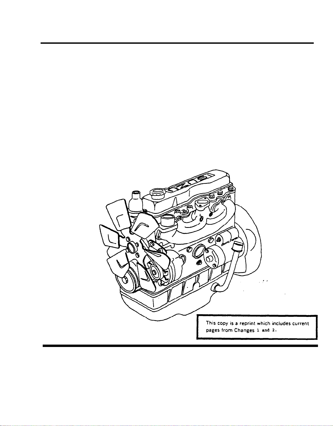
The diesel engine (FIGURE 1-1) is four cylinder, four cycle, fuel injected, naturally-aspirated, and liquid-cooled.
The firing order is 1-3-4-2. The number one cylinder is toward the fan end of the engine. The serial number is found
on left side of the cylinder body at number one cylinder location. Rotation of engine is counterclockwise as viewed
from flywheel.
ARMY TM 9-2815-254-24
AIR FORCE TO 38G1-94-2
SECTION II. EQUIPMENT DESCRIPTION AND DATA
NOTE
All locations referenced herein are given facing the flywheel end (rear)
of the engine.
1-8.
1-8.1.
1-8.2.
1-8.3.
1-8.4.
DETAILED DESCRIPTION.
Cooling System. The cooling system consists of a radiator, water pump, cooling fan, thermostat, and connecting
hoses. The fan is mounted on shaft of water pump and both are belt driven from the crankshaft pulley. The thermostat controls engine temperature and is installed in the top of engine. The function of the cooling system is to maintain a specific operating temperature of 180° to 203°F (82° to 95°C) for the engine.
Lubrication System. The lubrication system consists of the oil pan, a gerotor type oil pump, spin-on type oil filter,
and internal passages within the engine. There are two external oil lines, one for rocker arm lubrication and one
for fuel injector pump lubrication.
Fuel System. The function of the fuel system is to inject a metered quantity of clean atomized fuel into the engine
cylinders at a precise time near the end of the compression stroke of each piston. The fuel system consists of
the fuel tank, fuel filter/water separator, fuel injection pump, and the fuel injectors. The fuel tank and fuel filter/water separator are not mounted on engine. The injection pump is mounted on the front cover and is driven by the
timing gears.
Electrical System. The electrical system is 24 VDC operation and consists of an alternator, starter, externally
mounted batter and other items as required. The alternator is mounted on front of engine and is belt driven.
When the engine is operating, the alternator supplies 24 VDC to recharge the battery and maintain it at a full state
of charge. The starter is mounted on the flywheel housing and when energized engages the ring gear of the flywheel to rotate the engine.
1-3
Page 20
ARMY TM 9-2815-254-24
AIR FORCE TO 38G1-94-2
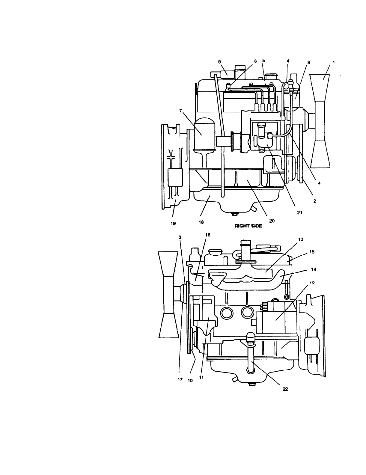
1.
Fan
2.
Fan Belt
3.
Fan Pulley
4.
Fuel Pipes
5.
Fuel Injector Pipes
6.
Injector Nozzle and Glow Plug
Oil Filter
7.
Fuel Filter Housing
8.
9.
PCV Valve
10.
Crankshaft Pulley
11.
Battery Charging Alternator
12.
Starter
13.
Intake Manifold
14.
Exhaust Manifold
Valve cover
15.
16.
Thermostat Housing
17.
Water Pump
18.
Oil Pan
19.
Flywheel Housing
Crankcase
20.
Fuel Injection Pump
21.
22.
Dipstick and Tube
1-4
FIGURE 1-1. Engine Components
Page 21

1-9. EQUlPMENT DATA.
ARMY TM 9-2815-254-24
AIR FORCE TO 38G1-94-2
1-9.1.
Leading Particulars. For a list of leading particulars, refer to TABLE 1-1.
TABLE 1-1. Table of Specifications
Model
Type
Bore/Stroke
Displacement
Horsepower Rating
Compression Ratio
Length
Width
Height
Weight
Firing Order
Injection Pump
Governor ...........................................
Injection Starting Pressure
Cylinder Compression Pressure (warm)
Valve Clearance (cold)
Lubrication System Capacity
Coolant System Capacity (engine only)
Battery Charging Alternator.
Starter..........................................................Hitachi,24VDC-3.5kw
.............................................................
......................................... Four cylinder, four cycle, liquid cooled diesel
...................................................
...............................................................................
..........................................................
.....................................................................................................
...................................................................................................................
Barber-Colman Model 10502-001-0-2
..........................................
.................................
................................................
............................................
.............................................
.......................................
lsuzu, C240 PW-28
3.38/4.01 in. (86/102 mm)
144.5 cu in. (2369 cu cm)
32 BHP @ 1800 rpm
20:1
28.9 in (736 mm)
21.0 in (535 mm)
32.1 in (815 mm)
491 Ibs (223 kg)
1-3-4-2
Kiki - PES4A
1706 psi (11,772 kPa)
441 psi (3041 kPa)
0.017 in. (0.45 mm)
1.6 gal (6.1 liters)
1.37 gal (5.2 liters)
Hitachi, 24 VDC - 20 amp
1-5
Page 22

ARMY TM 9-2815-254-24
AIR FORCE TO 38G1-94-2
SECTION III. PREPARATION FOR USE
1-10.
1-10.1. Inspection.
1-10.2. Service. Except for servicing the lubrication system all other servicing must be accomplished after engine is
lNSPECTlNG AND SERVlCING ENGINE.
This section provides information and guidance for inspecting, servicing, and installing the engine. For additional
information, also refer to end item maintenance manual.
a.
Check that all packing materials have been removed.
b.
Check engine identification plate for positive identification.
c.
Inspect engine exterior for shipping damage.
d.
Check fan belt drive for proper tension. Refer to end item maintenance manual.
e.
Inspect engine for loose or missing mounting hardware, or damaged or missing parts.
mounted in the end item, refer to end item maintenance manual and lubrication order (LO).
1-6
Page 23

CHAPTER 2
OPERATION
SECTION I. PRINCIPLES OF OPERATION
ARMY TM 9-2815-254-24
AIR FORCE TO 38G1-94-2
2-1.
2-2.
2-3.
2-4. FUEL SYSTEM.
INTRODUCTIONS
This section contains functional descriptions of the engine systems and how they are connected to the end item
COOLING SYSTEM.
The cooling system consists of a radiator, hoses, thermostat, belt driven fan, water pump, and cooling jackets
within the engine. The water pump forces coolant through passages (coolant jackets) in the engine block and
cylinder head where coolant absorbs heat from the engine. When the coolant temperature is below operating temperature, the thermostat is closed and coolant is bypassed to the water pump inlet. As coolant temperature increases to 180°F (82°C), the thermostat starts to open, restricting bypass flow and opening flow to the radiator. As
coolant temperature continues to increase to 203°F (95°C), the thermostat is fully opened, shutting off all bypass
flow and providing full flow through the radiator. Air forced through the fins of the radiator by the fan cools the
coolant pumped through the radiator. Items are added to the engine to monitor coolant temperature and to warn if
temperature exceeds a predetermined value.
LUBRICATION SYSTEM.
The lubrication system consists of an oil pan, dipstick, pump, and filter. The oil sump is a reservoir for lubricating
oil. The dipstick indicates oil level in sump. The pump draws oil from the sump through a screen which removes
large impurities. The oil then passes through a spin-on type filter where small impurities are removed. From the
filter, oil enters the cylinder head oil gallery and is distributed to the engines internal moving parts and to the fuel
injection pump. After passing through the block and pump, the oil returns to the oil sump. Items are added to moni-
tor oil pressure and to warn/stop engine if pressure drops to a dangerously low value.
2-4.1.
The fuel system consists of an external fuel tank, transfer pump, fuel filter/water separator, fuel injection pump,
fuel injectors, and piping. Fuel from an external source is supplied to the fuel injection pump. The injection pump
provides a pressurized metered quantity of clean atomized fuel through the injector nozzles into the cylinder at
a precise time near the end of the compression stroke of each piston. The fuel that is not used by the injectors
is returned to the fuel tank via an excess fuel return line.
2-1
Page 24

ARMY TM 9-2815-254-24
AIR FORCE TO 38G1-94-2
2-4.2. Extremely cold outside temperatures make starting the engine difficult. To improve engine starting, a cold weather
starting aid has been provided that features a glow plug for each cylinder. The glow plugs are energized to preheat
engine combustion air during engine preheat starting cycle.
2-5.
ELECTRICAL SYSTEM.
The electrical system consists of external mounted batteries, starter, battery charging alternator, and related relays and switches for control of the system. Battery power supplied to the starter during the start cycle energizes
the starter which engages the ring gear of the flywheel causing the engine to turn over. When engine start is com-
plete, the starter is deenergized and disengages from the flywheel. The battery charging alternator is belt driven. It
is a 20 ampere, 24 VDC alternator that when operating, supplies voltage to the 24 VDC circuit and recharges the
batteries and maintains them at a full state of charge.
2-2
Page 25

SECTION II. OPERATING INSTRUCTIONS
NOTE
Refer to end item operator’s manual.
ARMY TM 9-2815-254-24
AIR FORCE TO 38G1-94-2
2-3/(2-4 blank)
Page 26

Page 27

ARMY TM 9-2815-254-24
AIR FORCE TO 38G1-94-2
CHAPTER 3
MAINTENANCE
Section I. PREVENTIVE MAINTENANCE CHECKS AND SERVICES (PMCS)
3-1. PMCS PROCEDURES.
3-1.1.
To ensure that engine is ready for operation at all times, it must be inspected so defects can be discovered
and corrected before they result in serious damage or failure.
conjunction with performance of engine PMCS. For engine PMCS, refer to TABLE 3-1.
General.
Perform operator’s PMCS prior to or in
Table 3-1. Preventive Maintenance Checks and Services (PMCS)
Item
No.
1
2
Interval
M
QSAB H
300
750
Item
to be
Inspected
Oil Filter Change oil filter.
PCV System
Procedures Check Equipment is
for and have Not/Ready
repaired or adjusted
as necessary
Refer to paragraph
3-14.1.
NOTE
Oil filter change inter
val is a hard time
replacement to be
used when AOAP
lab is not available.
Service PCV system.
Refer to paragraph
3-20.
Available
If:
3
4
1500 Cylinder Head Torque cylinder head
Bolts
3000 Engine Valve
Clearances
bolts. Refer to
paragraph 3-27.6d.
NOTE
Valve clearance
must be checked
after cylinder head
bolt tightening has
been done. Refer to
step 3 in this table.
Adjust engine valve
clearances. Refer to
paragraph 3-26.6.
Change 2 3-1
Page 28

ARMY TM 9-2815-284-24
AIR FORCE TO 38G1-94-2
Table 3-1. Preventive Maintenance Checks and Services (PMCS) - Continued
Item
No.
5
6
7
6
Interval
M
QSAB H
Item
to be
Inspected
3000 Engine Fuel
Injectors
1500 Engine
Compression
1500 Engine Oil
Pressure
300
Fuel Injection
Pump Governor
Oil
Procedures Check
for and have
repaired or adjusted
as necessary
Remove, clean, and
test injectors. Refer
to paragraph 3-10.
Check engine compression. Refer to
paragraph 3-27.7.
Check engine oil
pressure. Refer to
paragraph 3-19.
Remove oil level
plug to check oil
level. Fill at fill plug.
Change oil if it
becomes contaminated.
Equipment is
Not/Ready
Available
If:
Engine compression
is low.
Engine oil pressure
not as specified.
3-2 Change 2
Page 29

SECTION II. TROUBLESHOOTlNG
ARMY TM 9-2815-254-24
AIR FORCE TO 38G1-94-2
3-2.
3-2.1.
TROUBLESHOOTING PROCEDURES.
Purpose of Troubleshooting Table. This section contains troubleshooting information for locating and Correcting
operating troubles which may develop in the engine. Each malfunction for an individual component unit or system
is followed by a list of tests or inspections which will help you to determine probable causes and corrective action
to take. You should perform tests/inspections and corrective actions in order listed.
This table cannot list all malfunctions that may occur, nor all tests or inspections and corrective actions. If a mal-
function is not listed or cannot be corrected by listed corrective actions. notify your supervisor.
NOTE
Before you use this table, be sure you have performed your PMCS.
Prior to performing troubleshooting procedures within this manual, perform your operator’s troubleshooting and the end item maintenance
manual troubleshooting procedures.
SYMPTOM INDEX
Troubleshooting
Malfunction
Engine Will Not Crank
Starter Operates But Engine Does Not Turn Over
Engine Cranks But Fails To Start
Engine Hard To Start or WiII Not Start
In Cold Weather
Engine Misfires or Runs Irregularly or
Stalls Frequently
Engine Does Not Develop Full Power
Engine Overheating
Excessive Oil Consumption
Low Oil Pressure
Excessive Fuel Consumption
Black or Gray Smoke
Blue Exhaust Smoke
Engine Knocks
Engine Makes Abnormal Noise
Engine Makes a Gas Leaking Noise
Detonation or Pre-Ignition
Battery Charge Ammeter Shows No Charge
When Batteries Are Low
Battery Charge Ammeter Shows Excessive
Charging After Prolonged Period
Procedures Page
3-4
3-4
3-4
3-5
3-5
3-6
3-6
3-6
3-7
3-7
3-8
3-8
3-9
3-9
3-10
3-10
3-10
3-11
Change 1 3-3
Page 30

ARMY TM 9-2815-254-24
AIR FORCE TO 38G1-94-2
TABLE 3-2 Troubleshooting
1.
2.
3.
ENGINE WILL NOT CRANK
Step 1.
Step 2.
Check for defective end item starting system.
Troubleshooting per end item maintenance manual. lf not defective, do step 2.
Check for defective starter motor and solenoid.
a Test starter and solenoid. Refer to paragraph NO TAG
b. Repair/replace defective starter and/or solenoid. Refer to paragraph 3-23.
STARTER OPERATES BUT ENGINE DOES NOT TURN OVER.
Step 1.
Step 2.
Check for worn or broken starter pinion gear and/or flywheel ring gear.
a.
Remove starter and inspect pinion gear and flywheel ring gear for damage.
Replace defective clutch assembly and/or flywheel ring gear. Refer to paragraphs 3-23 and
b.
3-31.
Crankshaft rotation restricted. Attempt to manually rotate engine. If unable to manually rotate,
repair/replace engine.
ENGINE CRANKS BUT FAILS TO START
Step 1.
Step 2.
Step 3.
Step 4.
Step 5.
Step 6.
Check for fuel being supplied to fuel injection pump.
a.
Test feed pump capacity. Refer to paragraph NO TAG. If feed pump not defective, do step 2.
b.
Repair or replace fuel feed pump. Refer to paragraph 3-11.
Check for dogged fuel filter/water separator.
a Remove and dean fuel filter Assembly, paragraph 3-9. If dean, replace water separator, re-
fer to end item maintenance manual.
Check for air in fuel system lines.
Bleed fuel system. Refer to paragraph 3-12. If fuel system is free air, do step 4.
Check for fuel injector starling pressure too Iow or spray condition improper.
a
Remove, dean and test fuel injector. Refer to paragraph 3-10. Adjust as necessary, if injector
can not be adjusted, go to b. If not defective, do step 5.
b.
Replace fuel injector. Refer to paragraph 3-10.
Check for improper fuel inject pump timing.
a.
Check fuel injection pump timing. Refer to paragraph 3-13.1. If fuel injection pump timing is
correct, do step 6.
b.
Adjust fuel injection pump timing. Refer to paragraph 3-132.
Check for defective fuel injection pump.
a. Remove and test fuel injection pump. Refer to paragraph NO TAG.
b.
Repair or replace defective fuel injection pump. Refer to paragraph 3-11.
3-4
Page 31

MALFUNCTION
TEST OR INSPECTION
ARMY TM 9-2815-254-24
AIR FORCE TO 38G1-94-2
Table 3-2. Troubleshooting - Continued
CORRECTIVE ACTION
4.
5.
ENGINE HARD TO START OR WILL NOT START IN COLD WEATHER.
step 1. Check for faulty glow plugs.
a.
Test glow plugs. Refer to paragraph 3-22.3. If glow plugs not defective, do step 2.
b.
Replace defective glow plugs. Refer to paragraph 3-22.
Step 2.
ENGINE MISFIRES OR RUNS IRREGULARLY OR STALLS FREQUENTLY.
Step 1.
Step 2.
Step 3.
Step 4.
step 5.
Step 6.
step 7.
Refer to Malfunction 3 and perform steps 1 through 5.
Check for fuel being supplied to fuel injection pump.
a.
Test feed pump capacity. Refer to paragraph 3-11.5 step aj. If feed pump not defective, do
step 2.
b.
Repair or replace fuel feed pump. Refer to paragraph 3-11.
Check for air in fuel system lines.
Bleed fuel system at fuel fitter. Refer to paragraph 3-12. If no air, do step 3.
Check for tow coolant temperature.
a.
If coolant temperature not low, do step 4.
b.
Replace defective thermostat. Refer to paragraph 3-6.
Check for fuel injector nozzle dirty, defective or leaking.
a.
Clean and test fuel injector. Refer to paragraph 3-10. If not defective, do step 5.
b.
Replace fuel injector nozzle. Refer to paragraph 3-10.
Check for improper fuel injection timing.
a.
Check fuel injection timing. Refer to paragraph 3-13.1. If fuel injection timing is correct, do
step 6.
b.
Adjust fuel injection timing. Refer to paragraph 3-13.2.
Check for defective fuel injection pump.
a.
Remove and test fuel injection pump. Refer to paragraph 3-11.5. If not defective, do step 7.
b.
Replace fuel injection pump. Refer to paragraph 3-11.
Check for valves improperly adjusted.
a.
Adjust valves. Refer to paragraph 3-26.6. if properly adjusted, do step 8.
3-5
Page 32

ARMY TM 9-2815-254-24
AIR FORCE TO 38G1-94-2
MALFUNCTION
TEST OR INSPECTION
CORRECTIVE ACTION
Table 3-2. Troubleshooting - Continued
Step 8.
ENGINE DOES NOT DEVELOP FULL POWER.
Step 1.
Step 2.
Step 3.
ENGINE OVERHEATING.
Step 1.
Step 2.
Step 3.
Step 4.
Check for low engine compression.
a.
Perform engine compression check. Refer to paragraph 3-27.7.
b.
If engine defective, repair or replace engine.
Check for blocked air intake system.
Remove blockage as found. lf no blockage is found, do step 2.
Check for air in fuel system lines.
Engine overheated.
Refer to Engine Overheating, Malfunction 7. lf not a problem, refer to Malfunction 5.
Inspect coolant level.
a.
Check engine for coolant leaks. lf engine has no leaks, do step 2.
b. Repair coolant leaks.
Check for defective thermostat.
a.
If thermostat is suspected of being defective, replace thermostat. Refer to paragraph 3-6.
b.
If engine continues to overheat, do step 3.
Check for defective water pump.
a.
Remove and check water pump for damage. If not defective, do step 4.
b.
Replace defective water pump. Refer to paragraph 3-7.
Check improper fuel pump injection timing.
Adjust fuel injection pump timing. Refer to paragraph 3-13.2.
8.
3-6
EXCESSIVE OIL CONSUMPTION.
Step 1.
Step 2.
Step 3.
Check for oil leakage.
a.
Inspect engine for oil leaks. lf no leaks, do step 2.
b.
Repair or replace defective components.
Check for blocked air intake system.
Remove blockage as found. lf no blockage, do step 3.
Check for defective intake or exhaust valve seals or valve guides.
a.
Repair or replace defective components. Refer to paragraph 3-27.4.
b.
Disassemble and inspect valve seals and guides. Refer to paragraph 3-27.2. If not defective,
replace engine.
Page 33

MALFUNCTION
TEST OR INSPECTION
ARMY TM 9-2815-254-24
AIR FORCE TO 38G1-94-2
Table 3-2. Troubleshooting - Continued
CORRECTIVE ACTION
9.
LOW OIL PRESSURE.
Step 1.
step 2.
step 3.
Step 4.
Step 5.
Step 6.
Check for improper grade of oil.
a.
Refer to end item lubrication order. If proper grade of oil, do step 2.
b.
If improper grade of oil, refer to end item maintenance manual and change oil and filter.
Check for engine running hot.
a.
Refer to Engine Overheating, Malfunction 7, in this table.
b.
If not running hot, do step 3.
Check for defective relief valve.
a.
Test oil pressure relief valve. Refer to paragraph 3-15.3. If setting is normal, do step 4.
b.
Replace defective relief valve. Refer to paragraph 3-15.
Check for clogged oil pump strainer.
Remove and clean strainer. Refer to paragraph 3-18. If not clogged, do step 5.
Check for defective oil pump.
a.
Remove and inspect oil pump for defective parts. Refer to paragraphs 3-18.1 and 3-18.2.
If not defective, do step 6.
b.
Replace oil pump. Refer to paragraph 3-18.
Check for worn rocker arm bushings.
a.
Replace rocker arm bushings. Refer to paragraph 3-26.
b.
Remove and inspect rocker arm bushings. Refer to paragraphs 3-26.1 and 3-26.3. If not
worn, replace engine.
10.
EXCESSIVE FUEL CONSUMPTION
Step 1.
Step 2.
Step 3.
Step 4.
Check for leak in fuel system.
a.
Check fuel system for leaks. If no leaks, do step 2.
b. Repair fuel system.
Check for blocked air intake system.
Remove blockage as found. If no blockage is found, do step 3.
Check for defective fuel injector.
a.
Remove, clean, and test fuel injectors. Refer to paragraph 3-10. If not defective, do step 4.
b.
Replace fuel injectors. Refer to paragraph 3-10.
Check for improper fuel injection timing.
a.
Check fuel injection pump timing. Refer to paragraph 3-13.1. If fuel injection timing is correct,
do step 5.
b.
Adjust fuel injection pump timing. Refer to paragraph 3-13.2.
3-7
Page 34

ARMY TM 9-2815-254-24
AIR FORCE TO 38G1-94-2
MALFUNCTION
TEST OR INSPECTION
CORRECTIVE ACTION
Table 3-2. Troubleshooting - Continued
Step 5.
Step 6.
Step 7.
BLACK OR GRAY SMOKE.
Step 1.
Step 2.
Step 3.
Step 4.
Defective fuel injection pump.
a.
Remove and test fuel injection pump. Refer to paragraph 3-11.5. If fuel injection pump not
defective, go to step 6.
b.
Replace fuel injection pump. Refer to paragraph 3-11.
Check for low engine compression.
a.
Perform engine compression check. Refer to paragraph 3-27.7. If compression good, do
step 7.
b.
If engine defective, repair or replace engine.
Check for valves improperly adjusted.
Adjust valves. Refer to paragraph 3-26.6.
Check for blocked air intake system.
Remove blockage as found. lf no blockage is found, do step 2.
Check for defective fuel injectors.
a.
Test fuel injectors. Refer to paragraph 3-10. If not defective, do step 3.
b.
Replace fuel injectors. Refer to paragraph 3-10.
Check for improper fuel injection pump timing.
a.
Check fuel injection pump timing. Refer to paragraph 3-13.1. If fuel injection timing is correct,
do step 4.
b.
Adjust fuel injection pump timing. Refer to paragraph 3-13.2.
Defective fuel injection pump.
a.
Remove and test fuel injection pump. Refer to paragraphs 3-11.5.
b.
Repair or replace fuel injection pump. Refer to paragraph 3-11.
12.
3-8
BLUE EXHAUST SMOKE.
Step 1.
Step 2.
Check for blocked air intake system.
Remove blockage as found. lf no blockage is found, do step 2.
Check for defective intake or exhaust valve seals or valve guides.
a.
Repair or replace defective components. Refer to paragraph 3-27.4.
b.
Disassemble and inspect valve seals and guides. Refer to paragraph 3-27.2. lf not defective,
replace engine.
Page 35

MALFUNCTION
TEST OR INSPECTION
ARMY TM 9-2815-254-24
AlR FORCE TO 38G1-94-2
Table 3-2 Troubleshooting - Continued
CORRECTIVE ACTlON
13.
14.
ENGlNE KNOCKS.
Step 1.
step 2.
step 3.
ENGINE MAKES ABNORMAL NOISE
Step 1.
Step 2.
step 3.
step 4.
step 5.
lmproper fuel injection pump timing.
a.
Check fuel injection pump timig. Refer to paragraph 3-13.1. lf fuel injection timing is correct,
do step 2.
b.
Adjust fuel injection pump timing. Refer to paragraph 3-13.2.
Check for defective fuel injector.
a.
Remove, clean, and test fuel injectors. Refer to paragraph 3-10. If not defective, do step 3.
b.
Replace fuel injectors. Refer to paragraph 3-10.
Check for engine compression.
a.
Check compression. Refer to paragraph 3-27.7.
b. lf engine defective, repair or replace engine.
Check for worn or damage water pump bearing.
a.
Check for excessive water pump shaft play at cooling fan. If not excessive, do step 2.
b.
Replace defective water pump. Refer to paragraph 3-7.
Defective alternator.
a.
Remove alternator and check for damage. Refer to paragraph 3-24.1. If not defective, do
step 3.
b.
Repair or replace alternator. Refer to paragraph 3-24.
Check for improperly adjusted valves.
check valve clearance and adjust as necessary. Refer to paragraph 3-26.6. If properly ad-
justed, do step 4.
Check for damaged rocker arm.
a.
Inspect rocker arm for damage. Refer to paragraph 3-26.3. If not damaged, do step 3.
b.
Repair or replace damaged rocker arm. Refer to paragraph 3-26.
Check for loose flywheel.
a.
Tighten bolts to specified torque. Refer to paragraph 3-31.3.
b.
Check tightness of flywheel attaching bolts. If not loose, repair or replace engine.
3-9
Page 36

ARMY TM 9-2815-254-24
AIR FORCE TO 30G1-94-2
MALFUNCTION
TEST OR INSPECTION
CORRECTIVE ACTION
Table 3-2. Troubleshooting - Continued
15.
16.
ENGINE MAKES A GAS LEAKING NOISE.
Step 1.
Step 2.
Step 3.
Check for loose or damaged exhaust manifold.
a. Inspect for damaged and attaching hardware. IF not damage or loose, do step 2.
b.
Tighten or replace exhaust manifold. Refer to paragraph 3-21.3.
Check for loose fuel injection nozzle and/or glow plugs.
a. lnspect fuel injection nozzles and glow plus for looseness.
b.
lf loose, replace washers and tighten injection nozzles (paragraph 3-10) and/or glow plugs
(paragraph 3-22.4).
Check for damage cylinder head gasket.
a. lnspect area around cylinder head gasket for evidence of gas leakage.
b.
Remove cylinder head and replace gasket. Refer to paragraph 3-27.
DETONATION OR PRE-IGNITION
Step 1.
Step 2.
Step 3.
Improper fuel injection pump timing.
a Adjust fuel injection pump timing. Refer to paragraph 3-13. lf timing is correct, proceed to
Step 2.
Defect fuel injector nozzles.
a Test fuel injection nozzles. Refer to paragraph 3-10. lf fuel injection nozzles is not defective,
proceed to Step 2.
b.
Replace fuel injection nozzles. Refer to paragraph 3-10.
Carbon build-up in compression chamber.
a.
Remove cylinder head and inspect for carbon build-up. Refer to paragraphs 3-27 and 3-32.
b.
Remove carbon and/or replace components as necessary.
lf not loose, do step 3.
17.
3-10
BATTERY CHARGE AMMETER SHOWS CHARGE WHEN BATTERIES ARE LOW.
Step 1.
Step 2. Test for defective battery charging alternator.
Step 3.
Change 1
Check for broken or loose fan belt.
a Inspect fan belt. Refer to end item maintenance
2.
b.
Adjust or replace fan belt. Refer to end item maintenance manual.
a Inspect and test battery charging alternator. Refer to paragraph 3-24.1. If alternator not de
fective, do step 3.
b.
Repair or replace battery charging alternator. Refer to paragraph 3-24.
Check for breaks or loose connections in charging circuit.
if breaks or loose connections are found, repair charging circuit. Refer to end item mainte-
nance manual.
manual. If belt not loose or broken, do step
Page 37

Table 3-2. Troubleshooting - Continued
ARMY TM 9-2815-254-24
AlR FORCE TO 38G1-94-2
18.
BATTERY CHARGED AMMETER SHOWS EXCESSIVE CHARGING AFTER PROLONGED PERIOD.
Step 1.
Step 2.
step 3.
Check for defective batteries.
a
Test batteries. Refer to end item maintenance manual. If batteries not defective, do step 2.
b. Replace batteries. Refer to and item maintenance manual.
Test for defective battery charging alternator.
a. Inspect and test battery charging alternator. Refer to paragraph 3-24.3. If alternator not de-
fective, do step 3.
b. Repair or replace battery charging alternator. Refer to paragraph 3-24.
Check for short in charging circuit.
If shorted, repair charging circuit. Refer to end item maintenance manual.
Change 1
3-11
Page 38

ARMY TM 9-2815-254-24
AIRFORCE TO 38G1-94-2
SECTION III. GENERAL MAINTENANCE
3-3.
3-3.1
GENERAL
This section provides general maintenance not found in other sections of Chapter 3.
General Instructions.
Where applicable, prior to performing engine maintenance, ensure bat-
teries are disconnecting. Failure to observe this warning could results in
severe injury or death.
Refer to end item maintenance manual for removal of any components
necessary to gain access to engine.
It is strongly recommended that bolts or nuts securing cylinder heads, covers, and doors be tightened in prop-
a
er sequence.
When assembling an engine, it is always advisable nuts, bolts, and lockwashers that have been
b.
removed from high strsss locations, in particular nuts an&or bolts from connecting rods and cylinder heads
should be replaced.
C.
When assembling an engine it is always advisable to apply a small quantity of new engine lubricating oil
(MIL-L-2104) to all moving parts. After any maintenance work on engine has bean completed, lubricating oil
and fuel levels must be checked and all safety guards installed before operating.
d.
When a new fan drive belt has been installed, check belt tension after first 20 hours of operation.
Wear protective overalls, and keep items of loose clothing dear of all hot and moving pans. Use protective
e.
barrier cream when necessary.
f.
Whenever possible, dean components and surrounding area before removing or disassembling. Take care
to exclude all dirt and debris from fuel injection equipment while it is being serviced.
3-4.
Some parts are cemented with gasket compound with others being dry. Before assembly, remove all traces
g.
of old gasket and compound. Take extreme care to exclude dirt from all gasket surfaces and gasket com-
pound from all tapped holes unless otherwise specified.
h.
It is recommended that all oil seals are replaced once they have been removed from their original position.
Seals must be installed square in housing and all lip seals must be installed with lip facing lubricant to be retained. A service tool should be used to install all oil seals and care must be taken to prevent damaging new
seal when it passes over shafts.
i.
Replace ail nuts, bolts, capscrews, and studs with damaged threads. Do not use a tap-or die to repair dam-
aged threads which may impair the strength and closeness of the threads and is not recommended.
Do not allow grease or oil to enter a blind threaded hole as hydraulic action present when bolt or stud is
j.
screwed in could split or stress housing.
k.
To check or re-torque a bolt or nut, item is slackened a quarter of a turn and then tightened to specified value.
I.
A steel ISO metric bolt, capscrew, or nut can be identified by the letter M either on head or one hexagon flat.
The strength grade will also be marked on top or one flat.
m.
On nuts with identification marks on one face the frictional area of that surface will be reduced, therefore nut
should be installed with unmarked face towards component.
n.
Service took are designed to aid disassembly and assembly procedures and their use will prevent possible
unnecessary damage to components. It is recommended that service tools are always used, some operations
cannot be safely carried out without aid of reIevant tooI.
DISASSEMBLY AND ASSEMBLY SEQUENCE FOR OVERHAUL.
The following paragraphs provide the sequence of disassembly and assembly for complete overhaul of the en-
gine. Step-by-step procedures can be found in remaining sections of Chapter 3.
3-12 Change 1
Page 39

3-4.1. Disassembly.
a.
Drain all coolant and engine oil, refer to end item maintenance manual. Check engine oil for metal contaminates.
b.
Remove fan belt and alternator, refer to paragraph 3-24.1
c.
Remove starter assembly, refer to paragraph 3-23.1.
ARMY TM 9-2815-254-24
AIR FORCE TO 38G1-94-2
If the engine has been operating and coolant is hot, allow engine to cool
before you slowly loosen filler cap and relieve pressure from cooling
system. Failure to observe this warning could result in severe personal
injury.
Use care when rotating engine on engine maintenance stand. If necessary, use a lifting device to avoid severe personal injury.
Remove glow plugs, refer to paragraph 3-22.1.
d.
e.
Remove thermostat housing with thermostat, refer to paragraph 3-6.1.
Remove water pump, refer to paragraph 3-7.1.
f.
Remove oil fitter and oil piping, refer to paragraphs 3-15.1 and 3-16.1.
g.
Remove fuel filter, refer to paragraph 3-9.1.
h.
Remove fuel injectors and piping, refer to paragraph 3-10.1.
i.
Remove fuel injection pump, refer to paragraph 3-11.1.
j.
Remove PCV assembly, refer to paragraph 3-20.1.
k.
Remove intake and exhaust manifolds, refer to paragraph 3-21.1.
I.
3-13
Page 40

ARMY TM 9-2815-254-24
AIR FORCE TO 38G1-94-2
m.
Remove rocker arm cover and rocker arm assembly, refer to paragraph 3-26.1.
n.
Remove pushrods, cylinder head assembly and cylinder head gasket, refer to paragraph 3-27.1. Check for
bent push rods and discard cylinder head gasket.
o.
Remove crank shaft pulley and front gear cover, refer to paragraph 3-25.1.
p.
Remove oil pan, refer to paragraph 3-17.1.
q.
Remove flywheel and flywheel housing, refer to paragraph 3-31.1
r.
Remove crankcase, refer to paragraph 3-29.1.
s.
Remove oil pump, refer to paragraph 3-18.1.
t.
Remove idler gear assembly, refer to paragraph 3-30.1.
u.
Remove pistons, connecting rods, and crankshaft, refer to paragraph 3-28.1.
v. Remove camshaft assembly, refer to paragraph 3-30.1.
w.
Disassemble cylinder block assembly, refer to paragraph 3-32.1.
x. Cap/cover all openings to prevent entry of foreign material.
3-4.2. Assembly.
a.
Remove all caps/covers installed during disassembly.
b.
Assemble cylinder block assembly, refer to paragraph 3-32.3.
c.
Install camshaft assembly, refer to paragraph 3-30.5.
d.
Install crankshaft, pistons, and connecting rods, refer to paragraph 3-28.5.
e.
Install idler gear assembly, refer to paragraph 3-30.5.
f.
Install oil pump, refer to paragraph 3-18.3.
g.
Install crankcase, refer to paragraph 3-29.3.
h.
Install flywheel housing and flywheel, refer to paragraph 3-31.3.
3-14
Page 41

i.
Install oil pan, refer to paragraph 3-17.3.
Install cylinder head assembly and Push rods, refer to paragraph 3-27-6.
j.
k.
install rocker arm assembly, refer to paragraph 3-26.5.
I.
install intake and exhaust manifolds, refer to paragraph 3-21.3.
m.
Install PCV assembly, refer to paragraph 3-20.3.
n.
Install fuel injection pump, refer to paragraph 3-11.6.
o.
install front gear cover and crankshaft pulley, refer to paragraph 3-25.3.
p.
Time and adjust fuel injection pump, refer to paragraph 3-13.
q.
Install fuel injectors and piping. refer to paragraph 3-10.7.
r.
Install glow plugs, refer to paragraph 3-22.4.
s.
Install fuel filter, refer to paragraph 3-9.4.
t.
Install oil filter and piping, refer to paragraphs 3-15.4 and 3-16.2.
u.
Install water pump, refer to paragraph 3-7.4.
v. Install thermostat housing with thermostat, refer to Paragraph 3-6.4.
ARMY TM 9-2815-254-24
AIR FORCE TO 36G1-94-2
w.
Install starter assembly, refer to paragraph 3-23.6.
x. Install alternator and fan belt, refer to paragraph 3-24.5.
y.
Adjust valves/rocker arm assembly, refer to paragraph 3-26.6.
z.
Install rocker arm cover, refer to Paragraph 3-26.5.
aa. Fill engine with proper oil and coolant, refer to end item maintenance manual.
ab. Perform normal standard engine performance checks.
3-15
Page 42

ARMY TM 9-2815-254-24.
AIR FORCE TO 38G1-94-2
3-5. GENERAL.
This section provides maintenance for cooling system components. Components of cooling system not mentioned in this section can be found in the end item maintenance manual.
SECTION IV. COOLING SYSTEM MAINTENANCE
3-6.
3-6.1.
THEMOSTAT AND HOUSING.
If the engine has been operating and coolant is hot, allow engine to cool
before you slowly loosen filler cap and relieve pressure from cooling
system. Failure to observe this warning could result in severe personal
injury.
Removal
a.
Drain coolant system if not already drained. Refer to end item maintenance manual.
b.
If not already done, loosen hose clamp and disconnect outlet hose from outlet pipe (2, FIGURE 3-1).
3-16
FIGURE 3-1. Thermostat and Housing
Page 43

C.
Remove two screws (1) securing outlet pipe (2) to housing (8); remove outlet pipe (2) and gasket (3). Discard
gasket (3).
d.
Lift thermostat (4) from housing.
e.
Loosen two hose clamps (10) and remove bypass hose (11) from housing (8) and water pump housing.
f.
Remove four screws (6 and 7), housing (8), and gasket (9). Discard gasket (9).
If necessary, remove plugs (5) from housing (8).
g.
3-6.2. Inspection.
a.
Inspect thermostat for excessive wear or damage.
b.
Inspect housing for cracks, corrosion, or other damage.
ARMY TM 9-2815-254-24
AIR FORCE TO 36G1-94-2
NOTE :
Note location of two shorter screws (6) for use during installation.
NOTE
If thermostat is suspected of being defective, replace thermostat.
3-6.3. Replacement.
a.
Replace thermostat if worn or damaged.
b.
Replace housing if badly corroded or damaged.
3-6.4. Installation.
a.
If removed, install plugs (5, FIGURE 3-1) in housing (8).
b.
Apply sealing compound (FORMAGASKET2) and position housing (8) with new gasket (9) on engine block
and secure with four screws (6 and 7). Install two shorter screws (6) in locations noted during removal. Tighten
all four screws to 168 in-lbs (19 Nm)
c.
Position thermostat (4) in housing (8).
3-17
Page 44

ARMY TM 9-2815-264-24
AIR FORCE TO 38G1-94-2
d.
Apply sealing compound (FORMAGASKET2) and position outlet pipe (2) and new gasket (3) on housing (8)
and secure with two screws (1). Tighten screws to 168 in-lbs (19 Nm).
e.
Install bypass hose (11) on housing (8) and water pump housing and secure with two hose clamps (10).
f.
Connect outlet hose to outlet pipe (2) and secure with hose clamp.
g.
Service coolant system, refer to end item maintenance manual.
3-7. WATER PUMP.
3-7.1.
Removal.
Do not drain coolant until coolant temperature is below operating tem-
perature prior to removal. Severe personal injury can occur.
a.
Drain coolant system if not already drained, refer to end item maintenance manual.
b.
Loosen hose clamp and remove inlet hose from water pump outlet.
c.
Remove fan drive belt, refer to end item maintenance manual.
d.
Remove four screws (1, FIGURE 3-2) securing fan (2) spacer (3), and fan pulley (4) to water pump (7); remove fan, spacer, and pulley.
NOTE
Note location of two longer screws (5) for use during installation.
e.
Remove six screws (5 and 6) securing water pump (7); remove alternator bracket (8), water pump (7) and
gasket (9). Discard gasket.
3-18
Page 45

3-7.2. Inspection.
a.
Inspect pump rotation for abnormal noise, binding, and other abnormal conditions.
b.
Inspect pump housing for cracks, corrosion, or any other damage.
ARMY TM 9-2815-254-24
AIR FORCE TO 36G1-94-2
3-7.3.
Replacement. Replace pump assembly if inspection reveals any abnormal condition, such as bearing failure, excessive end play, or abnormal rotation.
3-7.4. Installation.
a.
Apply sealant and position new gasket (9). water pump (7) and alternator bracket (8) on engine block and
secure with six screws (5 and 8). Tighten screws to 30 ft-lbs (40.6 Nm)
b.
Position fan pulley (4) spacer (3) and fan (2) on water pump (7) hub and secure with four screws (1). Tighten
screw to 72 in-lbs (8.0 Nm).
c.
Install fan drive belt, refer to end item maintenance
Ensure longer bolts (5, FIGURE 3-2) are installed in the location noted
during removal. Failure to observe this caution will result in pump not
being secured properly.
manual.
3-19
Page 46

ARMY TM 9-2815-254-24
AIR FORCE TO 38G1-94-2
3-20
FIGURE 3-2. Water Pump
Page 47

3-8. GENERAL.
This section provides maintenance for fuel system components. Components of the fuel system not mentioned in
this section can be found in end item maintenance manual.
ARMY TM 9-2815-254-24
AIR FORCE TO 38G1-94-2
SECTION V. FUEL SYSTEM MAINTENANCE
3-9.
FUEL FILTER ASSEMBLY.
3-9.1. Removal.
a.
Loosen drain plug (1, FIGURE 3-3) on bottom of filter and drain fuel.
b.
Remove fluid passage bolt (2) securing fuel tube (4) to top centerfitting of filter body (15). Remove and discard
two seals (3).
C.
If necessary to remove fuel tube (4) remove fluid passage bolt (5) securing tube to fuel injector pump. Remove and discard two seals (6). Cap openings.
NOTE
The fuel filter assembly contains no filter element. Another fuel filter is
located on the end item. Disassembly of this filter is only required to replace preformed packings or seals if suspected of leaking.
Diesel fuel is flammable and toxic to eyes, skin, and respiratory tract.
Skin/eye protection required. Avoid repeated/prolonged contact. Good
general ventilation is normally adequate.
NOTE
Drain fuel into suitable container.
d.
Disconnect fuel line from fitting (25) on side of filter body (15). Cap openings.
3-21
Page 48

ARMY TM 9-2815-254-24
AIR FORCE TO 38G1-94-2
e.
Remove fluid passage bolt (7) securing fuel tube (9) to fluid passage bolt (7). Remove and discard two seals
(8). Cap openings.
f.
Disconnect fuel return line (10) to facilitate removal of fluid passage bolt (11). Cap openings.
g.
Remove fluid passage bolt (11) securing fuel tube (13) to fitting on top of filter body (15). Removeand discard
two seals (12).
h.
Remove two bolts (14) securing filter body (15) to bracket (19); remove filter assembly.
i.
If necessary, remove two bolts (16), washers (18) and lockwashers (17) securing bracket (19); remove
bracket. Discard lo&washers (17).
3-9.2. Disassembly.
a.
Remove drain plug (1, FIGURE 3-3) and preformed packing (20) from thru-bolt (21). Discard preformed pack-
ing (20).
b.
Remove thru-bolt (21) and remove preformed packing (22), filter bowl (23), and preformed packing (24) from
body (15). Discard preformed packings (22 and 24).
c.
If replacing entire filter assembly, remove and retain fitting (25).
3-9.3. Assembly.
a.
Position new preformed packing (22, FIGURE 3-3) on thru-bolt (21). Position new preformed packing (24)
and filter bowl (23) on body (15) and secure with thru-bolt (21). Tighten thru-bolt to 22 ft-lbs (29.8 Nm).
b.
Install new preformed packing (20) and drain plug (1) into thru-bolt (21).
c.
If removed, install fitting (25).
3-9.4. Installation.
a. If removed, position bracket (19, FIGURE 3-3) on engine block and secure with two bolts (16). new lockwash-
ers (17), and washers (18).
3-22
Page 49

ARMY TM 9-2815-254-24
AIR FORCE TO 38G1-94-2
FIGURE 3-3. Fuel Filter Assembly
3-23
Page 50

ARMY TM 9-2815-254-24
AIR FORCE TO 38G1-94-2
Position filter assembly on mounting bracket and secure filter body (15) with two bolts (14). Do not tighten
b.
bolts until fuel tubes have been connected to filter and tightened.
C.
Remove caps and install fuel return line (10).
d.
Attach fuel tube (13) to fitting on top of filter body (15) with two new seals (12) and fluid passage bolt (11).
Tighten fluid passage bolt (11) to 132 in-lbs (14.9 Nm).
e.
Remove caps and attach fuel tube (9) to fluid passage bolt (11) with two new seals (8) and fluid passage bolt
(7).
f.
Remove caps and connect fuel line to fitting (25) on side of filter body (15).
If removed from fuel injection pump, remove caps and attach one end of fuel tube (4) to pump with two new
g.
seals (6) and fluid passage bolt (5).
h.
Attach other end of fuel tube (4) to top center fitting of filter body (15) with two new seals (3) and fluid passage
bolt (2).
i.
Tighten fluid passage bolts (2, 5, 7, and 11) to 132 in-lbs (14.9 Nm).
Tighten filter mounting bolts (14).
j.
k.
Ensure filter drain plug (1) is tight.
I.
Bleed engine fuel system, refer to paragraph 3-12.
m.
Operate engine and check for leaks.
3-10. FUEL lNJECTORS AND PIPING.
3-10.1. Removal.
Fuel is flammable. Keep fuel away from heat and open flame. Failure
to observe this warning could result in serious injury or death.
3-24
Page 51

ARMY TM 9-2815-254-24
AIR FORCE TO 38G1-94-2
Do not apply excessive force to injection fuel tubes. Failure to observe
this caution could damage the equipment.
NOTE
Drain fuel into suitable container.
a.
Loosen sleeve nut on fuel tubes (1, 2, 3, and 4, FIGURE 3-4) at fuel injection pump
b.
Loosen sleeve nut on fuel tubes (1, 2, 3, and 4) at fuel injector.
c.
Remove three clamp assemblies (5) and remove fuel tubes (1, 2, 3, and 4).
d.
Cap all openings to prevent entry of foreign material.
e.
At each fuel injector, remove fluid passage bolt (8) and two seals (7) securing fuel tube (10). At fuel filter, remove fluid passage bolt (8) and two seals (9); remove fuel tube (10). Discard seals (7 and 9). Cap openings.
Handle each injector carefully to prevent damage to nozzle tip.
f.
Unscrew each fuel injector (11) from block and remove washer (12) and washer (13) from each injector port.
Discard washers (12 and 13). Cap or plug all openings.
3-10.2. Disassembly (Fuel Injector).
a.
Loosen and remove cap nut (14, FIGURE 3-4) and gasket (15). Discard gasket (15).
b.
Remove adjusting screw (16).
c.
Remove washer (17), spring (18), and pushrod (19) from holder (25).
3-25
Page 52

ARMY TM 9-2815-254-24
AIR FORCE TO 38G1-94-2
3-26
FIGURE 3-4. Fuel lnjectors and Piping
Page 53

d. Remove retainer nut (20) and nozzle (21) from holder (25).
e. If necessary, remove screw (22), connector (23), and gasket (24) from holder (25). Discard gasket (24).
3-10.3. Inspection.
3-10.3.1 Fuel Injector.
a.
Remove nozzle needle from nozzle body.
Clean fuel injector, refer to paragraph 3-10.4.
b.
c.
Insert nozzle needle in nozzle body and check for smooth movement of needle inside the body. If needle does
not move smoothly after cleaning, replace nozzle.
d.
Check nozzle body and nozzle needle for damage or deformation. If either is discovered, replace nozzle assembly.
ARMY TM 9-2815-254-24
AIR FORCE TO 38G1-94-2
The nozzle needle valve and nozzle body combinations must not be in-
terchanged otherwise, injectors will not operate property.
3-10.3.2.
e.
Check both pushrod seating positions (nozzle needle and spring seat) for excessive wear and cracking. If
either is discovered, replace pushrod.
f.
Inspect threaded components for thread damage and replace as necessary.
Inspect spring for cracks or missing coil.
g.
Piping.
a.
Inspect all fuel tubes (piping) for wear, kinks, or fitting damage. Replace as necessary.
b.
Inspect fluid passage bolts for clogged passages. Clean or replace as necessary.
3-27
Page 54

ARMY TM 9-2815-254-24
AIR FORCE TO 38G1-94-2
3-10.4.
Cleaning.
Cleaning solvent is flammable and toxic to eyes, skin, and respiratory
tract. Skin/eye protection required. Avoid repeated/prolonged contact.
Good general ventilation is nom-rally adequate.
a.
Soak all parts except nozzle in a dry cleaning solvent (P-D-680) and wipe off all excess residue with a soft
cloth. Use wire brush to clean excessively dirty parts.
Clean nozzle holder mating surfaces with a piece of hard wood or a soft
cloth otherwise, damage will occur. Do not use a metal brush since
scars could cause leakage.
b.
Remove nozzle needle valve from nozzle body. Holding the needle valve by stem, only clean shaft section
and seat surface of needle valve with a piece of hardwood dipped in engine lubricating oil (ML-L-2104) or
a clean soft cloth.
c.
If a large amount of carbon residue remains and nozzle can not be cleaned well enough, dip nozzle in carbon
cleaner and repeat step b.
Compressed air used for cleaning can create airborne particles that
may enter the eyes. Pressure will not exceed 30 psig (207 kPa). Eye
protection required.
Never use sand paper, metal scraper, or other abrasive materials to
clean nozzle body and needle valve, otherwise damage will occur.
3-28
Page 55

d.
Wash all parts in dean diesel fuel. Dry with compressed air.
3-10.5. Assembly (Fuel Injector).
a.
If removed, install screw (22, FIGURE 3-4), new gasket (24), and connector (23) in holder (25).
b.
Install nozzle (21) and retainer nut (20) on holder (25).
c.
Install pushrod (19), spring (18), and washer (17) in holder (25).
d.
Install adjusting screw (16).
New gasket (15) and cap nut (14) will be installed after adjustment,
paragraph 3-10.6.
3-10.6. Test/Adjustment.
Perform step a through c if cap nut (14, FIGURE 3-4) is not loose.
a.
Place fuel injector in a vise and clamp on holder (25).
ARMY TM 9-2815-254-24
AIR FORCE TO 38G1-94-2
NOTE
NOTE
b.
Remove cap nut (14).
c.
Remove fuel injector from vise.
d.
Attach fuel injector to a fuel injector tester. Point fuel injector into a clear container.
Keep body clear of test spray. Fluid can be injected into bloodstream
causing blood poisoning and possible death.
3-29
Page 56

ARMY TM 9-2815-254-24
AIR FORCE TO 36G1-94-2
e.
Open valve on fuel injector tester and operate lever at one stoke per second.
f.
Spray should start at 1706 psi (120 kg/cm2) and a well atomized spray pattern (refer to FIGURE 3-5) should
be visible.
g.
Turn adjusting screw (16, FIGURE 3-4) as necessary to obtain starting pressure and spray pattern in step
f.
FIGURE 3-5. Fuel Injector Spray Pattern
h.
Repeat step e and operate level to hold pressure at 290 psi (20.4 kg/cm2) below opening pressure.
i.
No drops should fall from fuel injector within 10 seconds.
j.
Remove fuel injector from tester and place in a vise.
k.
Install capnut (14) and tighten to 25.5 ft-lbs (34.0 Nm).
l.
Remove fuel injector from vise.
3-10.7. Installation.
NOTE
lf existing fuel injectors are being used, ensure they are installed in loca-
tions as marked during removal.
3-30
Page 57

ARMY TM 9-2815-254-24
AIR FORCE TO 38G1-94-2
a.
Remove caps/plugs and install new washers (12 and 13, FIGURE 3-4) in each injector port.
b.
Install each fuel injector (11) and temporarity tighten them. Final tightening will be done after fuel tubes are
connected.
c.
Remove caps and position fuel tubes (1, 2, 3, and 4) between fuel injection pump and their respective fuel
injector (11). Tighten sleeve nuts on each end evenly a little at a time, to reduce undue stress on the tubes,
to 27 ft-lbs (36.6 Nm).
An improperly positioned clamp assembly (5) will result in objectionable
fuel pulsing noise and possible fuel tube rupture.
d.
Carefully position and tighten each of the three clamp assemblies (5).
e.
Tighten fuel injector screw (22) to 54 ft-lbs (73.2 Nm).
f.
Remove caps and position fuel tube (10) on each fuel injector (11) and at fuel filter. Secure to fuel fitter with
fluid passage bolt (8) and two new seals (9). Secure to each fuel injector (11) with fluid passage bolt (6) and
two new seals (7). Tighten each fluid passage bolt to 132 in-lbs (14.9 Nm)
Bleed engine fuel system, refer to paragraph 3-12.
g.
h.
Operate engine and check for leaks and proper operation.
3-11. FUEL INJECTION PUMP.
3-11.1.
Removal.
a.
Drain engine cooling and lubrication systems. Refer to end item maintenance manual.
Fuel is flammable. Keep fuel away from heat and open flame. Failure
to observe this warning could result in serious personal injury or death.
3-31
Page 58

ARMY TM 9-2815-254-24
AIR FORCE TO 38G1-94-2
b.
Disconnect fuel tubes (1, 2, 3, and 4, FIGURE 3-4) from delivery valve ports on fuel injection pump (3, FIG
URE 3-7). Cap all openings.
Disconnect fuel tubes from top and bottom of fuel feed pump (10). Cap openings.
c.
d.
Remove fluid passage bolt (1, FIGURE 3-8) from top front of fuel injection pump securing fuel tube from fuel
fitter. Remove and discard two seals (2). Cap openings.
e.
Remove fluid passage bolt (3) from side of fuel injection pump securing oil feed tube. Remove and discard
two preformed packings (4).
f.
Remove/disconnect engine speed control system from fuel injection pump. Refer to end item maintenance
manual.
g.
Rotate crankshaft pulley to align Top Dead Center (TDC) mark with pointer, refer to FIGURE 3-6.
NOTE
Drain fuel into suitable container.
3-32
FIGURE 3-6. lop Dead Center
h.
Remove four screws (1, FIGURE 3-50) securing cover (2) to front gear cover (9); remove cover (2) and pre-
formed packing (3). Discard preformed packing.
Page 59

i.
Verify alignment of Z marks on timing gears.
Support weight of fuel injection pump (3) and remove four bolts (1) and two bolts (2) securing pump to engine
j.
front plate. Remove pump (3) and packing (4). Discard packing (4).
3-11.2. Disassembly.
3-11.2.1.
a.
Keep work area clean and orderty.
b.
Record performance data for later reference. This data will facilitate detection and diagnosis of malfunctions
and defects, if any.
c.
Lay out parts in order of disassembly. This will aid in reassembling pump.
d.
Clean outer surface of pump. Remove all grease and dirt.
e.
Drain lubricating oil from pump.
ARMY TM 9-2815-254-24
AIR FORCE TO 33G1-94-2
NOTE
Note location of two longer bolts (2, FIGURE 3-7) for use during installa-
tion.
3-11.2.2.
Procedure.
a.
Mount fuel injection pump in soft-jawed vise.
b.
Attach spanner (157916-5320) to timer assembly holder (7, FIGURE 3-7), remove nut (5), and lo&washer
(6). Discard lo&washer (6).
c.
Attach extractor (157926-6220) and spanner (157916-5320) to timer assembly (7) and remove timer assembly.
d.
Remove four nuts (5, FIGURE 3-8), lockwashers (6), and washers (7) securing bracket (8) to pump; remove
bracket. Remove and discard preformed packing (10).
e.
Remove pump from vise. Mount bracket (157944-7820) on universal vise (157944-8520).
f.
Securely attach fuel injection pump to bracket using four bolts.
3-33
Page 60

ARMY TM 9-2815-254-24
AIR FORCE TO 38G1-94-2
3-34
FIGURE 3-7. Fuel Feed Pump and Timer Assembly
Page 61

ARMY TM 9-2815-254-24
AIR FORCE TO 38G1-94-2
FIGURE 3-8. Fuel Injection Pump Assembly
3-35
Page 62

ARMY TM 9-2815-254-24
AIR FORCE TO 38G1-94-2
Attach coupling (157842-4420) to camshaft and hold coupling using spanner (157916-5420). Tighten cou-
g.
pling nut.
FIGURE 3-9. Attaching Coupling (Typical)
Remove three nuts (8, FIGURE 3-7) and lockwashers (9) securing feed pump (10) to injection pump; remove
h.
feed pump (10) and preformed packing (11). Discard lockwashers (9) and preformed packing (11).
Remove two screws (11, FIGURE 3-8) securing cover (12) to side of pump; remove cover. Remove and dis-
i.
card two gaskets (13) and gasket (14).
Rotate camshaft (18) until tappet (23) is at TDC.
j.
Insert tappet holder (fabricate four each in accordance with FIGURE D-1, Appendix D) into small hole on each
k.
tappet (23) to disconnect tappet (23) from camshaft (18). Continue to rotate camshaft until one tappet holder
is installed in each of four tappets, refer to FIGURE 3-10.
FIGURE 3-10. Inserting Tappet Holder (Typical)
3-36
Page 63

ARMY TM 9-2815-254-24
AIR FORCE TO 38G1-94-2
l.
Refer to end item maintenance manual and remove governor mechanism from governor housing (17, FIGURE 3-7).
m.
Remove plug (12) and preformed packing (13) from top of governor housing (17).
n.
Remove bolt (14) with retainer (15) and six screws (16) securing housing (17) to end of pump. By tapping
housing (17) lightly with a mallet, separate it from the pump. Remove and discard gasket (18).
o.
Remove adapter (19) from pump housing (3).
p.
Lay pump on its side and remove four plugs (15, FIGURE 3-8) from bottom of pump, refer to FIGURE 3-11.
FIGURE 3-11. Removing Screw Plug (Typical)
q.
Secure pump in upright position.
r.
Remove coupling from camshaft using spanner wrench and socket wrench, refer to FIGURE 3-12.
FIGURE 3-12. Removing Coupling (Typical)
3-37
Page 64

ARMY TM 9-2815-254-24
AIR FORCE TO 38G1-94-2
s.
Remove four screws (16) securing cover (17). Tap governor end of camshaft (18) with a mallet and remove
cover (17) using two screwdrivers to pry cover out of housing.
t.
Remove camshaft (18) from drive end of housing (19).
u.
If necessary, remove bearings (20), shims (21), and rings (22) from each end of camshaft.
v. Lay pump (19) on its side.
w. Insert tappet installer (157921-0120) into bottom plug hole, refer to FIGURE 3-13.
NOTE
Note location of oil flow hole in cover (17, FIGURE 3-8).
NOTE
Note location of rings (22).
NOTE
Steps w through ac apply to each of the pumping chambers.
3-38
FIGURE 3-13. Removing Tappet Holder (Typical)
x. Push tappet (23, FIGURE 3-8) using the installer and remove tappet holder installed in step k.
y. Insert clamp (157931-6120) through camshaft opening, clamp tappet (23) and remove it from housing, refer
to FIGURE 3-14.
Page 65

FIGURE 3-14. Removing Tappet (Typical)
ARMY TM 9-2815-254-24
AIR FORCE TO 38G1-94-2
Be careful not to let plunger (24) come in contact with other parts. Place
them in clean diesel fuel in their order of removal.
z.
Using mechanical finger through bottom plug hole, remove plunger (24), lower spring seat (25) and spacer
ring (26)
aa. Remove spring (27) through bottom plug hole.
ab. Remove upper spring seat (28) and then remove cylinder sleeve (29), sleeve pinion (30), and screw (31) as
an assembly.
NOTE
If cylinder sleeve assembly is to be disassembled, scribe a mark on
sleeve (29) and sleeve pinion (30) to aid in assembly.
ac. If necessary, loosen screw (31) and remove sleeve pinion (30) from cylinder sleeve (29).
3-39
Page 66

ARMY TM 9-2815-254-24
AIR FORCE TO 38G1-94-2
Position pump in an upright position.
ad.
Remove two plate assemblies (32).
ae.
Loosen four delivery valve bodies (33).
af.
Remove delivery valve body (33) and spring (34).
ag.
ah.
Screw extractor (1579299620) into delivery valve (35). Push down the pin and remove delivery valve (35)
and gasket (36), refer to FIGURE 3-15.
FIGURE 3-15. Removing Delivery Valve
Be sure to keep each plunger (24, FIGURE 3-8) with its corresponding
plunger barrel (37). If plungers and barrels are not matched, clearances
between them may not meet standard values.
ai.
Using a finger, push plunger barrel (37) out of housing, refer to FIGURE 3-16. Attach it to its corresponding
plunger removed in step z and place it in clean diesel fuel.
Remove control rack guide screw (38, FIGURE 3-8).
aj.
ak. Withdraw control rack (39) from pump housing.
3-40
Page 67

ARMY TM 9-2815-254-24
AIR FORCE TO 38G1-94-2
FIGURE 3-16. Removing Plunger Barrel
al.
If necessary, remove and retain two bleed screws (40), two gaskets (41), three studs (42), and adapter (43).
3-11.2.3.
Feed Pump.
Use vise jaw covers to avoid damage to feed pump housing (10, FIGURE 3-7).
a.
Clamp feed pump in a vise with priming pump (20) up.
b.
Unscrew and remove priming pump (20) and preformed packing (21). Discard preformed packing.
c.
Unscrew and remove adapter (22) and preformed packing (23). Discard preformed packing.
d.
Remove both check valves (24) and springs (25).
e.
Position pump housing in vise so plug (26) faces upward.
NOTE
Tap plug (26) with a hammer to aid in loosening it.
3-41
Page 68

ARMY TM 9-2815-254-24
AIR FORCE TO 38G1-94-2
f.
Remove plug (26).
Remove gasket (27) and spring (28). Discard gasket.
g.
Remove piston (29).
h.
Turn pump housing (10) over in vise. Remove and discard retaining ring (30).
i.
Remove tappet (31) from housing and withdraw push rod (32).
j.
3-11.2.4.
Timer Assembly.
NOTE
Disassembly of the timer will only be necessary if timer does not meet
the specifications contained in paragraph 3-11.3.3. The only disassem-
bly authorized is described below.
a.
Mount base of inserter tool (157924-1620) in a vise.
If not already done, install guide bolt in base of inserter.
b.
c.
Position timer assembly (7, FIGURE 3-7) over guide bolt so that pins on inserter base enter holes in timer
assembly (7) flyweight holder.
d.
Remove six screws (33) securing gear (34) to flange (40); remove gear.
e.
Flatten tab of lockplate (36).
f.
Remove nut (35), lockplate (36), washer (37), shim (38), and washer (39) securing flange (40) to holder (7).
Discard lockplate.
3-42
Page 69

3-11.3. Inspect.
Diesel fuel is flammable and toxic to eye-s, skin, and respiratory tract.
Skin/eye protection required. Avoid repeated/prolonged contact. Good
general ventilation is normally adequate.
a.
Thoroughly wash all disassembled parts in clean diesel fuel.
b.
Check each part carefully. If they are damaged or worn excessively, replace them.
c.
Replace all gaskets and preformed packings. Do not reuse them.
3-11.3.1. Injection Pump.
a.
Check that plunger helix (FIGURE 3-17) is not damaged, that color of plunger and plunger barrel (37, FIGURE
3-8) have not changed and that Plungers move smoothly in barrels. If there are any problems, replace plunger
and barrel as an assembly.
ARMY TM 9-2815-254-24
AIR FORCE TO 38G1-94-2
FIGURE 3-17. Plunger Helix
b.
Ensure that plunger (24) slides smoothly into barrel (37) under its own weight when the assembly is inclined
approximately 60 degrees. Change plunger position by rotating it and check plunger movement several times
as above. If plunger does not slide smoothly, replace plunger and barrel as an assembly, refer to FIGURE
3-18.
3-43
Page 70

ARMY TM 9-2815-254-24
AIR FORCE TO 38G1-94-2
c.
Inspect delivery valve (35, FIGURE 3-8) piston and seat for nicks, dents, and excessive wear. lf any signs
of damage are evident, replace entire delivery valve assembly.
d.
Holding delivery valve seat, close port with finger tip. Push valve into seat and check that it is returned (by
the air inside) when released, refer to FIGURE 3-19. If valve is not returned, then fit of piston in bore is too
loose (due to wear) to justify reuse of this delivery valve assembly. Replace the entire delivery valve assembly.
FIGURE 3-18. Checking Plunger and Barrel Movement
e.
Check that control rack (39, FIGURE 3-8) is not bent. If bent, replace control rack.
FIGURE 3-19. Delivery Valve
3-44
Page 71

ARMY TM 9-2815-254-24
AIR FORCE TO 38G1-94-2
f.
Check for excessive clearance between control rack (39) and bushing (45) that is press fitted into pump housing (19). To check for end play, hold pinion and measure movement of control rack. If wear on working area
of control rack and bushing is excessive and play is more than 0.012 in. (0.3 mm), replace control rack.
g.
Check for excessive wear of gear teeth on control rack (39) and sleeve pinion (30). If backlash is more than
0.012 in. (0.3 mm), replace both control rack (39) and sleeve pinion (300).
h.
Check that flange on plunger (24) is not damaged, refer to FIGURE 3-20. If damaged, replace plunger and
barrel as an assembly.
FIGURE 3-20. Checking Plunger and Barrel for Damage
i.
Check cylinder sleeve (29, FIGURE 3-8) groove for damage or excessive wear. Replace if worn or damaged.
Check tappet (23) rollers, bushings, and pins for excessive wear, flaws, or peeling, refer to FIGURE 3-21.
j.
If damage is found, replace tappet.
FIGURE 3-21. Tappet
3-45
Page 72

ARMY TM 9-2815-254-24
AIR FORCE TO 38G1-94-2
k.
Check top surface of lower spring seat (25, FIGURE 3-8) for damage, refer to FIGURE 3-22. If damaged,
replace seat.
l.
Check camshaft (18, FIGURE 3-8) for damaged or worn cam surfaces, refer to FlGURE 3-23. Check thread
damage and keyway groove on both ends. If damaged, replace camshaft.
FIGURE 3-22. Lower Spring Seat
FIGURE 3-23. Camshaft
m.
Check bearings (20, FIGURE 3-8) for rollers deviating from inner race or peeled, damaged, or burnt surfaces,
refer to FIGURE 3-24. If found defective, refer to FIGURE 3-25 and replace defective bearings by pressing
bearings from shaft and race from cover (17, FIGURE 3-8) or governor housing (17, FIGURE 3-7).
3-46
Page 73

FIGURE 3-24. Camshaft Bearings
ARMY TM 9-2815-254-24
AIR FORCE TO 38G1-94-2
3-11.3.2.
FIGURE 3-25. Bearing Removal
Feed Pump.
a.
Inspect check valve (24, FIGURE 3-7) seats for wear or damage. If defective, replace check valve.
b.
Check piston (29) for damage or cracks. If defective, replace piston.
c.
Check tappet (31) rollers, bushing, and pin for excessive wear, flaws, or peeling. If defective, replace tappet,
refer to FIGURE 3-26.
3-47
Page 74

ARMY TM 9-2815-254-24
AIR FORCE TO 38G1-94-2
FIGURE 3-26. Feed Pump Tappet
3-11.3.3.
Tuner Assembly.
a.
Visually inspect for broken springs. If springs are broken, replace timer assembly.
b.
Inspect gear (34, FIGURE 3-7) for tooth wear. If defective, replace gear.
c.
Using feeler gage, check clearance between washer (39) and shim (38). Clearance should be 0.0008 to 0.004
in. (0.02 to 0.1 mm). If clearance is not within tolerance, change shim thickness.
3-11.4. Assembly.
3-11.4.1.
a.
Mount base of inserter tool (157924-1620) in a vise.
Install holder (7, FIGURE 3-7) on base.
b.
Install washer (39). shim (38), washer (37), new lockplate (36), and nut (35) on holder (7). Tighten nut 72 to
c.
130 ft-lbs (98 to 176 Nm).
d.
Using a feeler gage, ensure that clearance between washer (39) and shim (38) is 0.0008 to 0.004 in. (0.02
to 0.1 mm). If not change shim thickness.
Bend tab of lockplate (36) to lock nut (35).
e.
Install gear (34) and screws (33). Torque screws 5.8 to 8.7 ft-lbs (7.8 to 11.7 Nm).
f.
3-48
Page 75

ARMY TM 9-2815-254-24
AIR FORCE TO 38G1-94-2
3-11.4.2.
Feed Pump.
a.
Clamp pump housing in vise, with protected jaws, so tappet opening is facing upward.
b.
Insert pushrod (32, FIGURE 3-7) and tappet (31) into housing.
c.
Install new retaining ring (30).
d.
Turn pump housing over in vise.
e.
Install piston (29) and spring (28).
f.
Install new gasket (27) and plug (26). Apply
sealing compound (FORMAGASKET2) to threads and seating
face of plug (26). Tighten plug 63 ft-lbs (86.4 Nm).
FIGURE 3-27. Feed Pump Plug
g.
Position pump housing so priming pump opening faces upward.
h.
Install both check valves (24) and springs (25) into pump housing.
i.
Install new preformed packing (23) and adapter (22) into housing. Tighten adapter 120 in-lbs (13.6 Nm).
Install new preformed packing (21) and priming pump (20) into pump housing. Using 15/16 in. crows foot
j.
wrench, tighten priming pump 32 ft-lbs (43.4 Nm).
3-49
Page 76

ARMY TM 9-2815-254-24
AIR FORCE TO 38G1-94-2
3-11.4.3.
lnjection Pump.
a.
Mount pump housing (19, FIGURE 3-8) in bracket (157944-7820) mounted on universal vise (157944-8520)
Install four plunger barrels (37) so that locating pins in pump housing (19) mate with grooves in barrels (37).
b.
Ensure that barrels (37) cannot manually be rotated.
NOTE
If fuel injection pump is to be tested, leave springs (24), delivery valves
(35), and gasket (36) out until prestroke test is complete.
c.
Position delivery valves (35) with new gaskets (36) on plunger barrels (37).
d.
Install four springs (34) and valve bodies (33) in pump housing. Tighten as follows:
(1) Tighten to 21.7 ft-lbs (29.4 Nm).
(2) Loosen to zero torque.
(3) Retighten to 21.7 ft-lbs (29.4 Nm).
(4) Loosen to zero torque.
(5) Finally tighten to 25.3 ft-lbs (34.3 Nm).
Install control rack (39) in pump housing.
e.
f.
Install measuring device (1057826280) on nipple (45). Use measuring device to position control rack (39)
at center of travel. Install lock screw (38) in guide screw hole to lock control rack (39). Remove measuring
device.
Lay pump housing over on its side.
g.
h.
If removed, position sleeve pinion (30) on cylinder sleeve (29) so that scribed marks (from disassembly) are
aligned. Tighten screw (31) to 26.5 in-lbs (3.0 Nm).
Install cylinder sleeve (29) with split in sleeve pinion (30) facing upward.
Install guide screw (38) into back of pump housing. Ensure control rack (39) moves smoothly.
i.
3-50
Page 77

ARMY TM 9-2815-254-24
AIR FORCE TO 38G1-94-2
k.
Push control rack (39) fully toward drive side and then pull fully in opposite direction. Ensure that sleeve pinion
(30) moves through same angle from control rack’scenter position when control rack is pushed or pulled, refer
to FIGURE 3-28.
FIGURE 3-28. Checking Sleeve Pinion Movement
l.
Install upper spring seat (28) and spring (27) on plunger barrel (37) through bottom plug holes.
m.
Dip plunger (24) in clean diesel fuel and hold it with mechanical fingers. Insert plunger with lower spring seat
(25) into barrel (37) with helix facing upward and manufacturer’s mark facing downward, refer to FIGURE
3-29.
FIGURE 3-29. Inserting Plunger
3-51
Page 78

ARMY TM 9-2815-254-24
AIR FORCE TO 38G1-94-2
Refer to FIGURE D-1, Appendix D to manufacture tappet holders.
n.
Hold tappet (23, FIGURE 3-8) with clamp (157931-6120). Align tappet guide with pump housing guide groove
and insert tappet (23) and spacer ring (26) through camshaft opening, refer to FIGURE 3-30.
NOTE
FIGURE 3-30. Inserting Tappet
o.
Using tappet installer (157921-0120) through bottom plug hole, push tappet (23, FIGURE 3-8) upwards, aligning plunger flange with groove of cylinder sleeve (29).
p.
When, by pushing upward on tappet (23), plunger (24) is completely inserted into plunger barrel (37) and cylinder sleeve (29); insert tappet holder (FIGURE D-1, Appendix D) into small hole on tappet (23) body.
q.
If removed, install rings (22), shims (21), and bearings (20) on each end of camshaft (18).
NOTE
Code number (camshaft assembly mark) will be located on one end of
camshaft indicating governor end.
3-52
Page 79

ARMY TM 9-2815-254-24
AIR FORCE TO 38G1-94-2
r.
Install cover (17) so oil flow hole is facing as noted in disassembly on drive end and secure with four screws
(16). Tighten screws 72 in-lbs (8.1 Nm).
s.
Apply adhesive (242) and install four plugs (15) in bottom of pump. Tighten plugs 47 ft-lbs (63 7 Nm)
t.
Place pump in upright position.
u.
Install adapter (19, FIGURE 3-7) in pump housing (3).
v.
Insert camshaft (18, FIGURE 3-8) into pump housing from governor end.
w.
Position new gasket (18, FIGURE 3-7) and governor housing (17) on pump housing and secure with one bolt
(14), retainer (15), and six screws (16). Tighten bolt (14) to 150 in-lbs (16.9 Nm) and screws (16) to 72 in-lbs
(8.1 Nm).
If removed, install new preformed packing (13) and plug (12) in top of governor housing (17).
x.
Checkcamshaft end play. Using a dial indicator measure end play. End play should be 0.001 to 0.002 in. (0.03
y.
to 0.05 mm). If end play is not within limits, remove camshaft and change thickness of shims (21, FIGURE
3-8) and recheck end play.
z.
Check control rack (39) sliding resistance by tipping pump back and forth. Check that rack moves freely.
aa. Using measuring device (1057826280) check the stroke of control rack (39). The stroke should be 0.83 in.
(21 mm) from position where control rack is fully pushed toward governor to position where it is fully pulled
toward drive end. If stroke is not 0.83 in. (21 mm) it will be necessary to change engagement of sleeve pinions
(30) with control rack to obtain proper stroke.
ab. Attach coupling (1578424420) to camshaft and hold coupling using spanner (157916-5420). Tighten nut on
coupling.
ac. Rotate camshaft (18) until tappet (23) is in TDC position.
ad. Remove tappet holders (FIGURE D-1, Appendix D) and continue to rotate camshaft until all the tappet holders
are removed. Confirm that camshaft rotates freely by manually rotating camshaft slowly.
3-53
Page 80

ARMY TM 9-2815-254-24
AIR FORCE TO 38G1-94-2
ae. Refer to end item maintenance manual and install governor mechanism.
af.
Install two plate assemblies (32) to valve bodies (33). Tighten screw 36 in-lbs (4.1 Nm).
ag. Perform fuel injection pump test, refer to paragraph 3-11.5.
ah. Position new preformed packing (11, FIGURE 3-7) and feed pump (10) on pump housing and secure with
three new lockwashers (9) and nuts (8).
ai.
Position cover (13, FIGURE 3-8) with new gasket (14) on side of pump housing and secure with two new
gaskets (12) and screws (11).
aj.
Position bracket (8) and new gasket (10) on drive end of housing and secure with four washers (7), new lock-
washers (6), and nuts (5).
ak. Install timer assembly on camshaft and secure with new lockwasher (6, FIGURE 3-7) and nut (5). Attach
spanner (157916-5320) to timer assembly to hold it while tightening nut (5) to 45 ft-lbs (61 Nm).
3-11.5. Testing.
a.
If pump was not disassembled for cleaning and inspection, refer to paragraph 3-11.2.2 steps a thru d.
b.
If not already installed, attach coupling (157842-4420) to camshaft and hold coupling using spanner (157916-
5420). Tighten nut on coupling using socket wrench.
c.
If not removed, remove feed pump, paragraph 3-11.2.2, step h.
d.
If not removed, remove cover (13, FIGURE 3-8).
e.
Remove pump from soft-jawed vice and mount pump on test stand.
NOTE
Refer to TABLE 3-1 for a listing of fuel pump test specifications.
f.
Remove delivery valve bodies (33), springs (34), gaskets (36), and valves (35). Reinstall delivery valve bo-
dies.
3-54
Page 81

ARMY TM 9-2815-254-24
AIR FORCE TO 38G1-94-2
g.
Connect fuel pipes and injection pipes. Refer to TABLE 3-2 for correct sizes.
h.
Plug feed pump opening with plastic plug. Fill camshaft chamber with engine lubricating oil (MIL-L-2104) (80
cc). Fill governor chamber with engine oil, refer to PMCS chart (TABLE 3-1).
i.
Remove control rack cap and attach measuring device (105782-6280).
Remove control rack guide screw (38) and lock control lever rack at 0.472 in. (12 mm) using locking screw.
j.
k.
Attach measuring device (105782-4020) to pump housing No. 2 cylinder. Measuring needle must rest on tappet guide pin.
l.
Place No. 2 cylinder cam in bottom dead center (BDC) position. Set dial gage indicator to zero (0).
NOTE
Manually rotate camshaft by hand and ensure that indication of dial
gage indicator varies with change in cam lift.
FIGURE 3-31. Measuring Device Installed (Typical)
m.
Supply test oil to injection pump at as low a pressure as possible (2.8 psi (19.6 kPa)
3-55
Page 82

ARMY TM 9-2815-254-24
AlR FORCE TO 36G1-94-2
TABLE 3-1. Fuel Pump Test Specifications
3-56
Page 83

ARMY TM 9-2815-254-24
AIR FORCE TO 38G1-94-2
If pre-stroke is not 0.087 to 0.091 in. (2.20 to 2.30 mm), adjust as follows:
p.
(1) Rotate camshaft until No. 2 cam reaches TDC position.
(2)
Insert plunger spring holder (157931-4100) between lower spring seat (25. FIGURE 3-8) and tappet (23).
(3) Remove spacer ring (26) and install spacer ring that will provide desired pre-stroke. Spacer rings are
available in 0.002 in. (0.05 mm) steps.
(4) Remeasure No. 2 cylinder’s pre-stroke.
Set pump test stand flywheel pointer to an arbitrary angle graduation, with No. 2 cam placed in beginning of
q.
injection position.
r.
Ensure test oil stops flowing from measuring device pipe in this position.
Do not move flywheel pointer after it has been placed in this position.
Remove measuring device from No. 2 cylinder.
s.
Supply test oil at high pressure to injection pump.
t.
u.
Open nozzle holders overflow valves so test oil flows.
Measure beginning-of-injection positions in order of injection.
v.
Rotate camshaft until test oil stops flowing from overflow pipe.
w.
Read pointer indication on flywheel.
x.
If angle interval is not between 89.5 and 90.5 degrees between each cylinder in firing order (1-3-4-2), adjust
y.
using spacer ring (26). If oil stops flowing prematurely, decrease thickness of shim, if oil stops flowing too late,
increase thickness of shim.
Confirm that camshaft rotates smoothly by manually rotating camshaft slowly
z.
3-57
Page 84

ARMY TM 9-2815-254-24
AIR FORCE TO 38G1-94-2
aa. Install valves (35), gaskets (36), springs (34), and bodies (33), refer to paragraph 3-11.4.3.
Ensure fuel injection pump is bled of all air before doing following steps.
ab. Set test stand for an inlet pressure of 23 psi (1.6 Kg/cm2).
ac. Ensure control rack is at 0.472 in. (12 mm) position, pump speed at 1450 rpm and plunger strokes for 1000.
ad. Operate test stand and measure fuel injection quantity for each cylinder. Each cylinder should measure 42
to 44 cc with + 1.08 cc between cylinders.
ae. If fuel injection quantity is not as specified, adjust as follows:
(1) Loosen sleeve pinion screw (31).
(2) Rotate cylinder sleeve (29) clockwise or counterclockwise using an appropriate tool. Rotating cylinder
sleeve towards governor increases fuel injection quantity.
af.
Repeat steps ab thru ae for the following settings.
NOTE
NOTE
Scribe a mark to identify starting point.
(1) Pump speed 350 rpm.
(2) Plunger strokes 1000.
(3) Control rack at 0.299 in. (7.6 mm) position.
(4)
Each cylinder should measure 6.9 to 9.1 cc with + 1.12 cc between cylinders.
ag. Remove rack lock screw from pump housing and reinstall control rack guide screw (38).
3-58
Page 85

ARMY TM 9-2815-254-24
AIR FORCE TO 38G1-94-2
ah. Perform feed pump suction test as follows:
(1) Install feed pump, paragraph 3-11.4.2.
(2) Attach a 6.5 ft (2 m) length of 0.315 in. (8 mm) ID pipe to suction port of feed pump and insert other end
into fuel container. Refer to FIGURE 3-32.
(3) Attach pipe to discharge port of feed pump and insert other end into empty container.
NOTE
Ensure a suction head of approximately 3.3 ft (1 m).
FIGURE 3-32. Feed Pump Test
(4) Operate injection pump at 100 rpm.
(5) Fuel oil must be discharged in less than 60 seconds.
ai. Perform feed pump priming pump test as follows:
(1)
Pump should be piped as in step ah, refer to FIGURE 3-33.
(2) Fully loosen priming pump’s screw cap.
(3) Operate priming pump at 60 to 100 strokes per minute.
(4) Fuel oil must be discharged in less than 25 strokes.
3-59
Page 86

ARMY TM 9-2815-254-24
AIR FORCE TO 38G1-94-2
aj.
Perform feed pump capacity test as follows:
FIGURE 3-33. Priming Pump Test
NOTE
Feed pump can be tested for capacity while installed on engine. Discon-
nect discharge hose and insert in measuring container. Crank engine
for 15 seconds. Supply rate should be at least 60 cc. Replace feed
pump if it fails to meet supply rate.
(1)
Pump should be piped as in step ah, except place end of discharge pipe in a measuring cylinder, refer
to FIGURE 3-34.
(2) Operate injection pump at speeds specified in TABLE 3-2 and check for corresponding supply rate.
3-60
Page 87

FIGURE 3-34. Capacity lest
TABLE 3-2. Capacity Test
ARMY TM 9-2815-254-24
AIR FORCE TO 38G1-94-2
ak. Perform feed pump feed pressure measurement as follows:
(1) Pump suction as piped in step ah, refer to FIGURE 3-35.
(2) Pump discharge connected to test stand pressure gage
(3) Operate injection pump at 600 rpm.
(4)
Ensure that feed pump maintains a feed pressure of 25.6 to 35.5 psi (176.5 to 244.8 kPa)
al.
Perform feed pump air tightness test as follows:
(1)
Remove feed pump from pump housing. Refer to paragraph 3-11.2.2, step h.
3-61
Page 88

ARMY TM 9-2815-254-24
AIR FORCE TO 38G1-94-2
FIGURE 3-35. Feed Pump Pressure Test
(2) Install plug in discharge port.
(3) Connect an air supply to suction port and apply a pressure of 28.5 psi (196.5 kPa).
(4)
Immerse feed pump in a container of diesel fuel and check for air leakage. There must be no air leakage.
(5) Install feed pump on pump housing. Refer to paragraph 3-11.4.2.
3-62
FIGURE 3-36. Air Tightness Test
Page 89

am. Remove coupling from camshaft.
an. Install cover (13, FIGURE 3-8) with new gasket (14) and secure with two new gaskets (12) and screws (11).
ao. Position bracket (8) and new gasket (10) on drive end of housing and secure with four washers (7) new lock-
washers (6), and nuts (5)
ap. Install timer assembly on camshaft and secure with new lockwasher (6, FIGURE 3-7) and nut (5). Attach
spanner (157916-5320) to timer assembly to hold it while tightening nut (5) to 45 ft-lbs (61 Nm)
3-11.6. Installation.
a.
Disconnect and remove spring (1, FIGURE 3-37).
b.
Remove stud (2) and washer (3).
c.
Position pump in a pan to collect any oil which may be contained in governor housing.
d.
Remove two screws (4) and four screws (5).
ARMY TM 9-2815-254-24
AIR FORCE TO 38G1-94-2
NOTE
If a replacement injection pump does not include a mechanical governor, skip steps a thru g and proceed with step h.
e.
Partially separate cover (6) from housing. While holding cover in place with one hand, disconnect spring (8)
and link (9) from inside housing. This will allow separating cover (6) from housing.
Remove gasket (10).
f.
Using a hammer and screwdriver, loosen and remove nut (11) and washer (12). Remove flyweight assembly
g.
(13).
Position fuel injection pump and new packing (4, FIGURE 3-7) on engine front plate, aligning pump gear set-
h.
ting mark ‘Z’ with camshaft gear setting mark ‘z-z’. Secure pump with six bolts (1 and 2), tighten bolts 168
in-lbs (18.9 Nm).
3-63
Page 90

ARMY TM 9-2815-254-24
AIR FORCE TO 38G1-94-2
i.
Install engine front cover access plate, refer to paragraph 3-25.3 step h.
Connect/assemble engine speed control system to fuel injection pump. Refer to end item maintenance manu-
j.
al.
Position oil feed tube to side of pump and secure with two new preformed packings (4, FlGURE 3-8) and fluid
k.
passage bolt (3). Tighten bolt to 132 in-lbs (14.9 Nm).
l.
Remove caps and position fuel tube from fuel filter on top front of fuel injection pump and secure with two
new seals (2) and fluid passage bolt (1). Tighten bolt to 132 in-lbs (14.9 Nm)
m.
Remove caps and connect fuel tubes to top and bottom of fuel feed pump (10, FIGURE 3-7).
n.
Remove caps and connect fuel tubes to delivery valve ports on fuel injection pump, refer to paragraph 3-10.7,
step c.
3-64
FIGURE 3-37. Removal of Mechanical Governor
Page 91

o.
Service engine cooling and lubrication systems, refer to end item maintenance manual.
p.
Bleed air from fuel system, refer to paragraph 3-12.
q.
Operate engine and check for leaks.
3-12. BLEEDING AND PRIMING FUEL SYSTEM.
3-12.1.
a.
Loosen priming pump cap on fuel injection pump.
b.
Prime fuel injection pump several times.
c.
Loosen bleeder screw (40, FIGURE 3-8) on fuel injection pump.
Fuel is flammable. Keep fuel away from heat and open flame. Failure
to observe this warning could result in severe personal injury or death.
ARMY TM 9-2815-254-24
AIR FORCE TO 38G1-94-2
NOTE
d.
Operate priming pump (20, Figure 3-7) until no more bubbles are visible in fuel being discharged from bleeder
screws.
e.
Retighten bleeder screws and priming pump cap securely after bleeding.
3-13.
FUEL lNJECTlON PUMP TIMING.
3-13.1. Checking Procedure.
a.
Check that notched line on injection pump fixing flange is aligned with injection pump mounting flange’s
notched line.
b.
Align crankshaft pulley TDC mark with pointer.
c.
Rotate crankshaft pulley counterclockwise approximately 30 degrees.
d.
Disconnect injection pipe from delivery valve No. 1.
Drain fuel into suitable container.
3-65
Page 92

ARMY TM 9-2815-254-24
AIR FORCE TO 38G1-94-2
e.
Remove No. 1 plate assembly (32, FIGURE 3-8), valve body (33), spring (34); gasket (36). and valve (35).
f.
Install valve body (33) and tighten to 31 ft-lbs (42.0 Nm).
Take care to avoid entry of dirt or foreign particles in fuel injection pump
while delivery valve is removed. Otherwise, damage to pump could occur.
g.
Hold fuel control lever to full fuel position.
h.
Slowly turn crankshaft pulley clockwise and at same time operate priming pump to cause fuel to flow from
No. 1 delivery valve.
i.
When fuel stops flowing from No. 1 delivery valve, stop pumping and stop rotating crankshaft. This is correct
fuel injection timing.
Observe and ensure that crankshaft pulley middle timing mark (18 degrees) is aligned with pulley.
j.
k.
Blow remaining fuel from No. 1 delivery valve holder and check that no fuel flows as pumping is continued.
I.
Remove delivery valve body (33). Install valve (35), gasket (38), spring (34), valve body (33), and plate as-
sembly (32), refer to paragraph 3-11.4.3, steps c, d, and af.
m.
Reconnect injection pipe to No. 1 delivery valve, refer to paragraph 3-10.7, step c.
Operating engine with priming pump cap in unscrewed position will re-
sult in priming pump failure.
n.
Tighten priming pump cap.
3-66
Page 93

3-13.2. Adjustment Procedure.
a.
Align timing pointer at timing gear case and middle (18 degrees) injection timing notch line on crankshaft
pulley.
b.
Disconnect injection pipe from delivery valve No. 1. Cap openings.
c.
Remove No. 1 plate assembly (32, FIGURE 3-8), valve body (33), spring (34), gasket (36), and valve (35).
refer to paragraph 3-11.2.2.
d.
Install valve body (33) and tighten to 31 ft-lbs (42.0 Nm).
Take care to avoid entry of dirt or foreign particles in fuel injection pump
while delivery valve is removed. Otherwise, damage to pump could occur.
e.
Hold fuel control lever to full fuel position.
Injection timing adjustment is done by pivoting injection pump at drive
shaft. Pivot pump body toward outside of engine to advance timing. Pivot pump body toward inside of engine to retard timing.
f.
Disconnect other injection pipes at delivery valves to allow pump to pivot easily. Cap openings.
ARMY TM 9-2815-254-24
AIR FORCE TO 38G1-94-2
NOTE
g.
Loosen four nuts (5) mounting pump and pivot pump body.
NOTE
Movement of 0.04 in. (1.0 mm) corresponds to approximately 2 degrees
in crank angle.
h.
Operate priming pump to allow fuel to flow from No. 1 delivery valve.
3-67
Page 94

ARMY TM 9-2815-254-24
AIR FORCE TO 38G1-94-2
i.
While continuing to pump as described in step h, pivot pump body toward inside or outside of engine until
fuel stops flowing from No. 1 delivery valve. This is the correct fuel injection timing.
j.
Blow remaining fuel from No. 1 delivery valve holder and check that no fuel flows as pumping is continued.
Remove fuel priming pump and PCV hoses as necessary to torque
nuts.
k.
Tighten four nuts (5) securing pump to 168 in-lbs (19.0 Nm).
l.
Remove delivery valve body (33). Install valve (35), gasket (36), spring (34), and valve body (33), refer to
paragraph 3-11.4.2.
m.
Remove caps and reconnect injection pipes to delivery valves, refer to paragraph 3-10.7.
Operating engine with priming pump cap in unscrewed position will re-
sult in priming pump failure.
n.
Tighten priming pump cap.
NOTE
3-68
Page 95

SECTION VI. LUBRICATION SYSTEM
ARMY TM 9-2815-254-24
AIR FORCE TO 38G1-94-2
3-14.
OIL FILTER.
3-14.1. Cartridge Replacement.
a.
Drain lubrication system, refer to end item maintenance manual.
b.
Loosen cartridge (1, FIGURE 3-38) by turning counterclockwise with a filter wrench.
Discard used cartridge.
c.
d.
Wipe filter head (2) with a clean rag.
Apply light coat of oil to new cartridge (1) gasket.
e.
f.
Place cartridge on filter head (2) and turn clockwise until cartridge is hand-tight on head.
Using filter wrench, turn cartridge an additional 1 to 1-1/4 turns.
g.
h.
Service lubrication system, refer to end item maintenance manual.
i.
Operate engine and check for leakage.
3-14.2. Removal.
a.
Drain lubrication system, refer to end item maintenance manual.
b.
Remove four screws (3, FIGURE 3-38) securing filter head (2) to engine; remove filter head and
o-ring (4).
Cover opening to prevent entry of dirt.
c.
3-14.3. Installation.
a.
Wipe engine and filter head (2, FIGURE 3-38) mating areas with a clean rag.
b.
Install o-ring (4). Position head (2) on engine and secure with four screws (3). Tighten screws to
168 in-lbs (19.0 Nm).
NOTE
Cartridge (1) does not have to to be removed to remove head.
Change 2 3-69
Page 96

ARMY TM 9-2815-254-24
AIR FORCE TO 38G1-94-2
c.
Install cartridge (1) if necessary, refer to paragraph 3-14.1.
d.
Service lubrication system, refer to end item maintenance manual.
e.
Operate engine and check for leakage.
3-15.
3-15.1.
OIL PRESSURE RELIEF VALVE.
Removal.
a.
Drain lubrication system, refer to end item maintenance manual.
b.
Remove oil pressure relief valve (5, FIGURE 3-38) and o-ring (6).
c.
If necessary, remove plug (7) and seal (8). Discard seal (8).
3-15.2. lnspection.
a.
Inspect oil pressure relief valve (5, FIGURE 3-38) for damaged threads or other damage.
b.
Inspect plug (7) for damage.
FIGURE 3-38. Oil Filter
3-70 Change 2
Page 97

ARMY TM 9-2815-254-24
AIR FORCE TO 38G1-94-2
3-15.3.
Testing.
a.
Tag, disconnect, and remove oil pressure sending unit, if supplied.
b.
Install oil pressure gage (0-150 psi).
Start engine and check oil pressure relief valve opening. Valve should open between 82.5 to 88.2
c.
psi (568 to 608 kPa).
d.
Replace oil pressure relief valve if valve fails to open as specified above.
e.
Remove oil pressure gage and install oil pressure sending unit (if supplied). Connect electrical
connection and remove tag.
3-15.4. Installation.
a.
If removed, install plug (7) with new seal (8). Torque plug between 18.1 to 25.3 ft-lbs (24.5 to
34.3 Nm).
b.
Install oil pressure relief valve (5) and o-ring (6). Torque relief valve between 18.1 to 25.3 ft-lbs
(24.5 to 34.3 Nm)
Service lubrication system, refer to end item maintenance manual.
c.
d.
Operate engine and check for leakage.
3-16. OIL PIPING.
3-16.1. Removal.
a.
Drain lubrication system, refer to end item maintenance manual.
b.
Remove fluid passage bolt (1, FIGURE 3-39) securing valve rocker oil feed pipe (3). Remove pipe
and two gaskets (2). Discard gaskets (2).
c.
Remove two fluid passage bolts (4) and bolt (6) securing fuel injection pump oil pipe (7). Remove
pipe and four gaskets (5). Discard gaskets (5).
Change 2 3-71
Page 98

ARMY TM 9-2815-254-24
AIR FORCE TO 38G1-94-2
3-72
FIGURE 3-39. Oil Piping
Page 99

3-16.2. Installation.
Position fuel injection pump oil pipe (7, FIGURE 3-39) and secure with four new gaskets (5), two
a.
fluid passage bolts (4), and bolt (6). Tighten bolts (4) to 84 in-lbs (9.5 Nm).
Position valve rocker oil fuel pipe (3) and secure with two new gaskets (2) and fluid passage bolt
b.
(1). Tighten bolt to 84 in-lbs (9.5 Nm).
Service lubrication system, refer to end item maintenance manual.
c.
Operate engine and check for leaks.
d.
ARMY TM 9-2815-254-24
AIR FORCE TO 35G1-94-2
3-17.
OIL PAN.
3-17.1. Removal,
Drain lubrication system, refer to end item maintenance manual.
a.
b. Disconnect PVC hose.
Remove dipstick (I, FIGURE 340) and gasket (2). Discard gasket.
c.
Remove screw (3) and washer (4) securing dipstick tube.
d.
FIGURE 3-40. Oil Pan Assembly
Change 2
3-73
Page 100

ARMY TM 9-2815-254-24
AIR FORCE TO 38G1-94-2
e.
Support oil pan and remove thirty screws (5) securing oil pan. Remove oil pan (6) and gasket (6).
Discard gasket.
f.
If not removed, remove drain plug (8) and gasket (9).
3-17.2. Inspection.
a.
Inspect dipstick (1, FIGURE 3-40) for legibility. Replace if damaged.
b.
Inspect gasket (2) for deterioration and replace as necessary.
c.
Inspect oil pan (6 for cracks, dents, or other damage. Replace if damaged.
3-17.3. Installation.
a.
Wipe crankcase flange and oil pan flange and remove any traces of oil pan gasket or liquid
gasket.
b.
Apply an even coat of sealing compound (FORMAGASKET2) to crankcase flange.
c.
Affix new gasket (7, FIGURE 3-40) to crankcase flange.
d.
Remove screw (3) and washer (4) securing tube.
e.
Position oil pan (6) and install all thirty screws (5) hand-tight. Tighten screws to 72 in-lbs (8.1 Nm)
starting at point ‘A’ and ‘B’ alternately and work in a counterclockwise direction from each of these
points until all thirty screws are tightened.
f.
Install screw (3) and washer (4) secunig tube. Tighten to 168 in-lbs (19 Nm).
Install oil drain plug (8) with new gasket (9).
g.
h.
Install dipstick (1) and new gasket (2).
i.
Connect PCV hose.
Service lubrication system, refer to end item maintenance manual.
j.
k.
Operate engine and check for leaks.
3-74
Change 2
 Loading...