

Ironman Fitness 350r User Manual
Owner’s Manual
Ironman 350r Recumbent
Customer Service
1.800.750.IRON
1.800.750.4766
4009 Distribution Drive
Suite 250
Garland, TX 75041
www.ironmanfitness.com
CAUTION! Read all precautions
and instructions in this manual
before using this equipment.
SERIAL TAG IS LOCATED ON THE FRAME
Model Name: 350r
Date of Purchase:
Serial Number:
315-00125
11/07 Rev A

Table of Contents
Important Safety Information 3
Assembly 5
Console Instructions 11
Monitoring Your Heart Rate 16
Warm-Up Exercises 18
Moving Instructions 21
Parts List 22
Exploded Views 23
Warranty Information 24
22

Important Safety Information
WARNING! Before using this unit or starting any exercise program, consult your physician.
This is especially important for persons over the age of 35 and/or persons with pre-existing
health problems. The manufacturer or distributor assumes no responsibility for personal injury
or property damage sustained by or through the use of this product.
WARNING! To reduce the risk of electrical shock, burns, fire, or other possible injuries to the
user, it is important to review this manual and the following precautions before operation.
SAFETY PRECAUTIONS AND TIPS
1. It is the owner's responsibility to ensure that all users of this unit have read the Owner's
Manual and are familiar with warnings and safety precautions.
2. This unit has a user maximum capacity of 300 pounds.
3. The unit should only be used on a level surface and is intended for indoor use only. The
unit should not be placed in a garage, patio, or near water and should never be used while
you are wet. Ironman Fitness recommends a mat be placed under the unit to protect floor
or carpet and for easier cleaning.
4. Follow safety information in regards to plugging in your unit. Do not run the power cord
underneath your unit. Do not operate the unit with a damaged or frayed power cord.
5. Wear comfortable, good-quality walking or running shoes and appropriate clothing. Do not
use the unit with bare feet, sandals, socks or stockings.
6. Always examine your unit before using to ensure all parts are in working order.
7. Allow the unit to fully stop before dismounting.
8. Pets should never be allowed near the unit.
9. Do not leave children unsupervised near or on the unit.
10. Never operate the unit where oxygen is being administered, or where aerosol products are
being used.
11. Never insert any object or body parts into any opening.
12. For safety and to prevent damage to your unit, no more than one person should use the
unit at a time.
13. Always unplug the unit before cleaning and/or servicing. Service to your unit should only be
performed by an authorized service representative, unless authorized and/or instructed by
the manufacturer.
14. Failure to follow these instructions will void the unit warranty.
3
Important Safety Information
TRANSPORT WHEELS
SEAT PAD
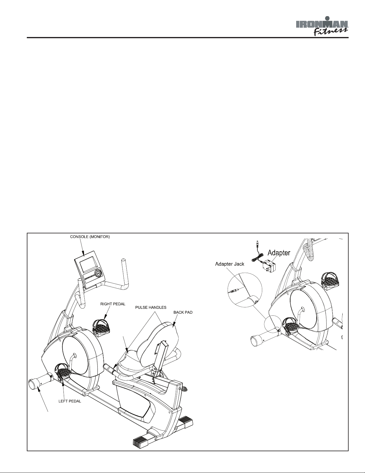
Thank you for purchasing the Ironman 350r Recumbent Bike! The quality product you have
chosen was designed to meet your needs for cardiovascular exercise. Before you start, please
read the Owner’s Manual and become familiar with the operation of your new unit.
Remember to take time to perform stretching exercises, provided in this manual, to help avoid
injury.
If you are taking medication, consult your physician to see what effect the medication will have
on your exercise heart rate.
If you have heart problems, you are not active, and/or are over the age of 35 years, do not
use the pre-set programs or start an exercise program without first contacting and receiving
approval from your physician.
To avoid the risk of electrical shock, always keep the console dry. Do not spill liquids on the
console. Ironman Fitness recommends a sealed water bottle for beverages consumed while
using the unit.
Please review the following drawing below to familiarize yourself with the listed
parts.
4
Assembly
Getting Started - The Ironman 350r will require some assembly. Unpack the box in a clear
area. Remove packing material. Do not dispose of packing material until assembly is complete
and unit is working properly. Place the unit on a clean level surface for assembly. Make sure
there is easy access to an electrical outlet. Before assembling, the unit should be placed as
close as possible to its final location. If you are missing any parts, please call Ironman Fitness
at 1-888-340-0482. Tools have been provided to assist with product assembly.
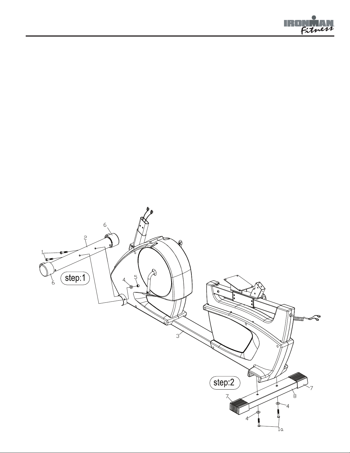
Figure 1
Step 1:
Remove the two hex head bolts from the
front stabilizer. Attach the front stabilizer
(2) onto the front of main frame (3) using
hex head screws (1), washers (4) and cap
nuts (5).
Step 2:
Remove the two hex head bolts from the
rear stabilizer. Attach the rear stabilizer
(8) onto the front of the main frame (3)
using carriage bolts (1a) and washers (4).
5
Assembly
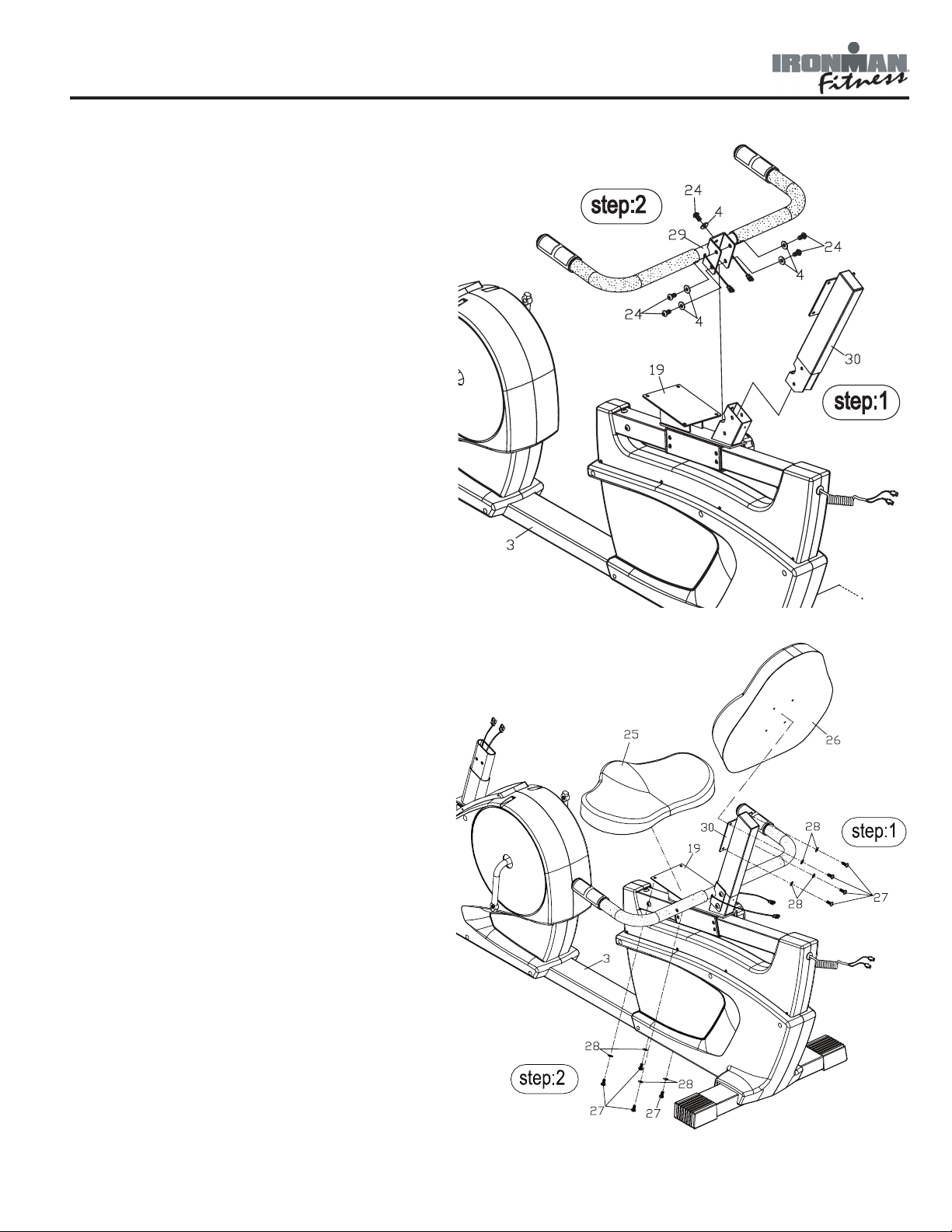
Figure 2
Step 1:
Slide the seat carriage slider (30) into the
seat carriage (19). Note: The seat car-
riage slider will be secured in the following step.
Step 2:
Attach the seat handlebar (29) to the seat
carriage (19) using hex head screws (24)
and washers (4).
Figure 3
Step 1:
Attach the back pad (26) to the seat
slider (30) using screws (27) and washers (28). Note: Screws (27) and washers
(28) are located in hardware bag.
Step 2:
Attach the seat pad (25) to the seat carriage (19) using screws (27) and washers (28). Note: Screws (27) and washers
(28) are located in hardware bag.
6
Assembly
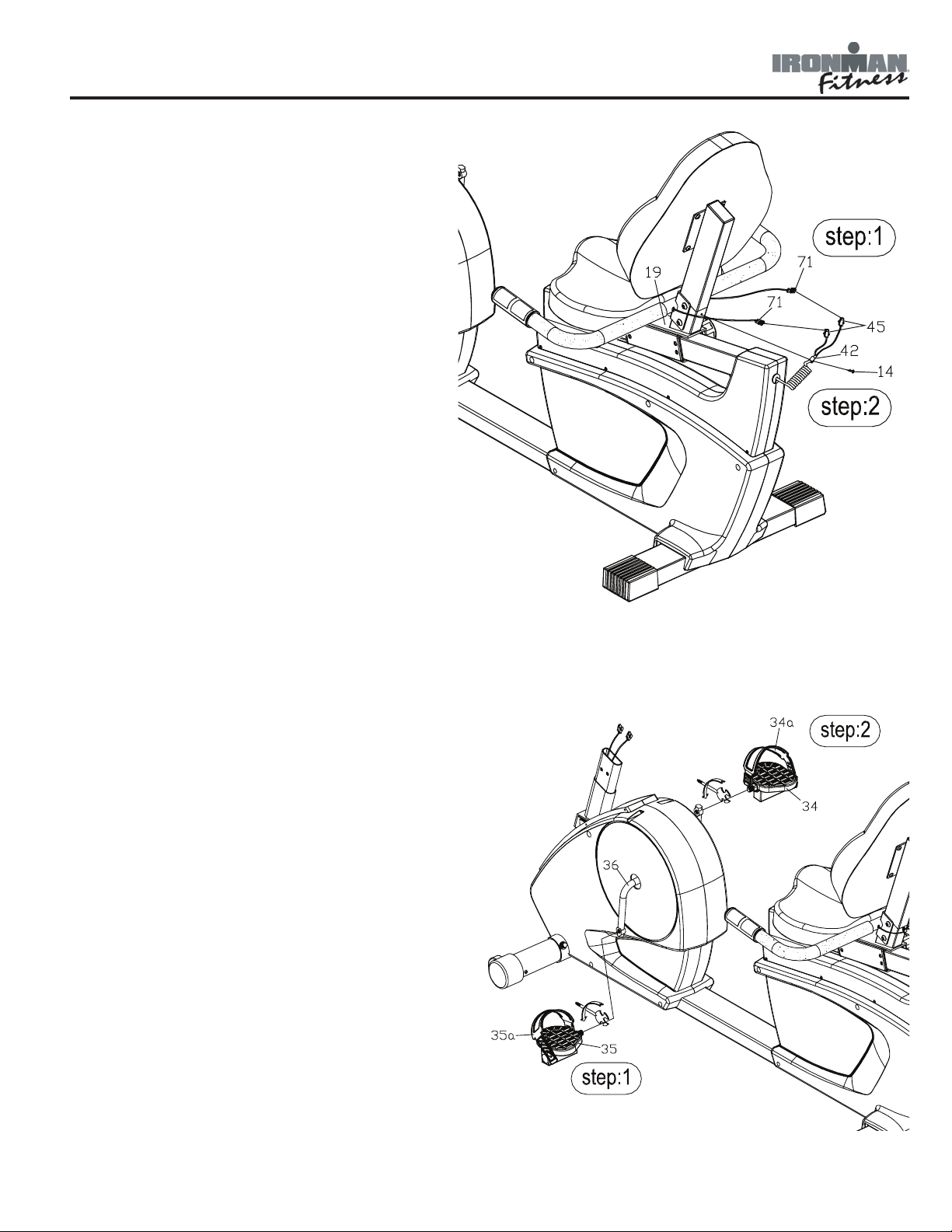
Figure 4
Step 1:
Connect pulse wires (71) to pulse wires
(45).
Step 2:
Secure the pulse wires by attaching the
cable clamp (42) to the seat carriage (19)
using screw (14).
Figure 5
Step 1:
Attach the left pedal (35) to the left
crank. The left pedal is marked with
an "L". Turn the threads on the pedal
counter-clockwise to secure it to the
crank.
Step 2:
Attach the right pedal (34) to the right
crank. The right pedal is marked with
an "R". Turn the threads on the pedal
clockwise to secure it to the crank.
Step 3:
Attach the pedal straps (35a and 34a)
to the appropriate pedal. Each strap is
marked with an "L" or an "R". The side
with 2 holes will go on the clip towards
the inside of the unit.
7
Assembly
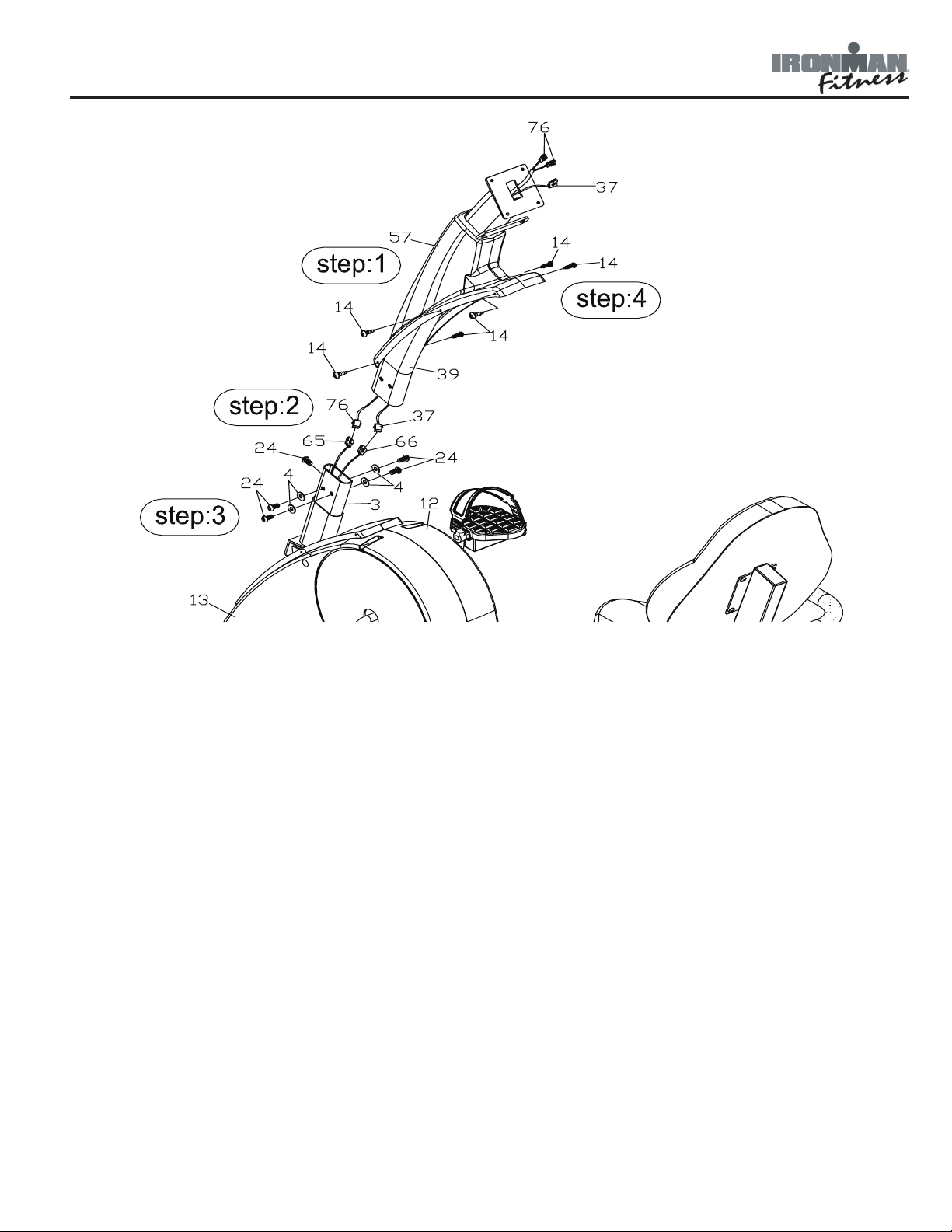
Figure 6
Step 1:
Slide console tube cover (57) up the console tube (39).
Step 2:
Connect pulse wire (66) and wire harness (65) coming from the main frame to pulse wire (76)
and wire harness (37) from the console tube.
Step 3:
Slide the console tube (39) onto main frame (3) and secure using hex head screws (24) and
washers (4). Slide console cover (57) down and secure using screws (14).
Step 4:
Slide the cover all of the way down the console tube. Secure using screws (14).
8
Assembly
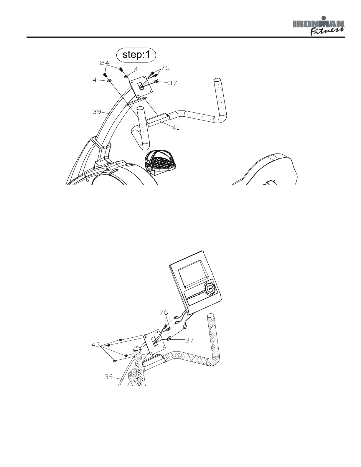
Figure 7
Step 1:
Attach the front handlebar (41) to the console tube (39) using hex head screws (24) and washers (4).
Figure 8
Step 1:
Connect the wires coming from the console to pulse wires (76) and wire harness (37).
Step 2:
Secure the console to the console tube (39) using screws (43).
Note: The screws are already pre-installed into the back of the console.
9
 Loading...