

Page 1

®
VT 275 V6 ENGINE
model year 2005
Page 2

FORWARD
This publication is intended to provide technicians and service personnel with an overview of technical features of the
International
service literature. Consult the latest SERVICE and DIAGNOSTIC manuals before conducting any service or repairs.
®
VT 275 Diesel Engine. The information contained in this publication will supplement information contained in available
Safety Information
s
BBaatttteerriiees
This manual provides general and specific service procedures
and repair methods essential for reliable engine operation and
your safety. Since many variations in procedures, tools, and
service parts are involved, advice for all possible safety
conditions and hazards cannot be stated.
Departure from instructions in this manual or disregard of
warnings and cautions can lead to injury, death, or both, and
damage to the engine or vehicle.
Read safety instructions below before doing service and test
procedures in this manual for the engine or vehicle. See related
application manuals for more information.
Safety Instructions
e
VVeehhiicclle
• Make sure the vehicle is in neutral, the parking brake is set,
and the wheels are bloc
diagnostic procedures on the engine or vehicle.
ked before doing any work or
• Batteries produce highly flammable gas during and after
c
harging.
• Always disconnect the main negative battery cable first.
• Always connect the main negative battery cable last.
• Avoid leaning over batteries.
• Protect your eyes.
• Do not expose batteries to open flames or sparks.
• Do not smoke in workplace.
CCoommpprreesssseedd AAiir
• Limit shop air pressure for blow gun to 207 kPa (30psi).
• Use approved equipment.
• Do not direct air at b
r
ody or clothing.
WWoorrkk AArreea
• Keep area clean, dry and organized.
• K
• Make sure the work area is ventilated and well lit.
• Make sure a First Aid Kit is available.
SSaaffeettyy EEqquuiippmmeennt
• Use correct lifting devices.
• Use saf
PPrrootteeccttiivvee MMeeaassuurrees
• Wear protective glasses and saf
bare feet, sandals, or sneakers).
• Wear appropriate hearing protection.
• Wear correct clothing.
• Do not wear rings, watches, or other jewelry.
• Restrain long hair.
FFiirree pprreevveennttiioon
• Make sure charged fire extinguishers are in the work area.
NNOOTTEE:
ensure that the following fire types can be extinguished.
a
eep tools and parts off the floor.
t
ety blocks and stands.
s
ety shoes (do not work in
n
:
Check the classification of eac
1. Type A - Wood, paper, textiles, and rubbish
2. Type B - Flammable liquids
3. Type C - Electrical equipment
h fire extinguisher to
• Wear safety glasses or goggles.
• Wear hearing protection.
• Use shielding to protect others in the work area.
s
TToooolls
• Make sure all tools are in good condition.
• Make sure all standard electrical tools are grounded.
• Check for frayed power cords before using power tools.
FFlluuiiddss UUnnddeerr PPrreessssuurre
• Use extreme caution when working on systems
under pressure.
• F
ollow approved procedures only.
l
FFuueel
• Do not over fill fuel tank. Over fill creates a fire hazard.
• Do not smoke in the work area.
• Do not refuel the tank when the engine is running.
RReemmoovvaall ooff TToooollss,, PPaarrttss,, aanndd EEqquuiippmmeennt
• Reinstall all safety guards, shields and covers after servicing
the engine.
• Make sure all tools, parts, and service equipment are
removed from the engine and vehicle after all work is done.
e
t
2
International®VT 275 V6 Engine
Page 3

TABLE OF CONTENTS
OVERVIEW . . . . . . . . . . . . . . . . . . . . . . . . . . . . . . . . . . . . . . . . . . . . . . . . . . . .6
COMPONENT LOCATIONS . . . . . . . . . . . . . . . . . . . . . . . . . . . . . . . . . . . . . . . .8
DESIGN FEATURES . . . . . . . . . . . . . . . . . . . . . . . . . . . . . . . . . . . . . . . . . . . .18
ELECTRONIC CONTROL SYSTEM . . . . . . . . . . . . . . . . . . . . . . . . . . . . . . . . . .22
AIR MANAGEMENT SYSTEM . . . . . . . . . . . . . . . . . . . . . . . . . . . . . . . . . . . . .40
FUEL SUPPLY SYSTEM . . . . . . . . . . . . . . . . . . . . . . . . . . . . . . . . . . . . . . . . .48
FUEL MANAGEMENT SYSTEM . . . . . . . . . . . . . . . . . . . . . . . . . . . . . . . . . . . .52
INJECTOR OPERATION . . . . . . . . . . . . . . . . . . . . . . . . . . . . . . . . . . . . . . . . .56
LUBRICATION SYSTEM . . . . . . . . . . . . . . . . . . . . . . . . . . . . . . . . . . . . . . . . .60
COOLING SYSTEM . . . . . . . . . . . . . . . . . . . . . . . . . . . . . . . . . . . . . . . . . . . . .68
UNIQUE REPAIR PROCEDURES . . . . . . . . . . . . . . . . . . . . . . . . . . . . . . . . . . .72
SPECIAL TOOLS . . . . . . . . . . . . . . . . . . . . . . . . . . . . . . . . . . . . . . . . . . . . . . .86
DIAGNOSTIC PROCEDURES . . . . . . . . . . . . . . . . . . . . . . . . . . . . . . . . . . . . . .90
DIAGNOSTIC TROUBLE CODES . . . . . . . . . . . . . . . . . . . . . . . . . . . . . . . . . .100
ENGINE & CHASSIS SCHEMATIC . . . . . . . . . . . . . . . . . . . . . . . . . . . . . . . . .102
POWER DISTRIBUTION CENTER FUSES . . . . . . . . . . . . . . . . . . . . . . . . . . .104
GLOSSARY . . . . . . . . . . . . . . . . . . . . . . . . . . . . . . . . . . . . . . . . . . . . . . . . . .106
INDEX . . . . . . . . . . . . . . . . . . . . . . . . . . . . . . . . . . . . . . . . . . . . . . . . . . . . . .108
International®VT 275 V6 Engine
3
Page 4

4
Page 5

DIRECT INJECTION TURBOCHARGED DIESEL ENGINE
VT 275 FEATURES
• 90° V6
• Offset Crankpins
• Rear Gear Train
• Primary Balancer
• Regulated Two-Stage Turbocharging System
• Four Valves per Cylinder
• Cooled Exhaust Gas Recirculation
• Electro-Hydraulic Generation 2 Fuel Injection System
• Top Mounted Oil and Fuel Filters
International®VT 275 V6 Engine
5
Page 6

VT 275 OVERVIEW
0
50
100
150
200
250
300
350
400
450
500
600
800
1000
1200
1400
1600
1800
2000
2200
2400
2600
2800
3000
3200
3400
3600
0
25
50
75
100
125
150
175
200
225
250
Torque (ft-lb)
Power (HP)
Engine Speed (RPM)
Load (ft-lb)
Power (HP)
Power & Torque Curve
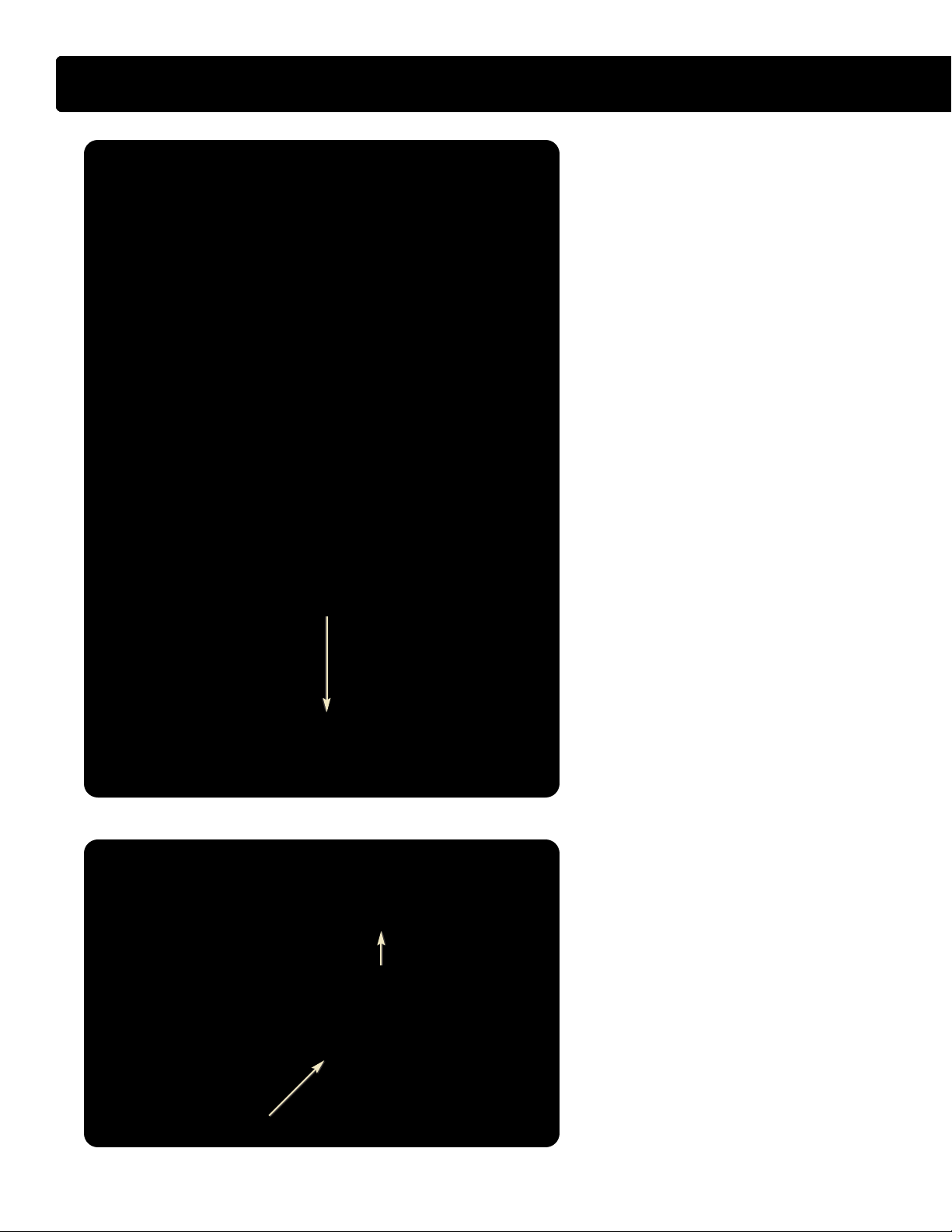
VT 275 ENGINE SPECIFICATIONS
Engine Type . . . . . . . . . . . . . . . . . . . . . . . . . . . . . . . . . . . . . . . . 4-stroke, direct injection diesel
Configuration . . . . . . . . . . . . . . . . . . . . . . . . . . . . V6, pushrod operated four valves / cylinder
Displacement . . . . . . . . . . . . . . . . . . . . . . . . . . . . . . . . . . . . . . . . . . . . . . 275 cu. in. (4.5 liters)
Bore . . . . . . . . . . . . . . . . . . . . . . . . . . . . . . . . . . . . . . . . . . . . . . . . . . . . . . . . . 3.74 in. (95 mm)
Stroke . . . . . . . . . . . . . . . . . . . . . . . . . . . . . . . . . . . . . . . . . . . . . . . . . . . . . 4.134 in. (105 mm)
Compression Ratio . . . . . . . . . . . . . . . . . . . . . . . . . . . . . . . . . . . . . . . . . . . . . . . . . . . . . . 18.0:1
Aspiration . . . . . . . . . . . . . . . . . . . . . . . . . . . . . . . . . Twin turbocharged and charge air cooled
Rated Power . . . . . . . . . . . . . . . . . . . . . . . . . . . . . . . . . . . . . . . . . . . . . . . . 200 hp @ 2700 rpm
Peak Torque . . . . . . . . . . . . . . . . . . . . . . . . . . . . . . . . . . . . . . . . . . . . . . . 440 lb-ft @ 1800 rpm
Engine Rotation, Facing the Flywheel . . . . . . . . . . . . . . . . . . . . . . . . . . . . . Counterclockwise
Injection System . . . . . . . . . . . . . . . . . . . . . . . . . Electro-hydraulic generation 2 fuel injection
Cooling System Capacity (Engine Only) . . . . . . . . . . . . . . . . . . . . . . . . . . . . . . . . . . 11 quarts
Lube System Capacity (Engine Only) . . . . . . 13 quarts with oil filter (14 quarts at overhaul)
Slide Title Goes Here
Horsepower and Torque
• The VT 275 engine is offered with only one
horsepower and torque rating for the 2005
model year. The engine creates 200
horsepower at 2700 rpm and 440 lb-ft of
torque at 1800 rpm. The engine has a
high idle speed of 2775 rpm with
automatic transmission. The engine idle
speed is set at 700 rpm and is not adjustable.
6
International®VT 275 V6 Engine
Page 7
Engine Serial Number
2
4
6
5
3
1
Front
L
R
• The Engine Serial Number (ESN) for the
VT 275 is located on a machined surface
at the left rear corner of the crankcase just
below the cylinder head.
• The ESN identifies the engine family, the
build location, and the sequential
build number.
• Engine Serial Number Example
4.5HM2Y0135617
4.5 = Engine displacement
H = Diesel, T
M2 = Motor Truck
Y = Huntsville
0135617 = Build Sequence
urbocharged
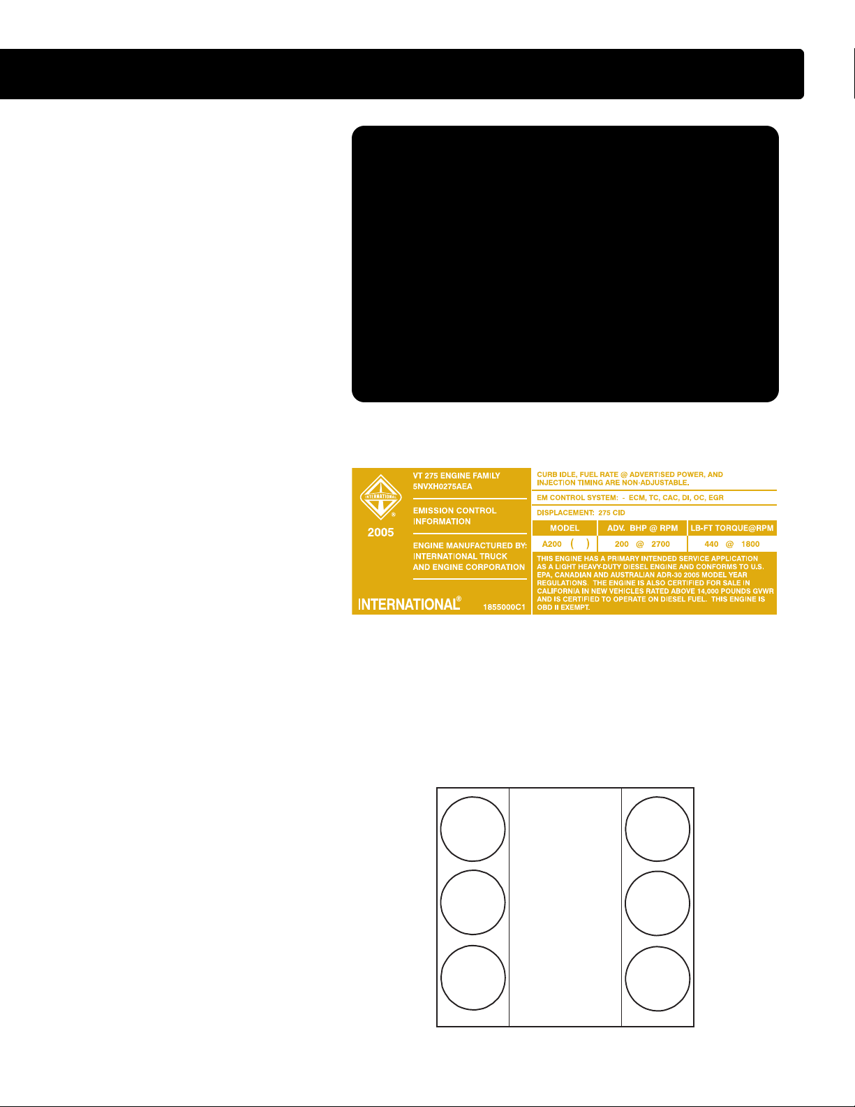
Emissions Label
• The Environmental Protection Agency
(EPA) emissions label is on top of the
breather, toward the front, on the left valve
cover. The label includes the following:
VT 275 OVERVIEW
-Advertised horsepower rating
-Engine model code
-Service application
-Emission family and control system
-Year the engine was certified to meet EPA
emission standards.
Cylinder Numbering
• The cylinders on the VT 275 are numbered
from the front of the right bank 1, 3, 5 and
from the front of the left bank 2, 4 and 6.
• The engine firing order is 1-2-5-6-3-4
International®VT 275 V6 Engine
7
Page 8

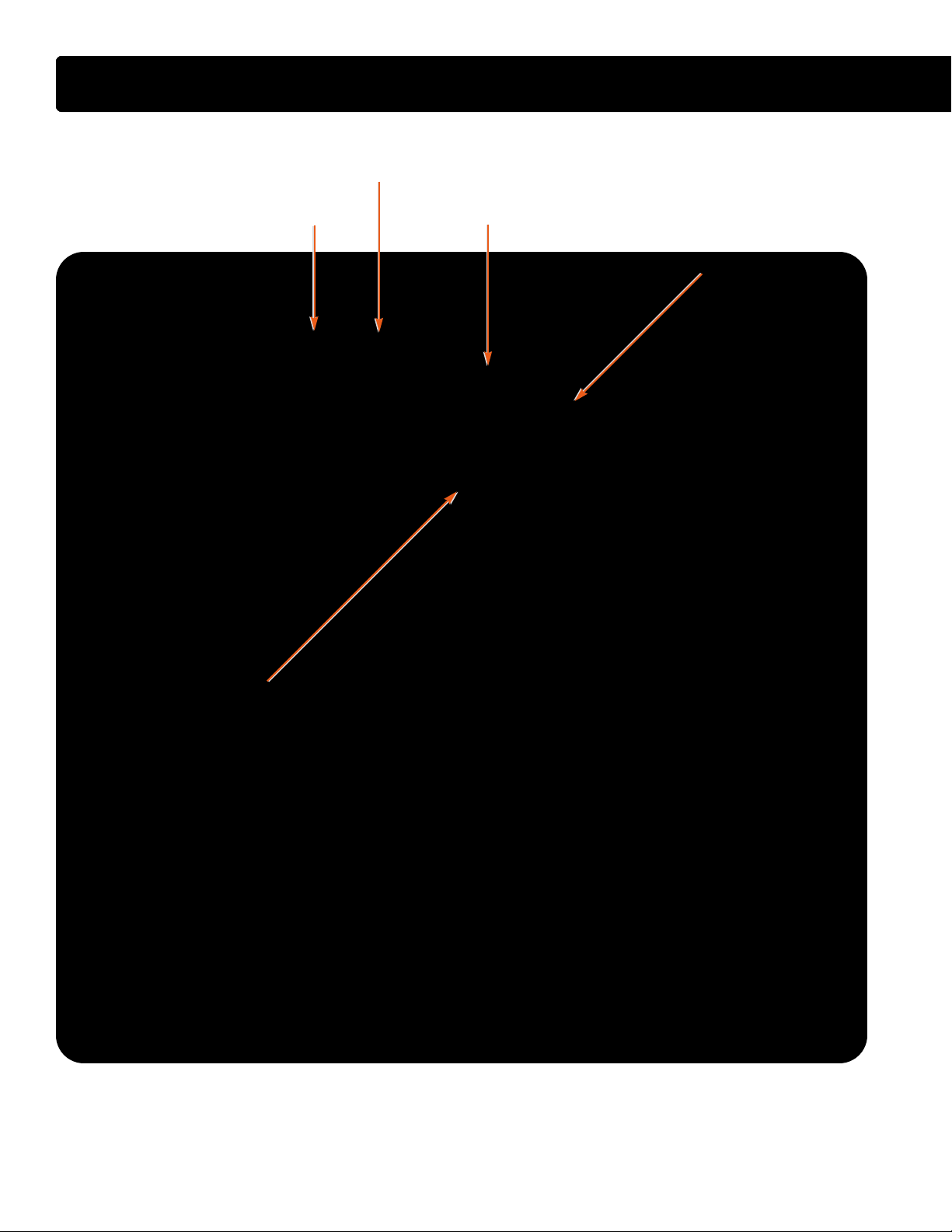
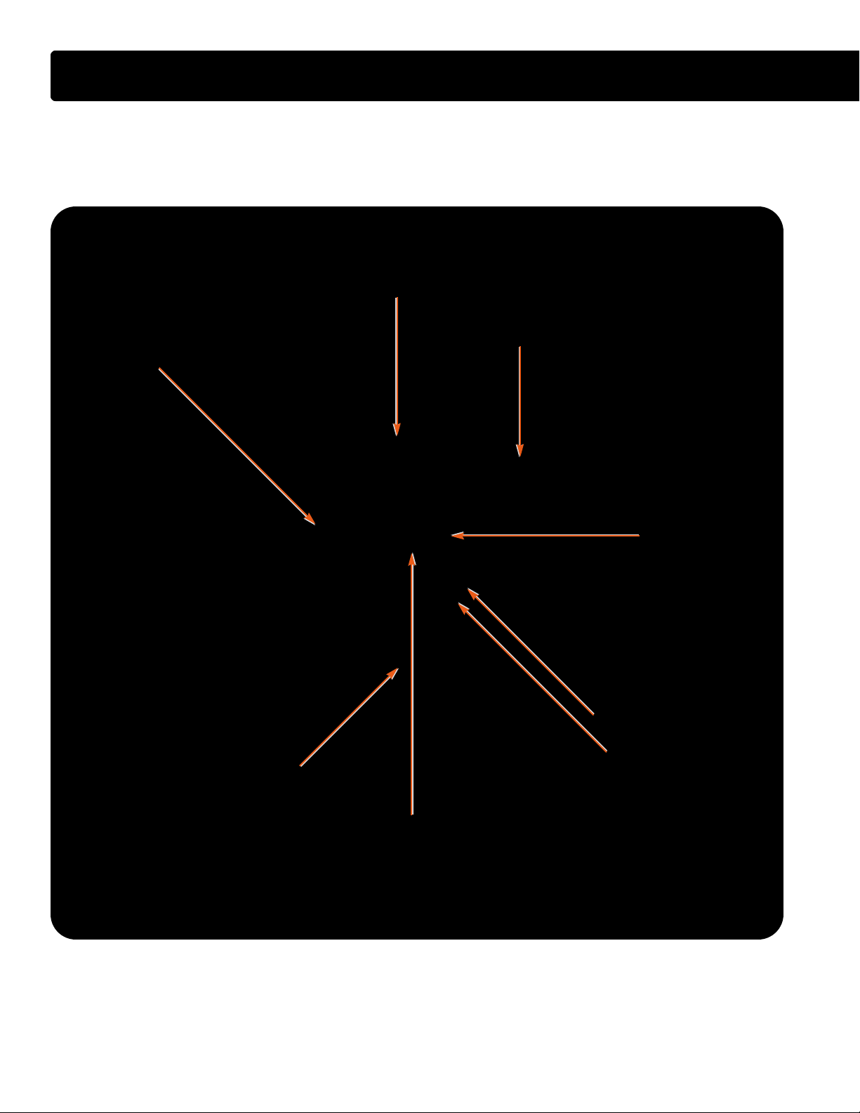
COMPONENT LOCATIONS - FRONT OF ENGINE
AAIIRR IINNLLEETT HHEEAATTEERR
HHEEAATTEERR SSUUPPPPLLYY TTUUBBEE
HHEEAATTEERR SSUUPPPPLLYY TTUUBBEE
SSMMOOOOTTHH IIDDLLEERR PPUULLLLEEYY
SSMMOOOOTTHH IIDDLLEERR PPUULLLLEEYY
AAIIRR IINNLLEETT HHEEAATTEERR
AAIIRR IINNLLEETT
AAIIRR IINNLLEETT
IINNTTAAKKEE MMAANNIIFFOOLLDD
IINNTTAAKKEE MMAANNIIFFOOLLDD
BBAANNJJOO BBOOLLTT WWIITTHH
BBAANNJJOO BBOOLLTT WWIITTHH
CCHHEECCKK VVAALLVVEE
CCHHEECCKK VVAALLVVEE
FFUUEELL TTUUBBEE TTOO RRIIGGHHTT BBAANNKK
FFUUEELL TTUUBBEE TTOO RRIIGGHHTT BBAANNKK
MMAATT SSEENNSSOORR
MMAATT SSEENNSSOORR
PPOOWWEERR SSTTEEEERRIINNGG
PPOOWWEERR SSTTEEEERRIINNGG
PPUUMMPP BBRRAACCKKEETT
PPUUMMPP BBRRAACCKKEETT
BBEELLTT TTEENNSSIIOONNEERR
BBEELLTT TTEENNSSIIOONNEERR
OOIILL PPUUMMPP CCOOVVEERR
OOIILL PPUUMMPP CCOOVVEERR
8
International®VT 275 V6 Engine
Page 9

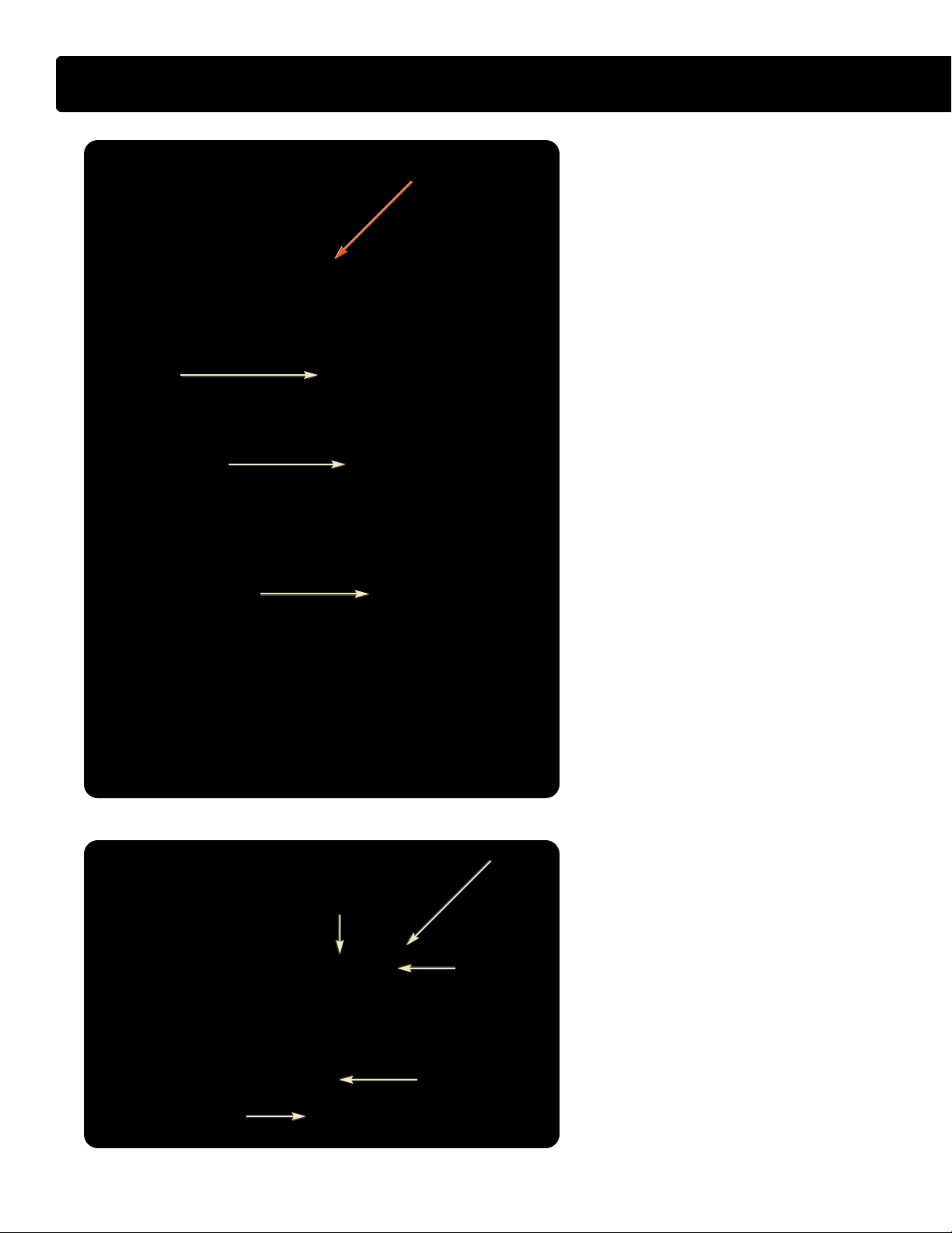
COMPONENT LOCATIONS - LEFT FRONT OF ENGINE
GGRROOOOVVEEDD IIDDLLEERR PPUULLLLEEYY
GGRROOOOVVEEDD IIDDLLEERR PPUULLLLEEYY
BBRREEAATTHHEERR
BBRREEAATTHHEERR
SSMMOOOOTTHH IIDDLLEERR PPUULLLLEEYY
SSMMOOOOTTHH IIDDLLEERR PPUULLLLEEYY
RREETTUURRNN TTUUBBEE
RREETTUURRNN TTUUBBEE
CCOOOOLLAANNTT OOUUTTLLEETT
CCOOOOLLAANNTT OOUUTTLLEETT
HHEEAATTEERR
HHEEAATTEERR
International®VT 275 V6 Engine
9
Page 10

COMPONENT LOCATIONS - LEFT SIDE OF ENGINE
AAIIRR IINNLLEETT DDUUCCTT
AAIIRR IINNLLEETT DDUUCCTT
OOIILL LLEEVVEELL
OOIILL LLEEVVEELL
LLEEFFTT BBAANNKK
LLEEFFTT BBAANNKK
GGLLOOWW PPLLUUGGSS
GGLLOOWW PPLLUUGGSS
GGAAUUGGEE
GGAAUUGGEE
10
CCMMPP SSEENNSSOORR
CCMMPP SSEENNSSOORR
FFUUEELL RREETTUURRNN TTOO TTAANNKK
FFUUEELL RREETTUURRNN TTOO TTAANNKK
International®VT 275 V6 Engine
SSUUPPPPLLYY FFRROOMM FFUUEELL PPUUMMPP
SSUUPPPPLLYY FFRROOMM FFUUEELL PPUUMMPP
AANNDD PPRRIIMMAARRYY FFIILLTTEERR
AANNDD PPRRIIMMAARRYY FFIILLTTEERR
Page 11

IIPPRR AANNDD
IIPPRR AANNDD
HHEEAATT SSHHIIEELLDD
HHEEAATT SSHHIIEELLDD
COMPONENT LOCATIONS - LEFT REAR OF ENGINE
LLIIFFTTIINNGG EEYYEESS
LLIIFFTTIINNGG EEYYEESS
LLEEFFTT BBAANNKK
LLEEFFTT BBAANNKK
EEXXHHAAUUSSTT MMAANNIIFFOOLLDD
EEXXHHAAUUSSTT MMAANNIIFFOOLLDD
RREEAARR CCOOVVEERR
RREEAARR CCOOVVEERR
International®VT 275 V6 Engine
11
Page 12
COMPONENT LOCATIONS - REAR OF ENGINE
OOIILL FFIILLTTEERR HHOOUUSSIINNGG
OOIILL FFIILLTTEERR HHOOUUSSIINNGG
FFUUEELL FFIILLTTEERR HHOOUUSSIINNGG
FFUUEELL FFIILLTTEERR HHOOUUSSIINNGG
TTUURRBBIINNEE OOUUTTLLEETT
TTUURRBBIINNEE OOUUTTLLEETT
EEXXHHAAUUSSTT TTUUBBEE AASSSSEEMMBBLLYY
EEXXHHAAUUSSTT TTUUBBEE AASSSSEEMMBBLLYY
HHIIGGHH PPRREESSSSUURREE PPUUMMPP CCOOVVEERR
HHIIGGHH PPRREESSSSUURREE PPUUMMPP CCOOVVEERR
12
International®VT 275 V6 Engine
Page 13

COMPONENT LOCATIONS - RIGHT REAR OF ENGINE
HHIIGGHH PPRREESSSSUURREE CCOOMMPPRREESSSSOORR HHOOUUSSIINNGG
HHIIGGHH PPRREESSSSUURREE CCOOMMPPRREESSSSOORR HHOOUUSSIINNGG
CCOOOOLLAANNTT
CCOOOOLLAANNTT
HHEEAATTEERR
HHEEAATTEERR
UUPPPPEERR OOIILL PPAANN
UUPPPPEERR OOIILL PPAANN
LLOOWWEERR OOIILL PPAANN
LLOOWWEERR OOIILL PPAANN
International®VT 275 V6 Engine
13
Page 14

COMPONENT LOCATIONS - RIGHT SIDE OF ENGINE
OOUUTTLLEETT TTOO CCHHAARRGGEE AAIIRR CCOOOOLLEERR
OOUUTTLLEETT TTOO CCHHAARRGGEE AAIIRR CCOOOOLLEERR
TTUURRBBOOCCHHAARRGGEERR CCRROOSSSSOOVVEERR TTUUBBEE
TTUURRBBOOCCHHAARRGGEERR CCRROOSSSSOOVVEERR TTUUBBEE
IICCPP
IICCPP
SSEENNSSOORR
SSEENNSSOORR
RRIIGGHHTT BBAANNKK
RRIIGGHHTT BBAANNKK
GGLLOOWW PPLLUUGGSS
GGLLOOWW PPLLUUGGSS
CCRRAANNKKCCAASSEE
CCRRAANNKKCCAASSEE
LLOOWWEERR
LLOOWWEERR
CCRRAANNKKCCAASSEE
CCRRAANNKKCCAASSEE
CCKKPP SSEENNSSOORR
CCKKPP SSEENNSSOORR
14
International®VT 275 V6 Engine
Page 15

COMPONENT LOCATIONS - RIGHT FRONT OF ENGINE
PPNNEEUUMMAATTIICC AACCTTUUAATTOORR
PPNNEEUUMMAATTIICC AACCTTUUAATTOORR
BBOOOOSSTT CCOONNTTRROOLL SSOOLLEENNOOIIDD
BBOOOOSSTT CCOONNTTRROOLL SSOOLLEENNOOIIDD
MMAAPP
MMAAPP
SSEENNSSOORR
SSEENNSSOORR
EECCTT
EECCTT
SSEENNSSOORR
SSEENNSSOORR
WWAATTEERR PPUUMMPP
WWAATTEERR PPUUMMPP
PPUULLLLEEYY
PPUULLLLEEYY
AANNDD FFAANN DDRRIIVVEE
AANNDD FFAANN DDRRIIVVEE
International®VT 275 V6 Engine
15
Page 16
COMPONENT LOCATIONS - TOP OF ENGINE WITHOUT HARNESS
HHIIGGHH PPRREESSSSUURREE PPUUMMPP
HHIIGGHH PPRREESSSSUURREE PPUUMMPP
IINNJJEECCTTOORR CCOONNNNEECCTTOORRSS
IINNJJEECCTTOORR CCOONNNNEECCTTOORRSS
HHIIGGHH PPRREESSSSUURREE TTUURRBBIINNEE HHOOUUSSIINNGG
HHIIGGHH PPRREESSSSUURREE TTUURRBBIINNEE HHOOUUSSIINNGG
EEGGRR VVAALLVVEE
EEGGRR VVAALLVVEE
LLOOWW PPRREESSSSUURREE TTUURRBBOO CCOOMMPPRREESSSSOORR HHOOUUSSIINNGG
LLOOWW PPRREESSSSUURREE TTUURRBBOO CCOOMMPPRREESSSSOORR HHOOUUSSIINNGG
TTUURRBBOOCCHHAARRGGEERR
TTUURRBBOOCCHHAARRGGEERR
OOIILL SSUUPPPPLLYY LLIINNEE
OOIILL SSUUPPPPLLYY LLIINNEE
EEOOPP SSWWIITTCCHH
EEOOPP SSWWIITTCCHH
EEOOTT SSEENNSSOORR
EEOOTT SSEENNSSOORR
16
International®VT 275 V6 Engine
Page 17

COMPONENT LOCATIONS - TOP OF ENGINE WITH HARNESS
MMAAFF SSEENNSSOORR CCOONNNNEECCTTOORR
MMAAFF SSEENNSSOORR CCOONNNNEECCTTOORR
((SSEENNSSOORR NNOOTT SSHHOOWWNN))
((SSEENNSSOORR NNOOTT SSHHOOWWNN))
IINNJJEECCTTOORR HHAARRNNEESSSS CCOONNNNEECCTTOORR
IINNJJEECCTTOORR HHAARRNNEESSSS CCOONNNNEECCTTOORR
HHAARRNNEESSSS TTOO
HHAARRNNEESSSS TTOO
CCHHAASSSSIISS MMOOUUNNTTEEDD
CCHHAASSSSIISS MMOOUUNNTTEEDD
EECCMM//IIDDMM
EECCMM//IIDDMM
BBOOOOSSTT CCOONNTTRROOLL SSOOLLEENNOOIIDD
BBOOOOSSTT CCOONNTTRROOLL SSOOLLEENNOOIIDD
AALLTTEERRNNAATTOORR FFUUSSIIBBLLEE LLIINNKKSS
AALLTTEERRNNAATTOORR FFUUSSIIBBLLEE LLIINNKKSS
((AALLTTEERRNNAATTOORR NNOOTT SSHHOOWWNN))
((AALLTTEERRNNAATTOORR NNOOTT SSHHOOWWNN))
International®VT 275 V6 Engine
17
Page 18

VT 275 DESIGN FEATURES
RROOCCKKEERR AARRMM CCAARRRRIIEERR
RROOCCKKEERR AARRMM CCAARRRRIIEERR
RROOCCKKEERR AARRMM
RROOCCKKEERR AARRMM
RROOCCKKEERR AARRMM FFUULLCCRRUUMM
RROOCCKKEERR AARRMM FFUULLCCRRUUMM
Cylinder Head Assembly
• The VT 275 has an aluminum rocker arm
carrier for each cylinder head. The carrier
holds the fulcrum plates and the attached
rocker arms and can be removed as an
assembly from the cylinder head without
removing the rocker arms.
• Each rocker arm pivots on a steel ball
located by detents in the fulcrum plate.
Four head bolts on each cylinder head
pass through the two single and two dual
fulcrum plates serving to clamp the plates
to the carrier.
• The cylinder head is sealed to the
crankcase deck surface with a shim type
gasket that must be replaced if any of the
head bolts are removed. The 14mm head
bolts are torque to yield and cannot
be reused.
• The carrier is sealed to the cylinder head
with a push-in-place gasket. The cylinder
head and carrier are clamped to the
crankcase with eight 14mm bolts. Six
additional 8mm bolts around the perimeter
clamp the carrier to the cylinder head and
four additional 8mm bolts serve to clamp
the top of the head to the crankcase. Two
hollow dowels in the cylinder head are
used to align the rocker arm carrier to the
cylinder head.
IINNJJEECCTTOORR
PPAASSSS--
TTHHRROOUUGGHH
DDUUAALL FFUULLCCRRUUMM PPLLAATTEE
HHEEAADD BBOOLLTTSS
SSIINNGGLLEE
FFUULLCCRRUUMM
PPLLAATTEE
18
88mmmm FFUULLCCRRUUMM BBOOLLTT
GGLLOOWW PPLLUUGG
CCOONNNNEECCTTOORR OOPPEENNIINNGG
International®VT 275 V6 Engine
Rocker Arm Carrier
• The rocker arm carrier serves as an
attachment point for the fulcrum plates and
the rocker arms. In addition to the head
bolts, single fulcrum plates are attached to
the rocker arm carrier with one 8mm bolt.
The dual fulcrum plates are attached with
two 8mm bolts. The fulcrum plates are
marked with E and I as assembly aids to
show the valves they support. The E and I
must be visible after assembly to the head.
In addition, the carrier provides a passage
for each snap-in-place injector passthrough and the push-in-place glow
plug connectors.
Page 19

VT 275 DESIGN FEATURES
Crankcase Assembly
• The VT 275 has four main bearings but
replaces the traditional individual main
bearing caps with a one-piece lower
crankcase assembly. The lower crankcase
is made of cast iron and is stronger than
the individual caps. The lower crankcase is
attached to the crankcase with sixteen
14mm main bearing bolts of two lengths
with the shorter bolts to the outside. Three
additional 8mm bolts are used on each
side at the perimeter. The lower crankcase
is sealed to the crankcase with two pushin-place seals.
Crankcase and Oil Pan
• The upper oil pan bolts to the lower
crankcase and is sealed with a full
perimeter push-in-place gasket. The lower
sheet metal oil pan is sealed to the upper
cast aluminum oil pan with a full perimeter
push-in-place gasket. The upper oil pan is
wider than the crankcase and allows for
greater oil pan capacity without
increased depth.
1144mmmm MMAAIINN BBEEAARRIINNGG BBOOLLTTSS
1144mmmm MMAAIINN BBEEAARRIINNGG BBOOLLTTSS
LLOOWWEERR OOIILL PPAANN
LLOOWWEERR OOIILL PPAANN
OOIILL PPIICCKK--UUPP TTUUBBEE
OOIILL PPIICCKK--UUPP TTUUBBEE
LLOOWWEERR CCRRAANNKKCCAASSEE
LLOOWWEERR CCRRAANNKKCCAASSEE
88mmmm BBOOLLTTSS
UUPPPPEERR OOIILL PPAANN
UUPPPPEERR OOIILL PPAANN
• The oil pickup is sealed to the upper oil
pan with an O-ring and attached with two
6mm bolts. Oil pulled through the oil
pickup tube passes through a passage
cast in the upper oil pan to the lower
crankcase. The lower crankcase has a
machined passage that takes oil to a front
cover passage that leads to the oil pump.
Openings in the upper oil pan allow oil to
return to the pan during engine operation
but also serve to keep oil in the pan away
from the rotating crankshaft.
CCRRAANNKKSSHHAAFFTT
CCRRAANNKKSSHHAAFFTT
UUPPPPEERR
UUPPPPEERR
CCRRAANNKKCCAASSEE
CCRRAANNKKCCAASSEE
LLOOWWEERR
LLOOWWEERR
CCRRAANNKKCCAASSEE
CCRRAANNKKCCAASSEE
International®VT 275 V6 Engine
19
Page 20
VT 275 DESIGN FEATURES
CCAAMMSSHHAAFFTT
GGEEAARR
BBAALLAANNCCEERR SSHHAAFFTT
GGEEAARR
CCRRAANNKKSSHHAAFFTT FFLLAANNGGEE
AANNDD GGEEAARR
HHIIGGHH PPRREESSSSUURREE OOIILL
HHIIGGHH PPRREESSSSUURREE OOIILL
PPUUMMPP GGEEAARR
PPUUMMPP GGEEAARR
Rear Gear Train
• The VT 275 gear train is located at the rear
of the engine. The crankshaft gear is a
press fit on the crankshaft and drives the
camshaft gear directly. The crankshaft
flange with integral gear is pressed on the
end of the crankshaft then clamped with
six 12mm bolts. The camshaft gear must
be timed to the crankshaft gear during
assembly to maintain the correct relationship.
• The rear flange gear drives the primary
balance shaft gear at a one-to-one ratio.
The balance shaft runs through the hollow
camshaft to the front of the crankcase and
has the balance shaft counterweight
bolted to the front of the shaft. The flange
gear and balance shaft gear must be timed
to maintain the correct relationship
between the balance shaft counterweight
and the crankshaft.
• The high-pressure oil pump is located in
the Vee of the engine and is driven directly
off the camshaft gear. The oil pump gear
does not require timing.
CCRRAANNKKSSHHAAFFTT
FFLLAANNGGEE && GGEEAARR
TTIIMMIINNGG PPIINN HHOOLLEE
CCAAMMSSHHAAFFTT
BBAALLAANNCCEERR
SSHHAAFFTT GGEEAARR
TTIIMMIINNGG GGEEAARR
DDOOTTSS
GGEEAARR
• Note: The crankshaft gear that drives the
camshaft is located behind the flange gear
Gear Timing
• The camshaft and balance shaft must be
timed to the crankshaft for proper engine
operation. During reassembly a timing pin
that aligns the camshaft gear and the
balance shaft gear is placed through the
gears and into a hole machined in the
crankcase, then the crankshaft is installed
while aligning the balance shaft and flange
gear dots. If only the balance shaft is out of
the engine, the shaft can be installed while
aligning the balance shaft gear and flange
gear dots.
.
20
International®VT 275 V6 Engine
Page 21

Offset Crankpins
• The 4-stroke engine requires 720° of
crankshaft rotation to complete all four
strokes of the cycle. In a multi-cylinder
engine dividing the 720 degrees by the
number of cylinders will equal the ideal
crankshaft rotation between combustion
events in the firing order. The VT 275
achieves equal spacing of the combustion
events by splitting the crankpins and
staggering the individual journals 30º.
Balance Shaft Timing
• The crankshaft counterweight, flywheel,
and damper are used to offset the rotating
and reciprocating forces developed in the
90° V6 engine, but these components
alone will not offset the couple imbalance.
Couple imbalance is created when two or
more forces act on the crankshaft at
different points along its length. Couple
imbalance, if not offset, results in pitch and
yaw forces on the engine that are felt by
the vehicle occupants as a vibration.
CCOOUUNNTTEERR WWEEIIGGHHTTEEDD
CCOOUUNNTTEERR WWEEIIGGHHTTEEDD
BBAALLAANNCCEERR SSHHAAFFTT GGEEAARR
BBAALLAANNCCEERR SSHHAAFFTT GGEEAARR
VT 275 DESIGN FEATURES
##44 CCRRAANNKKPPIINN
##33 CCRRAANNKKPPIINN
BBAALLAANNCCEERR SSHHAAFFTT
BBAALLAANNCCEERR SSHHAAFFTT
CCOOUUNNTTEERR WWEEIIGGHHTT
CCOOUUNNTTEERR WWEEIIGGHHTT
• Couple imbalance forces in the engine are
offset by the balance shaft forces as it
rotates at crankshaft speed but in the
opposite direction.
International®VT 275 V6 Engine
21
Page 22

ECT
ECM
CKP
IDM
BAP
EOP
MAPICPIPR
EGR DRIVE
MODULE
BCS MAF / IAT
EOTMAT APS / IVS
CMP
®
ELECTRONIC CONTROL
SYSTEM
• ECM and IDM control system
• Dual magnetic pick-up timing sensors
• Electric motor driven EGR valve
• ECM boost control
System Features
• The VT 275 engine uses the Diamond
Logic™ II Control System. The electronic
control system features an Engine
Control Module (ECM) and an Injector
Drive Module (IDM).
• The Exhaust Gas Recirculation (EGR)
valve is positioned by an ECM controlled
electric stepper motor. The system uses
an EGR drive module to communicate
commands from the ECM to the
EGR valve.
• VT 275 engines use two magnetic pickup sensors to determine crankshaft
speed and position and camshaft
position. Magnetic pick-up sensors
feature high reliability and accuracy.
22
• The VT 275 engine uses a twin
turbocharger with ECM boost control.
International®VT 275 V6 Engine
Page 23

ELECTRONIC CONTROL SYSTEM
ECM
• The ECM uses sensor inputs to control the
Injection Pressure Regulator (IPR), the
EGR valve, the boost control solenoid, the
glow plug relay and the inlet air heater
relay. The ECM also shares sensor data
with the IDM over communication links
between the two modules.
• The IDM is mounted on brackets cast into
the ECM. The ECM and IDM are then
mounted with vibration isolator grommets
to the control module assembly bracket.
The bracket is bolted to the truck's frame
directly behind the passenger side of the
cab and serves as the mounting point for
the inlet air heater relay, the glow plug relay,
and the Power Distribution Center (PDC).
IINNLLEETT AAIIRR
IINNLLEETT AAIIRR
HHEEAATTEERR RREELLAAYY
HHEEAATTEERR RREELLAAYY
CCOONNTTRROOLL MMOODDUULLEE
CCOONNTTRROOLL MMOODDUULLEE
AASSSSEEMMBBLLYY BBRRAACCKKEETT
AASSSSEEMMBBLLYY BBRRAACCKKEETT
EECCMM
EECCMM
GGLLOOWW PPLLUUGG RREELLAAYY
GGLLOOWW PPLLUUGG RREELLAAYY
IDM
• The Injector Drive Module (IDM) receives
sensor information from the ECM over
three communication links: the CAN 2 link,
the CMPO circuit, and the CKPO circuit.
The IDM uses this information to calculate
injection timing and duration. The IDM
controls injector operation through 48-volt
signals to the twin injector coils.
• The ECM has four connectors. The
connectors are called X1 through X4 with
ECM X1 being the top ECM connector as
mounted on the truck. The IDM has three
connectors with IDM X1 being the top
connector as mounted on the truck. The
ECM X1 and X2 connectors are for engine
sensor inputs and X3 and X4 are for
chassis inputs. The IDM X1 and X2
connectors are for injector operation and
X3 is for chassis inputs and
communication between the ECM and IDM.
IIDDMM XX11
IIDDMM XX11
IIDDMM XX22
IIDDMM XX22
IIDDMM XX33
IIDDMM XX33
IIDDMM
IIDDMM
EECCMM XX11
EECCMM XX11
EECCMM XX22
EECCMM XX22
EECCMM XX33
EECCMM XX33
EECCMM XX44
EECCMM XX44
International®VT 275 V6 Engine
23
Page 24
ELECTRONIC CONTROL SYSTEM
EGR Drive Module
• The EGR Drive Module is mounted below
the de-aeration tank. The module receives
the desired EGR valve position from the
ECM over the engine CAN 2 link. The
module then sends a series of voltage and
ground signals to the Motor U, V, and W
terminals of the EGR valve. The voltage
signals are Pulse Width Modulated (PWM)
to control current flow to the motor field coils.
• The module receives battery voltage and
ground through the 12-way engine-tochassis connector. The module supplies a
reference voltage to three position sensors
within the EGR valve. The drive module
uses the sensor signals to determine the
percent of valve opening.
EEGGRR DDRRIIVVEE MMOODDUULLEE
IINNLLEETT AAIIRR HHEEAATTEERR
IINNTTAAKKEE MMAANNIIFFOOLLDD
Inlet Air Heater Element
• The Inlet Air Heater element is located in
the lower side of the intake manifold and
projects through the manifold and into the
inlet air stream.
• The element warms the incoming air to aid
cold start and reduce emissions during
warm-up. The ECM turns the inlet air
heater on for a predetermined amount of
time, based on engine oil temperature,
intake air temperature, and barometric air
pressure. The inlet air heater can remain on
while the engine is running to reduce white
smoke during engine warm-up.
24
International®VT 275 V6 Engine
Page 25

Inlet Air Heater Relay
• The Inlet Air Heater (IAH) element is used
to improve cold start operation, reduce
emissions and white smoke, and improve
engine warm-up. The relay is mounted next
to the Power Distribution Center and is the
taller of the two relays. The IAH relay
receives battery power from the starter
power-feed terminal and the normally open
terminal connects to the element through
the harness. One end of the relay coil is
grounded through the engine 12-way
connector. The relay closes when the coil
receives voltage from the ECM.
AAIIRR HHEEAATTEERR RREELLAAYY
AAIIRR HHEEAATTEERR RREELLAAYY
ELECTRONIC CONTROL SYSTEM
Glow Plug Relay
• Glow plugs are used to improve cold
engine starting. Glow plug operation is
controlled by the ECM through the glow
plug relay. The glow plug relay is mounted
next to the Power Distribution Center and
is the shorter of the two relays. The relay
common terminal is connected by jumper
to the common terminal of the Inlet Air
Heater relay. The normally open terminal
connects to the glow plug harness. One
end of the relay coil is grounded through
the engine 12-way connector. The relay is
closed when the other end of the coil
receives voltage from the ECM.
Injection Pressure Regulator (IPR) Valve
• The IPR mounts to the high-pressure pump
and controls the amount of oil allowed to
drain from the high-pressure system.
When the ECM increases the IPR signal
duty cycle, the valve blocks the oil’s path to
drain and pressure rises. When the ECM
reduces the duty cycle, a larger volume of
oil is allowed to drain from the system and
pressure is reduced. The valve contains a
pressure relief valve for the system that
opens if system pressure reaches 4500
psi. The IPR is protected by a heat shield
that must be reinstalled after servicing.
GGLLOOWW PPLLUUGG RREELLAAYY
GGLLOOWW PPLLUUGG RREELLAAYY
IIPPRR
IIPPRR
SSWWIIVVEELL CCOONNNNEECCTTOORR
SSWWIIVVEELL CCOONNNNEECCTTOORR
International®VT 275 V6 Engine
25
Page 26
ELECTRONIC CONTROL SYSTEM
NNOOTT UUSSEEDD
NNOOTT UUSSEEDD
GGRREEEENN HHOOSSEE TTOO
GGRREEEENN HHOOSSEE TTOO
AAIIRR IINNLLEETT DDUUCCTT
AAIIRR IINNLLEETT DDUUCCTT
BBLLAACCKK HHOOSSEE TTOO IINNTTAAKKEE
BBLLAACCKK HHOOSSEE TTOO IINNTTAAKKEE
MMAANNIIFFOOLLDD EELLBBOOWW
MMAANNIIFFOOLLDD EELLBBOOWW
BBOOOOSSTT CCOONNTTRROOLL SSOOLLEENNOOIIDD
BBOOOOSSTT CCOONNTTRROOLL SSOOLLEENNOOIIDD
EEGGRR VVAALLVVEE
EEGGRR VVAALLVVEE
EEXXHHAAUUSSTT IINNLLEETT
EEXXHHAAUUSSTT IINNLLEETT
EEXXHHAAUUSSTT OOUUTTLLEETT
EEXXHHAAUUSSTT OOUUTTLLEETT
PPOOPPPPEETTSS
PPOOPPPPEETTSS
OO--RRIINNGGSS
EEXXHHAAUUSSTT
EEXXHHAAUUSSTT
OOUUTTLLEETT
OOUUTTLLEETT
OO--RRIINNGGSS
Boost Control Solenoid
• The turbocharger boost control solenoid
valve is controlled by the ECM. When
the ECM signal to the Boost Control
solenoid is high, the valve opens,
allowing pressure in the pneumatic
actuator to vent into the turbo inlet duct.
When the ECM signal is low, the valve
closes, and pressure to the actuator
equals boost pressure in the intake manifold.
Exhaust Gas Recirculation (EGR) Valve
• The EGR valve is used to control the
percent of exhaust gas in the intake
charge. The EGR valve consists of circuit
board mounted position sensors, field
coils surrounding an armature, and the
valve group. The valve group has two
poppet valves mounted to a common
stem. When the drive module provides
voltage and ground to the field coils in the
proper sequence, stepped armature
rotation occurs. A threaded rod engaged
in the center of the rotating armature
pushes or pulls against the spring
loaded valve stem to force the valve to
open or close.
26
MMAAFF // IIAATT
MMAAFF // IIAATT
55--PPIINN
55--PPIINN
CCOONNNNEECCTTOORR
CCOONNNNEECCTTOORR
MMAAFF
MMAAFF
International®VT 275 V6 Engine
Mass Air Flow (MAF) Sensor
• The Mass Air Flow (MAF) sensor is
mounted with ductwork between the
turbocharger inlet and the air filter element.
The sensor applies voltage to a low
resistance thermistor exposed to the fresh
air portion of the intake charge. The MAF
sensor circuitry measures the increase in
voltage required to offset the cooling
effect of the air flow over the thermistor.
This voltage is then converted into a
variable frequency that is sent to the ECM.
The MAF value can be read with
MasterDiagnostics
®
software in lb./min.
Page 27

ELECTRONIC CONTROL SYSTEM
ECM
BATT ERY
200 A F4
F-46
TO IDM RELAY
TO
ENGINE
INLINE
12-WAY
F41
F-12
R
PDC
1
STAR TER
MOTOR
RELAY
KEY SWITCH
PDC#
F4
F12
F41
F46
R
Device
30A...IDM/ECM
20A...RUN/ACC
10A...ECM PWR
5A...ECM KEY PWR
ECM RELAY - POSITION 5 0
X1
X2
X3
X4
X1
X2
X3
X4
X3-3 V
IGN
X3-5 ECM M PR
X4-1 ECM PWR
X4-2 ECM PWR
1
5
2
3
1
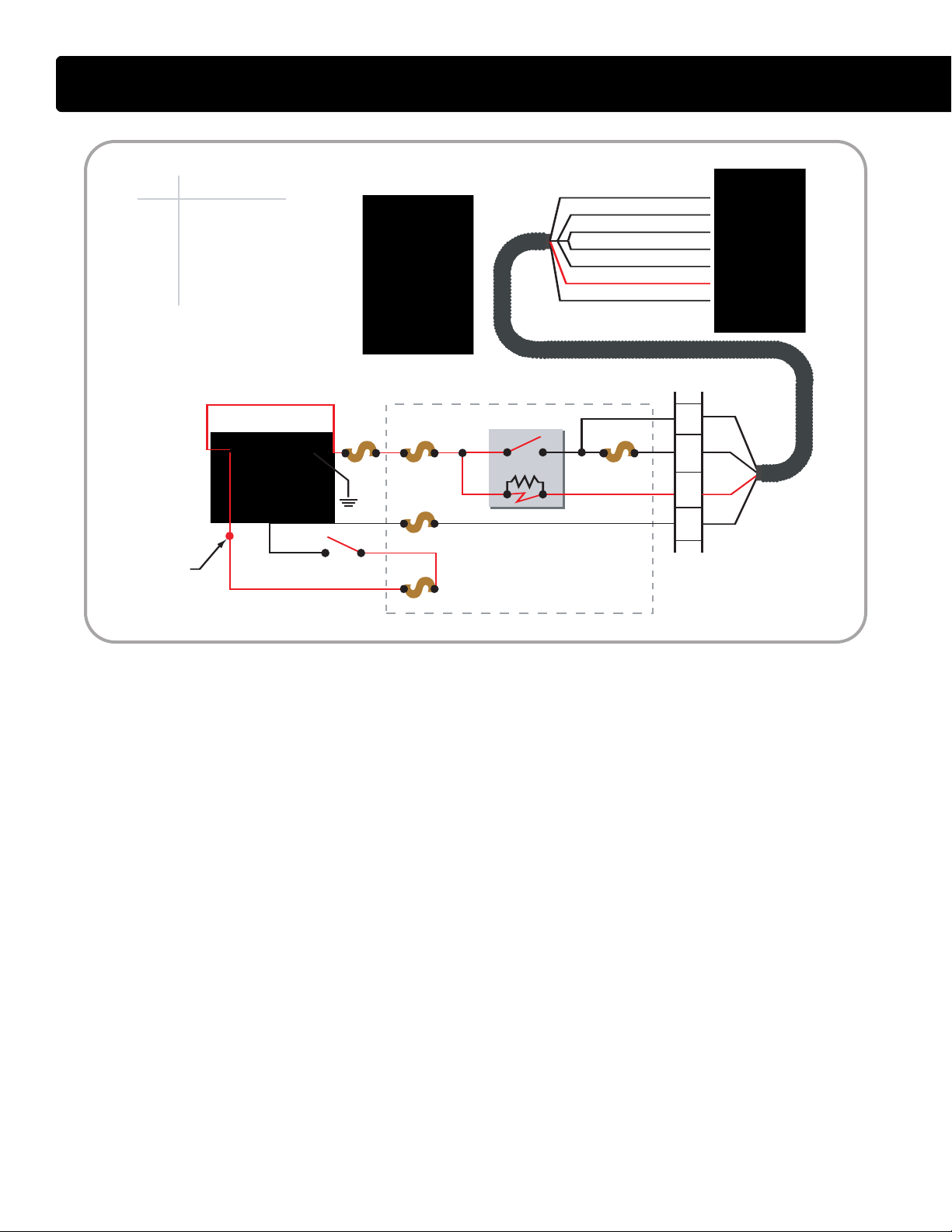
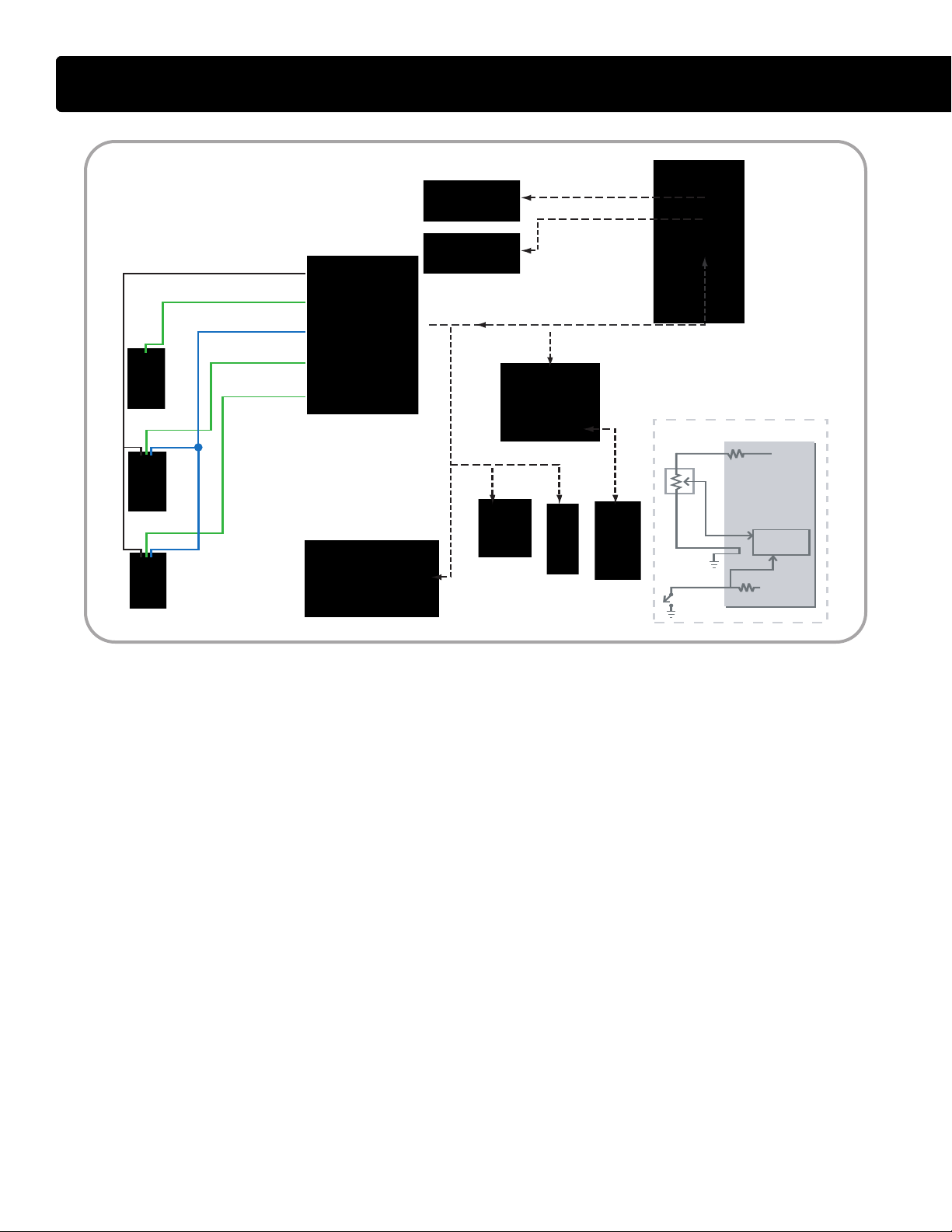
ECM Relay Circuit Operation
• The ECM controls its own power up
and power down process. When
the key is OFF, the ECM stays
powered up for a brief period. The
ECM then powers down after
internal housekeeping functions
have been completed.
Key Power
• The Run/Accessory position of the
key switc
h receives battery voltage
from the Power Distribution Center
(PDC) fuse F-12. When the key is
ON, the switch supplies battery
voltage through fuse F46 to ECM
pin X3-3. Battery voltage is
available at all times through fuses
F4 and F41 to ECM relay pins 1
and 3. The two fuses are in series,
with F4 feeding both the IDM and
ECM relays, and F41 dedicated to
protecting the ECM circuit alone.
Pin 1 supplies voltage to the
relay coil.
• Pin 2 connects the coil to pin X3-5
of the ECM.
• When the key is ON, voltage
supplied to pin X3-3 signals the
ECM that the operator is going to
start the engine. The ECM then
supplies a ground circuit to pin X3-5.
When this occurs, current flows
through the ECM relay coil and
creates a magnetic field causing
the relay to latch. When latched, the
relay connects pin 3 to pin 5 and
supplies current to the ECM
through pin X4-1 and X4-2.
International®VT 275 V6 Engine
Shut Down
• When the key is OFF and volt
removed from ECM pin X3-3, the
ECM shuts down the engine but
keeps the ECM powered up briefly
until the internal house keeping is
completed.
age is
27
Page 28
ECM
BATT ER
Y
200 A F4
F-46
TO IDM RELAY
F-12
R
PDC
F40
2
IDM
STAR TER
MOTOR
RELAY
KEY SWITCH
PDC#
F4
F12
F40
F46
R
Device
30A...IDM/ECM
20A...RUN/ACC
10A...IDM LOGIC
5A...ECM KEY PWR
IDM RELAY - POSITION 55
X1
X2
X3
X1
X2
X3
X3-8 IDM LOGIC POWER
X3-24 IDM M AIN POWER
X3-25 IDM MAIN POWER
X3-4 IDM M AIN POWER
X3-23 IDM M AIN POWER
X3-27 IDM M PR
X3-7 V
IGN
12
6
8
9
ENGINE IN-LINE
12-WAY
30 87
85 86
2
X1
X2
X3
X4
X1
X2
X3
X4
ELECTRONIC CONTROL SYSTEM
IDM Relay Circuit Operation
• The IDM controls its own power up
and power down process. When
the key is OFF, the IDM stays
powered up for a brief period. The
IDM then powers down after
internal housekeeping functions
have been completed.
IDM Power Up
• The key switch receives battery
age from the Power Distribution
volt
Center (PDC) F-12 fuse. When the
key is ON, the switch supplies
battery voltage through F-46 fuse
and pin 9 of the engine 12-way
connector to pin X3-7 of the IDM.
• Battery voltage is available through
the PDC F-4 fuse to IDM relay pin
30 and 85 at all times. Pin 85
supplies voltage to the relay coil.
Pin 86 takes that voltage through
pin 8 of the engine 12-way
connector to pin X3-27 of the IDM.
When the key is ON, voltage
supplied to pin X3-7 signals the
IDM to provide a ground circuit to
pin X3-27. When this occurs,
current flowing through the IDM
relay coil builds a magnetic field
that causes the relay to latch. When
latched, the relay connects pin 30
to pin 87 and supplies current
through pin 12 of the engine in-line
12-way connector to pin X3-4, X323, X3-24, and X3-25 of the IDM.
Four pins receive voltage to spread
the current draw over multiple pins.
IDM Logic
• The IDM also requires volt
age for
the internal logic circuit. When the
IDM relay latches, pin 87 of the relay
supplies voltage to the IDM logic
circuit through the F-40 fuse in the
PDC. The F-40 fuse feeds through
pin 6 of the engine in-line 12-way
connector to the IDM pin X3-8.
28
International®VT 275 V6 Engine
Page 29
ELECTRONIC CONTROL SYSTEM
ECM
VOLTAGE
RR
SENSOR
IDM
ECM
X1
X2
X3
X4
E DC BA
IAT
X1-7 IAT
X1-6 GRD
X1-8 ECT
X2-1 EOT
X2-14 MAT
MAF / IAT
EGR
DRIVE
MODULE
IAH RELAY
GLOW PLUG
RELAY
BCS
IPR
EGR
VALVE
ECT
EOT
MAT
RIGHT BANK INJECTORS
LEFT BANK I NJECTORS
REFERENCE
VOLTAGE
MICROPROCESSOR
R
R
1
1
2
2
X1
X2
X3
X1
X2
X3
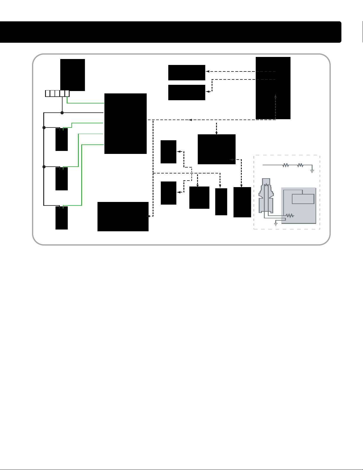
Temperature Sensor Operation
• There are four, two-wire temperature sensors on the VT 275
engine. Each sensor contains a
resistor whose value varies depending on temperature. The ECM
supplies a separate reference
voltage to each temperature sensor.
Then, the sensor conditions its
voltage to produce the sensor signal.
Sensor Circuit
• A temperature variable resistor is a
thermistor
connected to a current-limiting
resistor of fixed value within the
. Each thermistor is
ECM. The thermistor and the
resistor make a series circuit with a
reference voltage applied at one
end and a ground at the other. The
voltage in the circuit between the
two resistors changes as the
thermistor's resistance changes.
When the temperature is low, the
sensor's resistance is high and the
signal voltage is high. When the
temperature is high, the resistance
is low and the signal voltage is low.
Engine Coolant Temperature
(E
CT) Sensor
• The ECT sensor is mounted in the
front cover. The body of the sensor
is exposed to coolant as it returns
from the cylinder heads. The ECT
signal is input into the optional
engine warning protection system,
coolant compensation, glow plug
operation and the instrument
cluster temperature gauge.
Engine Oil Temperature
OT) Sensor
(E
• The EO
oil filter adapter. The EOT signal
allows the ECM to compensate for
viscosity changes in the oil due to
temperature. The EOT signal is
input into calculations that
determine the fuel quantity and timing.
T sensor is mounted in the
International®VT 275 V6 Engine
Manifold Air Temperature
(MAT) Sensor
• The MAT sensor is mounted
towards the front of the left bank leg
of the intake manifold. T
sensor measures the temperature
of the air in the intake manifold. The
ECM uses this information in
calculations that control the EGR
valve operation.
Intake Air Temperature
T) Sensor
(IA
• The IAT sensor is contained within
the Mass Air Flow (MAF) sensor
housing. The MAF sensor is
mounted to the inlet duct leading to
the turbocharger. The ECM uses
the IAT information to control
injection timing and fuel rate when
starting cold.
he MAT
29
Page 30
ECM
IDM
ECM
X1
X2
X3
X4
EGR
DRIVE
MODULE
BCS
IPR
EGR
VALVE
EOPS
ICP
MAP
RIGHT BANK INJECTORS
LEFT BANK I NJECTORS
REFERENCE
VOLTAGE
MICROPROCESSOR
SWITCH
Functional Equivelant
X1-6 GRD
X1-13 EOPS
X1-14 V
REF
X1-20 ICP
X2-3 MAP
X1
X2
X3
X1
X2
X3
VREF
SENSOR
ELECTRONIC CONTROL SYSTEM
Pressure Sensor Operation
• The Manifold Absolute Pressure
(MAP) sensor, the Injection Control
Pressure (ICP) sensor and the
Engine Oil Pressure Switch
(EOPS) are used to send pressure
information to the ECM.
• The MAP and ICP are three-wire
pressure sensors. Three-wire
pressure sensors receive a
reference voltage and a ground
from the ECM. The sensor returns a
portion of the reference voltage,
proportional to the pressure, back
to the ECM as a signal.
Injection Control Pressure
(ICP) Sensor
• The ICP sensor is a Micro Strain
Gauge (M
MSG type sensor has a small strain
gauge that senses changes in
pressure. Sensor mounted
electronic circuitry converts the
30
SG) style sensor. The
• T
change into a signal voltage
proportional to the pressure being
measured. The ICP sensor is used
to make corrections to the IPR
signal and to continually check the
performance of the Injection
Control Pressure system.
Manifold Absolute Pressure
(MAP) sensor
he MAP sensor is a variable
capacitance style sensor. In a
variable capacitance sensor, the
pressure being measured deflects a
ceramic disk towards a metal disk.
The two materials make up a
variable capacitor. Sensor mounted
circuitry converts the capacitance
into a signal voltage proportional to
the measured pressure. The MAP
sensor measures turbocharger
boost in the intake manifold. The
MAP signal is input into calculations
that determine fueling quantities
and the desired EGR valve position.
International®VT 275 V6 Engine
Engine Oil Pressure Switch
(EOPS)
• The EOPS is used to detect oil
pressure and is an input to the dash
cluster and the engine warning
protection system. T
he switch is
normally open with the engine off
but closes when oil pressure
reaches 5 to 7 psi. The ECM sends
5 volts through a current limiting
resistor to the EOPS and reads the
voltage between the resistor and
the switch. When oil pressure is
low, the switch is open and the
ECM reads 5 volts.
When the oil pressure is greater
than 5 to 7 psi, the switch is closed,
the circuit is shorted to ground, and
the ECM reads a low voltage.
When the ECM detects oil pressure, MasterDiagnostics
®
will display
40 psi. When the oil pressure is
below 5 psi, MasterDiagnostics
will display 0 psi.
®
Page 31

ELECTRONIC CONTROL SYSTEM
IDM
CAMSHAFT
POSITION
SENSOR
ECM
X1
X2
X3
X4
X1
X2
X3
X4
RIGHT BANK INJECTORS
CKPO X3-5
CMPO X3-10
CKP (+) X1-1
CKP (-) X1-2
CMP (+) X1-9
CMP (-) X1-10
CKPO X1-19
CMPO X1-24
LEFT BANK INJECTORS
CRANKSHAFT
POSITION
SENSOR
1
2
1
2
+
-
+
-
X1
X2
X3
X1
X2
X3
Magnetic Pick-Up Sensors
• The Camshaft Position (CMP)
sensor and Crankshaft Position
(CKP) sensor are both magnetic
pick-up type sensors. Each sensor
contains a permanent magnet core
surrounded by a coil of wire. The
sensor generates a signal through
the collapse of a magnetic field
created by a moving metal trigger.
Movement of the trigger induces an
Alternating Current (AC) voltage in
the sensor coil.
Camshaft Position
(CMP) Sensor
• The CMP sensor is mounted on the
left front of the crankcase. T
CMP sensor reacts to a single peg
pressed into the camshaft. The peg
passes the sensor once per
camshaft revolution producing an
AC signal in the coil.
he
• The ECM uses the AC signal to
determine the position of the
camshaft. The ECM converts the
AC signal to a square wave output.
The output signal, Camshaft
Position Output (CMPO), is sent to
the IDM for fueling calculations.
The ECM conditions the CMP
signal and sends it out as the TACH
signal for body builder use.
Crankshaft Position
(CKP) Sensor
• The CKP sensor is mounted on the
right front of the lower crankcase.
The CKP sensor reacts to a sixtyminus-two tooth trigger wheel
affixed to the front of the crankshaft.
The sensor produces pulses for
eac
h of the 58 teeth as they pass
the magnet. The two tooth gap
allows the ECM to calculate the
position of the crankshaft.
• The ECM uses the CKP signal to
determine the position and speed
of the crankshaft. The ECM
converts the AC signal to a square
wave output, Crankshaft Position
Output (CKPO), and sends it to the
IDM for fueling calculations.
• The ECM needs both the CKP and
CMP signals to calculate engine
speed and crankshaft position.
From the CKP signal the ECM can
determine the speed of the
crankshaft and the position of each
piston relative to Top Dead Center.
From the CMP sensor the ECM can
determine the current stroke of
each (i.e., compression or exhaust).
International®VT 275 V6 Engine
31
Page 32

ECM
BATT ERY
200 A
IAH
RELAY
GLOW PLUG
RELAY
GPC
GPD
GLOW PLUGS
ECT
STAR TER IAH
BAP
X1-17 GPC
X1-21 GPD
246
135
4
12-WAY
ENGINE TO CHASSIS
CONNECTOR
N.O. TERMINAL
X1
X2
X3
X4
X1
X2
X3
X4
ELECTRONIC CONTROL SYSTEM
Glow Plug System
• The VT 275 uses glow plugs to aid
cold starts. The ECM turns on the
glow plugs prior to engine cranking
to increase the temperature of the
cylinders. Glow plug operation is
controlled by the ECM through the
glow plug relay. The glow plugs
have full voltage if battery voltage is
normal, or pulse width modulated to
control the current if battery voltage
is above normal.
The ECM calculates glow plug ontime based on coolant temperature
and barometric pressure. The
required time to warm up the
cylinders decreases as engine
coolant temperature increases.
Warm up time decreases as
barometric air pressure increases.
The glow plugs may continue to be
energized after start-up to
reduce emissions.
Relay Operation
• The glow plug relay receives battery
voltage to its common terminal from
the starter power-feed terminal. The
normally open terminal connects to
the individual glow plugs through
the glow plug harness. One end of
the relay coil is always grounded
through pin 4 of the engine 12-way
connector. The ECM supplies 12
volts to the other end of the coil
through ECM pin X1-17 in order to
close the relay contacts.
Glow Plug Lamp
• The glow plug lamp is used as a
wait-to-st
art indicator. The ECM
lights the glow plug lamp at glow
plug activation to signal the
operator to wait for the cylinders to
warm up.
• Both lamp operation and the glow
plug operation are based on BAP
and ECT values but are independent of each other.
• The glow plug operation may
continue after the lamp is off.
Glow Plug Diagnostics
• Glow plug diagnostics are used to
determine if the relay is operating
correctly when commanded on. An
additional wire on the relay's
normally open terminal connects to
E
CM pin X1-21. This circuit, GPD,
allows the ECM to monitor the
relay operation.
• The glow plugs can be turned on
using the KOEO Glow Plug/Inlet
Air Heater Test. The test can only
be activated twice per key cycle.
32
International®VT 275 V6 Engine
Page 33

ELECTRONIC CONTROL SYSTEM
ECM
BATT ERY
200 A
IAHC
IAHD
MAF / IAT
IAH
RELAY
EOT
STAR TER IAH
BAP
X1-18 IAHC
X2-11 IAHD
N.O. TERMINAL
4
12-WAY
ENGINE TO CHASSIS
CONNECTOR
X1
X2
X3
X4
X1
X2
X3
X4
Inlet Air Heater Operation
• The VT 275 has an Inlet Air Heater
(IAH) element mounted in the front
of the intake manifold. The IAH is
used to improve cold start
operation, reduce emissions and
white smoke, and improve engine
warm-up. When the key is ON, the
ECM determines if the element
should be activated and for how
long, based on barometric pressure
and engine oil temperature. On time
is limited to prevent heater element
damage and to prevent damage to
the intake manifold.
The heater relay delivers full voltage
to the element if battery voltage is
normal, or the relay is pulsed by the
ECM to control the current if battery
voltage is above normal. If the
battery voltage is so low that the
starter motor operation may be
Inlet Air Heater Diagnostics
• An additional wire on the normally
open terminal connects to E
CM pin
X2-11. This diagnostic circuit
allows the ECM to determine if the
IAH relay is on when commanded
on by the ECM.
affected, the inlet air heater is disabled.
• The Inlet Air Heater can be turned
Relay Operation
he IAH relay receives battery
• T
power from the starter power feed
terminal. The normally open terminal
connects to the element through
the harness. One end of the relay
on using the KOEO Glow
Plug/Inlet Air Heater Test. The test
can only be activated twice per key
cycle. The ECM will delay the Inlet
Air Heater operation for three
seconds after the test is activated.
coil is always grounded through pin
4 of the engine 12-way connector.
The other end of the coil receives
12 volts from ECM pin X1-18 to
close the relay contacts.
International®VT 275 V6 Engine
33
Page 34

IDM
ECM
X1
X2
X3
X4
EDCBA
MAF / IAT
EGR
DRIVE
MODULE
BCS
IPR
EGR
VALVE
RIGHT BANK INJECTORS
X1-7 IAT
X1-6 IAT SIG G RD
X2-2 MAF
LEFT BANK I NJECTORS
FIXED
RESISTOR
HEATED
ELEMENT
FIXED
RESISTOR
THERMISTOR
MAF
ECM
VREF
SIG
GRD
MICROPROCESSOR
4
9
ENGINE
IN-LINE 12-WAY
CONNECTOR
ACT GRD
KEY PWR
MAF SIGNAL
KEY POWER
ACTUATOR GRD
SIGNAL GRD
IAT
B+
B+
SIGNAL
CONTROL
X1
X2
X3
X1
X2
X3
ELECTRONIC CONTROL SYSTEM
Mass Air Flow (MAF) Sensor
• The MAF sensor is used to measure
the mass of the fresh air portion of
the intake air charge. To reduce
Oxides of Nitrogen (NOx), a portion
of the fresh air charge is displaced
with cooled exhaust gases.
The ECM calculates the total
engine gas flow based on MAT,
MAP and RPM. The ECM then
determines the required EGR
percent based on the current
engine operating conditions. At this
point, the ECM commands the
exhaust portion of the total charge
through the EGR valve while
monitoring the fresh air portion
through the MAF sensor.
Sensor Construction
• The sensor housing contains two
sensors, the MAF sensor and the
Intake Air Temperature (IAT) sensor.
The MAF sensor contains a heated
element placed in the air stream.
The amount of electrical power
needed to maintain the element at
the proper temperature depends
directly on the mass of air moving
over the element.
Sensor Operation
• The MAF sensor is made up of two
age divider circuits. A thermistor
volt
and a fixed resistor make up one
voltage divider circuit, and the
heated element and a fixed resistor
make up the other voltage divider
circuit. The two voltage divider
circuits are combined into a bridge
circuit with a common power supply
and a common ground.
• During operation, when voltage is
applied to the bridge, the
temperature of the heated element
increases and the resistance
decreases. This affects the output
of the divider circuit.
The thermistor side is affected only
by ambient air temperature. The
divider voltages are compared and
the input voltage to the bridge is
increased or decreased until both
divider voltages are equal.
An increase or decrease in airflow
will change the ratio between the
divider voltages, which results in a
change to the supply voltage.
The signal controller circuit
measures the voltage to the bridge
and, based on that value, sends a
frequency signal to the ECM. The
correct key-on, engine-off
frequency is 400+
100 Hz.
34
International®VT 275 V6 Engine
Page 35

ELECTRONIC CONTROL SYSTEM
ECM
BATT ERY
200 A
F11
F19
HFCM
PDC
FUEL
PUMP
RELAY
FUEL HEATER RELAY
TO KEY SWITCH
TO
RUN / ACC
RELAY
X3-9 FPC
X4-15 FPM
X3-1 WIF
GRD
PUMP
HEATER
TO
IGNITION
POWER
1
2
2
1
2
1
3
1
25
3
1
25
X1
X2
X3
X4
X1
X2
X3
X4
PDC#
F11
F19
Device
20A...FUEL PUMP
20A...FUEL HEATER
Pump Operation
• The VT 275 has an ECM controlled
chassis mounted electric fuel pump.
At key-on, the ECM will operate the
fuel pump for up to 60 seconds to
prime the system. Priming allows
the pump to pressurize the system
and to allow air in the system to
bleed out through an orifice
between the filter housing and the
fuel return circuit.
When the engine is in run mode, the
pump will operate continuously. If
the engine dies or is shut down, or
if it is not started within 60 seconds, the ECM will stop the pump.
Circuit Operation
• To operate the pump, the ECM
provides a ground at ECM pin X3-9
to latch the fuel pump relay. The
relay takes power from fuse F11
and provides it to pin 1 of the pump
connector. The ECM monitors the
relay's operation through ECM pin
X4-15. Battery voltage should be
present at X4-15 when the relay is
commanded on. If the ECM does
not detect the voltage, a DTC will
be logged.
Fuel Heater
• The Horizontal Fuel Conditioning
Module (H
heater. When the key is ON, the fuel
heater relay latches and provides
power to pin 1 of the heater
connector. The heater element
contains a thermostat that
controls the heater operation.
FCM) contains a fuel
Water-In-Fuel Sensor
• The pump module contains a
Water-In-Fuel (W
IF) sensor. The
WIF sensor receives voltage from
the key switch. If the filter detects
water, the sensor sends the voltage
to ECM pin X3-1. The ECM then
activates the dash WIF lamp.
International®VT 275 V6 Engine
35
Page 36

ECM
APS / IVS
IN CAB CRUISE SWITCH ES
TO KEY SWITCH
F46
BAP
IDM
EGR
DRIVE
MODULE
BCS
IPR
EGR
VALVE
RIGHT BANK INJECTORS
LEFT BANK I NJECTORS
A
B
C
E
D
F
PDC
X4-6 COO
X3-14 RAS
X3-21 SCS
X3-24 BAP
X4-18 APS
X4-24 GRD
X4-4 V
REF
B
X4-12 IVS
X1
X2
X3
X1
X2
X3
X1
X2
X3
X4
X1
X2
X3
X4
PDC#
F46
Device
5A...ECM KEY PWR
ELECTRONIC CONTROL SYSTEM
Accelerator Pedal Position
Sensor / Idle Validation Switch
(APS/IVS)
• The APS/IVS sensor has two
components built into one housing:
the Accelerator Pedal Position
Sensor (APS) and the Idle
Validation Switch (IVS).
• The APS is a potentiometer type
sensor. The ECM supplies a
reference voltage (Vref) and ground
to the potentiometer and the sensor
sends a voltage signal back to the
ECM indicating the pedal position.
The idle validation switch receives
12 volts from the chassis harness
and signals the ECM when the
pedal is in the idle position. If the
ECM detects an APS signal out of
range high or low, the ECM will
ignore the APS signal and operate
at low idle.
• If a disagreement in the state of IVS
and APS is detected by the ECM,
and the ECM determines that the
IVS is at fault, the ECM will allow a
maximum of 50% of APS. If the
ECM cannot determine that the IVS
is at fault, the engine will be
restricted to low idle only.
Barometric Absolute Pressure
(BAP) sensor
• The BAP sensor is mounted in the
cab. The BAP sensor provides
altitude information to the E
fuel quantity and timing, glow plug
on time, intake heater on time, and
the operation of the Boost Control
CM, so
Solenoid can be adjusted to
compensate for air density
changes.
Cruise Control
• Cruise control operation is
controlled through the E
CM. Two
switches in the cab are used to
signal the operator's intention for
speed control. The switches receive
battery voltage through fuse 46 in
the Power Distribution Center
(PDC). The Cruise On/Off (COO)
switch sends a voltage signal to
ECM pin X4-6. With the COO
switch on, the operator can use the
Set (SCS) and resume (RES)
switch to control the vehicle speed.
36
International®VT 275 V6 Engine
Page 37

ELECTRONIC CONTROL SYSTEM
IDM
ECM
EGR DRIVE
MODULE
X1
X2
X3
X4
X1
X2
X3
X1
X2
X3
X4
X1
X2
X3
5
2
3
4
1
6
7
8
16
X2-13 X3-31
X2-6
X2-12 SHD
X3-30
WV U
SENSOR GRD
POSITION SENSOR W
POSITION SENSOR V
POSITION SENSOR U
SENSOR 5V SUPPLY
SHIELD DRAIN
MOTOR W
MOTOR V
MOTOR U
CAN2CAN2+
GRD
ACT PWR
15
14
13
12
11
10
9
8
7
6
5
4
3
2
1
EGR
VALVE
10
4
ENGINE IN-LINE
RELAY
TO ECM RELAY
‘NORMALLY OPEN’
TERMINAL
TO FRAME
GROUND
EGR DRIVE MODULE
EGR VALVE
POWER
GRD
POWER
GRD
S
S
S
S
S
SNN
N
N
N
N
EGR System
• The motor-actuated EGR valve is
controlled and monitored by the
EGR Drive Module. The module is
connected to the engine CAN 2 link
allowing bi-directional communication with the ECM.
EGR Valve
• The EGR Valve poppet stem is
positioned by a three-phase motor
The armature of the motor has
twelve permanent magnet
segments alternating as north or
south poles of a magnet. The
armature is surrounded by nine field
coils divided into three sets or
phases. Each phase has three coils
wired in parallel and spaced 120°
apart around the motor armature.
One lead of each coil set is
connected to the respective motor
circuit on the drive module. The
other leads from all of the nine coils
are joined together.
Two coil sets are powered together
to reposition the motor, with one set
connected to power and the other
to ground. Each powered coil set
creates either a north or a south
magnetic field depending on the
direction of current flow through
the coils.
Drive Module Operation
• The direction of current flow
.
through the coil sets is controlled
by the EGR Drive Module. When
the integrated circuit in the module
connects one coil set to ground,
and one of the other two coil sets to
a Pulse Width Modulated (PWM)
power source, the magnetic fields
created by the coils oppose the
armature magnetic fields and a
controlled rotation of the
armature occurs.
International®VT 275 V6 Engine
The drive module constantly
switches the coil sets (identified as
Motor W, V, and U) from power and
ground to continually produce
rotation. Pulse width modulation is
used to control the current.
Communication
• Three Hall-Effect sensors are
located on a circuit board at the top
of the valve housing. The sensors
are supplied power and ground
through the drive module and
produce a series of signals so the
module can track the rotation of the
motor and the opening position of
the valve.
37
Page 38

IDM
EGR DRIVE
MODULE
ECM
X1
X2
X3
X4
4
3
2
3
ENGINE IN-LINE
12-WAY CO NNECTOR
9-WAY DIAGNOSTIC
CONNECTOR
F
G
D
C
EGR
DRIVE MODULE
CONNECTOR
X1-19 CKPO X3-5
X3-28
X3-29
X1-24 CMPO X3-10
X2-6 CAN 2 (+) X3-30
X2-13 C AN 2 (-)
X3-12 C AN 1 (+)
X3-13 C AN 1 (-)
X4-20 ATA (+)
X4-21 ATA (-)
X3-31
X1
X2
X3
X1
X2
X3
X1
X2
X3
X4
TO TRANS
CONTROLLER
ELECTRONIC CONTROL SYSTEM
ECM/IDM Communications
• The ECM and IDM communicate
over three independent communication links. The three links are
CMPO, CKPO, and CAN 2. In
addition to communications with
the IDM, the ECM also sends
engine information over the CAN 1
link to the vehicle's instrument
cluster and the 9-pin
Diagnostic connector.
CAN 2
• The engine CAN 2 link is a twowire, bi-directional communication
circuit between the ECM and IDM
and the E
Module. The ECM and IDM use the
link to share operating strategies,
sensor information, diagnostic
demands, and Diagnostic Trouble
Codes (DTC). The ECM also shares
desired EGR valve position with the
EGR drive module over the CAN 2
link. The EGR Drive Module
38
CM and the EGR Drive
translates those messages and
then commands the EGR valve
motor. The EGR drive module
monitors the valve action and
communicates any faults back to
the ECM over the CAN 2 link.
Cam Position Output (CMPO)
• The CMPO signal is a 0-12V digital
signal used to communicate the
camshaft position to the IDM. The
CMPO signal is a square wave
signal derived from the information
contained in the camshaft position
sensor's AC voltage signal. The
ECM generates the CMPO signal
by pulling down (switching to
ground) a single wire 12V circuit
that originates in the IDM. The IDM
reads the signal and uses it for
injector timing calculations.
Crank Position Output (CKPO)
• The CKPO signal is a 0-12V digital
signal used to communicate the
International®VT 275 V6 Engine
crankshaft position and speed to
the IDM. The CK
PO signal is a
square wave signal derived from the
information contained in the
crankshaft position sensor's AC
voltage signal. The ECM generates
the CKPO signal by pulling down
(switching to ground) a single wire
12V circuit that originates in the
IDM. CKPO is used by the IDM for
injector timing and fuel quantity
calculations.
American Trucking Association
(A
TA)
• The ATA link is a 0-5V signal that
enables communications between
the E
CM and the MasterDiagnostics software. The data
communication link also allows for
programming of the ECM and IDM.
Page 39

ELECTRONIC CONTROL SYSTEM
ECM
F34
F12
PDC
FUNCTION SELECTOR
SWITCH
HPSW LPSW T-STAT SW
ECT
TO
TRANS
CONTROLLER
X3-10 AC DEMAND
CAN1+
CAN 1(+)
CAN1-
CAN 1(-)
X3-22 AC CONTR OL
TO IGN
SW
IGNITION
SWITCH
200A
MEGA
FUSE
TO BATTERY
POSITIVE
h
X1
X2
X3
X4
X1
X2
X3
X4
7
5
1
CA
2
CMP
APS
BATTERY
GRD
A/C
CLUTCH
A/C CLUTCH
DIODE
A/C CLUTCH
RELAY
3
5
1
2
A/C Clutch Control
• The VT 275 ECM controls the A/C
clutch. The ECM receives an A/C
demand signal from the chassis,
and engages the A/C clutch if
engine conditions are correct. If
conditions are not right, clutch
action may be delayed. When the
ECM receives the A/C demand
signal, it considers engine run time
(to avoid stalling at start up) and
engine coolant temperature (to
avoid compressor operation when
liquid refrigerant may be present in
the compressor). In addition, the
ECM looks at transmission shift
action (to avoid clutch action during
a transmission shift), engine RPM
(to avoid clutch overspeed), and
APS percent (to avoid engagement
during full throttle acceleration).
A/C Demand
• The A/C demand signal originates
at the E
CM as a reference voltage
on X3-10. The ECM supplies 5
volts to pin 10 and considers clutch
engagement when the voltage is
pulled low (shorted to ground) by
the A/C on/off switch in the dashlocated A/C Control Head.
The low-pressure switch (LPSW),
high-pressure switch (HPSW), and
the thermostat switch (T-STAT SW)
are in series in the A/C demand
circuit. If the compressor head
pressure rises above 350 psi, the
high-pressure switch opens and the
demand signal will be 5V. If
pressure on the low side of the
compressor goes below 7 psi, the
low-pressure switch will open and
the demand signal will be 5V.
The last switch is the thermostat
control in the A/C Control Head. If
the thermostat is positioned so that
in-cab temperature demands are
satisfied, the thermostat will open
and the demand signal will be 5V.
International®VT 275 V6 Engine
A/C Control
• If the A/C demand signal is pulled
low and the E
CM determines that
the clutch can be engaged, the
ECM pulls the AC Control circuit
low at pin X3-22. When pin 22 is
low, a ground is provided for the
A/C Clutch Relay. The relay latches
and battery voltage is provided to
the A/C clutch through pin 5 of the
engine 12-way connector.
Switches
• The thermostatic switch (T-STAT
W) monitors evaporator core
S
temperature to prevent freezing and
to regulate cab temperatures.
• The low pressure switch (LPSW)
prevents compressor damage in the
event of a refrigerant leak.
• The high pressure cutoff Switch
(HPSW) interrupts compressor
operation in the event of high
system pressures.
39
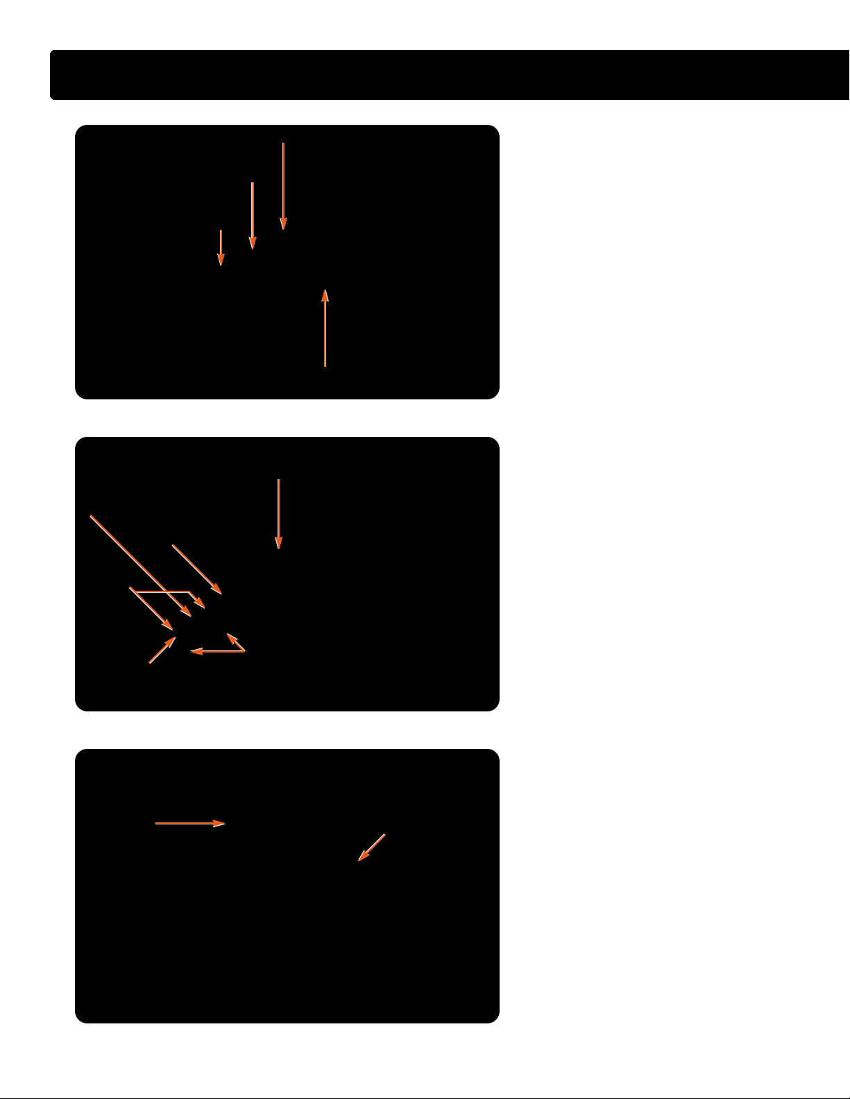
Page 40

Inlet air
Compressed air
Exhaust gas
Crankcase vapors
Charge Air Cooler
(CAC)
Air filter
MAF/IAT
sensor
Dual stage
turbocharger
Normal exhaust
flow bypass
shut
Exhaust flow
bypass open
Right
exhaust in
Left
exhaust in
IAH
MAP
Right cylinder
head
Right exhaust
manifold
Exhaust system
Left cylinder
head
Left exhaust
manifold
MAT
EGR
valve
Intake
manifold
EGR
cooler
Exhaust tube assembly
Exhaust to dual stage
turbocharger
Left Right
Air Management
System
• Regulated two-stage turbocharger
• Cooled exhaust gas recirculation
• Intake air heater
®
System Features
• The Air Management System consists of
the air filter, two-stage turbocharger,
charge air cooler, intake manifold,
Exhaust Gas Recirculation (EGR) cooler
and EGR valve. The mass air flow
sensor, the intake air temperature
sensor, the manifold air temperature
sensor, the manifold absolute pressure
sensor, and the EGR valve position
sensors within the EGR valve are all
inputs from the system to the ECM. The
ECM controls the system through the
EGR valve, and the turbocharger boost
control solenoid.
40
International®VT 275 V6 Engine
Page 41

LLOOWW PPRREESSSSUURREE
LLOOWW PPRREESSSSUURREE
CCOOMMPPRREESSSSOORR IINNLLEETT
CCOOMMPPRREESSSSOORR IINNLLEETT
IINNTTAAKKEE MMAANNIIFFOOLLDD
IINNTTAAKKEE MMAANNIIFFOOLLDD
AIR MANAGEMENT SYSTEM
FFRROOMM CCHHAARRGGEE AAIIRR CCOOOOLLEERR ((CCAACC))
FFRROOMM CCHHAARRGGEE AAIIRR CCOOOOLLEERR ((CCAACC))
EEGGRR VVAALLVVEE
EEGGRR VVAALLVVEE
BBOOOOSSTT CCOONNTTRROOLL SSOOLLEENNOOIIDD
BBOOOOSSTT CCOONNTTRROOLL SSOOLLEENNOOIIDD
PPNNEEUUMMAATTIICC AACCTTUUAATTOORR
PPNNEEUUMMAATTIICC AACCTTUUAATTOORR
CCOOMMPPRREESSSSOORR OOUUTTLLEETT TTOO
CCOOMMPPRREESSSSOORR OOUUTTLLEETT TTOO
CCHHAARRGGEE AAIIRR CCOOOOLLEERR ((CCAACC))
CCHHAARRGGEE AAIIRR CCOOOOLLEERR ((CCAACC))
LLOOWW PPRREESSSSUURREE
LLOOWW PPRREESSSSUURREE
TTUURRBBIINNEE OOUUTTLLEETT
TTUURRBBIINNEE OOUUTTLLEETT
System Operation
• The VT 275 uses a regulated twostage turbocharger to boost the
volume of air flowing into the
cylinders. The system consists of
two turbochargers with exhaust
flow through the units controlled by
the turbocharger boost control
solenoid. The smaller of the two
turbochargers is identified as the
high-pressure turbocharger and is
sized to provide boost for low to
medium speeds. The larger
turbocharger is the low-pressure
turbo and is sized to work in tandem
with the high-pressure unit to
provide the boost and air flow
needed for high-speed, high-load
engine conditions.
• Air passes through the air filter
element and the mass air flow
sensor to enter the compressor of
the low-pressure turbocharger. Air
that leaves the low-pressure
EEXXHHAAUUSSTT TTUUBBEE AASSSSEEMMBBLLYY
EEXXHHAAUUSSTT TTUUBBEE AASSSSEEMMBBLLYY
compressor flows through the
crossover tube to the compressor
inlet of the high-pressure turbocharger. Air from the compressor
goes to the Charge Air Cooler (CAC).
• The CAC is mounted in front of the
radiator. The cooler is an air-to-air
heat exchanger that uses airflow to
remove heat energy from the
pressurized intake charge. Reducing the temperature of the air
increases the charge density, which
results in a more efficient engine
with quicker engine response and
reduced emissions.
• After the CAC, the air flows through
piping to the intake manifold where
it is distributed to the cylinders.
• Exhaust flow from the cylinders
exits the exhaust manifolds and
spools up the high-pressure turbine.
The exhaust passes through the
high-pressure turbine and enters
the low-pressure turbine. The
exhaust gases then exit the turbine
and flow out the exhaust system.
• A bypass valve controls the exhaust
flow through a passage that allows
a portion of the exhaust to bypass
the high-pressure turbine and go
directly to the low-pressure turbine.
Part of the exhaust gas that leaves
the left bank exhaust manifold is
diverted to the EGR cooler. Heat
energy is removed from the exhaust
while in the cooler and transferred
to the engine's coolant. The cooled
exhaust gases then flow through a
short internal passage in the intake
manifold to the EGR valve. The
EGR valve meters a portion of the
cooled exhaust gases into the
intake manifold where the exhaust
displaces a portion of the fresh
air charge.
International®VT 275 V6 Engine
41
Page 42

AIR MANAGEMENT SYSTEM
FFIILLTTEERR
RREESSTTRRIICCTTIIOONN
GGAAUUGGEE
Air Filter Restriction Gauge
• The filter restriction gauge is mounted on
the air filter housing. The gauge allows the
operator to check the condition without
removing the filter. The restriction gauge
can be reset by pushing the yellow button
on the end.
• Note: The filter restriction gauge bellows
k in position if restriction exceeds
will loc
26 inches of water. The filter should be
replaced and the gauge reset.
• The filter element should be replaced if
restriction passes 12.5 inches of H
when tested at high-idle, no-load with a
magnehelic gauge.
O
2
IINNTTAAKKEE MMAANNIIFFOOLLDD
IINNTTAAKKEE MMAANNIIFFOOLLDD
EEGGRR VVAALLVVEE
EEGGRR VVAALLVVEE
Intake Manifold
• The intake manifold directs air from the
charge air cooler to the intake ports in the
cylinder heads. The manifold also provides
an internal passage for exhaust gases from
the EGR cooler to reach the EGR valve.
Exhaust gas will flow into the intake
manifold and mix with the intake charge
when the EGR valve is open and the
exhaust backpressure is higher than the
boost pressure.
• The manifold has an additional internal
passage for coolant from the EGR cooler
to return to the front cover.
42
International®VT 275 V6 Engine
Page 43

AIR MANAGEMENT SYSTEM
LLOOWW PPRREESSSSUURREE
LLOOWW PPRREESSSSUURREE
CCOOMMPPRREESSSSOORR
CCOOMMPPRREESSSSOORR
HHOOUUSSIINNGG
HHOOUUSSIINNGG
LLOOWW PPRREESSSSUURREE
LLOOWW PPRREESSSSUURREE
TTUURRBBIINNEE
TTUURRBBIINNEE
HHOOUUSSIINNGG
HHOOUUSSIINNGG
FFRROOMM AAIIRR FFIILLTTEERR
FFRROOMM AAIIRR FFIILLTTEERR
EEXXHHAAUUSSTT OOUUTTLLEETT
EEXXHHAAUUSSTT OOUUTTLLEETT
PPNNEEUUMMAATTIICC
PPNNEEUUMMAATTIICC
AACCTTUUAATTOORR
AACCTTUUAATTOORR
HHIIGGHH PPRREESSSSUURREE
HHIIGGHH PPRREESSSSUURREE
TTUURRBBIINNEE HHOOUUSSIINNGG
TTUURRBBIINNEE HHOOUUSSIINNGG
HHIIGGHH PPRREESSSSUURREE TTUURRBBIINNEE
HHIIGGHH PPRREESSSSUURREE TTUURRBBIINNEE
TTOO CCAACC
TTOO CCAACC
HHIIGGHH PPRREESSSSUURREE
HHIIGGHH PPRREESSSSUURREE
CCOOMMPPRREESSSSOORR HHOOUUSSIINNGG
CCOOMMPPRREESSSSOORR HHOOUUSSIINNGG
EEXXHHAAUUSSTT IINNLLEETT TTOO
EEXXHHAAUUSSTT IINNLLEETT TTOO
Two-Stage Regulated
Turbocharger
• The dual turbocharger consists of
two turbochargers in series. The
high pressure turbocharger is the
smaller unit and is configured to
provide boost at low speeds and
loads. The low pressure turbo is the
larger turbocharger and is
configured to provide boost at
higher speeds and loads.
Exhaust Flow
• Exhaust flow from the cylinders
enters the turbine housing of the
high-pressure turboc
causes the high-pressure turbine
and compressor wheel to spin.
Exhaust then exits the highpressure turbo and enters the lowpressure turbine housing, causing
the low-pressure turbine and
compressor to spin.
harger and
Intake Flow
• Fresh airflow starts at the inlet of
the low-pressure compressor
housing, flows from the lowpressure compressor to the highpressure compressor inlet and then
exits directly to the c
cooler piping.
Operation
• During operation, the high pressure
turbo provides most of the boost at
low speeds and light loads. as
speed and load increases the low
pressure turbo begins to provide
the increased airflow.
Under certain conditions the ECM
•
can modify the air flow through the
turbocharger by commanding the
boost control solenoid (BCS)
closed. When the BCS is closed,
boost pressure builds in the
pneumatic actuator, and when
boost is sufficient, the actuator will
harge air
open the bypass valve and divert
some of the excess gas flow
directly to the low pressure turbine.
• The high pressure turbocharger
results in improved response and
higher low speed boost capability
providing improved low speed
engine torque. The compounding
capability of the two turbos in the
mid range results in increased
power, fuel efficiency and the ability
to maintain power at higher
altitudes. The larger compressor is
capable of providing the airflow
requirement without sacrificing the
efficiency of the engine.
International®VT 275 V6 Engine
43
Page 44

AIR MANAGEMENT SYSTEM
HHIIGGHH PPRREESSSSUURREE
HHIIGGHH PPRREESSSSUURREE
TTUURRBBOO OOIILL
TTUURRBBOO OOIILL
IINNLLEETT
IINNLLEETT
BBYYPPAASSSS VVAALLVVEE
BBYYPPAASSSS VVAALLVVEE
Exhaust Bypass Valve
• The path that exhaust takes through the
twin turbochargers is affected by the
position of the exhaust bypass valve
located under the metal plate on the top of
the high-pressure turbine housing. With
the bypass valve open, a portion of the
exhaust enters the low-pressure turbine
housing directly, bypassing the highpressure turbine.
Diverted Exhaust Gas Flow
• With the bypass valve open, a portion of
the exhaust gases bypass the highpressure turbine. The gases pass through
the bypass valve opening and through a
port cast into the high-pressure turbine
housing. The exhaust flow exits at the inlet
to the low-pressure turbine.
HHIIGGHH
HHIIGGHH
PPRREESSSSUURREE
PPRREESSSSUURREE
TTUURRBBIINNEE
TTUURRBBIINNEE
CCAASSTT PPOORRTT
CCAASSTT PPOORRTT
HHIIGGHH PPRREESSSSUURREE
HHIIGGHH PPRREESSSSUURREE
TTUURRBBIINNEE HHOOUUSSIINNGG
TTUURRBBIINNEE HHOOUUSSIINNGG
44
International®VT 275 V6 Engine
Page 45

ACTUATO R
MANIFOLD
BYPASS
VALVE
CHARGER AIR
COOLER
MAINIFOLD
AIR
INLET
ORIFICE
AIR
FILTER
exhaust
out
air
BCS
Turbocharger Actuator
• The pneumatic actuator for the bypass
valve receives intake manifold boost
pressure from the intake elbow through a
plastic tube. When the Pulse Width
Modulated (PWM) signal to the boost
control solenoid is 100%, the valve is
open, and the boost pressure is vented to
the inlet duct. With boost vented, the
pneumatic actuator will be in the
relaxed position.
• When conditions occur that would result in
higher boost pressure than desired, the
ECM reduces the PWM signal to 0%. The
low signal causes the valve to close, boost
builds in the actuator, and if boost is high
enough, the actuator opens the diverter valve.
PPNNEEUUMMAATTIICC AACCTTUUAATTOORR
PPNNEEUUMMAATTIICC AACCTTUUAATTOORR
CCOOMMPPRREESSSSOORR IINNLLEETT
CCOOMMPPRREESSSSOORR IINNLLEETT
AIR MANAGEMENT SYSTEM
Actuator Line Routing
• The ECM controls the venting of the
actuator through the Boost Control
Solenoid (BCS). Proper operation of the
pneumatic actuator is dependent on the
routing of the pneumatic lines. The
actuator is connected through the black
plastic tube to the rubber tee at the intake
manifold elbow. The rubber tee at the
intake manifold elbow is also connected to
the BCS through a black plastic tube. The
BCS is then connected to atmospheric
pressure in the turbocharger inlet duct
with a green plastic tube. When the BCS
is open, the pressure in the black tube is
vented to atmosphere through the green
tube. When the BCS is closed, pressure in
the manifold will build in the actuator.
International®VT 275 V6 Engine
45
Page 46

AIR MANAGEMENT SYSTEM
CCRROOSSSSOOVVEERR TTUUBBEE SSEEAALL
CCRROOSSSSOOVVEERR TTUUBBEE SSEEAALL
CCRROOSSSSOOVVEERR TTUUBBEE
CCRROOSSSSOOVVEERR TTUUBBEE
OO--RRIINNGG
OO--RRIINNGG
Turbocharger Crossover Tube
• Air from the low-pressure turbocharger
compressor outlet is routed to the highpressure turbocharger compressor inlet
through the crossover tube. The crossover
tube is sealed at the inlet of the high
pressure turbocharger with an O-ring and
at the low pressure compressor discharge
with a press-in seal. If the crossover tube is
removed, the seal and O-ring must be
replaced. The Turbocharger Crossover
Seal Remover/Installer (ZTSE4676) is
required to remove and replace the seal.
Turbocharger Mounting
• The turbocharger is mounted to the engine
at two points. The low-pressure turbine
housing is bolted to the high-pressure
pump cover and the high-pressure turbine
housing is bolted to the exhaust tube
assembly. The two turbochargers are
connected by the turbine-mating V-band
clamp that allows for minor angular
variances in the mounting surfaces. In
addition, the oil drain tube assembly is
made of three pieces, and allows for
changes in the mounting points.
• Note: Removal of the turbocharger will
change the relationship of the two
mounting points and require that a special
mounting and torque sequence be used.
See the Service Manual for further details.
LLOOWW PPRREESSSSUURREE
LLOOWW PPRREESSSSUURREE
TTUURRBBOOCCHHAARRGGEERR
TTUURRBBOOCCHHAARRGGEERR
MMOOUUNNTTIINNGG
MMOOUUNNTTIINNGG
PPOOIINNTT
PPOOIINNTT
OOIILL DDRRAAIINN
OOIILL DDRRAAIINN
AASSSSEEMMBBLLYY
AASSSSEEMMBBLLYY
HHIIGGHH PPRREESSSSUURREE
HHIIGGHH PPRREESSSSUURREE
TTUURRBBOOCCHHAARRGGEERR
TTUURRBBOOCCHHAARRGGEERR
MMOOUUNNTTIINNGG
MMOOUUNNTTIINNGG
PPOOIINNTT
PPOOIINNTT
46
International®VT 275 V6 Engine
Page 47

AIR MANAGEMENT SYSTEM
EGR Valve
• The EGR valve consists of a stepper motor
and two poppet valves connected by a
common shaft. When inserted into the
manifold, the valve aligns with the port in
the intake manifold that connects to the
EGR cooler. When the valve is open,
exhaust gases flow from the cooler and
enter the manifold through the open
poppet valves.
• The EGR valve opens when the ECM
commands the EGR drive module to
position the valve. The drive module then
sends signals to the stepper motor to
produce armature rotation. When the
armature turns, the poppet valves move off
their seats.
CCOOMMMMOONN SSHHAAFFTT
CCOOMMMMOONN SSHHAAFFTT
PPOOPPPPEETT
PPOOPPPPEETT
VVAALLVVEESS
VVAALLVVEESS
SSTTEEPPPPEERR MMOOTTOORR HHOOUUSSIINNGG
SSTTEEPPPPEERR MMOOTTOORR HHOOUUSSIINNGG
IINNTTAAKKEE MMAANNIIFFOOLLDD
IINNTTAAKKEE MMAANNIIFFOOLLDD
EEGGRR
EEGGRR
VVAALLVVEE
VVAALLVVEE
EEGGRR
EEGGRR
CCOOOOLLEERR
CCOOOOLLEERR
EGR Flow
• The ECM-controlled Exhaust Gas
Recirculation (EGR) valve meters cooled
exhaust gases in the intake charge air to
reduce Oxides of Nitrogen (NOx)
emissions. Exhaust gases from the exhaust
pipe assembly are directed to the EGR
cooler. Gases flowing through exhaust
passages in the cooler lose heat energy to
engine coolant flowing through the coolant
passages in the cooler. The cooled
exhaust gases travel from the cooler into a
passage cast into the intake manifold. The
EGR valve fits into the exhaust passage
and is sealed with two O-rings.
• When the EGR valve opens, exhaust
gases flow into the intake charge air from
both the top and bottom of the passage,
providing better distribution of the gases.
International®VT 275 V6 Engine
47
Page 48

FUEL SUPPLY
SYSTEM
• Chassis-mounted electric fuel pump
• Water-in-fuel detection
• Electric fuel heater
• Chassis-mounted primary fuel filter
®
• Engine-mounted secondary fuel filter element
SSEECCOONNDDAARRYY FFUUEELL FFIILLTTEERR
SSEECCOONNDDAARRYY FFUUEELL FFIILLTTEERR
HHOOUUSSIINNGG
HHOOUUSSIINNGG
FFIILLTTEERR IINNLLEETT
FFIILLTTEERR IINNLLEETT
BBAANNJJOO BBOOLLTT
BBAANNJJOO BBOOLLTT
System Features
• The VT 275 uses a chassis-mounted
electric fuel pump. The pump is mounted
with the fuel heater and primary filter in
the Horizontal Fuel Conditioning Module
(HFCM). The fuel pump relay, which is
located in the Power Distribution Center
(PDC), is controlled and monitored by
the ECM.
Water separated from the fuel in the
HFCM is detected by the Water-in-Fuel
(WIF) sensor. The sensor is an input to
the ECM, which controls the WIF dash
lamp through the CAN 1 link.
• The HFCM has both an electric fuel
heater and a temperature controlled
recirculation valve. The valve regulates
recirculation through the system to
assist the heater in warming the fuel.
The secondary filter and fuel pressure
regulator valve are mounted on the engine.
48
International®VT 275 V6 Engine
Page 49

Secondary fuel filter
HFCM
Cylinder heads
Fuel tank
Fuel injectors
Drilled passage
Check valve in
banjo bolt
Fuel pressure
test port
Check valve in
banjo bolt
Drilled passage
Fuel return from
engine to HFCM
Fuel supply
to engine
Fuel return
to tank
Fuel supply
to HFCM
Unfiltered fuel from the fuel tank
Conditioned fuel from HFCM to fuel filter
Conditioned fuel from fuel filter
Primary fuel filter
FUEL SUPPLY SYSTEM
System Operation
• The fuel pump, fuel heater, pressure
relief valve, Water-in-Fuel (WIF)
sensor, recirculation valve, water
drain and primary filter are all
located in the Horizontal Fuel
Conditioning Module (HFCM). The
secondary filter, pressure regulator
and banjo bolts are mounted on
the engine.
• The ECM uses the fuel pump relay
to activate the fuel pump at key-on.
Fuel drawn from the tank contacts
the electric fuel heater, passes
through the one-way check valve,
and enters the filter where water is
separated. Fuel passes through the
filter media and enters the pump
inlet while water settles to the
bottom of the housing until the level
of water activates the WIF sensor.
Pressurized fuel from the pump is
routed to the engine-mounted filter.
Fuel flows through the filter, then
through individual steel lines to the
cylinder heads. Each line is
attached to the cylinder head with a
banjo bolt. Each bolt contains an
orifice and a check valve. Once in
the head passages, fuel is
distributed to the injectors.
• Fuel is exposed to the pressure
regulator in the secondary filter
housing. The regulator returns
excess fuel to the HFCM where it is
directed to either the fuel tank or
the pump inlet, depending on fuel
temperature.
• Both filter elements push open a
fuel passage valve when inserted
into their respective housings.
Without the filter in place, fuel will
not flow through the system. The
engine could start without the filter,
but will not run properly.
International®VT 275 V6 Engine
49
Page 50

FUEL SUPPLY SYSTEM
CCOOVVEERR
CCOOVVEERR
PPRREESSSSUURREE TTOO
PPRREESSSSUURREE TTOO
SSEECCOONNDDAARRYY
SSEECCOONNDDAARRYY
FFIILLTTEERR
FFIILLTTEERR
DDRRAAIINN PPLLUUGG
DDRRAAIINN PPLLUUGG
PPUUMMPP CCOONNNNEECCTTOORR
PPUUMMPP CCOONNNNEECCTTOORR
SSUUCCTTIIOONN SSIIDDEE
SSUUCCTTIIOONN SSIIDDEE
WWIIFF
WWIIFF
CCOONNNNEECCTTOORR
CCOONNNNEECCTTOORR
Horizontal Fuel Conditioning Module
(HFCM)
• The HFCM is chassis mounted on CF500
and CF600 trucks. The module is mounted
on the inside of the left frame rail behind
the cab. The module is mounted with the
cover/mount facing the rail. The module
contains the fuel pump, fuel filter, WIF
sensor, heater and the recirculation control
valve. The water drain valve and all fuel
connections are mounted on the module
cover. The lower connection on the pump
end of the module is the suction side to the
tank and the lower connection on the filter
side is pressure to the engine-mounted
filter. The drain valve is accessible through
a hole in the frame rail.
FFIILLTTEERR
FFIILLTTEERR
RREECCIIRRCCUULLAATTIIOONN
RREECCIIRRCCUULLAATTIIOONN
CCOONNTTRROOLL VVAALLVVEE
CCOONNTTRROOLL VVAALLVVEE
HHEEAATTEERR
HHEEAATTEERR
HHEEAATTEERR CCOONNNNEECCTTOORR
HHEEAATTEERR CCOONNNNEECCTTOORR
FFUUEELL PPUUMMPP
FFUUEELL PPUUMMPP
Primary Fuel Filter and Fuel Heater
• The HFCM contains a 10-micron primary
fuel filter. The replaceable filter element
opens a fuel passage in the end of the
pump when the filter is inserted into the
housing. Without the filter in place,
sufficient fuel will not pass through the
system for correct engine operation.
• Fuel from the tank is exposed to the
electric fuel heater as it enters the HFCM
module. The heater is controlled by the key
switch start/run circuit and is selfregulating. The heater comes on when fuel
temperature is below 50°F (10°C) and
goes off at 80°F (27°C). Return fuel from
the engine is recirculated to the suction
side of the filter until the fuel temperature
is sufficient to cause the recirculation valve
to close. After the valve closes, all returned
fuel is directed back to the tank.
50
International®VT 275 V6 Engine
Page 51

Secondary Fuel Filter
• The secondary filter is a top-loaded,
engine-mounted fuel filter. Fuel enters the
filter housing under pressure from the fuel
pump through the inlet line and banjo bolt.
Fuel passes through the 4-micron filter
element and through the filter stand pipe to
enter the two fuel lines to the cylinder heads.
• The filter standpipe contains a valve that is
opened by the filter when it is installed in
the housing. Without the filter in place,
sufficient fuel will not pass through the
system for correct engine operation.
Fuel Pressure Regulator Valve
• The fuel pressure regulator is located
between the fuel filter housing and the oil
filter housing. Fuel pressure pushes the
regulator piston against the regulator
spring. When fuel pressure exceeds 45
psi, the regulator begins to open and fuel
passes back to the horizontal fuel
conditioning module.
FFIILLTTEERR
HHOOUUSSIINNGG
RREEGGUULLAATTOORR PPIISSTTOONN
RREEGGUULLAATTOORR PPIISSTTOONN
FUEL SUPPLY SYSTEM
FFIILLTTEERR EELLEEMMEENNTT
FFIILLTTEERR EELLEEMMEENNTT
AAIIRR BBLLEEEEDD HHOOLLEE
AAIIRR BBLLEEEEDD HHOOLLEE
IINNLLEETT BBAANNJJOO
IINNLLEETT BBAANNJJOO
BBOOLLTT
BBOOLLTT
• The fuel filter housing contains an air bleed
to allow any air in the system to pass back
to the fuel tank.
Fuel Inlet Check Valves
• Fuel passing through the filter enters steel
lines that lead to the right and left bank
cylinder heads. Each line is attached to the
cylinder head with a banjo bolt that
contains a one-way check valve and a
small orifice. The orifice and check valve
minimizes pressure pulses in the fuel rail,
resulting in smoother delivery of fuel to
the injectors.
• Each fuel line fitting is sealed to the
cylinder head by two copper gaskets that
must be replaced if the bolt is removed.
RREEGGUULLAATTOORR SSPPRRIINNGG
RREEGGUULLAATTOORR SSPPRRIINNGG
BBAANNJJOO BBOOLLTT
FFUUEELL RREETTUURRNN
FFUUEELL RREETTUURRNN
FFUUEELL TTOO CCYYLLIINNDDEERR
FFUUEELL TTOO CCYYLLIINNDDEERR
HHEEAADDSS
HHEEAADDSS
International®VT 275 V6 Engine
51
Page 52

®
FUEL MANAGEMENT
SYSTEM
• Electro-hydraulic injectors
• Crankcase integrated high-pressure reservoir
• Gear driven rear mounted high-pressure pump
• Rail mounted ICP sensor
RREESSEERRVVOOIIRR
RREESSEERRVVOOIIRR
IINNJJEECCTTOORR
IINNJJEECCTTOORR
HHIIGGHH PPRREESSSSUURREE PPUUMMPP
HHIIGGHH PPRREESSSSUURREE PPUUMMPP
SSEENNSSOORR
SSEENNSSOORR
HHIIGGHH PPRREESSSSUURREE
HHIIGGHH PPRREESSSSUURREE
OOIILL RRAAIILL
OOIILL RRAAIILL
CCAASSEE--TTOO--HHEEAADD TTUUBBEE
CCAASSEE--TTOO--HHEEAADD TTUUBBEE
IICCPP
IICCPP
System Features
• The VT 275 engine uses electrohydraulic injectors. The injectors use
lube oil under high-pressure to provide
the mechanical force needed to inject
fuel into the combustion chamber.
• The reservoir for the high-pressure pump
is cast into the front of the crankcase
Vee. The reservoir is supplied by the lube
oil pump and is used to provide a
constant supply of oil to the highpressure pump.
• The high-pressure pump is mounted at
the rear of the crankcase Vee and is gear
driven off the rear gear train.
• The Injection Control Pressure (ICP)
sensor is mounted on the right bank
high-pressure rail.
RREEAARR OOFF EENNGGIINNEE
RREEAARR OOFF EENNGGIINNEE
52
International®VT 275 V6 Engine
Page 53

ECT
ECM
FUEL MANAGEMENT SYSTEM
CKP
IDM
High-pressure oil
Fuel
Electronic circuit
Lube oil pressure
BAP
EOPS
MAP
ICP
EGR DRIVE
MODULE
MAF / IAT
EOT
MAT
APS / IVS
CMP
INJECTION CONTROL
PRESSURE (ICP)
SYSTEM
LUBRICATION
SYSTEM
FUEL SUPPLY
SYSTEM
FUEL MANAGEMENT SYSTEM
• The high-pressure oil system is
• The crankshaft driven lube oil pump
System Operation
composed of the reservoir, highpressure pump, injection pressure
regulator, rear branch tube, case-tohead tubes, high-pressure rails and
the injection control pressure sensor.
supplies the reservoir. The reservoir
stores the oil under low-pressure to
supply the high-pressure pump. The
Vee-configured, four-piston highpressure pump is mounted at the
rear of the crankcase Vee and is
driven off the rear gear train. The
pump is a positive displacement
pump capable of high-pressures.
Oil discharged by the pump enters
the rear branch tube. The branch
tube serves to transfer the oil to the
case-to-head tubes.
• The high-pressure rails are mounted
above the injectors. Oil from the
pump enters each rail through a
case-to-head tube and a check
valve built into the port plug. Oil
from the rail can then enter the top
of the injector.
• As each injector spool valve opens,
oil pushes the intensifier piston
down, pressurizing the fuel below
the plunger. Fuel pressure acts on
the bevel of the nozzle needle.
When the force on the needle
exceeds the Valve Opening-Spring
Pressure (VOP) the needle lifts and
forces fuel into the combustion chamber.
• When the spool valve closes,
pressure pushing on the intensifier
piston is vented. With pressure on
the plunger relieved, injection stops
and low-pressure fuel from the fuel
supply system refills the barrel and
plunger area of the injector.
• The ICP sensor allows the ECM to
monitor the injection control
pressure. The ECM commands the
injection pressure regulator to vary
the pressure according to
operating conditions.
International®VT 275 V6 Engine
53
Page 54

FUEL MANAGEMENT SYSTEM
HHIIGGHH PPRREESSSSUURREE
PPUUMMPP RREESSEERRVVOOIIRR
RREESSEERRVVOOIIRR
SSCCRREEEENN
Oil Reservoir
• The reservoir for the high-pressure pump is
cast into the front of the crankcase Vee.
The reservoir receives oil under pressure
from the crankshaft driven lube oil pump.
The reservoir holds approximately one
quart (one liter) of oil.
• A raised cavity in the bottom of the
reservoir feeds oil from the reservoir to the
high-pressure pump.
• A 150-micron screen in the oil reservoir
filters any large debris that may be in the oil
before it reaches the pump.
IINNJJEECCTTIIOONN
IINNJJEECCTTIIOONN
PPRREESSSSUURREE
PPRREESSSSUURREE
RREEGGUULLAATTOORR
RREEGGUULLAATTOORR
HHIIGGHH PPRREESSSSUURREE PPUUMMPP
HHIIGGHH PPRREESSSSUURREE PPUUMMPP
HHIIGGHH PPRREESSSSUURREE PPUUMMPP
HHIIGGHH PPRREESSSSUURREE PPUUMMPP
HHIIGGHH PPRREESSSSUURREE
HHIIGGHH PPRREESSSSUURREE
PPUUMMPP CCOOVVEERR
PPUUMMPP CCOOVVEERR
High Pressure Pump
• The high-pressure pump produces the
injection control pressure. The pump is
mounted under the pump cover at the rear
of the crankcase and has four pistons
arranged in a Vee configuration. The pump
is gear driven off the camshaft gear. The
pump aligns with an O-ring sealed
passage that leads to the reservoir. Pump
output is directed to the branch tube
assembly through a quick disconnect
adapter. The pump, which protrudes
through the top of the pump cover, is
sealed at the cover opening with an O-ring.
Injection Pressure Regulator
• The Injection Pressure Regulator (IPR)
mounts on the high-pressure pump.
• The pump moves more oil than the system
requires, so excess oil is drained from the
system to control the pressure. The ECM
commands the IPR in order to increase or
decrease the amount of oil drained from
the system. The IPR coil swivels on the
IPR so the connection can be positioned
pointing down after the IPR is tightened.
54
International®VT 275 V6 Engine
Page 55

Injection Control Pressure Sensor
• The Injection Control Pressure (ICP)
sensor mounts on the right bank highpressure rail but protrudes through the
valve cover and is accessible without
removing the valve cover.
• The sensor measures pressure in the rail
and produces a signal that is sent to the
ECM. The ICP sensor is the feedback
device for the operation of the IPR. The
ECM constantly checks the pressure to
determine if the system is performing
correctly. When the ECM detects
variations, the IPR command is corrected
to achieve the desired results.
FUEL MANAGEMENT SYSTEM
RRIIGGHHTT BBAANNKK
VVAALLVVEE CCOOVVEERR
IICCPP SSEENNSSOORR
High Pressure Oil Rail
• A high-pressure rail is mounted over each
bank of injectors. The rail serves as a
reservoir of high-pressure oil for use by the
injectors. The rail is connected to each
injector with a short tube that fits through
the injector O-ring. The tubes have the
ability to swivel to align with the
injector openings.
• The rail does not need to be drained
before removal.
Port Plugs and Tubes
• There is one O-ring sealed case-to-head
tube assembly for each bank of cylinders.
The case-to-head tube connects the
branch tube assembly in the tappet area to
the rail through the rear port plug. The rear
port plug contains a one-way check valve
that dampens pressure pulsations caused
by injector operation.
FFRROONNTT PPOORRTT PPLLUUGG
RREEAARR PPOORRTT PPLLUUGG
&& CCHHEECCKK VVAALLVVEESS
RREEAARR PPOORRTT PPLLUUGG
RREEAARR PPOORRTT PPLLUUGG
HHIIGGHH PPRREESSSSUURREE RRAAIILL
FFRROONNTT
PPOORRTT
PPLLUUGG
IICCPP SSEENNSSOORR
• The front port plug is used to block oil from
leaking into the valve train area. Both port
plugs must be in place for the engine to
build ICP sufficient to start the engine.
International®VT 275 V6 Engine
55
Page 56

INJECTOR
OPERATION
• Electro-hydraulic
• Two control coils
• Spool valve controlled inlet
• 48 volt operation
®
• short coil on-time
• self extracting clamps
Fuel Injector Features
• The VT 275 fuel system uses
electro-hydraulic injectors. The
injectors utilize lube oil pressurized
by the high-pressure pump to
provide the mechanical force
needed to inject fuel into the
cylinders. Each injector has two coils.
• The IDM selectively signals the
coils with 48 volts to control the
position of the spool valve that
directs oil flow into and out of each
injector. After being positioned, the
spool is held in position with
residual magnetism. The coils draw
20 amps.
• No special tools are required to
remove the injector from their
bores. The injectors are selfextracted from their bore when the
hold down clamp is removed.
56
International®VT 275 V6 Engine
Page 57

Spool Valve
• The open and close coils move the spool
valve from side to side using magnetic force.
• The spool valve has two positions. When
the valve is in the open position, oil flows
from the high pressure oil rail into the
injector. When the valve is in the closed
position, oil drains from the injector back to
the crankcase.
Intensifier Piston
• Since the intensifier piston is approximately
seven times greater in surface area than
the plunger, the fuel pressure under the
plunger is approximately seven times
greater than the injection control pressure.
CCOOIILL
CCOOIILL
IINNTTEENNSSIIFFIIEERR
IINNTTEENNSSIIFFIIEERR
PPIISSTTOONN
PPIISSTTOONN
INJECTOR OPERATION
OOIILL IINNLLEETT FFRROOMM RRAAIILL
OOIILL IINNLLEETT FFRROOMM RRAAIILL
CCOOIILL
CCOOIILL
SSPPOOOOLL
SSPPOOOOLL
Barrel & Plunger
• The barrel and plunger of the injector is
where high fuel pressure is generated by
the movement of the plunger.
• Plunger coating reduces the possibility of
scuffing and poor performance.
Nozzle
• The nozzle needle opens when fuel
pressure, pushing on the bevel of the
needle, is greater than the spring pressure
holding the needle closed. At that point,
the needle lifts and fuel under high
pressure passes through the nozzle holes.
FFUUEELL IINNLLEETT
FFUUEELL IINNLLEETT
PPLLUUNNGGEERR
PPLLUUNNGGEERR
BBAARRRREELL
BBAARRRREELL
NNOOZZZZLLEE
NNOOZZZZLLEE
International®VT 275 V6 Engine
NNOOZZZZLLEE HHOOLLEESS
NNOOZZZZLLEE HHOOLLEESS
NNEEEEDDLLEE
NNEEEEDDLLEE
57
Page 58

INJECTOR OPERATION
Oil Pressure
Fuel Pressure
High Pressure Oil
Atmosphereic Pressure
Fuel Supply Pressure
Above 3100 PSI
Oil Pressure
Fuel Pressure
High Pressure Oil
Atmosphereic Pressure
Fuel Supply Pressure
Above 3100 PSI
Fill
• During the fill stage, the spool valve is in
the closed position. High pressure oil from
the oil rail cannot pass through the
spool valve.
• Low pressure fuel passes through the fuel
inlet check valve and fills the plunger cavity.
• The needle control spring holds the needle
on its seat so that fuel cannot enter the
combustion chamber.
Injection
• The injector drive module energizes the
open coil, and the spool valve moves to the
open position. The Injector Drive Module
turns off the current to the coil, but the
spool remains in the open position.
• High pressure oil flows to the intensifier
piston. Fuel pressure builds when the
plunger moves downward. The fuel inlet
check ball seats due to an increase in fuel
pressure under the plunger.
• When fuel pressure rises above the valve
opening pressure, the nozzle needle lifts
off its seat and injection begins.
58
International®VT 275 V6 Engine
Page 59

INJECTOR OPERATION
Oil Pressure
Fuel Pressure
High Pressure Oil
Atmosphereic Pressure
Fuel Supply Pressure
Above 3100 PSI
End of injection
• When the injector drive module
determines that the correct amount of fuel
has been delivered, it sends a current to
the close-coil of the injector. The spool
valve closes, and high pressure oil flow
into the injector stops.
• Oil above the intensifier piston flows past
the spool valve through the exhaust ports
out into the valve cover area. The intensifier
piston and plunger return under spring
pressure to the fill position.
• Fuel pressure under the plunger
decreases until the nozzle needle control
spring forces the needle back onto its seat
and injection stops.
OO--RRIINNGGSS
OO--RRIINNGGSS
NNOOZZZZLLEE
NNOOZZZZLLEE
GGAASSKKEETT
GGAASSKKEETT
OOIILL IINNLLEETT
OOIILL IINNLLEETT
CCOONNNNEECCTTOORR OO--RRIINNGG
CCOONNNNEECCTTOORR OO--RRIINNGG
International®VT 275 V6 Engine
Injector Sealing
• The injector has two replaceable O-rings
on the outside of the body. These O-rings
seal the fuel inlet area. In addition, the
injector has a copper gasket where the
nozzle passes through the cylinder head
into the combustion chamber.
• The oil inlet o-ring is contained in the top of
the injector. This o-ring can not be replaced.
• The injector has two coils with a single 4
pin pigtail lead that connects to the valve
cover gasket pass-though connecter pigtail.
59
Page 60

LUBRICATION
SYSTEM
• Crankshaft driven lube oil pump
• Integrated oil cooler
• External oil pressure regulator
• Easy access canister oil filter
®
• Piston cooling jets
OOIILL FFIILLTTEERR
OOIILL FFIILLTTEERR
AADDAAPPTTEERR
AADDAAPPTTEERR
GGEERROOTTOORR
GGEERROOTTOORR
OOIILL PPUUMMPP
OOIILL PPUUMMPP
System Features
• The crankshaft driven oil pump is located
behind the vibration damper and is
integrated into the front cover.
• The oil pressure regulator valve is
located in the front cover below the oil
pump and is accessed by removing the
pressure regulator end plug.
• The oil cooler is located under the oil
cooler cover in the engine's Vee. The
cooler occupies a portion of the space in
the high-pressure reservoir.
• The oil filter is a canister style filter
located on top of the engine.
• Oil spray through the piston cooling jets is
used to reduce piston crown temperatures.
OOIILL PPRREESSSSUURREE
OOIILL PPRREESSSSUURREE
RREEGGUULLAATTOORR
RREEGGUULLAATTOORR
60
International®VT 275 V6 Engine
Page 61

Oil
Pump
Pump
regulator
75 psi
Oil
cooler
Oil
filter
Cooler
bypass
Filter
bypass
Dual
turbocharger
To oil pan
Oil reservoir for
high-pressure
pump 0.95 qts
To high-pressure
oil system
Cam
bushing
Main
bearing
Rod
bearing
Piston
Cooling tube
Lifter
Right side
Left side
Diagnostic
port
EOPS
EOT
Primary
balancer
bushing
LUBRICATION SYSTEM
System Operation
• Oil is drawn from the oil pan through
the pick-up tube, upper oil pan,
lower crankcase and the front cover
passage that leads to the oil pump
gear set. The oil is moved under
pressure by the crank-driven gear
set to the outlet port of the pump
where pressurized oil is exposed to
the pressure regulator valve. If the
pressure is high, the excess oil is
returned to the inlet side of the
pump. Oil then enters the vertical
passage in the crankcase that takes
the oil to the oil cooler cover.
• Oil entering the oil cooler cover is
directed to the cooler and oil cooler
bypass valve. If the oil is cold and
thick, the bypass allows oil to enter
the filter without moving through the
cooler. After passing through the
cooler, oil enters the oil adapter
assembly and is directed to the
filter. The top of the filter standpipe
contains the oil filter bypass valve,
which allows oil to bypass the filter
if the filter is restricted. After
passing through the filter, oil returns
to the cooler cover assembly and is
directed to the high-pressure pump
reservoir and the crankcase passages.
• Cooled and filtered oil enters two
oil passages at the top of the
crankcase. The right passage leads
to the right bank oil galley where oil
is directed to the crankshaft main
bearings, camshaft, right bank
lifters, and the right bank piston
cooling jets. The left passage leads
to the left bank oil gallery where oil
is directed to the left bank lifters
and cooling jets. Spray from the
cooling jets removes heat from the
crown of the pistons.
International®VT 275 V6 Engine
• Lubrication of the connecting rod
bearings is through drilled
passages from the main bearing
journals to the rod journals.
• Each lifter directs oil up the hollow
push rod to the rocker arm, where
oil from the push rod splashlubricates the rocker arm and valve
stem. The rear gear train is
lubricated by splash oil thrown off
the rear main bearing and drain oil
from the injection pressure regulator.
61
Page 62

LUBRICATION SYSTEM
LLOOWWEERR PPAANN
LLOOWWEERR PPAANN
PPIICCKK--UUPP TTUUBBEE
PPIICCKK--UUPP TTUUBBEE
UUPPPPEERR PPAANN
UUPPPPEERR PPAANN
Upper and Lower Oil Pan
• The VT 275 uses a two-piece oil pan. The
upper oil pan is cast aluminum and serves
to adapt the lower sheet metal pan to the
crankcase. The upper pan also serves as a
baffle to keep oil in the pan away from the
crankshaft.
• The pick-up tube bolts to the upper oil pan.
The upper pan has a cast passage that
connects the pick-up tube to the lower
crankcase.
• The upper pan is sealed on both sides with
a push-in-place gasket.
Front Cover Oil Flow
• Oil flows from the lower crankcase to the
oil pump through a passage in the back of
the front cover. When the crankshaft turns
the oil pump, oil pulled from the oil pan is
pushed from a passage in the front cover
to the vertical passage in the crankcase
that takes oil to the oil cooler cover. Two
dowels in the front cover ensure the oil
pump is concentric with the crankshaft.
• All of the passages from the front cover to
the crankcase are sealed with a silicon-inmetal, one-piece gasket.
62
International®VT 275 V6 Engine
Page 63

Gerotor Pump
• The gerotor style oil pump is integrated
into the front cover with the gear set driven
off two flats on the nose of the crankshaft.
The gear set rides directly on the surface
of the crankcase front cover.
• The gears are a matched set, and should
be marked before disassembly so they can
be reassembled with the same side
facing out.
• The oil pump front cover is located with
two dowel pins and sealed with a press-inplace gasket.
DDOOWWEELL PPIINN
DDOOWWEELL PPIINN
CCOOVVEERR
CCOOVVEERR
LUBRICATION SYSTEM
DDOOWWEELL PPIINN
GGEEAARR SSEETT
RREEGGUULLAATTOORR
RREEGGUULLAATTOORR
PPIISSTTOONN
PPIISSTTOONN
PPLLUUGG
PPLLUUGG
RREEGGUULLAATTOORR SSPPRRIINNGG
RREEGGUULLAATTOORR HHOOUUSSIINNGG
Oil Pressure Regulator Valve
• The oil pressure regulator valve is
responsible for regulating the maximum
pressure in the lubrication system. The
regulator, which can be removed with the
engine in the chassis, is located in the front
cover just below the gerotor oil pump cover.
• The face of the regulator piston is exposed
to the pressurized oil. When pressure
exceeds 75 psi, the piston is depressed
against spring pressure enough to expose
a port that allows excess oil to be relieved
to the suction side of the pump.
International®VT 275 V6 Engine
63
Page 64

LUBRICATION SYSTEM
OOIILL CCOOOOLLEERR CCOOVVEERR
OOIILL CCOOOOLLEERR CCOOVVEERR
Oil Cooler
• The stacked-plate type oil cooler is
mounted to the bottom of the oil cooler
cover. When the cooler cover is set in
place on the crankcase, the cooler sets in
the high-pressure oil reservoir. The water
pump circulates coolant through the
cooler to remove excess heat from the
engine oil.
OOIILL CCOOOOLLEERR
Oil Cooler Housing and Oil Filter Base
• The oil cooler cover, oil filter base, and oil
filter adapter all contain passages that
direct the flow of oil. In addition, the oil
cooler cover and the oil filter base both
contain passages that direct the flow
of coolant.
• Oil is routed from a passage in the
crankcase to the oil cooler cover inlet
where oil is directed rearward to the oil
cooler. Oil flows through the cooler and is
then directed through the oil filter adapter.
Oil passes through the filter and down the
standpipe, then back to the oil filter base
where it's directed to the reservoir and the
main oil galleries. Coolant is directed from
a passage in the crankcase to the to the
cooler cover. Coolant passes through the
oil cooler and exits at the EGR cooler
supply port.
HHIIGGHH PPRREESSSSUURREE
OOIILL RREESSEERRVVOOIIRR
UUNNFFIILLTTEERREEDD OOIILL FFRROOMM
UUNNFFIILLTTEERREEDD OOIILL FFRROOMM
TTHHEE OOIILL PPUUMMPP
TTHHEE OOIILL PPUUMMPP
CCOOOOLLEEDD OOIILL TTOO TTHHEE
CCOOOOLLEEDD OOIILL TTOO TTHHEE
FFIILLTTEERR
FFIILLTTEERR
OOIILL TTOO TTHHEE CCOOOOLLEERR
OOIILL TTOO TTHHEE CCOOOOLLEERR
OOIILL FFIILLTTEERR BBAASSEE
OOIILL FFIILLTTEERR BBAASSEE
• The coolant and oil are separated by
multiple plates that create passages in the
oil cooler. The cooler cover and cooler are
not serviced as separate components.
• The volume of the reservoir, with the oil
cooler in place, is approximately one quart.
FFIILLTTEERREEDD AANNDD CCOOOOLLEEDD OOIILL
FFIILLTTEERREEDD AANNDD CCOOOOLLEEDD OOIILL
CCOOOOLLAANNTT TTOO TTHHEE
CCOOOOLLAANNTT TTOO TTHHEE
CCOOOOLLEERR
CCOOOOLLEERR
OOIILL CCOOOOLLEERR CCOOVVEERR
OOIILL CCOOOOLLEERR CCOOVVEERR
CCOOOOLLAANNTT TTOO TTHHEE
CCOOOOLLAANNTT TTOO TTHHEE
EEGGRR CCOOOOLLEERR
EEGGRR CCOOOOLLEERR
• The oil filter adapter mounts the oil
pressure switch and the oil temperature
sensor, and feeds oil to the turbocharger
lubrication line.
64
International®VT 275 V6 Engine
Page 65

Oil Filter
• The VT 275 uses a cartridge style oil filter
located on top of the engine.
• When the oil filter is removed, the oil filter
drain valve opens to allow oil to drain from
the filter housing, through the adapter, and
back to the oil pan.
The oil filter element snaps onto the lid.
This allows the filter element to be
extracted without contact with the element.
• Note: The oil filter lid should be removed
before draining the oil from the oil pan so
that the oil can drain from the filter housing
into the oil pan.
LUBRICATION SYSTEM
FFIILLTTEERR LLIIDD
FFIILLTTEERR LLIIDD
FFIILLTTEERR EELLEEMMEENNTT
FFIILLTTEERR EELLEEMMEENNTT
OOIILL FFIILLTTEERR HHOOUUSSIINNGG
OOIILL FFIILLTTEERR
HHOOUUSSIINNGG
SSTTAANNDDPPIIPPEE
SSTTAANNDDPPIIPPEE
FFIILLTTEERR BBYYPPAASSSS VVAALLVVEE
FFIILLTTEERR BBYYPPAASSSS VVAALLVVEE
Oil Filter Bypass
• The filter bypass valve is located at the top
of the filter standpipe. The top of the oil
filter element has a hole that matches the
location of the valve. Unfiltered oil
surrounds the filter, including the top of the
filter and the bypass valve. The valve opens
if there is a pressure difference of 32 psi
between the outside of the paper filter
material, which is unfiltered oil, and the
inside of the filter paper.
International®VT 275 V6 Engine
65
Page 66

LUBRICATION SYSTEM
AANNTTII--DDRRAAIINN
BBAACCKK VVAALLVVEE
CCOOOOLLEERR BBYYPPAASSSS VVAALLVVEE
CCOOOOLLEERR BBYYPPAASSSS VVAALLVVEE
Oil Filter Base and Valves
• Oil enters the filter base from the oil cooler
through the anti-drain back valve. The valve
is not spring loaded; instead the valve
closes under its own weight when the
engine is shut off. This keeps the oil in the
filter housing from draining back into the
lube system.
• The oil cooler bypass valve is in the filter
base. This valve allows the oil to bypass
the cooler when cooler inlet pressure is 25
psi higher than the unfiltered side of the oil
filter. This protects the cooler from highpressure during cold start up.
Reservoir and Screen
• The oil reservoir for the high-pressure oil
pump is located under the oil cooler cover
in the crankcase Vee. The reservoir holds
approximately one quart after the cooler
and cooler cover are put in place.
• The passage at the bottom of the reservoir
is for oil feed to the high-pressure pump.
The screen in the reservoir filters any large
debris that may be in the oil before it gets
to the high-pressure pump.
HHIIGGHH PPRREESSSSUURREE RREESSEERRVVOOIIRR
SSCCRREEEENN
66
International®VT 275 V6 Engine
Page 67

Turbocharger Feed Line
• Pressurized oil from the filtered passage in
the oil-filter adapter is supplied to each
center section of the twin turbocharger.
The oil is transferred through a hose to
the turbocharger.
• The turbocharger ends of the hose are
sealed with face seals. The oil filter adapter
end of the hose pushes into a cavity on the
filter adapter and is sealed with O-rings
and retained by a single cap screw.
LUBRICATION SYSTEM
TTUURRBBOOCCHHAARRGGEERR OOIILL LLIINNEE SSUUPPPPLLYY
TTUURRBBOOCCHHAARRGGEERR OOIILL LLIINNEE SSUUPPPPLLYY
OOIILL OOUUTTLLEETT
OOIILL FFIILLTTEERR AADDAAPPTTEERR
55)) FFIILLTTEERR DDRRAAIINN
11)) FFEEEEDD TTOO
CCOOOOLLEERR
66)) TTOO HHIIGGHH PPRREESSSSUURREE PPUUMMPP
44)) CCOOOOLLAANNTT TTOO OOIILL CCOOOOLLEERR
22)) LLEEFFTT
22)) LLEEFFTT
BBAANNKK
BBAANNKK
33)) RRIIGGHHTT
33)) RRIIGGHHTT
BBAANNKK
BBAANNKK
Crankcase Oil and Coolant Passages
• There are six crankcase passages near the
oil reservoir.
1. Oil feed to the cooler: Directs oil from the
pump to the oil cooler
2. Left Bank: Feeds filtered and cooled oil to
the left bank tappets and piston cooling jets.
3. Right Bank: Feeds filtered and cooled oil
to the right bank tappets, piston cooling
jets, and the main bearings and cam bearings.
4. Coolant: Feeds coolant from the water
pump to the oil cooler and the E
5. Filter Drain: Allows drain oil from the filter
h the oil pan when the filter is removed.
to reac
6. Reservoir: Feed to the high-pressure pump.
.
GR cooler.
International®VT 275 V6 Engine
67
Page 68

COOLING
SYSTEM
• Modular water pump
• Stainless steel injector sleeves
• Stainless steel glow plug sleeves
®
• Extended life coolant
System Features and Flow
• The modular water pump mounts in the
front cover and draws coolant from the
radiator via the coolant inlet on the front
cover. The water pump pushes coolant
through two ports on the front cover to
matching ports on the crankcase.
Coolant flows through the crankcase
and cylinder passages, then returns to
the front cover. Coolant is then directed
to the thermostat where coolant flows to
either the bypass port or the radiator,
depending on the coolant temperature.
Coolant leaving the water pump is also
directed to the oil cooler where it travels
between the plates of the oil cooler and
then to the EGR cooler.
68
International®VT 275 V6 Engine
Page 69

COOLING SYSTEM
Front Cover Flow
• Coolant is drawn into the water inlet by the
water pump. Coolant is discharged from
the pump to the crankcase coolant jackets.
Coolant is also routed from the front cover
through a crankcase passage to the oil
cooler cover.
• Return coolant from the crankcase coolant
jackets is directed to the thermostat by the
front cover. If the thermostat is open,
coolant flows to the radiator to be cooled.
If the thermostat is closed, coolant is
returned to the water pump via a bypass
circuit in the front cover.
Crankcase Flow
• Coolant is directed out of the front cover to
the crankcase through three passages.
Two of the passages route coolant through
the crankcase water jackets to cool the
cylinders and cylinder heads. The third
passage routes coolant to the oil cooler via
a passage in the crankcase.
HHEEAATTEERR
HHEEAATTEERR
SSUUPPPPLLYY
SSUUPPPPLLYY
FFRROOMM TTHHEE IINNTTAAKKEE MMAANNIIFFOOLLDD
FFRROOMM TTHHEE IINNTTAAKKEE MMAANNIIFFOOLLDD
FFRROOMM TTHHEE IINNTTAAKKEE MMAANNIIFFOOLLDD
FFRROOMM TTHHEE IINNTTAAKKEE MMAANNIIFFOOLLDD
TTOO RRAADDIIAATTOORR
TTOO RRAADDIIAATTOORR
HHEEAATTEERR
HHEEAATTEERR
RREETTUURRNN
RREETTUURRNN
FFRROOMM RRAADDIIAATTOORR
FFRROOMM RRAADDIIAATTOORR
• There are three passages for coolant
return to the crankcase. Two receive
coolant from the crankcase and one
receives coolant from the intake manifold.
Coolant Flow/Oil Cooler
• Engine coolant is routed to the oil cooler
cover via a passage in the crankcase.
• The cooler cover directs the coolant
through the oil cooler and then into the
EGR cooler via the intake manifold.
• The oil cooler bundle is sealed at the cover
with two O-rings at both the inlet and
outlet pipe areas. To prevent mixing of oil
and coolant, the area between the two
seals is vented through a weep hole on the
cooler cover. This allows leakage past
either seal to weep out of the cooler cover.
TTOO IINNTTAAKKEE
TTOO IINNTTAAKKEE
MMAANNIIFFOOLLDD
MMAANNIIFFOOLLDD
OOIILL CCOOOOLLEERR
OOIILL CCOOOOLLEERR
FFRROONNTT CCOOVVEERR
FFRROONNTT CCOOVVEERR
International®VT 275 V6 Engine
69
Page 70

COOLING SYSTEM
EEGGRR CCOOOOLLEERR SSEEAALL
EEGGRR CCOOOOLLEERR SSEEAALL
OO--RRIINNGG
OO--RRIINNGG
EGR Cooler Flow
• Coolant flow from the oil cooler is directed
through the cooler cover to the intake
manifold. Coolant flows from the manifold
into the EGR cooler then back into the
manifold to return to the front cover.
• The EGR cooler is used to reduce the
temperature of the exhaust before it
reaches the EGR valve.
EGR Cooler Seal
• The intake manifold fits over the oil cooler
cover outlet to receive coolant flow from
the oil cooler. The EGR cooler bolts to the
manifold and has two coolant ports
connected through O-rings to the
manifold. The EGR cooler inlet to oil cooler
cover seal consists of both a rubber seal
and an O-ring.
Glow Plug and Injector Sleeves
• The VT 275 uses stainless steel injector
sleeves to seal coolant from the injectors.
The injector sleeves are used to aid in the
transfer of heat from each injector to the
coolant. The injector sleeves are replaceable.
GGLLOOWW PPLLUUGG SSLLEEEEVVEE
GGLLOOWW PPLLUUGG SSLLEEEEVVEE
• Stainless steel glow plug sleeves are used
to seal coolant from the glow plugs. The
glow plugs sleeves are also replaceable.
IINNJJEECCTTOORR SSLLEEEEVVEE
IINNJJEECCTTOORR SSLLEEEEVVEE
70
International®VT 275 V6 Engine
Page 71

Service Intervals
Change Oil and Filter
Primary and Secondary
Fuel Filters
Coolant
(Extended Life Coolant)
Service Intervals for the VT 275 Engine
*7,500 mi., or 6 months
22,500 mi., or 18 months
300,000 miles / 12,000 hours / 5 years
(if extender is added at 30 months,
150,000 miles, or 6,000 hours)
* See the Engine Operation and Maintenance Manual for the hours and gallons of
fuel component for the correct oil change interval.
Belt tensioner
Smooth idler pulley
Smooth
idler pulley
Grooved idler pulley
Alternator
Grooved
idler pulley
Power
steering pump
Vibration Damper
A/C Compressor
• The VT 275 is designed to use Extended
Life Coolants.
• Extended life coolant can be identified by
its red/orange color in contrast to
conventional green or blue antifreeze.
• The service interval is 5 years, 300,000
miles or 12,000 hours if the chemical
extender is added at 30 months, 150,000
miles, or 6000 hours.
• Note: Do not add supplemental coolant
additives like D
CA4 to long-life coolant.
COOLING SYSTEM
Belt Routing
• The VT 275 uses one accessory drive belt.
The belt must be routed correctly for the
proper operation of the cooling fan,
alternator, water pump and power
steering pump.
• The engine uses a combination of grooved
and smooth idler pulleys. The large
diameter smooth pulley is located to the
left of the engine's center when viewed
from the front.
• The smaller smooth pulley is the lower idler
on the right side of the front cover when
viewed from the front of the engine.
International®VT 275 V6 Engine
71
Page 72

®
UNIQUE REPAIR
PROCEDURES
Consult service literature for latest information before attempting any repairs
Removing Flywheel Adapter
• The flywheel adapter can be removed
using the edge of a heel bar by using the
RREEAARR CCOOVVEERR
RREEAARR CCOOVVEERR
adjacent rear cover bolt for support. The
heel bar may also be inserted into the
adapter opening and supported on a
crankshaft flange bolt to push the
adapter off.
RREEAARR
RREEAARR
MMAAIINN SSEEAALL
MMAAIINN SSEEAALL
SSLLIIDDEE
SSLLIIDDEE
HHAAMMMMEERR
HHAAMMMMEERR
72
HHEEEELL BBAARR
HHEEEELL BBAARR
RREEAARR CCOOVVEERR
RREEAARR CCOOVVEERR
FFLLYYWWHHEEEELL AADDAAPPTTEERR
FFLLYYWWHHEEEELL AADDAAPPTTEERR
Removing Seal
• Drill two small holes to fit the screw end of
a slide hammer. Insert the slide hammer
and pull the seal from the rear cover. The
new seal is assembled with a wear sleeve.
The wear sleeve must not be removed from
the seal prior to installation.
International®VT 275 V6 Engine
Page 73

Seal Installer Base
• Place a 360° bead of Loctite® Hydraulic
Sealant on the outer circumference of the
crankshaft flange. Bolt the base of the rear
main seal/wear sleeve installer to the
crankshaft. Make sure the crankshaft
dowel pin is in the recess provided in the
face of the tool. Lubricate the outer
diameter of the seal with a 50/50 mixture
of soap and water (do not use any other
lubricant). Side the seal over the base.
Installing Seal & Wear Sleeve
• Position the rear seal/wear sleeve installer
on the base. Place the thrust bearing and
drive nut on the threaded shaft. Tighten the
nut until the rear main oil seal bottoms out
in the rear oil seal carrier. After the seal
bottoms out remove the installer tool and
base and install the flywheel adapter,
making sure the dowel pin is lined up with
the adapter holes.
SSEEAALL IINNSSTTAALLLLEERR
SSEEAALL IINNSSTTAALLLLEERR
BBAASSEE
BBAASSEE
UNIQUE REPAIR PROCEDURES
Flexplate Bolts
• The flexplate bolts are not reusable. Install
ten new flexplate bolts. Tighten all bolts in
sequence to specification using the torque
sequence. Use an alternating pattern
across the center to evenly pull down
the flexplate.
SSEEAALL IINNSSTTAALLLLEERR
SSEEAALL IINNSSTTAALLLLEERR
22
22
11
11
77
77
99
99
66
66
33
33
55
55
1100
1100
88
88
44
44
International®VT 275 V6 Engine
73
Page 74

UNIQUE REPAIR PROCEDURES
EEXXHHAAUUSSTT FFLLAANNGGEE
Turbocharger Removal
• Remove the oil supply line at the
turbocharger center sections and the oil
filter adapter. Remove the air inlet duct
clamp, duct mounting bolt and the
breather tubing from the breather. Loosen
and remove the four exhaust flange bolts.
Removing Mounting Bolts
• Remove three turbocharger mounting bolts
that mount the low-pressure turbocharger
turbine housing to the high-pressure
pump cover.
LLOOWW PPRREESSSSUURREE TTUURRBBIINNEE OOUUTTLLEETT
Removing Turbocharger
• Lift the turbocharger from the highpressure pump cover.
74
International®VT 275 V6 Engine
Page 75

Replacing O-Rings
• Before reinstalling the turbocharger,
replace the oil drain O-ring and the oil
supply line O-rings.
Turbocharger Installation
• Lower the Turbocharger onto the highpressure pump cover. Install the three
pump cover mounting bolts and handtighten. Apply anti-seize compound to the
four exhaust pipe flange bolts and install
hand tight with a new gasket. Loosen the
crossover tube clamp and the turbinemating clamp.
UNIQUE REPAIR PROCEDURES
TTUURRBBOOCCHHAARRGGEERR DDRRAAIINN OO--RRIINNGG
• The following torque procedure should be
followed to assure the turbocharger parts
are allowed to align correctly to the
exhaust pipe assembly. First, torque the
three turbocharger to pump-cover
mounting bolts.
Torque Turbine Mating Clamp
• Second, torque the exhaust pipe assembly
to the manifolds. Third, torque the exhaust
pipe to EGR cooler clamp. Fourth, torque
the exhaust pipe assembly to the
turbocharger inlet. This procedure
correctly aligns the exhaust assembly; now
torque the crossover tube clamp and the
turbine-mating clamp. This procedure
ensures that the two turbochargers are
aligned before the components are tightened.
TTUURRBBIINNEE
MMAATTIINNGG
CCLLAAMMPP
International®VT 275 V6 Engine
75
Page 76

UNIQUE REPAIR PROCEDURES
CCRROOSSSSOOVVEERR TTUUBBEE
CCRROOSSSSOOVVEERR TTUUBBEE
HHOOLLDDIINNGG FFIIXXTTUURREE
HHOOLLDDIINNGG FFIIXXTTUURREE
Replacing Turbocharger Crossover Seal
• Place the holding fixture of the crossover
tube seal installing tool into a vise. Clamp
the crossover pipe into the fixture. Screw
the threads of the removal tool
into the seal.
Removing Seal
• Install a side hammer into the seal remover
tool and pull the seal out.
SSEEAALL PPUULLLLEERR
SSEEAALL PPUULLLLEERR
SSEEAALL IINNSSTTAALLLLEERR
SSEEAALL IINNSSTTAALLLLEERR
Installing Seal
• Drive a new seal into the crossover tube
using the seal driver and a hammer. Install
a new O-ring on the other end of the
crossover tube. Assemble the crossover
tube to the turbocharger so the clamp bolt
will be vertical with the turbocharger on the
engine. A small amount of soap and water
solution maybe needed to get the seal over
the turbine inlet.
76
International®VT 275 V6 Engine
Page 77

Removing EGR Valve
• The EGR puller must be used when
removing the EGR valve or the valve and
intake manifold may be damaged.
• To remove the EGR valve, first remove the
EGR valve mounting bolts that hold the
valve to the intake manifold.
UNIQUE REPAIR PROCEDURES
EEGGRR VVAALLVVEE PPUULLLLEERR
EEGGRR VVAALLVVEE PPUULLLLEERR
• Rotate the valve counterclockwise until the
pins at the ends of the EGR puller arms
will slip under the EGR valve housing tabs
and into the holes. Hook the other end of
the puller arms to the puller beam. Position
the other two arms over the holes in the
intake manifold. Turn the shaft clockwise to
remove the EGR valve.
Injector Removal
• After removing the valve cover, remove the
rear port plug. The port plug may pull the
case-to-head tube from the branch
tube assembly. Remove the seven bolts
that hold the oil rail to the rocker arm
carrier. Pull the rail from the head.
• Oil is not drained from the rail prior to
removal, so oil will leak from the rail as it
is removed.
• Note: The port plug and case-to-head
tube's O-rings are not replaceable. The
port plug and case-to-head tube must be
replaced if the O-rings are damaged.
RREEAARR PPOORRTT PPLLUUGG
RRAAIILL BBOOLLTTSS
EEGGRR VVAALLVVEE
EEGGRR VVAALLVVEE
Injector Connectors
• The injector connectors on the VT 275
pass through the rocker lever carrier.
Disconnect the injector harness from the
injectors by depressing the metal bail on
the harness connector body while pulling
the harness connector from the injector.
To remove the injector pass-through
connector, use the Injector Connector
Remover (ZTSE4650) or push the open
end of a 12-point 19mm socket over the
connector to release the clips. Carefully
pull the connector body from the carrier.
The injectors will be extracted when the
injector hold-down clamp bolts are
removed.
IINNJJEECCTTOORR PPAASSSS TTHHRROOUUGGHH
International®VT 275 V6 Engine
1199mmmm 1122 PPOOIINNTT
77
Page 78

UNIQUE REPAIR PROCEDURES
OOIILL IINNLLEETT
OOIILL IINNLLEETT
OO--RRIINNGGSS
OO--RRIINNGGSS
CCOONNNNEECCTTOORR
CCOONNNNEECCTTOORR
OO--RRIINNGG
OO--RRIINNGG
O-Ring Replacement
• Carefully remove and replace the external
O-rings. The injector nozzle gasket can be
installed using a 12-point 9mm deep-well
socket. The socket is used to apply even
pressure around the gasket during installation.
• The connector O-rings should be replaced
each time the injector is removed from the
cylinder head.
NNOOZZZZLLEE GGAASSKKEETT
NNOOZZZZLLEE GGAASSKKEETT
IINNJJEECCTTOORR PPAASSSS TTHHRROOUUGGHH
IINNJJEECCTTOORR PPAASSSS TTHHRROOUUGGHH
PPAASSSS TTHHRROOUUGGHH CCOONNNNEECCTTOORR
PPAASSSS TTHHRROOUUGGHH CCOONNNNEECCTTOORR
HHOOLLDD
DDOOWWNN
DDOOWWNN
CCLLAAMMPP
CCLLAAMMPP
HHOOLLDD
• Note: Do not attempt to remove the oil
inlet O-ring. It is not replaceable. If the Oring is damaged, the injector must be
replaced. Do not pull on the wires while
working on the injector
.
Injector Installation
• Lubricate the upper and lower O-rings on
the body of the injector. Place the holddown clamp lug into the notch of the
injector body. Lower the injector into the
bore and use a #40 Torx bit to tighten the
bolt to the specified torque. Install the
injector pass through connector into the
carrier, making sure that the connector
snaps in fully.
• Lubricate the internal O-ring at the top of
the injector.
• Install the rail over the injectors and start
the bolts by hand. Torque the rail bolts
using the proper sequence.
RREEAARR PPOORRTT PPLLUUGG
RREEAARR PPOORRTT PPLLUUGG
CCAASSEE--TTOO--HHEEAADD TTUUBBEE
CCAASSEE--TTOO--HHEEAADD TTUUBBEE
78
Case-to-Head Tube Installation
• If the tube does not pull out with the port
plug it will need to be removed after the rail
is removed using the Case-to-head Tube
Removal Tool (ZTSE4694). Before
installation, lubricate the O-rings on the
case-to-head tube and port plugs. Push
the port plug into the tube and insert into
the oil rail. Torque the port plug to
specification.
• Note: The O-rings are not serviceable.
Inspect the O-rings and replace the caseto-head tube and port plug if the seals
are damaged.
International®VT 275 V6 Engine
Page 79

Position Crankshaft for Rocker Removal
• Special Tool ZTSE4697 can be used to
service the rocker arms, valve bridges or
push rods. Rotate the crankshaft until the
vibration damper dowel pin is in the twelve
o'clock position. Wiggle the rocker arms
for number 1 cylinder. If the rockers do not
move freely, rotate the crankshaft one
complete revolution. The rockers should
now be loose on number 1 cylinder.
Cylinders number 1, 2 and 4 can now be
serviced. Rotate the crankshaft one
revolution to service cylinders 3, 5 and 6.
Installing Spring Compressor Base
• Remove the injector of the cylinder to be
serviced. Insert the injector's hold-down
clamp into the base of tool. Install the
assembly as if installing an injector. Snug
the hold-down bolt but do not torque.
UNIQUE REPAIR PROCEDURES
DDOOWWEELL PPIINN HHOOLLEE
• Note: Use clean shop towels to plug any oil
drain holes before removing any components.
Compressor Plate
• Install the valve spring compressor plate
on top of the valve bridges. With the plate
in position, install the compressor bolt.
Turn the bolt with a hand wrench until the
plate contacts the top of the base. The
rocker arms may now be removed. If the
valve bridges must be serviced, back out
the compressor bolt and remove the plate
to gain access. Reinstall the rocker arms
using the compressor tool.
• Caution: Be careful not to drop the rocker
arm ball into the engine.
International®VT 275 V6 Engine
79
Page 80

UNIQUE REPAIR PROCEDURES
HHEEAADD BBOOLLTTSS ((88))
88MMMM BBOOLLTTSS ((66))
Cylinder Head Removal: Rocker Carrier
• The rocker arm carrier is held in place with
six small bolts and eight cylinder head bolts.
• Four additional small bolts at the top hold
the cylinder head to the crankcase.
• Note: When any of the eight large cylinder
head bolts are removed the head gasket
and the cylinder head bolts must be
replaced.
Cylinder Head Removal Continued
• The rocker arms, push rods and valve
bridges must be installed in their original
position during reassembly.
• The valve bridges can be marked with a
permanent marker during disassembly.
• Note: If the rocker arms and/or valve
bridges are not correctly inst
premature valve train wear may result.
alled
VVAALLVVEE BBRRIIDDGGEE ((IINNTTAAKKEE))
VVAALLVVEE BBRRIIDDGGEE ((IINNTTAAKKEE))
VVAALLVVEE
VVAALLVVEE
BBRRIIDDGGEE
BBRRIIDDGGEE
((EEXXHHAAUUSSTT))
((EEXXHHAAUUSSTT))
80
International®VT 275 V6 Engine
Page 81

UNIQUE REPAIR PROCEDURES
Installing Head and Carrier
• Verify that the cylinder head dowel sleeves
are installed in the crankcase. Install the
new head gasket and two guide pins
(locally made). Install the head and the four
8mm bolts across the top of the head.
Install the push rods with copper ends to
the rocker and the valve bridges in their
proper location.
• Rotate the crankshaft until the damper
dowel-pin hole is at six o'clock. Make sure
the rocker arm carrier dowels are in the
head and install the carrier. Verify dowel
engagement into the carrier as the head
bolts are tightened to specifications.
IINNTTAAKKEE
IINNTTAAKKEE
RROOCCKKEERR
RROOCCKKEERR
EEXXHHAAUUSSTT RROOCCKKEERR
EEXXHHAAUUSSTT RROOCCKKEERR
RROOCCKKEERR LLEEVVEERR CCAARRRRIIEERR
RROOCCKKEERR LLEEVVEERR CCAARRRRIIEERR
TTAABB
IINNTTAAKKEE
MMAANNIIFFOOLLDD
GGAASSKKEETT
Intake Manifold Gaskets
• The intake manifold gaskets must be
oriented correctly upon reassembly. After
the intake manifold is assembled to the
engine, the gasket would be in the position
as shown with the tabs facing up. To aid in
reassembly, the gaskets can be held to the
intake manifold by pushing the manifold
bolts through the captured rubber washers
on the gasket.
International®VT 275 V6 Engine
81
Page 82

UNIQUE REPAIR PROCEDURES
Cylinder Head Torque Sequence
• Install new 14mm head bolts (lightly
lubricated). Torque bolts 1 through 8 in
sequence to 65 lb-ft (88 Nm).
• Torque bolts 1, 3, 5, and 7 to 85 lb-ft
(116 Nm).
• Torque bolts 2, 4, 6, and 8 to 85 lb-ft
(116 Nm).
• Tighten all bolts 1 through 8 in sequence
90 degrees.
• Tighten all bolts 1 through 8 a second time
90 degrees.
• Tighten all bolts numbered 1 through 8 a
third time 90 degrees.
• Tighten all bolts 9 through 12 in sequence
to 18 lb-ft.
Vibration Damper
• If the vibration damper bolts are removed,
they are not reusable and must be
discarded. Torque the new bolts to
specifications in the proper sequence.
• Tighten all bolts 9 through 12 in sequence
to 23 lb-ft.
44
22
11
33
82
International®VT 275 V6 Engine
Page 83

Connecting Rod
• The VT 275 engine uses fractured
connecting rods. Do not alter the fractured
mating surface of the rod or cap. Any
alteration of the surface will result in severe
engine damage. If the fracture surface is
damaged by dropping the rod or by
tightening the wrong cap to a rod, the
connecting rod must be discarded.
UNIQUE REPAIR PROCEDURES
CCOONNNNEECCTTIINNGG RROODD
CCOONNNNEECCTTIINNGG RROODD
CCAAPP
CCAAPP
FFRRAACCTTUURREEDD SSUURRFFAACCEESS
FFRRAACCTTUURREEDD SSUURRFFAACCEESS
FFLLAANNGGEE
FFLLAANNGGEE
CCRRAANNKKSSHHAAFFTT FFLLAANNGGEE BBOOLLTTSS
CCRRAANNKKSSHHAAFFTT FFLLAANNGGEE BBOOLLTTSS
Crankshaft Flange Bolts
• The crankshaft flange is pressed on and
bolted to the crankshaft during
manufacturing. To prevent engine damage
do not remove the crankshaft flange bolts
under any circumstances.
International®VT 275 V6 Engine
83
Page 84

UNIQUE REPAIR PROCEDURES
CCOOOOLLAANNTT DDRRAAIINN PPLLUUGG
RREEAARR CCOOVVEERR
RREEAARR CCOOVVEERR
FFRROONNTT CCOOVVEERR
LLOOWWEERR CCRRAANNKKCCAASSEE
LLOOWWEERR CCRRAANNKKCCAASSEE
Rear Cover Removal
• Remove the rear cover bolts. Use a rubber
hammer to loosen the cover from the
crankcase but do not remove. Separate
the rear cover from the crankcase gasket
and the high-pressure pump cover gasket.
• Caution: Failure to separate the rear
cover from the crankcase gasket and
pump cover gasket could result in damage
to both gaskets. Engine removal and
assembly would be required to replace
dis
the lower crankcase gasket. Replacing the
pump cover gasket would require the
turbocharger, intake manifold and pump
cover to be removed.
Front Cover Removal
• A small quantity of liquid gasket (RTV) is
used at the crankcase to lower crankcase
joint. Cut the sealant between the gasket
and the front cover and between the
gasket and the crankcase before removing
the cover.
CCOOUUNNTTEERRWWEEIIGGHHTT
TTHHRRUUSSTTPPLLAATTEE
• Caution: To prevent engine damage cut
the sealant where the crankcase and lower
crankcase meet when removing the front
cover. Failure to adequately cut the
sealant prior to remove the front cover or
the front cover gasket, could cause the
lower crankcase gasket to be pulled out.
Complete engine dis
required to replace the crankcase gasket.
assembly will be
Primary Balance Weight Removal
• The primary balancer shaft runs within the
camshaft and turns the balance
counterweight. To remove the counterweight, remove the 10mm balance shaft
counterweight bolt and the three 6mm
thrust plate bolts (removal of the third bolt
will require rotating the crankshaft to
uncover the bolt). The thrust plate fits in a
groove cut in the counterweight. The
difference between the thickness of the
thrust plate and the width of the groove cut
in the counterweight determines the
primary shaft endplay. The counterweight
is timed to the primary balance shaft by a
flat on the shaft and a flat on the
counterweight.
84
International®VT 275 V6 Engine
Page 85

UNIQUE REPAIR PROCEDURES
Balance Shaft Removal
• The primary balance shaft rides within two
bushings in the hollow camshaft. With the
rear cover and the counterweight
removed, the shaft can be extracted
through the rear of the camshaft. The inner
camshaft bushings are non-serviceable.
Balance Shaft Timing
• The balance shaft is timed during
reassembly by aligning the dot on the
balance shaft gear with the dot on the
crankshaft flange gear.
• With the dots aligned, the flex plate pin,
the balance shaft gear dot, the flange gear
dot and the timing-pin hole will be in a
straight line.
CCAAMMSSHHAAFFTT
GGEEAARR
PPRRIIMMAARRYY
PPRRIIMMAARRYY
BBAALLAANNCCEERR
BBAALLAANNCCEERR
DDRRIIVVEENN GGEEAARR
DDRRIIVVEENN GGEEAARR
TTIIMMIINNGG
PPIINN HHOOLLEE
Camshaft Timing
• Camshaft timing is set during assembly.
After installing the camshaft and the
balance shaft, align the timing pin through
the hole in each gear and insert the timing
pin tool through the gears until it engages
the crankcase hole. Align the dot on the
balance shaft with the dot on the face of
the crankshaft flange gear as the
crankshaft is lowered into the crankcase
main bearings.
• With the dots aligned, the flex plate pin,
the balance shaft gear dot, the flange gear
dot and the timing-pin hole will be in a
straight line.
FFLLEEXX PPLLAATTEE PPIINN
TTIIMMIINNGG
DDOOTTSS
TTIIMMIINNGG
PPIINN HHOOLLEE
TTIIMMIINNGG
DDOOTTSS
International®VT 275 V6 Engine
85
Page 86

SPECIAL TOOLS
ZTSE4687
• Crankshaft Timing
Tool
ZTSE4517
• Front Wear Sleeve
Remover
ZTSE4666
• IPR Valve Socket
ZTSE4690
• ICP Adapter / Plug
Kit
ZTSE4670
• Glow Plug
Connector
Remover/Installer
ZTSE4698
• Fuel Inlet Restriction
Adapter
Part No. 180971C91
• Oil Fill Extension
ZTSE4518
• Rear Wear Sleeve
Removal Tool
86
International®VT 275 V6 Engine
ZTSE4515A
• Rear Seal/Wear
Sleeve installer
ZTSE4581
• Quick Release Tool
Page 87

SPECIAL TOOLS
ZTSE4676
• Turbocharger
Crossover Seal
Remover/Installer
ZTSE4545
• EGR Cooler Test
Plates
ZTSE4559
• Intake Port Magnetic
Covers
ZTSE4669
• EGR Valve Puller
ZTSE4685
• EGR Valve Puller
Arm (offset)
ZTSE4694
• Case-to-head Tube
Removal Tool
ZTSE4531
• Glow Plug Sleeve
Remover
ZTSE4528
• Injector Sleeve
Remover
International®VT 275 V6 Engine
ZTSE4532
• Glow Plug Sleeve
Installer
ZTSE4529
• Injector Sleeve
Installer
87
Page 88

SPECIAL TOOLS
ZTSE4681
• Fuel Pressure
Gauge
ZTSE4693
• Relay Breakout
Harness
ZTSE4664
• EGR Valve Breakout
Harness
ZTSE4525
• Oil Cooler Test Plate
/ Pressure Adapter
ZTSE4695
• MAF / IAT Sensor
Breakout Harness
ZTSE4696
• Fuel Pressure Test
Adapter
ZTSE7559
• Vacuum Pump and
Gauge
ZTSE4665
• 12-Pin Brakeout
Harness
88
International®VT 275 V6 Engine
ZTSE4510
• Crankcase Pressure
Test Adapter
ZTSE4650
• Injector Connector
Remover
Page 89

SPECIAL TOOLS
ZTSE4661
• Cylinder Head
Lifting Bracket
ZTSE4557
• Oil Cooler Reservoir
/ High-Pressure
Pump Magnetic
Covers
ZTSE4682
• Intake Manifold
Pressure Test Cap
ZTSE4680
• Front Seal Installer /
Wear Sleeve
Installer
ZTSE4526
• Fuel / Oil Pressure
Test Coupler
ZTSE4542
• Fuel Pressure Test
Fitting
ZTSE4409
• Gauge Bar Tool
(used for oil pressure
measurement)
ZTSE4594
• ICP System Test
Adapter
International®VT 275 V6 Engine
89
Page 90

HARD START NO START DIAGNOSTICS
572 TV
etaD
.oN tinU
naicinhceT
seliM
sruoH
NIV
dliub kcurT
launaM
noissimsnarT
otuA
gniknarC enignE .2
?knarc enigne seoD
)lenap tnemurtsnI( .mpr gniknarc kcehC
.roloc ekoms kcehC
kcehC
mpr
roloc ekomS
lautcAcepS
tseT rotcejnI OEOK .5
.tseT rotcejnI OEOK nur ot TSE esU
itca gnisuac melborp tcerroC.gniunitnoc erofeb sCTD ev
sCTD evitcA
tseT dradnatS OEOK .4
tseT dradnatS OEOK nur ot TSE esU
itca gnisuac melborp tcerroC.gniunitnoc erofeb sCTD ev
gnisu tseT dradnatS" ees ,elbaliava ton si TSE na fI
.3 noitceS ni "sehctiwS esiurC
sCTD evitcA
liO enignE .8
skaeL
)tnalooc ro leuf( lio detanimatnoC
level dna ,ytisocsiv ,edarg liO
lio no sruoh dna seliM ro sretemoliK
stnemmoC
scitsongaiD tratS oN dna tratS draH
sedoC elbuorT citsongaiD .3
.)TSE( looT ecivreS cinortcelE llatsnI
.sCTD daer ot TSE esU
dna erutarepmet rof seulav OEOK kcehc ot TSE esU
.srosnes erusserp
seY
oN
seulav rosnes lamronbA
eulav/rosnes tcepsuS
sCTD evitcA
sCTD evitcanI
.gniunitnoc erofeb sCTD evitca gnisuac melborp tcerroC
gnisu tseT dradnatS" ees ,elbaliava ton si TSE na fI
.3 noitceS ni "sehctiwS esiurC
egamad ro htaed elbissop ,yrujni lanosrep suoires diova oT
eht ni snoitcurtsni ytefas lla daer ,elcihev ro enigne eht ot
fo noitces "noitamrofni ytefaS" launaM scitsongaiD enignE
.mrof siht no serudecorp gniod erofeb 503-SEGE
setoN
ni 5 noitceS-"scitsongaiD tratS oN dna tratS draH" eeS
od ot noitamrofni lanoitidda dna serugif esU .503-SEGE
siht no stluser droceR .mrof siht no erudecorp ro tset hcae
.mrof
61 woleb serutarepmet TCE htiw snrecnoc gnitrats roF
0
C
06(
0
a fI .yrassecen sa ecivreS .51 dna 41 stseT od ,)F
ot yrassecen ton si ti ,detcerroc dna dnuof saw melborp
nrecnoc gnitrats a sselnu- mrof siht fo tser eht etelpmoc
.sniamer
sselnu ecneuqes ni stset lla oD a gnioD .detats esiwrehto
.stluser tcerrocni esuac dluoc ecneuqes fo tuo tset
,detcerroc dna dnuof saw melborp a fI yrassecen ton si ti
mrof eht fo tser eht etelpmoc ot nrecnoc gnitrats a sselnu
.sniamer
.snoitacificeps enigne rof 503-SEGE ni A xidneppA eeS
rof 1-013 EGC mroF ro 503-SEGE ni B xidneppA eeS
.)sCTD( sedoC elbuorT citsongaiD
GNINRAW
tsiL ataD TSE .6
.7 noitceS ni "rewoP MCE" ees ,ceps woleb si egatlov fI
.sCTD kcehc ,deton si mpr on fI
tseT- erusserP metsyS PCI woL" od ,ceps woleb si PCI fI
.31
E" ees ,ceps woleb si POE fI "scitsongaiD smotpmyS enign
.7 noitceS ni "hctiws POE" dna 4 noitceS ni
.nmuloc cepS gniknarC eht ni atad retnE
.nmuloc OEOK ni retne dna seulav OEOK rotinoM
.sdnoces 02 rof ATAD rotinom dna enigne knarC
.nmuloc cepS lautcA eht ni atad retnE
DIP
TABV
MPR
PCI
POE
PRGE
OEOK
gniknarC
ceps
lautcA
ceps
noitcirtseR tsuahxE dna ekatnI .9
tcud dna telni riA
gnipip dna sesoH
rednim retliF
noitcirtser tsuahxe dna ekatnI
stnemmoC
smetsyS enignE .7
skaeL
snoitcennoc esooL
riA lacirtcelE tnalooC liO leuF
metsyS ylppuS leuF .01
tset gnisuoh retlif leuf yradnoces eht ta erusserp erusaeM
.trop
eunitnoc ton od ,1.01 tset ni dnuof ton erew snrecnoc fI
.metsys leuf gnitset
lautcAcepS
,erusserP 1.01
dna ,ytilauq
leuf detarea
gninnur PF raeH
knat ni leuF
leuf detareAelpmas tsriF
leuf detanimatnoC
elpmas dnoceS
)dedeen fi(
leuf detareA
leuf detanimatnoC
erusserp leuF
OEOK
pmup leuF 2.01
egrahcsid
erusserp
pmup leuF 3.01
noitcirtser telni
lautcAcepS
egrahcsiD
erusserp
cepS
lautcA
noitcirtseR
oN seY
oN seY
oN seY
oN seY
oN seY
oN seY
leuf yfirev ,MCFH eht morf draeh eb ton nac muh a fI
.yrassecen sa riapeR .derewop gnieb si pmup
- senil ylppus ni skael rof kcehc ,selbbub ria sah leuf fI
.MCFH ot knat
.noitidnoc tcerroc ,detanimatnoc si leuf fI
sretlif htob ecalper ,dliub ot wols ro wol si erusserp leuf fI
.tseter dna
.2.01 tset od ,noitacificeps woleb si erusserp leuf fI
ni si erusserp egrahcsid pmup fI leuf tcepsni ,noitacificeps
.evlav rotaluger
.3.01 tset od ,dliub ot wols ro wol si erusserp egrahcsid fI
sretemoliK
pmal TRATS OT TIAW rof kcehC
pmal LEUF NI RETAW rebma kcehC
).tnedneped .pmet si noitaruD( .elcycerp rotcejni rof netsiL
.pmup leuf cinortcele morf zzub ro muh rof netsiL
nO yeK noitingI laitinI .1 )trats ton oD(
stnemmoC
®
90
International®VT 275 V6 Engine
Page 91

HARD START NO START DIAGNOSTICS
A KCURT LANOITANRETNI NOITAROPROC ENIGNE DN
4002
513-DEGE mroF citsongaiD 572 TV
c
erutarepmet tneibmA
erutarepmet tnalooC
tnialpmoC
NS enignE
PH enignE
edoC gnitaR ylimaF enignE
noitarbilac MCE
noitarbilac MDI
.oN rotcejnI
.oN regrahcobruT
MDI ot egatloV yaleR rewoP niaM .21
dna enigne neewteb ssenrah tuokaerB niP- 21 tcennoC
ssenrah sissahc
ot egatlov erusaem ot MMD a esu dna enigne knarC
)sdnoces 02 rof mpr 031 niM( .MDI
.1 niP dna 21 niP rotcennoc neewteb egatlov kcehC
MMD
lautcA cepS tnemurtsnI
MCE ot egatloV yaleR rewoP niaM .11
rewop niam MCE neewteb ssenrah tuokaerb tcennoC
xob noitubirtsid dna yaler
ot egatlov erusaem ot MMD a esu dna enigne knarC
)sdnoces 02 rof mpr 031 niM( .MCE
dnuorg dna 5 niP rotcennoc neewteb egatlov kcehC
MMD
lautcA cepS tnemurtsnI
erusserP metsyS PCI woL .31
metsyS retaeH riA telnI .51
od ot TSE esu dna eriw deef dnuora pmalC pmA llatsnI
,sdnoces 4 retfA .retaeh riA telnI rof tseT etatS tuptuO
.eriw retaeh rof egarepma erusaem
,noitacificeps nihtiw era 1.51 ni stluser tset fI ton od
.metsyS retaeH riA telnI eht gnitset eunitnoc
gnirud ceps ot ton saw PCI fi ,stset gniwollof eht ylno oD
.6 tseT
yS 1.31 tseT eunitnoc dna tratS lio ebul fi ,noitcnuF mets
evlav RPI eht no slanimret dna nrecnoc a ton si erusserp
.dedorroc ro degamad ton era ssenrah enigne dna
,noitcnuF metsyS 1.31 rof seY si tluser tset fI od ton od
.PCI wol rof 5.31 hguorht 2.31 stseT
PCI woL
tset
1.31
metsyS
noitcnuf
?kael ria elbiduA
?kael ria elbiduA
?kael ria elbiduA
)isp 005( apM 54.3 revO
?)V28.0(
tfeL
thgiR
)isp 005( apM 54.3 revO
?)V28.0(
,dedorroC :srotcennoc RPI
snip kcab dehsup ro tneb
2.31
noitcnuf RPI
3.31
evlav rednU
skael revoc
4.31
daeH rednilyC
noitalosi
5.31
erusserp-hgiH
pmup
daeH rednilyC
esacknarC
tfeL
thgiR
thgiRtfeL
deggulpnU
deilppa +B
seY oN
seYoN
seYseY
oNoN
oNoN
seYseY
oNoN
seYseY
oN oN
seYseY
seYoN
noitseuQ
tluseR
metsyS gulP wolG .41
metsys gulP wolG 1.41
egarepmA
ssenraH gulP wolG 2.41
dnuorG ot
snmho 6- 1.0 cepS
ot gulP wolG 3.41
dnuorG
snmho 6- 1.0 cepS
ssenraH enignE 4.41
yaleR ot nip-3
snmho 5< cepS
noitarepO yaleR 5.41
rednilyC
daeH
cepS
lautcA
tfeL
thgiR
spma 24-42
spma 24-42
TR sgulp wolGTL sgulp wolG
etihWdeRwolleY
etihW
deR
deef yrettaB
tuptuo yaleR
lautcAcepS
+B
+B
retfA .sgulp wolg rof tseT etatS tuptuO od ot TSE esU
.sCTD rof kcehc dna egarepma erusaem ,sdnoces 04
,noitacificeps nihtiw era 1.41 ni stluser tset fI ton od
metsys gulp wolg eht gnitset eunitnoc .
lla rof 2.41 tset od ,ceps nihtiw ton era 1.41 fo stluser fI
.ceps fo tuo sgulp wolg
dna sdaeh rednilyc htob rof spma 0 era 1.41 fo stluser fI
.5.41 tset od ,tes ton saw 152 CTD
”tiucric )lortnoC gulP wolG( CPG od ,tes saw 152 CTD fI
.7 noitceS ni
.4.41 tset od ,ceps nihtiw era 2.41 fo stluser fI
lla rof 3.41 tset od ,ceps nihtiw ton era 2.41 fo stluser fI
.ceps fo tuo sgulp wolg
gulp wolg deliaf ecalper ,ceps nihtiw era 3.41 fo stluser fI
ssenrah
gulp wolg eht ecalper ,ceps nihtiw ton era 3.41 fo stluser fI
.ceps fo tuo saw taht
642531
wolleY
tseT
ward egarepmA 1.51
tnemelE ta egatloV 2.51
tnemelE ro ecnatsiseR 3.51
ytiunitnoc ssenrah gniriW 4.51
ecnatsiser dna
noitarepo yaleR 5.51
deef yrettaB
tuptuo yaleR
eriW retaeH riA
tiucriCcepS
5-/+ 05
spma
V TAB
smho 5 <
+B
+B
smho 5 <
lanimreT
International®VT 275 V6 Engine
91
Page 92

PERFORMANCE DIAGNOSTICS
scitsongaiD ecnamrofreP
572 TV
etaD
.oN tinU
sretemoliKnaicinhceT
sruoH
dliub kcurTNIV
launaM
noissimsnarT
otuA
elbasiD rotcejnI .9
yfitnedi ot scitsongaid elbasid rotcejni nur ot TSE esU
.srednilyc tcepsus
1
2
3
4
5
6
eniL esaB
noitaiveDTOE
detceleS
rednilyc
egarevA
etar leuf
noitaiveD
egarevA
daol enigne
:seulav ffo-tuC
daol enignEetar leuF
od ,tcepsus si rednilyc yna fI 21 tseT .
eniL esaB
noisserpmoC evitaleR .01
.NO ot yek noitingi nruT
.tseT noisserpmoC evitaleR nur ot TSE esU
.snoitcurtsni TSE gniwollof enigne knarC
eulaVtseT noisserpmoC evitaleR
noisserpmoC evitaleR 1 rednilyC
noisserpmoC evitaleR 2 rednilyC
noisserpmoC evitaleR 3 rednilyC
noisserpmoC evitaleR 4 rednilyC
noisserpmoC evitaleR 5 rednilyC
noisserpmoC evitaleR 6 rednilyC
tseT elbasiD rotcejnI dna tseT noisserpmoC evitaleR a fI
lacinahcem a rof kcehc ,rednilyc tcepsus a yfitnedi
.melborp
tcepsus a yfitnedi ton seod tseT noisserpmoC evitaleR a fI
ecalper ,seod tseT elbasiD rotcejnI eht tub ,rednilyc
.)s(rotcejni tcepsus
tseT rotcejnI OEOK .3
.tseT rotcejnI OEOK nur ot TSE esU
dnuof sCTD
.gniunitnoc erofeb sCTD evitca gnisuac melborp tcerroC
noitcirtseR tsuahxE dna ekatnI .6
tcud dna telni riA
gnipip dna esoH
noitcirtser tsuahxe dna ekatnI
.daol on ,eldi hgih ta noitcirtser erusaeM
tuo gnisuac melborp tcerroC ,seulav noitacificeps-fo-
.gniunitnoc erofeb
lautcAcepStnemurtsnI
eguag cilehengaM
retemonaM ro
tnemmoC
tseT dradnatS OEOK .2
sCTD evitcA
tseT dradnatS OEOK nur ot TSE esU
.gniunitnoc erofeb sCTD evitca gnisuac melborp tcerroC
gnisU tseT dradnatS“ ees ,elbaliava ton si TSE na fI
.3 noitceS ni ”sehctiwS esiurC
liO enignE .4
skaeL
)tnalooc ro leuf( lio detanimatnoC
level dna ,ytisocsiv ,edarg liO
lio no sruoh dna seliM ro sretemoliK
stnemmoC
metsyS ylppuS leuF .5
tset gnisuoh retlif leuf yradnoces eht ta erusserp erusaeM
.trop
eunitnoc ton od ,1.5 tset ni dnuof era snrecnoc on fI
.metsys leuf gnitset
leuf yfirev ,MCFH eht morf draeh eb ton nac muh a fI
.yrassecen sa riapeR .derewop gnieb si pmup
- senil ylppus ni skael rof kcehc ,selbbub ria sah leuf fI
.MCFH ot knat
.noitidnoc tcerroc ,detanimatnoc si leuf fI
sretlif htob ecalper ,dliub ot wols ro wol si erusserp leuf fI
.tseter dna
.2.5 tset od ,dliub ot wols ro wol llits si erusserp leuf fI
leuf tcepsni ,noitacificeps ni si erusserp egrahcsid pmup fI
.evlav rotaluger
.3.5 tset od ,dliub ot wols ro wol si erusserp egrahcsid fI
lautcAcepS
,erusserP .1.5
dna ytilauq
leuf detarea
gninnur PF raeH
knat ni leuF
leuf detareAelpmas tsriF
leuf detanimatnoC
elpmas dnoceS
)dedeen fi(
leuf detareA
leuf detanimatnoC
erusserp leuF
OEOK
lautcAcepS
wol erusserp leuF
eldi
lautcAcepS
hgih erusserp leuF
eldi
pmup leuF .2.5
egrahcsid
erusserp
pmup leuF .3.5
noitcirtser telni
lautcAcepS
egrahcsiD
erusserp
lautcAcepSnoitcirtseR
oN seY
oN seY
oN seY
oN seY
oN seY
oN seY
tseT dradnatS REOK .7
)F° 851( C° 07 eb tsum erutarepmet tnalooc enignE
.rehgih ro
.tseT dradnatS REOK nur ot TSE esU
:etoN
itca gnisuac melborp tcerroC .gniunitnoc erofeb sCTD ev
dnuof sCTD
erusserP lortnoC noitcejnI .8
.deeps enigne dna PCI rotinom ot TSE esU
.setunim 2 rof eldi hgih ta dloh ,elbatsnu ro hgih si PCI fI
dna ,maof rof kcehc ,elpmas lio ekat ,eldi wol ot nruteR
.detarea si lio fi noitidnoc tcerroc
csid ,detarea ton si lio fI rof kcehc dna rosnes PCI tcenno
.ytilibats enigne
skcehc egatloV lanoitarepO ees ,detcerroc si melborp fI
.503-SEGE ni 7 noitceS ni rosnes PCI rof
.tseter dna RPI ecalper ,elbatsnu ro hgih llits PCI fI
lautcAcepSnoitidnoC
eldi woL
laitinI- eldi hgiH
lio detareAoN seY
setunim 2 retfA- eldi hgiH
seliM
GNINRAW
ot egamad ro htaed elbissop ,yrujni lanosrep suoires diova oT
ytefaS" eht ni snoitcurtsni ytefas lla daer ,elcihev ro enigne eht
fo noitces "noitamrofni launaM scitsongaiD enignE 503-SEGE
.mrof siht no serudecorp gniod erofeb
setoN
-"scitsongaiD ecnamrofreP" eeS esU .503-SEGE ni 6 noitceS
noitamrofni lanoitidda dna serugif erudecorp ro tset hcae od ot
.mrof siht no stluser droceR .mrof siht no
a gnioD .detats esiwrehto sselnu ecneuqes ni skcehc lla oD
.stluser tcerrocni esuac dluoc ecneuqes fo tuo tset ro kcehc
,detcerroc dna dnuof saw melborp a fI ot yrassecen ton si ti
mrof eht fo tser eht etelpmoc nrecnoc ecnamrofrep a sselnu
.sniamer
of 503-SEGE ni A xidneppA eeS .snoitacificeps enigne r
rof 1-013 EGC mroF ro 503-SEGE ni B xidneppA eeS
.)sCTD( sedoC elbuorT citsongaiD
sedoC elbuorT citsongaiD .1
.gniunitnoc erofeb sCTD evitca gnisuac melborp tcerroC
.)TSE( looT ecivreS cinortcelE llatsnI
.sCTD daer ot TSE esU
dna erutarepmet rof seulav OEOK kcehc ot TSE esU
.srosnes erusserp
seulav rosnes lamronbA
eulav/rosnes tcepsuS
sCTD evitcA
sCTD evitcanI
oN seY
erawtfoS citsongaiD“ ees ,TSE tuohtiw sCTD ssecca oT
.3 noitceS- ”noitarepO
®
92
International®VT 275 V6 Engine
Page 93

PERFORMANCE DIAGNOSTICS
NOITAROPROC ENIGNE DNA KCURT LANOITANRETNI
4002
513-DEGE mroF citsongaiD 572 TV
c
erutarepmet tneibmA
erutarepmet tnalooC
tnialpmoC
NS enignE
PH enignE
edoC gnitaR ylimaF enignE
noitarbilac MCE
noitarbilac MDI
.oN rotcejnI
.oN regrahcobruT
llatS retrevnoC euqroT .31
.ekarb ecivres ylppa dna ekarb gnikrap teS
.evird ni noissimsnart tuP
rotinom dna gnimit nigeb ,roolf eht ot rotarelecca hsuP
.gnivom spots retemohcat litnu retemohcat
.emit dna MPR droceR
lautcAcepSnoitidnoC
MPR llatS
)sdnoces ni llats ot eldi( emiT
a rof ,emit deificeps nihtiw dehcaer si MPR muminim fI
ecnamrofrep htiw eunitnoc ton od nrecnoc hcnual
.scitsongaid
,emit deificeps nihtiw dehcaer ton saw ro ,wol si MPR fI
.scitsongaid ecnamrofrep htiw eunitnoc
erusserP esacknarC .41
tset erusserp esacknarc htiw ebut llif lio ta erusaeM
.retpada
.esoh rehtaerb esacknarc ffo pmalC
.daol on ,eldi hgih ta erusaeM
eguag cilehengaM
retemonaM ro
lautcAcepStnemurtsnI
POTS
evirD tseT .51 ( daol lluF , deeps detar )
mrofrep ,wol si erusserp leuf fI 5 tseT erusaem gnidulcni
.noitcirtser telni leuf
erusaeM erusserp leuf leuf retlif leuf yradnoces ta
.)deeps detar ,daol lluf( trop tset erusserp
lautcAcepStnemurtsnI
eguag isp 061- 0
rotinom ot TSE esU erusserp tsoob .deeps enigne dna
eunitnoc noitacificeps ot ton si erusserp tsoob fI
;scitsongaid ecnamrofrep ton od noitacificeps ot fi
eunitnoc .
lautcAcepS cepS noitidnoC
gnidaer tsoob TSEtsooBdeeps enignE
PH kaeP
euqroT kaeP
rotinom ot TSE esU )FAM( wolF riA ssaM enigne dna
.deeps
ecnamrofrep eunitnoc noitacificeps ot ton si FAM fI
;scitsongaid eunitnoc ton od noitacificeps ot fi .
lautcAcepS cepS noitidnoC
gnidaer FAM TSEFAMdeeps enignE
PH kaeP
euqroT kaeP
rotinom ot TSE esU PCI deeps enigne dna
.elcihev evird tset dna PCI tcennocsiD
s ,detcerroc si melborp fI skcehc egatloV lanoitarepO ee
.503-SEGE ni 7 noitceS ni rosnes PCI rof
.tseter dna RPI ecalper ,elbatsnu ro hgih llits fI
tnemurtsnI
lautcAcepS
TSE
oN seYlio detareA.nim 2 retfA
lortnoC tsooB .21
detcennoc egakniL .1.21
tnemevom egakniL .2.21
tnemevom laitinI- erusserp riA
oN seY
oN seY
lautcAcepS
oN seYskaeL
oN seYtnemevom egakniL .3.21
tnemevom egakniL .4.21oN seY
lautcAcepStnemevom laitinI- erusserp riA
oN seYskaeL
tnemeganaM riA .11
,daol enigne rotinom ,deeps eldi enigne tes ot TSE esU
.FAM rotinom dna evlav RGE elggot
deeps eldI
em gnisuac melborp tcerroC erofeb sCTD ro segass
.gnitratser
daoLFAM
esolc RGE
nepo RGE
esolc RGE
teS egasseMFAM
FAM
FAM
teS CTD
teS CTD
International®VT 275 V6 Engine
93
Page 94

DIAGNOSTIC TESTS*
FFUUEELL PPRREESSSSUURREE GGAAUUGGEE
FFUUEELL PPRREESSSSUURREE GGAAUUGGEE
IICCPP SSYYSSTTEEMM TTEESSTT AADDAAPPTTEERR
Measure Fuel Pressure
• The engine will not perform correctly with
low fuel pressure. Fuel pressure can be
measured at the secondary filter housing
by removing the fuel pressure test port
plug and install the ICP System Test
Adapter (ZTSE4594). Connect the Fuel
Pressure Gauge (ZTSE4681) to the ICP
System Test Adapter. Turn the key switch
to the ON position and measure the fuel
pressure. The following pressure
minimums should be met:
Cranking 20 psi
Idle 50 psi
High Idle/No load 50 psi
Full load @ rated speed 50 psi
• If fuel pressure does not meet the
minimum, verify there is fuel in the tank and
the pump is running. Then check for fuel
aeration, primary and secondary filter
condition, pump inlet restriction, pump
deadhead pressure, and pressure
regulator operation.
Check for Fuel Aeration
• The engine will not operate correctly with
aerated fuel. Aeration can be checked
visually using a clear hose and valve.
• Remove the fuel pressure test port plug.
Connect the Fuel Pressure Gauge
(ZTSE4681) to the secondary fuel filter
housing using the ICP System Test
Adapter (ZTSE4594). With the key switch
ON, open the valve to allow fuel to flow
into a clean container. Observe the fuel
flow. Opening the system to install the
hose will allow some air to enter the
system. This air will be visible in the fuel
flow initially but should clear within a few
seconds.
• If the fuel continues to show signs of
aeration, check the suction side of the
system for air leaks.
*Consult service literature for latest information before attempting any repairs
94
International®VT 275 V6 Engine
Page 95

Measure Fuel Pump Discharge Pressure
• Determine the ability of the fuel pump to
develop pressure by isolating the fuel
pump from the engine-mounted regulator.
• Remove the banjo bolt on the pressure line
at the secondary fuel filter and insert the
bolt through the back of the fitting so that
the bolt faces away from the engine. Install
the Fuel Pressure Test Adapter
(ZTSE4696) and tighten the bolt. Attach a
0-160 psi Fuel Pressure Gauge
(ZTSE4681) to the test adapter. The fuel
pump and its internal pressure regulator
are now isolated from the engine-mounted
fuel pressure regulator.
• Turn the key switch to the ON position and
measure the fuel pressure while the pump
is running. Pump discharge pressure
should reach 80 psi. If the pressure is low,
check for a plugged primary filter and/or
high pump inlet restriction.
DIAGNOSTIC TESTS
FFUUEELL PPRREESSSSUURREE TTEESSTT AADDAAPPTTEERR
FFUUEELL IINNLLEETT
RREESSTTRRIICCTTIIOONN
AADDAAPPTTEERR
Measure Fuel Inlet Restriction
• High inlet restriction can starve the suction
side of the fuel pump and cause low
fuel pressure.
• With the key switch OFF, remove the water
drain plug from the fuel pump. Install the
Fuel Inlet Restriction Adapter (ZTSE4698)
in place of the plug. Connect the 0-30
in/hg pressure gauge to the adapter with a
shut off valve in the OFF position between
the pump and the Fuel Pressure Gauge
(ZTSE4681).
• Turn the key switch ON. With the fuel
pump running, open the valve to the 0-30
in/hg pressure gauge and record the
restriction.
• If inlet restriction causes a gauge reading
of greater than 6 in/Hg, check the lines
from the fuel tank to the pump for restrictions.
International®VT 275 V6 Engine
95
Page 96

DIAGNOSTIC TESTS
Oil reservoir
High-
pressure
pump
IPR valve
Fuel injectors
Oil rail Oil rail
Check valve
with orifice
Check valve
with orifice
Oil drain to sump
ICP
sensor
screen
From low-pressure
oil system
Measure Crankcase Pressure
• Crankcase pressure can be used to
evaluate the condition of the power
cylinders. Remove the oil fill cap and
thread the extended Oil Fill Tube (part
number 180971C91) into the valve cover
fill cap opening. Thread the Crankcase
Pressure Test Adapter (ZTSE4510) into
the fill adapter.
• Block off the crankcase breather. By
blocking the breather, all of the crankcase
gasses are forced through the Crankcase
Pressure Test Adapter.
• Connect the magnehelic gauge to the
Crankcase Pressure Test Adapter. Run the
engine to reach normal operating
temperature (158°F or higher).
• Run the engine at high idle. Allow the
reading to stabilize before taking the
reading. Compare the reading with the
performance specifications. Use the
Injector Dis
Compression test to further evaluate
high readings.
able test and the Relative
• The Injection Control Pressure system must
• If the ICP is low while cranking, verify the
• Inspect the IPR connector for corrosion.
ICP System Checks
be able to build a minimum of 500 psi
during cranking for the engine to start. The
possible causes of low ICP during
cranking are:
-Faulty ICP sensor
-Low oil level in the reservoir
-Faulty IPR circuit
-ECM not controlling the IPR
-Inoperative IPR
-Leak in the high-pressure system
-Inoperative pump
engine has met the minimum cranking lube
oil pressure of 20 psi. Lube oil system
pressure is required to maintain the
correct level in the reservoir.
Perform the KOEO Standard test. The
standard test will verify the IPR circuit. If
the circuit has a fault, a 241 DTC
will be set.
96
International®VT 275 V6 Engine
Page 97

ICP System Function Test
• The Injection Control Pressure system must
be able to build a minimum of 500 psi for
the engine to start. During cranking, the
ECM must command the IPR valve
partially closed to create the pressure
required for starting. Test this function by
replacing the ECM signal with a direct
connection between the IPR and battery
power and ground.
• Disconnect the IPR from the engine
harness. Install the Actuator Breakout
Harness (ZTSE4484) to the IPR only. Use
jumper wires to provide power to one lead
and a ground to the other. Crank the
engine while measuring the injection
control pressure. If the engine starts or the
pressure now exceeds the minimum
cranking pressure, the ECM is not
controlling the IPR.
DIAGNOSTIC TESTS
IIPPRR HHEEAATT SSHHIIEELLDD
AACCTTUUAATTOORR
BBRREEAAKKOOUUTT
HHAARRNNEESSSS
• Caution: Do not leave the IPR powered
for more than 120 seconds or the I
be damaged.
SSHHOOPP AAIIRR SSUUPPPPLLYY
SSHHOOPP AAIIRR SSUUPPPPLLYY
IICCPP TTEESSTT AADDAAPPTTEERR
IICCPP TTEESSTT AADDAAPPTTEERR
PR may
RRIIGGHHTT BBAANNKK VVAALLVVEE CCOOVVEERR
IPR Function Test
• The IPR must function for the ICP system
to build sufficient pressure to start.
Remove the ICP sensor from the right
bank valve cover. Install the ICP System
Test Adapter (ZTSE4594) with an air
fitting in place of the sensor. Remove the
oil fill cap and attach shop air pressure to
the air fitting.
• Listen at the opening of the oil fill cap for
air leaking into the crankcase from the IPR.
Allow five minutes for the air to displace
the oil through the system (cold oil may
take longer). If there is a massive air leak in
the crankcase when the air is connected,
go to the Under Valve Cover Leak test. If
there is a faint leak, install the Actuator
Breakout Harness (ZTSE4484) to the IPR
only. Provide power to one breakout
harness lead and a ground to the other.
The faint air leak in the crankcase should
stop when power is applied. This verifies
the ECM signal can operate the IPR valve
internally. If the faint air leak stops when
the IPR is given power and ground,
perform the pump test.
International®VT 275 V6 Engine
97
Page 98

DIAGNOSTIC TESTS
Under Valve Cover Leak Test
• If the IPR function test reveals a massive
air leak, remove the valve covers and apply
shop air pressure to the ICP System Test
Adapter (ZTSE4594). Attempt to isolate
the location of the leak. The possible leak
points are:
-Rail to injector O-rings
-Rail fittings
-Case-to-head tube and port plug O-rings
-Branch tube assembly
-Pump housing
• If the air leak is in the valve cover area, use
a short length of rubber hose as a
stethoscope to locate the air leak.
• If the air leak is from the crankcase (not the
valve cover area), remove the case-to-head
tubes and inspect the lower O-rings. If the
O-rings are good, remove the highpressure pump cover and listen for the air
leak at the pump-to-branch tube connections.
Cylinder Head Isolation
• If an air leak is heard, but the location
cannot be detected, isolate each bank,
one at a time, and test. To test the left
bank, remove the left bank rear port plug
and install the ICP Leak Test Plug
(ZTSE4690) in place of the port plug.
Leave the valve covers off, but connect the
ICP sensor. Crank the engine while
measuring ICP pressure. If the engine
starts or ICP pressure exceeds 500 psi,
the leak causing the low ICP is in the
left bank.
• To test the right bank, install the ICP
Sensor Adapter (ZTSE4690) in place of
the rear right bank port plug. Install the ICP
sensor in the top of the adapter and
connect the ICP sensor to the harness
using the three-wire Pressure Sensor
Breakout Harness (ZTSE4347) as an extension, if needed. Leave the valve covers
off. Crank the engine while measuring ICP
pressure. If the engine starts or ICP
pressure exceeds 500 psi, the leak
causing the low ICP is in the right bank.
IICCPP LLEEAAKK TTEESSTT PPLLUUGG
LLEEFFTT BBAANNKK RRAAIILL
98
International®VT 275 V6 Engine
Page 99

High Pressure Pump Test
KOEO Standard Test
ICP System Function Test
IPR Function Test
Under the Valve Cover Leak Test
Cylinder Head Isolation
High Pressure Pump Test
Verifies the IPR Circuit
Purpose
Verifies that the ECM can control the IPR
Verifies the IPR is working
Locates leaks under the valve cover
Identifies which bank of cylinders
has a high pressure leak
Verifies the pump’s operation
ICP Diagnostic Test
• The pump can be deadheaded by installing
the ICP Leak Test Plug (ZTSE4690) in
place of the rear left bank port plug, and
the ICP Sensor Adapter ( also ZTSE4690)
in place of the rear right bank port plug.
Install the ICP sensor in the top of the ICP
Sensor Adapter and connect the ICP
sensor to the harness using the three-wire
Pressure Sensor Breakout Harness
(ZTSE4347) as an extension, if needed.
Leave the valve covers off. Crank the
engine while measuring ICP pressure.
• If the ICP pressure exceeds 500 psi, the
pump is not at fault and there is a leak in
the system.
• If the pressure is below the minimum
cranking pressure, and there are no leaks
around the pump, remove the pump from
the crankcase. Oil should come up from
the pump feed port in the crankcase
indicating that the reservoir has oil. If the
reservoir had oil, the pump is inoperative.
IICCPP
SSEENNSSOORR
AADDAAPPTTEERR
DIAGNOSTIC TESTS
IICCPP
SSEENNSSOORR
RRIIGGHHTT BBAANNKK RRAAIILL
ICP Diagnostics
• If there is lube oil pressure while cranking,
the IPR functions, and there are no leaks in
the hydraulic lines or rails, then either the
pump is not getting oil from the reservoir,
the pump is not turning with the
crankshaft, or the pump is defective.
• Rotation can be verified by removing the
high-pressure pump cover and cranking
the engine while observing the pump gear.
Oil in the reservoir can be verified by
removing the pump and observing the oil
flow from the pump feed passage in the
crankcase. Oil should come up from the
pump passage indicating that the reservoir
has oil. If the reservoir had oil, the pump
is inoperative.
International®VT 275 V6 Engine
99
Page 100

DIAGNOSTIC TROUBLE CODES
Consult service literature for latest information before attempting any repairs
CODE NUMBER
111
112
113
114*
115*
121*
122*
123*
124*
125*
131*
132*
133*
134*
135*
143
145
6
14
147
148*
149*
152*
154*
155*
161*
162*
163*
221
222
225
231
237
238
241
251
268
311*
312*
313**
315*
CIRCUIT NAME
ECM
ECM PWR
ECM PWR
ECT
ECT
MAP
MAP
MAP
ICP
ICP
APS / IVS
APS / IVS
APS / IVS
APS / IVS
APS / IVS
CMP
CMP
CKP
CKP
MAF
MAF
BAP
IAT
IAT
MAT
MAT
EGR
SCCS
BRAKE
EOP
ATA
FPC
IAH
IPR
GPC
ACC
EOT
EOT
EOPS
EWPS
CONDITION DESCRIPTION
No errors detected - flash code only
Electrical system voltage B+ out of range high
Electrical system voltage B+ out of range low
Engine Coolant Temperature signal out of range low
Engine Coolant Temperature signal out of range high
Manifold Absolute Pressure signal out of range high
Manifold Absolute Pressure signal out of range low
Manifold Absolute Pressure signal in-range fault
Injection Control Pressure signal out of range low
Injection Control Pressure signal out of range high
APS signal out of range low
APS signal out of range high
APS signal in-range fault
APS signal and IVS disagree
Idle Validation Switch circuit fault
Incorrect CMP signal signature
CMP signal inactive
CKP signal inactive
Incorrect CKP signal signature
Mass Air Flow signal frequency out of range high
Mass Air Flow signal frequency out of range high
Barometric Absolute Pressure signal out of range low
Air Inlet Temperature signal out of range low
Air Inlet Temperature Signal out of range high
Manifold Air Temperature Signal out of range low
Manifold Air Temperature Signal out of range high
Exhaust Gas Recirculation Valve Position Signal out of range low
Cruise-PTO control switch circuit fault
Brake switch circuit fault
EOP sensor signal in range fault
ATA data communication link error
Fuel Pump Control OCC self-test failed
Inlet Air Heater Control OCC self-test failed
Injection Pressure Regulator OCC self-test failed
Glow Plug Control OCC self-test failed
AC Clutch Control Relay OCC self-test failed
Engine Oil Temperature signal out of range low
Engine Oil Temperature signal out of range high
Engine Oil Pressure below warning level
Engine speed above warning level
*indicates amber ENGINE lamp on when DTC is set
** indicates red ENGINE lamp on when Engine Warning Protection System is enabled and a DTC is set
100
International®VT 275 V6 Engine
 Loading...