

®
VT 275 V6 ENGINE
model year 2006
FEATURES AND DESCRIPTIONS FOR WORKHORSE CUSTOM CHASSIS APPLICATIONS
TM
International® VT 275 V6 Engine • Workhorse Chassis Applications • Revision 1.0 • © Copyright 2006 International Truck and Engine Corporation

FORWARD
This publication is intended to provide technicians and service personnel with an overview of the technical features of
the International® VT 275 Diesel Engine. The information contained in this publication is a supplement to information
that is contained in available service literature. The photos and illustrations in this publication may vary from your particular vehicle. Consult the latest SERVICE and DIAGNOSTIC manuals for the latest information, before you conduct any
service or repairs.
2
International® VT 275 V6 Engine • Workhorse Chassis Applications • Revision 1.0 • © Copyright 2006 International Truck and Engine Corporation

Safety Information
This manual provides general and specic service procedures
and repair methods essential for your safety and the reliable
operation of the engine. Since many variations in tools, procedures, and service parts are involved, advice for all of the
possible safety conditions and hazards cannot be stated.
Departure from the instructions in this manual or disregard of
warnings and cautions can lead to injury, death, or both, and
damage to the engine or vehicle.
Read the safety instructions below before doing service and
test procedures in this manual for the engine or vehicle. See
related application manuals for more information.
Safety Instructions
Vehicle
Make sure the vehicle is in neutral, the parking brake is set,
and the wheels are blocked before you perform any work or
diagnostic procedures on the engine or vehicle.
Work Area
Keep the work area clean, dry and organized.
•
Keep tools and parts off the oor.
•
Make sure the work area is ventilated and well lit.
•
Make sure a First Aid Kit is available.
•
Safety Equipment
Fire Prevention
NOTE: Check the classication of each re extinguisher to en-
sure that the following re types can be extinguished:
Type A - Wood, paper, textiles, and rubbish
1.
Type B - Flammable liquids
2.
Type C - Electrical equipment
3.
Make sure that charged re extinguishers are in the work
•
area.
Batteries
Batteries produce highly ammable gas during and after
•
charging.
Always disconnect the main negative battery cable rst.
•
Always connect the main negative battery cable last.
•
Avoid leaning over batteries.
•
Protect your eyes.
•
Do not expose batteries to open ames or sparks.
•
Do not smoke in workplace.
•
Compressed Air
Limit shop air pressure for blow gun to 207 kPa (30psi).
•
Use approved equipment.
•
Do not direct air at body or clothing.
•
Wear safety glasses or goggles.
•
Wear hearing protection.
•
Use shielding to protect others in the work area.
•
Use the correct lifting devices.
•
Use the proper safety blocks and stands.
•
Protective Measures
Wear protective glasses and safety shoes (do not work in
•
bare feet, sandals, or sneakers).
Wear the appropriate hearing protection.
•
Wear the correct clothing.
•
Do not wear rings, watches, or other jewelry.
•
Restrain long hair.
•
Tools
Make sure all tools are in good condition.
•
Make sure all standard electrical tools are grounded.
•
Check for frayed power cords before using power tools.
•
Fluids Under Pressure
Use extreme caution when working on systems under
•
pressure.
Follow approved procedures only.
•
Fuel
Do not over ll fuel tank. Over ll creates a re hazard.
•
Do not smoke in the work area.
•
Do not refuel the tank when the engine is running.
•
Removal of Tools, Parts, and Equipment
Reinstall all safety guards, shields and covers after servic-
•
ing the engine.
Make sure all tools, parts, and service equipment are
•
removed from the engine and vehicle after all work is
done.
International® VT 275 V6 Engine • Workhorse Chassis Applications • Revision 1.0 • © Copyright 2006 International Truck and Engine Corporation
3

TABLE OF CONTENTS
DESIGN FEATURES . . . . . . . . . . . . . . . . . . . . . . . . . . . . . . . . . . . . . . . . . . . . . . . 5
OVERVIEW . . . . . . . . . . . . . . . . . . . . . . . . . . . . . . . . . . . . . . . . . . . . . . . . . . . . . . 6
COMPONENT LOCATIONS . . . . . . . . . . . . . . . . . . . . . . . . . . . . . . . . . . . . . . . . . . . 8
ELECTRONIC CONTROL SYSTEM . . . . . . . . . . . . . . . . . . . . . . . . . . . . . . . . . . . . 18
AIR MANAGEMENT SYSTEM . . . . . . . . . . . . . . . . . . . . . . . . . . . . . . . . . . . . . . . 42
FUEL SUPPLY SYSTEM . . . . . . . . . . . . . . . . . . . . . . . . . . . . . . . . . . . . . . . . . . . . 44
LUBRICATION SYSTEM . . . . . . . . . . . . . . . . . . . . . . . . . . . . . . . . . . . . . . . . . . . . 48
COOLING SYSTEM . . . . . . . . . . . . . . . . . . . . . . . . . . . . . . . . . . . . . . . . . . . . . . . 50
SPECIAL TOOLS . . . . . . . . . . . . . . . . . . . . . . . . . . . . . . . . . . . . . . . . . . . . . . . . . 52
HARD START / NO START and PERFORMANACE DIAGNOSTICS . . . . . . . . . . . . . . 53
DIAGNOSTIC TROUBLE CODES . . . . . . . . . . . . . . . . . . . . . . . . . . . . . . . . . . . . . 66
POWER DISTRIBUTION CENTER . . . . . . . . . . . . . . . . . . . . . . . . . . . . . . . . . . . 71
ENGINE & CHASSIS SCHEMATIC . . . . . . . . . . . . . . . . . . . . . . . . . . . . . . . . . . . 72
GLOSSARY . . . . . . . . . . . . . . . . . . . . . . . . . . . . . . . . . . . . . . . . . . . . . . . . . . . . . 74
4
International® VT 275 V6 Engine • Workhorse Chassis Applications • Revision 1.0 • © Copyright 2006 International Truck and Engine Corporation
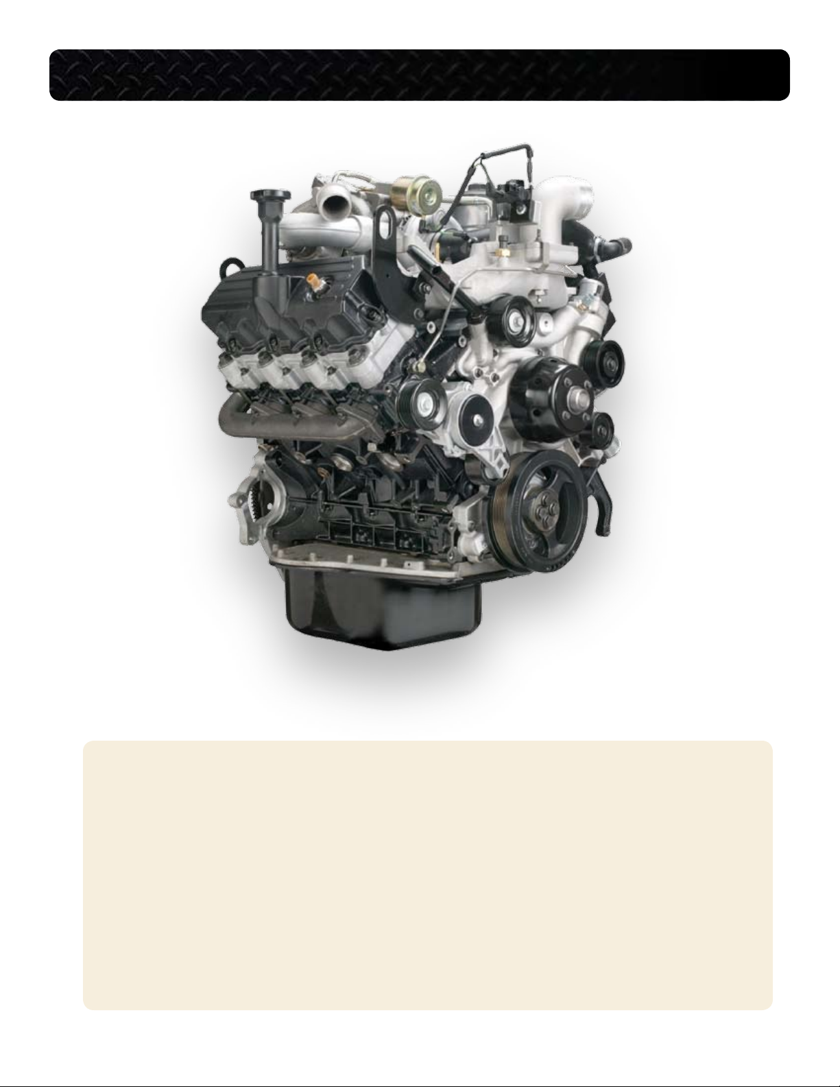
DIRECT INJECTION TURBOCHARGED DIESEL ENGINE
VT 275 FEATURES
90° V6
•
Offset Crankpins
•
Rear Gear Train
•
Primary Balancer
•
Regulated Two-Stage Turbocharging System
•
Four Valves per Cylinder
•
Cooled Exhaust Gas Recirculation
•
Electro-Hydraulic Generation 2 Fuel Injection System
•
Top Mounted Oil and Fuel Filters
•
International® VT 275 V6 Engine • Workhorse Chassis Applications • Revision 1.0 • © Copyright 2006 International Truck and Engine Corporation
5

VT 275 0VERVIEW
0
50
100
150
200
250
300
350
400
450
500
600
800
1000
1200
1400
1600
1800
2000
2200
2400
2600
2800
3000
3200
3400
3600
0
25
50
75
100
125
150
175
200
225
250
Torque (ft-lb)
Power (HP)
Engine Speed (RPM)
Load (ft-lb)
Power (HP)
Power & Torque Curve
VT 275 ENGINE SPECIFICATIONS
Engine Type . . . . . . . . . . . . . . . . . . . . . . . . . . . . . . . . . . . . . . . . 4-stroke, direct injection diesel
Configuration . . . . . . . . . . . . . . . . . . . . . . . . . . . . . V6, pushrod operated four valves / cylinder
Displacement . . . . . . . . . . . . . . . . . . . . . . . . . . . . . . . . . . . . . . . . . . . . . . . 275 cu. in. (4.5 liters)
Bore . . . . . . . . . . . . . . . . . . . . . . . . . . . . . . . . . . . . . . . . . . . . . . . . . . . . . . . . . . 3.74 in. (95 mm)
Stroke . . . . . . . . . . . . . . . . . . . . . . . . . . . . . . . . . . . . . . . . . . . . . . . . . . . . . . 4.134 in. (105 mm)
Compression Ratio . . . . . . . . . . . . . . . . . . . . . . . . . . . . . . . . . . . . . . . . . . . . . . . . . . . . . . . 18.0:1
Aspiration . . . . . . . . . . . . . . . . . . . . . . . . . . . . . . . . . Twin turbocharged and charge air cooled
Rated Power . . . . . . . . . . . . . . . . . . . . . . . . . . . . . . . . . . . . . . . . . . . . . . . . 200 hp @ 2700 rpm
Peak Torque . . . . . . . . . . . . . . . . . . . . . . . . . . . . . . . . . . . . . . . . . . . . . . . 440 lb-ft @ 1800 rpm
Engine Rotation, Facing the Flywheel . . . . . . . . . . . . . . . . . . . . . . . . . . . . . . Counterclockwise
Injection System . . . . . . . . . . . . . . . . . . . . . . . . . . Electro-hydraulic generation 2 fuel injection
Cooling Sysytem Capacity (Engine Only) . . . . . . . . . . . . . . . . . . . . . . . . . . . . . . . . . . 11 quarts
Lube System Capacity (Engine Only) . . . . . . . . . . . . . . . . . . . . . . . . . . 15 quarts with oil filter
Horsepower and Torque
The VT 275 engine is offered with only
one horsepower and torque rating for the
2005 model year. The engine creates 200
horsepower at 2700 rpm and 440 lb-ft
of torque at 1800 rpm. The engine has a
high idle speed of 2775 rpm with automatic transmission. The engine idle speed
is set at 700 rpm and is not adjustable.
6
International® VT 275 V6 Engine • Workhorse Chassis Applications • Revision 1.0 • © Copyright 2006 International Truck and Engine Corporation
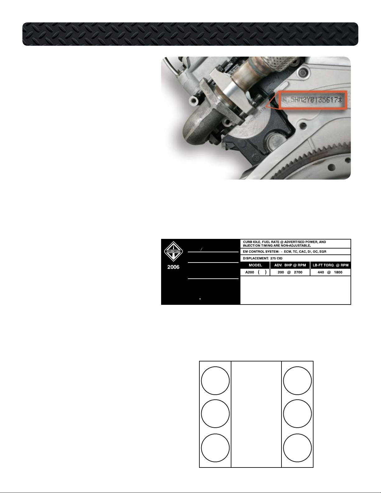
Engine Serial Number
VT 275 ENGINE FAMILY
6NVXH0275AEA
EMISSION CONTROL
INFORMATION
ENGINE MANUFACTURED BY:
INTERNATIONAL TRUCK
AND ENGINE CORPORATION
1870616C1
INTERNATIONAL
THIS ENGINE HAS A PRIMARY INTENDED SERVICE APPLICATION
AS A LIGHT HEAVY-DUTY DIESEL ENGINE AND CONFORMS TO
U.S. EPA , CANADIAN, AND AUSTRALIAN ADR-30 2006 MODEL
YEAR REGULATIONS. THE ENGINE IS ALSO CERTIFIED FOR
SALE IN CALIFORNIA IN NEW VEHICLES RATED ABOVE
14,000 POUNDS GVWR AND IS CERTIFIED TO OPERATE ON
DIESEL FUEL. THIS ENGINE IS OBD II EXEMPT.
TM
The Engine Serial Number (ESN) for the
VT 275 is located on a machined surface
at the left rear corner of the crankcase just
below the cylinder head.
The ESN identifies the engine family, the
build location, and the sequential
build number.
Engine Serial Number Example:
4.5HM2Y0135617
4.5 = Engine displacement
H = Diesel, Turbocharged
M2 = Motor Truck
Y = Huntsville
0135617 = Build Sequence
VT 275 OVERVIEW
Emissions Label
The Environmental Protection Agency
(EPA) emissions label is on top of the
breather, toward the front, on the left valve
cover. The label includes the following:
Advertised horsepower rating
•
Engine model code
•
Service application
•
Emission family and control system
•
Year the engine was certified to meet
•
EPA emission standards
Cylinder Numbering
The cylinders on the VT 275 are numbered from the front of the right bank 1, 3,
5 and from the front of the left bank 2, 4
and 6.
The engine firing order is 1-2-5-6-3-4
L Front R
2
1
4
6
International® VT 275 V6 Engine • Workhorse Chassis Applications • Revision 1.0 • © Copyright 2006 International Truck and Engine Corporation
3
5
7
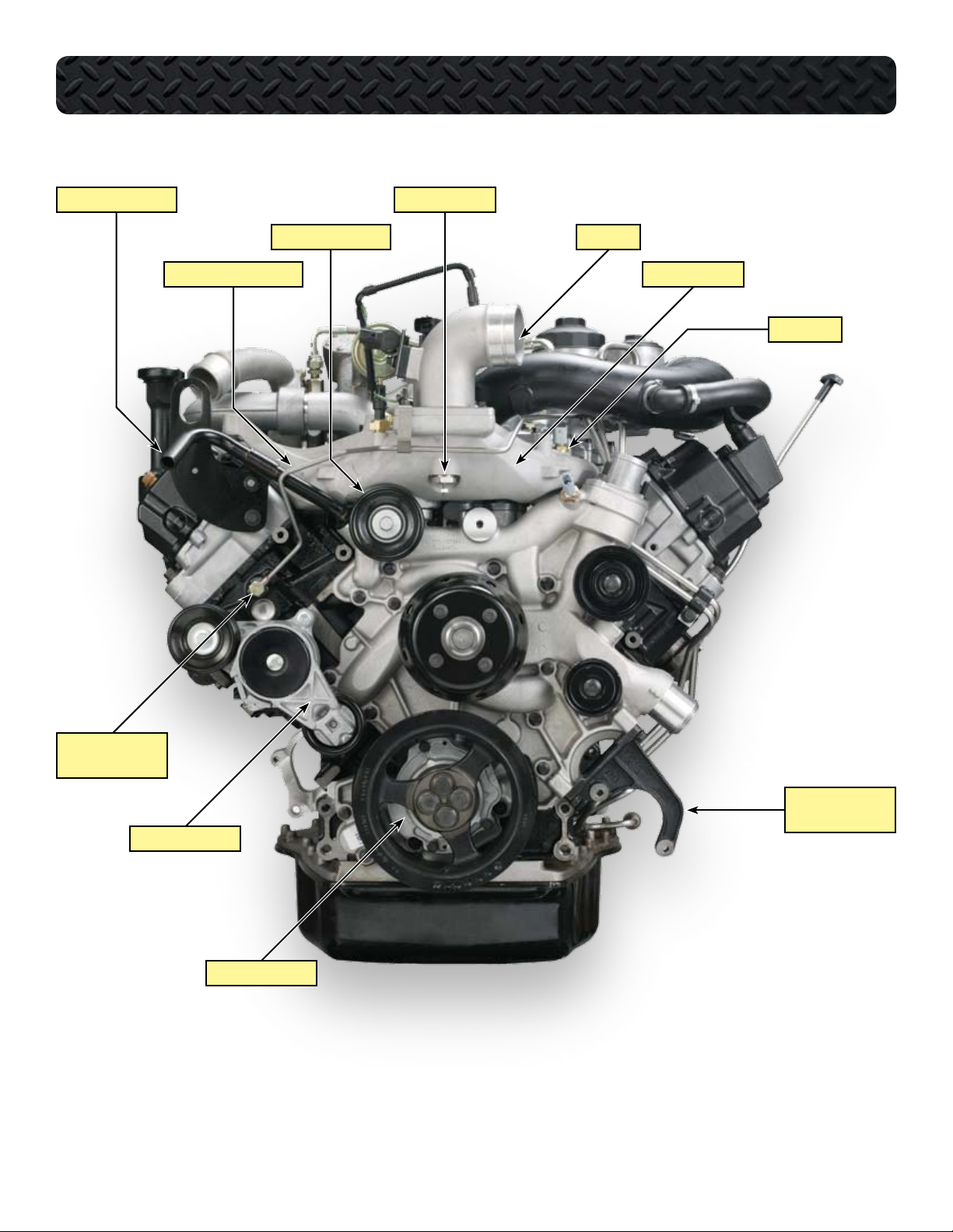
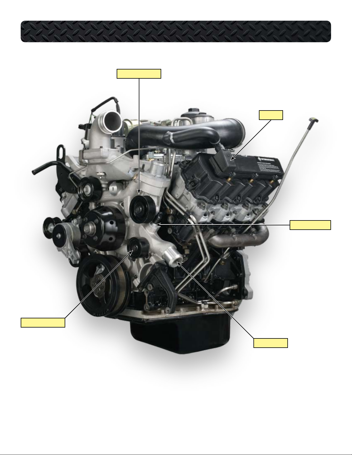
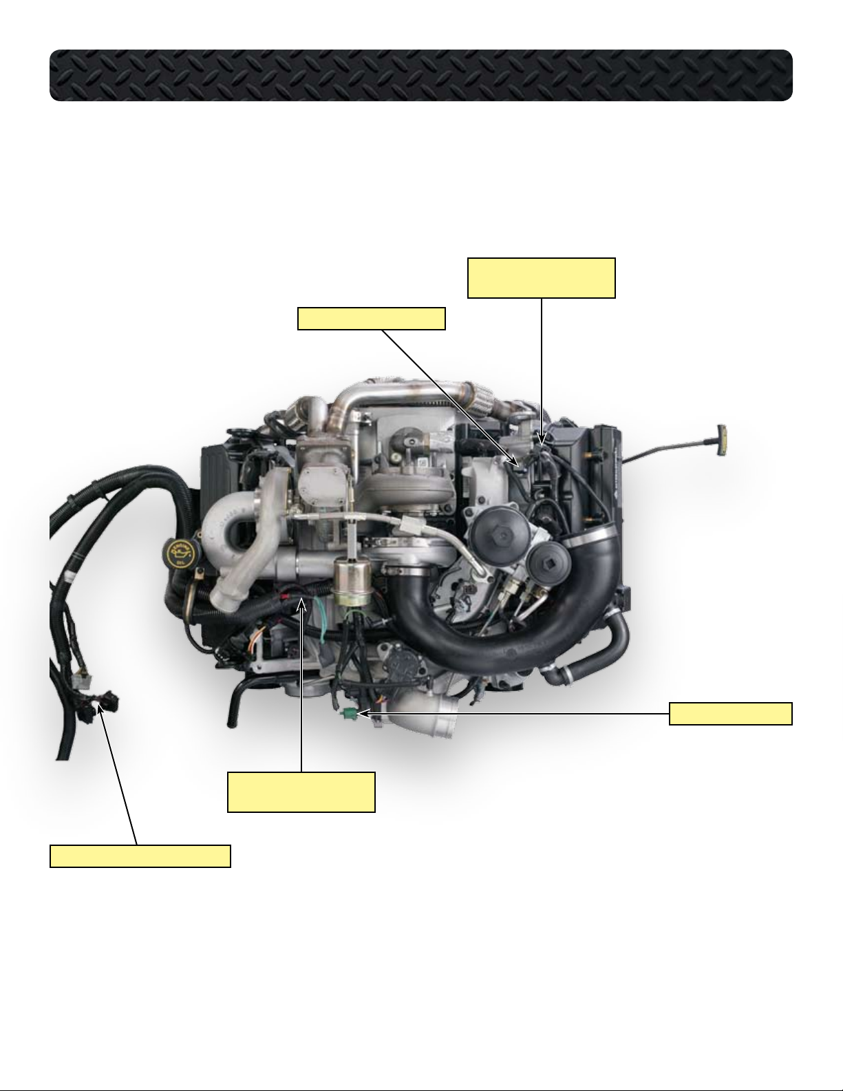
COMPONENT LOCATIONS - FRONT OF ENGINE
HEATER SUPPLY TUBE
FUEL TUBE TO RIGHT BANK
SMOOTH IDLER PULLEY
AIR INLET HEATER
AIR INLET
INTAKE MANIFOLD
MAT SENSOR
BANJO BOLT WITH
CHECK VALVE
POWER STEERING
PUMP BRACKET
BELT TENSIONER
OIL PUMP COVER
8
International® VT 275 V6 Engine • Workhorse Chassis Applications • Revision 1.0 • © Copyright 2006 International Truck and Engine Corporation
COMPONENT LOCATIONS - LEFT FRONT OF ENGINE
GROOVED IDLER PULLEY
BREATHER
SMOOTH IDLER PULLEY
HEATER RETURN TUBE
COOLANT OUTLET
International® VT 275 V6 Engine • Workhorse Chassis Applications • Revision 1.0 • © Copyright 2006 International Truck and Engine Corporation
9
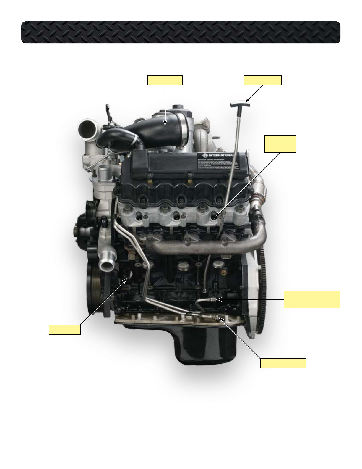
COMPONENT LOCATIONS - LEFT SIDE OF ENGINE
AIR INLET DUCT OIL LEVEL GAUGE
LEFT BANK
GLOW PLUGS
SUPPLY FROM FUEL PUMP
AND PRIMARY FILTER
CMP SENSOR
FUEL RETURN TO TANK
10
International® VT 275 V6 Engine • Workhorse Chassis Applications • Revision 1.0 • © Copyright 2006 International Truck and Engine Corporation
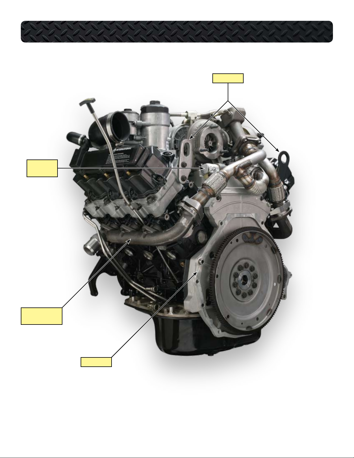
IPR AND
HEAT SHIELD
COMPONENT LOCATIONS - LEFT REAR OF ENGINE
LIFTING EYES
LEFT BANK
EXHAUST MANIFOLD
REAR COVER
International® VT 275 V6 Engine • Workhorse Chassis Applications • Revision 1.0 • © Copyright 2006 International Truck and Engine Corporation
11
COMPONENT LOCATIONS - REAR OF ENGINE
OIL FILTER HOUSING
FUEL FILTER HOUSING
TURBINE HOUSING EXHAUST TUBE ASSEMBLY
HIGH PRESSURE PUMP COVER
12
International® VT 275 V6 Engine • Workhorse Chassis Applications • Revision 1.0 • © Copyright 2006 International Truck and Engine Corporation
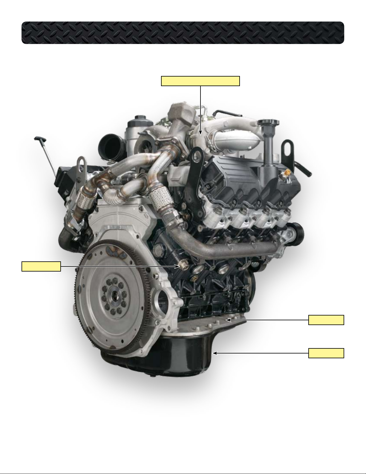
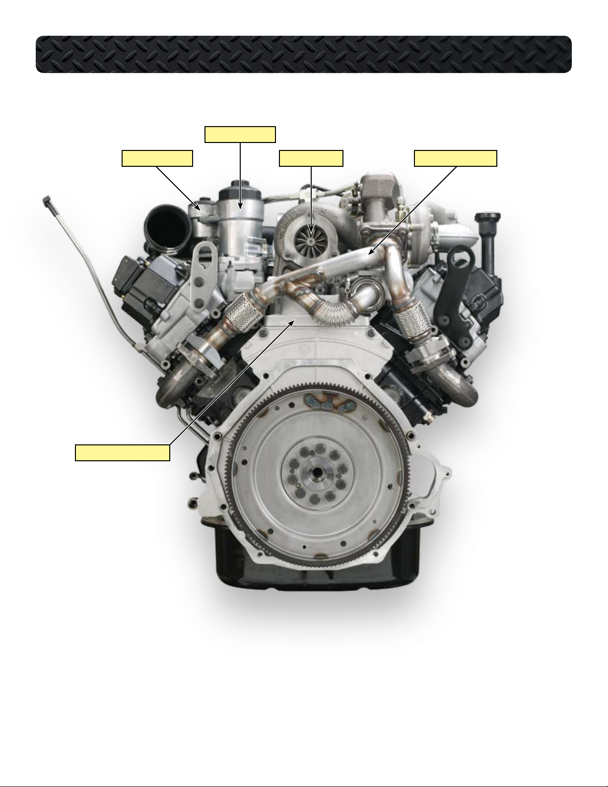
COMPONENT LOCATIONS - RIGHT REAR OF ENGINE
HIGH PRESSURE COMPRESSOR HOUSING
COOLANT HEATER
UPPER OIL PAN
LOWER OIL PAN
International® VT 275 V6 Engine • Workhorse Chassis Applications • Revision 1.0 • © Copyright 2006 International Truck and Engine Corporation
13
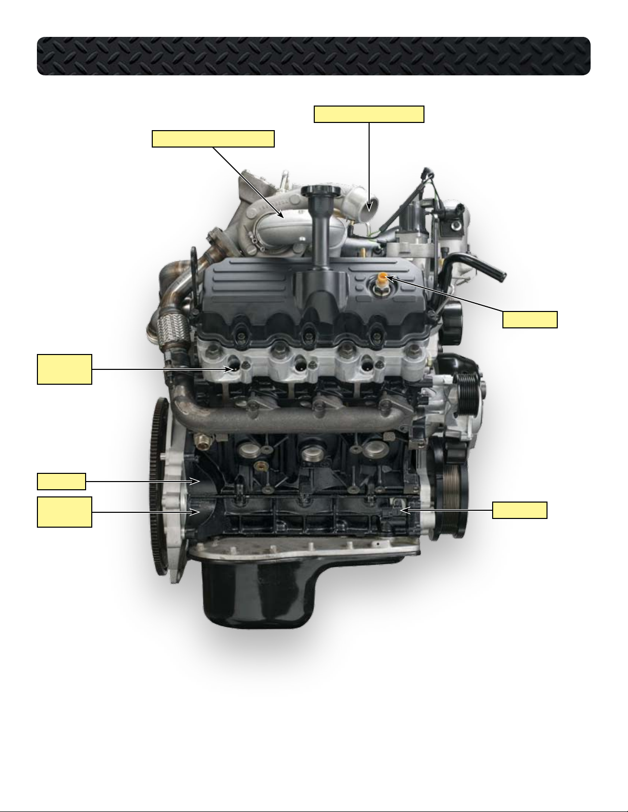
COMPONENT LOCATIONS - RIGHT SIDE OF ENGINE
OUTLET TO CHARGE AIR COOLER
TURBOCHARGER CROSSOVER TUBE
ICP SENSOR
RIGHT BANK
GLOW PLUGS
CRANKCASE
LOWER
CRANKCASE
CKP SENSOR
14
International® VT 275 V6 Engine • Workhorse Chassis Applications • Revision 1.0 • © Copyright 2006 International Truck and Engine Corporation
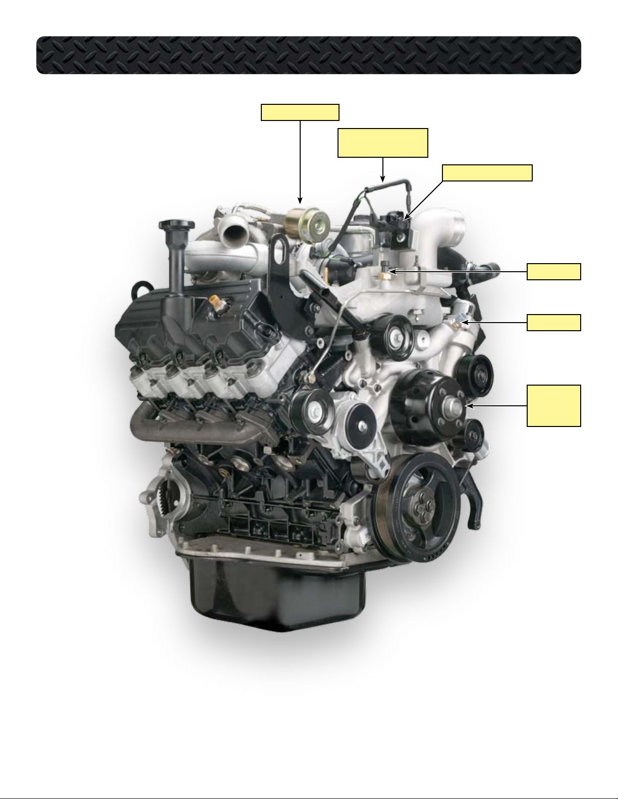
COMPONENT LOCATIONS - RIGHT FRONT OF ENGINE
PNEUMATIC ACTUATOR
BOOST CONTROL SOLENOID
HOSE HARNESS
BOOST CONTROL SOLENOID
MAP SENSOR
ECT SENSOR
WATER PUMP
PULLEY
AND FAN DRIVE
International® VT 275 V6 Engine • Workhorse Chassis Applications • Revision 1.0 • © Copyright 2006 International Truck and Engine Corporation
15
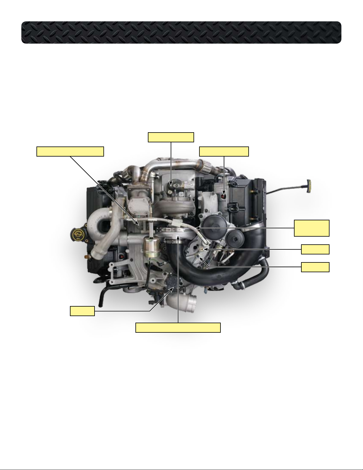
COMPONENT LOCATIONS - TOP OF ENGINE WITHOUT HARNESS
HIGH PRESSURE PUMP
HIGH PRESSURE TURBINE HOUSING
EGR VALVE
INJECTOR CONNECTORS
TURBOCHARGER
OIL SUPPLY LINE
EOP SWITCH
EOP SENSOR
LOW PRESSURE TURBO COMPRESSOR HOUSING
16
International® VT 275 V6 Engine • Workhorse Chassis Applications • Revision 1.0 • © Copyright 2006 International Truck and Engine Corporation
COMPONENT LOCATIONS - TOP OF ENGINE WITH HARNESS
MAF SENSOR CONNECTOR
(SENSOR NOT SHOWN)
INJECTOR HARNESS CONNECTOR
HARNESS TO CHASSIS-MOUNTED ECM/IDM
International® VT 275 V6 Engine • Workhorse Chassis Applications • Revision 1.0 • © Copyright 2006 International Truck and Engine Corporation
BOOST CONTROL SOLENOID
ALTERNATOR FUSIBLE LINKS
(ALTERNATOR NOT SHOWN)
17
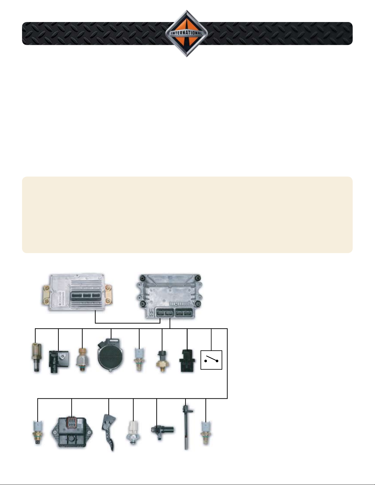
ELECTRONIC CONTROL
ECT
ECM
CKP
IDM
BAP
EOP
MAP
ICPIPR
EGR DRIVE
MODULE
BCS
MAF / IAT
EOT
MAT APS / IVS
CMP
ECL
SYSTEM
ECM and IDM control system
•
Dual magnetic pick-up timing sensors
•
Electric motor driven EGR valve
•
ECM boost control
•
System Features
The VT 275 eng i ne us e s the
•
Diamond Logic™ II Control System.
The electronic control system features
an Engine Control Module (ECM)
and an Injector Drive Module (IDM).
The Exhaust Gas Recirculation
•
(EGR) valve is positioned by an
ECM controlled electric stepper motor. The system uses an EGR drive
module to communicate commands
from the ECM to the EGR valve.
VT 275 engines use two magnetic
•
pickup sensors to determine crankshaft speed and position and camshaft
position. Magnetic pick-up sensors
feature high reliability and accuracy.
The VT 275 engine uses a twin turbo-
•
charger with ECM boost control.
18
International® VT 275 V6 Engine • Workhorse Chassis Applications • Revision 1.0 • © Copyright 2006 International Truck and Engine Corporation
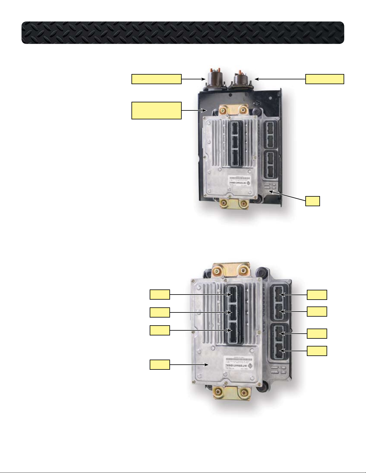
ECM
ELECTRONIC CONTROL SYSTEM
Th e EC M us es sen s or inp u ts to
•
control the Injection Pressure Regulator (IPR), the EGR valve, the boost
control solenoid, the glow plug relay
and the inlet air heater relay. The ECM
also shares sensor data with the IDM
over communication links between the
two modules.
• The IDM is mounted on brackets cast
into the ECM. The ECM and IDM are
then mounted with vibration isolator
grommets to the control module assembly bracket on the Power Distribution Center (PDC).
IDM
The Injector Drive Module (IDM) re-
•
ceives sensor information from the
ECM over three communication links:
the CAN 2 link, the CMPO circuit,
and the CKPO circuit. The IDM uses
this information to calculate injection
timing and duration. The IDM controls injector operation through 48volt signals to the twin injector coils.
INLET AIR HEATER RELAY GLOW PLUG RELAY
CONTROL MODULE
ASSEMBLY BRACKET
ECM
IDM X1
ECM X1
The ECM has four connectors. The
•
connectors are called X1 through X4
with ECM X1 being the top ECM connector as mounted on the truck. The
IDM has three connectors with IDM X1
being the top connector as mounted
on the truck. The ECM X1 and X2 connectors are for engine sensor inputs
and X3 and X4 are for chassis inputs.
The IDM X1 and X2 connectors are for
injector operation and X3 is for chassis
inputs and communication between
the ECM and IDM.
International® VT 275 V6 Engine • Workhorse Chassis Applications • Revision 1.0 • © Copyright 2006 International Truck and Engine Corporation
IDM X2
IDM X3
IDM
ECM X2
ECM X3
ECM X4
19
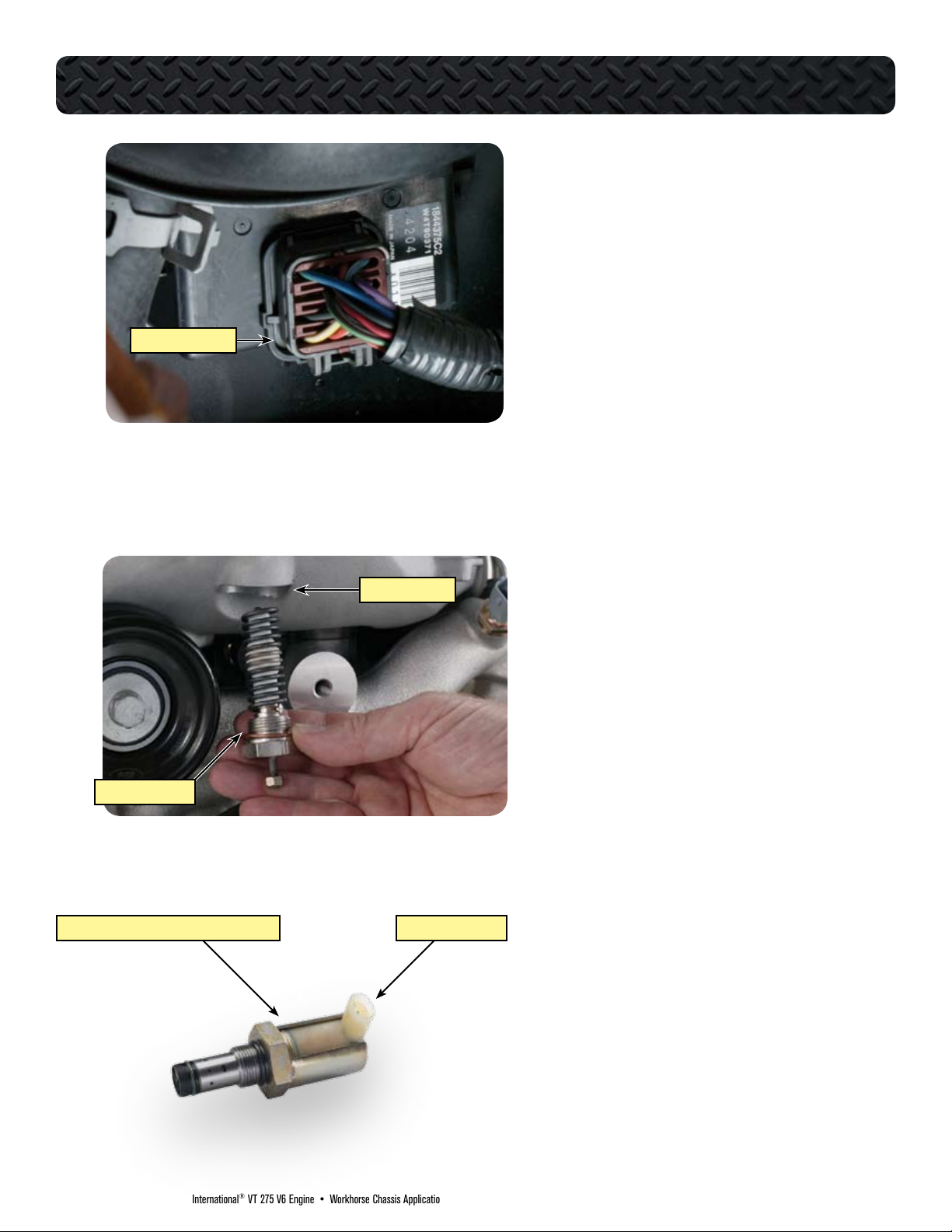
EGR DRIVE MODULE
ELECTRONIC CONTROL SYSTEM
EGR Drive Module
The EGR Drive Module receives the desired
•
EGR valve position from the ECM over the engine CAN 2 link. The module then sends a series
of voltage and ground signals to the Motor U, V,
and W terminals of the EGR valve. The voltage
signals are Pulse Width Modulated (PWM)
to control current flow to the motor field coils.
The module receives battery voltage and ground
•
through the 12-way engine-to-chassis connector. The module supplies a reference voltage to
three position sensors within the EGR valve.
The drive module uses the sensor signals to
determine the percent of valve opening.
INTAKE MANIFOLD
INLET AIR HEATER
INJECTION PRESSURE REGULATOR (IPR) VALVE SWIVEL CONNECTOR
Inlet Air Heater Element
The Inlet Air Heater element is located in the
•
lower side of the intake manifold and projects
through the manifold and into the inlet air stream.
The element warms the incoming air to aid
•
cold start and reduce emissions during warmup. The ECM turns the inlet air heater on for
a predetermined amount of time, based on
engine oil temperature, intake air temperature,
and barometric air pressure. The inlet air heater
can remain on while the engine is running to
reduce white smoke during engine warm-up.
Injection Pressure Regulator (IPR) Valve
The IPR mounts to the high-pressure pump
•
and controls the amount of oil allowed to drain
from the high-pressure system. When the ECM
increases the IPR signal duty cycle, the valve
blocks the oil’s path to drain and pressure rises.
When the ECM reduces the duty cycle, a larger
volume of oil is allowed to drain from the system
and pressure is reduced. The valve contains a
pressure relief valve for the system that opens
if system pressure reaches 4500 psi. The IPR
is protected by a heat shield that must be reinstalled after servicing.
20
International® VT 275 V6 Engine • Workhorse Chassis Applications • Revision 1.0 • © Copyright 2006 International Truck and Engine Corporation
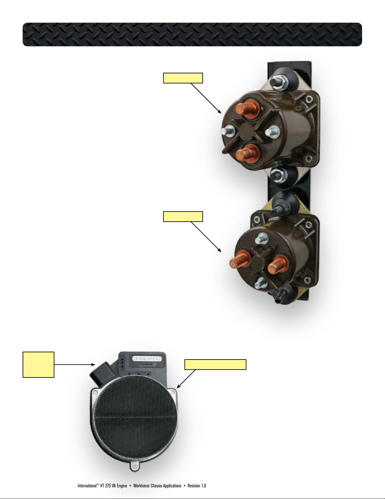
Inlet Air Heater Relay
The Inlet Air Heater (IAH) element is
•
used to improve cold start operation,
reduce emissions and white smoke,
and improve engine warm-up. The IAH
relay is the taller of the two relays. The
IAH relay receives battery power from
the starter power-feed terminal and the
normally open terminal connects to the
element through the harness. One end
of the relay coil is grounded through
the engine 12-way connector. The relay closes when the coil receives voltage from the ECM.
Glow Plug Relay
Glow plugs are used to improve cold
•
engine starting. Glow plug operation
is controlled by the ECM through the
glow plug relay. The relay common
terminal is connected by jumper to
the common terminal of the Inlet Air
Heater relay. The normally open terminal connects to the glow plug harness.
One end of the relay coil is grounded
through the engine 12-way connector.
The relay is closed when the other end
of the coil receives voltage from the
ECM.
ELECTRONIC CONTROL SYSTEM
AIR HEATER RELAY
GLOW PLUG RELAY
MAF / IAT
5-PIN
CONNECTOR
MASS AIR FLOW (MAF) SENSOR
Mass Air Flow (MAF) Sensor
The Mass Air Flow (MAF) sensor is
•
mounted with ductwork between the
turbocharger inlet and the air filter element. The sensor applies voltage to
a low resistance thermistor exposed
to the fresh air portion of the intake
charge. The MAF sensor circuitry measures the increase in voltage required
to offset the cooling effect of the air
flow over the thermistor. This voltage
is then converted into a variable frequency that is sent to the ECM. The
MAF value can be read with MasterDiagnostics® software in lb./min.
International® VT 275 V6 Engine • Workhorse Chassis Applications • Revision 1.0 • © Copyright 2006 International Truck and Engine Corporation
21
ELECTRONIC CONTROL SYSTEM
ECM
BATTERY
F-47
TO IDM RELAY
TO
ENGINE
INLINE
12-WAY
F38
R
PDC
1
STARTER
MOTOR
RELAY
KEY SWITCH
PDC#
F4
F12
F41
F46
R
Device
30A...IDM/ECM
20A...RU N/ACC
10A...ECM PWR
5A...ECM KEY PWR
ECM RELAY - POSITION 50
X1
X2
X3
X4
X1
X2
X3
X4
X3-3 VIGN
X3-5 ECM MPR
X4-1 ECM PWR
X4-2 ECM PWR
1
87
85
30
86
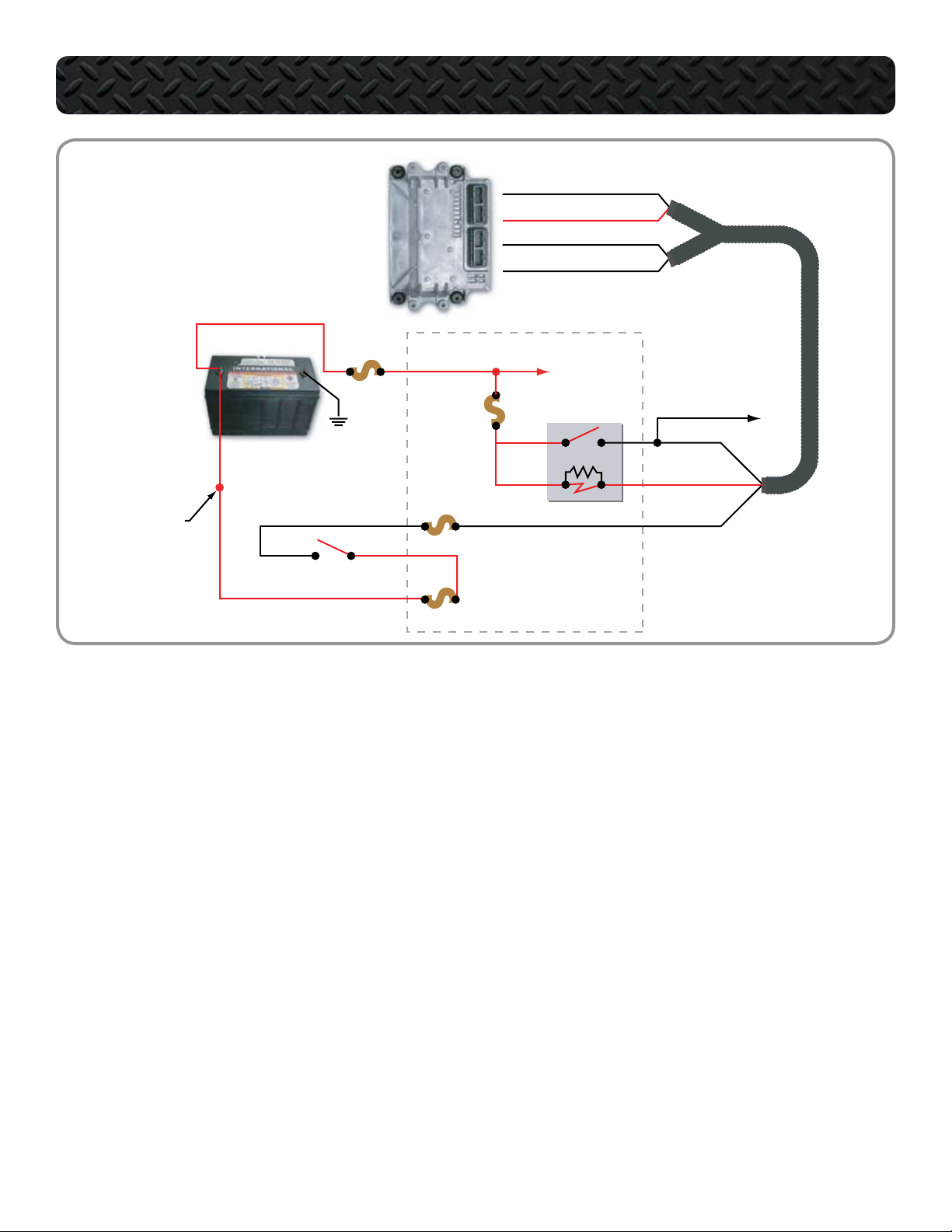
ECM Relay Circuit Operation
The ECM controls its own power up
•
and power down process. When the
key is OFF, the ECM stays powered up
for a brief period. The ECM then powers down after internal housekeeping functions have been completed.
Key Power
The Run/Accessory position of the
•
Key Switch receives battery voltage
from the Power Distribution Center.
When the key is ON, the switch supplies battery voltage through fuse
F47 to ECM pin X3-3. Battery voltage
is available at all times through fuse
F38 to ECM relay pins 30 and 86.
Pin 86 supplies voltage to the relay coil.
•
Pin 85 connects the coil to pin X3-5
•
of the ECM.
When the key is ON, voltage supplied
•
to pin X3-3 signals the ECM that the
operator is going to start the engine.
The ECM then supplies a ground
circuit to pin X3-5. When this occurs, current flows through the ECM
relay coil and creates a magnetic
field causing the relay to latch. When
latched, the relay connects pin 30
to pin 87 and supplies current to the
ECM through pin X4-1 and X4-2.
Shut Down
When the key is OFF and voltage is
•
removed from ECM pin X3-3, the ECM
shuts down the engine but keeps the
ECM powered up briefly until the internal house keeping is completed.
22
International® VT 275 V6 Engine • Workhorse Chassis Applications • Revision 1.0 • © Copyright 2006 International Truck and Engine Corporation
ECM Power Relay
ELECTRONIC CONTROL SYSTEM
DTC 112 Electrical system voltage B+ out-of-range high
The ECM detects an alternator output greater than 23 volts at
ECM Pin X3-3 for more than 0.5 seconds.
Possible causes: • Voltage increases
• Jump starting the engine
• Incorrect external battery connections
DTC 626 Unexpected reset fault
Set when power is interrupted to the ECM or causes an ECM
power down.
Possible causes: • Loose or dirty connections at battery
or ground cables
• Power feed wiring problems
• Low battery voltage
DTC 113 Electrical system voltage B+ out-of-range low
The ECM detects less than 7 volts at ECM Pin X3-3 for more
than 0.5 seconds.
Possible causes: • Discharged batteries
• Increased resistance in the battery feed
circuits
• Failed alternator or ECM power relay
Voltage Checks - ECM Power Relay Socket
Turn Key Switch OFF.
1.
Remove ECM relay and inspect for corroded terminals.
2.
Connect relay breakout harness to relay and socket.
3.
Measure voltage with Key Switch in the required test position.
4.
TEST POINT KEY SWITCH SPECIFICATION COMMENTS
85 to GND ON 0.06 to 2 V If greater than 2 volts, check for open or short to B+.•
85 to GND OFF
for open
86 to GND ON/OFF B+ If no voltage, check the fuse.
30 to GND ON B+ If no voltage, check the fuse.
87 to GND ON B+ If no voltage, check for failed relay.•
87 to GND OFF O V If greater than 0 volts, check for short to B+.•
B+ If no voltage, check the fuse.
•
If fuse is good, check for open.
•
•
If fuse is blown, check for short to ground.
•
If fuse is good, check for open.
•
•
If fuse is blown, check for short to ground.
•
If fuse is good, check for open.
•
If measurements are OK, send the vehicle to your International® dealer for further diagnostics.
International® VT 275 V6 Engine • Workhorse Chassis Applications • Revision 1.0 • © Copyright 2006 International Truck and Engine Corporation
23

ELECTRONIC CONTROL SYSTEM
BATTERY
F34
F-47
TO IDM RELAY
R
PDC
F66
2
STARTER
MOTOR
RELAY
KEY SWITCH
12
6
8
9
ENGINE IN-LINE
12-WAY
30 87
86 85
IDM
X1
X2
X3
X1
X2
X3
X3-8 IDM LOGIC POWE R
X3-24 IDM MAIN POWER
X3-25 IDM MAIN POWE R
X3-4 IDM MAIN POWER
X3-23 IDM MAIN POWER
X3-27 IDM M PR
X3-7 VIGN
IDM Relay Circuit Operation
The IDM controls its own power up
•
and power down process. When the
key is OFF, the IDM stays powered up
for a brief period. The IDM then powers down after internal housekeeping functions have been completed.
IDM Power Up
The Key Switch receives battery volt-
•
age from the Power Distribution Center
(PDC. When the key is ON, the switch
supplies battery voltage through F-47
fuse and pin 9 of the engine 12-way
connector to pin X3-7 of the IDM.
Battery voltage is available through
•
the PDC F-34 fuse to IDM relay pin
30 and 86 at all times. Pin 85 supplies
voltage to the relay coil. Pin 85 takes
that voltage through pin 8 of the engine 12-way connector to pin X3-27
of the IDM. When the key is ON, voltage supplied to pin X3-7 signals the
IDM to provide a ground circuit to pin
X3-27. When this occurs, current flow-
24
International® VT 275 V6 Engine • Workhorse Chassis Applications • Revision 1.0 • © Copyright 2006 International Truck and Engine Corporation
ing through the IDM relay coil builds
a magnetic field that causes the relay
to latch. When latched, the relay connects pin 30 to pin 87 and supplies
current through pin 12 of the engine
in-line 12-way connector to pin X3-4,
X3-23, X3-24, and X3-25 of the IDM.
Four pins receive voltage to spread
the current draw over multiple pins.
IDM Logic
The IDM also requires voltage for the
•
internal logic circuit. When the IDM relay latches, pin 87 of the relay supplies
voltage to the IDM logic circuit through
fuse F-66 in the PDC. The fuse feeds
through pin 6 of the engine in-line 12way connector to the IDM pin X3-8.

ELECTRONIC CONTROL SYSTEM
IDM Power Relay
DTC 523 IDM Vign Voltage Low
The ECM detects voltage from VIGN less than 7 volts.
Possible causes: • Connections between the IDM Pin X3-7 and the VIGN
DTC 525 IDM fault
The ECM detects an internal IDM failure.
DTC 533 IDM relay voltage high
The ECM detects voltage from the IDM power relay greater than 16 volts.
Possible causes: • When jump starting the engine
• Incorrect external battery connections
• Alternator voltage output of 16 volts or more
DTC 534 IDM relay voltage low
The ECM detects voltage from the IDM power relay less than 7 volts.
Possible causes: • Discharged batteries
• Increased resistance in the battery feed circuits
• Failed IDM power relay or alternator
Voltage Checks - IDM Power Relay Socket
Turn Key Switch OFF.
1.
Remove IDM relay and inspect for corroded terminals.
2.
Connect relay breakout harness to relay and socket.
3.
Measure voltage with Key Switch in required test position.
4.
TEST POINT KEY SWITCH SPECIFICATION COMMENTS
86 to gnd ON 0.06 to 2 V If greater than 2 volts, check for open or short to B+.•
86 to gnd OFF B+ If no voltage, check the fuse. If fuse is good, check for open.•
85 to gnd ON / OFF B+ If no voltage, check the fuse.
30 to gnd ON B+ If no voltage, check the fuse.
87 to gnd ON B+ If no voltage, check for failed relay.•
87 to gnd OFF 0 V If greater than 0 volts, check for short to B+•
•
If fuse is blown, check for short to ground.
•
If fuse is good, check for open.
•
•
If fuse is blown, check for short to ground.
•
If fuse is good, check for open.
•
CONTINUED ON THE NEXT PAGE Ñ
International® VT 275 V6 Engine • Workhorse Chassis Applications • Revision 1.0 • © Copyright 2006 International Truck and Engine Corporation
25

ELECTRONIC CONTROL SYSTEM
IDM Power Relay CONTINUED
Voltage Checks - 12-pin Connector
Turn Key Switch OFF.
1.
Remove 12-pin connector.
2.
Inspect for bent pins or corrosion.
3.
Connect 12-pin breakout harness to chassis harness.
4.
Turn Key Switch to the ON position.
5.
TEST POINT SPECIFICATION COMMENTS
9 to gnd B+ If no voltage, check the fuse.
8 to gnd 0.06 to 2 V If greater than 2 volts, check for open.•
12 to gnd B+ If no voltage, check for short to ground or open.•
6 to gnd B+ If no voltage, check fuse.
1 to gnd 0 V If greater than 0 volts, check for open or high resistance (voltage readings indicate
•
If fuse is blown, check for short to ground.
•
If fuse is good, check for open.
•
•
If fuse is blown, check for short to ground.
•
If fuse is good, check for open.
•
•
poor ground to battery).
Harness Resistance Checks
Turn Key Switch OFF.
1.
Remove IDM relay and inspect for corroded terminals.
2.
Install relay breakout harness to socket only.
3.
Disconnect positive battery cable.
4.
Use disconnected positive battery cable for B+ test point.
5.
TEST POINT SPECIFICATION COMMENTS
30 to B+ cable < 5 Ω If greater than 5 Ω, check fuses.
86 to B+ cable < 5 Ω If greater than 5 Ω, check fuses.
•
If fuses are good, check for open.
•
•
If fuses are good, check for open.
•
26
International® VT 275 V6 Engine • Workhorse Chassis Applications • Revision 1.0 • © Copyright 2006 International Truck and Engine Corporation

ELECTRONIC CONTROL SYSTEM
ECM
BATTERY
200 A
IAH
RELAY
GLOW PLUG
RELAY
GPC
GPD
GLOW PLUGS
ECT
STARTER IAH
BAP
X1-17 GPC
X1-21 GPD
2 4 6
1 3 5
4
12-WAY
ENGINE TO CHASSIS
CON NECTOR
N.O. TERM INAL
X1
X2
X3
X4
X1
X2
X3
X4
Glow Plug System
The VT 275 uses glow plugs to aid
•
cold starts. The ECM turns on the
glow plugs prior to engine cranking to
increase the temperature of the cylinders. Glow plug operation is controlled
by the ECM through the glow plug relay. The glow plugs have full voltage
if battery voltage is normal, or pulse
width modulated to control the current if battery voltage is above normal.
The ECM calculates glow plug ontime
based on coolant temperature and
barometric pressure. The required time
to warm up the cylinders decreases as
engine coolant temperature increases.
Warm up time decreases as barometric air pressure increases. The glow
plugs may continue to be energized
after start-up to reduce emissions.
Relay Operation
The glow plug relay receives battery
•
voltage to its common terminal from
the starter power-feed terminal. The
normally open terminal connects to
the individual glow plugs through the
glow plug harness. One end of the
relay coil is always grounded through
pin 4 of the engine 12-way connector.
The ECM supplies 12 volts to the other
end of the coil through ECM pin X117 in order to close the relay contacts.
Glow Plug Lamp
The glow plug lamp is used as a
•
wait-to-start indicator. The ECM
lights the glow plug lamp at glow
plug activation to signal the operator
to wait for the cylinders to warm up.
Both lamp operation and the glow plug
•
operation are based on BAP and ECT
values but are independent of each other.
The glow plug operation may
•
continue after the lamp is off.
Glow Plug Diagnostics
Glow plug diagnostics are used to
•
determine if the relay is operating cor-
rectly when commanded on. An additional wire on the relay’s normally
open terminal connects to ECM pin
X1-21. This circuit, GPD, allows the
ECM to monitor the relay operation.
The glow plugs can be turned on using
•
the KOEO Glow Plug/Inlet Air Heater
Test. The test can only be activated
twice per key cycle.
International® VT 275 V6 Engine • Workhorse Chassis Applications • Revision 1.0 • © Copyright 2006 International Truck and Engine Corporation
27

GPC (Glow Plug Control) Circuit
ELECTRONIC CONTROL SYSTEM
DTC 251 Glow Plug Control OCC self-test failed
Key On Engine Off Standard Test detects a fault in the glow
plug relay control circuit.
Possible causes: • Open or short in GPC signal circuit
• Open in actuator power ground
• Open glow plug relay coil
DTC 375 Glow Plug Relay Circuit Fault
The ECM does not see the expected relay output voltage
value.
Possible causes: • Open in the B+ supply circuit to glow
plug relay
• Open or short in GPC circuit
• Failed glow plug relay
Note: If DTC 251 and DTC 375 are both set, repair DTC 251
Voltage Checks - Relay
first.
Measure voltage with Key Switch in the required test position (on-time is temperature dependent).
TEST POINT KEY SWITCH SPECIFICATION COMMENTS
GP relay control
terminal to GND
GP relay control
terminal to GND
Actuator Pwr
Gnd to gnd
GP battery sup-
ply terminal to
gnd
GP relay output
terminal to gnd
GP relay output
terminal to gnd
ON B+ If no voltage, check for short to ground or open.•
OFF 0 V If greater than 0 V, check for short to power.•
OFF 0 V If greater than 0 V, check for open.•
ON B+ If no voltage, check the fuse.
ON B+ If no voltage, check for failed relay.•
OFF 0 V If greater than 0 volts, check for short to B+ or check for failed
•
If fuse is blown, check for short to ground.
•
If fuse is good, check for open
•
•
relay
28
International® VT 275 V6 Engine • Workhorse Chassis Applications • Revision 1.0 • © Copyright 2006 International Truck and Engine Corporation

ELECTRONIC CONTROL SYSTEM
ECM
BATTERY
200 A
IAHC
IAHD
MAF / IAT
IAH
RELAY
EOT
STARTER IAH
BAP
X1-18 IAHC
X2-11 IAHD
N.O. TERM INAL
4
12-WAY
ENGINE TO CHASSIS
CON NECTOR
X1
X2
X3
X4
X1
X2
X3
X4
Inlet Air Heater Operation
The VT 275 has an Inlet Air Heater
•
(IAH) element mounted in the front of
the intake manifold. The IAH is used to
improve cold start operation, reduce
emissions and white smoke, and improve engine warm-up. When the key
is ON, the ECM determines if the element should be activated and for how
long, based on barometric pressure
and engine oil temperature. On time
is limited to prevent heater element
damage and to prevent damage to the
intake manifold. The heater relay delivers full voltage to the element if battery voltage is normal, or the relay is
pulsed by the ECM to control the current if battery voltage is above normal.
If the battery voltage is so low that
the starter motor operation may be affected, the inlet air heater is disabled.
Relay Operation
The IAH relay receives battery power
•
from the starter power feed terminal.
The normally open terminal connects
to the element through the harness.
One end of the relay coil is always
grounded through pin 4 of the engine
12-way connector. The other end of
the coil receives 12 volts from ECM
pin X1-18 to close the relay contacts.
Inlet Air Heater Diagnostics
An additional wire on the normally
•
open terminal connects to ECM pin
X2-11. This diagnostic circuit allows
the ECM to determine if the IAH relay is
on when commanded on by the ECM.
The Inlet Air Heater can be turned on
•
using the KOEO Glow Plug/Inlet Air
Heater Test. The test can only be activated twice per key cycle. The ECM
will delay the Inlet Air Heater operation
for three seconds after the test is activated.
International® VT 275 V6 Engine • Workhorse Chassis Applications • Revision 1.0 • © Copyright 2006 International Truck and Engine Corporation
29

IAH (Inlet Air Heater) Circuit
ELECTRONIC CONTROL SYSTEM
DTC 238 Inlet Air Heater Control OCC self-test failed
Key On Engine Off Standard test detects a fault in the inlet air
heater control circuit.
Possible causes: • Open or short in IAHC circuit
• Open in actuator power ground
• Open inlet in air heater relay coil
DTC 373 Inlet Air Heater relay circuit fault
The ECM does not see the expected relay output voltage
value.
Possible causes: • Open in the B+ supply circuit to inlet air
heater relay
• Open or short in IAH control circuit
• Failed inlet air heater relay
Note: If DTC 238 and DTC 373 are both set, repair DTC 238
Voltage Checks - Relay
first.
Measure voltage with Key Switch in the required test position (on-time is temperature dependent).
TEST POINT KEY SWITCH SPECIFICATION COMMENTS
IAH relay control
terminal to gnd
IAH relay control
terminal to gnd
Actuator Pwr
Gnd to gnd
IAH battery sup-
ply terminal to
gnd
IAH relay output
terminal to gnd
IAH relay output
terminal to gnd
ON B+ If no voltage, check for short to ground or open.•
OFF 0 V If greater than 0 V, check for short to power.•
ON 0 V If greater than 0 V, check for open.•
ON B+ If no voltage, check the fuse.
ON B+ If no voltage, check for failed relay.•
OFF 0 V If greater than 0 volts, check for short to B+ or check for failed
•
If fuse is blown, check for short to ground.
•
If fuse is good, check for open
•
•
relay
30
International® VT 275 V6 Engine • Workhorse Chassis Applications • Revision 1.0 • © Copyright 2006 International Truck and Engine Corporation

ELECTRONIC CONTROL SYSTEM
IDM
ECM
X1
X2
X3
X4
E D C B A
MAF / IAT
EGR
DRIVE
MODULE
BCS
IPR
EGR
VALVE
RIGHT BANK INJECTORS
X1-7 IAT
X1-6 IAT SIG GRD
X2-2 MAF
LEFT BANK INJECTORS
FIXED
RESISTOR
HEATED
ELEM ENT
FIXED
RESISTOR
THER MISTO R
MAF
ECM
VREF
SIG
GRD
MICROPROC ESSOR
4
9
ENGINE
IN-LINE 12-WAY
CON NECTOR
ACT GRD
KEY PWR
MAF SIGNAL
KEY POWER
ACTUATOR GR D
SIGNAL GRD
IAT
B+
B+
SIGNAL
CONTROL
X1
X2
X3
X1
X2
X3
Mass Air Flow (MAF) Sensor
The MAF sensor is used to measure
•
the mass of the fresh air portion of the
intake air charge. To reduce Oxides of
Nitrogen (NOx), a portion of the fresh
air charge is displaced with cooled
exhaust gases. The ECM calculates
the total engine gas flow based on
MAT, MAP and RPM. The ECM then
determines the required EGR percent based on the current engine
operating conditions. At this point,
the ECM commands the exhaust portion of the total charge through the
EGR valve while monitoring the fresh
air portion through the MAF sensor.
Sensor Construction
The sensor housing contains two
•
sensors, the MAF sensor and the Intake Air Temperature (IAT) sensor.
The MAF sensor contains a heated
element placed in the air stream. The
amount of electrical power needed
to maintain the element at the proper
temperature depends directly on the
International® VT 275 V6 Engine • Workhorse Chassis Applications • Revision 1.0 • © Copyright 2006 International Truck and Engine Corporation
mass of air moving over the element.
Sensor Operation
The MAF sensor is made up of two
•
voltage divider circuits. A thermistor
and a fixed resistor make up one voltage divider circuit, and the heated element and a fixed resistor make up the
other voltage divider circuit. The two
voltage divider circuits are combined
into a bridge circuit with a common
power supply and a common ground.
During operation, when voltage is ap-
•
plied to the bridge, the temperature
of the heated element increases and
the resistance decreases. This affects the output of the divider circuit.
The thermistor side is affected only
•
by ambient air temperature. The divider voltages are compared and
the input voltage to the bridge
is increased or decreased until both divider voltages are equal.
An increase or decrease in air-
•
flow will change the ratio between
the divider voltages, which results
in a change to the supply voltage.
The signal controller circuit measures
•
the voltage to the bridge and, based
on that value, sends a frequency signal
to the ECM.
31

MAF (Mass Air Flow) Sensor
ELECTRONIC CONTROL SYSTEM
DTC 148 MAF signal frequency out of range low
The ECM detects MAF frequency less than 200 Hz for 5
seconds.
Possible causes: • Open or short to ground in the MAF
signal circuit
• Open in VIGN circuit
• Open in ground circuit
• Failed MAF sensor
DTC 149 MAF signal frequency out of range high
The ECM detects MAF frequency more than 11,500 Hz for 5
seconds.
Possible causes: • Short to voltage in the MAF signal
circuit
• Failed MAF sensor
Voltage Checks - 12-Pin Connector
DTC 166 Mass air flow sensor in-range fault
The ECM detects MAF reading is above 20 gps at key-on-engine-off, MAF is not reading 15 +/- 5 gps at low idle (in Park
or Neutral), or MAF is not reading 25 +/- 5 gps at low idle (in
Drive).
Possible causes: • Biased MAF/IAT sensor
• Plugged or leaking air intake or air filter
• Plugged exhaust system
DTC 167 Excessive mass air flow
The ECM detects MAF readings above a calibrated set point
based on engine rpm. MAF signal will be restricted to 300
gps.
Possible causes: • Biased or disconnected MAF/IAT
sensor
• Short to voltage in the MAF signal
circuit
Turn Key Switch to OFF.
1.
Disconnect the 12-Pin connector.
2.
Inspect for bent pins or corrosion.
3.
Connect 12-pin breakout harness.
4.
Disconnect negative battery cable. Use negative battery cable as the ground test point.
5.
Turn Key Switch to the ON position.
6.
TEST POINT SPECIFICATION COMMENTS
Pin 4 (12pin) to
gnd
Pin 9 (12pin) to
gnd
0 V If greater than 0 volts, check for open.•
B+ If less than B+, check for short to ground or open.•
32
International® VT 275 V6 Engine • Workhorse Chassis Applications • Revision 1.0 • © Copyright 2006 International Truck and Engine Corporation

ELECTRONIC CONTROL SYSTEM
ECM
BATTERY
F40
F65
HFCM
PDC
FUEL
PUMP
RELAY
TO
RUN / ACC
RELAY
X3-9 FPC
X4-15 FPM
X3-1 WIF
GRD
PUMP
HEATER
1
2
2
1
2
1
30
85
86 87
X1
X2
X3
X4
X1
X2
X3
X4
PDC#
F11
F19
Device
20A...FUEL PUMP
20A...FUEL HEATER
KEY SWITCH
F28
Pump Operation
The VT 275 has an ECM controlled
•
chassis mounted electric fuel pump. At
key-on, the ECM will operate the fuel
pump for up to 60 seconds to prime
the system. Priming allows the pump to
pressurize the system and to allow air in
the system to bleed out through an orifice between the filter housing and the
fuel return circuit. When the engine is
in run mode, the pump will operate continuously. If the engine dies or is shut
down, or if it is not started within 60
seconds, the ECM will stop the pump.
Circuit Operation
To operate the pump, the ECM provides
•
a ground at ECM pin X3-9 to latch the
fuel pump relay. The relay takes power
from fuse F40 and provides it to pin 1
of the pump connector. The ECM monitors the relay’s operation through ECM
pin X4-15. Battery voltage should be
present at X4-15 when the relay is commanded on. If the ECM does not detect the voltage, a DTC will be logged.
International® VT 275 V6 Engine • Workhorse Chassis Applications • Revision 1.0 • © Copyright 2006 International Truck and Engine Corporation
Fuel Heater
The Horizontal Fuel Conditioning Mod-
•
ule (HFCM) contains a fuel heater.
When the key is ON, the key switch
provides power to pin 1 of the heater connector through fuse 65. The
heater element contains a thermostat
that controls the heater operation.
Water-In-Fuel Sensor
The pump module contains a Water-
•
In-Fuel (WIF) sensor. The WIF sensor
receives voltage from fuse 65. If the
filter detects water, the sensor sends
the voltage to ECM pin X3-1. The ECM
then activates the dash WIF lamp.
Engine Coolant Level
The Engine Coolant Level (ECL) sen-
•
sor uses a floating ball and a magnetic
switch. When the coolant level is full,
the float will rise and the magnet will
pull the ECL contacts open. When
the level falls, the contacts close.
ECM Pin X3-4 supplies a 5v signal to
•
pin A of the ECL sensor. Pin B of the
sensor connector is grounded through
the chassis harness. When the level is
OK, the switch is open and the ECM
will see five volts on the circuit. If the
level is low, the switch is closed and
the circuit is grounded. With the circuit
grounded the voltage goes to zero.
The ECM can not detect an open or
•
short circuit in the ECL system but
does continuously monitors the circuit
for in-range faults. When the ECM detects a voltage between 3.4 and 4.3 it
is assumed there is a circuit failure and
an in-range fault, DTC 236 will be set.
This failure can be caused by a high resistance connection or an intermittent
short to ground.
33

ELECTRONIC CONTROL SYSTEM
HFCM (Horizontal Fuel Conditioning Module) Fuel Pump
DTC 237 Fuel Pump Control OCC self-test failed
Key On Engine Off Standard Test detects a fault in the fuel
pump relay control circuit.
Possible causes: • Open or short to ground on FPC circuit
• Open or short to ground on VIGN
circuit to the fuel pump relay
• Open fuel pump relay coil
DTC 374 Fuel Pump Relay Circuit failed
The ECM does not see the expected relay output voltage
value.
Possible causes: • Open in the B+ supply circuit to fuel
pump relay
• Open or shorted FPC circuit
• Failed fuel pump relay
Note: If DTC 237 and DTC 374 are both set, repair DTC 237
first.
Voltage Checks - Relay
Turn Key Switch OFF.
1.
Remove fuel pump relay and inspect for corrosion.
2.
Connect relay breakout harness to relay and socket.
3.
Measure voltage with Key Switch in the required test position (pump on-time is 60 seconds).
4.
TEST POINT KEY SWITCH SPECIFICATION COMMENTS
85 to gnd ON 0 to 0.25 V If greater than 0.25 volts, check for open or short to B+.•
85 to gnd OFF 0 V If greater than 0 volts, check for short to B+.•
86 to gnd ON B+ If no voltage, check the fuse.
30 to gnd ON B+ If no voltage, check the fuse.
87 to gnd ON B+ If no voltage, check for failed relay.•
87 to gnd OFF 0 V If greater than 0 volts, check for short to B+•
•
If fuse is blown, check for short to ground.
•
If fuse is good, check for open.
•
•
If fuse is blown, check for short to ground.
•
If fuse is good, check for open
•
Harness Resistance Checks - Relay to Ground
Turn Key Switch to OFF.
1.
Remove fuel pump relay and inspect for corrosion.
2.
Connect relay breakout harness to the socket only.
3.
Disconnect negative battery cable. Use disconnected negative battery cable for ground test point.
4.
TEST POINT SPECIFICATION COMMENTS
85 to gnd > 1 kΩ If less than 1 kΩ, check for short to ground.•
86 to gnd > 1 kΩ If less than 1 kΩ, check for blown fuse or short to ground.
30 to gnd > 1 kΩ If less than 1 kΩ, check for blown fuse or short to ground.•
87 to gnd > 1 kΩ If less than 1 kΩ, check for blown fuse or short to ground.•
34
International® VT 275 V6 Engine • Workhorse Chassis Applications • Revision 1.0 • © Copyright 2006 International Truck and Engine Corporation
•
Note: If Key Switch is grounded when Key Switch OFF this will be less than 5 Ω.
•
CONTINUED ON THE NEXT PAGE Ñ

ELECTRONIC CONTROL SYSTEM
HFCM (Horizontal Fuel Conditioning Module) Fuel Pump CONTINUED
Harness Resistance Checks - Relay to VIGN
Turn Key Switch to OFF.
1.
Remove fuel pump relay and inspect for corrosion.
2.
Connect relay breakout harness to the socket only.
3.
Disconnect negative battery cable. Use disconnected negative battery cable for ground test point.
4.
TEST POINT SPECIFICATION COMMENTS
86 to VIGN < 5 Ω If greater than 5 Ω, check VIGN and fuses, if OK check for open.•
Harness Resistance Checks - Relay to Pump
Turn Key Switch to OFF.
1.
Disconnect fuel pump connector.
2.
Inspect for bent pins or corrosion.
3.
Remove fuel pump relay and connect relay breakout harness to socket only.
4.
TEST POINT SPECIFICATION COMMENTS
87 to Pin 1 < 5 Ω If greater than 5 Ω, check for open.•
Harness Resistance Checks - Fuel Pump Connector to Ground
Turn Key Switch to OFF.
1.
Disconnect fuel pump connector.
2.
Inspect for bent pins or corrosion.
3.
Disconnect negative battery cable. Use disconnected negative battery cable for ground test point.
4.
TEST POINT SPECIFICATION COMMENTS
Pin 1 to gnd > 1 kΩ If less than 1 kΩ, check for short to ground.•
Pin 2 to gnd < 5 Ω If greater than 5 Ω, check for open.•
International® VT 275 V6 Engine • Workhorse Chassis Applications • Revision 1.0 • © Copyright 2006 International Truck and Engine Corporation
35

ELECTRONIC CONTROL SYSTEM
ECM
APS / IVS
IN CAB C RUI SE SWITCHES
TO RELAY 10
(RUN / CRANK)
BAP
IDM
EGR
DRIVE
MODULE
BCS
IPR
EGR
VALVE
RIGHT BANK INJECTORS
LEFT BANK INJECTORS
E
K
D
G
J
PDC
X4-6 COO
X3-14 RAS
X3-21 SCS
X3-24 BAP
X4-18 APS
X4-24 GRD
X4-4 VREF B
X4-12 IVS
X1
X2
X3
X1
X2
X3
X1
X2
X3
X4
X1
X2
X3
X4
PDC#
F46
Device
5A...ECM KEY PWR
F58
F45
B+
Accelerator Pedal Position Sensor /
Idle Validation Switch (APS/IVS)
The APS/IVS sensor has two compo-
•
nents built into one housing: the Accelerator Pedal Position Sensor (APS)
and the Idle Validation Switch (IVS).
The APS is a potentiometer type sen-
•
sor. The ECM supplies a reference
voltage (Vref) and ground to the potentiometer and the sensor sends a voltage signal back to the ECM indicating
the pedal position. The idle validation
switch receives 12 volts from the chassis harness and signals the ECM when
the pedal is in the idle position. If the
ECM detects an APS signal out of
range high or low, the ECM will ignore
the APS signal and operate at low idle.
If a disagreement in the state of IVS
•
and APS is detected by the ECM, and
the ECM determines that the IVS is at
fault, the ECM will allow a maximum of
50% of APS. If the ECM cannot de-
36
International® VT 275 V6 Engine • Workhorse Chassis Applications • Revision 1.0 • © Copyright 2006 International Truck and Engine Corporation
termine that the IVS is at fault, the engine will be restricted to low idle only.
Barometric Absolute Pressure
(BAP) sensor
The BAP sensor is mounted in the cab.
•
The BAP sensor provides altitude information to the ECM, so fuel quantity and
timing, glow plug on time, intake heater
on time, and the operation of the Boost
Control Solenoid can be adjusted to
compensate for air density changes.
Cruise Control
Cruise control operation is controlled
•
through the ECM. Two switches in the
cab are used to signal the operator’s
intention for speed control. The Cruise
On/Off (COO) switch sends a voltage
signal to ECM pin X4-6. With the COO
switch on, the operator can use the
Set (SCS) and resume (RES) switch
to control the vehicle speed.

ELECTRONIC CONTROL SYSTEM
Accelerator Pedal Position / Idle Validation Switch (APS/IVS)
DTC 131 APS Out of Range Low
The ECM detects less than 0.147 volts on the APS signal
circuit. Engine rpm restricted to idle.
Possible causes: • Short to ground or open in APS signal
circuit
• Short to ground or an open in VREF
circuit
DTC 132 APS Out of Range High
The ECM detects greater than 4.55 volts on the APS signal
circuit. Engine rpm restricted to idle.
Possible causes: • Short to VREF or B+ in APS signal
circuit
• short to ground or an open in VREF
circuit
Voltage Checks - Connector
Turn Key Switch to OFF.
1.
Disconnect harness from sensor.
2.
Inspect for bent pins or corrosion.
3.
Connect breakout harness to chassis harness only.
4.
Turn Key Switch to ON.
5.
DTC 133 APS Signal In-Range
The APS and IVS signals disagree, APS signal is at fault.
Engine rpm will be restricted to idle.
DTC 134 APS and IVS signals disagree
The APS and IVS signals disagree, both signals are at fault.
Engine rpm will be restricted to idle.
DTC 135 IVS Circuit Fault
The APS and IVS signals disagree, IVS is at fault. In this case
the ECM limits the APS signal to 50% maximum.
TEST POINT SPECIFICATION COMMENTS
E to gnd 0 to 0.25 V If greater than 0.25 volts, check for short to VREF or B+.•
K to gnd 0 V If greater than 0 volts, check for short to VREF or B+.•
D to gnd 5 ± 0.5 V If greater than spec, check for short to B+. If less than spec, check for open or short
G to gnd 0 to 0.25 V If greater than 0.25 volts, check for short to VREF or B+.•
J to gnd B+ If less than 10.5 volts, check for blown fuse, open, or high resistance.•
•
to ground.
Resistance Checks – Connector to Chassis Ground
Turn Key Switch to OFF.
1.
Disconnect harness from sensor.
2.
Inspect for bent pins or corrosion.
3.
Disconnect negative battery cable. Use disconnected negative battery cable for ground test point.
4.
TEST POINT SPECIFICATION COMMENTS
E to gnd > 1 kΩ If less than 1 kΩ, check for short to ground.•
K to gnd < 5 Ω If greater than 5 Ω, check for open.•
D to gnd > 500 Ω If less than 500 Ω, check for short to ground.•
G to gnd > 1 kΩ If less than 1 kΩ, check for short to ground.•
J to gnd > 1 kΩ If less than 1 kΩ with fuse removed, check for short to ground.•
International® VT 275 V6 Engine • Workhorse Chassis Applications • Revision 1.0 • © Copyright 2006 International Truck and Engine Corporation
37

ELECTRONIC CONTROL SYSTEM
IDM
ECM
X1
X2
X3
X4
2
3
ENGINE IN-LINE
12-WAY CONNECTOR
9-WAY DIAGNOSTIC
CON NECTOR
F
G
D
C
X3-28
X3-29
X3-12 CAN 1 (+)
X3-13 CAN 1 (-)
X4-20 ATA (+)
X4-21 ATA (-)
X1
X2
X3
X1
X2
X3
X1
X2
X3
X4
X3-4 ECL
COOLANT LEVEL SENSOR
B A
ENG INE HA RNES S
SPLIC E 84 RIN G TERM INAL
(SEE WO RKHO RSE CH ASSIS MANUAL
FOR TER MINATION POI NT
ON EN GIN E / CHASS IS)
TO TRANS
CONTRO LLER
Engine/Chassis Communications
The ECM and IDM communicate over
•
three independent communication
links. The three links are CMPO, CKPO,
and CAN 2. In addition to communications with the IDM, the ECM also sends
engine information over the CAN 1
link to the vehicle’s instrument cluster
and the 9-pin Diagnostic connector.
Cam Position Output (CMPO)
The CMPO signal is a 0-12V digital sig-
•
nal used to communicate the camshaft
position to the IDM. The CMPO signal
is a square wave signal derived from the
information contained in the camshaft
position sensor’s AC voltage signal.
The ECM generates the CMPO signal
by pulling down (switching to ground) a
single wire 12V circuit that originates in
the IDM. The IDM reads the signal and
uses it for injector timing calculations.
Crank Position Output (CKPO)
The CKPO signal is a 0-12V digital sig-
•
nal used to communicate the crankshaft
position and speed to the IDM. The
CKPO signal is a square wave signal
derived from the information contained
in the crankshaft position sensor’s
AC voltage signal. The ECM generates the CKPO signal by pulling down
(switching to ground) a single wire
12V circuit that originates in the IDM.
CKPO is used by the IDM for injector
timing and fuel quantity calculations.
American Trucking Association
(ATA) Datalink
The ATA link is a 0-5V signal that enables
•
communications between the ECM and
the Master-Diagnostics software. The
data communication link also allows
for programming of the ECM and IDM.
Engine Coolant Level
The Engine Coolant Level (ECL) sen-
•
sor uses a floating ball and a magnetic
switch. When the coolant level is full,
the float will rise and the magnet will
pull the ECL contacts open. When
the level falls, the contacts close.
ECM Pin X3-4 supplies a 5v signal to
•
pin A of the ECL sensor. Pin B of the
sensor connector is grounded through
the chassis harness. When the level is
OK, the switch is open and the ECM
will see five volts on the circuit. If the
level is low, the switch is closed and
the circuit is grounded. With the circuit
grounded the voltage goes to zero.
The ECM can not detect an open or
•
short circuit in the ECL system but
does continuously monitors the circuit
for in-range faults. When the ECM detects a voltage between 3.4 and 4.3 it
is assumed there is a circuit failure and
an in-range fault, DTC 236 will be set.
This failure can be caused by a high resistance connection or an intermittent
short to ground.
38
International® VT 275 V6 Engine • Workhorse Chassis Applications • Revision 1.0 • © Copyright 2006 International Truck and Engine Corporation

ECM/IDM Communications
ELECTRONIC CONTROL SYSTEM
DTC 231 ATA data communication link error
The ECM can not access the ATA datalink. DTCs can only be
retrieved using the cruise control feature.
Possible causes: • Failed ATA device pulling signal to
ground
• Open or shorted ATA+ or ATA-
• Exceeded limit on number of ATA devices
• Failed ECM
DTC 236 ECL switch circuit fault
The ECM detects a voltage between 3.4 and 4.3 volts at
ECM Pin X3-4 for more than 2.0 seconds.
Possible causes: • High resistance connection
• Intermittent short to ground
ATA Connector Diagnostics Voltage Checks
Turn Key Switch to ON (the engine shoud not be started).
1.
TEST POINT SPECIFICATION COMMENTS
B to A B+ If no voltage, check for open or short on ground and power circuits.•
ATA Connnector Diagnostics Harness Resistance Checks
Turn Key Switch to OFF.
1.
Disconnect negative battery cable. Use disconnected battery cable for ground test point.
2.
TEST POINT SPECIFICATION COMMENTS
B to fuse < 5 Ω If greater than 5 Ω, check for open or short to ground.•
A to gnd < 5 Ω If greater than 5 Ω, check for an open.•
Coolant Level Sensor Connector
Turn Key Switch to OFF.
1.
Disconnect ECL sensor from harness. Inspect for bent pins or corrosion.
2.
Check for FULL coolant level in surge tank.
3.
Turn Key-Switch to ON.
4.
TEST POINT SPECIFICATION COMMENTS
A to gnd 5 ± 0.5 V If less than 5 volts, check for open, short to ground, or failed ECM.•
B to gnd 0 V If greater than 0 volts, check for short to power.•
Resistance Checks - Coolant Level Sensor
Disconnect ECL sensor connector and measure across sensor pins.
1.
TEST POINT SPECIFICATION COMMENTS
A to B > 1 k Ω If less than 1 k Ω, check for low coolant in surge tank or failed sensor.•
Harness Resistance Checks - Coolant Level Sensor
Turn Key-Switch to OFF.
1.
Disconnect ECL sensor from harness. Inspect for bent pins or corrosion.
2.
Disconnect negative battery cable. Use disconnected battery cable for ground test point.
3.
TEST POINT SPECIFICATION COMMENTS
B to gnd < 5 Ω If greater than 5 Ω, check for open.•
International® VT 275 V6 Engine • Workhorse Chassis Applications • Revision 1.0 • © Copyright 2006 International Truck and Engine Corporation
39

ELECTRONIC CONTROL SYSTEM
ECM
F45
PDC
HPSW LPSW
X3-10 AC DEMAND
X3-22 AC CONTR OL
SEE BODY BUILDE R
TO BATTERY
POSITIVE
NC NO
X1
X2
X3
X4
X1
X2
X3
X4
7
5
1
C A
2
BATTERY
GRD
A/C
CLUTCH
A/C CLUTCH
DIODE
A/C CLUTCH
RELAY
30
87
85
86
A/C Clutch Control
The VT 275 ECM controls the
•
A/C clutch. The ECM receives an
A/C demand signal from the chassis, and engages the A/C clutch.
A/C Demand
The A/C demand signal originates
•
at the ECM as a reference voltage
on X3-10. The ECM supplies 5 volts
to pin 10 and considers clutch engagement when the voltage is pulled
low (shorted to ground) by the A/C
on/off switch in the dash located
A/C Control Head. The low-pressure
switch (LPSW), high-pressure switch
(HPSW), and the thermostat switch
(T-STAT SW) are in series in the
A/C demand circuit. If the compressor
head pressure rises above 430 psi,
the high-pressure switch opens and
the demand signal will be 5V. If pressure on the low side of the compressor goes below 7 psi, the low-pressure
switch will open and the demand signal will be 5V. The last switch is the
40
International® VT 275 V6 Engine • Workhorse Chassis Applications • Revision 1.0 • © Copyright 2006 International Truck and Engine Corporation
•
•
•
thermostat control in the A/C Control
Head. If the thermostat is positioned
so that in-cab temperature demands
are satisfied, the thermostat will open
and the demand signal will be 5V.
A/C Control
If the A/C demand signal is
pulled low, the ECM pulls the
AC Control circuit low at pin
X3-22. When pin 22 is low, a ground
is provided for the A/C Clutch Relay.
The relay latches and battery voltage
is provided to the A/C clutch through
pin 5 of the engine 12-way connector.
Switches
The thermostatic switch (T-STAT
SW) monitors evaporator core
temperature to prevent freezing
and to regulate cab temperatures.
The low pressure switch (LPSW)
prevents compressor damage
in the event of a refrigerant leak.
The high pressure cutoff Switch
(HPSW) interrupts compressor operation in the event of high system pressures.

ELECTRONIC CONTROL SYSTEM
A/C Clutch Control
DTC 268 A/C Clutch Control OCC self-test failed
Key Switch ON, engine OFF. The standard test detects a fault in the A/C/ Clutch Control circuit.
Possible causes: • Open or short to ground on A/C control circuit
• Open or short to ground on power circuit to the A/C clutch relay
• Open A/C clutch relay coil circuit
Voltage Checks - Relay (A/C Switch OFF)
Turn Key Switch to OFF.
1.
Remove A/C clutch relay and inspect for corrosion.
2.
Connect relay breakout harness to to relay and socket.
3.
Measure voltage with the Key Switch in the required test position.
4.
TEST POINT KEY SWITCH SPECIFICATION COMMENTS
85 to gnd ON / OFF B+ If no voltage, check the fuse. If fuse is blown, check for short to
30 to gnd ON / OFF B+ If no voltage, check for short to ground or open.•
86 to gnd ON / OFF B+ If no voltage, check for failed relay.•
87 to gnd ON / OFF 0 V If greater than 0 volts, check for short to B+ or failed relay.•
•
ground. If fuse is good, check for open.
Voltage Checks - Relay (A/C Switch ON)
Turn Key Switch to OFF.
1.
Remove A/C clutch relay and inspect for corrosion.
2.
Connect relay breakout harness to to relay and socket.
3.
Measure voltage with the Key Switch ON.
4.
A/C system must be charged to specifications with the engine running and the A/C demand switch ON. (A/C Demand
5.
Signal at ECM X3-10 must be set low during these tests.)
TEST POINT KEY SWITCH SPECIFICATION COMMENTS
86 to gnd ON 0 to 0.25 V If greater than 0.25 volts, check for open or short to B+.•
87 to gnd ON B+ If no voltage, check for failed relay.•
Voltage Checks - 12-pin Connector
Turn Key Switch to OFF.
1.
Remove the 12-pin connector.
2.
Inspect for bent pins or corrosion.
3.
Connect 12-pin breakout harness to chassis harness.
4.
Disconnect the A/C clutch connector.
5.
Turn Key Switch ON.
6.
A/C system must be charged to specifications with the engine running and the A/C demand switch ON.
7.
TEST POINT SPECIFICATION COMMENTS
5 to gnd B+ If no voltage, check for short to ground or open.•
7 to gnd 0 to 0.25 V If greater than 0.25 volts, check for open or short to B+.•
International® VT 275 V6 Engine • Workhorse Chassis Applications • Revision 1.0 • © Copyright 2006 International Truck and Engine Corporation
41

AIR MANAGEMENT
Inlet air
Compressed air
Exhaust gas
Crankcase vapors
Charge Air Cooler
(CAC)
Air filter
MAF/IAT
sensor
Dual stage
turbocharger
Normal exhaust
flow bypass
shut
Exhaust flow
bypass open
Right
exhaust in
Left
exhaust in
IAH
MAP
Right cylinder
head
Right exhaust
manifold
Exhaust system
Left cylinder
head
Left exhaust
manifold
MAT
EGR
valve
Intake
manifold
EGR
cooler
Exhaust tube assembly
Exhaust to dual stage
turbocharger
Left Right
SYSTEM
Regulated two-stage turbocharger
•
Cooled exhaust gas recirculation
•
Intake air heater
•
System Features
The Air Management System consists of the air
•
filter, two-stage turbocharger, charge air cooler, intake manifold, Exhaust Gas Recirculation
(EGR) cooler and EGR valve. The mass air flow
sensor, the intake air temperature sensor, the
manifold air temperature sensor, the manifold
absolute pressure sensor, and the EGR valve
position sensors within the EGR valve are all
inputs from the system to the ECM. The ECM
controls the system through the EGR valve,
and the turbocharger boost control solenoid.
System Operation
The VT 275 uses a regulated two-stage tur-
•
bocharger to boost the volume of air flowing
into the cylinders. The system consists of two
turbochargers with exhaust flow through the
units controlled by the turbocharger boost
control solenoid. The smaller of the two turbochargers is identified as the high-pressure
turbocharger and is sized to provide boost
for low to medium speeds. The larger turbo-
42
International® VT 275 V6 Engine • Workhorse Chassis Applications • Revision 1.0 • © Copyright 2006 International Truck and Engine Corporation

charger is the low-pressure turbo
and is sized to work in tandem with
the high-pressure unit to provide the
boost and air flow needed for highspeed, high-load engine conditions.
Air passes through the air filter ele-
•
ment and the mass air flow sensor
to enter the compressor of the lowpressure turbocharger. Air that leaves
the low-pressure compressor flows
through the crossover tube to the
compressor inlet of the high-pressure
turbocharger. Air from the compressor
goes to the Charge Air Cooler (CAC).
The CAC is mounted in front of the ra-
•
diator. The cooler is an air-to-air heat
exchanger that uses airflow to remove
heat energy from the pressurized intake charge. Reducing the temperature of the air increases the charge
density, which results in a more efficient engine with quicker engine
response and reduced emissions.
After the CAC, the air flows through
•
piping to the intake manifold where
it is distributed to the cylinders.
Exhaust flow from the cylinders exits
•
the exhaust manifolds and spools up
the high-pressure turbine. The exhaust
passes through the high-pressure turbine and enters the low-pressure turbine. The exhaust gases then exit the
turbine and flow out the exhaust system.
A bypass valve controls the exhaust
•
flow through a passage that allows a
portion of the exhaust to bypass the
high-pressure turbine and go directly
to the low-pressure turbine. Part of the
exhaust gas that leaves the left bank
exhaust manifold is diverted to the
EGR cooler. Heat energy is removed
from the exhaust while in the cooler
and transferred to the engine’s coolant. The cooled exhaust gases then
flow through a short internal passage
in the intake manifold to the EGR valve.
The EGR valve meters a portion of the
cooled exhaust gases into the intake
manifold where the exhaust displaces
a portion of the fresh air charge.
AIR MANAGEMENT SYSTEM
FROM CHARGE AIR COOLER (CAC)
LOW PRESSURE COMPRESSOR INLET
INTAKE MANIFOLD
LOW PRESSURE
TURBINE OUTLET
EXHAUST TUBE ASSEMBLY
Air Filter Restriction Gauge
The filter restriction gauge is mounted
•
on the air filter housing. The gauge allows the operator to check the condition without removing the filter. The
restriction gauge can be reset by
pushing the yellow button on the end.
Note: The filter restriction gauge bel-
•
lows will lock in position if restriction
exceeds 26 inches of water. The filter
should be replaced and the gauge reset.
The filter element should be replaced if
•
restriction passes 12.5 inches of H2O
when tested at high-idle, no-load with
a magnehelic gauge.
EGR VALVE
BOOST CONTROL SOLENOID
PNEUMATIC ACTUATOR
COMPRESSOR OUTLET TO
CHARGE AIR COOLER (CAC)
AIR FILTER RESTRICTION GAUGE
International® VT 275 V6 Engine • Workhorse Chassis Applications • Revision 1.0 • © Copyright 2006 International Truck and Engine Corporation
43

FUEL SUPPLY
SYSTEM
Chassis-mounted electric fuel pump
•
Water-in-fuel detection
•
Electric fuel heater
•
Chassis-mounted primary fuel filter
•
Engine-mounted secondary fuel filter element
•
BANJO BOLT
FILTER INLET
SECONDARY FUEL FILTER HOUSING
System Features
The VT 275 uses a chassis-mount-
•
ed electric fuel pump. The pump is
mounted with the fuel heater and primary filter in the Horizontal Fuel Conditioning Module (HFCM). The fuel
pump relay, which is located in the
Power Distribution Center (PDC), is
controlled and monitored by the ECM.
Water separated from the fuel in the
•
HFCM is detected by the Water-inFuel (WIF) sensor. The sensor is an
input to the ECM, which controls the
WIF dash lamp through the CAN 1 link.
The HFCM has both an electric fuel
•
heater and a temperature controlled
recirculation valve. The valve regulates
recirculation through the system to
assist the heater in warming the fuel.
The secondary filter and fuel pressure
regulator valve are mounted on the engine.
44
International® VT 275 V6 Engine • Workhorse Chassis Applications • Revision 1.0 • © Copyright 2006 International Truck and Engine Corporation

System Operation
Secondary
fuel filter
HFCM
Cylinder heads
Fuel tan
k
Fuel injectors
Drilled passage
Check valve in
banjo bolt
Fuel pressure
test port
Check valve in
banjo bolt
Drilled passage
Fuel return from
engine to HFCM
Fuel supply
to engine
Fuel return
to tank
Fuel supply
to HFCM
Primary fuel filter
Unfiltered fuel
from the fuel tank
Conditioned fuel
from HFCM
to fuel filter
Conditioned fuel
from fuel filter
The fuel pump, fuel heater, pressure relief valve,
•
Water-in-Fuel (WIF) sensor, recirculation valve,
water drain and primary filter are all located
in the Horizontal Fuel Conditioning Module
(HFCM). The secondary filter, pressure regulator and banjo bolts are mounted on the engine.
The ECM uses the fuel pump relay to activate
•
the fuel pump at key-on. Fuel drawn from the
tank contacts the electric fuel heater, passes
through the one-way check valve, and enters
the filter where water is separated. Fuel passes
through the filter media and enters the pump inlet
while water settles to the bottom of the housing
until the level of water activates the WIF sensor.
Pressurized fuel from the pump is routed to the
engine-mounted filter. Fuel flows through the
filter, then through individual steel lines to the
cylinder heads. Each line is attached to the cylinder head with a banjo bolt. Each bolt contains
an orifice and a check valve. Once in the head
passages, fuel is distributed to the injectors.
FUEL SUPPLY SYSTEM
Fuel is exposed to the pressure regulator
•
in the secondary filter housing. The regulator returns excess fuel to the HFCM where
it is directed to either the fuel tank or the
pump inlet, depending on fuel temperature.
Both filter elements push open a fuel passage
•
valve when inserted into their respective housings. Without the filter in place, fuel will not
flow through the system. The engine could start
without the filter, but will not run properly.
Horizontal Fuel Conditioning Module (HFCM)
The Horizontal Fuel Conditioning Module con-
•
tains the fuel pump, fuel filter, WIF sensor,
heater and the recirculation control valve. The
water drain valve and all fuel connections are
mounted on the module cover. The lower connection on the pump end of the module is the
suction side to the tank and the lower connection on the filter side is pressure to the enginemounted filter.
PRESSURE TO
SECONDARY
FILTER
DRAIN PLUG
COVER
WIF CONNECTOR
PUMP CONNECTOR
SUCTION SIDE
International® VT 275 V6 Engine • Workhorse Chassis Applications • Revision 1.0 • © Copyright 2006 International Truck and Engine Corporation
45

FILTER
FUEL SUPPLY SYSTEM and DIAGNOSTIC TESTS
Primary Fuel Filter and Fuel Heater
RECIRCLULATION
CONTROL VALVE
HEATER
FILTER ELEMENT
FUEL PUMP
HEATER CONNECTOR
The HFCM contains a 10-micron primary fuel filter. The
•
replaceable filter element opens a fuel passage in the
end of the pump when the filter is inserted into the housing. Without the filter in place, sufficient fuel will not
pass through the system for correct engine operation.
Fuel from the tank is exposed to the electric fuel heater as
•
it enters the HFCM module. The heater is controlled by the
Key Switch start/run circuit and is selfregulating. The heater
comes on when fuel temperature is below 50°F (10°C) and
goes off at 80°F (27°C). Return fuel from the engine is recirculated to the suction side of the filter until the fuel temperature is sufficient to cause the recirculation valve to close.
After the valve closes, all returned fuel is directed back to
the tank.
Secondary Fuel Filter
The secondary filter is a top-loaded, engine-mounted fuel
•
filter. Fuel enters the filter housing under pressure from the
fuel pump through the inlet line and banjo bolt. Fuel passes
through the 4-micron filter element and through the filter
stand pipe to enter the two fuel lines to the cylinder heads.
FILTER HOUSING
The filter standpipe contains a valve that is opened by the
•
filter when it is installed in the housing. Without the filter in
place, sufficient fuel will not pass through the system for correct engine operation.
Measure Fuel Pressure
The engine will not perform correctly with low fuel pressure.
2
1
•
Fuel pressure can be measured at the secondary filter housing
by removing the fuel pressure test port plug and install the ICP
System Test Adapter (ZTSE4594) (1). Connect the Fuel Pressure Gauge (ZTSE4681) (2) to the ICP System Test Adapter.
Turn the Key Switch to the ON position and measure the fuel
pressure. The following pressure minimums should be met:
Cranking 20 psi
Idle 50 psi
High Idle/No load 50 psi
Full load @ rated speed 50 psi
If fuel pressure does not meet the minimum, verify there is
•
fuel in the tank and the pump is running. Then check for fuel
aeration, primary and secondary filter condition, pump inlet
restriction, pump deadhead pressure, and pressure regulator operation.
46
International® VT 275 V6 Engine • Workhorse Chassis Applications • Revision 1.0 • © Copyright 2006 International Truck and Engine Corporation

DIAGNOSTIC TESTS
Check for Fuel Aeration
The engine will not operate correctly with aerated fuel. Aera-
•
tion can be checked visually using a clear hose and valve.
With the Key Switch in the ON position, open the valve
•
(3) to allow fuel to flow into a clean container. Observe the
fuel flow (4). Opening the system to install the hose will allow some air to enter the system. This air will be visible in
the fuel flow initially but should clear within a few seconds.
3
If the fuel continues to show signs of aeration, check the
•
suction side of the system for air leaks.
Measure Fuel Pump Discharge Pressure
Determine the ability of the fuel pump to develop pressure by
•
isolating the fuel pump from the engine-mounted regulator.
Remove the banjo bolt (5) on the pressure line at the
•
secondary fuel filter and insert the bolt through the back
of the fitting so that the bolt faces away from the engine. Install the Fuel Pressure Test Adapter (ZTSE4696)
(6) and tighten the bolt. Attach a 0-160 psi Fuel Pressure Gauge (ZTSE4681) (2) to the test adapter. The fuel
pump and its internal pressure regulator are now isolated from the engine-mounted fuel pressure regulator.
Turn the Key Switch to the ON position and measure the fuel
•
pressure while the pump is running. Pump discharge pressure should reach 80 psi. If the pressure is low, check for a
plugged primary filter and/or high pump inlet restriction.
4
5
6
2
Measure Fuel Inlet Restriction
High inlet restriction can starve the suction side
•
of the fuel pump and cause low fuel pressure.
With the Key Switch in the OFF position, remove the wa-
•
ter drain plug from the fuel pump. Install the Fuel Inlet
Restriction Adapter (ZTSE4698) in place of the plug.
Connect the 0-30 in/hg pressure gauge to the adapter with a shut off valve in the OFF position between
the pump and the Fuel Pressure Gauge (ZTSE4681).
Turn the Key Switch to the ON position. With the
•
fuel pump running, open the valve to the 0-30 in/
hg pressure gauge and record the restriction.
If inlet restriction causes a gauge reading of greater than
•
6 in/Hg, check the lines from the fuel tank to the pump for
restrictions.
International® VT 275 V6 Engine • Workhorse Chassis Applications • Revision 1.0 • © Copyright 2006 International Truck and Engine Corporation
47

LUBRICATION
SYSTEM
Crankshaft driven lube oil pump
•
Integrated oil cooler
•
External oil pressure regulator
•
Easy access canister oil filter
•
Piston cooling jets
•
OIL FILTER
ADAPTER
System Features
The crankshaft driven oil pump is located behind the
•
vibration damper and is integrated into the front cover.
The oil pressure regulator valve is located in the front
•
cover below the oil pump. The oil pressure regulator valve
is accessed by removing the pressure regulator end plug.
The oil cooler is located under the oil cooler cover
•
within the engine’s Vee. The cooler occupies a portion
of the space within the high-pressure reservoir.
GEROTOR
OIL PUMP
OIL PRESSURE
REGULATOR
48
International® VT 275 V6 Engine • Workhorse Chassis Applications • Revision 1.0 • © Copyright 2006 International Truck and Engine Corporation
The oil filter is a canister style filter located on top of the engine.
•
System Operation
Oil that is sprayed through the piston cooling jets is
•
used in order to reduce the piston crown temperatures.
Oil discharged from the oil pump enters the oil cooler cover.
•
If the oil is cold and thick the cooler bypass valve directs the
oil directly to the oil filter. After passing through the filter, oil
returns to the cooler cover assembly and is directed to the
crankcase passages where oil is directed to the crankshaft
main bearings, camshaft, lifters, piston cooling jets, and the
valve train components.

Oil Filter Bypass
LUBRICATION SYSTEM
The filter bypass valve is located at
•
the top of the filter standpipe. The
top of the oil filter element has a
hole that matches the location of the
valve. Unfiltered oil surrounds the filter, including the top of the filter and
the bypass valve. The valve opens if
there is a pressure difference of 32
psi between the outside of the paper filter material, which is unfiltered
oil, and the inside of the filter paper.
Oil Filter
The VT 275 uses a cartridge style oil
•
filter located on top of the engine.
FILTER BYPASS VALVE
STANDPIPE
OIL FILTER
HOUSING
When the oil filter is removed, the oil
•
filter drain valve opens to allow oil to
drain from the filter housing, through
the adapter, and back to the oil pan. The
oil filter element snaps onto the lid. This
allows the filter element to be extracted without contact with the element.
Note: The oil filter lid should be re-
•
moved before draining the oil from the
oil pan so that the oil can drain from
the filter housing into the oil pan.
FILTER LID
FILTER ELEMENT
OIL FILTER
HOUSING
International® VT 275 V6 Engine • Workhorse Chassis Applications • Revision 1.0 • © Copyright 2006 International Truck and Engine Corporation
49

COOLING
SYSTEM
Modular water pump
•
Stainless steel injector sleeves
•
Stainless steel glow plug sleeves
•
Extended life coolant
•
System Features and Flow
The modular water pump mounts in
•
the front cover and draws coolant from
the radiator via the coolant inlet on the
front cover. The water pump pushes
coolant through two ports on the front
cover to matching ports on the crankcase. Coolant flows through the crankcase and cylinder passages, then returns to the front cover. Coolant is
then directed to the thermostat where
coolant flows to either the bypass port
or the radiator, depending on the coolant temperature. Coolant leaving the
water pump is also directed to the oil
cooler where it travels between the
plates of the oil cooler and then to the
EGR cooler.
50
International® VT 275 V6 Engine • Workhorse Chassis Applications • Revision 1.0 • © Copyright 2006 International Truck and Engine Corporation

COOLING SYSTEM
Belt tensioner
Smooth idler pulley
Smooth
idler pulley
Grooved idler pulley
Alternator
Grooved
idler pulley
Power
steering pump
Vibration Damper
A/C Compressor
Front Cover Flow
Coolant is drawn into the water inlet by
•
the water pump. Coolant is discharged
from the pump to the crankcase coolant jackets. Coolant is also routed
from the front cover through a crankcase passage to the oil cooler cover.
Return coolant from the crankcase
•
coolant jackets is directed to the thermostat by the front cover. If the thermostat is open, coolant flows to the
radiator to be cooled. If the thermostat
is closed, coolant is returned to the
water pump via a bypass circuit in the
front cover.
Service Intervals
The VT 275 is designed to
•
use Extended Life Coolants.
Extended life coolant can be identified
•
by its red/orange color in contrast to
conventional green or blue antifreeze.
The service interval is 5 years, 300,000
•
miles or 12,000 hours if the chemical extender is added at 30 months,
150,000 miles, or 6000 hours.
FROM THE INTAKE MANIFOLD
TO RADIATOR
HEATER SUPPLY
HEATER RETURN
FROM THE RADIATOR
Service Intervals for the VT 275 Engine
_Change Oil and Filter *7,500 mi., or 6 months_
_Primary and Secondary Fuel Filter *22,500 mi., or 18 months_
_Coolant (Extended Life Coolant) 300,000 miles / 12,000 hours / 5 years_
(if extender is added at 30 months,_
150,000 miles, or 6,000 hours)_
Note: Do not add supplemental cool-
•
ant additives like DCA4 to long-life
coolant.
Belt Routing
The VT 275 uses one accessory
•
drive belt. The belt must be routed
correctly for the proper operation
of the cooling fan, alternator, water pump and power steering pump.
The engine uses a combination of
•
grooved and smooth idler pulleys.
The large diameter smooth pulley
is located to the left of the engine’s
center when viewed from the front.
The smaller smooth pulley is the lower
•
idler on the right side of the front cover
when viewed from the front of the engine.
International® VT 275 V6 Engine • Workhorse Chassis Applications • Revision 1.0 • © Copyright 2006 International Truck and Engine Corporation
51

SPECIAL TOOLS
ZTSE4698
Fuel Inlet Restriction
•
Adapter
ZTSE4693
Relay Breakout Harness
•
(ECM)
ZTSE4755
Relay Breakout Harness
•
(IDM)
ZTSE4526
Fuel / Oil Pressure Test
•
Coupler
ZTSE4542
Fuel Pressure Test Fitting
•
(used for oil pressure
measurement)
ZTSE4594
ICP System Test Adapter•
ZTSE4754
APS Harness•
ZTSE4665
12-Pin Breakout Harness•
ZTSE7559
Vacuum Pump and Gauge•
ZTSE4681
Fuel Pressure Gauge•
ZTSE4696
Fuel Pressure Test Adapter•
Digital Multimeter•
52
International® VT 275 V6 Engine • Workhorse Chassis Applications • Revision 1.0 • © Copyright 2006 International Truck and Engine Corporation

HARD START / NO START
and PERFORMANCE
DIAGNOSTICS
= Hard Start / No Start Diagnostics
= Performance Diagnostics
Initial Ignition Key-ON
Engine Cranking
Diagnostic Trouble Codes
Key-OFF Engine-OFF (KOEO) Standard Test
Visual Inspection
Engine Oil
Fuel Supply System
Main Power Relay Voltage to the ECM
Main Power Relay Voltage to the IDM
Glow Plug System
Inlet Air Heater
WARNING: To avoid personal injury, death, or vehicle damage, refer to the safety Information in the beginning of this book before working on the vehicle.
CAUTION: Do the following checks in sequence unless stated otherwise. Doing a check or test out of
sequence could cause incorrect results.
International® VT 275 V6 Engine • Workhorse Chassis Applications • Revision 1.0 • © Copyright 2006 International Truck and Engine Corporation
53

HARD START NO START and PERFORMANCE DIAGNOSTICS
Initial Ignition Key-ON
Purpose: Verify that the ECM and IDM are receiving battery power.
Tools: None.
WARNING: To avoid personal injury, death, or vehicle damage, refer to the Safety Information in the beginning of
this book before working on the vehicle.
1. Verify ECM Power
Turn the Key Switch to the ON position.
1.
Check the WAIT TO START dash lamp. The dash lamp should come on before the other dash lamps self
2.
test. Check for the following if the lamp does not operate correctly:
No key power (VIGN) to the ECM.
•
Failed ECM ground circuit.
•
No power from main power relay to the ECM.
•
The CAN1 link is not working (will not cause hard start or no start).
•
ECM failure.
•
WAIT TO START lamp is defective (will not cause hard start or no start).
•
2. Verify IDM Power
Turn the Key Switch to the ON position and listen for the injector pre-cycle (All the injectors should buzz
1.
together when the Key Switch is first turned on). Check for the following if the pre-cycle does not occur:
No key power (VIGN) to the IDM or ECM.
•
Failed IDM or ECM ground circuit .
•
No power from main power relay to the IDM.
•
CAN2 link is not working.
•
IDM failure.
•
ECM has a power or ground problem.
•
3. Check for Water In Fuel
Turn the Key Switch to the ON position.
1.
Check the WATER-IN-FUEL dash lamp. The lamp should not stay on after the dash self test is
2.
completed. Check for the following if the lamp is illuminated:
Water in fuel.
•
Corroded housing or connectors (will not cause hard start or no start).
•
Circuit failure (will not cause hard start or no start).
•
4. Check for Fuel Pump Operation
Turn the Key Switch to the ON position. Listen for a hum or buzz from the electric fuel pump after initial
1.
key on; the pump should stay on for 60 seconds then cycle off if the engine was not started. Check for
the following if the pump does not operate:
Faulty fuel pump relay or fuse.
•
Fuel pump failure.
•
No key power (VIGN) to the ECM.
•
Wiring failure from ECM to relay.
•
Wiring failure from relay to pump.
•
ECM failure.
•
54
International® VT 275 V6 Engine • Workhorse Chassis Applications • Revision 1.0 • © Copyright 2006 International Truck and Engine Corporation

HARD START NO START and PERFORMANCE DIAGNOSTICS
Engine Cranking
Purpose: Verify the engine cranking speed is sufficient to start the engine.
Tools:
EST with MasterDiagnostics® software (optional).
•
EZ-Tech® interface cable (optional).
•
WARNING: To avoid personal injury, death, or vehicle damage, refer to the Safety Information in the beginning of
this book before working on the vehicle.
See "Appendix A: VT 275 Performance Specifications" for specifications, and enter data in "Spec" column for rpm.
1. Check for Crankshaft Rotation
Turn the Key Switch to the START position. Monitor the rpm on the instrument panel and the Electronic
1.
Service Tool (EST) if available. If the engine cranking speed is below the specification, do not continue
with additional testing until that problem is corrected. Check for the following if cranking speed is below
specification:
Low or no battery power.
•
Insufficient power to ECM.
•
Starting system failure.
•
Circuit fault for Engine Crank Inhibit (ECI).
•
Cylinder hydraulic lock.
•
Incorrect oil viscosity.
•
Cold temperature.
•
2. Check for Exhaust Smoke
Check for exhaust smoke while trying to start the engine. Observe the tail pipe and note the color of any
1.
exhaust smoke. Check for the following if excessive smoke occurs while cranking:
Glow plug system failure.
•
Failed air heater system.
•
Poor fuel quality.
•
Excessive air inlet or exhaust restriction.
•
Low cylinder temperature.
•
Loose injector.
•
Low compression.
•
NOTE: If smoke is seen, typically excess fuel is getting in the cylinders.
NOTE: The engine may run rough and produce white smoke after the fuel filter has been serviced or the fuel system
opened. This occurs because air has entered the fuel system. This is normal and should stop after a short time.
International® VT 275 V6 Engine • Workhorse Chassis Applications • Revision 1.0 • © Copyright 2006 International Truck and Engine Corporation
55

HARD START NO START and PERFORMANCE DIAGNOSTICS
Diagnostic Trouble Codes
Purpose: Verify there are no active DTCs.
Tools:
EST with MasterDiagnostics® software (optional).
•
EZ-Tech® interface cable (optional).
•
WARNING: To avoid personal injury, death, or vehicle damage, refer to the Safety Information in the beginning of
this book before working on the vehicle.
1. Access DTCs
Set the parking brake
1.
Turn the Key Switch to the ON position.
2.
Move the cruise switch slide switch from OFF to R/A, and then release within 3 seconds.
3.
DTCs will flash on the red and amber lamps in the instrument panel.
4.
2. Reading DTCs
Two types of DTCs are displayed; active and inactive. Both are three digit codes. The red lamp will flash
1.
once to indicate the beginning of the active DTCs, and then the amber lamp will flash the first digit of the
first DTC. The number of amber flashes is the first digit. After the first digit there will be a short pause
then the lamp will flash the second digit.
Example: Two amber flashes, a pause, three amber flashes, a pause, and two amber flashes and a pause
indicates a DTC 232.
If there is more than one active DTC, the red lamp will flash once indicating the beginning of another
2.
active DTC.
After all the active DTCs have been displayed, the red lamp will flash twice to indicate the start of
3.
inactive DTCs.
After all DTCs have been flashed the red lamp will flash 3 times.
4.
Active DTCs: Active indicates a DTC for a condition currently in the system.
•
Inactive DTCs: Inactive indicates a DTC for a condition during a previous key cycle.
•
Active/Inactive: Active/inactive indicates a DTC that is active now and was present in the last
•
key cycles if the codes were not cleared.
56
International® VT 275 V6 Engine • Workhorse Chassis Applications • Revision 1.0 • © Copyright 2006 International Truck and Engine Corporation

HARD START NO START and PERFORMANCE DIAGNOSTICS
Key-OFF Engine-OFF (KOEO) Standard Test
Purpose: Verify there are no active DTCs after the KOEO Standard test.
Tools:
EST with MasterDiagnostics® software (optional)
•
EZ-Tech® interface cable (optional)
•
WARNING: To avoid personal injury, death, or vehicle damage, refer to the Safety Information in the beginning of
this book before working on the vehicle.
1. Perform Standard Test using MasterDiagnostics®
Set parking brake.
1.
Turn Key Switch to ON. (Do not crank engine.)
2.
Select Diagnostics from the menu bar.
3.
Select Key-On Engine-Off Tests from the drop down menu.
4.
From the KOEO Diagnostics menu, select Standard, then select Run to start the test. When the test is
5.
completed, the DTC window will show DTCs if a problem has been detected.
2. Perform standard test using the cruise switches
Use the following method to check the DTCs if MasterDiagnostics® is not available:
Set the parking brake.
1.
Turn Key Switch to ON. (Do not crank the engine.)
2.
Move slide switch from OFF to R/A and then release.
3.
Move slide switch to R/A within three seconds and standard test will run.
4.
DTCs will be displayed through the red and amber engine dash lamps.
5.
Note: The following actuators are tested during the Standard test:
241 Injection Pressure Regulator (IPR) solenoid or IPR control circuit.
•
238 Inlet Air Heater (IAH) relay coil or relay control circuit.
•
251 Glow plug relay coil or relay control circuit.
•
237 Fuel pump relay coil or relay control circuit.
•
International® VT 275 V6 Engine • Workhorse Chassis Applications • Revision 1.0 • © Copyright 2006 International Truck and Engine Corporation
57

HARD START NO START and PERFORMANCE DIAGNOSTICS
Visual Inspection
Purpose: Verify that there is no visible damage to the engine systems.
Tools: • Inspection lamp
WARNING: To avoid personal injury, death, or vehicle damage, refer to the Safety Information in the beginning of
this book before working on the vehicle.
1. Check for fuel, oil, and coolant leaks that may indicate more extensive engine damage.
2. Check the Electrical System
Check the relays and control module connections. All connections must be seated, in good condition,
1.
and free of damage or corrosion.
Check the glow plug relay and IAH relay for corrosion.
2.
Check battery cable connections for corrosion. All connections must be seated, in good condition, and
3.
free of damage or corrosion.
Check engine wiring harness for correct routing and protection against rubbing or chaffing.
4.
3. Check the Engine Sensors and Actuators
The engine will not start if the following components are disconnected or damaged:
Injection Pressure Regulator (IPR) valve
•
Camshaft Position (CMP) sensor
•
Crankshaft Position (CKP) sensor
•
4. Check the Filter Minder
When the filter element reaches maximum allowable restriction, the indicator will reach the top of the
1.
window and automatically lock in this position.
5. Inspect the following parts for restriction, damage or incorrect installation:
•
Air filter inlet and duct. • Exhaust pipes.
•
Air inlet hoses and clamps. • Chassis mounted CAC and piping.
Air filter housing, filter element, and gaskets. • Air filter restriction indicator (if equipped).
•
Boost control solenoid hose harness
•
NOTE: Unfiltered air will cause accelerated engine wear.
If leaks in the air induction system are suspected, check for air filter element end seal movement inside the
housing. End seal movement is indicated, if the seal contact area is polished.
NOTE: Intake restriction should be below 6.2 kPa (25 in H2O) at full load condition. Intake restriction
performed for this test at high idle should be below 3.1 kPa (12.5 in H2O).
6. Check for exhaust system restriction
Inspect the entire exhaust system for bent, damaged, or kinked exhaust pipes. The following can cause a
1.
no-start condition:
Tailpipe or muffler may be damaged or collapsed.
•
Plugged or restricted Catalytic converter - if equipped.
•
58
International® VT 275 V6 Engine • Workhorse Chassis Applications • Revision 1.0 • © Copyright 2006 International Truck and Engine Corporation

HARD START NO START and PERFORMANCE DIAGNOSTICS
Engine Oil
Purpose: Verify the engine has the correct oil level for injector operation.
Tools: None.
WARNING: To avoid personal injury, death, or vehicle damage, refer to the Safety Information in the beginning of
this book before working on the vehicle.
NOTE: Never check the oil level when the engine is running or immediately after engine shutdown; the reading will
be inaccurate. Allow 15 minute drain down time, before checking oil level.
NOTE: If the oil level is too low, the fuel injectors will not work correctly. If the oil level is above the operating range,
the engine has been incorrectly serviced, fuel is in the oil, or coolant is in the oil.
1. Check Engine Oil
Check the engine oil level with the vehicle on parked on level ground after the engine has been off for at
1.
least 15 minute. Check for the following if the oil level is incorrect:
Low oil level.
•
Oil leak.
•
Oil consumption.
•
Incorrect servicing.
•
High oil level.
•
Fuel in oil.
•
Coolant in oil.
•
Incorrect oil level gauge.
•
2. Check Oil for Contamination
Check the oil for the thickening. Oil contaminated with long life coolant will cause thickening or
1.
coagulation.
Does oil have a diesel fuel odor?
2.
Check engine service records for correct oil grade and viscosity for ambient operating temperatures.
3.
See "Lubrication Requirements" in the Engine Operation and Maintenance Manual (for engineís model
4.
number and model year). Confirm that oil meets correct API category.
CAUTION: Do not use 15W-40 oil below -7 ºC (20 ºF). Long oil drain intervals can increase oil viscosity; thicker oil
will make engine cranking and starting more difficult below freezing temperatures.
International® VT 275 V6 Engine • Workhorse Chassis Applications • Revision 1.0 • © Copyright 2006 International Truck and Engine Corporation
59

HARD START NO START and PERFORMANCE DIAGNOSTICS
Fuel Supply System
Purpose: Verify that the fuel system is producing the correct pressure.
Tools:
0-160 psi gauge
•
ICP System Test Adapter
•
In-line shut off valve
•
3/8 inch clear sample line
•
Clear container with a wide opening
•
WARNING: To avoid personal injury, death, or vehicle damage, refer to the Safety Information in the beginning of
this book before working on the vehicle.
See EGES 305-1 "Appendix A: VT 275 Performance Specifications" (page 579) for fuel pump pressure
specification and record on Diagnostic Form.
1. Verify the Fuel Quantity
Check the fuel level in fuel tank. Check the fuel tank for odors of kerosene, alcohol, or gasoline.
1.
2. Verify Fuel Pump Operation
Turn the Key Switch to the ON position; listen for a hum coming from the fuel pump. The ECM turns the
1.
pump on; it should run for 60 seconds. After 60 seconds the ECM turns the pump off unless the engine
is running. See page 35 for additional diagnostic steps if the pump cannot be heard running.
NOTE: The engine may run without the fuel pump, but damage to the injectors could occur.
3. Taking a Fuel Sample
Place a container under the secondary fuel filter test port plug.
1.
Remove the plug.
2.
Use the ICP System Test Adapter to attach the 160 psi pressure gauge to the port.
3.
Run the clear test line to a clear container, and then turn the Key Switch to the ON position.
4.
Open the in-line shut off valve to collect the fuel sample.
5.
Check the test line for air bubbles while the pump is operating.
6.
Check the sample for contamination.
7.
NOTE: Breaking any fuel system joints will induce air in the fuel system. The air bubbles should stop shortly. A
continuous flow of bubbles can indicate a leak on the suction side of the system.
4. Measure Engine Fuel Pressure
Close the in-line shut off valve.
1.
Turn the Key Switch to the ON position and check the fuel pressure gauge when the pump starts:
2.
If fuel pressure is below specification, replace both the primary and secondary fuel filters and
•
retest.
If the engine fuel pressure is still below specification, measure the fuel pump's discharge
•
pressure.
60
International® VT 275 V6 Engine • Workhorse Chassis Applications • Revision 1.0 • © Copyright 2006 International Truck and Engine Corporation

HARD START NO START and PERFORMANCE DIAGNOSTICS
Fuel Supply System CONTINUED
5. Measuring Fuel Pump Discharge Pressure
Place a suitable container under the secondary fuel filter housing banjo bolt (2).
1.
Remove the bolt and connect the Fuel Pressure Test Adapter to the fuel supply line, using the banjo bolt
2.
and original copper gaskets.
NOTE: Use existing copper gaskets from the banjo bolt for testing. Replace the copper gaskets when
testing is over and repairs have been made.
Turn the Key Switch to the ON position.
3.
Read the fuel pressure gauge.
4.
If the pump discharge pressure is within specifications, the fuel pump is good. The low engine
•
fuel pressure is the result of a restricted line from the pump to the engine or the pressure
regulator valve in the secondary filter housing is stuck open.
If the pump discharge pressure is low, check the pump inlet restriction.
•
6. Measuring Pump Inlet Restriction
Put a clean drain pan under the fuel pump drain plug.
1.
Clean the drain plug and the area around the plug.
2.
Open the drain plug and drain the pump.
3.
Install the fuel inlet restriction adapter hand tight.
4.
Connect a 0-30 in. Hg Gauge to the adapter through an in-line shut off valve.
5.
Close the valve.
6.
Turn the Key Switch to the ON position and open the shutoff valve.
7.
Check the gauge reading:
8.
If the reading is above 6 in. Hg, check for a restriction in the fuel line between the pump and the
•
tank pick-up opening.
If reading is below the specification when the fuel pump discharge pressure is low, the fuel
•
pump is faulty.
International® VT 275 V6 Engine • Workhorse Chassis Applications • Revision 1.0 • © Copyright 2006 International Truck and Engine Corporation
61

HARD START NO START and PERFORMANCE DIAGNOSTICS
Main Power Relay Voltage to the ECM
Purpose: Verify that the ECM is receiving a minimum of seven volts.
Tools:
12-Pin Breakout Harness
•
Digital Multi-Meter (DMM)
•
WARNING: To avoid personal injury, death, or vehicle damage, refer to the Safety Information in the beginning of
this book before working on the vehicle.
NOTE: Batteries must be fully charged before performing the following tests.
1. Measure Voltage supplied to the ECM
Turn the Key Switch to OFF.
1.
Remove the ECM relay from the power distribution center.
2.
Install the ECM Relay Breakout Harness between the main power relay and the power distribution
3.
center.
Connect the positive DMM lead to pin 87 and the DMM negative lead to a good ground.
4.
Measure the voltage while cranking the engine for 20 seconds. The Voltage should not go below 7 volts.
5.
Check for the following if the relay provides less than 7 volts to the ECM:
Discharged batteries.
•
Corroded or loose connections.
•
Failed batteries.
•
High-resistance at battery cable connections.
•
The ECM main power fuse in the power distribution center may be open.
•
High-resistance or an open power feed circuit to the ECM or ECM power relay.
•
Failed ECM main power relay.
•
Key Switch circuit problem failed fuse.
•
Low or no battery voltage to the ECM.
•
Failed ECM.
•
2. If the voltage is low, go to "ECM Power Relay" diagnostics, page 25.
62
International® VT 275 V6 Engine • Workhorse Chassis Applications • Revision 1.0 • © Copyright 2006 International Truck and Engine Corporation

HARD START NO START and PERFORMANCE DIAGNOSTICS
Main Power Relay Voltage to the IDM
Purpose: Verify that the IDM is receiving a minimum of seven volts.
Tools:
12-Pin Breakout Harness
•
Digital Multi-Meter (DMM)
•
WARNING: To avoid personal injury, death, or vehicle damage, refer to the Safety Information in the beginning of
this book before working on the vehicle.
NOTE: Batteries must be fully charged before performing the following tests.
1. Measure the Voltage supplied to the IDM
Turn the Key Switch OFF.
1.
Disconnect the 12-pin chassis harness to engine harness connector.
2.
Connect the 12-Pin Breakout harness between both connectors.
3.
Connect the DMM positive lead to Pin 12 (IDM PWR) and the negative lead to pin 1(IDM GND).
4.
Measure the voltage while cranking the engine for 20 seconds. The voltage should not go below 7 volts.
5.
Check the following if the IDM relay supplies less that 7 volts to the IDM:
6.
High-resistance at battery cable connections.
•
Low battery voltage.
•
Corroded or loose connections.
•
Open Wiring to the IDM.
•
The IDM fuse open.
•
Failed IDM relay.
•
Failed IDM.
•
2. If the voltage is low, go to "IDM Power Diagnostics", page 27.
International® VT 275 V6 Engine • Workhorse Chassis Applications • Revision 1.0 • © Copyright 2006 International Truck and Engine Corporation
63

HARD START NO START and PERFORMANCE DIAGNOSTICS
Glow Plug System
Purpose: Verify that the glow plug system is operating correctly.
Tools:
EST with MasterDiagnostics® software (optional)
•
EZ-Tech® interface cable (optional)
•
Digital Multi-Meter (DMM)
•
Amp Clamp
•
WARNING: To avoid personal injury, death, or vehicle damage, refer to the Safety Information in the beginning of
this book before working on the vehicle.
1. Measure the left bank AMP draw
Install the inductive lead of an ammeter or Amp Clamp around the feed wire loom for the left bank glow
1.
plugs.
Turn the Key Switch to the ON position.
2.
After 40 seconds, measure the amperage.
3.
Turn the Key Switch OFF. The amp draw should be 24-42 amps.
4.
2. Measure the Right bank AMP draw
Install the inductive lead of an ammeter or Amp Clamp around the feed wire loom for the right bank glow
1.
plugs.
Turn the Key Switch to the ON position.
2.
After 40 seconds, measure the amperage. The amp draw should be 24-42 amps:
3.
If the amperage on both banks is to specification and no glow plug related DTCs were set, the
•
glow plug system is working correctly and is not the starting problem.
If the amperage is low, measure the resistance of each glow plug on the low bank.
•
3. Measure individual glow plug resistance
Disconnect the three pin connector from the bank with low amperage draw.
1.
Use a DMM to measure the resistance of each pin through the glow plug to ground.
2.
If a circuit has more than 6 ohms, disconnect the harness from the glow plug and check the
•
resistance from the glow plug to ground.
If a glow plug has more than 6 ohms, the plug is defective
•
4. The following are possible causes of low amperage draw:
Poor wiring harness connection.
•
Poor ground connection.
•
Failed glow plug relay.
•
Failed glow plugs.
•
Failed ECM.
•
64
International® VT 275 V6 Engine • Workhorse Chassis Applications • Revision 1.0 • © Copyright 2006 International Truck and Engine Corporation

HARD START NO START and PERFORMANCE DIAGNOSTICS
Inlet Air Heater
Purpose: Verify that the Inlet Air Heater system is operating correctly
Tools:
EST with MasterDiagnostics® software (optional)
•
EZ-Tech® interface cable (optional)
•
Digital Multi-Meter (DMM)
•
Amp Clamp
•
WARNING: To avoid personal injury, death, or vehicle damage, refer to the Safety Information in the beginning of
this book before working on the vehicle.
1. Measure Inlet Air Heater amperage draw
Install the inductive lead of an ammeter or Amp Clamp around the lead to the Inlet Air Heater element.
1.
Turn Key Switch to the ON position.
2.
After 5 seconds, measure the amperage:
3.
If amperage is 50+/- 5 amps and no inlet air heater DTCs were set, the IAH system is working
•
correctly and is not the starting problem.
If the amperage is not to specification, measure the voltage at the element.
•
2. Measure element voltage during operation
Connect the DMM positive lead to IAH element terminal.
1.
Connect the DMM negative lead to the alternator ground.
2.
Turn Key Switch to the ON position. The element should have approximately battery voltage:
3.
If the amperage draw is low and the voltage is OK, the element is at fault.
•
If the amperage is low and the voltage is low, check for high resistance in the circuit supplying
•
the element.
3. The following are possible causes of low amperage draw:
Poor wiring harness connection.
•
Poor ground connection.
•
Failed relay.
•
Failed element.
•
Failed ECM.
•
International® VT 275 V6 Engine • Workhorse Chassis Applications • Revision 1.0 • © Copyright 2006 International Truck and Engine Corporation
65

DIAGNOSTIC TROUBLE CODES for WORKHORSE CHASSIS APPLICATIONS
Consult service literature for latest information before attempting any repairs.
l = Code is applicable to Workhorse Chassis
W DTC CIRCUIT C ONDITION DES CRI PTION COM M ENTS P ROBABLE CAUSES
111 ECM No errors - flash code only Instrument panel code only, retrieving
l
l 112 ¸
l 113 ¸
114 * ECT Engine Coolant Temperature signal out
115 * ECT Engine Coolant Temperature signal out
121 * MAP Intake Manifold Absolute Pressure signal
122 * MAP Intake Manifold Absolute Pressure signal
123 * MAP Intake Manifold Absolute Pressure signal
124 * ICP Injection Control Pressure signal out of
125 * ICP Injection Control Pressure signal out of
126 * BCP Engine Brake Control Pressure signal
127 * BCP Engine Brake Control Pressure signal
l 131 * ¸
l 132 * ¸
l 133 * ¸
l 134 * ¸
l 135 * ¸
136 EFP Engine Fuel Pressure signal out of range
137 EFP Engine Fuel Pressure signal out of range
l 141 ¸
l 142 ¸
143 CMP Incorrect CMP signal signature CMP signal intermittent Poor connection, failed sensor, electri-
145 CMP CMP signal inactive No start, No CMP signal, while CKP
146 CMP CMP signal inactive No start, No CMP signal, while CKP
ECM PWR Electrical system voltage B+ out of
range high
ECM PWR Electrical system voltage B+ out of
range low
of range low
of range high
out of range high
out of range low
in-range fault
range low
range high
out of range low
out of range high
APS/IVS Accelerator Position Sensor signal out of
range low
APS/IVS Accelerator Position Sensor signal out of
range high
APS/IVS Accelerator Position Sensor signal in-
range fault
APS/IVS Accelerator Position Sensor signal and
Idle Validation switch disagree
APS/IVS Idle Validation Switch circuit fault 50% APS only, APS / IVS conflict Failed IVS signal
low
high
VSS Vehicle Speed Sensor signal out of
range low
VSS Vehicle Speed Sensor signal out of
range high
DTCs using cruise switches
ECM voltage continuously > 23.2v Charging system fault
ECM voltage < 7v - cause of no
start/rough idle
Default 180 °F / 82 °C - no fast idle,
< 0.127v
Default 180 °F / 82 °C - no fast idle,
< 4.6v
Default inferred MAP - low power,
slow acceleration, > 4.9v
Default inferred MAP - low power,
slow acceleration, < 0.039v
Default inferred MAP - low power,
slow acceleration
Default open loop control - under run
at idle, < 0.039v
Default open loop control - under run
at idle, > 4.9v
Engine Brake disabled, < 0.039v BCP circuit OPEN or short to GND,
Engine Brake disabled, > 4.9v BCP circuit short to PWR, failed
Engine idle only, < 0.147v APS circuit OPEN or short to GND,
Engine idle only, > 4.55v APS circuit short to PWR, engine
Engine idle only, APS / IVS conflict Failed APS signal
Engine idle only, APS / IVS conflict Both APS and IVS signal failure
Fuel Filter restriction indication disabled, < 0.039v
Fuel Filter restriction indication disabled, > 4.9v
Speedo, cruise, PTO disabled - eng.
RPM limited - signal frequency, <
0.048v
Speedo, cruise, PTO disabled - eng.
RPM limited - signal frequency, >
0.048v
signal active and/or ICP signal above
engine specific set point
signal active and/or ICP signal above
engine specific set point
No faults detected by the ECM
Low VBAT, loose connection/resistance in circuit
ECT circuit short to GND, failed
sensor
ECT circuit OPEN or short to PWR,
failed sensor
MAP circuit short to PWR, failed
sensor
MAP circuit OPEN or short to GND,
failed sensor
MAP sensor plugged, failed sensor
ICP circuit OPEN or short to GND,
failed sensor
ICP circuit short to PWR, failed
sensor
failed sensor
sensor
defective sensor
VREF concern, defective sensor
EFP circuit OPEN or short to GND,
failed sensor
EFP circuit short to PWR, failed
sensor
VSS circuit OPEN or short to GND
VSS circuit short to PWR or engine
VREF concern
cal noise
CMP circuit OPEN, short to GND or
PWR, failed sensor
CMP circuit OPEN, short to GND or
PWR, failed sensor
¸ See Chassis Circuit Diagrams and Engine Diagnostics Manual for more information.
* Indicates Amber ENGINE lamp on when a Diagnostic Trouble Code (DTC) is set.
** Indicates Red ENGINE lamp on when Engine Warning Protection System (EWPS) is enabled and a DTC is set.
66
International® VT 275 V6 Engine • Workhorse Chassis Applications • Revision 1.0 • © Copyright 2006 International Truck and Engine Corporation

DIAGNOSTIC TROUBLE CODES for WORKHORSE CHASSIS APPLICATIONS
W DTC CIRCUIT C ONDITION DES CRI PTION COM M ENTS P ROBABLE CAUSES
147 CKP Incorrect CKP signal signature CKP signal intermittent Poor connection, failed sensor, electri-
148 * MAF Mass Air Flow signal frequency out of
l
149 * MAF Mass Air Flow signal frequency out of
l
l 152 * ¸
l 153 ¸
l 154 * ¸
l 155 * ¸
161 * MAT Manifold Air Temperature signal out of
162 * MAT Manifold Air Temperature signal out of
163 * EGR Exhaust Gas Recirculation valve position
164 EGR Exhaust Gas Recirculation valve position
166 * MAF Mass Air Flow Sensor signal in-range
l
167 * MAF Excessive Mass Air Flow MAF signal setpoint above excessive
l
211 * EOP Engine Oil Pressure signal out of range
212 * EOP Engine Oil Pressure signal out of range
l 215 ¸
l 221 ¸
l 222 ¸
224 Flash Flash memory fault Internal Proprietary Flag Internal Proprietary Flag
225 EOP Engine Oil Pressure signal in-range fault EWPS disabled, EOP signal above
l
231 ATA ATA data communication link error EST communication disabled ATA defective grounded or overloaded
l
l 236 ¸
l 237 ¸
l 238 ¸
241 ¸
BAP Barometric Absolute Pressure signal out
WIF Water In Fuel Sensor signal out of range
IAT Intake Air Temperature signal out of
IAT Intake Air Temperature signal out of
VSS Vehicle Speed Sensor signal out of
SCCS Speed Control Command Switches
BRAKE Brake switch circuit fault Voltage at ECM (BNO1) and (BNO2)
ECL Engine Coolant Level switch circuit fault EWPS disabled, < 4.3v tank full, >
FPC Fuel Pump Control OCC self test failed FPC output circuit check - engine off
IAH Inlet Air Heater Control (V6) OCC self
IPR Injection Control Pressure Regulator
range low
range high
of range low
high
range low
range high
range low
range high
signal out of range low
signal out of range high
fault
low
high
range high
- cruise-PTO circuit fault
test failed
OCC self-test failed
Default inferred MAF, EGR disabled,
< 200Hz
Default inferred MAF, EGR disabled,
> 11500Hz
Default 101 kPa, < 1.0v BAP circuit OPEN or short to GND,
Water in Fuel lamp disabled, >4.5v WIF circuit short to PWR
Default 77 °F / 25 °C, < 0.127v IAT circuit short to GND, defective
Default 77 °F / 25 °C, > 4.6v IAT circuit OPEN or short to PWR,
EGR disabled, < 0.098v MAT circuit short to GND, failed
EGR disabled, > 4.6v MAT circuit OPEN or short to PWR,
EGR disabled (2002-03 VT 365 only,
< 0.3v), All 2004-up error message
position
EGR disabled (2002-03 VT 365 only,
> 4.8v)
MAF signal above calibrated limit
KOEO, MAF sensor out of calibrated
limit KOER
calibrated limit
EWPS disabled, default 50 psi, <
0.039v
EWPS disabled, default 50 psi, >
4.9v
Speedo, cruise, PTO disabled - eng.
RPM limited - signal frequency, >
4365 Hz
SCCS signal incorrect, voltage signal
wrong for switch state
are different
spec. with KOEO, > 26 psi/1.90v
3.4v tank empty
test only, engine power loss
IAH output circuit check - engine off
test only, starting concern
IPR output circuit check - engine off
test only; starting concern
cal noise
MAF circuit OPEN or short to GND
MAF sensor defective, noise interference
defective sensor
sensor
defective sensor
sensor
failed sensor
EGRP circuit OPEN or short to GND,
failed sensor - position PWR or GND
EGRP circuit short to VREF or VBAT,
failed sensor
Plugged or leaking intake or exhaust,
biased MAF sensor
MAF circuit OPEN, short to GND or
PWR, biased MAF sensor
EOP circuit OPEN or short to GND,
failed sensor
EOP circuit short to PWR, failed
sensor
Misadjusted/defective speed sensor,
electrical noise
Short or resistance in SCCS circuit or
CAN message fault
Fault / misadjusted switch,
unsuccessful start after 20 seconds
EOP circuit OPEN or short to GND,
defective sensor
ECL circuit, high resistance, defective
sensor
FPC circuit OPEN or short to GND,
high resistance
IAH circuit OPEN or short to GND,
high resistance
IPR circuit OPEN, short to GND or
PWR, failed IPR
¸ See Chassis Circuit Diagrams and Engine Diagnostics Manual for more information.
* Indicates Amber ENGINE lamp on when a Diagnostic Trouble Code (DTC) is set.
** Indicates Red ENGINE lamp on when Engine Warning Protection System (EWPS) is enabled and a DTC is set.
International® VT 275 V6 Engine • Workhorse Chassis Applications • Revision 1.0 • © Copyright 2006 International Truck and Engine Corporation
67

DIAGNOSTIC TROUBLE CODES for WORKHORSE CHASSIS APPLICATIONS
W DTC CIRCUIT C ONDITION DES CRI PTION COM M ENTS P ROBABLE CAUSES
l 246 ¸
l 247 ¸
l 251 ¸
l 256 ¸
l 259 ¸
261 ¸
l 263 ¸
264 EGR Exhaust Gas Recirculation OCC self-test
l 266 ¸
l 268 ¸
311 * EOT Engine Oil Temperature signal out of
312 * EOT Engine Oil Temperature signal out of
313 ** EWPS Engine Oil Pressure below warning level ECM detects low oil pressure, engine
l
314 ** EWPS Engine Oil Pressure below critical level ECM detects low oil pressure, engine
l
l 315 * ¸
316 EWPS Engine Coolant Temperature unable to
l
321 ** EWPS Engine Coolant Temperature above
l
322 ** EWPS Engine Coolant Temperature above criti-
l
323 ** EWPS Engine Coolant Temperature belo warn-
l
324 ** IST Idle Shutdown Timer enabled engine
l
325 EWPS Power reduced, matched to cooling
l
331 * ICP SYS Injection Control Pressure above system
332 * ICP Injection Control Pressure above spec.
EFAN Engine Fan - OCC self test fault Fan relay - output circuit check - en-
BSV Engine Brake Enable OCC self-test
failed
GPC/IAH Glow Plug (V8 & V6) Inlet Air Heater (I6)
control OCC self test failed
RSE Radiator Shutter Enable OCC self test
failed
TCM TCM transmitted OSS fault TCM fault message received See diagnostic manual for transmis-
VGT Variable Geometry Turbo control OCC
self-test failed
OWL Oil/Water Lamp OCC self test failed Oil/Water Lamp - output circuit check
failed
WEL Warn Engine Lamp OCC self test failed Warn Engine Lamp - output circuit
ACC Air Conditioner Control OCC self test
failed
range low
range high
EWPS Engine speed above warning level ECM recorded excessive engine
reach commanded set point
warning level
cal level
ing/critical level
shutdown
system performance
working range
with KOEO
gine off test only
Brake Shut Off Valve output circuit
check - engine off test only
GP/IAH relay - OCC test only - starting concern
Shutter relay - output circuit check
- engine off test only
VGTC - output circuit check - engine
off test only
- engine off test only
EGRC output circuit check - engine
off test only (2002-03 VT 365 only)
check - engine off test only
ACC - output circuit check - engine
off test only
Default 212 ºF / 100 ºC, no fast idle
< 0.2v
Default 212 ºF / 100 ºC, no fast idle
> 4.78v
(red) lamp
(red) lamp; shutdown (if equipped)
speed - engine specific
Enabled only when cold ambient
protection enabled
ECM detects high coolant temp, engine (red) lamp; temp engine specific
ECM detects high coolant temp, engine (red) lamp; temp engine specific,
shutdown (if equipped)
ECM detects high coolant level,
engine (red) lamp; shutdown (if
equipped)
Engine shutdown, engine (red) lamp,
only when enabled
ECM detects high coolant temperature; temp engine specific, power
reduced
Default inferred ICP, max ICP range is
engine specific
ICP signal volt higher than expected
with KOEO, default inferred ICP
EFAN circuit OPEN, short to GND or
PWR, defective relay
Brake Shut Off Valve circuit OPEN or
short to GND, high resistance
Relay circuits OPEN, short to GND or
PWR, failed relay
RSE circuit OPEN, short to GND or
PWR, defective relay
sion
VGT circuits OPEN, short to GND or
PWR, failed VGT module
Oil/Water Lamp circuit OPEN or
short to GND, high resistance or
failed lamp
EGRC circuit OPEN or short to GND
or PWR, failed sensor
Warn engine lamp circuit OPEN or
short to GND, high resistance or
failed lamp
ACC circuit OPEN, short to GND or
PWR, high resistance
EOT circuit short to GND, failed
sensor
EOT circuit OPEN or short to PWR,
failed sensor
EOP circuit fault, defective switch/
sensor, low oil pressure
EOP circuit fault, defective switch/
sensor, low oil pressure
Transmission improperly downshifted
Cooling system concern
Cooling system concern
Cooling system concern
Low coolant level, ECL circuit short
to GND
Engine at low idle longer than IST programmed value
Cooling system concern
See diagnostic manual - ICP system
ICP signal GND circuit OPEN, failed
sensor
¸ See Chassis Circuit Diagrams and Engine Diagnostics Manual for more information.
* Indicates Amber ENGINE lamp on when a Diagnostic Trouble Code (DTC) is set.
** Indicates Red ENGINE lamp on when Engine Warning Protection System (EWPS) is enabled and a DTC is set.
68
International® VT 275 V6 Engine • Workhorse Chassis Applications • Revision 1.0 • © Copyright 2006 International Truck and Engine Corporation

DIAGNOSTIC TROUBLE CODES for WORKHORSE CHASSIS APPLICATIONS
W DTC CIRCUIT C ONDITION DES CRI PTION COM M ENTS P ROBABLE CAUSES
333 * ICP SYS Injection Control Pressure above/below
334 ICP SYS ICP unable to achieve setpoint in time
335 ICP SYS ICP unable to build pressure during
341 * EBP Exhaust Back Pressure signal out of
342 * EBP Exhaust Back Pressure signal out of
343 * AMS Excessive Exhaust Back Pressure
l
344 * EBP Exhaust Back Pressure above spec.
345 AMS Faults detected during VGT portion of
346 AMS Faults detected during EGR portion of
347 EBP Exhaust Back Pressure not responsive Sensor is not responsive due to icing Engine concern, plugged tube, failed
351 * AMS Exhaust Back Pressure did not change
353 * AMS Variable Geometry Turbo control over
354 * AMS Variable Geometry Turbo control under
355 AMS Variable Geometry Turbo overspeed Inferred overspeed based off of BAP,
361 * AMS VGT control circuit (MAP/EBP) above /
365 * AMS EG R Valve Position above/below desired
367 AMS Improper position signal when EGR
368 ¸
371 EFP Engine Fuel Pressure is above normal
372 EFP Engine Fuel Pressure is below normal
l 373 ¸
l 374 ¸
AMS EGR Drive Module/ECM2 communica-
IAH Inlet Air Heater relay circuit fault IAH relay output does not match
FPC Fuel Pump relay circuit fault FPC relay output does not match
desired level
(poor performance)
cranking
range low
range high
(gauge)
when engine off
the AMS Test
the AMS Test
when expected
duty cycle
duty cycle
below desired level
level
valve is expected closed
tion fault
operating range
operating range
ICP desired does not = ICP signal,
(difference is engine specific), default
inferred ICP
ICP desired does not = ICP signal,
(difference is engine specific), default
inferred ICP
No start (Min ICP is engine specific) See diagnostic manual - ICP system
EGR disabled, default inferred VGT
< 0.039v
EGR disabled, default inferred VGT
> 4.9v
EGR disabled (Max pressure is
engine specific)
EGR disabled, default inferred VGT EBP signal GND circuit OPEN, failed
ECM did not detect expected change
in EBP, VGT portion of AMS test only
ECM did not detect expected change
in EBP, EGR portion of AMS test only
Delta pressure is insufficient between
KOEO and KOER minimum set point
ECM overcompensates by increasing
duty cycle offset
ECM overcompensates by decreasing duty cycle offset
RPM and MAP
MAP /EBP actual does not = MAP /
EBP desired
EGR disabled, EGRP actual does not
= EGRP desired
EGR disabled, > 2.5 with key on
engine off (2002-03 VT 365 only)
should not see after programming
ECM lost communication from the
EGR Drive Module
Will not illuminate any lamp - Speed
and load dependent
Will illuminate FUEL FILTER lamp
- Speed and load dependent
desired
desired
See diagnostic manual - ICP system
See diagnostic manual - ICP system
EBP circuit OPEN or short to GND,
failed sensor
EBP circuit short to PWR, failed
sensor
See diagnostic manual - Air Management System
Note: No sensor
sensor
See diagnostic manual - Air Management System
See diagnostic manual - Air Management System
sensor
Plugged EBP tube, stuck open EGR
valve, exhaust system leak, bias
See diagnostic manual - Air Management System
See diagnostic manual - Air Management System
See diagnostic manual - Air Management System
See diagnostic manual - Air Management System
See diagnostic manual - Air Management System
See diagnostic manual - Air Management System See FAQ/TSI
EGR D-Module check circuits for
OPEN or short to GND or PWR
See diagnostic manual - Fuel Pressure
Restricted fuel filter - See diagnostic
manual - Fuel Pressure
IAH PWR feed circuit OPEN or
high resistance, IAH diagnostic wire
OPEN or high resistance
FPC PWR feed circuit OPEN or
high resistance, FPC diagnostic wire
OPEN or high resistance
¸ See Chassis Circuit Diagrams and Engine Diagnostics Manual for more information.
* Indicates Amber ENGINE lamp on when a Diagnostic Trouble Code (DTC) is set.
** Indicates Red ENGINE lamp on when Engine Warning Protection System (EWPS) is enabled and a DTC is set.
International® VT 275 V6 Engine • Workhorse Chassis Applications • Revision 1.0 • © Copyright 2006 International Truck and Engine Corporation
69

DIAGNOSTIC TROUBLE CODES for WORKHORSE CHASSIS APPLICATIONS
W DTC CIRCUIT C ONDITION DES CRI PTION COM M ENTS P ROBABLE CAUSES
l 375 ¸
421 - 428 INJ High side to low side open (cylinder
431 - 438 INJ High side shorted to low side open
451 - 458 INJ High side short to GND or PWR (cylin-
l 523 ¸
525 * IDM IDM fault internal IDM fault Defective IDM
l
l 533 ¸
l 534 ¸
543 * ECM/IDM ECM/IDM communications fault Loss of communication between ECM
l
546 * BSV/BCP Engine Brake Control Pressure is below
547 * BSV/BCP Engine Brake Control Pressure is above
551 ECM/IDM IDM CMPO signal inactive No CMPO signal, while CKPO signal
552 ECM/IDM IDM incorrect CMPO signal signature CMPO signal intermittent or incorrect Poor connection between ECM and
553 ECM/IDM IDM CKPO signal inactive No CKPO signal, while CMPO signal
554 ECM/IDM IDM incorrect CKPO signal signature CKPO signal intermittent or incorrect Poor connection between ECM and
613 * ECM ECM/IDM software not compatible Components changed in field not
614 * ECM EFRC/ECM configuration mismatch Programming problem FRC not programmed properly
621 * ECM Engine using mfg. default rating program
622 * ECM Engine using field default rating Engine limited to lowest hp in family,
623 * ECM Invalid Engine Family Rating Code ECM not programmed properly ECM not programmed properly
624 ECM Field default active EFRC not supported in ECM programming concern / internal ECM
l 626 ¸
631 ECM Read Only Memory (ROM) self test fault ECM failure Failed ECM
632 ECM Random Access memory (RAM) CPU
655 ECM Programmable parameter list level
661 ECM RAM programmable parameter list is
664 ECM Calibration level incompatible Programming concern Programming concern
665 ECM Programmable parameter memory con-
GPC Glow Plug relay circuit fault Glow Plug relay output does not
number indicated)
(cylinder number indicated)
der number indicated)
IDM IDM KEY PWR voltage low IDM detects KEY PWR low < 7v Low batteries, loose connections /
IDM IDM relay voltage high IDM detects excessive voltage > 16v Charging system fault
IDM IDM relay voltage low IDM detects logic PWR low, < 7v Low batteries, loose connections /
expected range
expected range
engine
ECM PWR Unexpected reset fault ECM power reset ECM power concern,
self-test fault
incompatible
corrupt
tent corrupt
match desired
IDM detected an open injector circuit Injector circuit OPEN, failed injector
IDM detected a short in an injector
circuit from high to low
IDM detected a short in an injector
circuit to GND or PWR
and IDM
BCP is less than ICP, difference of
580 psi / 4 MPa
BCP is greater than BCP desired,
difference of 653 psi / 4.5 MPa
active
active
compatible
Engine operates at a default engine
specific HP
options not available
ECM failure Failed ECM
Programming concern / ECM memory
concern
Programming concern / ECM memory
concern
ECM failure Failed ECM
GPC PWR feed circuit OPEN or
high resistance, FPC diagnostic wire
OPEN or high resistance
Injector circuit short high to low, failed
injector
Injector circuit short to GND or PWR,
failed injector
resistance in circuit, defective relay
resistance in circuit, defective relay
IDM power concern, CAN2 circuit
OPEN, short to GND or PWR
See diagnostic manual - Brake ShutOff Valve and BCP sensor
See diagnostic manual - Brake ShutOff Valve and BCP sensor
CMPO circuit OPEN, short to GND
or PWR, logic power low
IDM
CKPO circuit OPEN, short to GND
or PWR, logic power low
IDM
Components changed in field not
compatible
ECM not programmed
Calibration does not match EFRC
concern
low battery charge
Programming concern
Programming concern / internal ECM
concern
¸ See Chassis Circuit Diagrams and Engine Diagnostics Manual for more information.
* Indicates Amber ENGINE lamp on when a Diagnostic Trouble Code (DTC) is set.
** Indicates Red ENGINE lamp on when Engine Warning Protection System (EWPS) is enabled and a DTC is set.
70
International® VT 275 V6 Engine • Workhorse Chassis Applications • Revision 1.0 • © Copyright 2006 International Truck and Engine Corporation

POWER DISTRIBUTION CENTER
5A
SPARE
10A
SPARE
15A
SPARE
IGN-RUN
IGN-
RUN/CRANK
BACK-UP
20A
CLEAN POWER
40A
IGN-A
50A
IGN-B
80A
BATTERY
60A
LIGHTING
30A
ABS PUMP
PARK
ETP
LH-TAIL
RH-TAIL
ACC-RUN
5A
ABS-PUMP
5A
5A
20A
STOP
20A
AUX FAN
10A
BRAKE
10A
PCM BAT
5A
ABS IGN
20A
FUEL PUMP
5A
CRUISE
10A
TCM BAT
5A
PCM IGN
EXTRACTOR
FUSE
ABS
RETARDER
ECM
(& NKC)
REMOTE KEY
15A
HAZARD
30A
BLOWER
10A
A/C COMP
10A
DATA
10A
TCM IGN
5A
CRANK
20A
FUEL HTR
10A
IDM LOG
(& NKC)
IGN-RUN
ABS
W/L
BTS1
IDM
BLOWER
FUEL
PUMP
A/C
COMP
20A
SPARE
30A
SPARE
25A
ABS BAT
40A
IDM BAT
30A
A-STUD
30A
B-STUD
AUX-A AUX-B
AUX FAN STARTER
International® VT 275 V6 Engine • Workhorse Chassis Applications • Revision 1.0 • © Copyright 2006 International Truck and Engine Corporation
71

ENGINE & CHASSIS SCHEMATIC
ECT
IPR
actuator
EOT
MAT
EOP
switch
ICP
MAF/IAT
sensor
BCS
actuator
MAP
EGR valve
controller
Mitsubishi
EGR Valve
CKPO
V
IGN
IAH relay
To battery
power feed
on starter
To battery power
feed on starter
Glow plug
relay
Glow plugs
Glow plugs
14
15
16
13
12
1
3
2
5
2
3
4
1
6
7EDCB
A
2
1
CAN 2 (+)
R-LG
CAN 2 (+)
CAN 2 (-)
IDM MPR
IDM LOGIC PWR
IDM MAIN PWR
IDM MAIN PWR
ATA (+)
IDM GND
IDM GND
ATA (-)
ACT PWR
4
CAN 2 (-)
ACT PWR GND
DB-LG
BK
LB-W
Sensor Supply Ground
Position Sensor (W Phase)
Position Sensor (V Phase)
Position Sensor (U Phase)
Sensor Supply
R-PK
Y-W
O-W
BR-W
BK-PK
231
231
2
11212
1
X3-5
X3-10
X3-30
X3-31
X3-7
X3-27
X3-8
X3-24,25
X3-1,2,3
X3-22,26
X3-28
X3-29
X3-4,23
IDM
X-3
X-1
X-2
B
A
CMPO
1 3 5
2 4 6
Glow Plug Circuits
Yellow Red White
BK
P-O
DB-LG
R-Y
W
W
LB-PK
T
BK-W
DB-LG
LB-R
GY-R
BR-W
LG-BK
DB-LG
R-W
LG-R
BR-O
LG-R
R
O
GY
DB
P-O
Y-R
W-LG
BR
P
LG-Y
DB-O
P-OBKR-LG
LB-W
W-R
DB-Y
W-BK
R-W
9
8
7
6
BK
Position Sensor Shield Drain
G-R
BR-LG
Valve Motor + (U Phase)
Valve Motor + (V Phase)
Valve Motor + (W Phase)
P
821
Color
Cylinder
Cylinder
CKP
CMP
Cylinder 1
Cylinder 5
Cylinder 3
Cylinder 2
Cylinder 4
Cylinder 6
4
Injector drain wire ground
2143243
1
3
3124312
4
X1-3
X1-17
X1-8
X1-1
X1-23
X1-6
X1-24
X1-2
X1-19
X1-5
X1-20
X2-2
X2-17
X2-6
X2-18
X2-1
X2-21
X2-5
X2-22
X2-4
X2-19
X2-8
X2-20
X1-18
243
1
124
Open coil ground
Open coil power
Close coil ground
Close coil power
Open coil ground
Open coil power
Close coil ground
Close coil power
Open coil ground
Open coil power
Close coil ground
Close coil power
Close coil ground
Open coil ground
Open coil power
Close coil power
Open coil ground
Open coil power
Close coil ground
Close coil power
Open coil ground
Open coil power
Close coil ground
Close coil power
T-Y
LG-BK
LG-R
LG-O
LG-Y
O-Y
O-LB
LG-W
Y-LB
W-BK
W-LB
DB
LB-R
W-LB
O-Y
W
DB-O
DG-LG
O-LG
LB-BK
BK-PK
W-P
DG-P
T-LG
R
L
2
1
A/C clutch
Alternator
control
Chassis Connections – consult
chassis
/ body manuals
72
International® VT 275 V6 Engine • Workhorse Chassis Applications • Revision 1.0 • © Copyright 2006 International Truck and Engine Corporation

ENGINE & CHASSIS SCHEMATIC
ELECTRONIC CONTROL SYSTEM DIAGNOSTICS
ENGINE MOUNTED
COMPONENTS
VT 275
International
R
In-line connector
Act Pwr Gnd
IDM MPR
IDM Logic Pwr
IDM Pwr Gnd
ALT I-Sense
ATA (-)
ATA (+)
A/C Clutch (-)
A/C Clutch (+)
IDM Main Pwr
12 Pin connector
V
IGN
MAF
Signal Ground
V
REF
A
MAP
ICP
EOP
MAT
ECT
EOT
CMP (-)
CMP/CKP SHD
CKP (+)
BCS
IPR
GPC
GPD
IAHC
IAHD
CKPO
CAN 2 (+)
CAN 2 (-)
CAN 2 SHD
BOO
BPS
CMPO
BPS
BOO
IPR PWR
Act Pwr
CKP (-)
IAT
8
2
11
12
6
10
8
1
2
3
9
4
75ECM
Chassis
(
white)
X-3
X-4
X1-7
X2-2
X1-6
X1-14
X2-3
X1-13
X1-20
X2-14
X1-8
X2-1
X1-9
X1-10
X1-1
X1-11
X1-2
X2-18
X2-24
X1-12
X1-17
X1-21
X1-18
X2-11
X1-19
X1-24
X2-6
X2-13
X2-12
X1-15
X1-16
ECM
Engine
(
gray)
X-1
X-2
CMP (+)
BK
P-O
DB-LG
R-Y
W
W
LB-PK
T
BK-W
DB-LG
LB-R
GY-R
BR-W
LG-BK
DB-LG
R-W
LG-R
BR-O
LG-R
R
O
GY
DB
P-O
Y-R
W-LG
BR
P
LG-Y
DB-O
P-O
BK
GY
R-Y
R-LG
BK
LB-W
W-R
DB-Y
W-BK
R-W
R
1 Water In Fuel
0
V – 7V
0
V – B+
0
V = No water, 7V = water in fuel, EST – No/Yes
3
ECM Switch Ignition voltageB+
0
V – B+
Switched Ignition power key On
= B+, Key Off = 0V
4
Engine Coolant Level
0
V Low – 5V Full
0
V – 5V
0
V = Low Coolant 5V = Full Coolant
5
ECM Main Power Relay Control0.6V – 1V
0
.6V – 1V/B+
0
.6V – 1V = MPR On / B+ = MPR Off
6
Battery Ground
0V0VECM Ground
7
Battery Ground
0V0VECM Ground
8
Driveline Disengagement Switch0V – B+
0
V – B+
Key On
= 0V in gear / B+ = Park and neutral
9
Fuel Pump control
0
V Off – B+ On
0
V – B+
B
+ = FPC On, 0V = FPC Off, EST – Output State Test
10
Air Conditioner Demand
0V0
V – 5V
5
V with A/C switch on, freon switches closed. 0V Off
11
Tachometer Output
Chassis body builder option only
12
CAN 1 (Public)
1
V – 4V
1
V – 4V
Digital signal communication
13
CAN 1 (Public)
1
V – 4V
1
V – 4V
Digital signal communication
14
Resume Accel Switch
0
V Off – B+ On
0
V – B+
Momentary switch
0V at normal state / B+ depressed
15
CAN 1 Shield
0V0VGround shield for CAN
1
17
Vehicle Speed Signal
Chassis body builder option only
19
Remote Preset (PTO)
Chassis body builder option only
20
Remote Variable (PTO)
Chassis body builder option only
21
Speed Control Switch
0
V Off – B+ On
0
V Off – B+ On
Momentary switch
0V at normal state / B+ depressed
22
Air Conditioner Control
B+0
V Off – B+ On
B
+ A/C command Off, 0V A/C command On
23
Engine Crank Inhibit
0
V / 4V – 5V
0
V – 4 to 5V
0
V allows cranking / 4 – 5V inhibits cranking
24
Barometric Pressure
Alt
. Depend.
0
V – 5V
DMM set to V
, EST – Continuous Monitor session
X3 CHASSIS CONNECTOR (WHITE
)
X4 CHASSIS CONNECTOR (WHITE
)
1 ECM Power
B+0
V – 5V
ECM B
+ from ECM relay
2
ECM Power
B+0
V – 5V
ECM B
+ from ECM relay
4
Voltage Reference B (Chassis)5V ± 0.5
5
V ± 0.5V
5
V voltage reference for chassis sensors
6
Cruise ON / OFF Switch
0
V Off – B+ On
0
V Off – B+ ON
Cruise control On
/Off switch
12
Idle Validation Switch
0
V Off
0
V – B+
0
V at normal state, B+ pedal depressed
15
Fuel Pump Monitor
0
V Off – B+ On
0
V – B+
B
+ = FPC On, 0V = FPC Off, EST – Output State Test
17
Warn Engine Lamp
Chassis body builder option only
18
Accelerator Position Sensor0.7V – 4.2V
0
V – 5V
0
.7V = 10% / 4.2V = 102%
20
Communication Link
0
.1V – 1.2V
0
V – 5V
Diagnostic
/ Programming
21
Communication Link
0
.0V – 4.2V
0
V – 5V
Diagnostic
/ Programming
24
Signal Ground
0V0VGround for chassis sensors
12 PIN CONNECTOR (BLACK)
Operating
Range
Comments
Key ON
Signal
Pin
Circuit
ATA (-)
ATA (+)
ECM PWR
ECM PWR
Battery Ground
Battery Ground
ECM MPR
FPC
WIF
RPRE
RVAR
A/C control
ECI
FPM
TACH
RAS
SCS
COO
AC demand
CAN 1 (+)
CAN 1 (-)
BAP
DDS
V
IGN
X3-1
X3-19
X3-20
X3-22
X3-23
X4-15
X4-17
X3-11
X3-14
X4-6
X3-21
X3-10
X3-12
X3-13
X3-15
X3-17
X3-9
X3-5
X3-6
X4-2
X4-1
X3-8
X3-3
X3-24
X4-18
X4-24
X3-7
X4-20
X4-21
X4-12
X4-4
WEL
VSS CAL (speedo)
IVS
V
REF
B
APS
CAN 1 SHD
Signal Ground
ECL
X3-4
8 BPS
B+0
V – B+
B
+ at normal state, 0V pedal depressed
2
BOO
0V0
V – B+
0
V at normal state, B+ pedal depressed
IN-LINE CONNECTOR
WARNING
Notes
Colored lines on this schematic go to connector terminals
for sensors and actuators
.
Color code for
schematic lines
Schematic Line
description
Red
12 Volts (VBAT)
Purple
Injectors (48 Volts)
Blue
VREF (5 Volts)
Green
Signal circuit
Brown
Data Communication Link
Black
Ground circuit
Red
Low side driver control
Black
High side driver control
To avoid serious personal injury, possible death or damage
to the engine or vehicle
, read all safety instructions in the
"
Safety Information" section of
Engine Diagnostics Manual
EGES
-305 before doing diagnostic procedures.
4
9
10
8
6
12
1
2
3
11
7
5
Battery ground
Switch Ignition Voltage
Actuator Power
IDM Main Power Relay Control
IDM Logic Power
IDM Main Power
Battery Ground
Communication Link
Communication Link
Alternator Charge Warning
A/C Clutch Relay
Battery Ground
0V Off - B+ On
0.1V - 1.2V
0.0V - 4.2V
0.7V - 4.2V
0V Off - B+ On
0V
0V
0.1V - 1.2V
0.0V - 4.2V
0V Off
0V Off - B+ On
0V - 5V
0V - 5V
0V - 5V
0V - B+
0V
0V
0V - 5V
0V - 5V
0V - B+
Diagnostic / Programming
Diagnostic / Programming
0.7V = 10% / 4.2V = 102%
B+ = FPC On. 0V = FPC Off, EST - Output State Test
Ground for chassis sensors
IDM Ground
Diagnostic / Programming
Diagnostic / Programming
Chassis body builder option only
Chassis body builder option only
0V at normal state, B+ pedal depressed
International® VT 275 V6 Engine • Workhorse Chassis Applications • Revision 1.0 • © Copyright 2006 International Truck and Engine Corporation
73

GLOSSARY
Accelerator Position Sensor (APS)
A potentiometer sensor that indicates the position of the
throttle pedal.
Actuator
A device that performs work in response to an electrical
input signal.
Aeration
The entrainment of gass (air or combustion gas) in the
coolant or lubricant.
American Trucking Association (ATA) Datalink
A serial datalink specified by the American Trucking Association and the SAE.
Barometric Absolute Pressure (BAP) Sensor
A variable capacitance sensor which, when supplied with
a 5 volt reference signal from the ECM, produces a linear
analog voltage signal indicating atmospheric pressure.
Boost Control Solenoid Harness
The hose harness that is used to transfer boost pressure
from the intake manifold to the Boost Control Solenoid
and the Pneumatic Actuator.
Boost Pressure
The pressure of the charge air leaving the turbocharger.
Camshaft Position (CMP) Sensor
A magnetic pickup sensor that indicates engine speed
and camshaft position.
CAN 1
A data link between the vehicle modules and ECM.
CAN 2
The private link between the ECM and IDM.
Catalytic Converter
An antipollution device in the exhaust system that contains a catalyst for chemically converting some pollutants
in the exhaust gases (carbon monoxide, unburned hydrocarbons, and oxides of nitrogen) into harmless compounds.
Charge Air
Dense, pressurized, heated air discharged from the turbocharger.
Controller Area Network (CAN)
A J1939 high speed communication link.
Coolant
A fluid used to transport heat from the engine to the radiator.
Crankcase
The housing that encloses the crankshaft, connecting
rods, and associated parts.
Crankshaft Position (CKP) Sensor
A magnetic pickup sensor that determines crankshaft
position and speed.
Duty Cycle
A control signal that has a controlled on/off time measurement from 0 to 100%. Normally used to control solenoids.
Electronic Control Module (ECM)
An electronic processor that monitors and controls the
engine.
EGR Cooler
A cooler that allows heat to dissipate from the exhaust
gasses before they enter the EGR Valve.
EGR Valve
A valve that regulates the flow of exhaust gasses into the
intake manifold.
Engine Oil Pressure Switch (EOPS)
A switch that senses oil pressure.
Engine Oil Temperature (EOT) Sensor
A thermistor sensor that senses engine oil temperature.
Exhaust Gas Recirculation
A system used to recirculate a portion of the exhaust gases into the intake air charge in order to reduce oxides of
nitrogen (NOx).
Injection Control Pressure (ICP)
High lube oil pressure generated by a high pressure
pump/pressure regulator used to hydraulically actuate
the fuel injectors.
74
International® VT 275 V6 Engine • Workhorse Chassis Applications • Revision 1.0 • © Copyright 2006 International Truck and Engine Corporation

GLOSSARY
Injection Control Pressure (ICP) Sensor
A sensor that measures injection control pressure.
Injection Pressure Regulator (IPR)
An ECM regulated valve that varies injection control pressure.
Injector Drive Module (IDM)
An electronic processor that calculates injection timing
and fuel quantity and is the power supply for the injectors.
Intake Air Temperature (IAT) Sensor
A thermistor sensor that senses intake air temperature.
Manifold Absolute Pressure (MAP)
Boost pressure in the manifold that is a result of the turbocharger.
Manifold Absolute Pressure (MAP) Sensor
A variable capacitance sensor that measures boost pressure.
Reference Voltage (VREF)
A 5 volt reference supplied by the ECM to operate the
engine sensors.
Thermistor
A semiconductor device that changes resistance as
temperature changes.
Turbocharger
A turbine driven compressor mounted to the exhaust
manifold. The turbocharger increases the pressure,
temperature and density of the intake air.
Manifold Air Temperature (MAT) Sensor
A thermistor style sensor used to indicate air temperature
in the intake manifold.
Mass Air Flow (MAF) Sensor
A sensor that measures the air flow into the engine.
Magnehelic Gauge
A gauge that measures pressure in inches of water (in
H2O).
Magnetic Pickup Sensor
A sensor that creates an alternating current current voltage when a magnetic field is broken.
Oxides of Nitrogen (NOx)
Oxides of nitrogen form by a reaction between nitrogen
and oxygen at high temperatures.
Potentiometer
An electro-mechanical device that senses the position of
a mechanical component.
International® VT 275 V6 Engine • Workhorse Chassis Applications • Revision 1.0 • © Copyright 2006 International Truck and Engine Corporation
75

®
© 2005-2006 INTERNATIONAL TRUCK AND ENGINE CORPORATION PRINTED IN THE U.S.A.
 Loading...