

Page 1
NX-584 HOME AUTOMATION MODULE
Installation Manual
These instructions do not purport to cover all details or variations in equipment nor to provide every possible contingency to be
met during installation, operation, and maintenance. If further information is desired or if particular problems arise that are not
covered sufficiently for the purchaser’s purpose, the matter should be referred to GE Interlogix, Gladewater, Texas, USA.
This document contains proprietary information of GE Interlogix, USA and is furnished to its customer solely to assist that
customer in the installation, testing, operations, and/or maintenance of the equipment described. This document shall not be
reproduced in whole or in part nor shall its contents be disclosed to any third party without the written approval of GE Interlogix.
Please refer to the current GE Interlogix product catalog for detailed warranty information.
TABLE OF CONTENTS
I. GENERAL DESCRIPTION .................................................................................................2
II. TERMINALS & PIN-OUT....................................................................................................2
III. ENCLOSURE DIAGRAM....................................................................................................3
IV. WIRING DIAGRAM.............................................................................................................4
V. ENROLLING THE MODULE...............................................................................................4
VI. PROGRAMMING THE MODULE........................................................................................5
VII. PROGRAMMING DATA .....................................................................................................5
VIII. LEDS INDICATORS............................................................................................................6
IX. PROGRAMMING LOCATIONS..........................................................................................7
X. PROGRAMMING WORKSHEETS....................................................................................10
XI. SPECIFICATIONS ............................................................................................................12
© 2003 GE Interlogix
NetworX
is a trademark of GE Interlogix. All rights reserved.
Page 2
I. GENERAL DESCRIPTION
The NetworX NX-584 is a low cost add-on module that fits neatly into any NetworX family system
enclosure and provides a standard RS-232 bi-directional DB-9 connector for connection to a home
automation host system. A simple three-wire connection to the main control is all that is required to
fully integrate this card into the system.
The NX-584 has several levels of security that can be programmed in at the time of installation to
allow as much or as little security system information to be passed to the host system. It can also be
set to limit the commands that will be accepted from the host system to prevent unauthorized
attempts to override the security system status.
The unit can be easily configured for communication in an ASCII or Binary protocol. A selectable
baud rate can be set from 600 baud to 76.8k baud with hardware RTS and CTS handshaking. The
ASCII implementation is easy to use and debug with standard programming tools while the Binary
version is a more efficient for method for transferring information between the two systems. The
system integrator can select any number of events or conditions to cause the NX-584 to send the
relevant information to the host without polling. This allows for a faster response to activity than
polling alone can provide.
All security system information can be requested at anytime if enabled to do so by the installer. This
is useful at system initialization and at periodic intervals to keep the two systems in sync without
worrying about missing any transitional event. This information is organized as System, Partition,
Zones and Outputs. System information will contain such information as power status, phone line
condition, module troubles, and other system wide condition. Partition information includes readiness
of all zones assigned, armed state, entry / exit delays, last user number, alarm condition and many
other conditions within a specific partition. Zone information includes faults, alarm memory, bypasses,
troubles, tampers, low batteries, missing and partition assignments. Output messages include
commands that can be passed to or from devices in X-10 compatible format.
II.
TERMINALS & PIN-OUT
TERMINAL DESCRIPTIONS
POS
COM
DATA
2
NX-584 Home Automation
Connect to the KP POS terminal of the NX-8
Connect to the KP COM terminal of the NX-8
Connect to the KP DATA terminal of the NX-8
Page 3
DB-9 Pin-out
Direction
Name
Cts*
Txd
Rts*
Rxd
Sig.Gnd.
Unused -- -- 1,4,6,9
NX------PC
→
→
←
←
←→
Jumper
Number
J7 8** 7
J8 2 3**
J9 8 7**
J10 2** 3
-- 5
Pin Number Signal
A Position B Position
*Note: Rts and Cts signals are not currently supported
**Note: Default jumper settings
III.
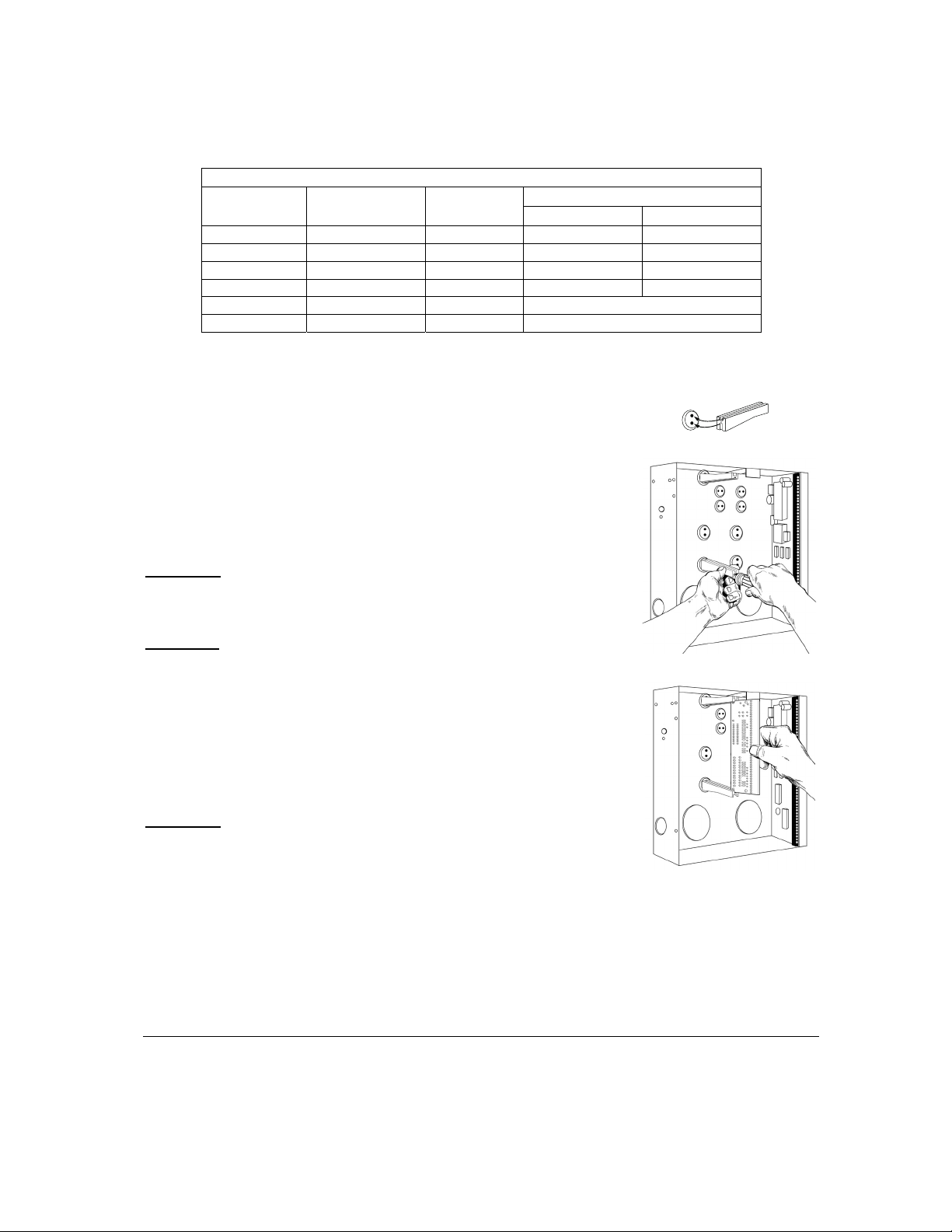
ENCLOSURE DIAGRAM
Inside the can, several 2-holed insertion points have been
constructed. This allows for either vertical or horizontal placement of
the modules. Notice that the insertion points have two sizes of
holes -- a larger hole and a smaller hole.
Diagram 1
: The black plastic PCB guides are grooved on one edge
where the PC Board will be seated. The end with the half-moon
protrusion fits into the larger hole. The smaller hole is for the screw.
Diagram 2
: Place the first black plastic PCB guide in the top insertion
point, grooved edge downward. The half-moon protrusion will be in
the large hole. It does not require force. Insert one of the provided
screws into the smaller hole (from inside the can) to secure it in place.
A screwdriver should reach through the notch that runs the length of
the guide to tighten the screw. The second PCB guide should be
positioned opposite of the first (grooved edge up) and placed in the
lower insertion point, using the same procedures described above.
Once mounted, screw it in securely.
Diagram 3
: The PC board should slide freely in the grooves of both
guides.
NX-584 Home Automation
3
Page 4
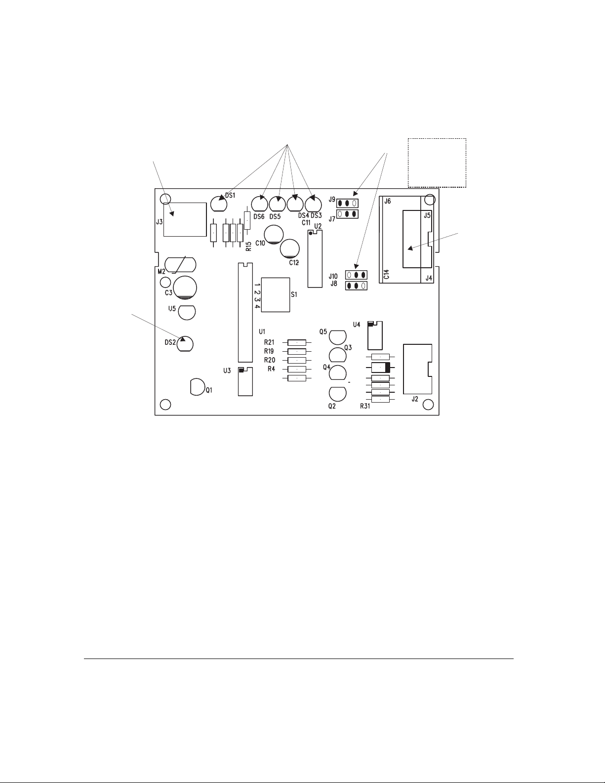
IV. WIRING DIAGRAM
LED
for circuit
operation
only
CONNECT TO
NX-8 TERMINALS
DATA
COM
POS
LEDS
“B”
“B”
Jumpers
“A”
“A”
“A” Pos / “B” Pos
J9 =8 /7*
J7 =8*/7
J10=2*/3
J8 =2 /3*
* Default Position
ATTACH THE HOST
TO THIS CONNECTOR
V.
ENROLLING THE MODULE
The NetworX control panels have the ability to automatically find and store in memory the presence
of all keypads, zone expanders, wireless receivers, output modules, and any other device on the
keypad buss. This allows these devices to be supervised by the control panel. To enroll the devices,
enter the Program Mode using the procedure outlined in the control panel Installation Manual. When
the Program Mode is exited, the NX-8 control will automatically enroll the devices. The enrolling
process takes about 12 seconds, during which time the AService@ LED will illuminate. User codes will
not be accepted during the enrolling process. Once a module is enrolled, if it is not detected by the
control, the AService@ LED will illuminate.
4
NX-584 Home Automation
Page 5

VI. PROGRAMMING THE MODULE
A. USING THE LED KEYPAD
To enter the Program Mode:
Enter [r]-[8] (all of the function key LEDs will begin to flash).
Enter the "Go To Program" code (default is [9]-[7]-[1]-[3]). If the code was valid, the
Service LED will flash, and the function LEDs will illuminate steady, indicating the device
to program should be entered.
Enter the address of the NX-584, which is [7] [2] followed by [#]. At this point, the Armed LED
will illuminate while it is waiting for a programming location to be entered.
Enter the desired programming location followed by the [#] key.
The Armed LED will begin to flash while a programming location is being entered. If this
is a valid location, the Armed LED will extinguish, the Ready LED will illuminate, and the
binary data for the first segment of this location will be shown on the zone LEDS.
If the desired location is the next sequential location, press the [POLICE] key.
If the previous location is desired press the [FIRE] key.
If the same location is desired press the [AUXILIARY] key.
To change the data, enter the data followed by [r].
The data will be entered, and the location will automatically increment to the next
segment. The data for that segment will be displayed. This procedure is repeated until
the last segment is reached.
To exit this location without changing the data, press the [#] key.
To review the data, repeat the above procedure, pressing the [ r] key without entering data first.
Each time the [r] key is pressed, the next segment is displayed. After the last segment of a
location is programmed, pressing the [r] key will exit that location, turn the "Ready" LED off and
the "Armed" LED on. As before, you are now ready to enter another programming location. If an
attempt is made to program an invalid entry for a particular segment, the keypad sounder will
emit a triple error beep (beep, beep, beep) and remain in that segment awaiting a valid entry.
To exit the Program Mode, press the [Exit] key to exit this programming level. Pressing the
[Exit] key again will exit the Program Mode.
B. U
SING THE LCD KEYPAD
All steps required for programming are the same as the aforementioned LED keypad. The LCD
keypad display will prompt you for the data required. While in the programming mode, and not in a
location, the number in parenthesis is the location you were previously changing. For example, if the
display reads "Enter location, then # (2)", it is reminding you that location 2 was the last location you
programmed. In feature selection data, the numbers of the enabled features will be displayed. The
features not enabled will display a hyphen (-).
VII. PROGRAMMING DATA
Programming data is always one of two types. One type of data is numerical, which can values from
0 -15 or 0-255 depending on the segment size. The other type of data, feature sel ection data , is used
to turn features on or off. Use the following procedures with these two data types:
NX-584 Home Automation
5
Page 6

Numerical Data: Numerical data is programmed by using the numeric keys of the system keypad to
LED INDICATIONS
DS1
DS3
DS4
DS5
DS6
enter a number from 0-255. To view the data in a location, a binary process is used. With this
process, the LED’s for zones 1 through 8 are utilized, and the numeric equivalents of their illuminated
LED’s are added together to determine the data in a programming location. The numeric equivalents
of these LED’s are as follows:
Zone 1 LED = 1 Zone 3 LED = 4 Zone 5 LED = 16 Zone 7 LED = 64
Zone 2 LED = 2 Zone 4 LED = 8 Zone 6 LED = 32 Zone 8 LED = 128
Example: If the numerical data to be programmed in a location is "66", press [6]-[6] on the keypad.
The LED’s for Zone 2 and Zone 7 will become illuminated indicating 66 is in that location (2 + 64 =
66). Once the data is programmed, press the [r] key to enter the data and advance to the next
segment of that location. After the last segment of a location is programmed, pressing the [r] key will
exit that location, turn the "Ready" LED off and the "Armed" LED on. As before, you are now ready to
enter another programming location. If an attempt is made to program a number too large for a
particular segment, the keypad sounder will emit a triple beep, indicating an error, and remain in that
segment awaiting a valid entry.
Feature Selection Data: Feature selection data will display the current condition (on or off) of eight
features associated with the programming location and segment selected. Pressing a button on the
touchpad (1 through 8) that corresponds to the "feature number" within a segment will toggle (on/off)
that feature. Pressing any numeric key between [1] and [8] for selection of a feature will make the
corresponding LED illuminate (feature ON). Press the number again, and the LED will extinguish
(feature OFF). You will see that numerous features can be selected from within one segment. For
instance, if all eight features of a segment are desired, pressing [1]-[2]-[3]-[4]-[5]-[6]-[7]-[8] will turn on
LED's 1 through 8 as you press the keys, indicating that those features are enabled.
LCD KEYPAD USERS NOTE:
The numbers of the enabled features will be displayed. However, the features not enabled will
display a hyphen (-). After the desired setting of features is selected for this s egment, pres s the [r]
key. This will enter the data and automatically advance to the next segment of the location. When you
are in the last segment of a location and press the [r] to enter the data, you will exit that location.
This will now turn the "Ready" LED off and the "Armed" LED on. As before, you are now ready to
enter another programming location.
VIII.
LEDS INDICATORS
Flashes for NetworX buss
Flashes for each valid packet received from host
Flashes for each packet transmitted to host
On when waiting for NetworX function to be completed
On when waiting for acknowledgement from host
6
NX-584 Home Automation
Page 7

IX. PROGRAMMING LOCATIONS
LOCATION 0 PROGRAMMING THE OPTION FLAGS
(1 segment of feature selection data) The NX-584 protocol can operate in one of two possible modes
- binary or ASCII. Consult the home automation application information to determine the proper mode
for your application and program it in Location 0.
Option 1 LED 0ff = Binary LED On = ASCII
Options 2 - 8
Reserved
LOCATION 1 BAUD RATE TABLE
(1 segment of numerical data) The NX-584 can operate on a number of different baud rates. Consult
the home automation application information to determine the best baud rate for your application and
program it in Location 1.
DATA BAUD RATE DATA BAUD RATE
0 600 Baud 4 9600 Baud (9.6K)
1 1200 Baud (1.2K) 5 19200 Baud (19.2K)
2 2400 Baud (2.4K) 6 38400 Baud (38.4K)
3 4800 Baud (4.8K) 7 76800 Baud (76.8K)
LOCATION 2 ENABLING THE TRANSITIONS
(2 segments of feature selection data) The NX-584 can be programmed to automatically send
information to the home automation system whenever there has been a change in this information.
This is referred to as ‘transition-based broadcasting’. Which information packets use ‘transition-b ased
broadcasting’ is dependent upon the application and the capabilities of the home automation system.
Location 2 is used to enable and disable the appropriate transition based broadcasts. Consult the
home automation application information and enable the appropriate transition-based broadcasts in
Location 2.
Segment 1:
DATA ENABLES TRANSITION
1
2
3-4
5
6
7
8
NX-584 Home Automation
Reserved
Interface Configuration at power-up / end of download / program mode
Reserved
Zone Status Message
Zones Snapshot Message
Partition Status Message
Partitions Snapshot Message
7
Page 8

Segment 2:
DATA ENABLES TRANSITION
1
2
3
4
5 - 8
System Status Message
X-10 Message Received
Log Event Message
Keypad Message Received
Reserved
LOCATION 3 PROGRAMMING THE COMMAND / REQUEST ENABLES
(4 segments of feature selection data) The NX-584 has the ability to perform a variety of commands
asked of it by the home automation system. For example, it is possible to allow arming and disarming
of the security system, programming of the security system, or bypassing of zones by the home
automation system. Location 3 is used to select which commands, if any, you wish the home
automation system to have access. Consult the home automation application information and enable
the appropriate commands for your application. CAUTION: IT IS IMPORTANT TO UNDERSTAND
THE CAPABILITES OF THE HOME AUTOMATION SYSTEM TO AVOID COMPROMISING THE
SECURITY OF YOUR SYSTEM WHEN PROGRAMMING THIS LOCATION.
DATA SUPPORTED REQUEST / COMMAND
1
2
3
4
5
6
7
8
Segment 2:
Reserved
Interface Configuration Request
Reserved
Zone Name Request
Zone Status Request
Zones Snapshot Request
Partition Status Request
Partitions Snapshot Request
DATA SUPPORTED REQUEST / COMMAND
1
2
3
4
5
6 - 8
8
NX-584 Home Automation
System Status Request
Send X-10 Message
Log Event Request
Send Keypad Text Message
Keypad Terminal Mode Request
Reserved
Page 9

Segment 3:
KEYPAD
PART 1
PART 2
PART 3
PART 4
PART 5
PART
6 PART 7
PART 8
DATA SUPPORTED REQUEST / COMMAND
1
2
3
4
5
6
7
8
Program Data Request
Program Data Command
User Information Request with PIN
User Information Request without PIN
Set User Code Command with PIN
Set User Code Command without PIN
Set User Authorization Command with PIN
Set User Authorization Command without PIN
Segment 4:
DATA SUPPORTED REQUEST / COMMAND
1
2
3
4
5
6
7
8
Reserved
Reserved
Store Communication Event Command
Set Clock / Calendar Command
Primary Keypad Function with PIN
Primary Keypad Function without PIN
Secondary Keypad Function
Zone Bypass Toggle
LOCATION 4 PROGRAMMING THE LCD KEYPAD ADDRESS
(1 segment) Certain commands in the NX-584 require it to know the location of at least 1 LCD
keypad (if one exists in the system). If your system has an LCD keypad it is recommended that it
be placed in partition 1 keypad 1. This will allow location 4 to be left at the factory default. If the
LCD keypad is selected as something other than partition 1/keypad 1, program the appropriate
address in location 4. Select the address from the following chart.
1 192 193 194 195 196 197 198 199
2 200 201 202 203 204 205 206 207
3 208 209 210 211 212 213 214 215
4 216 217 218 219 220 221 222 223
5 224 225 226 227 228 229 230 231
6 232 233 234 235 236 237 238 239
7 240 241 242 243 244 245 246 247
8 248 249 250 251 252 253 254 255
NX-584 Home Automation
9
Page 10

X. PROGRAMMING WORKSHEETS
(Defaults are printed in bold italics text in a shaded area.)
LOC PG DESCRIPTION
0 7
Option Flags (1 segment)
Option 1
Off = Binary “
On = ASCII “
Options 2 - 8 Reserved
1 7
2 7
Baud Rate (1 segment)
0 = 600 Baud
“
1 = 1200 (1.2K)
“
2 = 2400 (2.4K)
“
3 = 4800 (4.8K)
“
“ 4 = 9600 (9.6K)
5 = 19200 (19.2K)
“
6 = 38400 (38.4K)
“
7 = 76800 (76.8K)
“
Enabling the Transitions (2 segments)
1 = Reserved
“ 2 = Interface Configuration
3 –4 = Reserved
Segment 1
5 = Zone Status Message
“
6 = Zones Snapshot Message
“
“ 7 = Partition Status Message
8 = Partitions Snapshot Message
“
“ 1 = System Status Message
“ 2 = X-10 Message Received
Segment 2
3 = Log Event Message
“
4 = Keypad Message Received
“
5 – 8 = Reserved
3 8 Programming the Command / Request Enables (4 segments)
1 = Reserved
“ 2 = Interface Configuration Request
3 = Reserved
Segment 1
“ 4 = Zone Name Request
“ 5 = Zone Status Request
“ 6 = Zones Snapshot Request
“ 7 = Partition Status Request
“ 8 = Partitions Snapshot Request
“ 1 = System Status Request
“ 2 = Send X-10 Message
Segment 2
“ 3 = Log Event Request
“ 4 = Send Keypad Text Message
“ 5 = Keypad Terminal Mode Request
6 – 8 = Reserved
10
NX-584 Home Automation
Page 11

LOC PG DESCRIPTION
1
192
193 194 195 196 197 198 199
3 8
Segment 3
1 = Program Data Request
“
2 = Program Data Command
“
3 = User Information Request with PIN
“
4 = User Information Request without PIN
“
5 = Set User Code Command with PIN
“
6 = Set User Code Command without PIN
“
7 = Set User Authorization Command with PIN
“
8 = Set User Authorization Command without
“
PIN
1 – 2 = Reserved
3 = Store Communication Event Command
“
Segment 4
“ 4 = Set Clock / Calendar Command
5 = Primary Keypad Function with PIN
“
6 = Primary Keypad Function without PIN
“
“ 7 = Secondary Keypad Function
8 = Zone Bypasss Toggle
“
4 9 LCD Keypad Address (1 segment)
2 200 201 202 203 204 205 206 207
3 208 209 210 211 212 213 214 215
4 216 217 218 219 220 221 222 223
5 224 225 226 227 228 229 230 231
6 232 233 234 235 236 237 238 239
7 240 241 242 243 244 245 246 247
8 248 249 250 251 252 253 254 255
NX-584 Home Automation
11
Page 12

XI.
SPECIFICATIONS
NX-584 DIMENSIONS 4 " Width x 3.25 " Length x 1 " Depth
OPERATING POWER 12 VDC, Supplied from NX-8 or NX-320
AUXILIARY POWER Supplied by NX-8 or NX-320
NX-584 CURRENT DRAW 30 mA
OPERATING TEMPERATURE 32 to 120 degrees F
SHIPPING WEIGHT 1 lb.
NX-584 INSTALLATION MANUAL
NX584IB03 REV B (01-10-03)
 Loading...