

Page 1

NX-582E
AES RADIO INTERFACE
TABLE OF CONTENTS
GENERAL DESCRIPTION........................................................... 2
ENCLOSURE INFORMATION ...................................................... 2
ADDRESSING ......................................................................... 3
ENROLLING............................................................................ 3
UNDERSTANDING THE LIGHTS .................................................3
WIRING THE INTERFACE..........................................................4
NX-582 LAYOUT...................................................................... 4
TERMINAL DESCRIPTION .........................................................4
WIRE REQUIREMENTS .............................................................5
PROGRAMMING THE INTERFACE ...............................................5
PROGRAMMING DATA..............................................................6
PROGRAMMING THE LOCATIONS............................................... 8
PROGRAMMING WORKSHEETS..................................................9
SPECIFICATIONS .................................................................. 12
Page 2
GENERAL DESCRIPTION
The NX582-E is a microprocessor-controlled AES radio interface. This interface
allows any or all events from the NX8/NX8E control panel to be reported via the
AES radio Models 7050-E, 7050-DLR (v2.2 or higher), 7450, 7450-XL, 7750, and
7750-F.
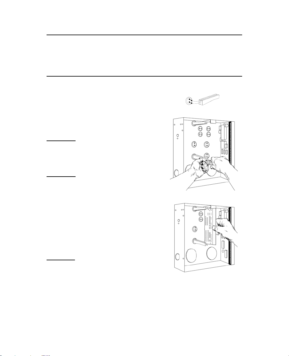
ENCLOSURE INFORMATION
Inside the can, several 2-holed insertion points
have been constructed. This allows for either
vertical or horizontal placement of the modules.
Notice that the insertion points have two
sizes of holes -- a larger hole and a smaller
hole.
Diagram 1
grooved on one edge where the PC Board will be
seated. The end with the half-moon protrusion
fits into the larger hole. The smaller hole is for
the screw.
Diagram 2
guide in the top insertion point, grooved edge
downward. The half-moon protrusion will be in
the large hole. It does not require force. Insert
one of the provided screws into the smaller hole
(from inside the can) to secure it in place. A
screwdriver should reach through the notch that
runs the length of the guide to tighten the
screw. The second PCB guide should be
positioned opposite of the first (grooved edge
up) and placed in the lower insertion point,
using the same procedures described above.
Once mounted, screw it in securely.
Diagram 3
the grooves of both guides.
: The black plastic PCB guides are
: Place the first black plastic PCB
: The PC board should slide freely in
2
Page 3
ADDRESSING
The NX582-E has a fixed address of 77. When programming the interface, enter
the Program Mode and select the device address as [7]-[7]. (See "Programming
the NX582-E", page 5.)
ENROLLING
The NX8/NX8E has the ability to automatically find and store in its memory the
presence of all keypads, zone expanders, wireless receivers, and any other
device on the keypad buss. This allows these devices to be supervised by the
control panel and illuminate the "Service" LED if one is not detected. To enroll
the devices, enter the Program Mode of the NX8/NX8E control panel using the
procedure outlined in the Installation Manual. When the Program Mode is exited,
the NX8/NX8E will automatically enroll the devices. The enrolling process takes
about 12 seconds, during which time the AService@ LED will illuminate. User
codes will not be accepted during the enrolling process. Once a module is
enrolled, if it is not detected by the control, the AService@ LED will illuminate.
UNDERSTANDING THE LIGHTS
The NX582-E has five (5) red LEDs along the front of the board. These LEDs
provide valuable information about the status of the NX582-E and the AES radio
as follows:
LED
DS1
DS3
DS4
DS5
DS6
NOTE: DS3 through DS6 will be off if the system is initialized, normal and
waiting for a new event to report.
DS2
Flashes each time the NX582-E has an opportunity to speak to the
control panel. It should be flashing about two times each second.
Flashes when it is attempting to establish communication with the
AES radio.
Flashes when the AES radio acknowledges receipt of the event
message.
Flashes when the NX582-E sends a test APing@ to the AES radio.
Flashes when the AES radio responds with a good reply to the test
APing@.
The sixth LED is located toward the back of the board. It is used for
hardware, and will only glow dimly when connected to the NX8/NX8E
control.
DESCRIPTION
3
Page 4
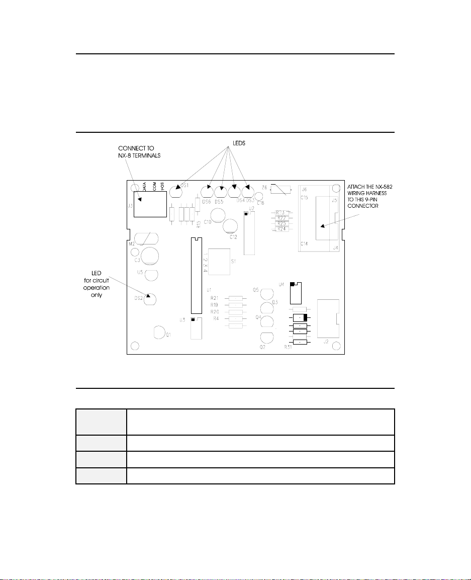
WIRING THE INTERFACE
Wire the 3-position terminal on the NX582-E to the NX8/NX8E control panel
keypad interface as follows: Positive to KP POS, COM to KP COM, and DATA to
KP DATA. Connect the wiring harness from the NX582-E connector labeled J6 to
the AES radio connector labeled J1. Refer to connection diagram.
NX-582E LAYOUT
TERMINAL DESCRIPTION
Table 1.1
POS
COM
DATA
J6
Connect to the KP POS terminal of the NX8/NX8E. Current draw is
30 mA for the NX582-E.
Connect to the KP COM terminal of the NX8/NX8E.
Connect to the KP DATA terminal of the NX8/NX8E.
Connect to the cable of the AES radio.
4
Page 5
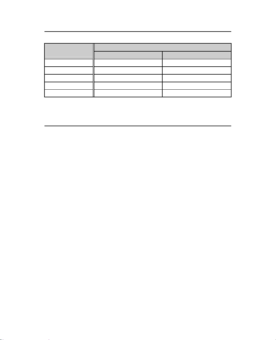
WIRE REQUIREMENTS
Table 2.1
(Feet)
250 24 24
500 24 22
1000 22 20
2000 20 16
2500 18 16
PROGRAMMING THE NX582-E
USING THE LED KEYPAD
• Entering the Program Mode
To enter the Program Mode, press [r]-[8]. At this time, the five function
LEDs (Stay, Chime, Exit, Bypass, & Cancel) will begin to flash. Next, enter
the "Go To Program Code" (Factory Default is [9]-[7]-[1]-[3]). If the "Go To
Program Code" is valid, the "Service" LED will flash and the five function
LEDs will illuminate steady. You are now in the Program Mode and ready to
select the module to program.
# Select the Module to Program
All modules connected to the NX8/NX8E are programmed through the
keypad. Enter the address of the NX582-E, which is [7]-[7], followed by [#].
The Armed LED will illuminate while it is waiting for a programming location
to be entered. Other module entry numbers can be found in their
corresponding manuals.
# Programming a Location
Once the number of the module to be programmed has been entered, the
"Armed" LED will illuminate, indicating it is waiting for a programming
location to be entered. Any location can be accessed by directly entering the
desired programming location followed by the pound [#] key. If the location
entered is a valid location, the "Armed" LED will extinguish, the "Ready" LED
will illuminate and the binary data for the first segment of this location will be
shown by the zone LED's. While entering new data, the "Ready" LED will
begin flashing to indicate a data change in process. The flashing will
continue until the new data is stored by pressing the [r] key. Upon pressing
the [r] key, the keypad will advance to the next segment and display its
Connected to NX8/NX8E Connected to NX-320
Wire Gauge Length
5
Page 6

data. This procedure is repeated until the last segment is reached. Pressing
the [#] key will exit from this location, and the "Armed" LED will illuminate
again waiting for a new programming location to be entered. If the desired
location is the next sequential location, press the [POLICE] key. If the
previous location is desired press the [FIRE] key. If the same location is
desired press the [MEDIC] key. To review the data in a location, repeat the
above procedure, pressing the [r] key without any numeric data entry. Each
time the [r] key is pressed, the programming data of the next segment will
be displayed for review.
# Exiting a Location
After the last segment of a location is programmed, pressing the [r] key will
save the data, exit that location, turn the "Ready" LED off and the "Armed"
LED on. The [r] key must be pressed or the data will not be changed. Press
the [#] key to exit a location before the last segment without saving the
changes. As before, you are now ready to enter another programming
location. If an attempt is made to program an invalid entry for a particular
segment, the keypad sounder will emit a triple error beep (beep, beep,
beep), and remain in that segment awaiting a valid entry.
# Exiting the Program Mode:
When all the desired changes in programming have been made, it is time to
exit the program mode. Pressing the [Exit] key will exit this programming
level, and go to the "Select a Module To Program" level. If no additional
modules are to be programmed, pressing the [Exit] key again will exit the
program mode. If there is a module to be programmed, it may be selected
by entering its address followed by the [#] key. The procedure for
programming these devices is the same, except the locations will be for the
module selected.
USING THE LCD KEYPAD
# All steps required for programming are the same as the aforementioned LED
keypad. The LCD keypad display will prompt you for the data required.
While in the programming mode, and not in a location, the number in
parenthesis is the location you were previously changing. For example, if the
display reads "Enter location, then # (5)", it is reminding you that location
5 was the last location you programmed. Refer also to "Programming Data"
which follows.
PROGRAMMING DATA
Programming data is always one of two types. One type of data is numerical,
which can take on values from 0 -15 or 0 -255 depending on the segment size.
The other type of data, feature selection data, is used to turn features on or off.
Use the following procedures with these two data types:
6
Page 7

1. Numerical Data
Numerical data is programmed by entering a number from 0-255 on the
numeric keys of the system keypad. To view the data in a location, a binary
process is used. With this process, the LED=s for zones 1 through 8 are
utilized, and the numeric equivalents of their illuminated LED=s are added
together to determine the data in a programming location. The numeric
equivalents of these LED=s are as follows:
2. Feature Selection Data
Zone 1 LED = 1
Zone 2 LED = 2
Zone 3 LED = 4
Zone 4 LED = 8
Example: If the numerical data to be programmed in a location is "66", press
[6]-[6] on the keypad. The LED=s for Zone 2 and Zone 7 will become
illuminated indicating 66 is in that location (2 + 64 = 66). Once the data is
programmed, press the [r] key to enter the data and advance to the next
segment of that location. After the last segment of a location is
programmed, pressing the [r] key will exit that location, turn the "Ready"
LED off and the "Armed" LED on. As before, you are now ready to enter
another programming location. If an attempt is made to program a number
too large for a particular segment, the keypad sounder will emit a triple
beep, indicating an error, and remain in that segment awaiting a valid entry.
Feature selection data will display the current condition (on or off) of eight
features associated with the programming location and segment selected.
Pressing a button on the touchpad (1 - 8) that corresponds to the "feature
number" within a segment will toggle (on/off) that feature. Pressing any
numeric key between [1] and [8] for selection of a feature will make the
corresponding LED illuminate (feature ON). Press the number again, and the
LED will extinguish (feature OFF). You will see that numerous features can
be selected from within one segment. For instance, if all eight features of a
segment are desired, pressing [1]-[2]-[3]-[4]-[5]-[6]-[7]-[8] will turn on
LED's 1 thru 8 as you press the keys, indicating that those features are
enabled. LCD Keypad Users Note
will be displayed. However, the features not enabled will display a (-)
hyphen. After the desired setting of features is selected for this segment,
press the [r] key. This will enter the data and automatically advance to the
next segment of the location. When you are in the last segment of a location
and press the [r] to enter the data, you will exit that location. This will now
turn the "Ready" LED off and the "Armed" LED on. As before, you are now
ready to enter another programming location.
Zone 5 LED = 16
Zone 6 LED = 32
Zone 7 LED = 64
Zone 8 LED = 128
: The numbers of the enabled features
7
Page 8

PROGRAMMING THE LOCATIONS
Location 0 - Account Code (6 segments numerical data)
This account number is provided by AES. Enter the account code followed by a
“10" in the segment immediately after the last digit. If the account code is 6
digits long, program all 6 digits.
Location 1 - Partitions To Be Reported (1 segment feature selection data)
This location contains the partition(s) that sho ul d b e i nc luded wh en re po rt in g v ia
the AES radio. If you wish to exclude any partition from reporting, simply turn off
the LED corresponding to that particular partition. NOTE: If the partition LED
is off, NO event from that partition will report, regardless of what is
programmed in locations 3 through 6.
LED Partition LED Partition
1 1 5 5
2 2 6 6
3 3 7 7
4 4 8 8
Location 2 - Transmission Format (1 segment numerical data)
Location 2 contains the transmission format to be used.
Number Format
0 Contact ID
1 SIA
2 4+2
Locations 3 & 4 - Events That Can be Enabled When Phone Fault Is
Detected (8 segments feature selection data)
Locations 3 and 4 are used to select certain events to be sent via the AES radio
when a phone fault condition is detected. Turn the LED on for the corresponding
events to be reported. These events will only
faulted. Refer to the programming worksheets on pages 9-13 for events.
Locations 5 & 6 - Events That Can Be Enabled When Phone Line Is Good
(8 segments of feature selection data)
Locations 5 and 6 are used to select certain events to be sent via the AES radio.
Turn the LED on for the corresponding events to be reported. These reports will
only be sent when the phone line is good. Note: If you want the reports sent
regardless of the phone line condition (good or faulted), you must
program locations 3 through 6.
be sent if the phone line is bad or
8
Page 9
PROGRAMMING WORKSHEETS
LOC DESCRIPTION
0 Account Code (from provider) Default: AAAAAA
Partition Event Enables 1
1 - Partition 1
2 - Partition 2
3 - Partition 3
4 - Partition 4
Transmission Format 2
0 - Contact ID ‘
1 - SIA ‘
2 - 4+2 ‘
Events That Can Be Enabled During Phone Fault (8 segments)
3
Segment 1
1 - Alarm ‘
2 - Restore ‘
3 - Shunt ‘
4 - Shunt Restore ‘
Segment 2
1 - Sensor Low Battery ‘
2 - Sensor Low Batt Restore
3 - Sensor Missing
4 - Sensor Missing Restore
5 – 8 Reserved
Segment 3
1 - Reserved
2 - Reserved
3 - Duress
4 - Auxiliary 1
Segment 4
1 - Box Tamper ‘
2 - Box Tamper Restore
3 - AC Fail
4 - AC Restore
Segment 5
1 - Siren Tamper
2 - Siren Tamper Restore
3 - Phone Line Monitor
4 - Phone Monitor Restore
‘
‘
‘
‘
‘
‘
‘
‘
‘
‘
‘
5 – Partition 5
6 – Partition 6
7 – Partition 7
8 – Partition 8
5 - Tamper
6 - Tamper Restore
7 - Trouble
8 - Trouble Restore
‘
‘
5 – Auxiliary 2
6 - Holdup (Silent Panic)
7 - Keypad Panic
8 - Keypad Tamper
5 - Low Battery (system)
6 - Low Battery Restore
‘
7 - Fuse (over current)
8 - Fuse (over current)
Restore
5 - Expander Trouble
6 - Exp. Trouble Restore
‘
7 - Fail to Communicate
8 - Log Full ‘
‘
‘
‘
‘
‘
‘
‘
‘
‘
‘
‘
‘
‘
‘
‘
‘
‘
‘
‘
‘
9
Page 10

Segment 6
1 - Open ‘
2 - Close ‘
3 - Exit Error ‘
4 - Recent Close ‘
Segment 7
1- Download Complete ‘
2- Cancel
3- Ground Fault
Segment 8 Reserved
Events That Can Be Enabled During Phone Fault
4
(8 segments)
Segments 1 - 7 Reserved
Segment 8
1 – 7 Reserved
8 - Fail to Communicate / Data Lost ‘
Events That Can Be Enabled During Phone Normal
5
(8 segments)
Segment 1
1 - Alarm ‘
2 - Restore ‘
3 - Shunt ‘
4 - Shunt Restore ‘
Segment 2
1 - Sensor Low Battery ‘
2 - Sensor Low Battery
Restore
Segment 3
1 – 2 Reserved
3 - Duress
4 - Auxiliary 1
5 - Auxiliary 2
Segment 4
1 - Box Tamper ‘
2 - Box Tamper Restore
3 - AC Fail
4 - AC Restore
Segment 5
1 - Siren Tamper
2 - Siren Tamper Restore
3 - Phone Line Monitor
4 - Phone Monitor Restore
‘
‘
‘
‘
‘
‘
‘
‘
‘
‘
5 - Autotest
6 - Program Start ‘
7 - Program End ‘
8 - Download Start
4- Ground Fault Restore
5- Maintenance Test
6- 8 Reserved
5 - Tamper
6 - Tamper Restore
7 - Trouble
8 - Trouble Restore
3 - Sensor Missing
4 - Sensor Missing Restore
5 – 8 Reserved
6 - Holdup (Silent Panic)
7 - Keypad Panic
8 - Keypad Tamper
5 - Low Battery (system)
6 - Low Battery Restore
‘
7 - Fuse (overcurrent)
8 – Fuse Restore
5 - Expander Trouble
6 - Exp. Trouble Restore
‘
7 - Fail to Communicate
8 - Log Full ‘
‘
‘
‘
‘
‘
‘
‘
‘
‘
‘
‘
‘
‘
‘
‘
‘
‘
‘
‘
‘
‘
10
Page 11

Segment 6
1 - Open ‘
2 - Close ‘
3 - Exit Error ‘
4 - Recent Close ‘
Segment 7
1 - Download Complete ‘
2 - Cancel
3 - Ground Fault
Segment 8 Reserved
Events That Can Be Enabled During Phone Normal
6
(8 segments)
Segment 1 - 7 Reserved
Segment 8
1 – 7 Reserved
8 - Fail to Communicate - Data Lost
‘
‘
SYSTEM NOTES
5 - Autotest
6 - Program Start ‘
7 - Program End ‘
8 - Download Start
4 - Ground Fault Restore
5 - Maintenance Test
6 – 8 Reserved
‘
‘
‘
‘
‘
11
Page 12

OPERATING POWER 12VDC Supplied from NX8 or
NX8E or NX-320
AUXILIARY POWER Supplied from NX8/NX8E
CURRENT DRAW 30 mA
OPERATING TEMPERATURE 32 to 120 degrees F
DIMENSIONS 4.0" Wide
SHIPPING WEIGHT 1 lbs.
SPECIFICATIONS
or NX-320
3.25" High
1.0" Deep
1420 N. Main Street
Gladewater, Texas 75647
Main 800-727-2339 Technical Support 800-727-2339
Outside the US 903-845-6941 Tech Support Fax 903-845-8409
Main Fax 903-845-6811 Sales & Literature 800-547-2556
Web: www.caddx.com
www.ge-interlogix.com
NX-582E INSTALLATION MANUAL
NX582EIA03 REV. A (05-30-03)
 Loading...