


A
NetworX NX-548E Receiver Installation
Instructions
Content
Introduction ..................................................................... 1
Internal mounting ............................................................ 1
External mounting........................................................... 2
Wiring ........................................................................... 3
DIP switch settings ......................................................... 3
Power up......................................................................... 3
Programming .................................................................. 4
Testing and troubleshooting ........................................... 7
Programming settings table............................................ 7
Supported devices........................................................ 11
Specifications................................................................ 12
Regulatory information ................................................. 12
Contact information....................................................... 12
Introduction
The NX-548E Receiver adds wireless capabilities to the
NetworX line of control panels. Adding a receiver makes these
control panels compatible with NX wireless transmitters.
Only three wire connections are required for power and
communication to the control panel.
Internal mounting
3. Insert the shrouds into the knockout holes (Figure 1
Figure 1. Installing the antenna shrouds
ntenna shroud
Enclosure top
O-ring
Knockout hole
4. Use the mounting screw provided to loosely install the
edge guide standoff in the lower mounting hole in the
appropriate space to the left of the control panel (Figure
2). Do not tighten the mounting screw down at this time.
Figure 2. Installing the edge guide standoffs
).
For internal mounting, mount the receiver inside the control
panel enclosure. Use the following installation guidelines:
• Leave at least 10 in. (25 cm) above the control panel for
the receiver’s antennas.
• Avoid areas that expose the receiver to moisture.
• Avoid areas with excessive metal or electrical wiring,
including furnaces and utility rooms.
To mount the receiver, do the following:
1. Remove the appropriate knockouts on the top of the
control panel enclosure for the antenna shrouds.
2. Assemble the antenna shrouds and fit the black O-rings to
the bottom of each shroud.
P/N 466-2225 • REV C • January 2011 1
Caution: You must be free of static electricity before handling
circuit boards. Touch a bare metal surface or wear a grounding
strap to discharge yourself.
5 Slide the printed circuit board into the antennae shroud
slots, after inserting wires into antennae shrouds (Figure
3).
Mounting screw
Edge guide standoff
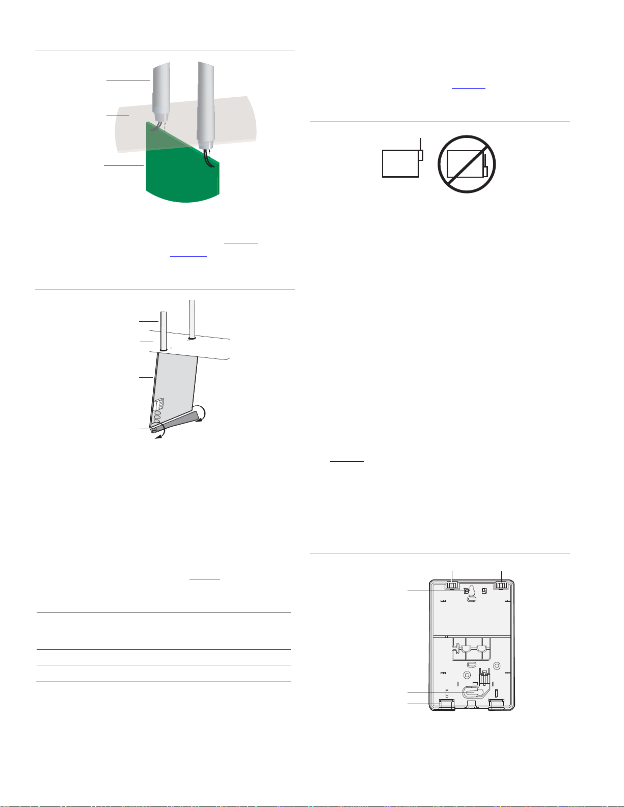
Figure 3. A
ntenna shrouds
Antennae
shrouds
• Avoid areas with excessive metal or electrical wiring
including furnace and utility rooms. If unavoidable, mount
on or near metal with the antenna extending above the
metallic surfaces as shown in Figure 5
.
Enclosure
Circuit
board
6. Align the bottom of the circuit board in the edge guide
standoff and twist the standoff into place (Figure 4
Tighten the mounting screw (Figure 2
Figure 4. Installing the circuit board
Antenna shroud
Enclosure
Circuit board
).
).
Figure 5. Mounting on or near metal
METAL
METAL
Tools and supplies needed
To complete the installation, you will need the following tools
and supplies:
• Screwdrivers;
• Drill with bits;
• Mounting screws and anchors (included); and
• 3-conductor, 22-gauge (0.65 mm) or larger, stranded wire.
Mounting
The module can be mounted on any interior wall (protected
from the elements). To mount the module, do the following:
Edge guide standoff
External mounting
This installation uses enclosure model NX-569 (600-1029-03).
The module comes as a kit that is assembled in the field. Use
the following installation guidelines:
• Allow at least 10 in. (25 cm) of clearance above the
enclosure for the antennas.
• Use the wire length guidelines in Table 1
Table 1. Wire lengths
Wire gauge
(shielded or
unshielded)
22 AWG (0.65 mm) 250 feet (76 m)
18 AWG (1.02 mm) 500 feet (152 m)
Maximum wire length between module
and panel
• Install the module in its own plastic enclosure. It should
not be installed inside the panel’s enclosure.
.
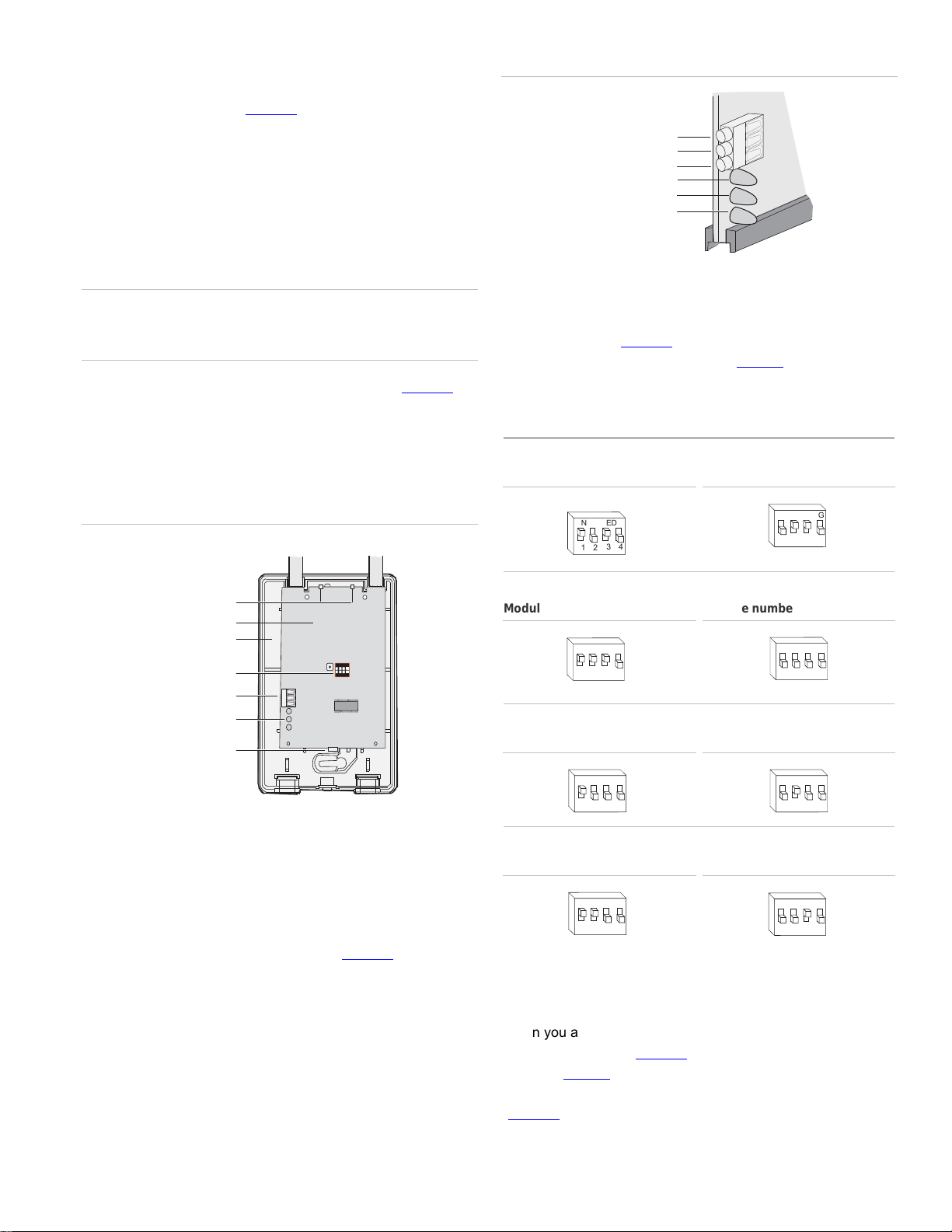
1. Remove the module back plate from the packaging.
2. Hold the base against the mounting surface and mark the
two mounting holes and the wire access hole as shown in
Figure 6
. Remember to leave at least 10 in. (25 cm) above
the back plate for the antennas.
Note: The wire access hole is molded into the plastic so
that you can access the wire, yet keep it hidden from the
back plate.
Figure 6. Back plate
Antenna shroud locations
Mounting hole
Mounting hole
Wire access
• Avoid mounting locations that expose the module to
moisture.
2 NetworX NX-548-E Receiver Installation Instructions
3. Drill holes and insert the appropriate anchors (included).
4 Run a 3-conductor, 22 or 18 gauge (0.65 or 1.02 mm)
ON EC
E
1 2 3 4
stranded wire cable from the module wire access hole
location to the panel (Figure 6
).
Figure 8. Receiver wiring connections and LEDs
5. Secure the back plate to the wall with the pan head
screws provided.
6. To assemble the antenna shrouds, attach the proper
number of sections together, then attach the top cap.
7. Install each antenna shroud on top of the back plate.
8. Remove the transceiver circuit board from the antistatic bag
Caution: You must be free of static electricity before handling
circuit boards. Touch a bare metal surface or wear a grounding
strap to discharge yourself.
9. To install the circuit board onto the back plate (Figure 7),
insert the antennas into the antenna shrouds, then gently
slide the top of the circuit board under the two top latches,
and snap the circuit board in at the bottom latch to secure
it in place.
Figure 7. Circuit board and back plate
Antenna shrouds
+ 12 (to panel POS)
GND (to panel COM)
DATA (to panel DATA)
Green (power) LED
Red (data) LED
Red (not used) LED
DIP switch settings
The DIP switches (Figure 7) on the circuit board are used to
set the receiver module number. Use Table 2
switches to the desired module number.
Table 2. DIP switch settings
Module number 32
ON
12
EDG
43
Module number 33
to set the DIP
ON
EDG
43
12
Top latches
Circuit board
Back plate
DIP switches
Wiring terminals
LEDs
Bottom latch
ON ECE
1 2 3 4
Wiring
To wire the receiver, do the following:
1. Remove power (if applied) from the control panel. Use 22-
gauge, or larger, stranded wire to connect the +12, GND,
and DATA terminals on the receiver (Figure 8
power, common, and data terminals on the control panel.
) to the
Module number 34
ON
12
Module number 36
ON
1 2
Module number 38
ON
1 2
EDG
EDG
EDG
43
43
43
Module number 35
ON
1 2
Module number 37
ON
1 2
Module number 39
ON
12
EDG
EDG
EDG
43
43
43
Power up
When you apply power to the control panel, the green (power)
LED on the receiver (Figure 8
seconds. Table 3 describes the receiver status based on LED
conditions. The lower red LED at the bottom of the receiver
(Figure 8
) may emit a dim glow, but is not used as an indicator
) blinks for approximately 10
NetworX NX-548-E Receiver Installation Instructions 3

Table 3. LED i
Green (data) LED
status
Power-up blinks
Off No packets from sensors being received.
Short blink on Receiver received a valid packet from an
Long blink on Receiver received a valid packet from an
Red (data) LED
status
Off No data communication with the control
Short blink on Normal data communication with the control
ndications
Meaning
LED blinks represent Product Version
Number (PVN). Long blink on is 1, short
blink on is 0. PVN is in binary, from most
significant to least significant bit.
unknown sensor.
enrolled sensor.
Meaning
panel. Check wiring and power source.
panel.
Programming
Hardwire expander
P
Panel
This gives you all the programming information in one place to
facilitate the programming process.
Zone locations 1 to 192
Zone locations 1 to 192 are not numbered in Table 5
since
these locations vary depending on location 194, Receiver zone
bank setting.
The default settings shown for segments 1 and 2 in the first
zone location apply to all zone locations.
Add transmitters
LCD touchpads will display instructions when accomplishing
tasks.
To add transmitters, do the following:
This section describes how to program the units.
Programming guidelines
Use the following programming guidelines:
• NX-4 and NX-6 control panels can have receivers added
with zones that overlap those contained in the control
panel. No hardware expanders can be used.
• NX-8 control panels can have expansion zones (hardwire
or wireless) set the same as those contained in the control
panel. To do this you must disable the onboard control
panel zones in panel location 37. All zone expansion
modules must not overlap any blocks of 8 zones.
• All other control panels can have wireless zones added to
any zone. If a hardwire input (on either the control panel or
hardwire expander) is also present on the same zone as
an enabled wireless zone, the wireless transmitter takes
priority.
Transmitter programming
When programming wireless transmitters into the receiver, you
can set various options and partitions for each transmitter.
These settings appear in segments of each programming
location.
Use Table 5
to circle where each zone resides:
RM
Receiver module
HE
to record zone assignments and settings. Be sure
1. Enter * 8 at the keypad. On LED touchpads, the five
function lights start flashing.
2. Enter the program code (factory default is 9 7 1 3). On
LED touchpads, the service light flashes and the five
function lights change from flashing to on steady.
3. Enter the DIP switch setting module number and press #.
On LED touchpads, the Armed LED turns on, indicating
the control panel is waiting for a programming location
entry.
4. For new installations, enter 9 1 0 # to load factory defaults
and clear any unwanted information in memory.
5. For new installations, set the receiver zone bank setting in
location 194 to determine the starting zone number for the
specific receiver. This applies only to NX-8E. This must be
set before learning sensors. For example, if location 194 is
set to 3, the first available location is 25. The total number
of available locations depends on the zone limits for both
the panel and receiver.
6. Enter 0 # to enter the sensor learning location. On LED
touchpads, the Ready LED turns on and the Armed LED
turns off.
7. Enter the zone number (1 through 192) and press *. Three
beeps from the keypad indicate an entry error. This occurs
if you enter a transmitter number that is not within the
receiver’s zone block or if the location already has a
sensor learned into it.
Note: If you change your mind about your entry, terminate
programming by entering 0 # 0 * and start over at step 6.
4 NetworX NX-548-E Receiver Installation Instructions
 Loading...