

Page 1

g
GE Security
NetworXTM Series
NX-534E 2-way listen-in audio
Installation manual
Page 2

GE Security
g
CONTENTS
CONTENTS.........................................................................................................................................................................2
GENERAL INFORMATION.............................................................................................................................................3
ORDERING INFORMATION...........................................................................................................................................3
FEATURE DEFINITIONS.................................................................................................................................................4
GENERAL OPERATING INSTRUCTIONS...................................................................................................................5
CONTROL LEVELS..........................................................................................................................................................6
TONES..................................................................................................................................................................................7
PROGRAMMING THE NX-534E AUDIO MODULE....................................................................................................8
PROGRAMMING THE NX-534E VIA THE LED KEYPAD .......................................................................................................8
ENTERING THE PROGRAM MODE.......................................................................................................................8
SELECTING THE MODULE TO PROGRAM.........................................................................................................8
PROGRAMMING A LOCATION...............................................................................................................................8
EXITING A LOCATION..............................................................................................................................................8
EXITING THE PROGRAM MODE............................................................................................................................9
PROGRAMMING THE NX-534E VIA THE LCD KEYPAD .......................................................................................................9
PROGRAMMING DATA.......................................................................................................................................................10
PROGRAMMING THE LOCATIONS...........................................................................................................................11
NX-534E PROGRAMMING WORKSHEETS...............................................................................................................15
TERMINAL DESCRIPTIONS AND LAYOUT.............................................................................................................17
CONNECTION DIAGRAM VS CONTROL PA NEL...................................................................................................18
TECHNICAL SPECIFICATIONS..................................................................................................................................19
CE DECLARATION.........................................................................................................................................................20
NX-534E Installation manual Page 2 09/05/04
Page 3

GE Security
g
GENERAL INFORMATION
The NX-534E is a two-way audio (voice) communicator that may be added to new or
existing NetworX control panels. Once the control panel has communicated an alarm, the
NX-534E will allow a monitoring service operator the ability to monitor a customer’s
premise for “listen-in” purposes or basic two-way voice communication (half duplex). This
procedure is controlled from the central station by use of a touch tone telephone (see
“general operating instructions” and “control levels” on pages 4-5).
ORDERING INFORMATION
For detailed ordering information and part numbers, please refer to the SLC Distribution
price list for the Caddx product range.
NX-534E Installation manual Page 3 09/05/04
Page 4

GE Security
g
FEATURE DEFINITIONS
Anti-Lockup Tone
If enabled, a tone will be heard at the Central Station during a two-way session every few seconds
(programmable). During this tone the NX-534E disables the microphones so that it can detect a keypress
from the Central Station. This is useful in a noisy environment to prevent a loss of Central Station control. If
this occurs, press and hold the [1] key to engage the “Talk” mode. (Location 3)
Callback Mode
If programmed for this mode, the NX-534E will start a timer when the control panel releases the line.
(Location 0,Segment 1 and Location 3, Segment 3) During this time, the Central Station can call the premise
and begin the two-way session by entering the callback access code (Location 1).
Call-In Mode
If programmed for this mode, the homeowner can call the premise and listen to the audible conditions within
the home. The number of rings programmed in location 4, segment 4 instructs the NX-534E when to pick up
the line. A zero “0” disables for this function. A master code is required within 20 seconds after pickup to
operate this function.
Call-In Mode Answering Machine Defeat
If this feature is enabled, the NX-534-E will listen for 4 seconds for a master code after an answering
machine or some other device has answered the premise telephone. The user will have 30 seconds to enter
the code. Call-In must be enabled in Location 4, Segment 4. (Location 0, Segment 6)
High Gain and Low Gain Listen-in Mode
When Central Station selects one of these two modes, they can only Listen-in. “High Gain” Listen-in will
generally be used in environments that produce very low noise. “Low Gain” Listen-in would be used in
environments where background noise may distort the audio while they listen-in. (Location 4, Segments 1&2)
Line Hold Mode
If programmed for this mode, the NX-534E will seize the line immediately after the control panel releases the
line. The two-way session will begin instantly or when the Line Hold digit is entered, if programmed.
(Location 0, Segment 1, Location 2, and Location 3, Segment 1)
Speaker Lockout
If this feature is enabled and the NX8 / NX8-E reports a Duress, Silent Panic, or Holdup alarm, the NX-534E
will not
allow the Central Station to turn the speaker on at the site.
NX-534E Installation manual Page 4 09/05/04
Page 5

GE Security
g
GENERAL OPERATING INSTRUCTIONS
The system will operate in the following manner, regardless of how a two-way session is
started.
• The session timer is started (see location 3)
• All microphones are on (see location 0)
• Low gain listen-in audio mode is selected (automatic)
• Level 0 command set is active (automatic)
Once programmed, the NX-534E will operate in one of two modes, which are
programmable in location 0, segment 1: (1) LINE HOLD or (2) CALL BACK. The following
explains how the NX-534E will operate in these two modes:
LINE HOLD MODE
1. An alarm is recognised.
2. The phone line is seized from the control panel and all premise phones.
3. The NX-534E sends a tone indicator to the central station (see “tones” on page 7).
4.
If a line hold digit (location 2) has been programmed, the system will wait for the
digit to be received before a two-way session is started. If the digit is not received
before the time-out period (location 3, segment 1) then the system will return to the
stand-by mode and wait for a new trip.
5.
If the line hold digit is received or not programmed, the system will start a two-way
session.
CALLBACK MODE
1. An alarm is recognised.
2. The phone line is seized from the control panel and all premise phones.
3.
The NX-534E starts the callback window timer (see location 3, segment 3). If the
time runs out before the number of rings has been reached, the system will return
to the stand-by mode and wait for a new trip.
4.
Waits to receive the callback, up to the selected number of minutes programmed in
location 3, segment 3 for the first ring.
5.
Sends a continuous indicator tone to the central station until the access digit is
received, or the maximum number of attempts in location 3, segment 4 is
exhausted. When a digit is received, the indicator tone is silenced.
6.
Wait for the access digit (see location 1) to match. The reset (#) key may be used
during pin entry to clear the PIN buffer. If the access digit does not match after a set
number of attempts (see location 3, segment 4) the system will return to the standby mode and wait for a new trip. If the digit is validated, the system will silence the
siren and start a two-way session.
NX-534E Installation manual Page 5 09/05/04
Page 6
GE Security
g
CONTROL LEVELS
The following is a description of the levels and how they may be used. Levels of the
modes may be changed at any time by pressing [*] followed by the level number you wish
to access. If no key is pressed for three seconds, then the buffer is automatically cleared.
You may press [*]-[0] to return to the beginning.
Note: levels 1, 2 and 4 are not supported. Any other attempt will revert to level 0.
LEVEL 0
LEVEL 3
LEVEL 5
LEVEL 6
LEVEL 7
LEVEL 8
DIGIT BASIC CONTROL LEVEL
0 Returns to the initial session settings when it is tripped. This includes the
microphone selection and audio mode.
1 High-gain talk to the premises and extends session time (= with time programmed
in location 3, segment 5: factory default 90 seconds).
3 High-gain listen-in from the premises and extends session time (= with time
programmed in location 3, segment 5: factory default 90 seconds).
2,4,5,7,8,9 Extends session time (= with time programmed in location 3, segment 5: factory
default 90 seconds).
6 Low-gain listen-in from the premises and extends session time (= with time
programmed in location 3, segment 5: factory default 90 seconds).
88 Terminates session and starts the call back mode.
99 Terminates session and returns to the stand-by mode and waits for a new trip.
DIGIT MICROPHONE CONTROL (ZONING)
0 Returns to the initial session settings when it was tripped. This includes the
microphone selection and audio mode.
1 Turns microphone 1 on, microphone 2 off, and extends session time (= with time
programmed in location 3, segment 5: factory default 90 seconds).
2 Turns microphone 2 on, microphone 1 off and extends session time (= with time
programmed in location 3, segment 5: factory default 90 seconds).
3,4,5,7,8 Extends the session time (= with time programmed in location 3, segment 5:
factory default 90 seconds).
9 Turns both microphones on and extends the session time (= with time
programmed in location 3, segment 5: factory default 90 seconds).
DIGIT OUTPUT/RELAY CONTROL LEVEL (NEG. - TURN OFF)
0 Returns to the initial session settings when it was tripped. This includes the
microphone selection and audio mode.
1-9 Turns the corresponding output/relay OFF. A negative confirmation tone (two low
beeps) will be heard. Refer to tone chart.
DIGIT OUTPUT/RELAY CONTROL LEVEL (POS. - TURN ON)
0 Returns to the initial session settings when it was tripped. This includes the
microphone selection and audio mode.
1-9 Turns the corresponding output/relay ON. A positive tone will be heard.
DIGIT STATUS CHECK
0 Returns to the initial session settings when it was tripped. This includes the
microphone selection and audio mode.
1 “Armed” status: If partition 1 is armed, a positive tone will be heard. If disarmed, a
negative tone will be heard.
2 “Ready” status: If partition 1 is ready, a positive tone will be heard. If not ready, a
negative tone will be heard.
3 “Power” status: If AC and battery are good, a positive tone will be heard. If either
AC or battery is bad, a negative tone will be heard.
4-9 Extends the session time.
DIGIT ARMING/DISARMING PARTITION 1
0-9 Enter your PIN user code to arm or disarm the system. If partition 1 is armed, a
positive tone will be heard. If partition 1 is disarmed, a negative tone will be heard.
NX-534E Installation manual Page 6 09/05/04
Page 7
GE Security
REMARK:
If a new alarm in the same partition is activated during a two-way session, pressing a
key during the time period programmed in location 3, segment 2 (default 20 seconds),
can extend the session timer. If a new alarm trigger in a different partition is activated
during a two-way session, the time will be reduced to 20 seconds, and cannot be
extended.
g
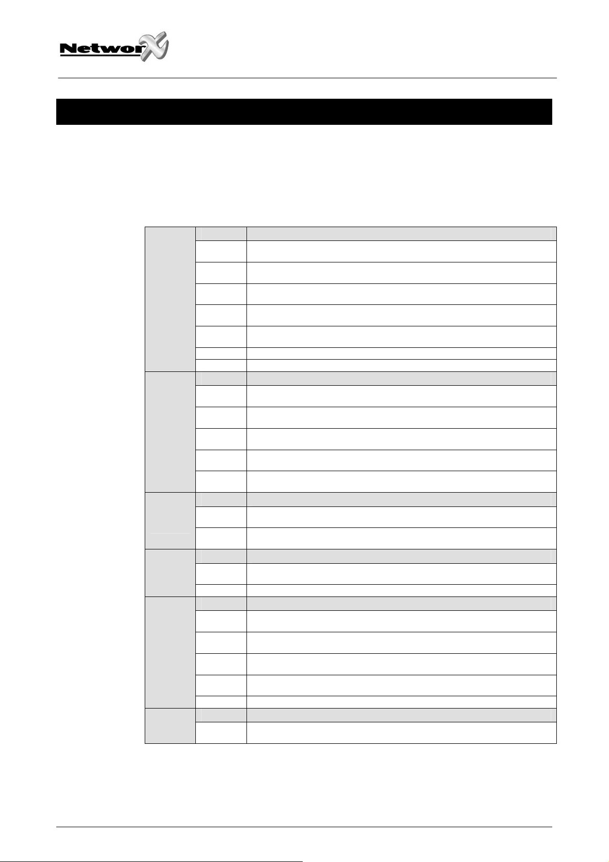
TONES
Indicator tones may be heard at the central station during a two-way session. The
definition of these indicator tones is as follows:
LOW = 400 Hz MID = 1000 Hz HIGH = 1600 Hz
TONE DESCRIPTION
One high tone for 100 msec Time remaining indicator "A”
One mid tone for 100 msec Time remaining indicator “B”
One mid tone for 100 msec
Off for 100 msec
One high tone for 100 msec
One high tone for 100 msec
Off for 100 msec
One mid tone for 100 msec
Off for 100 msec
One high tone for 100 msec
Continuous on/off high tone every 100
msec, will stop after a digit is received
One low tone for 200 msec (if enabled) Anti lock-up
One mid tone for 500 msec Acknowledgement to level change command
One mid tone for 250 msec
Off for 250 msec
One mid tone for 250 msec
Off for 250 msec
One mid tone for 250 msec
One low tone for 100 msec Relay / output turned ON, or
One low tone for 100 msec
Off for 200 msec
One low tone for 100 msec
New alarm alerts for same partition
New alarm alerts for different partition
System waiting for access pin
Error tone
Positive “status” response, or
Partition 1 armed
Relay / output turned OFF, or
Negative “status” response, or
Partition 1 disarmed
NX-534E Installation manual Page 7 09/05/04
Page 8

PROGRAMMING THE NX-534E AUDIO MODULE
Programming the NX-534E via the LED keypad
ENTERING THE PROGRAM MODE
To enter the program mode, press [*]-[8]. At this time, the five functions LED’s (Stay,
Chime, Exit, Bypass and Cancel) will begin to flash. Next, enter the “Go To Program
Code” (factory default is [9]-[7]-[1]-[3]). If the “Go To Program Code” is valid, the “Service”
LED will flash and the five function LED’s will illuminate steady. You are now in the
program mode and ready to select the module to program.
Note: it is impossible to enter program mode if any partition or the system is armed.
SELECTING THE MODULE TO PROGRAM
GE Security
g
Since all modules connected to the NetworX are programmed through the keypad, the
module you are programming should be the first entry. To program the NX-534E module,
enter [6]-[4]-[#]. The [6]-[4] is the module number of the NX-534E and the [#] is the entry
key.
PROGRAMMING A LOCATION
Once the number of the module to be programmed has been entered, the “Armed” LED
will illuminate, indicating it is waiting for a programming location to be entered. Any
location can be accessed by directly entering the desired programming location followed
by the pound [#] key. If the location entered is a valid location, the “Armed” LED will
extinguish, the “Ready” LED will illuminate, and the zone LED’s will show the binary data
for the first segment of this location. While entering new data, the “Ready” LED will begin
flashing to indicate a data change in process. The flashing will continue until the new data
is stored by pressing the [*] key. Upon pressing the [*] key, the keypad will advance to the
next segment and display its data. This procedure is repeated until the last segment is
reached. Pressing the [#] key will exit from this location and the “Armed” LED will
illuminate again waiting for a new programming location to be entered. If the desired
location is the next sequential location, press the [Police] key. If the previous location is
desired press the [Fire] key. If the same location is desired press the [Medic] key. To
review the data in a location, repeat the above procedure, pressing the [*] key without any
numeric data entry. Each time the [*] key is pressed, the programming data of the next
segment will be displayed for review.
EXITING A LOCATION
After the last segment of a location is programmed, pressing the [*] key will exit that
location, turn the “Ready” LED off and the “Armed” LED on. As before, you are now ready
to enter another programming location. If an attempt is made to program an invalid entry
for a particular segment, the keypad sounder will emit a triple error beep (beep, beep,
beep) and remain in that segment awaiting a valid entry.
NX-534E Installation manual Page 8 09/05/04
Page 9

EXITING THE PROGRAM MODE
When all the desired changes in programming have been made, it is time to exit the
program mode. Pressing the [Exit] key will exit this programming level and then return to
the “Select a Module to Program” level. If no additional modules are to be programmed,
pressing the [Exit] key again will exit the program mode. If there is a module to be
programmed, it may be selected by entering its address followed by the [#] key (see
“Selecting the Module To Program” above). The procedure for programming these
devices is the same as for the control panel, except the locations will be for the module
selected.
Note: the timeout for the program mode is 15 minutes.
Programming the NX-534E via the LCD keypad
All steps required for programming are the same as the aforementioned LED keypad. The
LCD keypad display will prompt you for the data required. While in the programming
mode, and not in a location, the number in parenthesis is the location you were previously
changing.
GE Security
g
For example: if the display reads “Enter location, then # (5)”, it is reminding you that
location 5 was the last location you programmed. Refer also to “Programming Data”
which follows.
NX-534E Installation manual Page 9 09/05/04
Page 10

Programming data
Programming data is always one of two types. One type of data is numerical, which can
have values from 0-15 or 0-255 depending on the segment size. The other type of data,
feature selection data, is used to turn features on or off. Use the following procedures
with these two data types:
NUMERICAL DATA: Numerical data is programmed by using the numeric keys of the
system keypad to enter a number from 0-255. To view the data in a location, a binary
process is used. With this process, the LED’s for zones 1 through 8 are utilized, and the
numeric equivalents of their illuminated LED’s are added together to determine the data
in a programming location. The numeric equivalents of these LED’s are as follows:
Zone 1 LED = 1 Zone 2 LED = 2 Zone 3 LED = 4 Zone 4 LED = 8
Zone 5 LED = 16 Zone 6 LED = 32 Zone 7 LED = 64 Zone 8 LED = 128
Example:
GE Security
g
If the numerical data to be programmed in a location is “66”, press [6] - [6] on the keypad.
The LED’s for zone 2 and zone 7 will become illuminated indicating 66 is in that location
(2 + 64 = 66).
Once the data is programmed, press the [*] key to enter the data and advance to the next
segment of that location. After the last segment of a location is programmed, pressing the
[*] key will exit that location, turn the “Ready” LED off and the “Armed” LED on. As before,
you are now ready to enter another programming location. If an attempt is made to
program a number too large for a particular segment, the keypad sounder will emit a triple
beep, indicating an error, and remain in that segment awaiting a valid entry.
Remark: on the LCD keypad, the number in the location will be displayed. For locations
with a maximum of 15, the hexadecimal equivalent will be displayed in parenthesis.
Example: 11 (B) or 14 (E).
FEATURE SELECTION DATA: Feature selection data will display the current condition
(on or off) of eight features associated with the programming location and segment
selected. Pressing a button on the keypad (1 through 8) that corresponds to the “feature
number” within a segment will toggle (on/off) that feature. Pressing any numeric key
between [1] and [8] for selection of a feature will make the corresponding LED illuminate
(feature ON). Press the number again, and the LED will extinguish (feature OFF). You will
see that numerous features can be selected from within one segment. For instance, if all
eight features of a segment are desired, pressing [1] - [2] - [3] - [4] - [5] - [6] - [7] - [8] will
turn on LED’s 1 through 8 as you press the keys, indicating that those features are
enabled.
LCD keypad users note: the numbers of the enabled features will be displayed. However,
the features not enabled will display a hyphen (-).
After the desired setting of features is selected for this segment, press the [*] key. This
will enter the data and automatically advance to the next segment of the location. When
you are in the last segment of a location and press the [*] to enter the data, you will exit
that location. This will now turn the “Ready” LED off and the “Armed” LED on. As before,
you are now ready to enter another programming location.
NX-534E Installation manual Page 10 09/05/04
Page 11

PROGRAMMING THE LOCATIONS
LOCATION 0 - PROGRAMMING FEATURES (8 segments, numerical data)
Segment 1 - Line hold mode or callback mode (default = line hold mode)
This option determines if the NX-534E will operate in the line hold or callback mode when
a listen-in trigger is received. If it is programmed “OFF”, the NX-534E will not release the
line after any communication, which causes a listen-in session to be triggered. The listenin session will start immediately. If this option is programmed “ON”, the NX-534E will
release the line and wait for the central station to call it back before starting a listen-in
session. Default is “OFF”, line hold mode.
Segment 2 - Normal two-way or listen-in only (default = normal two-way)
This feature determines if the NX-534E will operate in the normal two-way mode or listenin only mode. The listen-in only mode will allow the central station to listen to the activity
at the premise. If this option is programmed “OFF”, the NX-534E will function in the
normal two-way mode, and allows the central station to communicate with the person(s)
at the premise. The procedure is controlled from the central station by use of keypresses
on a touch tone telephone. When an alarm occurs during a two-way session, the session
timer is set (refer to location 3, segment 2). If this option is programmed “ON”, the listenin only mode will be functioning.
GE Security
g
Segment 3 - Speaker lockout condition (default = off)
This feature is used to determine the speaker lockout condition. When this option is
“OFF” the automatic speaker lockout is enabled. If this feature is “ON”, the speaker
lockout will be disabled (refer to feature definitions on page 4).
Segment 4 - Microphone “A” start-up selection (default = ON)
This option is used to determine if microphone “A” will be active when the session is
started. Enabling this feature will turn on microphone “A” at start-up. At default, this
feature is enabled.
Segment 5 - Microphone “B” start-up selection (default = ON)
This option is used to determine if microphone “B” will be active when the session is
started. Enabling this feature will turn on microphone “B” at start-up. At default, this
feature is enabled.
Segment 6 - Call in feature answering machine defeat enabled (default = OFF)
This feature will enable the answering machine defeat. When a call-in is made, at least
one ring must be received. The line is picked up and the NX-534E is listening for the PIN
to be entered within the 20-second time limit. If the answering machine defeat is enabled,
even if someone picks up the phone, the NX-534E is still looking for the code. If this
feature is not enabled, the NX-534E will wait for the number of rings programmed in
location 4, segment 4.
Segment 7 – Enable control levels 7 and 8 (default = OFF)
This feature will enable level 7 – status check and level 8 – arming/disarming partition 1.
Segment 8 - Reserved
NX-534E Installation manual Page 11 09/05/04
Page 12

GE Security
LOCATION 1 - CALLBACK ACCESS CODE (default = 123456) (6 segments, feature selection data)
Location 1 contains the access code used to start a listen-in session when the NX-534E
is in a callback mode. The callback access code can be up to a maximum of 6 digits. The
valid entries are 0-15 (10 = *, 11 = , 12 = none, 13 thru 15 = any digit). If less than six
digits are desired, program a “15” at the end of the desired code. If location 1 contains a
“15”, any digit will access the NX-534E. If segment 1 contains a “12”, no access code is
required.
LOCATION 2 - LINE HOLD MODE ACCESS DIGIT (default = 15(F)) (1 segment, numerical data)
Location 2 is used to determine the line-hold access digit. This digit is required to start a
two-way session if line-hold mode is used. Valid entries are: 0 - 15 (10 = *, 11 = #, 12 =
none, 13 thru 15 = any digit). If location 2 contains a “15”, any digit will access the NX534E. If location 2 contains a “12”, no access digit is required.
LOCATION 3 - TIMING OPTIONS (8 segments, numerical data)
g
Segment 1 - Line hold timeout (default = 60 seconds)
Location 3, segment 1 determines how long the NX-534E will wait for the line-hold digit
programmed in location 2 while in the line-hold mode. After a digit is pressed, the timer
will reset. If the digit is not received during this time, the NX-534E will hang-up
(disconnect). This time is programmable from 10 to 255 seconds for each digit.
Segment 2 - New trip hang-up time (default = 20 seconds)
Location 3, segment 2 is used to determine where the NX-534E will set the session timer
when a new trip is received on the same partition during a two-way session. This time is
programmed from 1 to 255 seconds, and will be extended if there is any activity from the
central station. If an alarm occurs in the same partition, pressing a key in this time period
will extend the session timer. If the alarm is in a different partition, the timer will be
reduced automatically and will now allow the timer to be restarted.
Segment 3 - Callback window timer (default = 5 minutes)
Location 3, segment 3 will determine the amount of time, in 1-minute increments, the NX534E will wait for a callback when enabled in location 0, segment 1 or initiated by the
central station (see also “control levels” on page 6). Possible increments are 1 to 255
minutes.
Segment 4 - Wrong pin entries (default = 12)
Location 3, segment 4 determines the maximum number of attempts that can be made to
enter valid access codes for callback and call-in features. Refer to location 0, segments 1
and 6. Valid entries are 6 - 255 attempts. Default is set for 12 attempts.
Segment 5 - Session inactivity hang-up time (default = 90 seconds)
Location 3, segment 5 is used to determine how long the NX-534E will remain on the
phone line with no activity from the central station. This time can be programmed from 30
to 255 seconds.
NX-534E Installation manual Page 12 09/05/04
Page 13

GE Security
Segment 6 - Time remaining tone indicator “A” (default = 20 seconds)
Location 3, segment 6 is used to determine how many seconds will remain when the NX534E sends tone indicator “A” to the central station. This time is used to alert the central
station that the two-way session will be terminated if there is no further activity from the
central station. Valid entries are 1 to 255 seconds.
Segment 7 - Time remaining tone indicator “B” (default = 10 seconds)
Location 3, segment 7 is used to determine how many seconds will remain when the NX534E sends tone indicator “B” to the central station. This time is used to alert the central
station that the two-way session will be terminated if there is no further activity from the
central station. Valid entries are 1 to 255 seconds.
Segment 8 - Anti-lock-up tone time (default = 0 seconds)
Location 3, segment 8 is used to determine at what interval the anti-lock-up tone will be
heard at the central station. This tone is used to prevent noise in an exceptionally loud
environment from interfering with central station’s control of the two-way session. The
possible values are 0-255 seconds. If a 0 is programmed (default), it is disabled and no
tone will be generated.
g
LOCATION 4 - VOLUME / RING CONTROL (4 segments, numerical data)
Segment 1 - Low gain listen-in mode microphone volume (default = 5)
Location 4, segment 1 controls the volume of the microphones when the central station
selects low-gain listen-in mode. The possible value for this location is 0 to 9 (maximum
volume is 9 and minimum is 0).
Segment 2 - High gain listen-in mode microphone volume (default = 9)
Location 4, segment 2 controls the volume of the microphones when the central station
selects high-gain listen-in mode. The possible value for this location is 0 to 9 (maximum
volume is 9, minimum volume is 0).
Segment 3 - Speaker volume (default = 9)
Location 4, segment 3 governs the volume of the speaker when talk is selected by central
station. The possible value for location 4 is 0 to 9 (maximum volume is 9, minimum
volume is 0).
Segment 4 - Number of rings to answer for call-in feature (default = 0)
Location 4, segment 4 determines the number of rings the NX-534E must see before
answering the call while in the call-in mode (refer to location 0, segment 6). Valid entries
are 0 - 9. If a 0 is programmed, it will pick up immediately. A master code is required
within 20 seconds of the line pickup or the line will be disconnected.
NX-534E Installation manual Page 13 09/05/04
Page 14

GE Security
LOCATION 5 – PROGRAMMING X-10 ADDRESS FOR OUTPUT 1 (2 segments, numerical data)
IMPORTANT NOTICE: An X-10 interface module, i.e. NX-507, NX-508 or NX-540
must be present for this feature to work properly.
Segment 1 – Module number (default = 0)
Location 5, segment 1 contains the X-10 module number. Program a number from 0-15 to
represent the corresponding X-10 module number from the following table.
g
Module
Segm. 1
Segment 2 – House code (default = 0)
Location 5, segment 2 contains the X-10 house code. Program a number 0-15 to
represent the corresponding X-10 house code from the following table.
ADDRESS
CODES
LOCATION 6-13 - PROGRAMMING X-10 ADDRESS FOR OUTPUTS 2-9 (2 segments, numerical data)
Locations 6 through 13 are used to program the X-10 address for outputs 2-9. Each
location has 2 segments. Segment 1 contains the module number and segment 2
contains the house code. Refer to the instructions in location 5, as well as the charts
shown above and the programming worksheets.
1 2 3 4 5 6 7 8 9 10 11 12 13 14 15 16
0 1 2 3 4 5 6 7 8 9 10 11 12 13 14 15
X-10
0 = A 4 = E 8 = I 12 = M
1 = B 5 = F 9 = J 13 = N
2 = C 6 = G 10 = K 14 = O
3 = D 7 = H 11 = L 15 = P
NX-534E Installation manual Page 14 09/05/04
Page 15

GE Security
g
NX-534E PROGRAMMING WORKSHEETS
(Defaults are in bold italic text)
LOC PG DESCRIPTION DEFAULT PROGRAMMING DATA
0 11
1 12 CALL-BACK ACCESS CODE
2 12 LINE HOLD DIGIT
3 12
4 13
OPTION FLAGS (Circle numbers to program)
1 OFF: Line hold mode. ON: Call-back mode
2 OFF: Normal two-way. ON: Listen-in only
3 OFF: Automatic speaker lockout. ON: Speaker lockout disabled
4 Microphone A condition at start-up
5 Microphone B condition at start-up
6 ON: Call-in feature answering machine defeat enabled
7 ON: Enable levels 7 & 8
8 Reserved
1 2 3 4 5 6
10 = *, 11 = #, 12 = none, 13 thru 15 = any digit
15 (F)
10 = *, 11 = #, 12 = none, 13 thru 15 = any digit
TIMING OPTIONS
1 Line hold timeout (10-255 seconds) 60
2 New trip hang-up time (1-255 seconds) 20
3 Call-back window (1-255 minutes) 5
4 Maximum number of digits during code entry (2-255) 12
5 Session inactivity hang-up time (30-255 seconds) 90
6 Point for time remaining tone “A” (1-255 seconds) 20
7 Point for time remaining tone “B” (1-255 seconds) 10
8 Anti-lockup tone time (0-255 seconds, 0 = disable) 0
VOLUME / RING CONTROL
1 Low gain microphone volume (0-9) 5
2 High gain microphone volume (0-9) 9
3 Speaker volume (0-9) 9
4 Number of rings for call-in feature (0-9, 0 = disable) 0
NX-534E Installation manual Page 15 09/05/04
Page 16

GE Security
LOC PG DESCRIPTION DEFAULT PROGRAMMING DATA
5 14
6 14
7 14
8 14
9 14
10 14
11 14
12 14
13 14
X-10 ADDRESS FOR OUTPUT 1
1 Module number 0
2 House code 0
X-10 ADDRESS FOR OUTPUT 2
1 Module number 0
2 House code 0
X-10 ADDRESS FOR OUTPUT 3
1 Module number 0
2 House code 0
X-10 ADDRESS FOR OUTPUT 4
1 Module number 0
2 House code 0
X-10 ADDRESS FOR OUTPUT 5
1 Module number 0
2 House code 0
X-10 ADDRESS FOR OUTPUT 6
1 Module number 0
2 House code 0
X-10 ADDRESS FOR OUTPUT 7
1 Module number 0
2 House code 0
X-10 ADDRESS FOR OUTPUT 8
1 Module number 0
2 House code 0
X-10 ADDRESS FOR OUTPUT 9
1 Module number 0
2 House code 0
g
NX-534E Installation manual Page 16 09/05/04
Page 17

GE Security
g
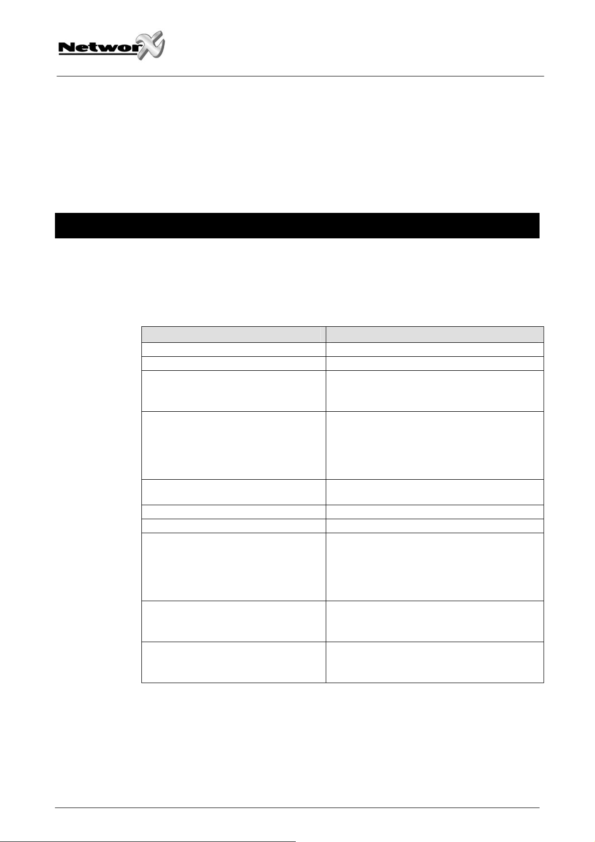
TERMINAL DESCRIPTIONS AND LAYOUT
Terminal Description
1 Connect positive side of microphone #A
2 Connect negative side of microphone #A
3 Connect positive side of microphone #B
4 Connect negative side of microphone #B
POS Connect to the POSITIVE keypad terminal of NetworX control panel
COM Connect to the COM keypad terminal of the NetworX control panel
DATA Connect to the DATA keypad terminal of the NetworX control panel
SPK+
SPKAUDIO
TAP
Connect to the speaker(s). Maximum speaker wire run is 300m. Minimum
speaker rating 5 Watts, 8 Ohms. Do not go below 4 Ohms.
Connect to the audio tap connector on the control panel with the included 5wires wiring harness.
NX-534E Installation manual Page 17 09/05/04
Page 18

GE Security
g
CONNECTION DIAGRAM VS CONTROL PANEL
Check the correct position of PIN1 of the AUDIO TAP in the installation manual of the corresponding
panel.
NX-534E Installation manual Page 18 09/05/04
Page 19

GE Security
g
TECHNICAL SPECIFICATIONS
Power supply:
• nominal:
• minimum/maximum:
Current consumption:
• standby:
• in session:
Telephone: Touchtone
Operating temperature: 0 - 50° C
Dimensions (PCB): 54 x 152 x 18 mm
Weight (PCB): 58 g
12 Vdc via NetworX control panel
9 Vdc - 14 Vdc
50 mA
100 mA
NX-534E Installation manual Page 19 09/05/04
Page 20

GE Security
g
CE DECLARATION
NX-534E Installation manual Page 20 09/05/04
Page 21

GE Security
GE Security
g
g
NX-534E Installation manual Page 21 09/05/04
NX-534E Installation manual Page 21 09/05/04
Page 22

GE Security
GE Security
g
g
NX-534E Installation manual Page 22 09/05/04
NX-534E Installation manual Page 22 09/05/04
Page 23

GE Security
g
NX-534E Installation manual Page 23 09/05/04
Page 24

www.ge-interlogix.com
SLC Distribution is a division of GE Security EMEA bvba
COPYRIGHT ©2004
© GE Security EMEA bvba. All rights reserved. GE Security EMEA bvba grants the right to reprint this
manual for internal use only. GE Security EMEA bvba reserves the right to change information without
notice.
 Loading...