

Interlogix NX-4-FP-12 User Manual
6000 Series PIR
Phone: 800.894.0412 - Fax: 888.723.4773 - Web: www.clrwtr.com - Email: info@clrwtr.com
Model PI6000 - with 30 lb. pet immunity
Model 6000 - with high density (HD) performance lens
Installation Instructions
266
266
267
T T + Ð NC C
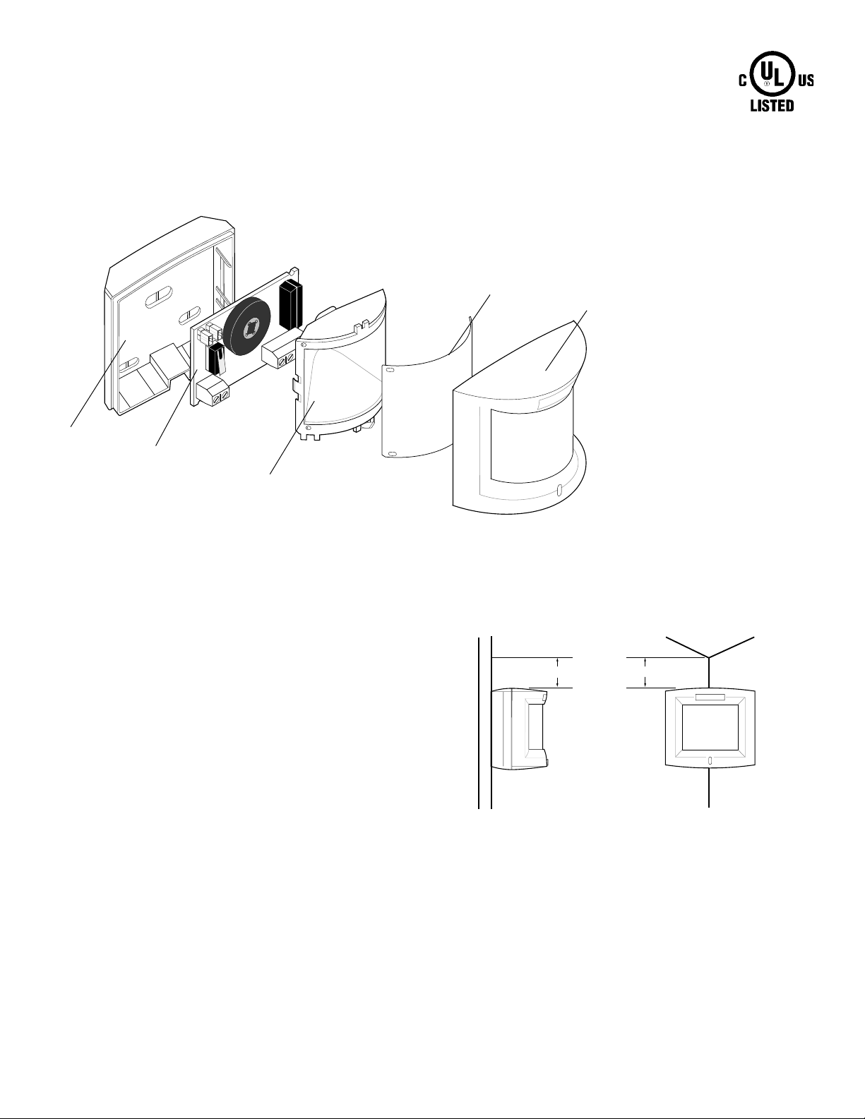
Back housing
Circuit board
Shield
Lens
Front housing
Note
Use a screwdriver to undo the
latch on the bottom of the detector.
Figure 1. Detector (Exploded)
Description
The 6000 Series Passive Infrared Detectors are designed for use in
residential applications. These detectors utilize dual pyroelectric
sensors with jumper selectable pulse count (two- or three-pulse mode).
Advanced signal processing provides high immunity to false trips - RFI,
lightning, vibration, and rapid temperature changes.
An interchangeable, opaque Fresnel lens blocks visible light and
provides the ability to select the best coverage pattern for the site. The
lens is part of a sealed optic enclosure which isolates the pyroelectric
sensor from drafts and insects, common sources of false trips.
The 6000 series comes with a closed loop alarm contact and a closed
loop tamper switch.
.Selecting a Location
• Mount the detector at a height of 7 to 9 feet (2.1 to 2.7m) . See
Mounting Height Settings.
• Mount the detector either flat on the wall or in a corner and at
least 3/8” (0.95cm) from the ceiling. See Figure 2.
• Do not locate the detector where it may be exposed to false
alarm sources, such as:
- heat sources in the field of view
- direct or reflected sunlight
- strong air drafts (fans, air conditioners, etc.) on unit
Flat Wall
3/8”
0.95cm
Figure 2. Mounting
Corner
3/8”
0.95cm
• Do not aim the detector at windows or glass doors.
• Mount the detector on a rigid, vibration-free surface.
• Do not locate the detector on a surface exposed to moisture.
• Do not locate the detector where the ambient temperature is
below 14°F (-10°C) or above 122°F (50°C).
• PIRs require a clear line of sight. Inform end-users not to block the
coverage pattern with inventory, furniture, decorations etc.
6000 Series PIR
E
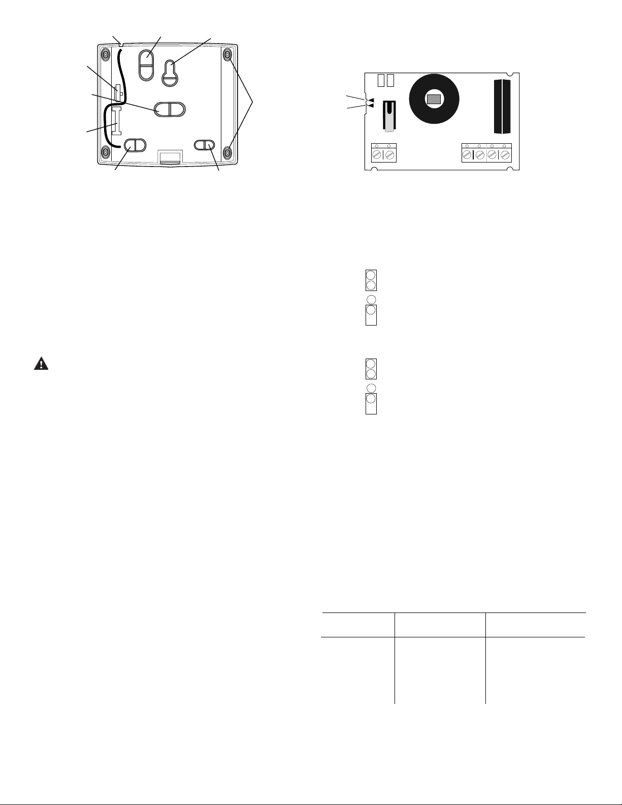
Wire entry hole for
Phone: 800.894.0412 - Fax: 888.723.4773 - Web: www.clrwtr.com - Email: info@clrwtr.com
surface wire runs
Primary wire entry
hole for corner
Primary mounting hole
for flat wall mounting
Locking tab
Center wire
entry hole
Cable strain
relief
Additional wire entry hole
Secondary mounting hole
used to lock down when flat
wall mounting
Figure 3. Back Housing
Mounting
holes for
corner
mounting
Installing the Detector
1. Select an appropriate mounting location.
2. Route wiring to the detector’s location.
3. Open the detector and, after selecting appropriate mounting and
wire entry options, remove the knockouts by depressing from the
inside of the detector in the center of desired knockout (see Figure
3). The circuit board may be removed to facilitate mounting and
removal of knockouts if desired.
A
B
Setting the Jumpers
J3 Pulse Count -
Jumpers
J3 J4
3
2
PULS
J3
J4LED
PET
7/8'
8/9'
TT
Figure 4 . Circuit Board
+–NCCOM
ON = Three-pulse mode
OFF = Two-pulse mode (factory default)
Note
Use two-pulse mode for all residential
applications including pet applications.
Power In
10 to 16 VDC
J4 LED -
CAUTION
ON = LED enabled (factory default)
Y ou must be free of all electricity before handling sensor circuit
boards. T ouch a grounded bare metal surface before touching
OFF = LED disabled
circuit boards or wear a grounding strap. Promptly reinstall the
circuit board when finished with knockout removal and mounting
the back housing.
4. Pull cable through the appropriate knockout and fasten the
detector to the wall.
5. Strip back the outer jacket and individual wires of the cable and
connect the conductors to the proper terminals (see Figure 4). The
alarm contacts are not polarity sensitive.
Note
Use caution not to strip more insulation than needed, approximately 1/4” (0.6cm), so that bare wires do not touch and cause a
short.
Pet Applications
A. For pet applications, the detector should be installed at the standard
7 to 8 feet (2.1 to 2.4m) mounting height. Verify that the circuit board is
properly positioned in the back housing (see Mounting Height Settings).
B. Place the pulse count selection jumper in two-pulse mode (see
Setting the Jumpers).
C. Make sure animals cannot get within 6 feet (1.8m) of the detector’s
line of sight or climb on furniture within 6 feet (1.8m) of the detector.
Note
6. Route the cable through the strain relief located on the far left side
of the back housing (see Figure 3). Snap on the front housing.
7. W alk test the detector and check for desired coverage.
False alarm immunity from any number of small pets and rodents
can be expected as long as the total combined weight does not
exceed 30 lbs. and room temperature does not fall below 50° F
(10° C).
Note
Most units walk test more accurately if the person testing waits
10 seconds between tripping the unit and walking again. This
allows the detector to stabilize between trips.
Mounting Height Settings
The factory setting of the detector is for mounting heights of 7 to 8 feet
(2.1 to 2.4m). For this setting, the locking tab on the back housing is in
the notch by the 7-8’ arrow on the circuit board (position A in Figure 4).
For proper operation at mounting heights above 8 feet (2.4m), the locking
tab must be in the notch by the 8-9’ arrow (position B in Figure 4).
Long Hair Short Hair Not Recommmended
Up to 50 lbs Up to 30 lbs
Cocker Spaniel Basenji Doberman
Eskimo Border T errier Greyhound
Husky French Bulldog Mastiff
Pekinese W elsh Corgi Shepherd
Sheepdog Cats St. Bernard
The pet immunity feature has not been tested by Underwriters
Laboratories Inc.
6000 Series PIR
 Loading...