

Page 1

NX-320E Remote Power Supply
Installation Manual
g
Page 2

Copyright Copyright © 2008 GE Security. All rights reserved.
This document may not be copied in whole or in part or otherwise reproduced without prior
written consent from GE Security except where specifically permitted under US and
international copyright law.
Document number/revision: 466-2299A (April 2008).
Disclaimer The information in this document is subject to change without notice. GE Security (“GE”)
assumes no responsibility for inaccuracies or omissions and specifically disclaims any
liabilities, losses, or risks, personal or otherwise, incurred as a consequence, directly or
indirectly, of the use or application of any of the contents of this document. For the latest
documentation, contact your local supplier or visit us online at www.gesecurity.com.
This publication may contain examples of screen captures and reports used in daily operations.
Examples may include fictitious names of individuals and companies. Any similarity to names
and addresses of actual businesses or persons is entirely coincidental.
Trademarks and patents GE and the GE monogram are registered trademarks of General Electric Company.
Other trade names used in this document may be trademarks or registered trademarks of the
manufacturers or vendors of the respective products.
Intended use Use this product only for the purpose it was designed for; refer to the data sheet and user
documentation. For the latest product information, contact your local supplier or visit us online
at www.gesecurity.com.
FCC compliance This equipment has been tested and found to comply with the limits for a Class B digital device, pursuant to
part 15 of the FCC rules. These limits are designed to provide reasonable protection against harmful interference when the equipment is operated in a residential environment. This equipment generates, uses, and can
radiate radio frequency energy and, if not installed and used in accordance with the instruction manual, may
cause harmful interference to radio communications.
Changes or modifications not expressly approved by the party responsible for compliance could void the
user’s authority to operate the equipment.
EMC directive The European Union directive on electromagnetic compatibility (2004/108/EC) requires non-
European manufacturers to designate an authorized representative in the Community.
Our European representative is GE Security, Kelvinstraat 7, 6003 DH Weert, Nederland.
The European directive Waste Electrical and Electronic Equipment (WEEE) aims to minimize the
impact of electrical and electronic equipment waste on the environment and human health. For
proper treatment, recovery, and recycling, return the equipment marked with this symbol to
your local supplier upon the purchase of equivalent new equipment, or dispose of it in
designated collection points. For more information, visit www.recyclethis.com.
Regulatory
Page 3

Contents
Preface. . . . . . . . . . . . . . . . . . . . . . . . . . . . . . . . . . . . . . . . . . . . . . . . . . . . . . . . . . . . . . . . . . . . . . . . . . . . . . . . . . . . . . . . . 1
Product overview. . . . . . . . . . . . . . . . . . . . . . . . . . . . . . . . . . . . . . . . . . . . . . . . . . . . . . . . . . . . . . . . . . . . . . . . . . . . . . . . 2
Installation . . . . . . . . . . . . . . . . . . . . . . . . . . . . . . . . . . . . . . . . . . . . . . . . . . . . . . . . . . . . . . . . . . . . . . . . . . . . . . . . . . . . . 3
Programming . . . . . . . . . . . . . . . . . . . . . . . . . . . . . . . . . . . . . . . . . . . . . . . . . . . . . . . . . . . . . . . . . . . . . . . . . . . . . . . . . . . 9
Programming worksheets . . . . . . . . . . . . . . . . . . . . . . . . . . . . . . . . . . . . . . . . . . . . . . . . . . . . . . . . . . . . . . . . . . . . . . . 15
Specifications . . . . . . . . . . . . . . . . . . . . . . . . . . . . . . . . . . . . . . . . . . . . . . . . . . . . . . . . . . . . . . . . . . . . . . . . . . . . . . . . . . 19
Contacting us . . . . . . . . . . . . . . . . . . . . . . . . . . . . . . . . . . . . . . . . . . . . . . . . . . . . . . . . . . . . . . . . . . . . . . . . . . . . . . . . . . 20
iii
Conventions used in this document. . . . . . . . . . . . . . . . . . . . . . . . . . . . . . . . . . . . . . . . . . . . . . . . . . . . . . . . . . . . . . . . . . .1
Safety terms and symbols . . . . . . . . . . . . . . . . . . . . . . . . . . . . . . . . . . . . . . . . . . . . . . . . . . . . . . . . . . . . . . . . . . . . . . . . . . . 1
Product contents . . . . . . . . . . . . . . . . . . . . . . . . . . . . . . . . . . . . . . . . . . . . . . . . . . . . . . . . . . . . . . . . . . . . . . . . . . . . . . . . . . . .2
UL requirements. . . . . . . . . . . . . . . . . . . . . . . . . . . . . . . . . . . . . . . . . . . . . . . . . . . . . . . . . . . . . . . . . . . . . . . . . . . . . . . . . . . . .2
Wiring. . . . . . . . . . . . . . . . . . . . . . . . . . . . . . . . . . . . . . . . . . . . . . . . . . . . . . . . . . . . . . . . . . . . . . . . . . . . . . . . . . . . . . . . . . . . . . .4
Battery. . . . . . . . . . . . . . . . . . . . . . . . . . . . . . . . . . . . . . . . . . . . . . . . . . . . . . . . . . . . . . . . . . . . . . . . . . . . . . . . . . . . . . . . . . . . . . 6
Addressing . . . . . . . . . . . . . . . . . . . . . . . . . . . . . . . . . . . . . . . . . . . . . . . . . . . . . . . . . . . . . . . . . . . . . . . . . . . . . . . . . . . . . . . . . .7
LEDs . . . . . . . . . . . . . . . . . . . . . . . . . . . . . . . . . . . . . . . . . . . . . . . . . . . . . . . . . . . . . . . . . . . . . . . . . . . . . . . . . . . . . . . . . . . . . . . . 8
Enrolling . . . . . . . . . . . . . . . . . . . . . . . . . . . . . . . . . . . . . . . . . . . . . . . . . . . . . . . . . . . . . . . . . . . . . . . . . . . . . . . . . . . . . . . . . . . .8
Programming data . . . . . . . . . . . . . . . . . . . . . . . . . . . . . . . . . . . . . . . . . . . . . . . . . . . . . . . . . . . . . . . . . . . . . . . . . . . . . . . . .10
Using an LCD keypad . . . . . . . . . . . . . . . . . . . . . . . . . . . . . . . . . . . . . . . . . . . . . . . . . . . . . . . . . . . . . . . . . . . . . . . . . . . . . . .10
Programming locations . . . . . . . . . . . . . . . . . . . . . . . . . . . . . . . . . . . . . . . . . . . . . . . . . . . . . . . . . . . . . . . . . . . . . . . . . . . . .11
Online resources. . . . . . . . . . . . . . . . . . . . . . . . . . . . . . . . . . . . . . . . . . . . . . . . . . . . . . . . . . . . . . . . . . . . . . . . . . . . . . . . . . . .20
Page 4

NX-320E Remote power Supply
iv
Installation Manual
Page 5

Preface
This is the GE NX-320E Remote Power Supply Installation Manual, which describes the following:
• how to install the power supply; and
• how to program the power supply.
There is also information describing how to contact technical support if you have questions or concerns. T o use
this document effectively, you should have the following minimum qualifications:
• a basic knowledge of NetworX Series products; and
• a basic knowledge of power supplies.
1
Read these instructions and all ancillary documentation entirely before
installing or operating this product. The
most current versions of this and related documentation may be found on our website. Refer to Online
resources on page 20 for instructions on accessing our online publication library.
Note: A qualified service person, complying with all applicable codes, should perform all required hardware installation.
Conventions used in this document
The following conventions are used in this document:
Bold Menu items and buttons.
Italic Emphasis of an instruction or point; special terms.
File names, path names, windows, panes, tabs, fields, variables, and other GUI elements.
Titles of books and various documents.
Blue italic (Electronic version.) Hyperlinks to cross-references, related topics, and URL addresses.
Monospace Text that displays on the computer screen.
Programming or coding sequences.
Safety terms and symbols
These terms may appear in this manual:
CAUTION: Cautions identify conditions or practices that may result in damage to the equipment or other property.
WARNING: Warnings identify conditions or practices that could result in equipment damage or serious personal injury.
Page 6

NX-320E Remote Power Supply
2
Installation Manual
Product overview
The NX-320E is a microprocessor-controlled remote power supply module for the NetworX control panels.
The module has three programmable outputs (A, B, C) and one programmable style Y bell output. You can add
up to eight power supply modules for a total of 32 outputs. You can use the A, B, and C programmable outputs
as auxiliary power, for smoke detectors and sirens. (See Specifications on page 19.) Each power supply module
has a tamper terminal that can be used to supervise the metal enclosure. Do not use more than 2500 ft. of wire
from the NX-320E to all outgoing devices.
Product contents
The NX-320E Remote Power Supply includes the following:
•Board
• Board guides
• Transformer
• Diodes (2), black wrap is for fire installation
• Resistors (2), white wrap for fire installation
You will also need the following items that are not included with the NX-320E:
• 22 gauge 4-conductor wire (Table 1 on page 4)
• Battery (Table 3 on page 6)
UL requirements
The NX-320E meets the Underwriters Laboratories (UL) standards, including the following:
• UL365 Police Station Connected Burglar Alarm Units and Systems
• UL609 Local Burglar Alarm Units and Systems
• UL864 Control Units for Fire-protective Signaling Systems
• UL985 Household Fire W a rning Systems
• UL1023 Household Burglar Alarm Systems
• UL1610 Central Station Burglar Alarm Units
When the NX-320E is part of a UL commercial fire security system, this unit is compatible with the following:
• NX-148E-CF LCD keypad
• NX-216E zone expander
• NX-507E relay expander
• 13-474 horn/strobe 15-75 CD (for proper strobe operation, change Location 6, Segment 1 from 16 to
13)
For UL installations, the Class II, Class III, and power-limited fire alarm circuits must be installed using FPL,
FPLP, FPLR, CLIII, CLIIIR, or CLIIIP, or substitute cable permitted by National Electrical Code ANSI/
NFP A 70. If you have Class II, Class III, and power-limited fire alarm circuit conductors that extend beyond the
cable jacket, separate the wires by a 0.25 in. from all other conductors or use nonconducting tubing.
Page 7
Installation
There are several two-holed insertion points inside the enclosure so you can install the module either
horizontally or vertically. The insertion points have a large hole and a smaller hole.
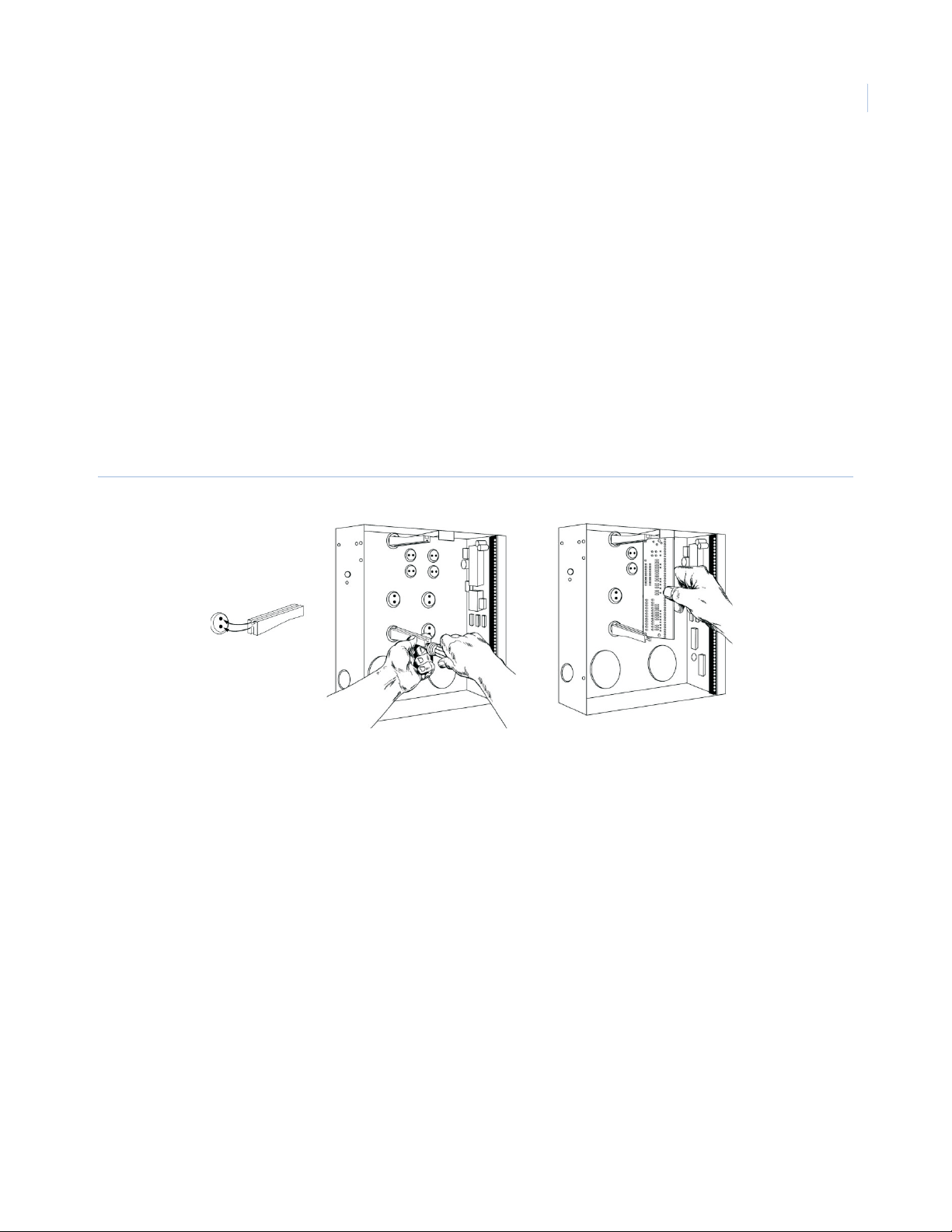
To mount the board in an enclosure, see Figure 1 and do the following:
1. Place a black plastic PCB guide in the top insertion point, grooved edge downward. The half-moon
protrusion will be in the large hole. Do not use excessive force.
2. Insert one of the included screws into the smaller hole (from the inside of the can) to secure it in place.
A screwdriver should reach through the notch that runs the length of the guide to tighten the screw.
3. Position the other PCB guide opposite the first (grooved edge up) and placed in the lower insertion
point, using the same procedure. Once you mount the guide, screw it in securely.
4. Slide the board into the grooves of both guides. The PC board should slide freely.
Figure 1. Board installation
3
Page 8
NX-320E Remote Power Supply
4
Installation Manual
Wiring
When you connect the unit, do the following:
• For UL commercial fire installations, use at least 18 AWG for all field wiring. We do not recommend
shielded wire.
• Use a 16.5 VAC 50 VA / 120 V, 60 Hz hard-wired transformer (GE Security #T-0002).
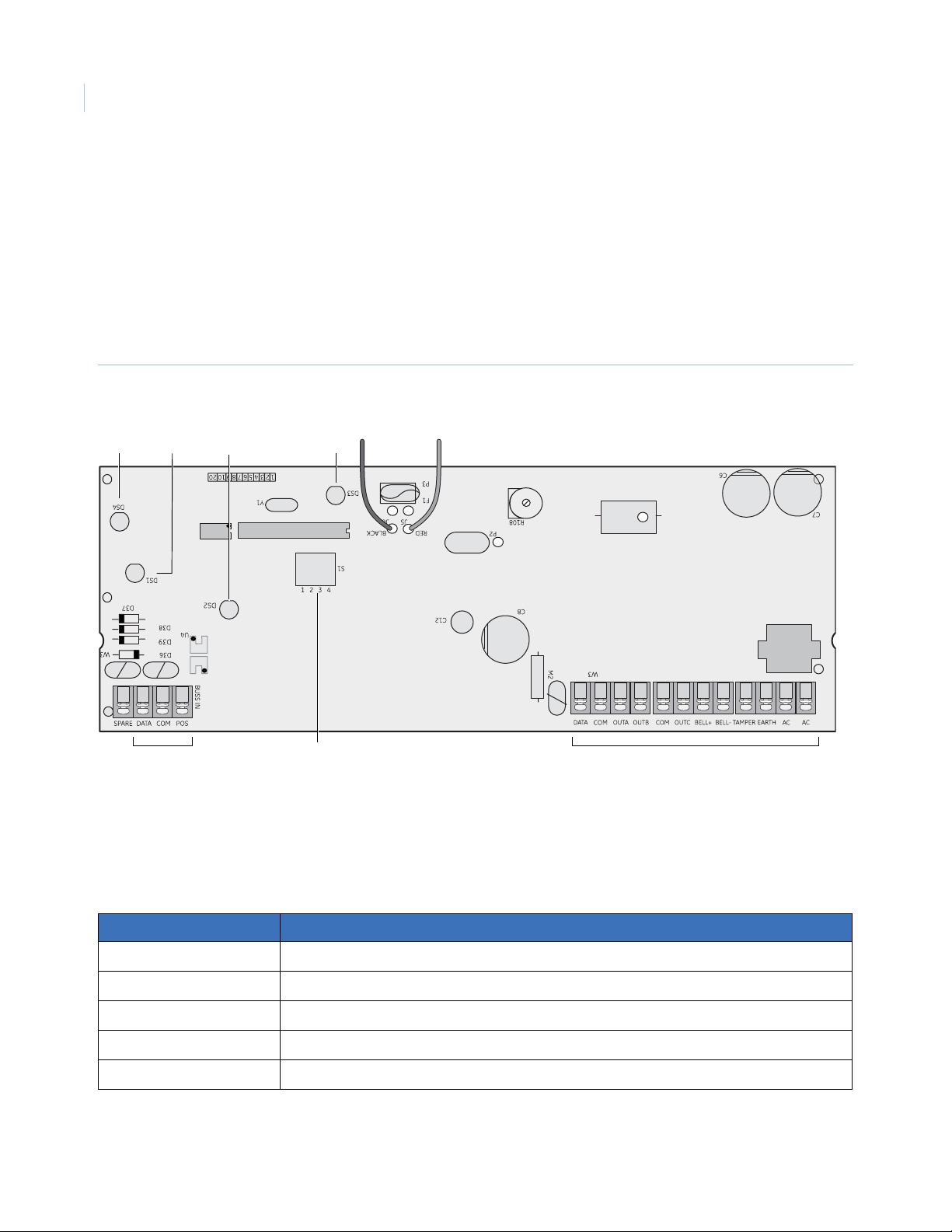
Do not connect multiple power supply modules in a series (cascaded). The board is wrapped in bubble wrap.
Unwrap it so you can orient yourself as you review Figure 2.
Figure 2. Board connections
Battery wires
LED 4
LED 1
LED 3LED 2
T1
In terminals
DIP switch block
Expansion terminals
Wiring requirements
Use Table 1 to calculate your wiring requirements. We do not recommend shielded wire. For UL Commercial
Fire installations, a minimum of 18 AWG must be used for all field-wiring applications.
Table 1. Wiring requirements
Length (in ft.) Wire gauge (when connected to NetworX panel)
400 24
500 24
1000 24
2000 22
2500 20
Page 9

Connections
Connect the terminals described in Table 2. The total wire run from the control panel to all devices, including
the NX-320E is 2500 feet.
Table 2. Terminal descriptions
Terminal Description
Control panel terminals
DATA Connect to the control panel’s Data terminal. This terminal is the incoming data-signaling terminal to
the NX-320E module.
COM Connect to the control panel’s Common terminal. This terminal supplies the common side of the power
to the NX-320E module.
POS Connect to the control panel’s Aux power + terminal. This terminal supplies power to the NX-320E
module.
Accessory terminals
DATA Connect the outgoing data-signaling terminal for bus extension.
5
COM Common terminal for any device powered from the NX-320E.
Out A and B
COM
OUT C
a
a
a
Connect programmable output current limited to 1.5 A.
Connect any device powered from the NX-320E.
Connect programmable output current limited to 1.5 A.
BELL+ and BELL- Connect bell as in Figure 3 on page 6. The current is limited to 2.5 A.
TAM Connect an optional Tamper terminal. To use this feature, connect the normally closed tamper switch
between this terminal and COM. If DIP switch 4 is off, this feature is not used.
EARTH Connect earth ground.
AC Connect AC input. Connect to a 16.5 V 50 VA Class II UL approved transformer.
a. The total current on the NX-320E should not exceed 2.0 A.
Page 10

NX-320E Remote Power Supply
6
Installation Manual
Bell output connections
The bell output (Figure 3) is voltage only and is pulsed (temporal) during a fire alarm and steady during a
burglar alarm. GE includes the diode (#EOL-D5400) and resistor (#EOL-33) necessary to complete the
installation. If the audible device is commercial fire listed, you do not need the diode (#EOL-D5400).
Remember to use the black-wrapped diode and white-wrapped resistor for fire installations. The bell circuit
current is rated at 2.5 A maximum.
Figure 3. Bell output wiring
T1
+
-
Diode
Resistor
Power
Battery
The battery is not included with the NX-320E. You need the battery for emergency backup.We recommend the
Yuasa NP18-12B battery (12 V, 17 Ah). The battery capacity for emergency standby should be at least 24
hours. UL installations must use at least one 17.2 Ah battery for 24 hours of backup. The control panel draws
50 mA standby power.
Use Table 3 to ca lculate your battery requirements..
Table 3. Battery calculation table
Standby time Total auxiliary current Standby battery capacity Alarm current
24 hours 1.9 A
1.25 A
600 mA
48 hours 900 mA
600 mA
300 mA
51 Ah
34 Ah
17 Ah
51 Ah
34 Ah
17 Ah
600 mA
1 A
1 A
1 A
1 A
1 A
72 hours 600 mA
400 mA
200 mA
51 Ah
34 Ah
17 Ah
1 A
1 A
1 A
Page 11

To install the battery, connect the red and black wires to your battery (Figure 4).
Figure 4. Battery connection
7
Red wire
+
12 volt battery
not included
-
Black wire
Addressing
Use the DIP switches to set the module address (84 to 91). Table 4 shows the address settings. Use DIP switch
4 to set the tamper feature: On = enabled, Off = disabled.
Table 4. Addresses
Address DIP switch 1 DIP switch 2 DIP switch 3
84 Off Off Off
85 On Off Off
86 Off On Off
87 On On Off
88 Off Off On
89 On Off On
90 Off On On
91 On On On
Page 12

NX-320E Remote Power Supply
8
Installation Manual
LEDs
The power supply module has four red LEDs to provide status information. See Figure 2 and Table 5 for
locations and descriptions of the LEDs.
Table 5. LED connections
LED Board ID Description
LED 1 DS1 Flashes when data is transmitted from the NX-320E.
LED 2 DS2 Flashes when data is transmitted into the NX-320E.
LED 3 DS3 Flashes during normal operation.
LED 4 DS4 Glows dimly when connected to the NetworX panel. (See Specifications on page 19).
Enrolling
The NetworX control panel can locate and store the presence of keypads, zone expanders, and wireless
receivers, and other modules connected to the data terminal. This allows these modules to be supervised by the
control panel. T o enroll the modules, enter NetworX control panel program mode and then exit program mode.
The panel automatically enrolls the devices. The process takes about 12 seconds. During this time, the Service
LED illuminates and you cannot enter user codes. If you enroll a module that the system cannot detect, the
Service LED will illuminate.
Page 13

Programming
You can use an LED keypad or LCD keypad to program the module.
Using an LED keypad
To program the module with an LED keypad, do the following:
1. Enter *, 8. All of the function key LEDs will begin to flash.
2. Enter the Go To Program code (default is 9713). If the code is valid, the Service LED will flash, and
the function LEDs will illuminate steadily , indicating you should enter the device to program.
3. T o enter a module address, press 8, 6, # (See Table 4 on page 7). The Armed LED will illuminate while
it is waiting for a programming location to be entered.
4. Enter the programming location followed by the # key. The Armed LED will begin to flash. If this is a
valid location, the Armed LED will extinguish, the Ready LED will il luminate, and the binary data for
the first segment of this location will appear on the Zone LED.
5. To change the data, enter the data followed by the * key. The location will automatically increment to
the next segment. The data for that segment will display . Repeat the procedure until the system reaches
the last segment.
9
6. To exit this location without changing the data, press the # key.
7. To review the data, press the * key but do not enter the data. Each time you press *, the next segment
displays. After you program the last segment for a location, press * to exit that location. The system
will turn the Ready LED off and the Armed LED on. As before, you are now ready to enter another
programming location.
Note: If you attempt to program an invalid entry for a particular segment, the keypad sounder will emit a triple-beep and
remain in that segment until there is a valid entry.
8. To enter another location, do one of the following:
• Enter the location number followed by the # key.
• Press Police for the next location.
• Press Fire for the previous location.
• Press Auxiliary for the same location.
9. Press Exit to exit this module. Press Exit again, to completely exit program mode.
Page 14

NX-320E Remote Power Supply
10
Installation Manual
Programming data
When you program data, you set numerical data or feature selection data.
Numerical data. Use the numeric keys of the system keypad with a number from 0 to 255. The system
uses a binary process, so to view the data, look at the LEDs for zones 1 through 8 and see which ones are
illuminated. When you add the illuminated LEDs together , you get the programming location. The numeric
equivalents of these LEDs include the following:
Zone 1 LED = 1
Zone 2 LED = 2
Zone 3 LED = 4
Zone 4 LED = 8
For example, if you want to program 66 in a location, press 6, 6 on the keypad. The LEDs for Zone 2 and
Zone 7 will illuminate, which indicates 66 is in that location (2 + 64 = 66). Once you program the data,
press the * key to enter the data and advance to the next segment for that location. After the last segment of
a location is programmed, you can press the * key to exit that location and turn the Ready LED off and the
Armed LED on. You can now enter another programming location. If you attempt to program a number
that is too large, the keypad sounder will emit a triple-beep and will await a valid entry.
Feature selection data. Feature selection data will display the current condition (on or off) related to the
eight features associated with the programming location and segment you selected. Press a button on the
touchpad (1 to 8) that corresponds to the f ea t ure number within a segment you require. That feature
number will illuminate (feature on). Press the number again, and the LED will extinguish (feature off). You
will see that you can select numerous features from within one segment. For instance, if you require all
eight segments, press 1, 2, 3, 4, 5, 6, 7, 8. LEDs 1 through 8 will illuminate as you press the keys, to
indicate that those features are enabled.
Zone 5 LED = 16
Zone 6 LED = 32
Zone 7 LED = 64
Zone 8 LED = 128
Using an LCD keypad
The steps to programming using an LCD keypad are identical to Using an LED keypad on page 9. The only
difference is that the LCD keypad will prompt you for the data required. In programming mode, the number in
parentheses is the location you previously changed. For example, if the display reads Enter location,
then # (2), the system is telling you that Location 2 was the last location you programmed. In feature
selection data, the numbers of the enabled features are displayed. The features not enabled will include a
hyphen (-).
Page 15

Programming locations
Location 0 - event and time for output A. This location has two segments of numerical data. To
program the event and time set the following:
• Segment 1. Select the event that triggers Output A. See Table 6 for events you can trigger.
• Segment 2. Select how long an output will remain activated when an output triggers. For a location
that is programmed as zero, the output will follow the event.
Table 6. Event and time programming for Output A
# Event # Event # Event
0 Always on 11 Smoke power reset 22 Disarmed
1 AC fail (control or exp.)
2 Low battery (control or exp.) 13 Steady siren 24 Not ready to arm
3 Dynamic battery test time 14 Any siren 25 Fire
4 Listen in 15 Steady siren (temporal) 26 Fire trouble
a
12 Yelping siren 23 Ready to arm
11
5 Line seizure 16 Any siren (temporal) 27 Chime
6 Telephone line fault 17 Alarm memory 28 Beeping keypad
7 Program mode 18 Entry 29
8 Overcurrent (control or exp.) 19 Exit 30
9 Box tamper (control or exp.) 20 Entry or exit 31
10 Siren tamper (control or exp.) 21 Armed 32
a. Does not follow AC fail delay time.
b. If set to the following condition, these events will be one second.
b
Aux 1 keypad function
b
Aux 2 keypad function
b
Panic keypad function
b
Code entry (set in loc 8–17)
Page 16

NX-320E Remote Power Supply
12
Installation Manual
Location 1 - special features for output A. This location has two segments of feature selection data to
program special features for output A (see Table 7)
Table 7. Special features for output
Number Segment 1 output Segment 2 event
1 On for minutes; Off if output times in seconds. On to activate when it occurs in Partition 1.
2 On if latched until a code is entered; Off for timed. On to activate when it occurs in Partition 2.
3 On to stop time when a code is entered. On to activate when it occurs in Partition 3.
4 On for inverted output. On to activate when it occurs in Partition 4.
5 On to disable during listen-in (only events 12 to 16). On to activate when it occurs in Partition 5.
6 Reserved. On to activate when it occurs in Partition 6.
7 Reserved. On to activate when it occurs in Partition 7.
8 Reserved. On to activate when it occurs in Partition 8.
Location 2 - event and time for output B. This location has two segments of numerical data to program
the event and time for output B.
.
• Segment 1. Select the event that triggers output B (See Table 6 on page 11).
• Segment 2. Select how long an output will remain activated when an output triggers. For a
location that is programmed as zero, the output will follow the event.
Location 3 - special features for output B. This location has two segments of feature selection data to
program special features for output B (see Table 7).
Location 4 - event and time for output C. This location has two segments of numerical data to program
the event and time for output C.
• Segment 1. Select the event that triggers output C. (See Table 6 on page 11).
• Segment 2. Select how long an output will remain activated when an output triggers. For a
location that is programmed as zero, the output will follow the event.
Location 5 - special features for output C. This location has two segments of feature selection data to
program special features for output C (see Table 7).
Location 6 - event and time for the bell output. This location has two segments of numerical data to
program the event and time for the bell output.
• Segment 1. Select the event that triggers the bell output. (See Table 6 on page 11).
• Segment 2. Select how long an output will remain activated when an output triggers. For a
location that is programmed as zero, the output will follow the event.
Location 7 - special features for the bell output. This location has two segments of feature selection
data to program special features for the bell output (see Table 7).
Page 17

Location 8 - codes 1 to 10, output enable. This location has 10 segments of feature selection data. When
you activate outputs with a user code (event #30), you can use Location 8 to restrict certain codes from
activating certain outputs. Segment 1 corresponds to user 1; Segment 10 corresponds to user 10. The LEDs
correspond to outputs A to C (see Table 8)..
Table 8. Output enable
LED Description
1 On if code will activate Output A; Off if it will not.
2 On if code will activate Output B; Off if it will not.
3 On if code will activate Output C; Off if it will not.
4Reserved.
Location 9 - codes 11 to 20, output enable. This location has 10 segments of feature selection
data.When you activate outputs with a user code (event #30), yo u can use Location 9 to restrict certain
codes from activating certain outputs. Segment 1 corresponds to user 11; Segment 10 corresponds to user
20. The LEDs correspond to outputs A to C (see Table 8).
13
Location 10 - codes 21 to 30, output enable. This location has 10 segments of feature selection data.
When you activate outputs with a user code (event #30), you can use Location 10 to restrict certain codes
from activating certain outputs. Segment 1 corresponds to user 21; Segment 10 corresponds to user 30. The
LEDs correspond to outputs A to C (see Table 8).
Location 11 - codes 31 to 40, output enable. This location has 10 segments of feature selection data.
When you activate outputs with a user code (event #30), you can use Location 11 to restrict certain codes
from activating certain outputs. Segment 1 corresponds to user 31; Segment 10 corresponds to user 40. The
LEDs correspond to outputs A to C (see Table 8).
Location 12 - codes 41 to 50, output enable. This location has 10 segments of feature selection data.
When you activate outputs with a user code (event #30), you can use Location 12 to restrict certain codes
from activating certain outputs. Segment 1 corresponds to user 41; Segment 10 corresponds to user 50. The
LEDs correspond to outputs A to C (see Table 8).
Location 13 - codes 51 to 60, output enable. This location has 10 segments of feature selection data.
When you activate outputs with a user code (event #30), you can use Location 13 to restrict certain codes
from activating certain outputs. Segment 1 corresponds to user 51; Segment 10 corresponds to user 60. The
LEDs correspond to outputs A to C (see Table 8).
Location 14 - codes 61 to 70, output enable. This location has 10 segments of feature selection data.
When you activate outputs with a user code (event #30), you can use Location 14 to restrict certain codes
from activating certain outputs. Segment 1 corresponds to user 61; Segment 10 corresponds to user 70. The
LEDs correspond to outputs A to C (see Table 8).
Location 15 - codes 71 to 80, output enable. This location has 10 segments of feature selection data.
When you activate outputs with a user code (event #30), you can use Location 15 to restrict certain codes
from activating certain outputs. Segment 1 corresponds to user 71; Segment 10 corresponds to user 80. The
LEDs correspond to outputs A to C (see Table 8).
Page 18

NX-320E Remote Power Supply
14
Installation Manual
Location 16 - codes 81 to 90, output enable. This location has 10 segments of feature selection data.
When you activate outputs with a user code (event #30), you can use Location 16 to restrict certain codes
from activating certain outputs. Segment 1 corresponds to user 81; Segment 10 corresponds to user 90. The
LEDs correspond to outputs A to C (see Table 8 on page 13.)
Location 17 - codes 91 to 99, output enable. This location has nine segments of feature selection data.
When you activate outputs with a user code (event #30), you can use Location 17 to restrict certain codes
from activating certain outputs. Segment 1 corresponds to user 91; Segment 9 corresponds to user 99. The
LEDs correspond to outputs A to C (see Table 8 on page 13).
Location 18 - A/C delay and dynamic battery test. This location has two segments of feature selection
data. Use this location to enable the A/C delay and the dynamic battery test, both of which are timed in
minutes. The factory default is 5-0, meaning the A/C power will be off for 5 minutes before a report is sent
or a Service light will illuminate, and the dynamic battery test is disabled (0 minutes). If you want the A/C
delay to be 8 minutes and the dynamic battery test to be 3 minutes, you would program 8, 3.
Location 19 - device options. This location has eight segments of feature selection data. Use this location
to enable various system features of the power supply module. The LEDs are described in Table 9.
Table 9. Output enable
LED Description
1 On for AC report always sent; Off follows control.
• If On, an AC fail report will be sent if power is lost for the time programmed in Location 18.
• If Off, the report will only be sent if the control panel has not sent an AC power lost report, and AC fail
report is enabled in Location 37 of the panel.
2On for enables periodic battery test . Enables battery missing every 30 seconds.
3 On enables low battery reporting. If enabled, the power supply module will report a low battery warning
to the central station.
4On enables siren tamper/trouble reporting. If enabled, the power supply module will report a siren tamper
to the central station.
5 to 8 Reserved.
Page 19

Programming worksheets
Use Table 10 to program Locations 1 to 7. Use the Data column to enter your programming information.
Table 10. Worksheet for Locations 0 to 7
Location Description Default Data
0
1
2
3
4
5
6
Location 0 - event and time for output A on page 11 0, 10
Location 1 - special features for output A on page 12
Segment 1
1. On if timed in minutes; Off if timed in seconds.
2. On if latched until code is entered; Off for timed.
3. On if output should stop time when a code is entered (default).
4. On for inverted output.
5. On disables output during listen-in.
6-8. Reserved
Segment 2
1 = Partition 1 2 = Partition 2 3 = Partition 3 4 = Partition 4
5 = Partition 5 6 = Partition 6 7 = Partition 7 8 = Partition 8
Location 2 - event and time for output B on page 12 0, 10
Location 3 - special features for output B on page 12
Segment 1
1. On if timed in minutes; Off if timed in seconds.
2. On if latched until code is entered; Off for timed.
3. On if output should stop time when a code is entered (default).
4. On for inverted output.
5. On disables output during listen-in.
6-8. Reserved
Segment 2
1 = Partition 1 2 = Partition 2 3 = Partition 3 4 = Partition 4
5 = Partition 5 6 = Partition 6 7 = Partition 7 8 = Partition 8
Location 4 - event and time for output C on page 12 0, 10
Location 5 - special features for output C on page 12
Segment 1
1. On if timed in minutes; Off if timed in seconds.
2. On if latched until code is entered; Off for timed.
3. On if output should stop time when a code is entered (default).
4. On for inverted output.
5. On disables output during listen-in.
6-8. Reserved
Segment 2
1 = Partition 1 2 = Partition 2 3 = Partition 3 4 = Partition 4
5 = Partition 5 6 = Partition 6 7 = Partition 7 8 = Partition 8
Location 6 - event and time for the bell output on page 12 16, 0
3
1, 2, 3, 4,
5, 6, 7, 8
3
1, 2, 3, 4,
5, 6, 7, 8
4
1, 2, 3, 4,
5, 6, 7, 8
15
Page 20

NX-320E Remote Power Supply
16
Installation Manual
Table 10. Worksheet for Locations 0 to 7 (continued)
Location Description Default Data
7
Location 7 - special features for the bell output on page 12
Segment 1
1. On if timed in minutes; Off if timed in seconds.
2. On if latched until code is entered; Off for timed.
3. On if output should stop time when a code is entered (default).
4. On for inverted output.
5. On disables output during listen-in.
6-8. Reserved
Segment 2
1 = Partition 1 2 = Partition 2 3 = Partition 3 4 = Partition 4
5 = Partition 5 6 = Partition 6 7 = Partition 7 8 = Partition 8
3, 5
1, 2, 3, 4,
5, 6, 7, 8
Page 21

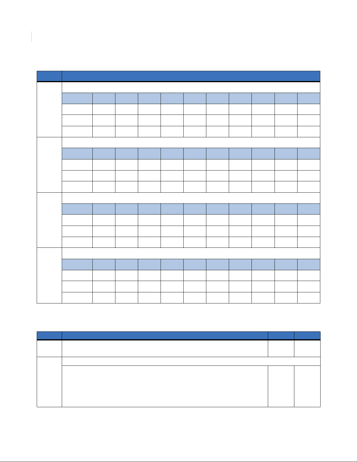
Use Table 11 to program Locations 8 to 17. Circle the numbers to indicate your programming information.
Table 11. Worksheet for Locations 8 to 17
Location Description
17
8
9
10
11
Location 8 - codes 1 to 10, output enable on page 13
User 1 2 3 4 5 6 7 8 9 10
Output #A1111111111
Output #B2222222222
Output #C3333333333
Location 9 - codes 11 to 20, output enable on page 13
User 11 12 13 14 15 16 17 18 19 20
Output #A1111111111
Output #B2222222222
Output #C3333333333
Location 10 - codes 21 to 30, output enable on page 13
User 21 22 23 24 25 26 27 28 29 30
Output #A1111111111
Output #B2222222222
Output #C3333333333
Location 11 - codes 31 to 40, output enable on page 13
12
13
User 31 32 33 34 35 36 37 38 39 40
Output #A1111111111
Output #B2222222222
Output #C3333333333
Location 12 - codes 41 to 50, output enable on page 13
User 41 42 43 44 45 46 47 48 49 50
Output #A1111111111
Output #B2222222222
Output #C3333333333
Location 13 - codes 51 to 60, output enable on page 13
User 51 52 53 54 55 56 57 58 59 60
Output #A1111111111
Output #B2222222222
Output #C3333333333
Page 22
NX-320E Remote Power Supply
18
Installation Manual
Table 11. Worksheet for Locations 8 to 17 (continued)
Location Description
14
15
16
17
Location 14 - codes 61 to 70, output enable on page 13
User 61 62 63 64 65 66 67 68 69 70
Output #A1111111111
Output #B2222222222
Output #C3333333333
Location 15 - codes 71 to 80, output enable on page 13
User 71 72 73 74 75 76 77 78 79 80
Output #A1111111111
Output #B2222222222
Output #C3333333333
Location 16 - codes 81 to 90, output enable on page 14
User 81 82 83 84 85 86 87 88 89 90
Output #A1111111111
Output #B2222222222
Output #C3333333333
Location 17 - codes 91 to 99, output enable on page 14
User 91 92 93 94 95 96 97 98 99
Output #A111111111
Output #B222222222
Output #C333333333
Use Table 12 to program Locations 18 and 19. Use the Data column to enter your programming information.
Table 12. Worksheet for Locations 18 and 19
Location Description Default Data
18
19
Location 18 - A/C delay and dynamic battery test on page 14 5
Location 19 - device options on page 14
1. On for AC report always sent; Off follows control
2. On enables periodic battery test
3. On enables low battery reporting
4. On enables siren tamper/trouble reporting
5 to 8. Reserved.
0
2, 3, 4
Page 23

Specifications
Dimensions 2.0 × 4.0 in.
Current draw
AC input
Standby
Transformer
Auxiliary power
VA Limited to 2.0 A
Battery 51 Ah for 24 hours of battery backup 5 to 17 Ah in parallel
Operating temperature 32 to 120°F (0 to 49°C)
Shipping weight 8 lb. (3.63 kg)
Compatible control panels NX-8 48 Zone Household Fire & Burglary or NX8V2 Commercial Burglary Control
120 V 60 Hz, 650 mA
10 mA VA
16.5 VAC 50 VA
NX-8-CF 48 Zone Commercial Fire Control
NX-8E 192 Zone Household Fire & Burglary, Commercial Burglary Control
NX-8E-CF. 192 Zone Commercial Fire Control
19
Page 24

NX-320E Remote Power Supply
20
Installation Manual
Contacting us
For help installing, operating, maintaining, and troubleshooting this product, refer to this document and any
other documentation provided. If you still have questions, contact us during business hours (Monday through
Friday, excluding holidays, between 5 a.m. and 5 p.m. Pacific Time).
Table 13. Technical support
North America Latin America
T: 888 GE Security (888.437.3287) Toll-free in the US,
Puerto Rico, and Canada.
503.885.5700 outside the toll-free area.
F: 561.998.6232 (Boca Raton tech support)
E: nstechsrv@ge.com
:gesecurity.customerservice@ge.com
Australia, New Zealand China, India, Singapore, Taiwan, Southeast Asia
E: techsupport@gesecurity.com.au E: ges.asiatechservice@ge.com
Note: Be ready at the equipment before calling.
T: 305.593.4301
F: 305.593.4300
E: InfraSec.TechnicalServicesLatinAmerica@ge.com
InfraSecCustomerService.LatinAmerica@ge.com
Europe, Middle East, and Africa
W: At www.gesecurity.eu, select Customer Support.
Online resources
Here are some useful links on our website www.gesecurity.com:
Online library. From the Customer Support menu, select the Resource Library link. After you register
and log on, you may search for the documentation you need.
Training. T o view any availab le online trainin g for GE Security products, select the Training link. (Online
training is not available for all products.)
Warranty and terms information. From the Customer Support menu, select Return and Warranty
Policy Statement or Terms and Conditions Policy Statement.
Customer service and technical support. From the Customer Support menu, select Customer Service or
Technical & Application. Select the appropriate product category for the contact information or use the
menu to select a location outside the US.
1
1. Many GE documents are provided in English only as PDFs. To read these documents, you will need Adobe Reader, which you
can download free from Adobe’s website at www.adobe.com.
 Loading...