

Page 1

NX-2192E PINPOINT SYSTEM
INSTALLATION MANUAL
TABLE OF CONTENTS
GENERAL DESCRIPTION.......................................................................................................................... 2
1.
2. INSTALLATION .......................................................................................................................................... 2
3. DEVICE ADDRESS CONFIGURATION...................................................................................................... 2
4. TERMINAL DESCRIPTIONS ...................................................................................................................... 2
5. WIRING DIAGRAM..................................................................................................................................... 3
6. MAXIMUM NUMBER OF DEVICES PER WIRE RUN................................................................................ 4
7. ENROLLING THE PINPOINT SYSTEM...................................................................................................... 4
8. PROGRAMMING THE MODULE................................................................................................................ 4
9. PROGRAMMING SEQUENCE EXAMPLE................................................................................................. 4
10. PROGRAMMING LOCATION GUIDE ........................................................................................................ 5
11. BATTERY CALCULATION WORKSHEET................................................................................................. 8
12. NX-2192E PROGRAMMING WORKSHEETS ............................................................................................ 9
13. APPENDIX 1 PINPOINT ADDRESS WORKSHEET............................................................................. 40
14. UL & CE NOTICES ................................................................................................................................... 44
15. SPECIFICATIONS..................................................................................................................................... 44
© 2004 GE All rights reserved. Printed in the USA.
NetworX
These instructions do not purport to cover all details or variations in equipment nor to provide ev ery possible contingency to be met during
installation, operation, and maintenance. If further information is desired or if particular problems arise that are not covered sufficiently for the
purchaser’s purpose, the matter should be referred to GE Security, Gladewater, Texas, USA.
This document contains proprietary information of GE Security, USA and is furnished to its customer solely to assist that customer in the installation,
testing, operations, and/or maintenance of the equipment described. This document shall not be reproduced in whole or in part nor shall its contents
be disclosed to any third party without the written approval of GE Security. Please refer to the current GE Sec urity produc t c atalog for detailed
warranty information.
™
is a trademark of the GE Security companies.
Main
800-727-2339 Technical Support 800-727-2339
Outside the US 903-845-6941 Tech Support Fax 903-845-8409
Main Fax 903-845-6811 Sales & Literature 800-547-2556
Web: www.caddx.com
1420 N. Main
Gladewater, TX 75647
www.ge-security.com
Page 2

1. GENERAL DESCRIPTION
The NX-2192E is a microprocessor-controlled point ID bus interface module for the NX-8E control panel. The PinPoint System provides
two-wire bidirectional communications with up to 255 individually addressed devices. The total number of devices in a system is limited by
the I/O capability of the panel. The NX-8E can support a maximum of 192 zones mapped to 192 input device addresses and an additional
48 addresses for output devices. Warranty information is provided in the Interlogix product catalog.
2. INSTALLATION
The NX-2192E is installed in the NX-8E control panel enclosure. Three loop outputs are provided for interface with the point ID devices. A
single loop output can support the full 255 point ID devices as long as the wire run limits are not exceeded. The total number of devices
can be distributed across the three loop outputs to meet wire run limit requirements.
3. DEVICE ADDRESS CONFIGURATION
Each device on the PinPoint System must be configured for a unique address with the range of 0 through 254. Address 255 is reserved.
Setting the address switches at the time that each device is installed will determine the address selection. Please refer to the worksheet
in Appendix1 on page 40.
4. TERMINAL DESCRIPTIONS
TERMINAL DESCRIPTION
PANEL-
PANEL+
COM
EARTH
AC
AC
DATA
DCOUT-
DCOUT+
DCOUTDCOUT+
LOOPA+
LOOPALOOPB+
LOOPBLOOPC+
LOOPC-
For UL certified installations, the NX-2192E must be powered by the NX-8E control panel.
Supply Common terminal.
DC supply terminal for powering the NX-2192E.
Common terminal.
Earth Ground.
AC Input. Connect to a 16.5V 25, 40, or 50VA Class II UL approved transformer.
AC Input. Connect to a 16.5V 25, 40, or 50VA Class II UL approved transformer.
Connect to the NX8 / NX-8E control panel DATA terminal. This terminal is the incoming data-signaling
terminal to the NX-2192E. The maximum total wire run from the control panel to all devices including the
NX-2192E is 2500 feet.
WARNING
connecting.
Connect to the NX-8 / NX-8E control panel COMMON terminal. This terminal supplies the common side
of the power to the NX-2192E.
Not used at this time.
Supply Common terminal.
Used only when supplied by UL approved transformer in 12V mode.
Rating: 600mA when using 12V transformer
Loop A Point ID bus supply terminal.
Loop A Point ID bus return terminal.
Loop B Point ID bus supply terminal.
Loop B Point ID bus return terminal.
Loop C Point ID bus supply terminal.
Loop C Point ID bus return terminal.
: This terminal is not protected from damage by mis-connection. Observe caution when
2
NX-2192E PINPOINT SYSTEM
Page 3
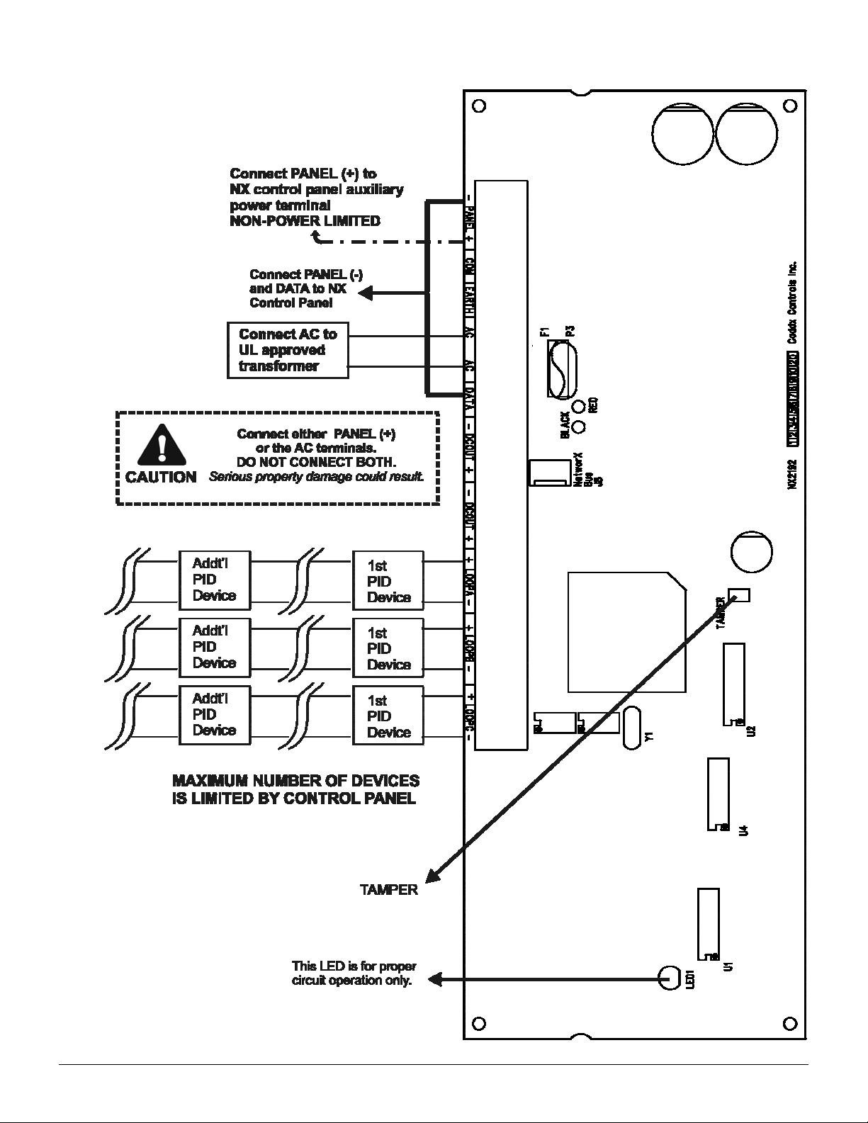
5. WIRING DIAGRAM
NX-2192E PINPOINT SYSTEM
3
Page 4
6. MAXIMUM NUMBER OF DEVICES PER WIRE RUN
The number of devices on an individual wire run must not exceed the number listed in the following table. If a star configuration is used,
the total wire length must not exceed 10000 feet per loop output.
Table 6-1
Wire
Gauge
22AWG 170 20 -- -- -18AWG 255 170 45 5 -16AWG 255 255 120 55 20
14AWG 255 255 240 135 80
1000 2500 5000 7500 10000
Length in Feet
7. ENROLLING THE PINPOINT SYSTEM
The NX-8E has the ability to automatically find and store in its memory the presence of all keypads, zone expanders, wireless receivers
and any other modules connected to the data terminal. This allows these modules to be supervised by the control panel. To enroll the
modules enter the Program Mode of the NX-8E control panel, and when the Program Mode is exited, it will automatically enroll the
devices. The enrolling process takes about 12 seconds, during which time the “Service” LED will illuminate. User codes will not be
accepted during the enrolling process. Once a module is enrolled, if it is not detected by the control, the “Service” LED will illuminate.
8. PROGRAMMING THE MODULE
To enter the program mode, press []-[8]. All of the function key LEDs will begin to flash.
Enter the "Go To Program" code (default is [9]-[7]-[1]-[3]). If the code was valid, the Service LED will flash, and the function
LEDs will illuminate steady, indicating the device to program should be entered.
Press [4] [4] [#] for the fixed address of the PinPoint module. The Armed LED will illuminate while it is waiting for a
programming location to be entered.
Enter the desired programming location. The Armed LED will begin to flash while a programming location is being entered.
Press [#]. If this is a valid location, the Armed LED will extinguish, the Ready LED will illuminate, and the binary data for the
first segment of this location will be shown on the zone LEDS.
To change the data, enter the data followed by []. The data will be entered, and the location will automatically increment to
the next segment. The data for that segment will be displayed. This procedure is repeated until the last segment is reached.
Pressing the [#] key will exit from this location. To review the data, repeat the above procedure, pressing the [] key without
entering data first. Each time the [] key is pressed the next segment is displayed.
Programming data is always one of two types of data. The first type is numerical, and can take on values from 0-255 or 0-15 depending
on the segment size. The second type is a feature selection type. Feature selection data is used to turn features on or off. LCD
Keypad Users Note: All steps required for programming are the same as the aforementioned LED keypad. The LCD keypad display will
prompt you for the data required. While in the programming mode, and not in a location, the number in parenthesis is the location you
were previously changing. For example, if the display reads "Enter location, then # (5)", it is reminding you that location 5 was the last
location you programmed. In feature selection data, the numbers of the enabled features will be displayed. However, the features not
enabled will display a hyphen (-).
IMPORTANT NOTES
To program additional points after the Program Mode is exited:
1. Re-Enter the Program Mode using the instructions in Section 8, page 4 of this manual.
2. Enter Location 0 and press [1] to initialize the “Progam Mode Designation”
3. Program the desired location(s).
9. PROGRAMMING SEQUENCE EXAMPLE
The following example assumes the installation of a single input module on the bus as address number 5, with its input mapped to zone
number 9:
Enter system program mode on the NX-2192E as previously described.
Select the configuration location for zone number 9 by entering [9] [#].
Input for segment 1 is requested. Select the device address of 5 (b inary) by e ntering [2]-[4]-[5]-[6]-[7]-[8] so that the sequence
of (1_3_____) is displayed.
Press [] [#] to exit this location.
Select the PinPoint program mode location by entering [0] [#].
Input for segment 1 is requested. Enable PinPoint program mode by entering [1] [].
Wait for the keypad to sound a ding-dong. Press [EXIT] [EXIT] to exit the system program mode.
Refer to Location 0 description for troubleshooting if the keypad does not ding-dong after PinPoint program mode is complete.
4
NX-2192E PINPOINT SYSTEM
Page 5
10. PROGRAMMING LOCATION GUIDE
LOCATION 0
Location 0 is used to communicate to the PID bus interface to enter PID Program Mode.
Segment 1 must be set to [1] to “learn” points. While in this mode, all nodes able to communicate will be enabled and mapped to pre-
programmed zones. With this in mind, prior to entering PID program mode, all zones must be either programmed with a serial number (for
devices without a dip switch) or a physical address (for devices with a dip switch). If programming is a success and no errors were
reported, a “0” will automatically be written into segment 1 of this location and the keypad will sound a ding-dong. Otherwise, the number
of errors will be written and the keypad will sound a triple beep, indicating that errors were found. If errors were found, segments 2-16 will
contain the locations of the first 15 zones with errors. Zone locations may then be examined to determine the type of error that occurred.
POINT ID PROGRAM MODE
DESIGNATION
16 segments of numerical data
NOTE: If the 8 on-board zones are enabled, then zones 1-8 are already used and may not have a PID address mapped to them.
If zone doubling is enabled, then zones 1-16 are already used and may not have a PID address mapped to them.
Segments 2-16 are “read only”.
LOCATIONS 1 – 192
Segment 1 is used to store the physical address of the corresponding node. Factory default is 255. Whether or not the device has a dip
switch, this location is programmed by the installer prior to entering PID Program Mode.
Segment 2 is used to store the input number for multiple input/output devices. Factory default is 1.
Segment 3 is used to display an error code if an error(s) occurred during the last PID program mode cycle. The following table prov ides
a description of the types of errors that may occur:
Table 10-1
PROGRAMMING NODE INFORMATION
ZONES 1 - 192
3 segments of binary data
ERROR CODE DESCRIPTION ERROR CODE DESCRIPTION
1 Node is missing. 5 Auto enroll error.
2 Multiple node responded. 6 Reserved.
3 Communication error. 7 Reserved.
4 Device type mismatch. 8 Zone programmed but node not enabled.
LOCATION 193 DEVICE OPTIONS 1 segment of feature selection data
Segment 1 selects the following options:
1 = Reserved.
2 = "On" if Loop A should be enabled; “Off” if disabled.
3 = "On" if Loop B should be enabled; “Off” if disabled.
4 = "On" if Loop C should be enabled; “Off” if disabled.
5 = “On”if 24V mode should be enabled; “Off” if 12V mode.
6 = “On” if the NX-2192E is powered from AUX + terminals of the control panel. Turning this option “On” disables NX-2192E power
monitoring.
7 = “On” if any AC Fail condition should be communicated to the central monitoring station. Option 6 overrides this condition
occurring on the NX-2192E, but not individual nodes.
8 = “On” if any Low Battery condition should be communicated to the central monitoring station. Option 6 overrides this condition
occurring on the NX-2192E, but not individual nodes.
LOCATIONS 194 - 241
Segment 1 is used to store the physical address of the corresponding node. Whether or not the device has a dip switch, this location is
programmed by the installer prior to entering PID Program Mode. This segment can also be used as an indicator that the corresponding
node had an error during the last PID Program Mode cycle, because any error causes this segment to be defaulted to address 255.
Segment 2 is used to store the output number for multiple input/output devices. Default is 1.
Segment 3 is used to display an error code if an error or errors occurred during the last PID Program Mode cycle. In the following Table
2.1, a description of the types of errors that may occur and the bit in the error code associated with the error is outlined.
NODE INFORMATION FOR
OUTPUTS 1 –48
3 segments of binary data
NX-2192E PINPOINT SYSTEM
5
Page 6
Table 10-2
AC Fail (control or exp.) does not
ERROR CODE DESCRIPTION
1 Node is missing.
2 Multiple node responded.
3 Communication error.
4 Device type mismatch.
5 Auto enroll error.
6 Reserved.
7 Output programmed to non-output device.
8 Output programmed but node not enabled.
LOCATION 242 – 336 (EVEN LOC)
Segment 1 is used to select the particular event that will trigger the output. Refer to Table 10-3 for the specific events that can be
selected.
Segment 2 is used to select the amount of time an output will remain activated when an output triggers. If this lo cation is p rogrammed as
a zero, the output will follow the particular event.
Table 10-3
# Event # Event # Event
Always On
0
1
follow AC Fail delay time
Low Battery (control or exp.)
2
Dynamic Battery Test Time
3
Listen In
4
Line Seizure
5
Telephone Line Fault
6
Program Mode
7
Over-current (control or exp.)
8
Box Tamper (control or exp.)
9
Siren Tamper (control or exp.)
10
♦ If set to follow condition, these events will be one second.
LOCATION 243 – 337 (ODD LOC)
Segment 1 selects the following special conditions:
EVENT & TIME FOR
OUTPUTS 1 - 48
Smoke Power Reset
11
Yelping Siren
12
Steady Siren
13
Any Siren
14
Steady Siren (temporal)
15
Any Siren (temporal)
16
Alarm Memory
17
Entry
18
Exit
19
Entry or Exit
20
Armed
21
SPECIAL FEATURES FOR
OUTPUTS 1 - 48
2 segments of numerical data
Disarmed
22
Ready to Arm
23
Not Ready to Arm
24
Fire
25
Fire Trouble
26
Chime
27
Beeping Keypad
28
Aux 1 Keypad Function
29♦
Aux 2 Keypad Function
30♦
Panic Keypad Function
31♦
Code Entry (set in locs 338 - 481)
32♦
2 segments of feature selection data
1 = "On" if output should time in minutes; "Off" if output times in seconds.
2 = "On" if output should latch until a code is entered; “Off” for timed.
3 = "On" if output should stop time when a code is entered.
4 = “On” for inverted output.
5 = “On” disables output during listen-in (only events 12-16).
6 = Reserved.
7 = Reserved.
8 = Reserved.
Segment 2 selects the following partitions:
1 = "On" if the event should activate when it occurs in Partition 1.
2 = "On" if the event should activate when it occurs in Partition 2.
3 = "On" if the event should activate when it occurs in Partition 3.
4 = "On" if the event should activate when it occurs in Partition 4.
5 = "On" if the event should activate when it occurs in Partition 5.
6 = "On" if the event should activate when it occurs in Partition 6.
7 = "On" if the event should activate when it occurs in Partition 7.
8 = "On" if the event should activate when it occurs in Partition 8.
6
NX-2192E PINPOINT SYSTEM
Page 7

Table 10-4
LED DESCRIPTION OUTPUTS
TABLE 10-4
IS USED TO
PROGRAM
LOCATIONS
338 - 481
1 "On" if code will activate output; "Off" if it will not.
2 "On" if code will activate output; "Off" if it will not.
3 "On" if code will activate output; "Off" if it will not.
4 "On" if code will activate output; "Off" if it will not.
5 "On" if code will activate output; "Off" if it will not.
6 "On" if code will activate output; "Off" if it will not.
7 "On" if code will activate output; "Off" if it will not.
8 "On" if code will activate output; "Off" if it will not.
1, 9, 17, 25, 33, 41
2, 10, 18, 26, 34, 42
3, 11, 19, 27, 35, 43
4, 12, 20, 28, 36, 44
5, 13, 21, 29, 37, 45
6, 14, 22, 30, 38, 46
7, 15, 23, 31, 39, 47
8, 16, 24, 32, 40, 48
LOCATIONS 338 - 361
CODES 1 – 240
OUTPUTS 1 – 8 ENABLE
10 segments of feature selection data
When activating outputs with a user code (event #32), locations 338 - 361 can be used to restrict certain codes from activating certain
outputs. Each location contains 10 segments. Location 338 / segment 1 corresponds to user 1; segment 10 corresponds to user 10; and
finally location 361 / segment 1 corresponds to user 231; Segment 10 corresponds to user 240. The LEDs correspond to outputs 1 - 8.
Refer to Table 10-4 for descriptions.
LOCATIONS 362 - 385
CODES 1 – 240
OUTPUTS 9 - 16 ENABLE
10 segments of feature selection data
When activating outputs with a user code (event #32), locations 362 - 385 can be used to restrict certain codes from activating certain
outputs. Each location contains 10 segments. Location 362 / segment 1 corresponds to user 1; segment 10 corresponds to user 10; and
finally location 385 / segment 1 corresponds to user 231; Segment 10 corresponds to user 240. The LEDs correspond to outputs 9 - 16.
Refer to Table 10-4 for descriptions.
LOCATIONS 386 - 409
CODES 1 – 240
OUTPUTS 17 - 24 ENABLE
10 segments of feature selection data
When activating outputs with a user code (event #32), locations 386 - 409 can be used to restrict certain codes from activating certain
outputs. Each location contains 10 segments. Location 386 / segment 1 corresponds to user 1; segment 10 corresponds to user 10; and
finally location 409 / segment 1 corresponds to user 231; Segment 10 corresponds to user 240. The LEDs correspond to outputs 17 -
24. Refer to Table 10-4 for descriptions.
LOCATIONS 410 - 433
CODES 1 – 240
OUTPUTS 25 - 32 ENABLE
10 segments of feature selection data
When activating outputs with a user code (event #32), locations 410 - 433 can be used to restrict certain codes from activating certain
outputs. Each location contains 10 segments. Location 410 / segment 1 corresponds to user 1; segment 10 corresponds to user 10; and
finally location 433 / segment 1 corresponds to user 231; Segment 10 corresponds to user 240. The LEDs correspond to outputs 25 -
32. Refer to Table 10-4 for descriptions.
LOCATIONS 434 - 457
CODES 1 – 240
OUTPUTS 33 - 40 ENABLE
10 segments of feature selection data
When activating outputs with a user code (event #32), locations 434 - 457 can be used to restrict certain codes from activating certain
outputs. Each location contains 10 segments. Location 434 / segment 1 corresponds to user 1; segment 10 corresponds to user 10; and
finally location 457 / segment 1 corresponds to user 231; Segment 10 corresponds to user 240. The LEDs correspond to outputs 33 -
40. Refer to Table 10-4 for descriptions.
LOCATIONS 458 - 481
CODES 1 – 240
OUTPUTS 41 - 48 ENABLE
10 segments of feature selection data
When activating outputs with a user code (event #32), locations 458 - 481 can be used to restrict certain codes from activating certain
outputs. Each location contains 10 segments. Location 458 / segment 1 corresponds to user 1; segment 10 corresponds to user 10; and
finally location 481 / segment 1 corresponds to user 231; Segment 10 corresponds to user 240. The LEDs correspond to outputs 41 -
48. Refer to Table 10-4 for descriptions.
NX-2192E PINPOINT SYSTEM
7
Page 8
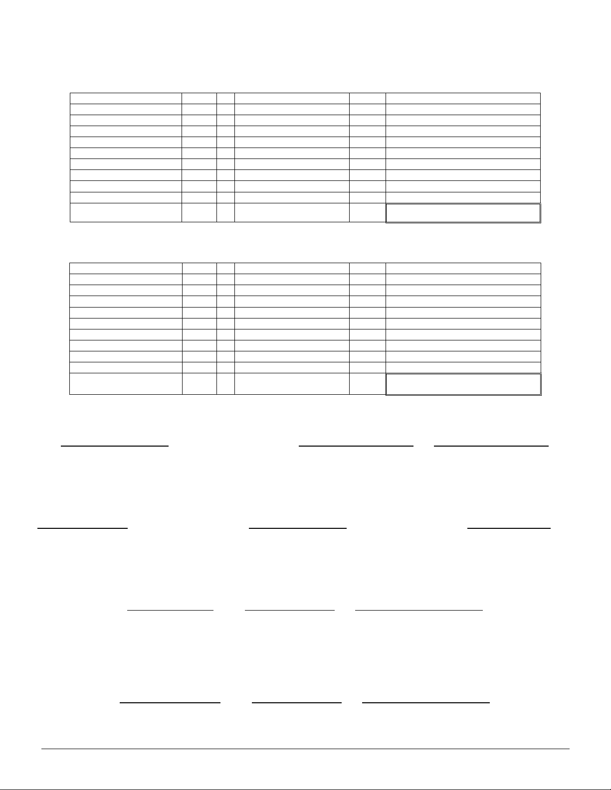
11. BATTERY CALCULATION WORKSHEET
TOTAL STANDBY CURRENT
System Component Qty Standby Current TOTAL STANDBY CURRENT
NX-8E-CF 1 X 60mA
NX-870E 1 X 20mA
NX-148E X 75mA
NX-208E Aux+
NX-216E X 30mA
NX-320E X 10mA
NX-507E X 10mA
NX-1700E X 40mA
NX-2192E X 170mA
X
13mA
TOTAL
TOTAL ALARM CURRENT
System Component Qty Device Alarm Current TOTAL ALARM CURRENT
NX-8E-CF 1 X 210mA
NX-870E 1 X 110mA
NX-148E X 110mA
NX-208E Aux+
NX-216E X 60mA
NX-320E X 10mA
NX-507E X 310mA
NX-1700E X 110mA
NX-2192E X 170mA
X
13mA
TOTAL
=
=
=
=
=
=
=
=
=
=
=
=
=
=
=
=
=
=
=
=
60mA
20mA
210mA
110mA
STANDBY AMP HOURS
mA .001 Amp/mA Hrs Ah
Total Standby Current
(Step 1)
X Conversion
Factor
ALARM HOURS
mA .001 Amp/mA Mins .0167 Hr/Min Ah
Total Alarm
Current (Step 2)
X Conversion
Factor
X Required Minutes in
MINIMUM BATTERY POWER REQUIRED
mA Ah
Standby Amp
hours (Step 3)
+
Alarm Amp Hours
TOTAL STANDBY BATTERY POWER
1.15
Minimum Battery
Power (Step 5)
8
+
NX-2192E PINPOINT SYSTEM
X Required Hours in
Standby
Standby
(Step 4)
Battery Derating
Factor
=
=
X Conversion
Factor
Minimum Battery Power
Required
=
Total Standby Battery
Power
Standby Amp Hours
Alarm Hours
=
Page 9

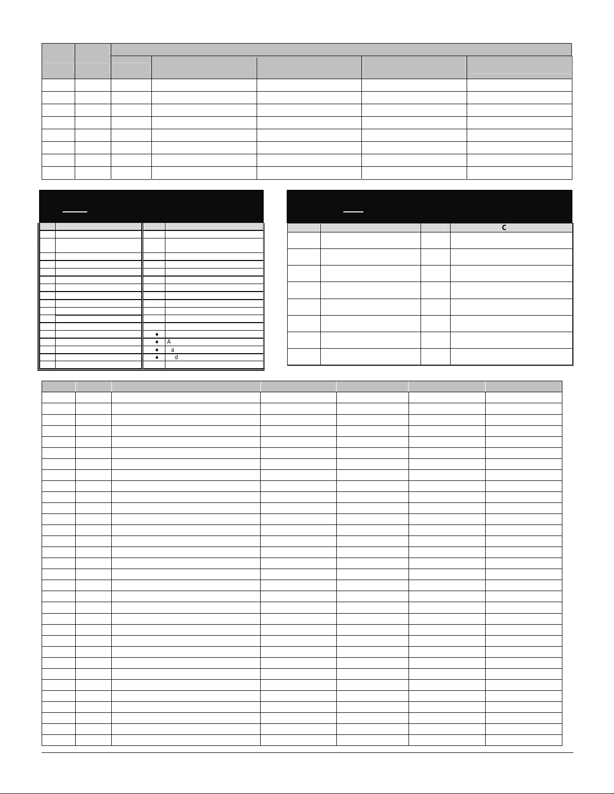
12. NX-2192E Programming Worksheets
(Defaults are printed in bold italics text.)
LOC
PAGE
0
PROGRAMMING NODE INFORMATION FOR ZONES 1 - 192
LOC PAGE
1
2
3
4
5
6
7
8
9
10
11
12
13
14
15
16
17
18
19
20
21
22
23
24
25
26
27
28
29
30
31
32
33
34
35
36
37
38
39
40
41
42
43
44
45
46
47
5
PROGRAM MODE DESIGNATION (Segement 1 must be set to [1] in order to ‘learn’ points)
Segment #1
Physical address
5
5
5
5
5
5
5
5
5
5
5
5
5
5
5
5
5
5
5
5
5
5
5
5
5
5
5
5
5
5
5
5
5
5
5
5
5
5
5
5
5
5
5
5
5
5
5
1 2 3 4 5 6 7 8 1 _ _ _ _ _ _ _ _
1 2 3 4 5 6 7 8 1 _ _ _ _ _ _ _ _
1 2 3 4 5 6 7 8 1 _ _ _ _ _ _ _ _
1 2 3 4 5 6 7 8 1 _ _ _ _ _ _ _ _
1 2 3 4 5 6 7 8 1 _ _ _ _ _ _ _ _
1 2 3 4 5 6 7 8 1 _ _ _ _ _ _ _ _
1 2 3 4 5 6 7 8 1 _ _ _ _ _ _ _ _
1 2 3 4 5 6 7 8 1 _ _ _ _ _ _ _ _
1 2 3 4 5 6 7 8 1 _ _ _ _ _ _ _ _
1 2 3 4 5 6 7 8 1 _ _ _ _ _ _ _ _
1 2 3 4 5 6 7 8 1 _ _ _ _ _ _ _ _
1 2 3 4 5 6 7 8 1 _ _ _ _ _ _ _ _
1 2 3 4 5 6 7 8 1 _ _ _ _ _ _ _ _
1 2 3 4 5 6 7 8 1 _ _ _ _ _ _ _ _
1 2 3 4 5 6 7 8 1 _ _ _ _ _ _ _ _
1 2 3 4 5 6 7 8 1 _ _ _ _ _ _ _ _
1 2 3 4 5 6 7 8 1 _ _ _ _ _ _ _ _
1 2 3 4 5 6 7 8 1 _ _ _ _ _ _ _ _
1 2 3 4 5 6 7 8 1 _ _ _ _ _ _ _ _
1 2 3 4 5 6 7 8 1 _ _ _ _ _ _ _ _
1 2 3 4 5 6 7 8 1 _ _ _ _ _ _ _ _
1 2 3 4 5 6 7 8 1 _ _ _ _ _ _ _ _
1 2 3 4 5 6 7 8 1 _ _ _ _ _ _ _ _
1 2 3 4 5 6 7 8 1 _ _ _ _ _ _ _ _
1 2 3 4 5 6 7 8 1 _ _ _ _ _ _ _ _
1 2 3 4 5 6 7 8 1 _ _ _ _ _ _ _ _
1 2 3 4 5 6 7 8 1 _ _ _ _ _ _ _ _
1 2 3 4 5 6 7 8 1 _ _ _ _ _ _ _ _
1 2 3 4 5 6 7 8 1 _ _ _ _ _ _ _ _
1 2 3 4 5 6 7 8 1 _ _ _ _ _ _ _ _
1 2 3 4 5 6 7 8 1 _ _ _ _ _ _ _ _
1 2 3 4 5 6 7 8 1 _ _ _ _ _ _ _ _
1 2 3 4 5 6 7 8 1 _ _ _ _ _ _ _ _
1 2 3 4 5 6 7 8 1 _ _ _ _ _ _ _ _
1 2 3 4 5 6 7 8 1 _ _ _ _ _ _ _ _
1 2 3 4 5 6 7 8 1 _ _ _ _ _ _ _ _
1 2 3 4 5 6 7 8 1 _ _ _ _ _ _ _ _
1 2 3 4 5 6 7 8 1 _ _ _ _ _ _ _ _
1 2 3 4 5 6 7 8 1 _ _ _ _ _ _ _ _
1 2 3 4 5 6 7 8 1 _ _ _ _ _ _ _ _
1 2 3 4 5 6 7 8 1 _ _ _ _ _ _ _ _
1 2 3 4 5 6 7 8 1 _ _ _ _ _ _ _ _
1 2 3 4 5 6 7 8 1 _ _ _ _ _ _ _ _
1 2 3 4 5 6 7 8 1 _ _ _ _ _ _ _ _
1 2 3 4 5 6 7 8 1 _ _ _ _ _ _ _ _
1 2 3 4 5 6 7 8 1 _ _ _ _ _ _ _ _
1 2 3 4 5 6 7 8 1 _ _ _ _ _ _ _ _
Segment #2
Input number
DESCRIPTION
Segment #3
Error code
Notes
NX-2192E PINPOINT SYSTEM
9
Page 10

PROGRAMMING NODE INFORMATION FOR ZONES 1 - 192
LOC PAGE
48
49
50
51
52
53
54
55
56
57
58
59
60
61
62
63
64
65
66
67
68
69
70
71
72
73
74
75
76
77
78
79
80
81
82
83
84
85
86
87
88
89
90
91
92
93
94
95
96
97
98
99
100
5
5
5
5
5
5
5
5
5
5
5
5
5
5
5
5
5
5
5
5
5
5
5
5
5
5
5
5
5
5
5
5
5
5
5
5
5
5
5
5
5
5
5
5
5
5
5
5
5
5
5
5
5
Segment #1
Physical address
1 2 3 4 5 6 7 8 1 _ _ _ _ _ _ _ _
1 2 3 4 5 6 7 8 1 _ _ _ _ _ _ _ _
1 2 3 4 5 6 7 8 1 _ _ _ _ _ _ _ _
1 2 3 4 5 6 7 8 1 _ _ _ _ _ _ _ _
1 2 3 4 5 6 7 8 1 _ _ _ _ _ _ _ _
1 2 3 4 5 6 7 8 1 _ _ _ _ _ _ _ _
1 2 3 4 5 6 7 8 1 _ _ _ _ _ _ _ _
1 2 3 4 5 6 7 8 1 _ _ _ _ _ _ _ _
1 2 3 4 5 6 7 8 1 _ _ _ _ _ _ _ _
1 2 3 4 5 6 7 8 1 _ _ _ _ _ _ _ _
1 2 3 4 5 6 7 8 1 _ _ _ _ _ _ _ _
1 2 3 4 5 6 7 8 1 _ _ _ _ _ _ _ _
1 2 3 4 5 6 7 8 1 _ _ _ _ _ _ _ _
1 2 3 4 5 6 7 8 1 _ _ _ _ _ _ _ _
1 2 3 4 5 6 7 8 1 _ _ _ _ _ _ _ _
1 2 3 4 5 6 7 8 1 _ _ _ _ _ _ _ _
1 2 3 4 5 6 7 8 1 _ _ _ _ _ _ _ _
1 2 3 4 5 6 7 8 1 _ _ _ _ _ _ _ _
1 2 3 4 5 6 7 8 1 _ _ _ _ _ _ _ _
1 2 3 4 5 6 7 8 1 _ _ _ _ _ _ _ _
1 2 3 4 5 6 7 8 1 _ _ _ _ _ _ _ _
1 2 3 4 5 6 7 8 1 _ _ _ _ _ _ _ _
1 2 3 4 5 6 7 8 1 _ _ _ _ _ _ _ _
1 2 3 4 5 6 7 8 1 _ _ _ _ _ _ _ _
1 2 3 4 5 6 7 8 1 _ _ _ _ _ _ _ _
1 2 3 4 5 6 7 8 1 _ _ _ _ _ _ _ _
1 2 3 4 5 6 7 8 1 _ _ _ _ _ _ _ _
1 2 3 4 5 6 7 8 1 _ _ _ _ _ _ _ _
1 2 3 4 5 6 7 8 1 _ _ _ _ _ _ _ _
1 2 3 4 5 6 7 8 1 _ _ _ _ _ _ _ _
1 2 3 4 5 6 7 8 1 _ _ _ _ _ _ _ _
1 2 3 4 5 6 7 8 1 _ _ _ _ _ _ _ _
1 2 3 4 5 6 7 8 1 _ _ _ _ _ _ _ _
1 2 3 4 5 6 7 8 1 _ _ _ _ _ _ _ _
1 2 3 4 5 6 7 8 1 _ _ _ _ _ _ _ _
1 2 3 4 5 6 7 8 1 _ _ _ _ _ _ _ _
1 2 3 4 5 6 7 8 1 _ _ _ _ _ _ _ _
1 2 3 4 5 6 7 8 1 _ _ _ _ _ _ _ _
1 2 3 4 5 6 7 8 1 _ _ _ _ _ _ _ _
1 2 3 4 5 6 7 8 1 _ _ _ _ _ _ _ _
1 2 3 4 5 6 7 8 1 _ _ _ _ _ _ _ _
1 2 3 4 5 6 7 8 1 _ _ _ _ _ _ _ _
1 2 3 4 5 6 7 8 1 _ _ _ _ _ _ _ _
1 2 3 4 5 6 7 8 1 _ _ _ _ _ _ _ _
1 2 3 4 5 6 7 8 1 _ _ _ _ _ _ _ _
1 2 3 4 5 6 7 8 1 _ _ _ _ _ _ _ _
1 2 3 4 5 6 7 8 1 _ _ _ _ _ _ _ _
1 2 3 4 5 6 7 8 1 _ _ _ _ _ _ _ _
1 2 3 4 5 6 7 8 1 _ _ _ _ _ _ _ _
1 2 3 4 5 6 7 8 1 _ _ _ _ _ _ _ _
1 2 3 4 5 6 7 8 1 _ _ _ _ _ _ _ _
1 2 3 4 5 6 7 8 1 _ _ _ _ _ _ _ _
1 2 3 4 5 6 7 8 1 _ _ _ _ _ _ _ _
Segment #2
Input number
Segment #3
Error code
Notes
10
NX-2192E PINPOINT SYSTEM
Page 11

PROGRAMMING NODE INFORMATION FOR ZONES 1 - 192
LOC PAGE
101
102
103
104
105
106
107
108
109
110
111
112
113
114
115
116
117
118
119
120
121
122
123
124
125
126
127
128
129
130
131
132
133
134
135
136
137
138
139
140
141
142
143
144
145
146
147
148
149
150
151
152
153
5
5
5
5
5
5
5
5
5
5
5
5
5
5
5
5
5
5
5
5
5
5
5
5
5
5
5
5
5
5
5
5
5
5
5
5
5
5
5
5
5
5
5
5
5
5
5
5
5
5
5
5
5
Segment #1
Physical address
1 2 3 4 5 6 7 8 1 _ _ _ _ _ _ _ _
1 2 3 4 5 6 7 8 1 _ _ _ _ _ _ _ _
1 2 3 4 5 6 7 8 1 _ _ _ _ _ _ _ _
1 2 3 4 5 6 7 8 1 _ _ _ _ _ _ _ _
1 2 3 4 5 6 7 8 1 _ _ _ _ _ _ _ _
1 2 3 4 5 6 7 8 1 _ _ _ _ _ _ _ _
1 2 3 4 5 6 7 8 1 _ _ _ _ _ _ _ _
1 2 3 4 5 6 7 8 1 _ _ _ _ _ _ _ _
1 2 3 4 5 6 7 8 1 _ _ _ _ _ _ _ _
1 2 3 4 5 6 7 8 1 _ _ _ _ _ _ _ _
1 2 3 4 5 6 7 8 1 _ _ _ _ _ _ _ _
1 2 3 4 5 6 7 8 1 _ _ _ _ _ _ _ _
1 2 3 4 5 6 7 8 1 _ _ _ _ _ _ _ _
1 2 3 4 5 6 7 8 1 _ _ _ _ _ _ _ _
1 2 3 4 5 6 7 8 1 _ _ _ _ _ _ _ _
1 2 3 4 5 6 7 8 1 _ _ _ _ _ _ _ _
1 2 3 4 5 6 7 8 1 _ _ _ _ _ _ _ _
1 2 3 4 5 6 7 8 1 _ _ _ _ _ _ _ _
1 2 3 4 5 6 7 8 1 _ _ _ _ _ _ _ _
1 2 3 4 5 6 7 8 1 _ _ _ _ _ _ _ _
1 2 3 4 5 6 7 8 1 _ _ _ _ _ _ _ _
1 2 3 4 5 6 7 8 1 _ _ _ _ _ _ _ _
1 2 3 4 5 6 7 8 1 _ _ _ _ _ _ _ _
1 2 3 4 5 6 7 8 1 _ _ _ _ _ _ _ _
1 2 3 4 5 6 7 8 1 _ _ _ _ _ _ _ _
1 2 3 4 5 6 7 8 1 _ _ _ _ _ _ _ _
1 2 3 4 5 6 7 8 1 _ _ _ _ _ _ _ _
1 2 3 4 5 6 7 8 1 _ _ _ _ _ _ _ _
1 2 3 4 5 6 7 8 1 _ _ _ _ _ _ _ _
1 2 3 4 5 6 7 8 1 _ _ _ _ _ _ _ _
1 2 3 4 5 6 7 8 1 _ _ _ _ _ _ _ _
1 2 3 4 5 6 7 8 1 _ _ _ _ _ _ _ _
1 2 3 4 5 6 7 8 1 _ _ _ _ _ _ _ _
1 2 3 4 5 6 7 8 1 _ _ _ _ _ _ _ _
1 2 3 4 5 6 7 8 1 _ _ _ _ _ _ _ _
1 2 3 4 5 6 7 8 1 _ _ _ _ _ _ _ _
1 2 3 4 5 6 7 8 1 _ _ _ _ _ _ _ _
1 2 3 4 5 6 7 8 1 _ _ _ _ _ _ _ _
1 2 3 4 5 6 7 8 1 _ _ _ _ _ _ _ _
1 2 3 4 5 6 7 8 1 _ _ _ _ _ _ _ _
1 2 3 4 5 6 7 8 1 _ _ _ _ _ _ _ _
1 2 3 4 5 6 7 8 1 _ _ _ _ _ _ _ _
1 2 3 4 5 6 7 8 1 _ _ _ _ _ _ _ _
1 2 3 4 5 6 7 8 1 _ _ _ _ _ _ _ _
1 2 3 4 5 6 7 8 1 _ _ _ _ _ _ _ _
1 2 3 4 5 6 7 8 1 _ _ _ _ _ _ _ _
1 2 3 4 5 6 7 8 1 _ _ _ _ _ _ _ _
1 2 3 4 5 6 7 8 1 _ _ _ _ _ _ _ _
1 2 3 4 5 6 7 8 1 _ _ _ _ _ _ _ _
1 2 3 4 5 6 7 8 1 _ _ _ _ _ _ _ _
1 2 3 4 5 6 7 8 1 _ _ _ _ _ _ _ _
1 2 3 4 5 6 7 8 1 _ _ _ _ _ _ _ _
1 2 3 4 5 6 7 8 1 _ _ _ _ _ _ _ _
Segment #2
Input number
Segment #3
Error code
Notes
NX-2192E PINPOINT SYSTEM
11
Page 12

PROGRAMMING NODE INFORMATION FOR ZONES 1 - 192
LOC PAGE
154
155
156
157
158
159
160
161
162
163
164
165
166
167
168
169
170
171
172
173
174
175
176
177
178
179
180
181
182
183
184
185
186
187
188
189
190
191
192
5
5
5
5
5
5
5
5
5
5
5
5
5
5
5
5
5
5
5
5
5
5
5
5
5
5
5
5
5
5
5
5
5
5
5
5
5
5
5
Segment #1
Physical address
1 2 3 4 5 6 7 8 1 _ _ _ _ _ _ _ _
1 2 3 4 5 6 7 8 1 _ _ _ _ _ _ _ _
1 2 3 4 5 6 7 8 1 _ _ _ _ _ _ _ _
1 2 3 4 5 6 7 8 1 _ _ _ _ _ _ _ _
1 2 3 4 5 6 7 8 1 _ _ _ _ _ _ _ _
1 2 3 4 5 6 7 8 1 _ _ _ _ _ _ _ _
1 2 3 4 5 6 7 8 1 _ _ _ _ _ _ _ _
1 2 3 4 5 6 7 8 1 _ _ _ _ _ _ _ _
1 2 3 4 5 6 7 8 1 _ _ _ _ _ _ _ _
1 2 3 4 5 6 7 8 1 _ _ _ _ _ _ _ _
1 2 3 4 5 6 7 8 1 _ _ _ _ _ _ _ _
1 2 3 4 5 6 7 8 1 _ _ _ _ _ _ _ _
1 2 3 4 5 6 7 8 1 _ _ _ _ _ _ _ _
1 2 3 4 5 6 7 8 1 _ _ _ _ _ _ _ _
1 2 3 4 5 6 7 8 1 _ _ _ _ _ _ _ _
1 2 3 4 5 6 7 8 1 _ _ _ _ _ _ _ _
1 2 3 4 5 6 7 8 1 _ _ _ _ _ _ _ _
1 2 3 4 5 6 7 8 1 _ _ _ _ _ _ _ _
1 2 3 4 5 6 7 8 1 _ _ _ _ _ _ _ _
1 2 3 4 5 6 7 8 1 _ _ _ _ _ _ _ _
1 2 3 4 5 6 7 8 1 _ _ _ _ _ _ _ _
1 2 3 4 5 6 7 8 1 _ _ _ _ _ _ _ _
1 2 3 4 5 6 7 8 1 _ _ _ _ _ _ _ _
1 2 3 4 5 6 7 8 1 _ _ _ _ _ _ _ _
1 2 3 4 5 6 7 8 1 _ _ _ _ _ _ _ _
1 2 3 4 5 6 7 8 1 _ _ _ _ _ _ _ _
1 2 3 4 5 6 7 8 1 _ _ _ _ _ _ _ _
1 2 3 4 5 6 7 8 1 _ _ _ _ _ _ _ _
1 2 3 4 5 6 7 8 1 _ _ _ _ _ _ _ _
1 2 3 4 5 6 7 8 1 _ _ _ _ _ _ _ _
1 2 3 4 5 6 7 8 1 _ _ _ _ _ _ _ _
1 2 3 4 5 6 7 8 1 _ _ _ _ _ _ _ _
1 2 3 4 5 6 7 8 1 _ _ _ _ _ _ _ _
1 2 3 4 5 6 7 8 1 _ _ _ _ _ _ _ _
1 2 3 4 5 6 7 8 1 _ _ _ _ _ _ _ _
1 2 3 4 5 6 7 8 1 _ _ _ _ _ _ _ _
1 2 3 4 5 6 7 8 1 _ _ _ _ _ _ _ _
1 2 3 4 5 6 7 8 1 _ _ _ _ _ _ _ _
1 2 3 4 5 6 7 8 1 _ _ _ _ _ _ _ _
Segment #2
Input number
Segment #3
Error code
Notes
12
NX-2192E PINPOINT SYSTEM
Page 13

LOC PAGE DESCRIPTION
2192E is powered from AUX + terminals of the control panel. Turning this option “On” disable s
tral monitoring station. Option 6 overrides
“On” if any Low Battery condition should be communicated to the central monitoring station. Option 6
5
DEVICE OPTIONS 193
1 = Reserved.
2 = "On" if Loop A should be enabled; “Off” if disabled.
3 = "On" if Loop B should be enabled; “Off” if disabled.
4 = "On" if Loop C should be enabled; “Off” if disabled.
5 = “On” if 24V mode; “Off” if 12V mode.
6 = “On” if the NX-
NX-2192E power monitoring.
7 = “On” if any AC Fail condition should be communicated to the cen
this condition occurring on the NX-2192E, but not individual nodes.
8 =
overrides this condition occurring on the NX-2192E, but not individual nodes.
LOC PAGE OUTPUT
194
195
196
197
198
199
200
201
202
203
204
205
206
207
208
209
210
211
212
213
214
215
216
217
218
219
220
221
222
223
224
225
226
227
228
229
230
231
232
233
5
5
5
5
5
5
5
5
5
5
5
5
5
5
5
5
5
5
5
5
5
5
5
5
5
5
5
5
5
5
5
5
5
5
5
5
5
5
5
5
1
2
3
4
5
6
7
8
9
10
11
12
13
14
15
16
17
18
19
20
21
22
23
24
25
26
27
28
29
30
31
32
33
34
35
36
37
38
39
40
Segment #1
Physical address
1 2 3 4 5 6 7 8 1 _ _ _ _ _ _ _ _
1 2 3 4 5 6 7 8 1 _ _ _ _ _ _ _ _
1 2 3 4 5 6 7 8 1 _ _ _ _ _ _ _ _
1 2 3 4 5 6 7 8 1 _ _ _ _ _ _ _ _
1 2 3 4 5 6 7 8 1 _ _ _ _ _ _ _ _
1 2 3 4 5 6 7 8 1 _ _ _ _ _ _ _ _
1 2 3 4 5 6 7 8 1 _ _ _ _ _ _ _ _
1 2 3 4 5 6 7 8 1 _ _ _ _ _ _ _ _
1 2 3 4 5 6 7 8 1 _ _ _ _ _ _ _ _
1 2 3 4 5 6 7 8 1 _ _ _ _ _ _ _ _
1 2 3 4 5 6 7 8 1 _ _ _ _ _ _ _ _
1 2 3 4 5 6 7 8 1 _ _ _ _ _ _ _ _
1 2 3 4 5 6 7 8 1 _ _ _ _ _ _ _ _
1 2 3 4 5 6 7 8 1 _ _ _ _ _ _ _ _
1 2 3 4 5 6 7 8 1 _ _ _ _ _ _ _ _
1 2 3 4 5 6 7 8 1 _ _ _ _ _ _ _ _
1 2 3 4 5 6 7 8 1 _ _ _ _ _ _ _ _
1 2 3 4 5 6 7 8 1 _ _ _ _ _ _ _ _
1 2 3 4 5 6 7 8 1 _ _ _ _ _ _ _ _
1 2 3 4 5 6 7 8 1 _ _ _ _ _ _ _ _
1 2 3 4 5 6 7 8 1 _ _ _ _ _ _ _ _
1 2 3 4 5 6 7 8 1 _ _ _ _ _ _ _ _
1 2 3 4 5 6 7 8 1 _ _ _ _ _ _ _ _
1 2 3 4 5 6 7 8 1 _ _ _ _ _ _ _ _
1 2 3 4 5 6 7 8 1 _ _ _ _ _ _ _ _
1 2 3 4 5 6 7 8 1 _ _ _ _ _ _ _ _
1 2 3 4 5 6 7 8 1 _ _ _ _ _ _ _ _
1 2 3 4 5 6 7 8 1 _ _ _ _ _ _ _ _
1 2 3 4 5 6 7 8 1 _ _ _ _ _ _ _ _
1 2 3 4 5 6 7 8 1 _ _ _ _ _ _ _ _
1 2 3 4 5 6 7 8 1 _ _ _ _ _ _ _ _
1 2 3 4 5 6 7 8 1 _ _ _ _ _ _ _ _
1 2 3 4 5 6 7 8 1 _ _ _ _ _ _ _ _
1 2 3 4 5 6 7 8 1 _ _ _ _ _ _ _ _
1 2 3 4 5 6 7 8 1 _ _ _ _ _ _ _ _
1 2 3 4 5 6 7 8 1 _ _ _ _ _ _ _ _
1 2 3 4 5 6 7 8 1 _ _ _ _ _ _ _ _
1 2 3 4 5 6 7 8 1 _ _ _ _ _ _ _ _
1 2 3 4 5 6 7 8 1 _ _ _ _ _ _ _ _
1 2 3 4 5 6 7 8 1 _ _ _ _ _ _ _ _
PROGRAMMING NODE INFORMATION FOR OUTPUTS 1 - 48
Segment #2
Output number
Segment #3
Error code
Notes
NX-2192E PINPOINT SYSTEM
13
Page 14
LOC PAGE OUTPUT
234
235
236
237
238
239
240
241
5
5
5
5
5
5
5
5
41
42
43
44
45
46
47
48
Segment #1
Physical address
1 2 3 4 5 6 7 8 1 _ _ _ _ _ _ _ _
1 2 3 4 5 6 7 8 1 _ _ _ _ _ _ _ _
1 2 3 4 5 6 7 8 1 _ _ _ _ _ _ _ _
1 2 3 4 5 6 7 8 1 _ _ _ _ _ _ _ _
1 2 3 4 5 6 7 8 1 _ _ _ _ _ _ _ _
1 2 3 4 5 6 7 8 1 _ _ _ _ _ _ _ _
1 2 3 4 5 6 7 8 1 _ _ _ _ _ _ _ _
1 2 3 4 5 6 7 8 1 _ _ _ _ _ _ _ _
PROGRAMMING NODE INFORMATION FOR OUTPUTS 1 - 48
Segment #2
Output number
Segment #3
Error code
Notes
USE THE FOLLOWING TABLE FOR
EVEN NUMBERED LOCATIONS 242 – 336
# Event # Event
0 Always On 17 Alarm Memory
AC Fail (control or exp.) does
1
not follow AC Fail delay time
2 Low Battery (control or exp.) 19 Exit
3 Dynamic Battery Test Time 20 Entry or Exit
4 Listen In 21 Armed
5 Line Seizure 22 Disarmed
6 Telephone Line Fault 23 Ready to Arm
7 Program Mode 24 Not Ready to Arm
8 Over-current (control or exp.) 25 Fire
9 Box Tamper (control or exp.) 26 Fire Trouble
10 Siren Tamper (control or exp.) 27 Chime
11 Smoke Power Reset 28 Beeping Keypad
12 Yelping Siren 29♦ Aux 1 Keypad Function
13 Steady Siren 30♦ Aux 2 Keypad Function
14 Any Siren 31♦ Panic Keypad Function
15 Steady Siren (temporal) 32♦ Code Entry ( locs 338 - 481)
16 Any Siren (temporal)
(EVENT / TIME)
18 Entry
SEG 1 DESCRIPTION SEG 2 DESCRIPTION
1 = ON times in minutes
2 = ON to latch until a code is
3 = ON if output should stop time
4 = ON for inverted output 4 = On if event activates output in
5 = ON disables output during
6 = Reserved 6 =
7 = Reserved 7 =
8 = Reserved 8 =
USE THE FOLLOWING TABLE FOR
ODD NUMBERED LOCATIONS 243 – 337
(SPECIAL FEATURES)
OFF if times in seconds
entered; OFF for timed
when a code is entered
listen-in (only events 12-16)
1 = On if event activates output in
Partition 1
2 = On if event activates output in
Partition 2
3 = On if event activates output in
Partition 3
Partition 4
5 = On if event activates output in
Partition 5
On if event activates output in
Partition 6
On if event activates output in
Partition 7
On if event activates output in
Partition 8
LOC PAGE DESCRIPTION SEG 1 DEFAULT SEG 1 DATA SEG 2 DEFAULT SEG 2 DATA
242
243
244
245
246
247
248
249
250
251
252
253
254
255
256
257
258
259
260
261
262
263
264
265
266
267
268
269
270
271
272
273
6 EVENT / TIME – OUTPUT 1
6 FEATURES – OUTPUT 1
6 EVENT / TIME – OUTPUT 2
6 FEATURES – OUTPUT 2
6 EVENT / TIME – OUTPUT 3
6 FEATURES – OUTPUT 3
6 EVENT / TIME – OUTPUT 4
6 FEATURES – OUTPUT 4
6 EVENT / TIME – OUTPUT 5
6 FEATURES – OUTPUT 5
6 EVENT / TIME – OUTPUT 6
6 FEATURES – OUTPUT 6
6 EVENT / TIME – OUTPUT 7
6 FEATURES – OUTPUT 7
6 EVENT / TIME – OUTPUT 8
6 FEATURES – OUTPUT 8
6 EVENT / TIME – OUTPUT 9
6 FEATURES – OUTPUT 9
6 EVENT / TIME – OUTPUT 10
6 FEATURES – OUTPUT 10
6 EVENT / TIME – OUTPUT 11
6 FEATURES – OUTPUT 11
6 EVENT / TIME – OUTPUT 12
6 FEATURES – OUTPUT 12
6 EVENT / TIME – OUTPUT 13
6 FEATURES – OUTPUT 13
6 EVENT / TIME – OUTPUT 14
6 FEATURES – OUTPUT 14
6 EVENT / TIME – OUTPUT 15
6 FEATURES – OUTPUT 15
6 EVENT / TIME – OUTPUT 16
6 FEATURES – OUTPUT 16
14=Any Siren
_ _ _ _ _ _ _ _
14=Any Siren
_ _ _ _ _ _ _ _
14=Any Siren
_ _ _ _ _ _ _ _
14=Any Siren
_ _ _ _ _ _ _ _
14=Any Siren
_ _ _ _ _ _ _ _
14=Any Siren
_ _ _ _ _ _ _ _
14=Any Siren
_ _ _ _ _ _ _ _
14=Any Siren
_ _ _ _ _ _ _ _
14=Any Siren
_ _ _ _ _ _ _ _
14=Any Siren
_ _ _ _ _ _ _ _
14=Any Siren
_ _ _ _ _ _ _ _
14=Any Siren
_ _ _ _ _ _ _ _
14=Any Siren
_ _ _ _ _ _ _ _
14=Any Siren
_ _ _ _ _ _ _ _
14=Any Siren
_ _ _ _ _ _ _ _
14=Any Siren
_ _ _ _ _ _ _ _
0=Follow Evt
1 2 3 4 5 6 7 8
0=Follow Evt
1 2 3 4 5 6 7 8
0=Follow Evt
1 2 3 4 5 6 7 8
0=Follow Evt
1 2 3 4 5 6 7 8
0=Follow Evt
1 2 3 4 5 6 7 8
0=Follow Evt
1 2 3 4 5 6 7 8
0=Follow Evt
1 2 3 4 5 6 7 8
0=Follow Evt
1 2 3 4 5 6 7 8
0=Follow Evt
1 2 3 4 5 6 7 8
0=Follow Evt
1 2 3 4 5 6 7 8
0=Follow Evt
1 2 3 4 5 6 7 8
0=Follow Evt
1 2 3 4 5 6 7 8
0=Follow Evt
1 2 3 4 5 6 7 8
0=Follow Evt
1 2 3 4 5 6 7 8
0=Follow Evt
1 2 3 4 5 6 7 8
0=Follow Evt
1 2 3 4 5 6 7 8
14
NX-2192E PINPOINT SYSTEM
Page 15

LOC PAGE DESCRIPTION SEG 1 DEFAULT SEG 1 DATA SEG 2 DEFAULT SEG 2 DATA
274
275
276
277
278
279
280
281
282
283
284
285
286
287
288
289
290
291
292
293
294
295
296
297
298
299
300
301
302
303
304
305
306
307
308
309
310
311
312
313
314
315
316
317
318
319
320
321
322
323
324
325
326
327
328
329
330
331
332
333
334
335
6 EVENT / TIME – OUTPUT 17
6 FEATURES – OUTPUT 17
6 EVENT / TIME – OUTPUT 18
6 FEATURES – OUTPUT 18
6 EVENT / TIME – OUTPUT 19
6 FEATURES – OUTPUT 19
6 EVENT / TIME – OUTPUT 20
6 FEATURES – OUTPUT 20
6 EVENT / TIME – OUTPUT 21
6 FEATURES – OUTPUT 21
6 EVENT / TIME – OUTPUT 22
6 FEATURES – OUTPUT 22
6 EVENT /TIME – OUTPUT 23
6 FEATURES – OUTPUT 23
6 EVENT / TIME – OUTPUT 24
6 FEATURES – OUTPUT 24
6 EVENT / TIME – OUTPUT 25
6 FEATURES – OUTPUT 25
6 EVENT / TIME – OUTPUT 26
6 FEATURES – OUTPUT 26
6 EVENT / TIME – OUTPUT 27
6 FEATURES – OUTPUT 27
6 EVENT / TIME – OUTPUT 28
6 FEATURES – OUTPUT 28
6 EVENT / TIME – OUTPUT 29
6 FEATURES – OUTPUT 29
6 EVENT / TIME – OUTPUT 30
6 FEATURES – OUTPUT 30
6 EVENT / TIME – OUTPUT 31
6 FEATURES – OUTPUT 31
6 EVENT / TIME – OUTPUT 32
6 FEATURES – OUTPUT 32
6 EVENT / TIME – OUTPUT 33
6 FEATURES – OUTPUT 33
6 EVENT / TIME – OUTPUT 34
6 FEATURES – OUTPUT 34
6 EVENT / TIME – OUTPUT 35
6 FEATURES – OUTPUT 35
6 EVENT / TIME – OUTPUT 36
6 FEATURES – OUTPUT 36
6 EVENT / TIME – OUTPUT 37
6 FEATURES – OUTPUT 37
6 EVENT / TIME – OUTPUT 38
6 FEATURES – OUTPUT 38
6 EVENT / TIME – OUTPUT 39
6 FEATURES – OUTPUT 39
6 EVENT / TIME – OUTPUT 40
6 FEATURES – OUTPUT 40
6 EVENT / TIME – OUTPUT 41
6 FEATURES – OUTPUT 41
6 EVENT / TIME – OUTPUT 42
6 FEATURES – OUTPUT 42
6 EVENT / TIME – OUTPUT 43
6 FEATURES – OUTPUT 43
6 EVENT / TIME – OUTPUT 44
6 FEATURES – OUTPUT 44
6 EVENT / TIME – OUTPUT 45
6 FEATURES – OUTPUT 45
6 EVENT / TIME – OUTPUT 46
6 FEATURES – OUTPUT 46
6 EVENT / TIME – OUTPUT 47
6 FEATURES – OUTPUT 47
14=Any Siren
_ _ _ _ _ _ _ _
14=Any Siren
_ _ _ _ _ _ _ _
14=Any Siren
_ _ _ _ _ _ _ _
14=Any Siren
_ _ _ _ _ _ _ _
14=Any Siren
_ _ _ _ _ _ _ _
14=Any Siren
_ _ _ _ _ _ _ _
14=Any Siren
_ _ _ _ _ _ _ _
14=Any Siren
_ _ _ _ _ _ _ _
14=Any Siren
_ _ _ _ _ _ _ _
14=Any Siren
_ _ _ _ _ _ _ _
14=Any Siren
_ _ _ _ _ _ _ _
14=Any Siren
_ _ _ _ _ _ _ _
14=Any Siren
_ _ _ _ _ _ _ _
14=Any Siren
_ _ _ _ _ _ _ _
14=Any Siren
_ _ _ _ _ _ _ _
14=Any Siren
_ _ _ _ _ _ _ _
14=Any Siren
_ _ _ _ _ _ _ _
14=Any Siren
_ _ _ _ _ _ _ _
14=Any Siren
_ _ _ _ _ _ _ _
14=Any Siren
_ _ _ _ _ _ _ _
14=Any Siren
_ _ _ _ _ _ _ _
14=Any Siren
_ _ _ _ _ _ _ _
14=Any Siren
_ _ _ _ _ _ _ _
14=Any Siren
_ _ _ _ _ _ _ _
14=Any Siren
_ _ _ _ _ _ _ _
14=Any Siren
_ _ _ _ _ _ _ _
14=Any Siren
_ _ _ _ _ _ _ _
14=Any Siren
_ _ _ _ _ _ _ _
14=Any Siren
_ _ _ _ _ _ _ _
14=Any Siren
_ _ _ _ _ _ _ _
14=Any Siren
_ _ _ _ _ _ _ _
0=Follow Evt
1 2 3 4 5 6 7 8
0=Follow Evt
1 2 3 4 5 6 7 8
0=Follow Evt
1 2 3 4 5 6 7 8
0=Follow Evt
1 2 3 4 5 6 7 8
0=Follow Evt
1 2 3 4 5 6 7 8
0=Follow Evt
1 2 3 4 5 6 7 8
0=Follow Evt
1 2 3 4 5 6 7 8
0=Follow Evt
1 2 3 4 5 6 7 8
0=Follow Evt
1 2 3 4 5 6 7 8
0=Follow Evt
1 2 3 4 5 6 7 8
0=Follow Evt
1 2 3 4 5 6 7 8
0=Follow Evt
1 2 3 4 5 6 7 8
0=Follow Evt
1 2 3 4 5 6 7 8
0=Follow Evt
1 2 3 4 5 6 7 8
0=Follow Evt
1 2 3 4 5 6 7 8
0=Follow Evt
1 2 3 4 5 6 7 8
0=Follow Evt
1 2 3 4 5 6 7 8
0=Follow Evt
1 2 3 4 5 6 7 8
0=Follow Evt
1 2 3 4 5 6 7 8
0=Follow Evt
1 2 3 4 5 6 7 8
0=Follow Evt
1 2 3 4 5 6 7 8
0=Follow Evt
1 2 3 4 5 6 7 8
0=Follow Evt
1 2 3 4 5 6 7 8
0=Follow Evt
1 2 3 4 5 6 7 8
0=Follow Evt
1 2 3 4 5 6 7 8
0=Follow Evt
1 2 3 4 5 6 7 8
0=Follow Evt
1 2 3 4 5 6 7 8
0=Follow Evt
1 2 3 4 5 6 7 8
0=Follow Evt
1 2 3 4 5 6 7 8
0=Follow Evt
1 2 3 4 5 6 7 8
0=Follow Evt
1 2 3 4 5 6 7 8
NX-2192E PINPOINT SYSTEM
15
Page 16

LOC PAGE DESCRIPTION SEG 1 DEFAULT SEG 1 DATA SEG 2 DEFAULT SEG 2 DATA
336
337
6 EVENT / TIME – OUTPUT 48
6 FEATURES – OUTPUT 48
14=Any Siren
_ _ _ _ _ _ _ _
0=Follow Evt
1 2 3 4 5 6 7 8
LOC PAGE DESCRIPTION
CODES 1-10 OUTPUT SELECTION (Circle the numbers to disable)
338
339
340
341
342
343
7
User 1 2 3 4 5 6 7 8 9 10
Output 1
Output 2
Output 3
Output 4
Output 5
Output 6
Output 7
Output 8
CODES 11-20 OUTPUT SELECTION (Circle the numbers to disable)
7
User 11 12 13 14 15 16 17 18 19 20
Output 1
Output 2
Output 3
Output 4
Output 5
Output 6
Output 7
Output 8
CODES 21-30 OUTPUT SELECTION (Circle the numbers to disable)
7
User 21 22 23 24 25 26 27 28 29 30
Output 1
Output 2
Output 3
Output 4
Output 5
Output 6
Output 7
Output 8
CODES 31-40 OUTPUT SELECTION (Circle the numbers to program)
7
User 31 32 33 34 35 36 37 38 39 40
Output 1
Output 2
Output 3
Output 4
Output 5
Output 6
Output 7
Output 8
CODES 41-50 OUTPUT SELECTION (Circle the numbers to disable)
7
User 41 42 43 44 45 46 47 48 49 50
Output 1
Output 2
Output 3
Output 4
Output 5
Output 6
Output 7
Output 8
CODES 51-60 OUTPUT SELECTION (Circle the numbers to disable)
7
User 51 52 53 54 55 56 57 58 59 60
Output 1
Output 2
Output 3
Output 4
Output 5
Output 6
Output 7
Output 8
1
2
3
4
5
6
7
8
1
2
3
4
5
6
7
8
1
2
3
4
5
6
7
8
1
2
3
4
5
6
7
8
1
2
3
4
5
6
7
8
1
2
3
4
5
6
7
8
1
2
3
4
5
6
7
8
1
2
3
4
5
6
7
8
1
2
3
4
5
6
7
8
1
2
3
4
5
6
7
8
1
2
3
4
5
6
7
8
1
2
3
4
5
6
7
8
1
2
3
4
5
6
7
8
1
2
3
4
5
6
7
8
1
2
3
4
5
6
7
8
1
2
3
4
5
6
7
8
1
2
3
4
5
6
7
8
1
2
3
4
5
6
7
8
1
2
3
4
5
6
7
8
1
2
3
4
5
6
7
8
1
2
3
4
5
6
7
8
1
2
3
4
5
6
7
8
1
2
3
4
5
6
7
8
1
2
3
4
5
6
7
8
1
2
3
4
5
6
7
8
1
2
3
4
5
6
7
8
1
2
3
4
5
6
7
8
1
2
3
4
5
6
7
8
1
2
3
4
5
6
7
8
1
2
3
4
5
6
7
8
1
2
3
4
5
6
7
8
1
2
3
4
5
6
7
8
1
2
3
4
5
6
7
8
1
2
3
4
5
6
7
8
1
2
3
4
5
6
7
8
1
2
3
4
5
6
7
8
1
2
3
4
5
6
7
8
1
2
3
4
5
6
7
8
1
2
3
4
5
6
7
8
1
2
3
4
5
6
7
8
1
2
3
4
5
6
7
8
1
2
3
4
5
6
7
8
1
2
3
4
5
6
7
8
1
2
3
4
5
6
7
8
1
2
3
4
5
6
7
8
1
2
3
4
5
6
7
8
1
2
3
4
5
6
7
8
1
2
3
4
5
6
7
8
1
2
3
4
5
6
7
8
1
2
3
4
5
6
7
8
1
2
3
4
5
6
7
8
1
2
3
4
5
6
7
8
1
2
3
4
5
6
7
8
1
2
3
4
5
6
7
8
1
2
3
4
5
6
7
8
1
2
3
4
5
6
7
8
1
2
3
4
5
6
7
8
1
2
3
4
5
6
7
8
1
2
3
4
5
6
7
8
1
2
3
4
5
6
7
8
16
NX-2192E PINPOINT SYSTEM
Page 17

LOC PAGE DESCRIPTION
CODES 61-70 OUTPUT SELECTION (Circle the numbers to disable)
344
7
User 61 62 63 64 65 66 67 68 69 70
345
Output 1
Output 2
Output 3
Output 4
Output 5
Output 6
Output 7
Output 8
CODES 71-80 OUTPUT SELECTION (Circle the numbers to disable)
7
1
2
3
4
5
6
7
8
1
2
3
4
5
6
7
8
1
2
3
4
5
6
7
8
1
2
3
4
5
6
7
8
1
2
3
4
5
6
7
8
1
2
3
4
5
6
7
8
1
2
3
4
5
6
7
8
1
2
3
4
5
6
7
8
1
2
3
4
5
6
7
8
1
2
3
4
5
6
7
8
User 71 72 73 74 75 76 77 78 79 80
346
Output 1
Output 2
Output 3
Output 4
Output 5
Output 6
Output 7
Output 8
CODES 81-90 OUTPUT SELECTION (Circle the numbers to disable)
1
2
3
4
5
6
7
8
1
2
3
4
5
6
7
8
1
2
3
4
5
6
7
8
1
2
3
4
5
6
7
8
1
2
3
4
5
6
7
8
1
2
3
4
5
6
7
8
1
2
3
4
5
6
7
8
1
2
3
4
5
6
7
8
1
2
3
4
5
6
7
8
1
2
3
4
5
6
7
8
User 81 82 83 84 85 86 87 88 89 90
347
Output 1
Output 2
Output 3
Output 4
Output 5
Output 6
Output 7
Output 8
CODES 91-100 OUTPUT SELECTION (Circle the numbers to disable)
7
1
2
3
4
5
6
7
8
1
2
3
4
5
6
7
8
1
2
3
4
5
6
7
8
1
2
3
4
5
6
7
8
1
2
3
4
5
6
7
8
1
2
3
4
5
6
7
8
1
2
3
4
5
6
7
8
1
2
3
4
5
6
7
8
1
2
3
4
5
6
7
8
1
2
3
4
5
6
7
8
User 91 92 93 94 95 96 97 98 99 100
348
Output 1
Output 2
Output 3
Output 4
Output 5
Output 6
Output 7
Output 8
CODES 101-110 OUTPUT SELECTION (Circle the numbers to disable)
7
1
2
3
4
5
6
7
8
1
2
3
4
5
6
7
8
1
2
3
4
5
6
7
8
1
2
3
4
5
6
7
8
1
2
3
4
5
6
7
8
1
2
3
4
5
6
7
8
1
2
3
4
5
6
7
8
1
2
3
4
5
6
7
8
1
2
3
4
5
6
7
8
1
2
3
4
5
6
7
8
User 101 102 103 104 105 106 107 108 109 110
349
Output 1
Output 2
Output 3
Output 4
Output 5
Output 6
Output 7
Output 8
CODES 111-120 OUTPUT SELECTION (Circle the numbers to disable)
7
1
2
3
4
5
6
7
8
1
2
3
4
5
6
7
8
1
2
3
4
5
6
7
8
1
2
3
4
5
6
7
8
1
2
3
4
5
6
7
8
1
2
3
4
5
6
7
8
1
2
3
4
5
6
7
8
1
2
3
4
5
6
7
8
1
2
3
4
5
6
7
8
1
2
3
4
5
6
7
8
User 111 112 113 114 115 116 117 118 119 120
Output 1
Output 2
Output 3
Output 4
Output 5
Output 6
Output 7
Output 8
1
2
3
4
5
6
7
8
1
2
3
4
5
6
7
8
1
2
3
4
5
6
7
8
1
2
3
4
5
6
7
8
1
2
3
4
5
6
7
8
1
2
3
4
5
6
7
8
1
2
3
4
5
6
7
8
1
2
3
4
5
6
7
8
1
2
3
4
5
6
7
8
1
2
3
4
5
6
7
8
NX-2192E PINPOINT SYSTEM
17
Page 18

LOC PAGE DESCRIPTION
CODES 121-130 OUTPUT SELECTION (Circle the numbers to disable)
350
7
User 121 122 123 124 125 126 127 128 129 130
351
Output 1
Output 2
Output 3
Output 4
Output 5
Output 6
Output 7
Output 8
CODES 131-140 OUTPUT SELECTION (Circle the numbers to disable)
7
1
2
3
4
5
6
7
8
1
2
3
4
5
6
7
8
1
2
3
4
5
6
7
8
1
2
3
4
5
6
7
8
1
2
3
4
5
6
7
8
1
2
3
4
5
6
7
8
1
2
3
4
5
6
7
8
1
2
3
4
5
6
7
8
1
2
3
4
5
6
7
8
1
2
3
4
5
6
7
8
User 131 132 133 134 135 136 137 138 139 140
352
Output 1
Output 2
Output 3
Output 4
Output 5
Output 6
Output 7
Output 8
CODES 141-150 OUTPUT SELECTION (Circle the numbers to disable)
7
1
2
3
4
5
6
7
8
1
2
3
4
5
6
7
8
1
2
3
4
5
6
7
8
1
2
3
4
5
6
7
8
1
2
3
4
5
6
7
8
1
2
3
4
5
6
7
8
1
2
3
4
5
6
7
8
1
2
3
4
5
6
7
8
1
2
3
4
5
6
7
8
1
2
3
4
5
6
7
8
User 141 142 143 144 145 146 147 148 149 150
353
Output 1
Output 2
Output 3
Output 4
Output 5
Output 6
Output 7
Output 8
CODES 151-160 OUTPUT SELECTION (Circle the numbers to disable)
7
1
2
3
4
5
6
7
8
1
2
3
4
5
6
7
8
1
2
3
4
5
6
7
8
1
2
3
4
5
6
7
8
1
2
3
4
5
6
7
8
1
2
3
4
5
6
7
8
1
2
3
4
5
6
7
8
1
2
3
4
5
6
7
8
1
2
3
4
5
6
7
8
1
2
3
4
5
6
7
8
User 151 152 153 154 155 156 157 158 159 160
354
Output 1
Output 2
Output 3
Output 4
Output 5
Output 6
Output 7
Output 8
CODES 161-170 OUTPUT SELECTION (Circle the numbers to disable)
7
1
2
3
4
5
6
7
8
1
2
3
4
5
6
7
8
1
2
3
4
5
6
7
8
1
2
3
4
5
6
7
8
1
2
3
4
5
6
7
8
1
2
3
4
5
6
7
8
1
2
3
4
5
6
7
8
1
2
3
4
5
6
7
8
1
2
3
4
5
6
7
8
1
2
3
4
5
6
7
8
User 161 162 163 164 165 166 167 168 169 170
355
Output 1
Output 2
Output 3
Output 4
Output 5
Output 6
Output 7
Output 8
CODES 171-180 OUTPUT SELECTION (Circle the numbers to disable)
7
1
2
3
4
5
6
7
8
1
2
3
4
5
6
7
8
1
2
3
4
5
6
7
8
1
2
3
4
5
6
7
8
1
2
3
4
5
6
7
8
1
2
3
4
5
6
7
8
1
2
3
4
5
6
7
8
1
2
3
4
5
6
7
8
1
2
3
4
5
6
7
8
1
2
3
4
5
6
7
8
User 171 172 173 174 175 176 177 178 179 180
Output 1
Output 2
Output 3
Output 4
Output 5
Output 6
Output 7
Output 8
1
2
3
4
5
6
7
8
1
2
3
4
5
6
7
8
1
2
3
4
5
6
7
8
1
2
3
4
5
6
7
8
1
2
3
4
5
6
7
8
1
2
3
4
5
6
7
8
1
2
3
4
5
6
7
8
1
2
3
4
5
6
7
8
1
2
3
4
5
6
7
8
1
2
3
4
5
6
7
8
18
NX-2192E PINPOINT SYSTEM
Page 19

LOC PAGE DESCRIPTION
CODES 181-190 OUTPUT SELECTION (Circle the numbers to disable)
356
7
User 181 182 183 184 185 186 187 188 189 190
357
Output 1
Output 2
Output 3
Output 4
Output 5
Output 6
Output 7
Output 8
CODES 191-200 OUTPUT SELECTION (Circle the numbers to disable)
7
1
2
3
4
5
6
7
8
1
2
3
4
5
6
7
8
1
2
3
4
5
6
7
8
1
2
3
4
5
6
7
8
1
2
3
4
5
6
7
8
1
2
3
4
5
6
7
8
1
2
3
4
5
6
7
8
1
2
3
4
5
6
7
8
1
2
3
4
5
6
7
8
1
2
3
4
5
6
7
8
User 191 192 193 194 195 196 197 198 199 200
358
Output 1
Output 2
Output 3
Output 4
Output 5
Output 6
Output 7
Output 8
CODES 201-210 OUTPUT SELECTION (Circle the numbers to disable)
7
1
2
3
4
5
6
7
8
1
2
3
4
5
6
7
8
1
2
3
4
5
6
7
8
1
2
3
4
5
6
7
8
1
2
3
4
5
6
7
8
1
2
3
4
5
6
7
8
1
2
3
4
5
6
7
8
1
2
3
4
5
6
7
8
1
2
3
4
5
6
7
8
1
2
3
4
5
6
7
8
User 201 202 203 204 205 206 207 208 209 210
359
Output 1
Output 2
Output 3
Output 4
Output 5
Output 6
Output 7
Output 8
CODES 211-220 OUTPUT SELECTION (Circle the numbers to disable)
7
1
2
3
4
5
6
7
8
1
2
3
4
5
6
7
8
1
2
3
4
5
6
7
8
1
2
3
4
5
6
7
8
1
2
3
4
5
6
7
8
1
2
3
4
5
6
7
8
1
2
3
4
5
6
7
8
1
2
3
4
5
6
7
8
1
2
3
4
5
6
7
8
1
2
3
4
5
6
7
8
User 211 212 213 214 215 216 217 218 219 220
360
Output 1
Output 2
Output 3
Output 4
Output 5
Output 6
Output 7
Output 8
CODES 221-230 OUTPUT SELECTION (Circle the numbers to disable)
7
1
2
3
4
5
6
7
8
1
2
3
4
5
6
7
8
1
2
3
4
5
6
7
8
1
2
3
4
5
6
7
8
1
2
3
4
5
6
7
8
1
2
3
4
5
6
7
8
1
2
3
4
5
6
7
8
1
2
3
4
5
6
7
8
1
2
3
4
5
6
7
8
1
2
3
4
5
6
7
8
User 221 222 223 224 225 226 227 228 229 230
361
Output 1
Output 2
Output 3
Output 4
Output 5
Output 6
Output 7
Output 8
CODES 231-240 OUTPUT SELECTION (Circle the numbers to disable)
7
1
2
3
4
5
6
7
8
1
2
3
4
5
6
7
8
1
2
3
4
5
6
7
8
1
2
3
4
5
6
7
8
1
2
3
4
5
6
7
8
1
2
3
4
5
6
7
8
1
2
3
4
5
6
7
8
1
2
3
4
5
6
7
8
1
2
3
4
5
6
7
8
1
2
3
4
5
6
7
8
User 231 232 233 234 235 236 237 238 239 240
Output 1
Output 2
Output 3
Output 4
Output 5
Output 6
Output 7
Output 8
1
2
3
4
5
6
7
8
1
2
3
4
5
6
7
8
1
2
3
4
5
6
7
8
1
2
3
4
5
6
7
8
1
2
3
4
5
6
7
8
1
2
3
4
5
6
7
8
1
2
3
4
5
6
7
8
1
2
3
4
5
6
7
8
1
2
3
4
5
6
7
8
1
2
3
4
5
6
7
8
NX-2192E PINPOINT SYSTEM
19
Page 20

LOC PAGE DESCRIPTION
CODES 1-10 OUTPUT SELECTION (Circle the numbers to disable)
362
7
User 1 2 3 4 5 6 7 8 9 10
363
Output 9
Output 10
Output 11
Output 12
Output 13
Output 14
Output 15
Output 16
CODES 11-20 OUTPUT SELECTION (Circle the numbers to disable)
7
1
2
3
4
5
6
7
8
1
2
3
4
5
6
7
8
1
2
3
4
5
6
7
8
1
2
3
4
5
6
7
8
1
2
3
4
5
6
7
8
1
2
3
4
5
6
7
8
1
2
3
4
5
6
7
8
1
2
3
4
5
6
7
8
1
2
3
4
5
6
7
8
1
2
3
4
5
6
7
8
User 11 12 13 14 15 16 17 18 19 20
364
Output 9
Output 10
Output 11
Output 12
Output 13
Output 14
Output 15
Output 16
CODES 21-30 OUTPUT SELECTION (Circle the numbers to disable)
7
1
2
3
4
5
6
7
8
1
2
3
4
5
6
7
8
1
2
3
4
5
6
7
8
1
2
3
4
5
6
7
8
1
2
3
4
5
6
7
8
1
2
3
4
5
6
7
8
1
2
3
4
5
6
7
8
1
2
3
4
5
6
7
8
1
2
3
4
5
6
7
8
1
2
3
4
5
6
7
8
User 21 22 23 24 25 26 27 28 29 30
365
Output 9
Output 10
Output 11
Output 12
Output 13
Output 14
Output 15
Output 16
CODES 31-40 OUTPUT SELECTION (Circle the numbers to disable)
7
1
2
3
4
5
6
7
8
1
2
3
4
5
6
7
8
1
2
3
4
5
6
7
8
1
2
3
4
5
6
7
8
1
2
3
4
5
6
7
8
1
2
3
4
5
6
7
8
1
2
3
4
5
6
7
8
1
2
3
4
5
6
7
8
1
2
3
4
5
6
7
8
1
2
3
4
5
6
7
8
User 31 32 33 34 35 36 37 38 39 40
366
Output 9
Output 10
Output 11
Output 12
Output 13
Output 14
Output 15
Output 16
CODES 41-50 OUTPUT SELECTION (Circle the numbers to disable)
7
1
2
3
4
5
6
7
8
1
2
3
4
5
6
7
8
1
2
3
4
5
6
7
8
1
2
3
4
5
6
7
8
1
2
3
4
5
6
7
8
1
2
3
4
5
6
7
8
1
2
3
4
5
6
7
8
1
2
3
4
5
6
7
8
1
2
3
4
5
6
7
8
1
2
3
4
5
6
7
8
User 41 42 43 44 45 46 47 48 49 50
367
Output 9
Output 10
Output 11
Output 12
Output 13
Output 14
Output 15
Output 16
CODES 51-60 OUTPUT SELECTION (Circle the numbers to disable)
7
1
2
3
4
5
6
7
8
1
2
3
4
5
6
7
8
1
2
3
4
5
6
7
8
1
2
3
4
5
6
7
8
1
2
3
4
5
6
7
8
1
2
3
4
5
6
7
8
1
2
3
4
5
6
7
8
1
2
3
4
5
6
7
8
1
2
3
4
5
6
7
8
1
2
3
4
5
6
7
8
User 51 52 53 54 55 56 57 58 59 60
Output 9
Output 10
Output 11
Output 12
Output 13
Output 14
Output 15
Output 16
1
2
3
4
5
6
7
8
1
2
3
4
5
6
7
8
1
2
3
4
5
6
7
8
1
2
3
4
5
6
7
8
1
2
3
4
5
6
7
8
1
2
3
4
5
6
7
8
1
2
3
4
5
6
7
8
1
2
3
4
5
6
7
8
1
2
3
4
5
6
7
8
1
2
3
4
5
6
7
8
20
NX-2192E PINPOINT SYSTEM
Page 21

LOC PAGE DESCRIPTION
CODES 61-70 OUTPUT SELECTION (Circle the numbers to disable)
368
7
User 61 62 63 64 65 66 67 68 69 70
369
Output 9
Output 10
Output 11
Output 12
Output 13
Output 14
Output 15
Output 16
CODES 71-80 OUTPUT SELECTION (Circle the numbers to disable)
7
1
2
3
4
5
6
7
8
1
2
3
4
5
6
7
8
1
2
3
4
5
6
7
8
1
2
3
4
5
6
7
8
1
2
3
4
5
6
7
8
User 71 72 73 74 75 76 77 78 79 80
370
Output 9
Output 10
Output 11
Output 12
Output 13
Output 14
Output 15
Output 16
CODES 81-90 OUTPUT SELECTION (Circle the numbers to disable)
7
1
2
3
4
5
6
7
8
1
2
3
4
5
6
7
8
1
2
3
4
5
6
7
8
1
2
3
4
5
6
7
8
1
2
3
4
5
6
7
8
User 81 82 83 84 85 86 87 88 89 90
371
Output 9
Output 10
Output 11
Output 12
Output 13
Output 14
Output 15
Output 16
CODES 91-100 OUTPUT SELECTION (Circle the numbers to disable)
7
1
2
3
4
5
6
7
8
1
2
3
4
5
6
7
8
1
2
3
4
5
6
7
8
1
2
3
4
5
6
7
8
1
2
3
4
5
6
7
8
User 91 92 93 94 95 96 97 98 99 100
372
Output 9
Output 10
Output 11
Output 12
Output 13
Output 14
Output 15
Output 16
CODES 101-110 OUTPUT SELECTION (Circle the numbers to disable)
7
1
2
3
4
5
6
7
8
1
2
3
4
5
6
7
8
1
2
3
4
5
6
7
8
1
2
3
4
5
6
7
8
1
2
3
4
5
6
7
8
User 101 102 103 104 105 106 107 108 109 110
373
Output 9
Output 10
Output 11
Output 12
Output 13
Output 14
Output 15
Output 16
CODES 111-120 OUTPUT SELECTION (Circle the numbers to disable)
7
1
2
3
4
5
6
7
8
1
2
3
4
5
6
7
8
1
2
3
4
5
6
7
8
1
2
3
4
5
6
7
8
1
2
3
4
5
6
7
8
User 111 112 113 114 115 116 117 118 119 120
Output 9
Output 10
Output 11
Output 12
Output 13
Output 14
Output 15
Output 16
1
2
3
4
5
6
7
8
1
2
3
4
5
6
7
8
1
2
3
4
5
6
7
8
1
2
3
4
5
6
7
8
1
2
3
4
5
6
7
8
1
2
3
4
5
6
7
8
1
2
3
4
5
6
7
8
1
2
3
4
5
6
7
8
1
2
3
4
5
6
7
8
1
2
3
4
5
6
7
8
1
2
3
4
5
6
7
8
1
2
3
4
5
6
7
8
1
2
3
4
5
6
7
8
1
2
3
4
5
6
7
8
1
2
3
4
5
6
7
8
1
2
3
4
5
6
7
8
1
2
3
4
5
6
7
8
1
2
3
4
5
6
7
8
1
2
3
4
5
6
7
8
1
2
3
4
5
6
7
8
1
2
3
4
5
6
7
8
1
2
3
4
5
6
7
8
1
2
3
4
5
6
7
8
1
2
3
4
5
6
7
8
1
2
3
4
5
6
7
8
1
2
3
4
5
6
7
8
1
2
3
4
5
6
7
8
1
2
3
4
5
6
7
8
1
2
3
4
5
6
7
8
1
2
3
4
5
6
7
8
1
2
3
4
5
6
7
8
1
2
3
4
5
6
7
8
1
2
3
4
5
6
7
8
1
2
3
4
5
6
7
8
1
2
3
4
5
6
7
8
NX-2192E PINPOINT SYSTEM
21
Page 22

LOC PAGE DESCRIPTION
374
7
CODES 121-130 OUTPUT SELECTION (Circle the numbers to disable)
User 121 122 123 124 125 126 127 128 129 130
375
Output 9
Output 10
Output 11
Output 12
Output 13
Output 14
Output 15
Output 16
CODES 131-140 OUTPUT SELECTION (Circle the numbers to disable)
7
1
2
3
4
5
6
7
8
1
2
3
4
5
6
7
8
1
2
3
4
5
6
7
8
1
2
3
4
5
6
7
8
1
2
3
4
5
6
7
8
1
2
3
4
5
6
7
8
1
2
3
4
5
6
7
8
1
2
3
4
5
6
7
8
1
2
3
4
5
6
7
8
1
2
3
4
5
6
7
8
User 131 132 133 134 135 136 137 138 139 140
376
Output 9
Output 10
Output 11
Output 12
Output 13
Output 14
Output 15
Output 16
CODES 141-150 OUTPUT SELECTION (Circle the numbers to disable)
7
1
2
3
4
5
6
7
8
1
2
3
4
5
6
7
8
1
2
3
4
5
6
7
8
1
2
3
4
5
6
7
8
1
2
3
4
5
6
7
8
1
2
3
4
5
6
7
8
1
2
3
4
5
6
7
8
1
2
3
4
5
6
7
8
1
2
3
4
5
6
7
8
1
2
3
4
5
6
7
8
User 141 142 143 144 145 146 147 148 149 150
377
Output 9
Output 10
Output 11
Output 12
Output 13
Output 14
Output 15
Output 16
CODES 151-160 OUTPUT SELECTION (Circle the numbers to disable)
7
1
2
3
4
5
6
7
8
1
2
3
4
5
6
7
8
1
2
3
4
5
6
7
8
1
2
3
4
5
6
7
8
1
2
3
4
5
6
7
8
1
2
3
4
5
6
7
8
1
2
3
4
5
6
7
8
1
2
3
4
5
6
7
8
1
2
3
4
5
6
7
8
1
2
3
4
5
6
7
8
User 151 152 153 154 155 156 157 158 159 160
378
Output 9
Output 10
Output 11
Output 12
Output 13
Output 14
Output 15
Output 16
CODES 161-170 OUTPUT SELECTION (Circle the numbers to disable)
7
1
2
3
4
5
6
7
8
1
2
3
4
5
6
7
8
1
2
3
4
5
6
7
8
1
2
3
4
5
6
7
8
1
2
3
4
5
6
7
8
1
2
3
4
5
6
7
8
1
2
3
4
5
6
7
8
1
2
3
4
5
6
7
8
1
2
3
4
5
6
7
8
1
2
3
4
5
6
7
8
User 161 162 163 164 165 166 167 168 169 170
379
Output 9
Output 10
Output 11
Output 12
Output 13
Output 14
Output 15
Output 16
CODES 171-180 OUTPUT SELECTION (Circle the numbers to disable)
7
1
2
3
4
5
6
7
8
1
2
3
4
5
6
7
8
1
2
3
4
5
6
7
8
1
2
3
4
5
6
7
8
1
2
3
4
5
6
7
8
1
2
3
4
5
6
7
8
1
2
3
4
5
6
7
8
1
2
3
4
5
6
7
8
1
2
3
4
5
6
7
8
1
2
3
4
5
6
7
8
User 171 172 173 174 175 176 177 178 179 180
Output 9
Output 10
Output 11
Output 12
Output 13
Output 14
Output 15
Output 16
1
2
3
4
5
6
7
8
1
2
3
4
5
6
7
8
1
2
3
4
5
6
7
8
1
2
3
4
5
6
7
8
1
2
3
4
5
6
7
8
1
2
3
4
5
6
7
8
1
2
3
4
5
6
7
8
1
2
3
4
5
6
7
8
1
2
3
4
5
6
7
8
1
2
3
4
5
6
7
8
22
NX-2192E PINPOINT SYSTEM
Page 23

LOC PAGE DESCRIPTION
CODES 181-190 OUTPUT SELECTION (Circle the numbers to disable)
380
7
User 181 182 183 184 185 186 187 188 189 190
381
Output 9
Output 10
Output 11
Output 12
Output 13
Output 14
Output 15
Output 16
CODES 191-200 OUTPUT SELECTION (Circle the numbers to disable)
7
1
2
3
4
5
6
7
8
1
2
3
4
5
6
7
8
1
2
3
4
5
6
7
8
1
2
3
4
5
6
7
8
1
2
3
4
5
6
7
8
1
2
3
4
5
6
7
8
1
2
3
4
5
6
7
8
1
2
3
4
5
6
7
8
1
2
3
4
5
6
7
8
1
2
3
4
5
6
7
8
User 191 192 193 194 195 196 197 198 199 200
382
Output 9
Output 10
Output 11
Output 12
Output 13
Output 14
Output 15
Output 16
CODES 201-210 OUTPUT SELECTION (Circle the numbers to disable)
7
1
2
3
4
5
6
7
8
1
2
3
4
5
6
7
8
1
2
3
4
5
6
7
8
1
2
3
4
5
6
7
8
1
2
3
4
5
6
7
8
1
2
3
4
5
6
7
8
1
2
3
4
5
6
7
8
1
2
3
4
5
6
7
8
1
2
3
4
5
6
7
8
1
2
3
4
5
6
7
8
User 201 202 203 204 205 206 207 208 209 210
383
Output 9
Output 10
Output 11
Output 12
Output 13
Output 14
Output 15
Output 16
CODES 211-220 OUTPUT SELECTION (Circle the numbers to disable)
7
1
2
3
4
5
6
7
8
1
2
3
4
5
6
7
8
1
2
3
4
5
6
7
8
1
2
3
4
5
6
7
8
1
2
3
4
5
6
7
8
1
2
3
4
5
6
7
8
1
2
3
4
5
6
7
8
1
2
3
4
5
6
7
8
1
2
3
4
5
6
7
8
1
2
3
4
5
6
7
8
User 211 212 213 214 215 216 217 218 219 220
384
Output 9
Output 10
Output 11
Output 12
Output 13
Output 14
Output 15
Output 16
CODES 221-230 OUTPUT SELECTION (Circle the numbers to disable)
7
1
2
3
4
5
6
7
8
1
2
3
4
5
6
7
8
1
2
3
4
5
6
7
8
1
2
3
4
5
6
7
8
1
2
3
4
5
6
7
8
1
2
3
4
5
6
7
8
1
2
3
4
5
6
7
8
1
2
3
4
5
6
7
8
1
2
3
4
5
6
7
8
1
2
3
4
5
6
7
8
User 221 222 223 224 225 226 227 228 229 230
385
Output 9
Output 10
Output 11
Output 12
Output 13
Output 14
Output 15
Output 16
CODES 231-240 OUTPUT SELECTION (Circle the numbers to disable)
7
1
2
3
4
5
6
7
8
1
2
3
4
5
6
7
8
1
2
3
4
5
6
7
8
1
2
3
4
5
6
7
8
1
2
3
4
5
6
7
8
1
2
3
4
5
6
7
8
1
2
3
4
5
6
7
8
1
2
3
4
5
6
7
8
1
2
3
4
5
6
7
8
1
2
3
4
5
6
7
8
User 231 232 233 234 235 236 237 238 239 240
Output 9
Output 10
Output 11
Output 12
Output 13
Output 14
Output 15
Output 16
1
2
3
4
5
6
7
8
1
2
3
4
5
6
7
8
1
2
3
4
5
6
7
8
1
2
3
4
5
6
7
8
1
2
3
4
5
6
7
8
1
2
3
4
5
6
7
8
1
2
3
4
5
6
7
8
1
2
3
4
5
6
7
8
1
2
3
4
5
6
7
8
1
2
3
4
5
6
7
8
NX-2192E PINPOINT SYSTEM
23
Page 24

LOC PAGE DESCRIPTION
CODES 1-10 OUTPUT SELECTION (Circle the numbers to disable)
386
7
User 1 2 3 4 5 6 7 8 9 10
387
Output 17
Output 18
Output 19
Output 20
Output 21
Output 22
Output 23
Output 24
CODES 11-20 OUTPUT SELECTION (Circle the numbers to disable)
7
1
2
3
4
5
6
7
8
1
2
3
4
5
6
7
8
1
2
3
4
5
6
7
8
1
2
3
4
5
6
7
8
1
2
3
4
5
6
7
8
1
2
3
4
5
6
7
8
1
2
3
4
5
6
7
8
1
2
3
4
5
6
7
8
1
2
3
4
5
6
7
8
1
2
3
4
5
6
7
8
User 11 12 13 14 15 16 17 18 19 20
388
Output 17
Output 18
Output 19
Output 20
Output 21
Output 22
Output 23
Output 24
CODES 21-30 OUTPUT SELECTION (Circle the numbers to disable)
7
1
2
3
4
5
6
7
8
1
2
3
4
5
6
7
8
1
2
3
4
5
6
7
8
1
2
3
4
5
6
7
8
1
2
3
4
5
6
7
8
1
2
3
4
5
6
7
8
1
2
3
4
5
6
7
8
1
2
3
4
5
6
7
8
1
2
3
4
5
6
7
8
1
2
3
4
5
6
7
8
User 21 22 23 24 25 26 27 28 29 30
389
Output 17
Output 18
Output 19
Output 20
Output 21
Output 22
Output 23
Output 24
CODES 31-40 OUTPUT SELECTION (Circle the numbers to disable)
7
1
2
3
4
5
6
7
8
1
2
3
4
5
6
7
8
1
2
3
4
5
6
7
8
1
2
3
4
5
6
7
8
1
2
3
4
5
6
7
8
1
2
3
4
5
6
7
8
1
2
3
4
5
6
7
8
1
2
3
4
5
6
7
8
1
2
3
4
5
6
7
8
1
2
3
4
5
6
7
8
User 31 32 33 34 35 36 37 38 39 40
390
Output 17
Output 18
Output 19
Output 20
Output 21
Output 22
Output 23
Output 24
CODES 41-50 OUTPUT SELECTION (Circle the numbers to disable)
7
1
2
3
4
5
6
7
8
1
2
3
4
5
6
7
8
1
2
3
4
5
6
7
8
1
2
3
4
5
6
7
8
1
2
3
4
5
6
7
8
1
2
3
4
5
6
7
8
1
2
3
4
5
6
7
8
1
2
3
4
5
6
7
8
1
2
3
4
5
6
7
8
1
2
3
4
5
6
7
8
User 41 42 43 44 45 46 47 48 49 50
391
Output 17
Output 18
Output 19
Output 20
Output 21
Output 22
Output 23
Output 24
CODES 51-60 OUTPUT SELECTION (Circle the numbers to disable)
7
1
2
3
4
5
6
7
8
1
2
3
4
5
6
7
8
1
2
3
4
5
6
7
8
1
2
3
4
5
6
7
8
1
2
3
4
5
6
7
8
1
2
3
4
5
6
7
8
1
2
3
4
5
6
7
8
1
2
3
4
5
6
7
8
1
2
3
4
5
6
7
8
1
2
3
4
5
6
7
8
User 51 52 53 54 55 56 57 58 59 60
Output 17
Output 18
Output 19
Output 20
Output 21
Output 22
Output 23
Output 24
1
2
3
4
5
6
7
8
1
2
3
4
5
6
7
8
1
2
3
4
5
6
7
8
1
2
3
4
5
6
7
8
1
2
3
4
5
6
7
8
1
2
3
4
5
6
7
8
1
2
3
4
5
6
7
8
1
2
3
4
5
6
7
8
1
2
3
4
5
6
7
8
1
2
3
4
5
6
7
8
24
NX-2192E PINPOINT SYSTEM
Page 25

LOC PAGE DESCRIPTION
CODES 61-70 OUTPUT SELECTION (Circle the numbers to disable)
392
7
User 61 62 63 64 65 66 67 68 69 70
393
Output 17
Output 18
Output 19
Output 20
Output 21
Output 22
Output 23
Output 24
CODES 71-80 OUTPUT SELECTION (Circle the numbers to disable)
7
1
2
3
4
5
6
7
8
1
2
3
4
5
6
7
8
1
2
3
4
5
6
7
8
1
2
3
4
5
6
7
8
1
2
3
4
5
6
7
8
1
2
3
4
5
6
7
8
1
2
3
4
5
6
7
8
1
2
3
4
5
6
7
8
1
2
3
4
5
6
7
8
1
2
3
4
5
6
7
8
User 71 72 73 74 75 76 77 78 79 80
394
Output 17
Output 18
Output 19
Output 20
Output 21
Output 22
Output 23
Output 24
CODES 81-90 OUTPUT SELECTION (Circle the numbers to disable)
7
1
2
3
4
5
6
7
8
1
2
3
4
5
6
7
8
1
2
3
4
5
6
7
8
1
2
3
4
5
6
7
8
1
2
3
4
5
6
7
8
1
2
3
4
5
6
7
8
1
2
3
4
5
6
7
8
1
2
3
4
5
6
7
8
1
2
3
4
5
6
7
8
1
2
3
4
5
6
7
8
User 81 82 83 84 85 86 87 88 89 90
395
Output 17
Output 18
Output 19
Output 20
Output 21
Output 22
Output 23
Output 24
CODES 91-100 OUTPUT SELECTION (Circle the numbers to disable)
7
1
2
3
4
5
6
7
8
1
2
3
4
5
6
7
8
1
2
3
4
5
6
7
8
1
2
3
4
5
6
7
8
1
2
3
4
5
6
7
8
1
2
3
4
5
6
7
8
1
2
3
4
5
6
7
8
1
2
3
4
5
6
7
8
1
2
3
4
5
6
7
8
1
2
3
4
5
6
7
8
User 91 92 93 94 95 96 97 98 99 100
396
Output 17
Output 18
Output 19
Output 20
Output 21
Output 22
Output 23
Output 24
CODES 101-110 OUTPUT SELECTION (Circle the numbers to disable)
7
1
2
3
4
5
6
7
8
1
2
3
4
5
6
7
8
1
2
3
4
5
6
7
8
1
2
3
4
5
6
7
8
1
2
3
4
5
6
7
8
1
2
3
4
5
6
7
8
1
2
3
4
5
6
7
8
1
2
3
4
5
6
7
8
1
2
3
4
5
6
7
8
1
2
3
4
5
6
7
8
User 101 102 103 104 105 106 107 108 109 110
397
Output 17
Output 18
Output 19
Output 20
Output 21
Output 22
Output 23
Output 24
CODES 111-120 OUTPUT SELECTION (Circle the numbers to disable)
7
1
2
3
4
5
6
7
8
1
2
3
4
5
6
7
8
1
2
3
4
5
6
7
8
1
2
3
4
5
6
7
8
1
2
3
4
5
6
7
8
1
2
3
4
5
6
7
8
1
2
3
4
5
6
7
8
1
2
3
4
5
6
7
8
1
2
3
4
5
6
7
8
1
2
3
4
5
6
7
8
User 111 112 113 114 115 116 117 118 119 120
Output 17
Output 18
Output 19
Output 20
Output 21
Output 22
Output 23
Output 24
1
2
3
4
5
6
7
8
1
2
3
4
5
6
7
8
1
2
3
4
5
6
7
8
1
2
3
4
5
6
7
8
1
2
3
4
5
6
7
8
1
2
3
4
5
6
7
8
1
2
3
4
5
6
7
8
1
2
3
4
5
6
7
8
1
2
3
4
5
6
7
8
1
2
3
4
5
6
7
8
NX-2192E PINPOINT SYSTEM
25
Page 26

LOC PAGE DESCRIPTION
CODES 121-130 OUTPUT SELECTION (Circle the numbers to disable)
398
7
User 121 122 123 124 125 126 127 128 129 130
399
Output 17
Output 18
Output 19
Output 20
Output 21
Output 22
Output 23
Output 24
CODES 131-140 OUTPUT SELECTION (Circle the numbers to disable)
7
1
2
3
4
5
6
7
8
1
2
3
4
5
6
7
8
1
2
3
4
5
6
7
8
1
2
3
4
5
6
7
8
1
2
3
4
5
6
7
8
1
2
3
4
5
6
7
8
1
2
3
4
5
6
7
8
1
2
3
4
5
6
7
8
1
2
3
4
5
6
7
8
1
2
3
4
5
6
7
8
User 131 132 133 134 135 136 137 138 139 140
400
Output 17
Output 18
Output 19
Output 20
Output 21
Output 22
Output 23
Output 24
CODES 141-150 OUTPUT SELECTION (Circle the numbers to disable)
7
1
2
3
4
5
6
7
8
1
2
3
4
5
6
7
8
1
2
3
4
5
6
7
8
1
2
3
4
5
6
7
8
1
2
3
4
5
6
7
8
1
2
3
4
5
6
7
8
1
2
3
4
5
6
7
8
1
2
3
4
5
6
7
8
1
2
3
4
5
6
7
8
1
2
3
4
5
6
7
8
User 141 142 143 144 145 146 147 148 149 150
401
Output 17
Output 18
Output 19
Output 20
Output 21
Output 22
Output 23
Output 24
CODES 151-160 OUTPUT SELECTION (Circle the numbers to disable)
7
1
2
3
4
5
6
7
8
1
2
3
4
5
6
7
8
1
2
3
4
5
6
7
8
1
2
3
4
5
6
7
8
1
2
3
4
5
6
7
8
1
2
3
4
5
6
7
8
1
2
3
4
5
6
7
8
1
2
3
4
5
6
7
8
1
2
3
4
5
6
7
8
1
2
3
4
5
6
7
8
User 151 152 153 154 155 156 157 158 159 160
402
Output 17
Output 18
Output 19
Output 20
Output 21
Output 22
Output 23
Output 24
CODES 161-170 OUTPUT SELECTION (Circle the numbers to disable)
7
1
2
3
4
5
6
7
8
1
2
3
4
5
6
7
8
1
2
3
4
5
6
7
8
1
2
3
4
5
6
7
8
1
2
3
4
5
6
7
8
1
2
3
4
5
6
7
8
1
2
3
4
5
6
7
8
1
2
3
4
5
6
7
8
1
2
3
4
5
6
7
8
1
2
3
4
5
6
7
8
User 161 162 163 164 165 166 167 168 169 170
403
Output 17
Output 18
Output 19
Output 20
Output 21
Output 22
Output 23
Output 24
CODES 171-180 OUTPUT SELECTION (Circle the numbers to disable)
7
1
2
3
4
5
6
7
8
1
2
3
4
5
6
7
8
1
2
3
4
5
6
7
8
1
2
3
4
5
6
7
8
1
2
3
4
5
6
7
8
1
2
3
4
5
6
7
8
1
2
3
4
5
6
7
8
1
2
3
4
5
6
7
8
1
2
3
4
5
6
7
8
1
2
3
4
5
6
7
8
User 171 172 173 174 175 176 177 178 179 180
Output 17
Output 18
Output 19
Output 20
Output 21
Output 22
Output 23
Output 24
1
2
3
4
5
6
7
8
1
2
3
4
5
6
7
8
1
2
3
4
5
6
7
8
1
2
3
4
5
6
7
8
1
2
3
4
5
6
7
8
1
2
3
4
5
6
7
8
1
2
3
4
5
6
7
8
1
2
3
4
5
6
7
8
1
2
3
4
5
6
7
8
1
2
3
4
5
6
7
8
26
NX-2192E PINPOINT SYSTEM
Page 27

LOC PAGE DESCRIPTION
CODES 181-190 OUTPUT SELECTION (Circle the numbers to disable)
404
7
User 181 182 183 184 185 186 187 188 189 190
405
Output 17
Output 18
Output 19
Output 20
Output 21
Output 22
Output 23
Output 24
CODES 191-200 OUTPUT SELECTION (Circle the numbers to disable)
7
1
2
3
4
5
6
7
8
1
2
3
4
5
6
7
8
1
2
3
4
5
6
7
8
1
2
3
4
5
6
7
8
1
2
3
4
5
6
7
8
1
2
3
4
5
6
7
8
1
2
3
4
5
6
7
8
1
2
3
4
5
6
7
8
1
2
3
4
5
6
7
8
1
2
3
4
5
6
7
8
User 191 192 193 194 195 196 197 198 199 200
406
Output 17
Output 18
Output 19
Output 20
Output 21
Output 22
Output 23
Output 24
CODES 201-210 OUTPUT SELECTION (Circle the numbers to disable)
7
1
2
3
4
5
6
7
8
1
2
3
4
5
6
7
8
1
2
3
4
5
6
7
8
1
2
3
4
5
6
7
8
1
2
3
4
5
6
7
8
1
2
3
4
5
6
7
8
1
2
3
4
5
6
7
8
1
2
3
4
5
6
7
8
1
2
3
4
5
6
7
8
1
2
3
4
5
6
7
8
User 201 202 203 204 205 206 207 208 209 210
407
Output 17
Output 18
Output 19
Output 20
Output 21
Output 22
Output 23
Output 24
CODES 211-220 OUTPUT SELECTION (Circle the numbers to disable)
7
1
2
3
4
5
6
7
8
1
2
3
4
5
6
7
8
1
2
3
4
5
6
7
8
1
2
3
4
5
6
7
8
1
2
3
4
5
6
7
8
1
2
3
4
5
6
7
8
1
2
3
4
5
6
7
8
1
2
3
4
5
6
7
8
1
2
3
4
5
6
7
8
1
2
3
4
5
6
7
8
User 211 212 213 214 215 216 217 218 219 220
408
Output 17
Output 18
Output 19
Output 20
Output 21
Output 22
Output 23
Output 24
CODES 221-230 OUTPUT SELECTION (Circle the numbers to disable)
7
1
2
3
4
5
6
7
8
1
2
3
4
5
6
7
8
1
2
3
4
5
6
7
8
1
2
3
4
5
6
7
8
1
2
3
4
5
6
7
8
1
2
3
4
5
6
7
8
1
2
3
4
5
6
7
8
1
2
3
4
5
6
7
8
1
2
3
4
5
6
7
8
1
2
3
4
5
6
7
8
User 221 222 223 224 225 226 227 228 229 230
409
Output 17
Output 18
Output 19
Output 20
Output 21
Output 22
Output 23
Output 24
CODES 231-240 OUTPUT SELECTION (Circle the numbers to disable)
7
1
2
3
4
5
6
7
8
1
2
3
4
5
6
7
8
1
2
3
4
5
6
7
8
1
2
3
4
5
6
7
8
1
2
3
4
5
6
7
8
1
2
3
4
5
6
7
8
1
2
3
4
5
6
7
8
1
2
3
4
5
6
7
8
1
2
3
4
5
6
7
8
1
2
3
4
5
6
7
8
User 231 232 233 234 235 236 237 238 239 240
Output 17
Output 18
Output 19
Output 20
Output 21
Output 22
Output 23
Output 24
1
2
3
4
5
6
7
8
1
2
3
4
5
6
7
8
1
2
3
4
5
6
7
8
1
2
3
4
5
6
7
8
1
2
3
4
5
6
7
8
1
2
3
4
5
6
7
8
1
2
3
4
5
6
7
8
1
2
3
4
5
6
7
8
1
2
3
4
5
6
7
8
1
2
3
4
5
6
7
8
NX-2192E PINPOINT SYSTEM
27
Page 28

LOC PAGE DESCRIPTION
CODES 1-10 OUTPUT SELECTION (Circle the numbers to disable)
410
7
User 1 2 3 4 5 6 7 8 9 10
411
Output 25
Output 26
Output 27
Output 28
Output 29
Output 30
Output 31
Output 32
CODES 11-20 OUTPUT SELECTION (Circle the numbers to disable)
7
1
2
3
4
5
6
7
8
1
2
3
4
5
6
7
8
1
2
3
4
5
6
7
8
1
2
3
4
5
6
7
8
1
2
3
4
5
6
7
8
1
2
3
4
5
6
7
8
1
2
3
4
5
6
7
8
1
2
3
4
5
6
7
8
1
2
3
4
5
6
7
8
1
2
3
4
5
6
7
8
User 11 12 13 14 15 16 17 18 19 20
412
Output 25
Output 26
Output 27
Output 28
Output 29
Output 30
Output 31
Output 32
CODES 21-30 OUTPUT SELECTION (Circle the numbers to disable)
7
1
2
3
4
5
6
7
8
1
2
3
4
5
6
7
8
1
2
3
4
5
6
7
8
1
2
3
4
5
6
7
8
1
2
3
4
5
6
7
8
1
2
3
4
5
6
7
8
1
2
3
4
5
6
7
8
1
2
3
4
5
6
7
8
1
2
3
4
5
6
7
8
1
2
3
4
5
6
7
8
User 21 22 23 24 25 26 27 28 29 30
413
Output 25
Output 26
Output 27
Output 28
Output 29
Output 30
Output 31
Output 32
CODES 31-40 OUTPUT SELECTION (Circle the numbers to disable)
7
1
2
3
4
5
6
7
8
1
2
3
4
5
6
7
8
1
2
3
4
5
6
7
8
1
2
3
4
5
6
7
8
1
2
3
4
5
6
7
8
1
2
3
4
5
6
7
8
1
2
3
4
5
6
7
8
1
2
3
4
5
6
7
8
1
2
3
4
5
6
7
8
1
2
3
4
5
6
7
8
User 31 32 33 34 35 36 37 38 39 40
414
Output 25
Output 26
Output 27
Output 28
Output 29
Output 30
Output 31
Output 32
CODES 41-50 OUTPUT SELECTION (Circle the numbers to disable)
7
1
2
3
4
5
6
7
8
1
2
3
4
5
6
7
8
1
2
3
4
5
6
7
8
1
2
3
4
5
6
7
8
1
2
3
4
5
6
7
8
1
2
3
4
5
6
7
8
1
2
3
4
5
6
7
8
1
2
3
4
5
6
7
8
1
2
3
4
5
6
7
8
1
2
3
4
5
6
7
8
User 41 42 43 44 45 46 47 48 49 50
415
Output 25
Output 26
Output 27
Output 28
Output 29
Output 30
Output 31
Output 32
CODES 51-60 OUTPUT SELECTION (Circle the numbers to disable)
7
1
2
3
4
5
6
7
8
1
2
3
4
5
6
7
8
1
2
3
4
5
6
7
8
1
2
3
4
5
6
7
8
1
2
3
4
5
6
7
8
1
2
3
4
5
6
7
8
1
2
3
4
5
6
7
8
1
2
3
4
5
6
7
8
1
2
3
4
5
6
7
8
1
2
3
4
5
6
7
8
User 51 52 53 54 55 56 57 58 59 60
Output 25
Output 26
Output 27
Output 28
Output 29
Output 30
Output 31
Output 32
1
2
3
4
5
6
7
8
1
2
3
4
5
6
7
8
1
2
3
4
5
6
7
8
1
2
3
4
5
6
7
8
1
2
3
4
5
6
7
8
1
2
3
4
5
6
7
8
1
2
3
4
5
6
7
8
1
2
3
4
5
6
7
8
1
2
3
4
5
6
7
8
1
2
3
4
5
6
7
8
28
NX-2192E PINPOINT SYSTEM
Page 29

LOC PAGE DESCRIPTION
CODES 61-70 OUTPUT SELECTION (Circle the numbers to disable)
416
7
User 61 62 63 64 65 66 67 68 69 70
417
Output 25
Output 26
Output 27
Output 28
Output 29
Output 30
Output 31
Output 32
CODES 71-80 OUTPUT SELECTION (Circle the numbers to disable)
7
1
2
3
4
5
6
7
8
1
2
3
4
5
6
7
8
1
2
3
4
5
6
7
8
1
2
3
4
5
6
7
8
1
2
3
4
5
6
7
8
1
2
3
4
5
6
7
8
1
2
3
4
5
6
7
8
1
2
3
4
5
6
7
8
1
2
3
4
5
6
7
8
1
2
3
4
5
6
7
8
User 71 72 73 74 75 76 77 78 79 80
418
Output 25
Output 26
Output 27
Output 28
Output 29
Output 30
Output 31
Output 32
CODES 81-90 OUTPUT SELECTION (Circle the numbers to disable)
7
1
2
3
4
5
6
7
8
1
2
3
4
5
6
7
8
1
2
3
4
5
6
7
8
1
2
3
4
5
6
7
8
1
2
3
4
5
6
7
8
1
2
3
4
5
6
7
8
1
2
3
4
5
6
7
8
1
2
3
4
5
6
7
8
1
2
3
4
5
6
7
8
1
2
3
4
5
6
7
8
User 81 82 83 84 85 86 87 88 89 90
419
Output 25
Output 26
Output 27
Output 28
Output 29
Output 30
Output 31
Output 32
CODES 91-100 OUTPUT SELECTION (Circle the numbers to disable)
7
1
2
3
4
5
6
7
8
1
2
3
4
5
6
7
8
1
2
3
4
5
6
7
8
1
2
3
4
5
6
7
8
1
2
3
4
5
6
7
8
1
2
3
4
5
6
7
8
1
2
3
4
5
6
7
8
1
2
3
4
5
6
7
8
1
2
3
4
5
6
7
8
1
2
3
4
5
6
7
8
User 91 92 93 94 95 96 97 98 99 100
420
Output 25
Output 26
Output 27
Output 28
Output 29
Output 30
Output 31
Output 32
CODES 101-110 OUTPUT SELECTION (Circle the numbers to disable)
7
1
2
3
4
5
6
7
8
1
2
3
4
5
6
7
8
1
2
3
4
5
6
7
8
1
2
3
4
5
6
7
8
1
2
3
4
5
6
7
8
1
2
3
4
5
6
7
8
1
2
3
4
5
6
7
8
1
2
3
4
5
6
7
8
1
2
3
4
5
6
7
8
1
2
3
4
5
6
7
8
User 101 102 103 104 105 106 107 108 109 110
421
Output 25
Output 26
Output 27
Output 28
Output 29
Output 30
Output 31
Output 32
CODES 111-120 OUTPUT SELECTION (Circle the numbers to disable)
7
1
2
3
4
5
6
7
8
1
2
3
4
5
6
7
8
1
2
3
4
5
6
7
8
1
2
3
4
5
6
7
8
1
2
3
4
5
6
7
8
1
2
3
4
5
6
7
8
1
2
3
4
5
6
7
8
1
2
3
4
5
6
7
8
1
2
3
4
5
6
7
8
1
2
3
4
5
6
7
8
User 111 112 113 114 115 116 117 118 119 120
Output 25
Output 26
Output 27
Output 28
Output 29
Output 30
Output 31
Output 32
1
2
3
4
5
6
7
8
1
2
3
4
5
6
7
8
1
2
3
4
5
6
7
8
1
2
3
4
5
6
7
8
1
2
3
4
5
6
7
8
1
2
3
4
5
6
7
8
1
2
3
4
5
6
7
8
1
2
3
4
5
6
7
8
1
2
3
4
5
6
7
8
1
2
3
4
5
6
7
8
NX-2192E PINPOINT SYSTEM
29
Page 30

LOC PAGE DESCRIPTION
CODES 121-130 OUTPUT SELECTION (Circle the numbers to disable)
422
7
User 121 122 123 124 125 126 127 128 129 130
423
Output 25
Output 26
Output 27
Output 28
Output 29
Output 30
Output 31
Output 32
CODES 131-140 OUTPUT SELECTION (Circle the numbers to disable)
7
1
2
3
4
5
6
7
8
1
2
3
4
5
6
7
8
1
2
3
4
5
6
7
8
1
2
3
4
5
6
7
8
1
2
3
4
5
6
7
8
1
2
3
4
5
6
7
8
1
2
3
4
5
6
7
8
1
2
3
4
5
6
7
8
1
2
3
4
5
6
7
8
1
2
3
4
5
6
7
8
User 131 132 133 134 135 136 137 138 139 140
424
Output 25
Output 26
Output 27
Output 28
Output 29
Output 30
Output 31
Output 32
CODES 141-150 OUTPUT SELECTION (Circle the numbers to disable)
7
1
2
3
4
5
6
7
8
1
2
3
4
5
6
7
8
1
2
3
4
5
6
7
8
1
2
3
4
5
6
7
8
1
2
3
4
5
6
7
8
1
2
3
4
5
6
7
8
1
2
3
4
5
6
7
8
1
2
3
4
5
6
7
8
1
2
3
4
5
6
7
8
1
2
3
4
5
6
7
8
User 141 142 143 144 145 146 147 148 149 150
425
Output 25
Output 26
Output 27
Output 28
Output 29
Output 30
Output 31
Output 32
CODES 151-160 OUTPUT SELECTION (Circle the numbers to disable)
7
1
2
3
4
5
6
7
8
1
2
3
4
5
6
7
8
1
2
3
4
5
6
7
8
1
2
3
4
5
6
7
8
1
2
3
4
5
6
7
8
1
2
3
4
5
6
7
8
1
2
3
4
5
6
7
8
1
2
3
4
5
6
7
8
1
2
3
4
5
6
7
8
1
2
3
4
5
6
7
8
User 151 152 153 154 155 156 157 158 159 160
426
Output 25
Output 26
Output 27
Output 28
Output 29
Output 30
Output 31
Output 32
CODES 161-170 OUTPUT SELECTION (Circle the numbers to disable)
7
1
2
3
4
5
6
7
8
1
2
3
4
5
6
7
8
1
2
3
4
5
6
7
8
1
2
3
4
5
6
7
8
1
2
3
4
5
6
7
8
1
2
3
4
5
6
7
8
1
2
3
4
5
6
7
8
1
2
3
4
5
6
7
8
1
2
3
4
5
6
7
8
1
2
3
4
5
6
7
8
User 161 162 163 164 165 166 167 168 169 170
427
Output 25
Output 26
Output 27
Output 28
Output 29
Output 30
Output 31
Output 32
CODES 171-180 OUTPUT SELECTION (Circle the numbers to disable)
7
1
2
3
4
5
6
7
8
1
2
3
4
5
6
7
8
1
2
3
4
5
6
7
8
1
2
3
4
5
6
7
8
1
2
3
4
5
6
7
8
1
2
3
4
5
6
7
8
1
2
3
4
5
6
7
8
1
2
3
4
5
6
7
8
1
2
3
4
5
6
7
8
1
2
3
4
5
6
7
8
User 171 172 173 174 175 176 177 178 179 180
Output 25
Output 26
Output 27
Output 28
Output 29
Output 30
Output 31
Output 32
1
2
3
4
5
6
7
8
1
2
3
4
5
6
7
8
1
2
3
4
5
6
7
8
1
2
3
4
5
6
7
8
1
2
3
4
5
6
7
8
1
2
3
4
5
6
7
8
1
2
3
4
5
6
7
8
1
2
3
4
5
6
7
8
1
2
3
4
5
6
7
8
1
2
3
4
5
6
7
8
30
NX-2192E PINPOINT SYSTEM
Page 31

LOC PAGE DESCRIPTION
CODES 181-190 OUTPUT SELECTION (Circle the numbers to disable)
428
7
User 181 182 183 184 185 186 187 188 189 190
429
Output 25
Output 26
Output 27
Output 28
Output 29
Output 30
Output 31
Output 32
CODES 191-200 OUTPUT SELECTION (Circle the numbers to disable)
7
1
2
3
4
5
6
7
8
1
2
3
4
5
6
7
8
1
2
3
4
5
6
7
8
1
2
3
4
5
6
7
8
1
2
3
4
5
6
7
8
1
2
3
4
5
6
7
8
1
2
3
4
5
6
7
8
1
2
3
4
5
6
7
8
1
2
3
4
5
6
7
8
1
2
3
4
5
6
7
8
User 191 192 193 194 195 196 197 198 199 200
430
Output 25
Output 26
Output 27
Output 28
Output 29
Output 30
Output 31
Output 32
CODES 201-210 OUTPUT SELECTION (Circle the numbers to disable)
7
1
2
3
4
5
6
7
8
1
2
3
4
5
6
7
8
1
2
3
4
5
6
7
8
1
2
3
4
5
6
7
8
1
2
3
4
5
6
7
8
1
2
3
4
5
6
7
8
1
2
3
4
5
6
7
8
1
2
3
4
5
6
7
8
1
2
3
4
5
6
7
8
1
2
3
4
5
6
7
8
User 201 202 203 204 205 206 207 208 209 210
431
Output 25
Output 26
Output 27
Output 28
Output 29
Output 30
Output 31
Output 32
CODES 211-220 OUTPUT SELECTION (Circle the numbers to disable)
7
1
2
3
4
5
6
7
8
1
2
3
4
5
6
7
8
1
2
3
4
5
6
7
8
1
2
3
4
5
6
7
8
1
2
3
4
5
6
7
8
1
2
3
4
5
6
7
8
1
2
3
4
5
6
7
8
1
2
3
4
5
6
7
8
1
2
3
4
5
6
7
8
1
2
3
4
5
6
7
8
User 211 212 213 214 215 216 217 218 219 220
432
Output 25
Output 26
Output 27
Output 28
Output 29
Output 30
Output 31
Output 32
CODES 221-230 OUTPUT SELECTION (Circle the numbers to disable)
7
1
2
3
4
5
6
7
8
1
2
3
4
5
6
7
8
1
2
3
4
5
6
7
8
1
2
3
4
5
6
7
8
1
2
3
4
5
6
7
8
1
2
3
4
5
6
7
8
1
2
3
4
5
6
7
8
1
2
3
4
5
6
7
8
1
2
3
4
5
6
7
8
1
2
3
4
5
6
7
8
User 221 222 223 224 225 226 227 228 229 230
433
Output 25
Output 26
Output 27
Output 28
Output 29
Output 30
Output 31
Output 32
CODES 231-240 OUTPUT SELECTION (Circle the numbers to disable)
7
1
2
3
4
5
6
7
8
1
2
3
4
5
6
7
8
1
2
3
4
5
6
7
8
1
2
3
4
5
6
7
8
1
2
3
4
5
6
7
8
1
2
3
4
5
6
7
8
1
2
3
4
5
6
7
8
1
2
3
4
5
6
7
8
1
2
3
4
5
6
7
8
1
2
3
4
5
6
7
8
User 231 232 233 234 235 236 237 238 239 240
Output 25
Output 26
Output 27
Output 28
Output 29
Output 30
Output 31
Output 32
1
2
3
4
5
6
7
8
1
2
3
4
5
6
7
8
1
2
3
4
5
6
7
8
1
2
3
4
5
6
7
8
1
2
3
4
5
6
7
8
1
2
3
4
5
6
7
8
1
2
3
4
5
6
7
8
1
2
3
4
5
6
7
8
1
2
3
4
5
6
7
8
1
2
3
4
5
6
7
8
NX-2192E PINPOINT SYSTEM
31
Page 32

LOC PAGE DESCRIPTION
CODES 1-10 OUTPUT SELECTION (Circle the numbers to disable)
434
7
User 1 2 3 4 5 6 7 8 9 10
435
Output 33
Output 34
Output 35
Output 36
Output 37
Output 38
Output 39
Output 40
CODES 11-20 OUTPUT SELECTION (Circle the numbers to disable)
7
1
2
3
4
5
6
7
8
1
2
3
4
5
6
7
8
1
2
3
4
5
6
7
8
1
2
3
4
5
6
7
8
1
2
3
4
5
6
7
8
1
2
3
4
5
6
7
8
1
2
3
4
5
6
7
8
1
2
3
4
5
6
7
8
1
2
3
4
5
6
7
8
1
2
3
4
5
6
7
8
User 11 12 13 14 15 16 17 18 19 20
436
Output 33
Output 34
Output 35
Output 36
Output 37
Output 38
Output 39
Output 40
CODES 21-30 OUTPUT SELECTION (Circle the numbers to disable)
7
1
2
3
4
5
6
7
8
1
2
3
4
5
6
7
8
1
2
3
4
5
6
7
8
1
2
3
4
5
6
7
8
1
2
3
4
5
6
7
8
1
2
3
4
5
6
7
8
1
2
3
4
5
6
7
8
1
2
3
4
5
6
7
8
1
2
3
4
5
6
7
8
1
2
3
4
5
6
7
8
User 21 22 23 24 25 26 27 28 29 30
437
Output 33
Output 34
Output 35
Output 36
Output 37
Output 38
Output 39
Output 40
CODES 31-40 OUTPUT SELECTION (Circle the numbers to disable)
7
1
2
3
4
5
6
7
8
1
2
3
4
5
6
7
8
1
2
3
4
5
6
7
8
1
2
3
4
5
6
7
8
1
2
3
4
5
6
7
8
1
2
3
4
5
6
7
8
1
2
3
4
5
6
7
8
1
2
3
4
5
6
7
8
1
2
3
4
5
6
7
8
1
2
3
4
5
6
7
8
User 31 32 33 34 35 36 37 38 39 40
438
Output 33
Output 34
Output 35
Output 36
Output 37
Output 38
Output 39
Output 40
CODES 41-50 OUTPUT SELECTION (Circle the numbers to disable)
7
1
2
3
4
5
6
7
8
1
2
3
4
5
6
7
8
1
2
3
4
5
6
7
8
1
2
3
4
5
6
7
8
1
2
3
4
5
6
7
8
1
2
3
4
5
6
7
8
1
2
3
4
5
6
7
8
1
2
3
4
5
6
7
8
1
2
3
4
5
6
7
8
1
2
3
4
5
6
7
8
User 41 42 43 44 45 46 47 48 49 50
439
Output 33
Output 34
Output 35
Output 36
Output 37
Output 38
Output 39
Output 40
CODES 51-60 OUTPUT SELECTION (Circle the numbers to disable)
7
1
2
3
4
5
6
7
8
1
2
3
4
5
6
7
8
1
2
3
4
5
6
7
8
1
2
3
4
5
6
7
8
1
2
3
4
5
6
7
8
1
2
3
4
5
6
7
8
1
2
3
4
5
6
7
8
1
2
3
4
5
6
7
8
1
2
3
4
5
6
7
8
1
2
3
4
5
6
7
8
User 51 52 53 54 55 56 57 58 59 60
Output 33
Output 34
Output 35
Output 36
Output 37
Output 38
Output 39
Output 40
1
2
3
4
5
6
7
8
1
2
3
4
5
6
7
8
1
2
3
4
5
6
7
8
1
2
3
4
5
6
7
8
1
2
3
4
5
6
7
8
1
2
3
4
5
6
7
8
1
2
3
4
5
6
7
8
1
2
3
4
5
6
7
8
1
2
3
4
5
6
7
8
1
2
3
4
5
6
7
8
32
NX-2192E PINPOINT SYSTEM
Page 33

LOC PAGE DESCRIPTION
CODES 61-70 OUTPUT SELECTION (Circle the numbers to disable)
440
7
User 61 62 63 64 65 66 67 68 69 70
441
Output 33
Output 34
Output 35
Output 36
Output 37
Output 38
Output 39
Output 40
CODES 71-80 OUTPUT SELECTION (Circle the numbers to disable)
7
1
2
3
4
5
6
7
8
1
2
3
4
5
6
7
8
1
2
3
4
5
6
7
8
1
2
3
4
5
6
7
8
1
2
3
4
5
6
7
8
1
2
3
4
5
6
7
8
1
2
3
4
5
6
7
8
1
2
3
4
5
6
7
8
1
2
3
4
5
6
7
8
1
2
3
4
5
6
7
8
User 71 72 73 74 75 76 77 78 79 80
442
Output 33
Output 34
Output 35
Output 36
Output 37
Output 38
Output 39
Output 40
CODES 81-90 OUTPUT SELECTION (Circle the numbers to disable)
7
1
2
3
4
5
6
7
8
1
2
3
4
5
6
7
8
1
2
3
4
5
6
7
8
1
2
3
4
5
6
7
8
1
2
3
4
5
6
7
8
1
2
3
4
5
6
7
8
1
2
3
4
5
6
7
8
1
2
3
4
5
6
7
8
1
2
3
4
5
6
7
8
1
2
3
4
5
6
7
8
User 81 82 83 84 85 86 87 88 89 90
443
Output 33
Output 34
Output 35
Output 36
Output 37
Output 38
Output 39
Output 40
CODES 91-100 OUTPUT SELECTION (Circle the numbers to disable)
7
1
2
3
4
5
6
7
8
1
2
3
4
5
6
7
8
1
2
3
4
5
6
7
8
1
2
3
4
5
6
7
8
1
2
3
4
5
6
7
8
1
2
3
4
5
6
7
8
1
2
3
4
5
6
7
8
1
2
3
4
5
6
7
8
1
2
3
4
5
6
7
8
1
2
3
4
5
6
7
8
User 91 92 93 94 95 96 97 98 99 100
444
Output 33
Output 34
Output 35
Output 36
Output 37
Output 38
Output 39
Output 40
CODES 101-110 OUTPUT SELECTION (Circle the numbers to disable)
7
1
2
3
4
5
6
7
8
1
2
3
4
5
6
7
8
1
2
3
4
5
6
7
8
1
2
3
4
5
6
7
8
1
2
3
4
5
6
7
8
1
2
3
4
5
6
7
8
1
2
3
4
5
6
7
8
1
2
3
4
5
6
7
8
1
2
3
4
5
6
7
8
1
2
3
4
5
6
7
8
User 101 102 103 104 105 106 107 108 109 110
445
Output 33
Output 34
Output 35
Output 36
Output 37
Output 38
Output 39
Output 40
CODES 111-120 OUTPUT SELECTION (Circle the numbers to disable)
7
1
2
3
4
5
6
7
8
1
2
3
4
5
6
7
8
1
2
3
4
5
6
7
8
1
2
3
4
5
6
7
8
1
2
3
4
5
6
7
8
1
2
3
4
5
6
7
8
1
2
3
4
5
6
7
8
1
2
3
4
5
6
7
8
1
2
3
4
5
6
7
8
1
2
3
4
5
6
7
8
User 111 112 113 114 115 116 117 118 119 120
Output 33
Output 34
Output 35
Output 36
Output 37
Output 38
Output 39
Output 40
1
2
3
4
5
6
7
8
1
2
3
4
5
6
7
8
1
2
3
4
5
6
7
8
1
2
3
4
5
6
7
8
1
2
3
4
5
6
7
8
1
2
3
4
5
6
7
8
1
2
3
4
5
6
7
8
1
2
3
4
5
6
7
8
1
2
3
4
5
6
7
8
1
2
3
4
5
6
7
8
NX-2192E PINPOINT SYSTEM
33
Page 34

LOC PAGE DESCRIPTION
CODES 121-130 OUTPUT SELECTION (Circle the numbers to disable)
446
7
User 121 122 123 124 125 126 127 128 129 130
447
Output 33
Output 34
Output 35
Output 36
Output 37
Output 38
Output 39
Output 40
CODES 131-140 OUTPUT SELECTION (Circle the numbers to disable)
7
1
2
3
4
5
6
7
8
1
2
3
4
5
6
7
8
1
2
3
4
5
6
7
8
1
2
3
4
5
6
7
8
1
2
3
4
5
6
7
8
1
2
3
4
5
6
7
8
1
2
3
4
5
6
7
8
1
2
3
4
5
6
7
8
1
2
3
4
5
6
7
8
1
2
3
4
5
6
7
8
User 131 132 133 134 135 136 137 138 139 140
448
Output 33
Output 34
Output 35
Output 36
Output 37
Output 38
Output 39
Output 40
CODES 141-150 OUTPUT SELECTION (Circle the numbers to disable)
7
1
2
3
4
5
6
7
8
1
2
3
4
5
6
7
8
1
2
3
4
5
6
7
8
1
2
3
4
5
6
7
8
1
2
3
4
5
6
7
8
1
2
3
4
5
6
7
8
1
2
3
4
5
6
7
8
1
2
3
4
5
6
7
8
1
2
3
4
5
6
7
8
1
2
3
4
5
6
7
8
User 141 142 143 144 145 146 147 148 149 150
449
Output 33
Output 34
Output 35
Output 36
Output 37
Output 38
Output 39
Output 40
CODES 151-160 OUTPUT SELECTION (Circle the numbers to disable)
7
1
2
3
4
5
6
7
8
1
2
3
4
5
6
7
8
1
2
3
4
5
6
7
8
1
2
3
4
5
6
7
8
1
2
3
4
5
6
7
8
1
2
3
4
5
6
7
8
1
2
3
4
5
6
7
8
1
2
3
4
5
6
7
8
1
2
3
4
5
6
7
8
1
2
3
4
5
6
7
8
User 151 152 153 154 155 156 157 158 159 160
450
Output 33
Output 34
Output 35
Output 36
Output 37
Output 38
Output 39
Output 40
CODES 161-170 OUTPUT SELECTION (Circle the numbers to disable)
7
1
2
3
4
5
6
7
8
1
2
3
4
5
6
7
8
1
2
3
4
5
6
7
8
1
2
3
4
5
6
7
8
1
2
3
4
5
6
7
8
1
2
3
4
5
6
7
8
1
2
3
4
5
6
7
8
1
2
3
4
5
6
7
8
1
2
3
4
5
6
7
8
1
2
3
4
5
6
7
8
User 161 162 163 164 165 166 167 168 169 170
451
Output 33
Output 34
Output 35
Output 36
Output 37
Output 38
Output 39
Output 40
CODES 171-180 OUTPUT SELECTION (Circle the numbers to disable)
7
1
2
3
4
5
6
7
8
1
2
3
4
5
6
7
8
1
2
3
4
5
6
7
8
1
2
3
4
5
6
7
8
1
2
3
4
5
6
7
8
1
2
3
4
5
6
7
8
1
2
3
4
5
6
7
8
1
2
3
4
5
6
7
8
1
2
3
4
5
6
7
8
1
2
3
4
5
6
7
8
User 171 172 173 174 175 176 177 178 179 180
Output 33
Output 34
Output 35
Output 36
Output 37
Output 38
Output 39
Output 40
1
2
3
4
5
6
7
8
1
2
3
4
5
6
7
8
1
2
3
4
5
6
7
8
1
2
3
4
5
6
7
8
1
2
3
4
5
6
7
8
1
2
3
4
5
6
7
8
1
2
3
4
5
6
7
8
1
2
3
4
5
6
7
8
1
2
3
4
5
6
7
8
1
2
3
4
5
6
7
8
34
NX-2192E PINPOINT SYSTEM
Page 35

LOC PAGE DESCRIPTION
CODES 181-190 OUTPUT SELECTION (Circle the numbers to disable)
452
7
User 181 182 183 184 185 186 187 188 189 190
453
Output 33
Output 34
Output 35
Output 36
Output 37
Output 38
Output 39
Output 40
CODES 191-200 OUTPUT SELECTION (Circle the numbers to disable)
7
1
2
3
4
5
6
7
8
1
2
3
4
5
6
7
8
1
2
3
4
5
6
7
8
1
2
3
4
5
6
7
8
1
2
3
4
5
6
7
8
1
2
3
4
5
6
7
8
1
2
3
4
5
6
7
8
1
2
3
4
5
6
7
8
1
2
3
4
5
6
7
8
1
2
3
4
5
6
7
8
User 191 192 193 194 195 196 197 198 199 200
454
Output 33
Output 34
Output 35
Output 36
Output 37
Output 38
Output 39
Output 40
CODES 201-210 OUTPUT SELECTION (Circle the numbers to disable)
7
1
2
3
4
5
6
7
8
1
2
3
4
5
6
7
8
1
2
3
4
5
6
7
8
1
2
3
4
5
6
7
8
1
2
3
4
5
6
7
8
1
2
3
4
5
6
7
8
1
2
3
4
5
6
7
8
1
2
3
4
5
6
7
8
1
2
3
4
5
6
7
8
1
2
3
4
5
6
7
8
User 201 202 203 204 205 206 207 208 209 210
455
Output 33
Output 34
Output 35
Output 36
Output 37
Output 38
Output 39
Output 40
CODES 211-220 OUTPUT SELECTION (Circle the numbers to disable)
7
1
2
3
4
5
6
7
8
1
2
3
4
5
6
7
8
1
2
3
4
5
6
7
8
1
2
3
4
5
6
7
8
1
2
3
4
5
6
7
8
1
2
3
4
5
6
7
8
1
2
3
4
5
6
7
8
1
2
3
4
5
6
7
8
1
2
3
4
5
6
7
8
1
2
3
4
5
6
7
8
User 211 212 213 214 215 216 217 218 219 220
456
Output 33
Output 34
Output 35
Output 36
Output 37
Output 38
Output 39
Output 40
CODES 221-230 OUTPUT SELECTION (Circle the numbers to disable)
7
1
2
3
4
5
6
7
8
1
2
3
4
5
6
7
8
1
2
3
4
5
6
7
8
1
2
3
4
5
6
7
8
1
2
3
4
5
6
7
8
1
2
3
4
5
6
7
8
1
2
3
4
5
6
7
8
1
2
3
4
5
6
7
8
1
2
3
4
5
6
7
8
1
2
3
4
5
6
7
8
User 221 222 223 224 225 226 227 228 229 230
457
Output 33
Output 34
Output 35
Output 36
Output 37
Output 38
Output 39
Output 40
CODES 231-240 OUTPUT SELECTION (Circle the numbers to disable)
7
1
2
3
4
5
6
7
8
1
2
3
4
5
6
7
8
1
2
3
4
5
6
7
8
1
2
3
4
5
6
7
8
1
2
3
4
5
6
7
8
1
2
3
4
5
6
7
8
1
2
3
4
5
6
7
8
1
2
3
4
5
6
7
8
1
2
3
4
5
6
7
8
1
2
3
4
5
6
7
8
User 231 232 233 234 235 236 237 238 239 240
Output 33
Output 34
Output 35
Output 36
Output 37
Output 38
Output 39
Output 40
1
2
3
4
5
6
7
8
1
2
3
4
5
6
7
8
1
2
3
4
5
6
7
8
1
2
3
4
5
6
7
8
1
2
3
4
5
6
7
8
1
2
3
4
5
6
7
8
1
2
3
4
5
6
7
8
1
2
3
4
5
6
7
8
1
2
3
4
5
6
7
8
1
2
3
4
5
6
7
8
NX-2192E PINPOINT SYSTEM
35
Page 36

LOC PAGE DESCRIPTION
CODES 1-10 OUTPUT SELECTION (Circle the numbers to disable)
458
7
User 1 2 3 4 5 6 7 8 9 10
459
Output 41
Output 42
Output 43
Output 44
Output 45
Output 46
Output 47
Output 48
CODES 11-20 OUTPUT SELECTION (Circle the numbers to disable)
7
1
2
3
4
5
6
7
8
1
2
3
4
5
6
7
8
1
2
3
4
5
6
7
8
1
2
3
4
5
6
7
8
1
2
3
4
5
6
7
8
1
2
3
4
5
6
7
8
1
2
3
4
5
6
7
8
1
2
3
4
5
6
7
8
1
2
3
4
5
6
7
8
1
2
3
4
5
6
7
8
User 11 12 13 14 15 16 17 18 19 20
460
Output 41
Output 42
Output 43
Output 44
Output 45
Output 46
Output 47
Output 48
CODES 21-30 OUTPUT SELECTION (Circle the numbers to disable)
7
1
2
3
4
5
6
7
8
1
2
3
4
5
6
7
8
1
2
3
4
5
6
7
8
1
2
3
4
5
6
7
8
1
2
3
4
5
6
7
8
1
2
3
4
5
6
7
8
1
2
3
4
5
6
7
8
1
2
3
4
5
6
7
8
1
2
3
4
5
6
7
8
1
2
3
4
5
6
7
8
User 21 22 23 24 25 26 27 28 29 30
461
Output 41
Output 42
Output 43
Output 44
Output 45
Output 46
Output 47
Output 48
CODES 31-40 OUTPUT SELECTION (Circle the numbers to disable)
7
1
2
3
4
5
6
7
8
1
2
3
4
5
6
7
8
1
2
3
4
5
6
7
8
1
2
3
4
5
6
7
8
1
2
3
4
5
6
7
8
1
2
3
4
5
6
7
8
1
2
3
4
5
6
7
8
1
2
3
4
5
6
7
8
1
2
3
4
5
6
7
8
1
2
3
4
5
6
7
8
User 31 32 33 34 35 36 37 38 39 40
462
Output 41
Output 42
Output 43
Output 44
Output 45
Output 46
Output 47
Output 48
CODES 41-50 OUTPUT SELECTION (Circle the numbers to disable)
7
1
2
3
4
5
6
7
8
1
2
3
4
5
6
7
8
1
2
3
4
5
6
7
8
1
2
3
4
5
6
7
8
1
2
3
4
5
6
7
8
1
2
3
4
5
6
7
8
1
2
3
4
5
6
7
8
1
2
3
4
5
6
7
8
1
2
3
4
5
6
7
8
1
2
3
4
5
6
7
8
User 41 42 43 44 45 46 47 48 49 50
463
Output 41
Output 42
Output 43
Output 44
Output 45
Output 46
Output 47
Output 48
CODES 51-60 OUTPUT SELECTION (Circle the numbers to disable)
7
1
2
3
4
5
6
7
8
1
2
3
4
5
6
7
8
1
2
3
4
5
6
7
8
1
2
3
4
5
6
7
8
1
2
3
4
5
6
7
8
1
2
3
4
5
6
7
8
1
2
3
4
5
6
7
8
1
2
3
4
5
6
7
8
1
2
3
4
5
6
7
8
1
2
3
4
5
6
7
8
User 51 52 53 54 55 56 57 58 59 60
Output 41
Output 42
Output 43
Output 44
Output 45
Output 46
Output 47
Output 48
1
2
3
4
5
6
7
8
1
2
3
4
5
6
7
8
1
2
3
4
5
6
7
8
1
2
3
4
5
6
7
8
1
2
3
4
5
6
7
8
1
2
3
4
5
6
7
8
1
2
3
4
5
6
7
8
1
2
3
4
5
6
7
8
1
2
3
4
5
6
7
8
1
2
3
4
5
6
7
8
36
NX-2192E PINPOINT SYSTEM
Page 37

LOC PAGE DESCRIPTION
CODES 61-70 OUTPUT SELECTION (Circle the numbers to disable)
464
7
User 61 62 63 64 65 66 67 68 69 70
465
Output 41
Output 42
Output 43
Output 44
Output 45
Output 46
Output 47
Output 48
CODES 71-80 OUTPUT SELECTION (Circle the numbers to disable)
7
1
2
3
4
5
6
7
8
1
2
3
4
5
6
7
8
1
2
3
4
5
6
7
8
1
2
3
4
5
6
7
8
1
2
3
4
5
6
7
8
1
2
3
4
5
6
7
8
1
2
3
4
5
6
7
8
1
2
3
4
5
6
7
8
1
2
3
4
5
6
7
8
1
2
3
4
5
6
7
8
User 71 72 73 74 75 76 77 78 79 80
466
Output 41
Output 42
Output 43
Output 44
Output 45
Output 46
Output 47
Output 48
CODES 81-90 OUTPUT SELECTION (Circle the numbers to disable)
7
1
2
3
4
5
6
7
8
1
2
3
4
5
6
7
8
1
2
3
4
5
6
7
8
1
2
3
4
5
6
7
8
1
2
3
4
5
6
7
8
1
2
3
4
5
6
7
8
1
2
3
4
5
6
7
8
1
2
3
4
5
6
7
8
1
2
3
4
5
6
7
8
1
2
3
4
5
6
7
8
User 81 82 83 84 85 86 87 88 89 90
467
Output 41
Output 42
Output 43
Output 44
Output 45
Output 46
Output 47
Output 48
CODES 91-100 OUTPUT SELECTION (Circle the numbers to disable)
7
1
2
3
4
5
6
7
8
1
2
3
4
5
6
7
8
1
2
3
4
5
6
7
8
1
2
3
4
5
6
7
8
1
2
3
4
5
6
7
8
1
2
3
4
5
6
7
8
1
2
3
4
5
6
7
8
1
2
3
4
5
6
7
8
1
2
3
4
5
6
7
8
1
2
3
4
5
6
7
8
User 91 92 93 94 95 96 97 98 99 100
468
Output 41
Output 42
Output 43
Output 44
Output 45
Output 46
Output 47
Output 48
CODES 101-110 OUTPUT SELECTION (Circle the numbers to disable)
7
1
2
3
4
5
6
7
8
1
2
3
4
5
6
7
8
1
2
3
4
5
6
7
8
1
2
3
4
5
6
7
8
1
2
3
4
5
6
7
8
1
2
3
4
5
6
7
8
1
2
3
4
5
6
7
8
1
2
3
4
5
6
7
8
1
2
3
4
5
6
7
8
1
2
3
4
5
6
7
8
User 101 102 103 104 105 106 107 108 109 110
469
Output 41
Output 42
Output 43
Output 44
Output 45
Output 46
Output 47
Output 48
CODES 111-120 OUTPUT SELECTION (Circle the numbers to disable)
7
1
2
3
4
5
6
7
8
1
2
3
4
5
6
7
8
1
2
3
4
5
6
7
8
1
2
3
4
5
6
7
8
1
2
3
4
5
6
7
8
1
2
3
4
5
6
7
8
1
2
3
4
5
6
7
8
1
2
3
4
5
6
7
8
1
2
3
4
5
6
7
8
1
2
3
4
5
6
7
8
User 111 112 113 114 115 116 117 118 119 120
Output 41
Output 42
Output 43
Output 44
Output 45
Output 46
Output 47
Output 48
1
2
3
4
5
6
7
8
1
2
3
4
5
6
7
8
1
2
3
4
5
6
7
8
1
2
3
4
5
6
7
8
1
2
3
4
5
6
7
8
1
2
3
4
5
6
7
8
1
2
3
4
5
6
7
8
1
2
3
4
5
6
7
8
1
2
3
4
5
6
7
8
1
2
3
4
5
6
7
8
NX-2192E PINPOINT SYSTEM
37
Page 38

LOC PAGE DESCRIPTION
CODES 121-130 OUTPUT SELECTION (Circle the numbers to disable)
470
7
User 121 122 123 124 125 126 127 128 129 130
471
Output 41
Output 42
Output 43
Output 44
Output 45
Output 46
Output 47
Output 48
CODES 131-140 OUTPUT SELECTION (Circle the numbers to disable)
7
1
2
3
4
5
6
7
8
1
2
3
4
5
6
7
8
1
2
3
4
5
6
7
8
1
2
3
4
5
6
7
8
1
2
3
4
5
6
7
8
1
2
3
4
5
6
7
8
1
2
3
4
5
6
7
8
1
2
3
4
5
6
7
8
1
2
3
4
5
6
7
8
1
2
3
4
5
6
7
8
User 131 132 133 134 135 136 137 138 139 140
472
Output 41
Output 42
Output 43
Output 44
Output 45
Output 46
Output 47
Output 48
CODES 141-150 OUTPUT SELECTION (Circle the numbers to disable)
7
1
2
3
4
5
6
7
8
1
2
3
4
5
6
7
8
1
2
3
4
5
6
7
8
1
2
3
4
5
6
7
8
1
2
3
4
5
6
7
8
1
2
3
4
5
6
7
8
1
2
3
4
5
6
7
8
1
2
3
4
5
6
7
8
1
2
3
4
5
6
7
8
1
2
3
4
5
6
7
8
User 141 142 143 144 145 146 147 148 149 150
473
Output 41
Output 42
Output 43
Output 44
Output 45
Output 46
Output 47
Output 48
CODES 151-160 OUTPUT SELECTION (Circle the numbers to disable)
7
1
2
3
4
5
6
7
8
1
2
3
4
5
6
7
8
1
2
3
4
5
6
7
8
1
2
3
4
5
6
7
8
1
2
3
4
5
6
7
8
1
2
3
4
5
6
7
8
1
2
3
4
5
6
7
8
1
2
3
4
5
6
7
8
1
2
3
4
5
6
7
8
1
2
3
4
5
6
7
8
User 151 152 153 154 155 156 157 158 159 160
474
Output 41
Output 42
Output 43
Output 44
Output 45
Output 46
Output 47
Output 48
CODES 161-170 OUTPUT SELECTION (Circle the numbers to disable)
7
1
2
3
4
5
6
7
8
1
2
3
4
5
6
7
8
1
2
3
4
5
6
7
8
1
2
3
4
5
6
7
8
1
2
3
4
5
6
7
8
1
2
3
4
5
6
7
8
1
2
3
4
5
6
7
8
1
2
3
4
5
6
7
8
1
2
3
4
5
6
7
8
1
2
3
4
5
6
7
8
User 161 162 163 164 165 166 167 168 169 170
475
Output 41
Output 42
Output 43
Output 44
Output 45
Output 46
Output 47
Output 48
CODES 171-180 OUTPUT SELECTION (Circle the numbers to disable)
7
1
2
3
4
5
6
7
8
1
2
3
4
5
6
7
8
1
2
3
4
5
6
7
8
1
2
3
4
5
6
7
8
1
2
3
4
5
6
7
8
1
2
3
4
5
6
7
8
1
2
3
4
5
6
7
8
1
2
3
4
5
6
7
8
1
2
3
4
5
6
7
8
1
2
3
4
5
6
7
8
User 171 172 173 174 175 176 177 178 179 180
Output 41
Output 42
Output 43
Output 44
Output 45
Output 46
Output 47
Output 48
1
2
3
4
5
6
7
8
1
2
3
4
5
6
7
8
1
2
3
4
5
6
7
8
1
2
3
4
5
6
7
8
1
2
3
4
5
6
7
8
1
2
3
4
5
6
7
8
1
2
3
4
5
6
7
8
1
2
3
4
5
6
7
8
1
2
3
4
5
6
7
8
1
2
3
4
5
6
7
8
38
NX-2192E PINPOINT SYSTEM
Page 39

LOC PAGE DESCRIPTION
CODES 181-190 OUTPUT SELECTION (Circle the numbers to disable)
476
7
User 181 182 183 184 185 186 187 188 189 190
477
Output 41
Output 42
Output 43
Output 44
Output 45
Output 46
Output 47
Output 48
CODES 191-200 OUTPUT SELECTION (Circle the numbers to disable)
7
1
2
3
4
5
6
7
8
1
2
3
4
5
6
7
8
1
2
3
4
5
6
7
8
1
2
3
4
5
6
7
8
User 191 192 193 194 195 196 197 198 199 200
478
Output 41
Output 42
Output 43
Output 44
Output 45
Output 46
Output 47
Output 48
CODES 201-210 OUTPUT SELECTION (Circle the numbers to disable)
7
1
2
3
4
5
6
7
8
1
2
3
4
5
6
7
8
1
2
3
4
5
6
7
8
1
2
3
4
5
6
7
8
User 201 202 203 204 205 206 207 208 209 210
479
Output 41
Output 42
Output 43
Output 44
Output 45
Output 46
Output 47
Output 48
CODES 211-220 OUTPUT SELECTION (Circle the numbers to disable)
7
1
2
3
4
5
6
7
8
1
2
3
4
5
6
7
8
1
2
3
4
5
6
7
8
1
2
3
4
5
6
7
8
User 211 212 213 214 215 216 217 218 219 220
480
Output 41
Output 42
Output 43
Output 44
Output 45
Output 46
Output 47
Output 48
CODES 221-230 OUTPUT SELECTION (Circle the numbers to disable)
7
1
2
3
4
5
6
7
8
1
2
3
4
5
6
7
8
1
2
3
4
5
6
7
8
1
2
3
4
5
6
7
8
User 221 222 223 224 225 226 227 228 229 230
481
Output 41
Output 42
Output 43
Output 44
Output 45
Output 46
Output 47
Output 48
CODES 231-240 OUTPUT SELECTION (Circle the numbers to disable)
7
1
2
3
4
5
6
7
8
1
2
3
4
5
6
7
8
1
2
3
4
5
6
7
8
1
2
3
4
5
6
7
8
User 231 232 233 234 235 236 237 238 239 240
Output 41
Output 42
Output 43
Output 44
Output 45
Output 46
Output 47
Output 48
1
2
3
4
5
6
7
8
1
2
3
4
5
6
7
8
1
2
3
4
5
6
7
8
1
2
3
4
5
6
7
8
1
2
3
4
5
6
7
8
1
2
3
4
5
6
7
8
1
2
3
4
5
6
7
8
1
2
3
4
5
6
7
8
1
2
3
4
5
6
7
8
1
2
3
4
5
6
7
8
1
2
3
4
5
6
7
8
1
2
3
4
5
6
7
8
1
2
3
4
5
6
7
8
1
2
3
4
5
6
7
8
1
2
3
4
5
6
7
8
1
2
3
4
5
6
7
8
1
2
3
4
5
6
7
8
1
2
3
4
5
6
7
8
1
2
3
4
5
6
7
8
1
2
3
4
5
6
7
8
1
2
3
4
5
6
7
8
1
2
3
4
5
6
7
8
1
2
3
4
5
6
7
8
1
2
3
4
5
6
7
8
1
2
3
4
5
6
7
8
1
2
3
4
5
6
7
8
1
2
3
4
5
6
7
8
1
2
3
4
5
6
7
8
1
2
3
4
5
6
7
8
1
2
3
4
5
6
7
8
1
2
3
4
5
6
7
8
1
2
3
4
5
6
7
8
1
2
3
4
5
6
7
8
1
2
3
4
5
6
7
8
1
2
3
4
5
6
7
8
1
2
3
4
5
6
7
8
1
2
3
4
5
6
7
8
1
2
3
4
5
6
7
8
1
2
3
4
5
6
7
8
1
2
3
4
5
6
7
8
NX-2192E PINPOINT SYSTEM
39
Page 40

13. Appendix 1 PinPoint Address Worksheet
PID
Address
0 _ _ _ _ _ _ _ _
1 1 _ _ _ _ _ _ _
2 _ 2 _ _ _ _ _ _
3 1 2 _ _ _ _ _ _
4 _ _ 3 _ _ _ _ _
5 1 _ 3_ _ _ _ _
6 _ 2 3 _ _ _ _ _
7 1 2 3 _ _ _ _ _
8 _ _ _ 4 _ _ _ _
9 1 _ _ 4 _ _ _ _
10 _ 2 _ 4 _ _ _ _
11 1 2 _ 4 _ _ _ _
12 _ _ 3 4 _ _ _ _
13 1 _ 3 4 _ _ _ _
14 _ 2 3 4 _ _ _ _
15 1 2 3 4 _ _ _ _
16 _ _ _ _ 5 _ _ _
17 1 _ _ _ 5 _ _ _
18 _ 2 _ _ 5 _ _ _
19 1 2 _ _ 5 _ _ _
20 _ _ 3 _ 5 _ _ _
21 1 _ 3 _ 5 _ _ _
22 _ 2 3 _ 5 _ _ _
23 1 2 3 _ 5 _ _ _
24 _ _ _ 4 5 _ _ _
25 1 _ _ 4 5 _ _ _
26 _ 2 _ 4 5 _ _ _
27 1 2 _ 4 5 _ _ _
28 _ _ 3 4 5 _ _ _
29 1 _ 3 4 5 _ _ _
30 _ 2 3 4 5 _ _ _
31 1 2 3 4 5 _ _ _
32 _ _ _ _ _ 6 _ _
33 1 _ _ _ _ 6 _ _
34 _ 2 _ _ _ 6 _ _
35 1 2 _ _ _ 6 _ _
36 _ _ 3 _ _ 6 _ _
37 1 _ 3 _ _ 6 _ _
38 _ 2 3 _ _ 6 _ _
39 1 2 3 _ _ 6 _ _
40 _ _ _ 4 _ 6 _ _
41 1 _ _ 4 _ 6 _ _
42 _ 2 _ 4 _ 6 _ _
43 1 2 _ 4 _ 6 _ _
44 _ _ 3 4 _ 6 _ _
45 1 _ 3 4 _ 6 _ _
46 _ 2 3 4 _ 6 _ _
47 1 2 3 4 _ 6 _ _
48 _ _ _ _ 5 6 _ _
49 1 _ _ _ 5 6 _ _
50 _ 2 _ _ 5 6 _ _
51 1 2 _ _ 5 6 _ _
52 _ _ 3 _ 5 6 _ _
53 1 _ 3 _ 5 6 _ _
54 _ 2 3 _ 5 6 _ _
55 1 2 3 _ 5 6 _ _
56 _ _ _ 4 5 6 _ _
57 1 _ _ 4 5 6 _ _
58 _ 2 _ 4 5 6 _ _
59 1 2 _ 4 5 6 _ _
60 _ _ 3 4 5 6 _ _
61 1 _ 3 4 5 6 _ _
62 _ 2 3 4 5 6 _ _
63 1 2 3 4 5 6 _ _
Zone
Number
Installation Location Device Type Address Switch Setting
40
NX-2192E PINPOINT SYSTEM
Page 41

PID
Address
64 _ _ _ _ _ _ 7 _
65 1 _ _ _ _ _ 7 _
66 _ 2 _ _ _ _ 7 _
67 1 2 _ _ _ _ 7 _
68 _ _ 3 _ _ _ 7 _
69 1 _ 3_ _ _ 7 _
70 _ 2 3 _ _ _ 7 _
71 1 2 3 _ _ _ 7 _
72 _ _ _ 4 _ _ 7 _
73 1 _ _ 4 _ _ 7 _
74 _ 2 _ 4 _ _ 7 _
75 1 2 _ 4 _ _ 7 _
76 _ _ 3 4 _ _ 7 _
77 1 _ 3 4 _ _ 7 _
78 _ 2 3 4 _ _ 7 _
79 1 2 3 4 _ _ 7 _
80 _ _ _ _ 5 _ 7 _
81 1 _ _ _ 5 _ 7 _
82 _ 2 _ _ 5 _ 7 _
83 1 2 _ _ 5 _ 7 _
84 _ _ 3 _ 5 _ 7 _
85 1 _ 3 _ 5 _ 7 _
86 _ 2 3 _ 5 _ 7 _
87 1 2 3 _ 5 _ 7 _
88 _ _ _ 4 5 _ 7 _
89 1 _ _ 4 5 _ 7 _
90 _ 2 _ 4 5 _ 7 _
91 1 2 _ 4 5 _ 7 _
92 _ _ 3 4 5 _ 7 _
93 1 _ 3 4 5 _ 7 _
94 _ 2 3 4 5 _ 7 _
95 1 2 3 4 5 _ 7 _
96 _ _ _ _ _ 6 7 _
97 1 _ _ _ _ 6 7 _
98 _ 2 _ _ _ 6 7 _
99 1 2 _ _ _ 6 7 _
100 _ _ 3 _ _ 6 7 _
101 1 _ 3 _ _ 6 7 _
102 _ 2 3 _ _ 6 7 _
103 1 2 3 _ _ 6 7 _
104 _ _ _ 4 _ 6 7 _
105 1 _ _ 4 _ 6 7 _
106 _ 2 _ 4 _ 6 7 _
107 1 2 _ 4 _ 6 7 _
108 _ _ 3 4 _ 6 7 _
109 1 _ 3 4 _ 6 7 _
110 _ 2 3 4 _ 6 7 _
111 1 2 3 4 _ 6 7 _
112 _ _ _ _ 5 6 7 _
113 1 _ _ _ 5 6 7 _
114 _ 2 _ _ 5 6 7 _
115 1 2 _ _ 5 6 7 _
116 _ _ 3 _ 5 6 7 _
117 1 _ 3 _ 5 6 7 _
118 _ 2 3 _ 5 6 7 _
119 1 2 3 _ 5 6 7 _
120 _ _ _ 4 5 6 7 _
121 1 _ _ 4 5 6 7 _
122 _ 2 _ 4 5 6 7 _
123 1 2 _ 4 5 6 7 _
124 _ _ 3 4 5 6 7 _
125 1 _ 3 4 5 6 7 _
126 _ 2 3 4 5 6 7 _
127 1 2 3 4 5 6 7 _
128 _ _ _ _ _ _ _ 8
129 1 _ _ _ _ _ _ 8
Zone
Number
Installation Location Device Type Address Switch Setting
NX-2192E PINPOINT SYSTEM
41
Page 42

PID
Address
130 _ 2 _ _ _ _ _ 8
131 1 2 _ _ _ _ _ 8
132 _ _ 3 _ _ _ _ 8
133 1 _ 3_ _ _ _ 8
134 _ 2 3 _ _ _ _ 8
135 1 2 3 _ _ _ _ 8
136 _ _ _ 4 _ _ _ 8
137 1 _ _ 4 _ _ _ 8
138 _ 2 _ 4 _ _ _ 8
139 1 2 _ 4 _ _ _ 8
140 _ _ 3 4 _ _ _ 8
141 1 _ 3 4 _ _ _ 8
142 _ 2 3 4 _ _ _ 8
143 1 2 3 4 _ _ _ 8
144 _ _ _ _ 5 _ _ 8
145 1 _ _ _ 5 _ _ 8
146 _ 2 _ _ 5 _ _ 8
147 1 2 _ _ 5 _ _ 8
148 _ _ 3 _ 5 _ _ 8
149 1 _ 3 _ 5 _ _ 8
150 _ 2 3 _ 5 _ _ 8
151 1 2 3 _ 5 _ _ 8
152 _ _ _ 4 5 _ _ 8
153 1 _ _ 4 5 _ _ 8
154 _ 2 _ 4 5 _ _ 8
155 1 2 _ 4 5 _ _ 8
156 _ _ 3 4 5 _ _ 8
157 1 _ 3 4 5 _ _ 8
158 _ 2 3 4 5 _ _ 8
159 1 2 3 4 5 _ _ 8
160 _ _ _ _ _ 6 _ 8
161 1 _ _ _ _ 6 _ 8
162 _ 2 _ _ _ 6 _ 8
163 1 2 _ _ _ 6 _ 8
164 _ _ 3 _ _ 6 _ 8
165 1 _ 3 _ _ 6 _ 8
166 _ 2 3 _ _ 6 _ 8
167 1 2 3 _ _ 6 _ 8
168 _ _ _ 4 _ 6 _ 8
169 1 _ _ 4 _ 6 _ 8
170 _ 2 _ 4 _ 6 _ 8
171 1 2 _ 4 _ 6 _ 8
172 _ _ 3 4 _ 6 _ 8
173 1 _ 3 4 _ 6 _ 8
174 _ 2 3 4 _ 6 _ 8
175 1 2 3 4 _ 6 _ 8
176 _ _ _ _ 5 6 _ 8
177 1 _ _ _ 5 6 _ 8
178 _ 2 _ _ 5 6 _ 8
179 1 2 _ _ 5 6 _ 8
180 _ _ 3 _ 5 6 _ 8
181 1 _ 3 _ 5 6 _ 8
182 _ 2 3 _ 5 6 _ 8
183 1 2 3 _ 5 6 _ 8
184 _ _ _ 4 5 6 _ 8
185 1 _ _ 4 5 6 _ 8
186 _ 2 _ 4 5 6 _ 8
187 1 2 _ 4 5 6 _ 8
188 _ _ 3 4 5 6 _ 8
189 1 _ 3 4 5 6 _ 8
190 _ 2 3 4 5 6 _ 8
191 1 2 3 4 5 6 _ 8
192 _ _ _ _ _ _ 7 8
193 1 _ _ _ _ _ 7 8
194 _ 2 _ _ _ _ 7 8
195 1 2 _ _ _ _ 7 8
196 _ _ 3 _ _ _ 7 8
Zone
Number
Installation Location Device Type Address Switch Setting
42
NX-2192E PINPOINT SYSTEM
Page 43

PID
Address
197 1 _ 3_ _ _ 7 8
198 _ 2 3 _ _ _ 7 8
199 1 2 3 _ _ _ 7 8
200 _ _ _ 4 _ _ 7 8
201 1 _ _ 4 _ _ 7 8
202 _ 2 _ 4 _ _ 7 8
203 1 2 _ 4 _ _ 7 8
204 _ _ 3 4 _ _ 7 8
205 1 _ 3 4 _ _ 7 8
206 _ 2 3 4 _ _ 7 8
207 1 2 3 4 _ _ 7 8
208 _ _ _ _ 5 _ 7 8
209 1 _ _ _ 5 _ 7 8
210 _ 2 _ _ 5 _ 7 8
211 1 2 _ _ 5 _ 7 8
212 _ _ 3 _ 5 _ 7 8
213 1 _ 3 _ 5 _ 7 8
214 _ 2 3 _ 5 _ 7 8
215 1 2 3 _ 5 _ 7 8
216 _ _ _ 4 5 _ 7 8
217 1 _ _ 4 5 _ 7 8
218 _ 2 _ 4 5 _ 7 8
219 1 2 _ 4 5 _ 7 8
220 _ _ 3 4 5 _ 7 8
221 1 _ 3 4 5 _ 7 8
222 _ 2 3 4 5 _ 7 8
223 1 2 3 4 5 _ 7 8
224 _ _ _ _ _ 6 7 8
225 1 _ _ _ _ 6 7 8
226 _ 2 _ _ _ 6 7 8
227 1 2 _ _ _ 6 7 8
228 _ _ 3 _ _ 6 7 8
229 1 _ 3 _ _ 6 7 8
230 _ 2 3 _ _ 6 7 8
231 1 2 3 _ _ 6 7 8
232 _ _ _ 4 _ 6 7 8
233 1 _ _ 4 _ 6 7 8
234 _ 2 _ 4 _ 6 7 8
235 1 2 _ 4 _ 6 7 8
236 _ _ 3 4 _ 6 7 8
237 1 _ 3 4 _ 6 7 8
238 _ 2 3 4 _ 6 7 8
239 1 2 3 4 _ 6 7 8
240 _ _ _ _ 5 6 7 8
241 1 _ _ _ 5 6 7 8
242 _ 2 _ _ 5 6 7 8
243 1 2 _ _ 5 6 7 8
244 _ _ 3 _ 5 6 7 8
245 1 _ 3 _ 5 6 7 8
246 _ 2 3 _ 5 6 7 8
247 1 2 3 _ 5 6 7 8
248 _ _ _ 4 5 6 7 8
249 1 _ _ 4 5 6 7 8
250 _ 2 _ 4 5 6 7 8
251 1 2 _ 4 5 6 7 8
252 _ _ 3 4 5 6 7 8
253 1 _ 3 4 5 6 7 8
254 _ 2 3 4 5 6 7 8
255 Reserved Reserved Reserved 1 2 3 4 5 6 7 8
Zone
Number
Installation Location Device Type Address Switch Setting
NX-2192E PINPOINT SYSTEM
43
Page 44

14. UL & CE NOTICES
Police Station Connected Burglar Alarm Units and
Local Grade A Mercantile, Police Station Connect
Protective Signaling Systems
UNDERWRITERS LABORATORIES
The NX-2192E is listed for the following UL standards:
UL365
Systems
UL609
with Basic Line Security
(* requires #NX-003-C enclosure)
UL864
UL985
UL1023
UL1610
UL1635
UL1637
Control Units for FireHousehold Fire Warning Systems & Units
Household Burglary Alarm Systems & Units
Grade B & C Central Station Burglar Alarm Unit
Digital Alarm Communicator System Units
Home Health Care Signaling Equipment
15. SPECIFICATIONS
Dimensions:
Current Draw:
Operating Temperature:
Shipping Weight:
AUX+ using 12V transformer
AUX + using 12V Aux from panel
AUX + using 24V supply
..................... 2” Wide / 9” High / 1.25” Deep
..................... 170 mA Standby Max.
..................... 32 to 122 degrees F
..................... 0.5 pounds
..................... 600 mA each
..................... 0 mA
..................... 0 mA
PRODUCTS WHICH HAVE THE CE MARK ATTACHED
Product identification:
Model/type
Category
Brand
MANUFACTURERS
DECLARATION OF
CONFORMITY
For
NX-2192E-EUR BOM revision level (1)
Pinpoint buss controller
InterlogiX / Aritech / SLC Technologies / Sentrol
/ ESL / ITI / Caddx / Casi Rusco
Manufacturer:
GE Interlogix
1420 N Main; Gladewater, TX 75647 USA
EU
Representative
Concerning
A sample of the
product has been
tested by:
Test report reference
GE Interlogix B.V.
EMC
CKC Laboratories Inc, 5473A Clouds
Rest, Mariposa, CA 95338
CE qualification plan:
CEQP_NX-2192
CE03-069 (CKC Laboratories Inc.)
Applied standards
Equipment class identifier (RF products falling under the scope of
R&TTE)
X
Not Applicable None (class 1)
EN50130-4 (1995) +A1(1998)
EN55022: 1998
(class 2)
Means of conformity
We declare under our sole responsibility that this product is in
conformity with Directive 89/336/EEC (EMC), and 93/68/EEC
(Marking) based on test results using harmonized standards in
accordance with the Directives mentioned.
NX2192EIC04 REV C AUG 2004
 Loading...