

Page 1

g
GE Security
NetworXTM Series
NX-216 Zone Expander
Installation manual
Page 2

GE Security
g
CONTENTS
CONTENTS.........................................................................................................................................................................2
GENERAL INFORMATION.............................................................................................................................................3
ORDERING INFORMATION...........................................................................................................................................3
INSTALLING THE NX-216...............................................................................................................................................4
ENROLLING THE NX-216 EXPANDER........................................................................................................................4
PROGRAMMING THE NX-216 EXPANDER MODULE..............................................................................................5
PROGRAMMING THE NX-216 VIA THE LED KEYPAD..........................................................................................................5
ENTERING THE PROGRAM MODE ...........................................................................................................................5
SELECTING THE MODULE TO PROGRAM...............................................................................................................5
PROGRAMMING A LOCATION...................................................................................................................................5
EXITING A LOCATION................................................................................................................................................5
EXITING THE PROGRAM MODE...............................................................................................................................6
PROGRAMMING THE NX-216 VIA THE LCD KEYPAD .........................................................................................................6
PROGRAMMING DATA.........................................................................................................................................................7
ZONE CONFIGURATIONS AND PARTITION SELECTION.....................................................................................8
TERMINAL DESCRIPTION.............................................................................................................................................8
NX-216 PRINT LAYOUT...................................................................................................................................................9
TECHNICAL SPECIFICATIONS....................................................................................................................................9
CE DECLARATION.........................................................................................................................................................10
NX-216 Installation manual Page 2 24/01/05
Page 3

GE Security
g
GENERAL INFORMATION
The NX-216 is a microprocessor-controlled 16 zone expander for the NX-8 control panel.
Up to five NX-216 expanders can be added to the NetworX control panel with a maximum
zone count of 48 zones. Each expander has an optional tamper switch and powe r isolator
making it ideal for use in a remote location.
ORDERING INFORMATION
For detailed ordering information and part numbers, please refer to the EMEA Distribution
price list of the Caddx product range.
NX-216 Installation manual Page 3 24/01/05
Page 4
GE Security
g
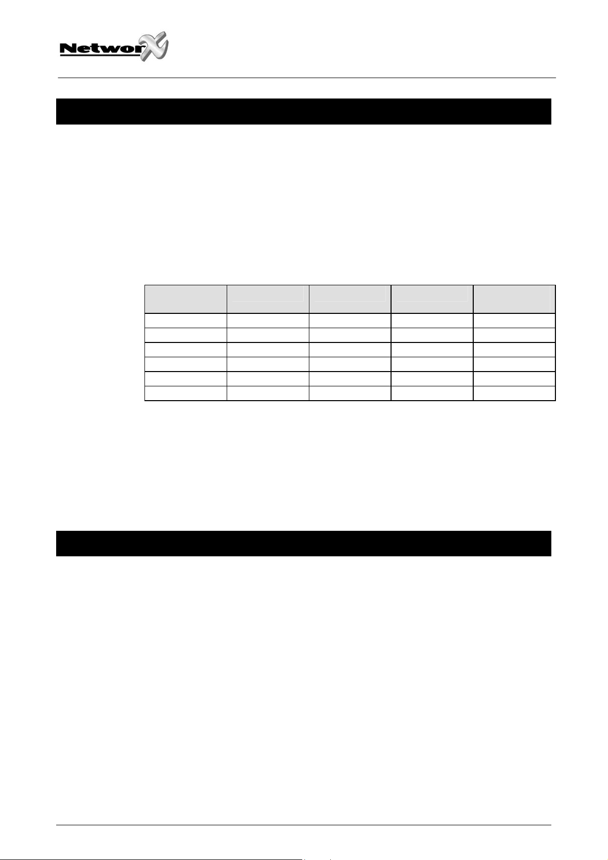
INSTALLING THE NX-216
The first thing that must be decided is the starting zone of this particular zone expander.
The starting zone must be on a boundary of eight (8) zones. The sixteen (16) zones then
move out from this starting position. There are stick-on zone labels to indicate the zone
numbers that you select. To set the starting zone, set the DIP switch according to the
table below:
Note: the position of all switches is only updated when the NX-216 is powered up.
Before you change the position of these switches you must power down the
expander.
Starting zone
number
9 OFF OFF OFF 22
9 ON OFF OFF 23
17 OFF ON OFF 16
25 ON ON OFF 17
33 OFF OFF ON 18
41 ON OFF ON 19
DIP switch 4: DIP switch 4 is used to disable the second block of eight (8) zones on this
zone expander. This can be done if only an eight (8) zone expander is required in a
particular expander location. In this case, up to 5 expanders can be added to the system
creating a total of 48 zones. To disable the second group of eight (8) zones on this
expander, turn DIP switch 4 on.
DIP switch 1 DIP switch 2 DIP switch 3
Module
number
ENROLLING THE NX-216 EXPANDER
For supervision purposes, the presence of all keypads, zone expanders, wireless
receivers, and any other modules connected to the data terminal can automatically be
found and stored in the NX-8’s memory. This allows the control panel to supervise these
modules. To enroll the modules, enter the program mode for the NX-8 control panel as
described in the paragraph of this manual. If necessary, go on to program the rest of the
control panel and the devices. When you exit from program mode, the control panel will
automatically enroll the devices. The enrolling process takes about 12 seconds, during
which time a “Service” indication will be displayed. If a module has been enrolled but it is
not detected by the control, the “Service” indication (LED or LCD screen) will be
displayed.
NX-216 Installation manual Page 4 24/01/05
Page 5

GE Security
g
PROGRAMMING THE NX-216 EXPANDER MODULE
Programming the NX-216 via the LED keypad
ENTERING THE PROGRAM MODE
To enter the program mode, press [*]-[8]. At this time, the five functions LED’s (Stay,
Chime, Exit, Bypass and Cancel) will begin to flash. Next, enter the “Go To Program
Code” (factory default is [9]-[7]-[1]-[3]). If the “Go To Program Code” is valid, the “Service”
LED will flash and the five function LED’s will illuminate steady. You are now in the
program mode and ready to select the module to program.
Note: it is impossible to enter program mode if any partition or the system is armed.
SELECTING THE MODULE TO PROGRAM
Since all modules connected to the NX-8 are programmed through the keypad, the
module you are programming should be the first entry. To program the NX-216 module,
enter the address of the NX-216, followed by [#]. See DIP switch chart on previous page.
PROGRAMMING A LOCATION
Once the number of the module to be programmed has been entered, the “Armed” LED
will illuminate, indicating it is waiting for a programming location to be entered. Any
location can be accessed by directly entering the desired programming location followed
by the pound [#] key. If the location entered is a valid location, the “Armed” LED will
extinguish, the “Ready” LED will illuminate, and the zone LED’s will show the binary data
for the first segment of this location. While entering new data, the “Ready” LED will begin
flashing to indicate a data change in process. The flashing will continue until the new data
is stored by pressing the [*] key. Upon pressing the [*] key, the keypad will advance to the
next segment and display its data. This procedure is repeated until the last segment is
reached. Pressing the [#] key will exit from this location and the “Armed” LED will
illuminate again waiting for a new programming location to be entered. If the desired
location is the next sequential location, press the [Police] key. If the previous location is
desired press the [Fire] key. If the same location is desired press the [Medic] key. To
review the data in a location, repeat the above procedure, pressing the [*] key without any
numeric data entry. Each time the [*] key is pressed, the programming data of the next
segment will be displayed for review.
EXITING A LOCATION
After the last segment of a location is programmed, pressing the [*] key will exit that
location, turn the “Ready” LED off and the “Armed” LED on. As before, you are now ready
to enter another programming location. If an attempt is made to program an invalid entry
for a particular segment, the keypad sounder will emit a triple error beep (beep, beep,
beep) and remain in that segment awaiting a valid entry.
NX-216 Installation manual Page 5 24/01/05
Page 6

EXITING THE PROGRAM MODE
When all the desired changes in programming have been made, it is time to exit the
program mode. Pressing the [Exit] key will exit this programming level, and then return to
the “Select a Module to Program” level. If no additional modules are to be programmed,
pressing the [Exit] key again will exit the program mode. If there is a module to be
programmed, it may be selected by entering its address followed by the [#] key (see
“Selecting the Module To Program” above). The procedure for programming these
devices is the same as for the control panel, except the locations will be for the module
selected.
Note: the timeout for the program mode is 15 minutes.
Programming the NX-216 via the LCD keypad
All steps required for programming are the same as the aforementioned LED keypad. Th e
LCD keypad display will prompt you for the data required. While in the programming
mode, and not in a location, the number in parenthesis is the location you were previously
changing.
GE Security
g
For example: if the display reads “Enter location, then # (5)”, it is reminding you that
location 5 was the last location you programmed. Refer also to “Programming Data”
which follows.
NX-216 Installation manual Page 6 24/01/05
Page 7

Programming data
Programming data is always one of two types. One type of data is numerical, which can
have values from 0-15 or 0-255 depending on the segment size. The other type of data,
feature selection data, is used to turn features on or off. Use the following procedures
with these two data types:
NUMERICAL DATA: Numerical data is programmed by using the numeric keys of the
system keypad to enter a number from 0-255. To view the data in a location, a binary
process is used. With this process, the LED’s for zones 1 through 8 are utilized, and the
numeric equivalents of their illuminated LED’s are added together to determine the data
in a programming location. The numeric equivalents of these LED’s are as follows:
Zone 1 LED = 1 Zone 2 LED = 2 Zone 3 LED = 4 Zone 4 LED = 8
Zone 5 LED = 16 Zone 6 LED = 32 Zone 7 LED = 64 Zone 8 LED = 128
Example:
GE Security
g
If the numerical data to be programmed in a location is “66”, press [6] - [6] on the keypad.
The LED’s for zone 2 and zone 7 will become illuminated indicating 66 is in that location
(2 + 64 = 66).
Once the data is programmed, press the [*] key to enter the data and advance to the next
segment of that location. After the last segment of a location is programmed, pressing the
[*] key will exit that location, turn the “Ready” LED off and the “Armed” LED on. As before,
you are now ready to enter another programming location. If an attempt is made to
program a number too large for a particular segment, the keypad sounder will emit a triple
beep, indicating an error, and remain in that segment awaiting a valid entry.
Remark: on the LCD keypad, the number in the location will be displayed. For locations
with a maximum of 15, the hexadecimal equivalent will be displayed in parenthesis.
Example: 11 (B) or 14 (E).
FEATURE SELECTION DATA: Feature selection data will display the current condition
(on or off) of eight features associated with the programming location and segment
selected. Pressing a button on the keypad (1 through 8) that corresponds to the “feature
number” within a segment will toggle (on/off) that feature. Pressing any numeric key
between [1] and [8] for selection of a feature will make the corresponding LED illuminate
(feature ON). Press the number again, and the LED will extinguish (feature OFF). You will
see that numerous features can be selected from within one segment. For instance, if all
eight features of a segment are desired, pressing [1] - [2] - [3] - [4] - [5] - [6] - [7] - [8] will
turn on LED’s 1 through 8 as you press the keys, indicating that those features are
enabled.
LCD keypad users note: the numbers of the enabled features will be displayed. However,
the features not enabled will display a hyphen (-).
After the desired setting of features is selected for this segment, press the [*] key. This
will enter the data and automatically advance to the next segment of the location. When
you are in the last segment of a location and press the [*] to enter the data, you will exit
that location. This will now turn the “Ready” LED off and the “Armed” LED on. As before,
you are now ready to enter another programming location.
NX-216 Installation manual Page 7 24/01/05
Page 8

GE Security
g
ZONE CONFIGURATIONS AND PARTITION SELECTION
Zones can be assigned to different zone configurations (zone types). The programming
for all zone information is performed in the control panel. For instructions on accessing
and programming the NX-8, as well as changing the characteristics of a configuration
group, refer to the NX-8 installation manual.
TERMINAL DESCRIPTION
TERMINAL DESCRIPTION
POS Connect to the KP POS terminal of the control panel. Current draw is 30 mA.
COM Connect to the KP COM terminal of the control panel.
DATA
TAM Connect as shown below. If not used, co nnect to a COM terminal.
AUX
Z9
COM Common (-) terminal for zones 9 & 10.
Z10
Z11-Z24 Connect as described for Z9 & Z10.
Connect to the KP DATA terminal of the control panel (see the wiring diagram for wire
specifications).
Can be used to power devices directly from the NX-216. Power is coming from the control
panel, therefore the current draw of these devices must be added to the total current draw of
the NX-216. This output is current limited to 100 mA.
Connect to one side of zone 9 loop. Connect the other side to COM terminal. Open or short
causes alarm (see wiring diagram for examples).
Connect to one side of zone 10 loop. Connect the other side to COM terminal. Open or short
causes alarm (see the wiring diagram for examples).
NX-216 Installation manual Page 8 24/01/05
Page 9

GE Security
g
NX-216 PRINT LAYOUT
TECHNICAL SPECIFICATIONS
Power supply (supplied from NX-8 control panel or NX-320 power supply):
• nominal:
• minimum/maximum:
12 Vdc Auxiliary power output (supplied from NX-8 control panel or NX-320 power supply):
• max. current consumption:
Current consumption:
• typical:
Loop resistance: 300 Ohm maximum
Loop response: selectable 50 ms or 500 ms
Operating temperature: 0 - 50° C
Dimensions (LxWxH): 154 x 54 x 20 mm
Weight: 66 g
12 Vdc
9 Vdc - 14 Vdc
100 mA restricted by NX-216
34 mA
NX-216 Installation manual Page 9 24/01/05
Page 10

GE Security
g
CE DECLARATION
NX-216 Installation manual Page 10 24/01/05
Page 11

GE Security
GE Security
g
g
NX-216 Installation manual Page 11 24/01/05
NX-216 Installation manual Page 11 24/01/05
Page 12

GE Security
GE Security
g
g
NX-216 Installation manual Page 12 24/01/05
NX-216 Installation manual Page 12 24/01/05
Page 13

GE Security
g
NX-216 Installation manual Page 13 24/01/05
Page 14

www.gesecurity.com
EMEA Distribution is a division of GE Security EMEA bvba
COPYRIGHT ©2005
© GE Security EMEA bvba. All rights reserved. GE Security EMEA bvba grants the right to reprint this
manual for internal use only. GE Security EMEA bvba reserves the right to change information without
notice.
 Loading...