

Page 1
P/N INX208EIM • REV E • NOV12
NX-208E Two-Wire Smoke Loop Expander
Gauge
Ohms per/1000 feet
12
1.0588
13
2.003
14
2.525
15
3.184
16
4.016
18
6.385
20
10.15
Installation and Startup
Product summary
The NX-208E is a microprocessor-controlled 2-wire smoke
expander for the NetworX NX-6, NX-8, and NX-8E control
panels. One NX-208E module can be added to the NX control
panel with a maximum zone count of 8 zones. Each expander
has an optional tamper input making it ideal for use in a remote
location.
Note: Do not add normally open contact devices to an NX208E loop (i.e. sounder, heat detectors, pull stations, water
flow devices, etc.
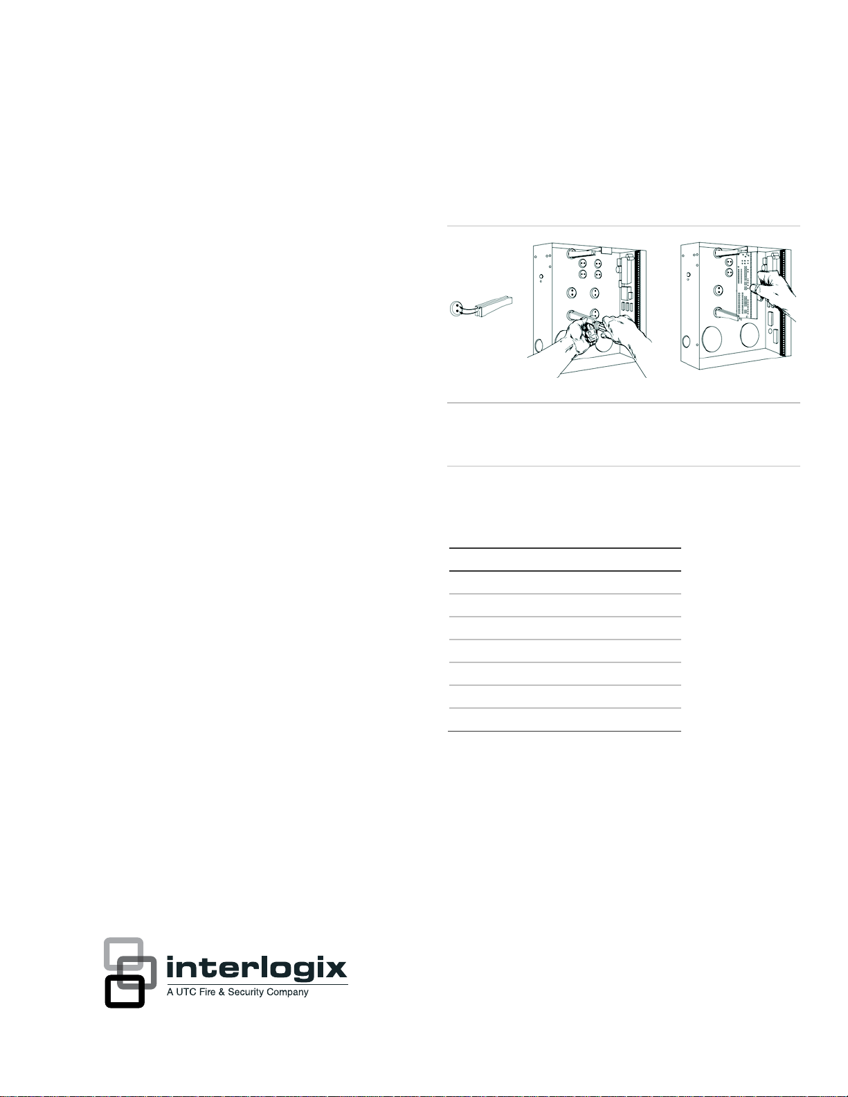
Installation guidelines
Inside the can, several 2-holed insertion points have been
constructed. This allows for either vertical or horizontal
placement of the modules. Notice that each insertion point has
two sizes of holes -a larger hole and a smaller hole. (Figure 1
below).
1. The black plastic PCB guides are grooved on one edge
where the PC board will be seated. The end with the halfmoon protrusion fits into the larger hole. The smaller hole
is for the screw.
Figure 1: Board installation
Caution: You must be free of static electricity before handling
circuit boards. Wear a grounding strap or touch a bare metal
surface to discharge static electricity.
Wiring references
The following references were taken from the “Reference Data
for Radio Engineers ” (6th edition).
2. Place the first black plastic PCB guide in the top insertion
point, grooved edge downward. The half-moon protrusion
will be in the large hole. It does not require force. Insert
one of the provided screw into the smaller hole (from
inside the can) to secure it in place. A screwdriver should
reach through the notch that runs the length of the guide
to tighten the screw. The second PBC guide should be
positioned opposite the first (grooved edge up) and placed
in the lower insertion point, using the same procedures
described above. Once mounted, screw it in securely.
3. The PC Board should slide freely in the grooves of both
guides.
Page 2
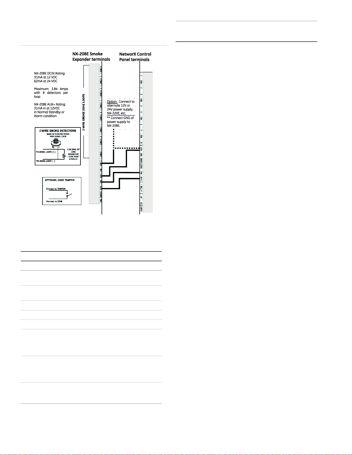
Wiring connections
Terminal
Descriptions
COM
TAMPER
Connect normally closed tamper switch between this
pin and COM.
DATA
Connect to the DATA terminal of the control panel. (See
Figure 2 above)
COM
Connect to the COM terminal of the control panel.
AUX+
Connect to the AUX+ terminal of the control panel.
COM
DCIN
Connect to the AUX PWR+ terminal of the control
panel. Optionally, connect to an auxiliary 12V or 24V
power supply (i.e. NX-320E, etc).
Be sure to connect GND of pow er supply to NX-208E.
ZONE8-
Connect (Zone 8 negative) to negative side of smoke
detector. Open (trouble) or short (alarm) causes a
smoke condition and sounds the keypad by default, but
is programmable. (See Figure 2 above)
ZONE8+
Connect (Zone 8 positive) to the positive side of the
smoke detector. Open or short causes a smoke
condition and sounds the keypad. (See Figure 2 above)
ZONE7through
ZONE1+
Connect as described above for ZONE8- & ZONE8+.
Figure 2: Wiring connections
Enrolling the module
The NetworX control panels have the ability to automatically
find and store in memory the presence of all keypads, zone
expanders, wireless receivers and any other module
connected to the data terminal. This allows these modules to
be supervised by the control panel.
To enroll the modules, enter the Program Mode of the control
panel (refer to the installation manual for the specific control
panel). When the Program Mode is exited, it will automatically
enroll the devices. The enrolling process takes about 12
seconds, during which tim e the “Service” LED will illum inate.
User codes will not be accepted during the enrolling process.
Once a module is enrolled, if it is not detected by the control
panel the “Service” LED will illuminate.
Module address
This 2-wire smoke module has a fixed address of 95. When
programming the expander module, enter the Program Mode
and select the device address as 95. (Refer to "Programming
Mode" section for further details.)
Programming mode
Terminal descriptions
Table 1: Terminal descriptions
1. To enter the program mode, press [�]-[8]. All of the
function key LEDs will begin to flash.
2. Enter the "Go To Program" code (factory default is [9]-[7][1]-[3]). If the code was valid, the Service LED will flash,
and the function LEDs will illuminate steady, indicating the
device to program should be entered.
3. Press [9]-[5]-[#] for the fixed address of the 2-wire smoke
module. The Armed LED will illuminate while it is waiting
for a programming location to be entered.
4. Enter the desired programming location. The Armed LED
will begin to flash while a programming location is being
entered.
5. Press [#]. If this is a valid location, the Armed LED will
extinguish, the Ready LED will illuminate, and the binary
data for the first segment of this location will be shown on
the zone LEDS.
6. To change the data, enter the data followed by [�]. The
data will be entered, and the location will automatically
increment to the next segment. The data for that segment
will be displayed. This procedure is repeated until the last
segment is reached. Pressing the [#] key will exit from this
location. To review the data, repeat the above procedure,
pressing the [�] key without entering data first. Each time
the [�] key is pressed the next segment is displayed.
2 NX-208E Two-Wire Smoke Loop Expander Installation and Startup
Page 3

Programming data is always one of two types of data. The first
1 = Zone 1
3 = Zone 3
5 = Zone 5
7 = Zone 7
2 = Zone 2
4 = Zone 4
6 = Zone 6
8 = Zone 8
0 = Zones 1-8
8 = Zones 65-72
16 = Zones 129-136
1 = Zones 9-16
9 = Zones 73-80
17 = Zones 137-144
2 = Zones 17-24
10 = Zones 81-88
18 = Zones 145-152
3 = Zones 25-32
11 = Zones 89-96
19 = Zones 153-160
4 = Zones 33-40
12 = Zones 97-104
20 = Zones 161-168
5 = Zones 41-48
13 = Zones 105112
21 = Zones 169-176
6 = Zones 49-56
14 = Zones 113120
22 = Zones 177-184
7 = Zones 57-64
15 = Zones 121128
23 = Zones 185-192
Loc
Description
Default
Your data
0
ZONE ENABLE
(see Table 2
above)
0 (disabled)
1
BANK
SELECTION
(see Table 3
above)
1
2
SPECIAL
FLAGS (See
“Location 2
Special Flags”
above)
0 (disabled)
type is numerical, and can take on values from 0-255 or 0-15
depending on the segm ent s ize. The second type is a feature
selection type. Feature selection data is used to turn features
on or off.
LCD Keypad Users: All steps required for programming are
the same as the aforementioned LED keypad. The LCD
keypad display will prompt you for the data required. While in
the programming mode, and not in a location, the number in
parenthesis is the location you were previously changing. For
example, if the display reads "Enter location, then # (5)", it is
reminding you that location 5 was the last location you
programmed. In feature selection data, the numbers of the
enabled features will be dis played. However, the features not
enabled will dis play a hyphen (-).
Programming location guide
The programming for all zone information is performed in the
NetworX control panels. For instructions on accessing and
programming the control panel as well as changing the
characteristics of a configuration group, refer to the installation
manual for the corresponding control panel.
LOCATION 0 - ENABLING THE ZONES (LOOPS)
(1 segment, feature selection data) Location 0 is used to
enable / disable the zone(s). Factory default = all zones
disabled.
Table 2: Location 0
Location 2 Special Flags
(1 segment, feature selection data) Location 2 is used to select
special flags for communication. Factory default = all flags
disabled.
Note: Seg 1 - 24V Configuration requires a total of four 12V,
17AH batteries – Connect 2 batteries in parallel, and connect
the other 2 batteries in parallel. Then connect those two sets in
series.
1 = enables the 24 V power supply option (see Note)
2 = disables the temporal
3 = enables temporal regardless of panel programming
4 = enables tamper
5 = disables voltage reversal (not perform voltage reversal
functions when in alarm; used in con-junction with smokes that
have sounders)
Compatible smoke detector list
• S09A Compatible Devices 429AT, 521B/BXT (SW1 ON),
21NB/NBXT
• S10A Compatible Devices S21NB,521NBXT,521NCSXT,
429C, 429CT, 521B/BXT (SW1 OFF), 711U/UT, 721U/UT
• S11A Compatible Devices 429CRT,429CST, 521CRXT,
521NCRXT, 521NCSRXT, 731U
LOCATION 1 - SETTING THE ZONE BANK DURING
COMMUNICATION
(1 segment, numerical data) Location 1 is used to select the
bank used by zones 1-192 during communication. A zone may
reside in any one of the 24 banks.
Note: If you enter [1] through [23], then zones 1-8 in location 0
become the corresponding zones as shown in the following
chart. Example: Entering [9] in Location 1 causes zone 1 to
become zone 73, and zone 8 becomes 80. Factory default = 1
(Zones 9-16).
Table 3: Location 1
NX-208E Two-Wire Smoke Loop Expander Installation and Startup 3
Programming worksheet
Table 4: Programming worksheet
Loc 2, Seg 1 - 24V Configuration requires a total of four 12V, 17AH
batteries – Connect 2 batteries in parallel, and connect the other 2
batteries in parallel. Then connect those two sets in series.
Page 4

Specifications
Operating Pow er
12VDC Supplied from NetworX models:
NX-6, NX-8, NX-8E, or NX-320E
IMPORTANT: Supplied power from external
supplies must be UL listed for Fire or
Burglary.
Auxiliary Power
Supplied from NetworX models:
NX-6, NX-8, NX-8E, or NX-320E; Current
limited to 100mA
Current Draw
30 mA
DCIN Current Draw
31mA maximum @ 12VDC
62mA maximum @ 24VDC
3.84 Amps MAX (w ith 8 detectors per loop)
AUX+ Rating
13mA @ 12VDC in Normal Standby
53mA @ 12VDC in Alarm
Loop Resistance
12 Volt Loop = 20 Ohms Maximum
24 Volt Loop = 50 Ohms Maximum
Loop Response
180mS
Operating
Temperature
32 to 120 degrees F
Dimensions
9.5" Wide
3.5" High
1.0" Deep
Shipping Weight
2 lbs.
UL listings
UL609 Local Grade A Mercantile, Police Station
Connect with Basic Line Security (* requires #NX003-C enclosure)
UL985 Household Fire Warning Systems & Units
UL1023 Household Burglary Alarm Systems &
Units
UL1610 Central Station Burglar Alarm Unit
Canada/ULC
listings
S303 Local Burglar Alarm Units and Systems
S545 Standard for Residential Fire Warning
System Control Units
Part #
Description
NX-208E
Two Wire Smoke Loop Expander
EOL33
3.3K End-of-Line Resistor device
Other available NetworX modules
NX-216E
16 Zone Expander Module
NX-320E
Smart Power Supply and Buss Extender
NX-507E
Seven Relay Module
Ordering information
Contact information
www.utcfireandsecurity.com or www.interlogix.com
For customer support, see www.interlogix.com/customer-
support
© 2012 UTC Fire & Security Americas Corporation, Inc.
Interlogix is part of UTC Climate Controls & Security, a unit of
United Technologies Corporation. All rights reserved.
Regulatory information
4 NX-208E Two-Wire Smoke Loop Expander Installation and Startup
 Loading...