

Page 1

Raptor A
T
Motherboard
Installation Guide
Page 2

Page 3

Introduction
I
Table of Contents
Notice
...................................................... IV
Introduction
.......................................... V
Chapter 1 Pre-Configuration
......1
Step 1 Setting the Jumpers
3
Jumper Locations ............................................................. 4
CMOS Reset....................................................................... 5
Disk-on-Chip Selection..................................................... 5
Flash BIOS Write Protect ................................................. 5
Clock Speed Selection ..................................................... 6
Watchdog Timer Selection............................................... 6
On-board Ethernet ............................................................ 7
ATX Power Supply Enhancements ................................. 7
Step 2
DRAM, CPU, Disk-on-Chip and
Cables Installation
8
Raptor AT Memory Configuration ................................... 8
CPU Installation ................................................................ 8
Disk-on-Chip installation................................................ 10
Installing Cables ............................................................. 10
Power and Control Panel Cables................................... 10
Installing Peripheral Cables........................................... 10
Index of Connectors ....................................................... 13
Chapter 2 HIFLEX BIOS
Setup
............................15
Standard Setup ............................................................... 16
Advanced CMOS Setup .................................................. 17
Advanced Chipset Setup................................................ 21
Power Management Setup ............................................. 25
PCI/Plug and Play Setup ................................................ 28
Peripheral Setup ............................................................. 31
Auto Detect Hard Disk .................................................... 34
Page 4

Raptor AT – Installation Guide
II
Change User Password.................................................. 34
Change Supervisor Password ....................................... 35
Change Language Settings............................................ 35
Auto Configuration with Optimal Settings ................... 35
Auto Configuration with Fail-Safe Settings.................. 36
Save Settings and Exit ................................................... 36
Exit without Saving......................................................... 36
Chapter 3 Upgrading
....................37
Upgrading the System Memory..................................... 37
Upgrading the Microprocessor...................................... 37
Appendix A Technical
Specifications
..........39
Chipsets ........................................................................... 39
System Memory .............................................................. 39
Bios .................................................................................. 39
Embedded I/O .................................................................. 40
Industrial Devices ........................................................... 41
Miscellaneous ................................................................. 41
Memory Map .................................................................... 43
DMA Channels................................................................. 43
I/O Map ............................................................................. 44
On-board Devices ........................................................... 45
PCI Configuration Space Map........................................ 45
Interrupts ......................................................................... 46
PCI Interrupt Routing Map ............................................. 46
SMBUS ............................................................................. 47
Connectors Pin-out......................................................... 47
Appendix B Flash BIOS
programming
...........51
Appendix C Disk-On-Chip
.........53
Page 5

Introduction
III
Appendix D On-Board Industrial
Devices
.......................55
Watchdog Timer.............................................................. 55
Post Code Display .......................................................... 56
Appendix E
On-Board
Ethernet
.................67
Page 6

Raptor AT – Installation Guide
IV
Notice
The company reserves the right to revise this publication or to change
its contents without notice. Information contained herein is for
reference only and does not constitute a commitment on the part of the
manufacturer or any subsequent vendor. They are in no way
responsible for any loss or damage resulting from the use (or misuse) of
this publication.
This publication and any accompanying software may not, in whole or
in part, be copied, photocopied, translated or reduced to any machine
readable form without prior consent from the vendor, manufacturer or
creators of this publication, except for copies kept by the user for
backup purposes.
Brand and product names mentioned in this publication may or may not
be copyrights and/or registered trademarks of their respective
companies. They are mentioned for identification purposes only and are
not intended as an endorsement of that product or its manufacturer.
Third Edition.
August, 2001
Page 7

Introduction
V
Introduction
Thank you for your purchase of the Raptor AT industrial embedded
motherboard. The Raptor AT design was based on the Intel 440BX
chipset providing the ideal platform to industrial applications. The
Raptor AT design is based on the Intel Celeron and PIII processor.
With proper installation and maintenance, your Raptor AT will provide
years of high performance and trouble free operation.
This manual provides a detailed explanation into the installation and
use of the Raptor AT industrial embedded motherboard. This manual
is written for the novice PC user/installer. However, as with any major
computer component installation, previous experience is helpful and
should you not have prior experience, it would be prudent to have
someone assist you in the installation. This manual is broken down into
3 chapters and 5 appendixes.
Chapter 1 - System Board Pre-Configuration
This chapter provides all the necessary information for
installing the Raptor AT. Topics discussed include: installing
the CPU (if necessary), DRAM installation, jumper settings
for CPU and standard I/O. Connecting all the cables from the
system board to the chassis and peripherals.
Chapter 2 - BIOS Configuration
This chapter shows the final step in getting your system
firmware setup.
Chapter 3 - Upgrading
The Raptor AT provides a number of expansion options
including memory. All aspects of the upgrade possibilities are
covered.
Page 8

Raptor AT – Installation Guide
VI
Appendix A - Technical Specifications
A complete listing of all the major technical specifications of
the Raptor AT is provided.
Appendix B - Flash BIOS Programming (optional)
Provides all the information necessary to program your
optional AMIBIOS Flash BIOS.
Appendix C - Disk-on-Chip
Two on-board sockets for a solid state flash disk device.
Appendix D - Industrial Devices
Watchdog Timer and On-Board POST (Power On Self
Testing) code display.
Appendix E - Ethernet
On-board 10/100 Ethernet.
Static Electricity Warning!
The Raptor AT has been designed as rugged as possible but can still be
damaged if jarred sharply or struck. Handle the motherboard with care.
The Raptor AT also contains delicate electronic circuits that can be
damaged or weakened by static electricity. Before removing the Raptor
AT from its protective packaging, it is strongly recommended that you
use a grounding wrist strap. The grounding strap will safely discharge
any static electricity build up in your body and will avoid damaging the
motherboard. Do not walk across a carpet or linoleum floor with the
bare board in hand.
Page 9

Introduction
VII
Warranty
This product is warranted against material and manufacturing defects
for two years from the date of delivery. Buyer agrees that if this
product proves defective the manufacturer is only obligated to repair,
replace or refund the purchase price of this product at manufacturer's
discretion. The warranty is void if the product has been subjected to
alteration, misuse or abuse; if any repairs have been attempted by
anyone other than the manufacturer; or if failure is caused by accident,
acts of God, or other causes beyond the manufacturer's control.
Raptor AT - An Overview
The Raptor AT represents the ultimate in industrial embedded
motherboard technology. No other system board available today
provides such impressive list of features:
CPU Support
• Supports full series of Intel Celeron and PIII PGA370
processors (up to 100MHz FSB).
Supported Bus Clocks
• 66 and 100MHz.
Memory
• Three DIMM sockets up to 384MB or 768MB(registered)
SDRAM, PC100 recommended (required for PIII or 100MHz).
On-Board I/O
• 2 Floppies up to 2.88 MB.
• Dual channel PCI 32-bit EIDE controller.
• Two high speed RS-232 serial ports 16 Bytes FIFO (16550).
• One Centronics™ compatible bidirectional parallel port.
EPP/ECP mode compatible.
Page 10

Raptor AT – Installation Guide
VIII
• One PS/2 mouse header and one AT keyboard connector.
• Two Universal Serial Bus headers.
• Two Disk-on-Chip on-board sockets up to 288MB each with
FFS for diskless applications.
• Software and hardware programmable Watchdog Timer & onboard POST Display Diagnostics.
• Four 16-bit ISA slots and four 32-bit PCI slots.
• Ethernet header.
• Power Button – advanced management support.
• Automatic CPU voltage & temperature monitoring device
(optional).
ROM BIOS
• AMI BIOS™ BIOS HIFLEX with optional FLASH ROM
On-Board Ethernet
• On-board 10/100 Ethernet.
Conventions Used in this Manual
8
Notes - Such as a brief discussion of memory types.
Important Information - such as static warnings, or
very important instructions.
When instructed to enter keyboard keystrokes, the
text will be noted by this graphic.
Page 11

Chapter 1: Pre-Configuration
1
Special Warranty Note:
Products returned for warranty repair will b
e
inspected for damage caused by imprope
r
installation and misuse as described in th
e
previous section and the static warning below.
Should the board show signs of abuse, th
e
warranty will become void and the customer wil
l
be billed for all repairs and shipping an
d
handling costs.
Chapter 1 Pre-Configuration
This chapter provides all the necessary information for installing the
Raptor AT into a standard PC chassis. Topics discussed include:
installing the CPU (if necessary), DRAM installation, jumper settings
for CPU and standard I/O.
Handling Precautions
The Raptor AT has been designed to be as rugged as possible but it can
be damaged if dropped, jarred sharply or struck. Damage may also
occur by using excessive force in performing certain installation
procedures such as forcing the system board into the chassis or placing
too much torque on a mounting screw.
Take special care when installing or removing the system memory
DIMMs. Never force a DIMM into a socket. Screwdrivers slipping off
a screw and scraping the board can break a trace or component leads,
rendering the board unusable. Always handle the Raptor AT with care.
Static Warning
The Raptor AT contains delicate electronic semiconductors that are
highly sensitive to static electricity. These components, if subjected to a
static electricity discharge, can be weakened thereby reducing the
serviceable life of the system board. BEFORE THE BOARD IS
REMOVED FROM ITS PROTECTIVE ANTISTATIC PACKAGING,
Page 12

Raptor AT – Installation Guide
2
TAKE PROPER PRECAUTIONS! Work on a conductive surface that
is connected to the ground. Before touching any electronic device,
ground yourself by touching an unpainted metal object or, and highly
recommended, use a grounding strap.
Page 13

Chapter 1: Pre-Configuration
3
Step 1 Setting the Jumpers
Your Raptor AT is equipped with a large number of peripherals and has
the ability to run at a variety of speeds without the need to change any
crystals or oscillators. As such, there are a large number of
configuration jumpers on the board. Taken step by step, setting these
jumpers is easy. We suggest you review each section and follow the
instructions.
Jumper Types
Jumpers are small copper pins attached to the system board. Covering
two pins with a shunt closes the connection between them. The Raptor
AT examines these jumpers to determine specific configuration
information. There are three different categories of jumpers on the
Raptor AT.
A. Two pin jumpers are used for binary selections such as enable,
disable. Instructions for this type of jumper are open, for no shunt over
the pins or closed, when the shunt covers the pins.
B. Three or four pin jumpers are used for multiple selections.
Instructions for these jumpers will indicate which two pins to cover.
For example: for JPx 2-3 the shunt will be covering pins 2 and 3
leaving pins 1 and 4 exposed.
C. Grouped jumpers are used when a certain function has multiple
selections. There are two grouped jumpers on the board and careful
attention should be given when setting these jumpers. Instructions for
grouped jumpers are similar to those above.
How to identify pin number 1 on Figure 1-1: Looking to the solder side
(The board side without components) of the PCB (Printed Circuit
Board), pin number 1 will have a squared pad J. Other pins will have
a circular pad Q. They are numbered sequentially.
Page 14
Raptor AT – Installation Guide
4
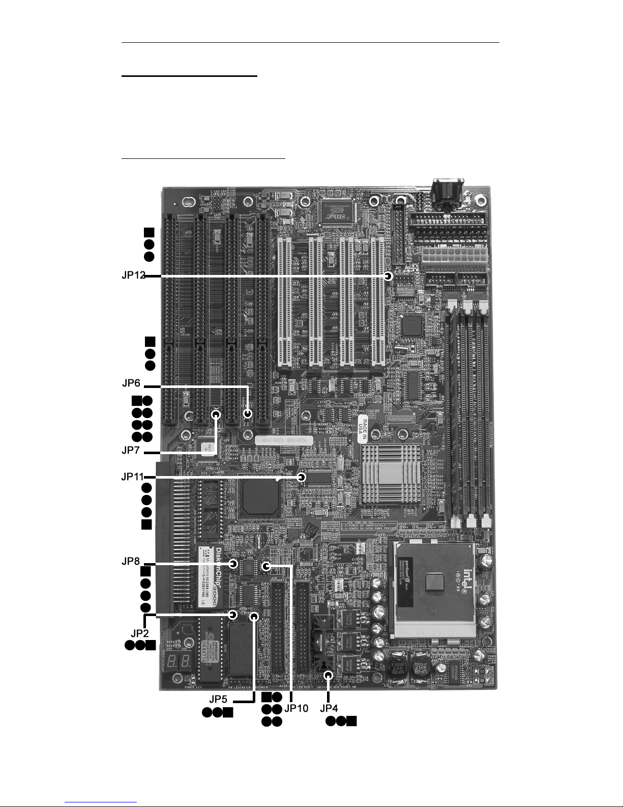
Jumper Locations
Use the diagram below and the tables on the following pages to locate
and set the on-board configuration jumpers.
Figure 1-1 Jumper Locations
Page 15

Chapter 1: Pre-Configuration
5
CMOS Reset
This option is provided as a convenience for those who need to reset
the CMOS registers. It should always be set to "Normal" for standard
operation. If the CMOS needs to be reset, turn off the system, move
JP5 to 2-3, turn the system on, move jumper to 1-2 and press reset.
Table 1-1 CMOS Reset
Reset CMOS Normal Clear CMOS
JP5 1-2* 2-3
* Manufacturer's Settings.
Disk-on-Chip Selection
The jumper JP7 allows selection for the addresses on Disk-on-Chip
devices.
Table 1-2 Disk-on-Chip Selection
Addresses
JP7
1-2
JP7
3-4
JP7
5-6
JP7
7-8
D000h/D400h* Closed Open Open Open
D400h/D800h Open Closed Open Open
D800h/DC00h Open Open Closed Open
DC00h/D000h Open Open Open Closed
* Manufacturer's Settings.
Flash BIOS Write Protect
To program the optional flash BIOS (Location U9 – Figure 1-2) use
JP2 to disable write protection. For regular standard BIOS use default
settings.
Table 1-3 Flash BIOS Programming Selection
Flash
Write-protect
Enabled Disabled
JP2 1-2* 2-3
*Manufacturer's Settings.
Page 16
Raptor AT – Installation Guide
6
Clock Speed Selection
The Raptor AT has a CPU automatic speed selector device. The jumper
JP11 allows selection for this option.
Table 1-4 Clock Frequency Selection
Clock
Frequency
JP11
1-2
JP11
2-3
JP11
3-4
AUTODETECT* Closed Open Open
66MHz Open Closed Open
100MHz Open Open Closed
* Manufacturer's Settings.
Watchdog Timer Selection
The watchdog timer can be set as hardware, software or disabled
through JP10. JP8 sets the time-out and JP6 sets the addresses. Please
refer to appendix D for more details.
Table 1-5 Watchdog Timer Selection
Watchdog
Type
JP10
1-2
JP10
3-4
JP10
5-6
Hardware Closed Open Open
Disabled* Open Closed Open
Software Open Open Closed
* Manufacturer's Settings.
Table 1-6 Watchdog Time-out Selection
Watchdog
Timeout
JP8
1-2
JP8
2-3
JP8
3-4
1200 ms* Closed Open Open
600 ms Open Closed Open
150 ms Open Open Closed
* Manufacturer's Settings.
Page 17

Chapter 1: Pre-Configuration
7
Table 1-7 Watchdog Address Selection
Watchdog
Address
JP6
1-2
JP6
2-3
110h* Closed Open
310h Open Closed
* Manufacturer's Settings.
On-board Ethernet
The Raptor AT has a built-in 10/100 Ethernet. The jumper JP12 either
disables (2-3) or enables (1-2) this feature. For more information please
refer to Appendix E.
Table 1-8 Ethernet Selection
Ethernet
Selection
Enabled Disabled
JP12 1-2* 2-3
* Manufacturer's Settings.
ATX Power Supply Enhancements
The Raptor AT has a Power on mode selection. The jumper JP4 selects
the power on mode.
Table 1-9 POWER ON Mode Select
Power on
mode
Power on
immediately
Power on upon
PWR_SW signal
(Button press)
JP4 1-2* 2-3
* Manufacturer's Settings.
Page 18

Raptor AT – Installation Guide
8
The Raptor AT uses standard DIMMs. To determine the
actual capacity of a 1 by 64 DIMM, simply multiply the
1MB by 8.
Step 2 DRAM, CPU, Disk-on-Chip and
Cables Installation
Depending upon how your Raptor AT is configured you may need to
install the following:
• DRAM (DIMMs)
• CPU
• Disk-on-chip
Raptor AT Memory Configuration
The Raptor AT offers 3 DIMM memory sockets (Locations J28,
J27 and J26 – Figure 1-2). They can be configured with 3.3V
unbuffered SDRAM modules. It is very important that the quality
of the DIMMs is good. Unreliable operation of the system may
result if poor quality DIMMs are used. Always purchase your
memory from a reliable source. We strongly recommend using
PC100 memory module (REQUIRED when using PIII or 100MHz
operation). The Raptor AT also supports ECC memories.
CPU Installation
The Raptor AT currently supports the following CPUs:
• Full series of Intel Celeron and PIII processors (PGA 370).
1. Improper installation of the CPU may cause
p
ermanent damage to both the system board and the
CPU. -- Void of warranty
2. Always handle the CPU by the edges, never touch the
pins.
3. Always use a heatsink and a CPU fan.
Page 19

Chapter 1: Pre-Configuration
9
Locate the CPU socket on your Raptor AT system board (PGA Socket
– Location U21 – Figure 1-2). To install the processor, lift the lever of
the ZIF socket and gently insert the CPU. The CPU will fit only in the
right alignment. Make sure the CPU is inserted all the way. Lower the
lever. Install the CPU fan. Make sure it is locked and connected to J3
(see pin-out in Appendix A).
The continued push of technology to increase performance levels
(higher operating speeds) and packaging density (more transistors) is
aggravating the thermal management of the CPU. As operating
frequencies increase and packaging sizes decreases, the power density
increases and the thermal cooling solution space and airflow become
more constrained. The result is an increased importance on system
design to ensure that thermal design requirements are met for the CPU.
The objective of thermal management is to ensure that the temperature
of the processor is maintained within functional limits. The functional
temperature limit is the range within which the electrical circuits can be
expected to meet their specified performance requirements. Operation
outside the functional limit can degrade system performance, cause
logic errors or cause component and/or system damage. Temperatures
exceeding the maximum operating limits may result in irreversible
changes in the operating characteristics of the component.
If the Raptor AT industrial embedded motherboard is acquired without
the CPU and the thermal solution, extremely care must be taken to
avoid improper thermal management. All Intel thermal solution
specifications, design guidelines and suggestions to the CPU being
used must be followed. The Raptor AT warranty is void if the thermal
management does not comply with Intel requirements.
Designing for thermal performance
In designing for thermal performance, the goal is to keep the processor
within the operational thermal specifications. The inability to do so will
shorten the life of the processor.
Fan Heatsink
An active fan heatsink can be employed as a mechanism for cooling the
Intel processors. This is the acceptable solution for most chassis.
Adequate clearance must be provided around the fan heatsink to ensure
unimpeded air flow for proper cooling.
Page 20

Raptor AT – Installation Guide
10
Airflow management
It is important to manage the velocity, quantity and direction of air that
flows within the system (and how it flows) to maximize the volume of
air that flows over the processor.
Thermal interface management
To optimize the heatsink design for the Celeron/Pentium III processor,
it is important to understand the impact of factors related to the
interface between the processor and the heatsink base. Specifically, the
bond line thickness, interface material area, and interface material
thermal conductivity should be managed to realize the most effective
thermal solution.
This completes the installation of the CPU. Now is it a good time to
double check both the CPU and DIMM installation to make sure that
these devices have been properly installed.
Disk-on-Chip installation
The Raptor AT supports Two Disk-on-Chip on-board up to 288 MB
each with FFS for diskless applications.
Locate the Disk-on-Chip socket on your Raptor AT system board
(Locations U12 and U13 - Figure 1-2). Locate pin 1 (Figure 1-2). To
install the Disk-on-Chip gently insert the chip. Make sure the Disk-onChip is inserted all the way.
Installing Cables
Power and Control Panel Cables
The Raptor AT gets power either from the power ATX connector J7 or
the power AT connector J41.
Installing Peripheral Cables
Now it is a good time to install the internal peripherals such as floppy
and hard disk drives. Do not connect the power cable to these
peripherals, as it is easier to attach the bulky ribbon cables before the
smaller power connectors. If you are installing more than one IDE
drive double check your master/slave jumpers on the drives. Review
Page 21

Chapter 1: Pre-Configuration
11
the information supplied with your drive for more information on this
subject.
Connect the floppy cable (not included) to the system board. Then
connect remaining ends of the ribbon cable to the appropriate
peripherals. Connect the Ethernet cable (included). Connect the mouse
(included) and the parallel/2 serial cable (included). Finally, connect
the IDE cable (not included) to the system. Then connect remaining
ends of the ribbon cable to the appropriate peripherals. This concludes
the hardware installation of your Raptor AT system. Now it is a good
time to re-check all of the cable connections to make sure they are
correct.
Page 22
Raptor AT – Installation Guide
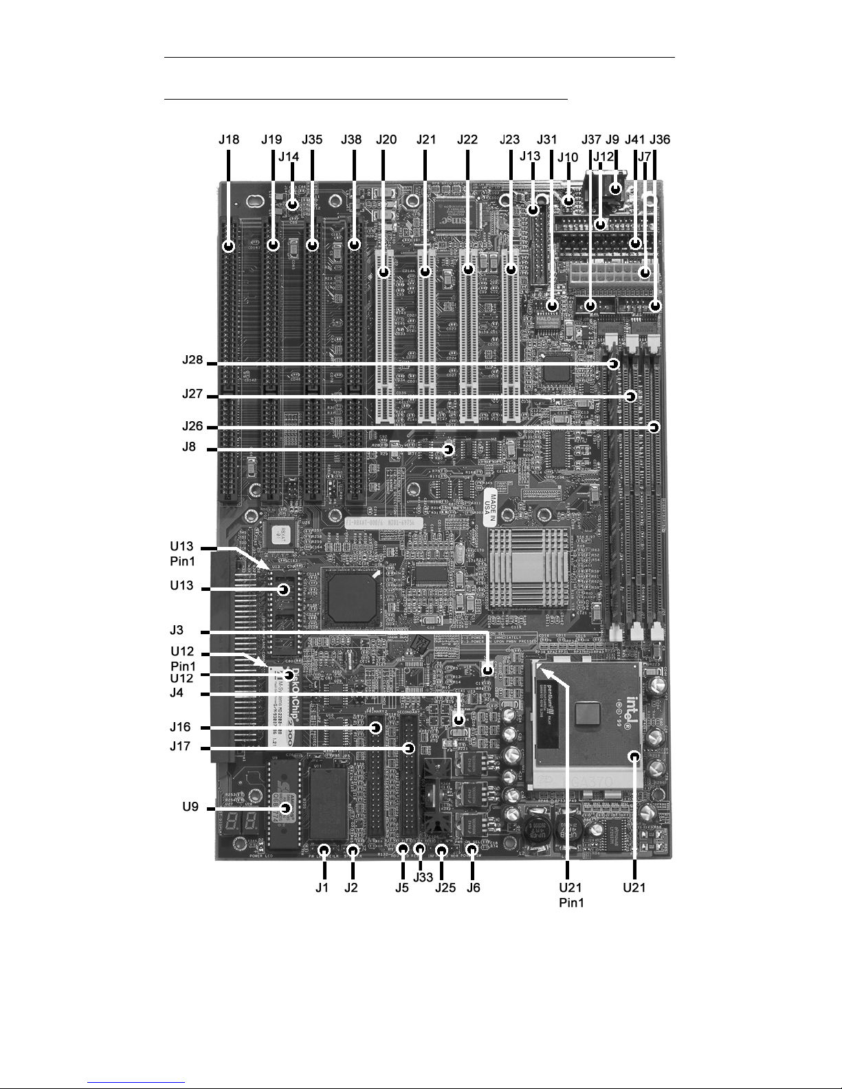
12
Figure 1-2 Location of Components and Connectors
Page 23

Chapter 1: Pre-Configuration
13
Index of Connectors
Please refer to Appendix A for pin-out descriptions.
Table 1-10 Connectors descriptions
Connector Description
J1
Power LED/Keylock
J2
Speaker
J3
CPU Fan
J4
Sys. Fan
J5
HDD LED
J6
Power Switch
J7
ATX Power
J8
Wake On LAN
J9
Keyboard
J10
PS/2 Mouse
J12
FDD - Floppy
J13
LPT - Parallel
J14
USB (2x)
J16
Primary IDE
J17
Secondary IDE
J18
ISA Slot 1
J19
ISA Slot 2
J20
PCI Connector 1
J21
PCI Connector 2
J22
PCI Connector 3
J23
PCI Connector 4
J25
Infra Red
J31
Ethernet Header
J33
RESET
J35
ISA Slot 3
J36
COM 1
J37
COM 2
J38
ISA Slot 4
J41
AT Power
Page 24

Raptor AT – Installation Guide
14
User's Notes:
Page 25

Chapter 2: BIOS Configuration
15
Chapter 2 HIFLEX BIOS
Setup
Your Raptor AT features AMI BIOS. The system configuration
parameters are set via the HIFLEX AMIBIOS setup. Since HIFLEX
BIOS Setup resides in the ROM BIOS, it is available each time the
computer is turned on.
Starting BIOS Setup
As POST executes, the following appears:
Hit <DEL> if you want to run SETUP
Using the Keyboard with BIOS Setup
The BIOS Setup has a built-in keyboard driver that uses simple
keystroke combinations:
Keystroke Function
<Tab> Move to the next window or field.
, , , Move to the next field to the right, left, above, or below.
<Enter> Select in the current field.
+ Increments a value.
- Decrements a value.
<Esc> Closes the current operation and return to previous level.
<PgUp> Returns to the previous page.
<PgDn> Advances to the next page.
<Home> Returns to the beginning of the text.
<End> Advances to the end of the text.
<Alt> <H> Access a help window.
<Alt> <Spacebar> Exit WINBIOS Setup.
Alphabetic keys A to Z are used in the Virtual Keyboard, and are not case-
sensitive.
Numeric keys 0 to 9 are used in the Virtual Keyboard and Numeric Keypad.
BIOS Setup Main Menu
The BIOS Setup main menu is organized into 14 windows. Each
window is discussed in this chapter.
Each window contains several options. Clicking on each option
activates a specific function. The BIOS Setup options and
Page 26

Raptor AT – Installation Guide
16
functions are described in this chapter. Some options may not be
available in your BIOS. The windows are:
• Standard CMOS Setup
• Advanced CMOS Setup
• Advanced Chipset Setting
• Power Management Setup
• PCI/Plug and Play Setup
• Peripheral Setup
• Auto-Detect Hard Drive
• Change User Password
• Change Supervisor Password
• Change Language Settings
• Auto Configuration with Optimal Settings
• Auto Configuration with Fail Safe Settings
• Save Settings and Exit
• Exit Without Saving
Standard Setup
Standard Setup options are displayed by choosing Standard
option from the HIFLEX BIOS Setup menu. All Standard Setup
options are described below.
Date/Time
Select the Date/Time option to change the date or time. The
current date and time are displayed. Enter new values through
the displayed window.
Floppy Drive A, B
Choose either Floppy Drive A or B to specify the floppy drive
type. The settings are 360 KB 5¼", 1.2 MB 5¼", 720 KB 3½",
1.44 MB 3½" and 2.88 MB 3½".
Page 27

Chapter 2:BIOS Configuration
17
Pri Master Pri Slave
Sec Master Sec Slave
Select one of these options to configure the hard disk drive.
Select Auto from the drive parameters screen to let AMIBIOS
automatically configure the drive. Choose the desired option to
configure the drive. Auto will automatically detect your hard
drive every time the computer boots. If required, a specific Hard
Drive type may be selected.
Boot Sector Virus Protection
The options are either Enabled or Disabled.
Advanced CMOS Setup
Advanced CMOS Setup options are displayed by choosing the
Advanced CMOS Setup option from the AMIBIOS Setup main
menu. All Advanced CMOS Setup options are described in this
section.
Quick Boot
Set this option to Enabled to instruct AMIBIOS to boot quickly
when the computer is powered on. This option replaces the old
Above 1 MB Memory Test Advanced Setup option. The
settings are: Enabled and Disabled.
Pri Master ARMD Emulated as
Pri Slave ARMD Emulated as
Sec Master ARMD Emulated as
Sec Slave ARMD Emulated as
If set to Auto, the default emulation depends on ARMD drive.
The default emulation type is floppy for LS120, hard drive for
MO and hard drive for ZIP drives.
Page 28

Raptor AT – Installation Guide
18
1st Boot Device
2nd Boot Device
3rd Boot Device
4th Boot Device
These options set the drive boot sequence that Raptor AT
attempts to boot from after AMIBIOS POST completes. The
settings are Disabled, 1st IDE, 2nd IDE, 3rd IDE, 4th IDE,
Floppy, ARMD-FDD, ARMD-HDD, ATAPI-CDROM, SCSI,
Network and I2O. The default is:
1st Boot Device - Floppy
2nd Boot Device - 1st IDE-HDD
3rd Boot Device - ATAPI-CDROM
4th Boot Device - Disabled
Try Other Boot Devices
Set this option to Yes (default) to instruct AMIBIOS to attempt
to boot from any other drive in the system if it cannot find a boot
drive among the drives specified in the 1st, 2nd, 3rd and 4th
Boot Device options.
Initial Display Mode
Set this option to BIOS (default) to obtain the normal boot-up
screen. Set to Silent to obtain the customized graphic boot-up
screen.
Floppy Access Control
This option selects usage right from the floppy drive. The setting
is either Read/Write (default) or Read-Only.
Hard Disk Access Control
This option selects usage right from the hard disk. The setting is
either Read/Write (default) or Read-Only.
Page 29

Chapter 2:BIOS Configuration
19
S.M.A.R.T. for Hard Disks
Set this option to Enabled to permit AMIBIOS to use the
SMART (System Management and Reporting Technologies).
The setting is either Enabled or Disabled (default).
Boot Up Num Lock
Set this option to Off to turn the Num Lock key off when the
computer is booted so you can use the arrow keys on both the
numeric keypad and the keyboard.
Floppy Drive Swap
Set this option to Enabled to permit drives A: and B: to be
swapped. The setting is either Enabled or Disabled (default).
Floppy Drive Seek
Set this option to Enabled to specify that floppy drive A: will
perform a Seek operation at system boot. The setting is either
Disabled (default) or Enabled.
PS/2 Mouse Support
Set this option to Enabled (default) to enable AMIBIOS support
for a PS/2-type mouse. Disabling mouse will also free up
IRQ12.
Typematic Rate
The setting is either Fast (default) or Slow.
System Keyboard
This option does not specify if a keyboard is attached to the
computer. Rather, it specifies if an error message is displayed
when a keyboard is not attached. This option permits you to
configure workstations with no keyboards.
Page 30

Raptor AT – Installation Guide
20
Primary Display
This option configures the type of video card attached to the
computer. The settings are Mono, CGA40x25, CGA80x25,
VGA/EGA (default) and Absent. Use Absent for systems
without video cards.
Password Check
This option enables password checking every time the system
boots or when you run AMIBIOS Setup. If Always is chosen, a
user password prompt appears every time the computer is turned
on. If Setup is chosen, the password prompt appears if
AMIBIOS is executed. See the Advanced Setup chapter for
instructions on changing a password. The Optimal and Fail-Safe
default is Setup.
BOOT to OS/2
Set this option to Enabled if running OS/2 operating system and
using more than 64 MB of system memory on the motherboard.
The setting is either Yes or No (default).
Wait for <F1> If Error
If this option is set to Enabled, AMIBIOS waits for the user to
press <F1> before continuing. If this option is set to Disabled,
AMIBIOS continues the boot process without waiting for <F1>
to be pressed.
Hit Del Message Display
Set this option to Disabled to prevent the message
Hit <DEL> if you want to run Setup
from appearing on the first AMIBIOS screen when the computer
boots. The setting is either Disabled or Enabled. The Optimal
and Fail-Safe default setting is Enabled.
Page 31

Chapter 2:BIOS Configuration
21
Internal Cache
This option enables or disables the L1 internal Cache.
System BIOS Cacheable
When set to Enabled, the contents of the F0000h system
memory segment can be read from or written to cache memory.
The content of this memory segment is always copied from the
BIOS ROM to system RAM for faster execution. The setting is
either Enabled or Disabled.
C000,16K Shadow
C400,16K Shadow
These options specify how the 32 KB of video ROM at C0000h
is treated. The settings are: Enabled (default), Disabled and
Cached.
C800,16K Shadow
CC00,16K Shadow
D000,16K Shadow
D400,16K Shadow
D800, 16K Shadow
DC00,16K Shadow
These options enable shadowing of the contents of the ROM
area named in the option. The ROM area not used by ISA
adapter cards is allocated to PCI adapter cards. The settings are:
Disabled (default), Cached and Enabled.
Advanced Chipset Setup
USB Function
Set this option to Enabled to enable USB (Universal Serial Bus)
support. The setting is either Enabled or Disabled (default).
Page 32

Raptor AT – Installation Guide
22
USB KB/Mouse Legacy Support
The settings for this option are: Disabled (default), Keyboard,
Auto and Keyboard+Mouse.
Port 64/60 Emulation
The setting for this option is either Enabled or Disabled
(default).
SERR#
The options are Enabled and Disabled (default).
PERR#
The options are Enabled and Disabled (default).
WSC# Handshake
The options are Enabled (default) and Disabled.
USWC WRITE POST
The options are Enabled (default) and Disabled
BX/GX Master Latency Timer (CLKS)
The options are Disabled, 32, 64 (default), 96, 128, 160, 192 and
224.
Multi-Trans Timer (CLKS)
The options are Disabled, 32 (default), 64, 96, 128, 160, 192 and
224.
PCI 1 TO PCI 0 Access
The options are Enabled and Disabled (default).
Page 33

Chapter 2:BIOS Configuration
23
Aperture Access Global Enable
The options are Enabled and Disabled (default).
PCI 0 Agent to Aperture Access
N/A.
Memory Autosizing Support
The settings for the option are: Auto (default) (uses SPD) and
Enabled (BIOS test).
DRAM Integrity Mode
The options are None (default), EC and ECC Hardware.
DRAM Refresh Rate
The settings for the option are: 15.6 (default), 31.2, 62.4, 124.8,
7.8 and External.
Memory Hole
The settings for the option are: Disable (default), 512K-640K
and 15M-16M.
SDRAM CAS# Latency
The options are Auto (default), 3 DCKLs and 2 DCKLs.
SDRAM RAS# to CAS# Delay
The options are Auto (default), 3 SCKLs and 2 SCKLs.
SDRAM RAS# Precharge
The options are Auto (default), 3 SCKLs and 2 SCKLs.
Page 34

Raptor AT – Installation Guide
24
SDRAM Precharge Control
The settings for this option are: All, Miss (default) and Miss/All.
Power Down SDRAM
The settings for this option are: Enabled and Disabled (default).
ACPI Control Register
The settings for this option are: Enabled and Disabled (default).
Gated Clock
The settings for this option are: Enabled (default) and Disabled.
Graphics Aperture Size
The settings for this option are: 4, 8, 16, 32, 64 (default), 128
and 256.
Search for MDA Resources
N/A.
8 bit I/O Recovery Time
The settings are Disabled (default), 1, 2, 3, 4, 5, 6 and 8 Sysclk.
16bit I/O Recovery Time
The settings are Disabled (default), 4, 1, 2 and 3 Sysclk.
PIIX4 SERR#
The settings for this option are: Enabled and Disabled (default).
USB Passive Release
The settings for this option are: Enabled (default) and Disabled.
Page 35

Chapter 2:BIOS Configuration
25
PIIX4 Passive Release
The settings for this option are: Enabled (default) and Disabled.
PIIX4 Delayed Transaction
The settings for this option are: Enabled (default) and Disabled.
Type F DMA Buffer Control 1
Type F DMA Buffer Control 2
The settings for these options are: Enabled and Disabled
(default).
DMA-0 Type Thru DMA-7 Type
The settings for these options are: Normal ISA (default), PC/PCI
and distributed.
Memory Buffer Strength
The settings for this option are: Strong (default), Medium and
Auto.
Manufacture Setting
The settings for this option are: Mode 0 (default), Mode 1, Mode
2, Mode 3 and Mode 4.
Power Management Setup
All Power Management Setup options are described in this
section.
Page 36

Raptor AT – Installation Guide
26
Power Management/APM
Set this option to APM to enable the power management and
APM (Advanced Power Management) features. The settings for
this option are: APM (default) and Disabled.
Power button Function
This option specifies how the power button mounted externally
on the computer chassis is used. The settings are: On/Off and
suspend. The default setting is On/Off.
Green PC Monitor Power State
This option specifies the power state that the green PCcompliant video monitor enters when AMIBIOS places it in a
power saving state after the specified period of display inactivity
has expired. The settings are Off, Standby and Suspend. The
default setting is Suspend.
Video Power Down Mode
This option specifies the power management state that the video
subsystem enters after the specified period of display inactivity
has expired. The settings are Disabled, Standby and Suspend.
The default setting is Suspend.
Hard Disk Power Down Mode
This option specifies the power management state that the hard
disk drive enters after the specified period of display inactivity
has expired. The settings are Disabled, Standby and Suspend.
The default setting is Suspend.
Hard Disk Timeout (Minute)
This option specifies the length of a period of hard disk
inactivity. When this period expires, the hard disk drive enters
the power-conserving mode specified in the Hard Disk Power
Down Mode option described on the previous page. The settings
are Disabled, 1 Min (minutes) and all one-minute intervals up to
and including 15 Min. The default setting is Disabled.
Page 37

Chapter 2:BIOS Configuration
27
Power Saving Type
The settings for this option are: Sleep, Stop Clock and Deep
Sleep. The default setting is Sleep.
Standby / Suspend Timer Unit
This option allows a timer to be set for stand by and suspend
modes. The options are: 32 seconds, 4 miliseconds, 4 minutes
(default) and 4 seconds.
Standby Timeout
This option specifies the length of the period of system
inactivity when the computer is in Full-On mode before the
computer is placed in Standby mode. In Standby mode, some
power use is curtailed. The settings are multiples of the standby
suspend timer unit. The default setting is Disabled.
Suspend Timeout
This option specifies the length of the period of system
inactivity when the computer is already in Standby mode before
the computer is placed in Suspend mode. In Suspend mode,
nearly all power use is curtailed. The settings are multiples of
the standby suspend timer unit. The default setting is Disabled.
Slow Clock Ratio
This option specifies the speed at which the system clock runs in
the Standby Mode power saving state. The settings are
expressed as a percentage between the normal CPU clock speed
and the CPU clock speed when the computer is in the powerconserving state. The settings are 0-12.5%, 12.5-25%, 25-
37.5%, 37.5-50%, 50-62.5%, 62.5-75% and 75-87.5%. The
Optimal and Fail-Safe default setting is 50-62.5%.
Display Activity
Device 6 (Serial 1)
Device 7 (Serial2)
Device 8 (Parallel)
Device 5 (Floppy)
Page 38

Raptor AT – Installation Guide
28
Device 0 (Primary Master IDE)
Device 1 (Primary Slave IDE)
Device 2 (Secondary Master IDE)
Device 3 (Secondary Slave IDE)
When set to Monitor, this option enables event monitoring on
the device. If set to Monitor and the computer is in a power
saving state, AMIBIOS watches for activity. The computer
enters the Full On state if any activity occurs. AMIBIOS reloads
the Standby and Suspend timeout timers if device activity
occurs. The settings are either Monitor or Ignore.
LAN Wake-Up
The settings for this option are: Disabled (default) and Enabled.
PCI/Plug and Play Setup
PCI/PnP Setup options are displayed by choosing the PCI/PnP
Setup from the AMIBIOS Setup main menu. All PCI/PnP Setup
options are described in this section.
Plug and Play Aware OS
Set this option to Yes if the operating system installed in the
computer is Plug and Play-aware. AMIBIOS only detects and
enables PnP ISA adapter cards that are required for system boot.
The Windows 95 and 98 operating systems detect and enable all
other PnP-aware adapter cards. Windows 95 is PnP-aware. Set
this option to No if the operating system (such as DOS, OS/2,
Windows 3.x) does not use PnP. You must set this option
correctly or PnP-aware adapter cards installed in your
computer will not be configured properly. The setting is
either No or Yes. The Optimal and Fail-Safe default setting is
No.
PCI Latency Timer (PCI Clocks)
This option sets latency of all PCI devices on the PCI bus. The
settings are in units equal to PCI clocks. The settings are 32, 64,
Page 39

Chapter 2:BIOS Configuration
29
96, 128, 160, 192, 224 and 248. The Optimal and Fail-Safe
default setting is 64.
PCI VGA Palette Snoop
This option must be set to Enabled if any ISA adapter card
installed in the computer requires VGA palette snooping. The
setting is either Disabled or Enabled. The default setting is
Disabled.
Allocate IRQ to PCI VGA
This option determines if the BIOS should assign an IRQ to the
VGA card. The settings are either Yes or No. The default setting
is No.
PCI IDE Bus Master
Set this option to Enabled to specify that the IDE controller on
the PCI local bus has bus mastering capability. The setting is
either Disabled or Enabled. The default setting is Disabled.
Off-board PCI IDE Card
This option specifies if an off-board PCI IDE controller adapter
card is used in the computer. You must also specify the PCI
expansion slot on the motherboard where the off-board PCI IDE
controller card is installed. If an off-board PCI IDE controller is
used, the onboard IDE controller on the CPU board is
automatically disabled. The settings are Auto (default), Slot1,
Slot2, Slot3, Slot4, Slot5 and Slot6. If Auto is selected,
AMIBIOS automatically determines the correct setting for this
option.
Off-board PCI IDE Primary IRQ
This option specifies the PCI interrupt used by the primary IDE
channel on the off-board PCI IDE controller. The settings are:
Disabled, INTA, INTB, INTC, INTD and Hardwired. The
Optimal and Fail-Safe default setting is Disabled.
Page 40

Raptor AT – Installation Guide
30
Off-board PCI IDE Secondary IRQ
This option specifies the PCI interrupt used by the secondary
IDE channel on the off-board PCI IDE controller. The settings
are Disabled, INTA, INTB, INTC, INTD and Hardwired. The
Optimal and Fail-Safe default setting is Disabled.
PCI Slot1 IRQ Priority
PCI Slot2 IRQ Priority
PCI Slot3 IRQ Priority
PCI Slot4 IRQ Priority
These options specify the IRQ priority for PCI devices installed
in the PCI expansion slots. The settings are Auto, (IRQ) 3, 4, 5,
7, 9, 10, 11, 12 and 14. The Optimal and Fail-Safe default
setting is Auto.
DMA Channel 0
DMA Channel 1
DMA Channel 3
DMA Channel 5
DMA Channel 6
DMA Channel 7
These options allow you to specify the bus type used by each
DMA channel. The setting is either PNP or ISA/EISA. The
optimal and fail-safe default setting is PNP.
IRQ3
IRQ4
IRQ5
IRQ7
IRQ9
IRQ10
IRQ11
IRQ12
IRQ14
IRQ15
These options specify the bus that the specified IRQ line is used
on. These options allow you to reserve IRQs for legacy ISA
adapter cards. These options determine if AMIBIOS should
remove an IRQ from the pool of available IRQs passed to
Page 41

Chapter 2:BIOS Configuration
31
devices that are configurable by the system BIOS. If more IRQs
must be removed from the pool, the end user can use these
options to reserve the IRQ by assigning an ISA/EISA setting to
it. Onboard I/O is configured as PCI/PNP. IRQ12 only appears
if the mouse support option in advanced setup is set to disabled.
IRQ14 and 15 will not be available if the onboard PCI IDEs are
enabled. The optimal and fail-safe default setting is PCI/PNP.
Reserved Memory Size
This option specifies the size of the memory area reserved for
legacy ISA adapter cards. The settings are Disabled, 16K, 32K
and 64K. The Optimal and Fail-Safe default setting is Disabled.
Reserved Memory Address
This option specifies the beginning address (in hex) of the
reserved memory area. The specified ROM memory area is
reserved for use by legacy ISA adapter cards. The settings are
C8000, CC000, D0000, D4000, D8000 and DC000. The
Optimal and Fail-Safe default setting is CC000.
PCI Device Search Order
This option determines which order the PCI slots will be
scanned. The setting is either First-Last (default) or Last-First.
Peripheral Setup
Peripheral Setup options are displayed by choosing Peripheral
Setup from the AMIBIOS Setup main menu. All Peripheral
Setup options are described here.
Onboard FDC
Set this option to Enabled to enable the floppy drive controller
on the motherboard. The settings are Auto (AMIBIOS
automatically determines if the floppy controller should be
enabled), Enabled and Disabled. The default setting is Auto.
Page 42

Raptor AT – Installation Guide
32
Onboard Serial Port1
This option specifies the base I/O port address of serial port 1.
The settings are Auto (AMIBIOS automatically determines the
correct base I/O port address), Disabled, 3F8h, 2F8h, 3E8h and
2E8h. The Optimal and Fail-Safe default setting is Auto.
Onboard Serial Port2
This option specifies the base I/O port address of serial port 2.
The settings are Auto (AMIBIOS automatically determines the
correct base I/O port address), Disabled, 3F8h, 2F8h, 3E8h and
2E8h. The Optimal and Fail-Safe default setting is Auto.
Serial Port2 Mode
This option allows installation of a Infra-red device by the Serial
Port. The settings are Normal (default), IRDA and ASK IR.
Infra-Red Transmission Mode
The settings are Full Duplex (default) or Half
Duplex.
Receiver/Transmitter Polarity
Sets polarity for IR modes.
Onboard Parallel Port
This option specifies the base I/O port address of the parallel
port on the motherboard. The settings are Auto, Disabled, 378h,
278h and 3BCh. The Optimal default setting is Auto.
Parallel Port Mode
This option specifies the parallel port mode. The settings are:
normal, ECP (default) and EPP.
Page 43

Chapter 2:BIOS Configuration
33
EPP Version
1.7 and 1.9 (default) (available only for EPP mode).
Parallel Port IRQ
This option specifies the IRQ always used by the parallel port.
When the port is set to a fixed address the settings are (IRQ) 5
and (IRQ) 7 (default), otherwise it is set to Auto.
Parallel Port DMA Channel
This option is only available if the setting for the Parallel Port
Mode option is ECP. This option sets the DMA channel used by
the parallel port. When the port is set to a fixed address the
settings are DMA Channel 0, 1 and 3 (default), otherwise it is
set to Auto.
CPU Current Temperature
The current CPU temperature is shown (only available with the
optional hardware monitor).
CPU Overheat Warning
The setting is either Enabled or Disabled (default) (only
available with the optional hardware monitor).
CPU Overheat Warning Temperature
Sets the CPU Overheat Warning Temperature set point (only
available with the optional hardware monitor).
HW Monitor IN0 (CPU)
HW Monitor IN2 (+3.3V)
HW Monitor IN3 (+5V)
HW Monitor IN4 (+12V)
HW Monitor IN5 (-12V)
HW Monitor IN6 (-5V)
Page 44

Raptor AT – Installation Guide
34
The current voltage is shown (only available with the optional
hardware monitor).
CPU Fan
Secondary Fan
The current fan speed is shown (only available with the optional
hardware monitor).
Onboard IDE
This option specifies the IDE channel used by the onboard IDE
controller. The settings are Disabled, Primary, Secondary and
Both (default).
Auto Detect Hard Disk
Choose this option to let AMIBIOS find the IDE hard disk drive
parameters for all IDE drives connected to the primary and
secondary IDE channels installed in the system. AMIBIOS
automatically configures the drive parameters after it has
detected these parameters.
Change User Password
Select the Change User Password from the Security section of
the AMIBIOS Setup main menu. Enter the password and press
<Enter>. The screen does not display the characters entered.
After the new password is entered, retype the new password as
prompted and press <Enter>. This option will be available only
if Supervisor Passwords exists.
Page 45

Chapter 2:BIOS Configuration
35
Remember the Password Keep a record of the new
p
assword when the password is changed. If you forget
the password, you must erase the system configuration
information in NVRAM (Non-Volatile Random Access
Memory).
Change Supervisor Password
Select the Change Supervisor Password from the Security
section of the AMIBIOS Setup main menu. Enter the password
and press <Enter>. The screen does not display the characters
entered. After the new password is entered, retype the new
password as prompted and press <Enter>.
Change Language Settings
N/A.
Auto Configuration with Optimal Settings
You can load the optimal default settings for the AMIBIOS by
selecting the Optimal option. The Optimal default settings are
best-case values that should optimize system performance. If
CMOS is corrupted, the Optimal settings are loaded
automatically.
Page 46

Raptor AT – Installation Guide
36
Auto Configuration with Fail-Safe Settings
You can load the Fail-Safe AMIBIOS Setup option settings by
selecting the Fail-Safe option from the Default section of the
AMIBIOS Setup main menu. The Fail-Safe settings provide far
from optimal system performance, but are the most stable
settings. Use this option as a diagnostic aid if the system is
behaving erratically.
Save Settings and Exit
Exit AMIBIOS saving the changes.
Exit without Saving
Allows to exit AMIBIOS setup without saving.
Page 47

Chapter 3: Upgrading
37
Chapter 3 Upgrading
Upgrading the System Memory
The Raptor AT allows an upgrade of the system memory with up to
384MB unbuffered SDRAM and up to 768MB registered SDRAM
DIMM modules. ECC and non-ECC modules are supported. PC100
memory modules are recommended, but required for PIII or 100MHz
FSB operation. The Raptor AT offers 3 DIMM memory sockets. It is
very important that the quality of the DIMM is good. Undesirable
operation of the system may result if poor quality DIMMs are used.
Always purchase your memory from a reliable source.
Upgrading the Microprocessor
The latest revision of the Raptor AT currently supports socket PGA370
architecture Intel Celeron Processors and PIII PGA processors. Please,
check the manufacturer’s web site for details and revisions regarding
CPU speed.
Since the Raptor AT features CPU auto-sensing device there is only
one jumper to be set when changing the CPU, JP11, if it's no set to
auto. This jumper is the Clock Speed selector.
Page 48

Raptor AT – Installation Guide
38
User's Notes:
Page 49

Appendix A: Technical Specifications
39
Appendix A Technical
Specifications
Chipsets
Core Logic
Intel 440BX Chipset.
Peripheral I/O
Standard Microsystems (SMSC) FDC37B722.
Micro Processor Support
Celeron and PIII PGA processors up to 100MHz FSB.
System Memory
Memory Capacity
Up to 768MB registered SDRAM or up to 384MB unbuffered
SDRAM DIMM Modules.
Memory Type
Three sockets for JEDEC standard (168 pins) DIMMs. The
memory configuration is set automatically through BIOS via
SPD. Supports SDRAM 3.3V SDRAM PC66 and PC100
memory modules. ECC and non-ECC, registered and unbuffered
modules are supported.
Bios
System BIOS
AMI Hiflex BIOS with Flash BIOS option.
Page 50

Raptor AT – Installation Guide
40
Flash BIOS
Optional feature for System BIOS. Flash programming built into
the BIOS. BIOS to be flashed is read from a floppy.
Embedded I/O
IDE
Two PCI EIDE controllers. Supports up to 4 devices. Ultra
DMA up to 33MB/sec. supported. ATAPI compatible. 34 pin
headers on-board.
Floppy
Up to two floppy disk drives. Sizes supported are: 5.25" 360K
and 1.2MB; 3.5" 720K, 1.44MB and 2.88MB.
Serial Ports
Two high speed 16550 compatible UARTS. BIOS configurable
as COM1 - 4.
USB Interfaces
On-board dual USB.
Parallel Port
One Centronics compatible, bi-directional (PS/2 compatible).
Microsoft/HP EPC/EPP high speed.
Mouse Port
One PS/2 compatible mouse controller.
Page 51

Appendix A: Technical Specifications
41
Disk-On-Chip - Solid State Flash Disk
On-board support for two Disk-on-Chip devices, currently up to
288MB each. Addresses selectable through jumper JP7.
On-board Ethernet
On-board auto-sensing, bus mastering 10/100 Ethernet (Intel
82559ER).
Industrial Devices
Watchdog Timer
On-board 150, 600 and 1200ns hardware and software watchdog
timer with VCC monitor.
POST Code
On-board POST code display for self-diagnostics and custom
applications (refer to Appendix D).
Temperature and Voltage Device
On-board voltage, CPU fan speed and CPU temperature
monitoring devices (optional).
Power Management
Power button function: advanced power management support.
Miscellaneous
CMOS/Battery
RTC with lithium battery. No external battery is required.
Page 52

Raptor AT – Installation Guide
42
Control Panel Connections
Reset, Keylock, Speaker. LEDs for power and IDE.
CPU Socket
Standard ZIF (Zero Insertion Force), PGA 370.
Form Factor
Baby AT form factor (8.6” x 13”).
PCB Construction
Four Layers, dry film mask.
Manufacturing Process
Automated surface mount.
Reliability
MTBF: 52,300 hours.
Table A-1 Environmental
Environmental Operating Non-operating
Temperature
0° to +55° C -40° to +65° C
Humidity
5 to 95% @ 40° C
non-condensing
5 to 95% @ 40° C
non-condensing
Shock 2.5G @ 10ms 10G @ 10ms
Vibration 0.25 @ 5-100Hz 5 @ 5-100Hz
Page 53

Appendix A: Technical Specifications
43
Memory Map
Address
Range
Decimal
Address
Range
Hexadecimal
Size Description
960K-1M
0F00000FFFFF
64 KB Upper BIOS
896K-960K
0E00000EFFFF
64 KB Lower BIOS
768K-896K
0C00000DFFFF
128 KB
Expansion
Card BIOS
and Buffer
640K-768K
0A00000BFFFF
128 KB
Standard
PCI/ISA
Video
Memory
512K-640K
08000009FFFF
128 KB
Ext.
Conventional
memory
0K- 512K
00000007FFFF
512 KB
Conventional
memory
DMA Channels
DMA # Data Width System Resource
0
8- or 16-bits
1
8- or 16-bits Parallel port (for ECP)
2
8- or 16-bits Floppy Drive
3
8- or 16-bits Parallel port (for ECP)
4
Reserved- cascade channel
5
16-bits Open
6
16-bits Open
7
16-bits Open
Page 54

Raptor AT – Installation Guide
44
I/O Map
Address (hex) Description
0000-000F DMA 1
0020-0021 Interrupt Controller 1
0040 Timer/Counter 0
0041 Timer/Counter 1
0042 Timer/Counter 2
0043 Timer Control Word
0060 Keyboard Controller Byte _ Reset IRQ
0061 NMI Status and Control
0070, bit 7 NMI enable
0070, bits 6:0 RTC Index
0071 RTC Data
0072 RTC Extended Index
0073 RTC Extended Data
0080-008F
DMA page registers / POST code display also
located at 0080h
0092 Port 92
00A0-00A1 Interrupt Controller 2
00B2-00B3 APM control
00C0-00DE DMA 2
00F0 Coprocessor Error
0110 Watch-Dog Timer (default)
0170 _ 0177 Secondary IDE channel
01F0 _ 01F7 Primary IDE channel
029x LM79
0278-027F LPT2 (if selected)
02E8-02EF COM4 (if selected)
02F8-02FF COM2 (default)
0310 Watch-Dog Timer (if selected)
0376 Secondary IDE channel command port
0377 Floppy channel 2 command
0377, bit 7 Floppy disk change, channel 2
0377, bits 6:0 Secondary IDE channel status port
0378-037F LPT1 (default)
03B4-03B5 Video (VGA)
03BA Video (VGA)
03BC-03CD LPT3 (if selected)
03C0-03CA Video (VGA)
03CC Video (VGA)
03CE-03CF Video (VGA)
Page 55

Appendix A: Technical Specifications
45
Address (hex) Description
03D4-03D5 Video (VGA)
03DA Video (VGA)
03E8-03EF COM3 (if selected)
03F0-03F5 Floppy Channel 1
03F6 Primary IDE channel command port
03F7 Floppy Channel 1 command
03F7, bit 7 Floppy disk change channel 1
03F7, bits 6:0 Primary IDE channel status report
03F8-03FF COM1 (default)
04D0-04D1 INTC-1 Edge/Level Control
0CF8-0CFB - 4
bytes
PCI configuration address register
0CF9 Reset control register
0CFC-0CFF - 4
bytes
PCI configuration data register
On-board Devices
DISK ON CHIP 1
Memory address selectable between:
D000(default), D400, D800, DC00.
DISK ON CHIP 2
Memory address selectable between:
D000, D400(default), D800, DC00.
PCI Configuration Space Map
Bus # Device # Function # Description
00 00 00 440BX (Host Bridge)
00 07 00 PIIX4 PCI/ISA bridge
00 07 01 PIIX4 IDE bus master
00 07 02 PIIX4 USB
00 07 03 PIIX4 Power Management
00 0F 00 PCI expansion slot 1
00 10 00 PCI expansion slot 2
00 12 00 PCI expansion slot 3
Page 56

Raptor AT – Installation Guide
46
Bus # Device # Function # Description
00 14 00 PCI expansion slot 4
00 0E 00 82559ER Ethernet
Interrupts
IRQ System Resource
NMI I/O channel check
0 Reserved, interval timer
1 Reserved (keyboard)
2 Reserved (cascade)
3 COM2*
4 COM1*
5 User Available
6 Floppy Drive
7 LPT1*
8 Real time clock
9 User Available
10 User Available
11 User Available
12 PS/2 mouse port (if present, else user available)
13 Reserved (math coprocessor)
14 Primary IDE (if present, else user available)
15 Secondary IDE (if present, else user available)
*Default, but can be changed to another IRQ
PCI Interrupt Routing Map
PIIX4
Signal
IDSEL PIRQA PIRQB PIRQC PIRQD
PCI Slot 1 AD26 INTC INTD INTA INTB
PCI Slot 2 AD27 INTB INTC INTD INTA
PCI Slot 3 AD29 INTA INTB INTC INTD
PCI Slot 4 AD31 INTD INTA INTB INTC
Ethernet AD25 INTA
USB - INTD
Page 57

Appendix A: Technical Specifications
47
SMBUS
Device Slave Address
MAX1617 0011000b
LM79 0101101b
DIMM0 1010000b
DIMM1 1010001b
DIMM2 1010010b
SDRAM Clock 1101001b
Connectors Pin-out
How to identify pin number 1: Looking to the solder side (The board
side without components) of the PCB (Printed Circuit Board), pin
number 1 will have a squared pad J. Other pins will have a circular
pad Q.
How to identify other pins: Connectors type Keyboard, Power AT and
Power ATX are industry standards. Header connectors are numbered
alternately, i.e. pin number 2 is in the other row, but in the same
column of pin number 1. Pin number 3 is in the same row of pin 1, but
in the next column and so forth.
1 3z 5z 7z 9z
2z 4z 6z 8z10z
Header 10 pin connector
View from solder side of the PCB
Page 58

Raptor AT – Installation Guide
48
Table A-9 Serial Ports COM 1 and COM 2 Connectors
Pin# Serial Ports DB9M – J36 and J37
1 DCD
2 RX
3 TX
4 DTR
5 GND
6 DSR
7 RTS
8 CTS
9 RI
Table A-10 J1 Power LED/Keylock Header Connector Pin-out
Pin# PWR LED/KBD Lock Header – J1
1 Power LED Anode
2 NC
3 Cathode
4 KEYLOCK#
5 Cathode
Table A-11 J31 Ethernet Header Connector Pin-out
Pin# Ethernet Header – J31
1 Connected to pin 4 & 5 of RJ45
2 Connected to pin 7 & 8 of RJ45
3 RX+
4 RX5 Speed LED Cathode
6 Speed LED Anode
7 ACT LED Cathode
8 ACT LED Anode
9 TX+
10 TX-
Page 59

Appendix A: Technical Specifications
49
Table A-12 Parallel DB25 Connector
Pin# Parallel DB25F – J13
1 -STROBE
2 +DATA BIT 0
3 +DATA BIT 1
4 +DATA BIT 2
5 +DATA BIT 3
6 +DATA BIT 4
7 +DATA BIT 5
8 +DATA BIT 6
9 +DATA BIT 7
10 ACK1
11 BUSY
12 PAPER EMPTY
13 SLCT
14 AUTOFEED
15 ERROR
16 INIT
17 SLCT IN
18-25 GND
Table A-13 USB Header Connector Pin-out
Pin# USB Header Connector – J14
1 +5V – USB1
2 +5V – USB2
3 -D – USB1
4 -D – USB2
5 +D – USB1
6 +D – USB2
7 GROUND – USB1
8 GROUND – USB2
Page 60

Raptor AT – Installation Guide
50
Table A-14 Infra Red, HDD LED, CPU Fan, SYS FAN, LAN ACT
LED, LAN Speed LED, Speaker and Wake On LAN.
Connector Description
Infra Red
J25
1)Rx 2)Tx 3)GND 4)NC 5)Key 6)Vcc
HDD LED
J5
1)Anode 2)Cathode
CPU FAN
J3
1)Sense 2)+12V 3)GND
SYS FAN
J4
1)Sense 2)+12V 3)GND
Speaker
J2
1)+5V 2)NC 3)NC 4)Signal
Wake On LAN
J8
1)5V Standby 2)GND 3)WOL Signal
Page 61

Appendix B: Flash BIOS
51
Appendix B Flash BIOS
programming
The Raptor AT offers the optional FLASH BIOS. When installed, you
will be able to update your BIOS without having to replace the
EPROM. The AMIBIOS will read the new BIOS file from a floppy
disk, replace the old BIOS and reboot your computer.
When updating your BIOS, make sure you have a disk with the correct
BIOS file (its size should be 256K).
Rename the file to "AMIBOOT.ROM". Turn your computer off. Move
Jumper JP2 to 2-3. Insert the disk in Drive A:, Turn the computer on
while pressing <CTRL><HOME>. Your computer will show no
screen, but will beep to indicate what is being done.
If the programming is successful, you should hear 4 beeps and your
computer will reboot with the new BIOS.
Please never turn the power off while reprogramming a FLASH BIOS.
Do not forget to move Jumper JP2 back to 1-2 after turning off.
Refer to the table on the next page for beep errors.
Table B-1 Flash BIOS Programming Selection
Flash
Write-protect
Enabled Disabled
JP2 1-2* 2-3
*Manufacturer's Settings.
Page 62

Raptor AT – Installation Guide
52
Table B-2 Flash BIOS Beep Errors
Beeps Description
1 Insert diskette in floppy A:
2
The AMIBOOT.ROM file was not found
in the root directory of floppy drive A:
3 Base memory error
4 Flash program successful
5 Floppy read error
6
Keyboard controller BAT command
failed
7 No FLASH EPROM detected
8 Floppy controller failure
9 Boot Block BIOS checksum error
10 Flash erase error
11 Flash program error
12 AMIBOOT.ROM file size error
Page 63

Appendix C: Disk-On-Chip
53
Appendix C Disk-On-Chip
The Raptor AT offers two on-board flash disks as optional devices. The
Disk-On-Chip is a single chip flash disk device in a standard 32-pin
DIP socket.
It features up to 288MB (each) of storage capacity with high-speed
boot-up capabilities, including the Flash File System (FFS) for easy
storage.
This feature of the Raptor AT is a perfect replacement for conventional
hard-drives in the harsh industrial environment where shock and
vibration is a burden for standard hard drives.
Jumper JP7 selects the memory addresses to be used for the Disk-OnChip. Possible addresses are listed below.
Table C-1 Disk-on-Chip Selection
Addresses
JP7
1-2
JP7
3-4
JP7
5-6
JP7
7-8
D000h/D400h* Closed Open Open Open
D400h/D800h Open Closed Open Open
D800h/DC00h Open Open Closed Open
DC00h/D000h Open Open Open Closed
* Manufacturer's Settings.
For upgrade and technical specifications about Disk-on-Chip, please
contact the manufacturer M-Systems at www.m-sys.com
.
Page 64

Raptor AT – Installation Guide
54
User's Notes:
Page 65

Appendix D: Industrial Devices
55
Appendix D On-Board
Industrial Devices
The Raptor AT features two industrial devices: A watchdog timer that
will reset the system is case of failure according to a pre-set time-out,
and a Post Code display that will help you on troubleshooting.
Watchdog Timer
This device can be set as hardware, software or disabled (Table D-1).
The watchdog timer will monitor your motherboard and reset if any
problem occurs. The time-out ranges from 1200, 600 and 150
milliseconds (Table D-2). The Watchdog timer can work in two ways:
Hardware Reset
The watchdog timer monitors the BALE signal. If BALE stops
oscillating for the time set at JP8, the watchdog will reset the board.
Software Reset
The software has to access the watchdog timer at least every time-out
to prevent the board from resetting. This allows a very tight control of
the motherboards operation, but involves writing software for the timeout control. For using software control, you need to know the watchdog
address, the enable bit and the strobe bit. For example, if you set the
watchdog timer to address 310h, you have to output a 0 at bit 1 of 310h
to enable the watchdog, and then toggle bit 0 of 310h to strobe it. If the
strobe signal takes longer than the time-out the board will reset.
Page 66

Raptor AT – Installation Guide
56
Table D-1 Watchdog Timer Selection
Watchdog
Type
JP10
1-2
JP10
3-4
JP10
5-6
Hardware Closed Open Open
Disabled* Open Closed Open
Software Open Open Closed
* Manufacturer's Settings.
Table D-2 Watchdog Time-out Selection
Watchdog
Timeout
JP8
1-2
JP8
2-3
JP8
3-4
1200 ms* Closed Open Open
600 ms Open Closed Open
150 ms Open Open Closed
* Manufacturer's Settings.
Table D-3 Watchdog Address Selection
Watchdog
Address
JP6
1-2
JP6
2-3
110h* Closed Open
310h Open Closed
* Manufacturer's Settings.
Post Code Display
The POST code display is a device implemented on the Raptor AT to
help on failure diagnostics. A POST code is transmitted by the BIOS
during the POST (Power On Self Test). It is a number that refers to the
state or test condition of a circuit or group of circuits. Knowing the
results of these tests (hence the POST code) can be very important in
debugging a system.
Page 67

Appendix D: Industrial Devices
57
POST Checkpoint Codes
When AMIBIOS performs the Power On Self Test, it writes diagnostic
codes checkpoint codes to I/O port 0080h where the POST code display
is connected.
Table D-4 Uncompressed Initialization Codes
The uncompressed initialization checkpoint codes are listed in order of
execution:
Checkpoint
Code
Description
D0h
The NMI is disabled. Power on delay is starting. Next,
the initialization code checksum will be verified.
D1h
Initializing the DMA controller, performing the
keyboard controller BAT test, starting memory refresh,
and entering 4 GB flat mode next.
D3h Starting memory sizing next.
D4h
Returning to real mode. Executing any OEM patches
and setting the stack next.
D5h
Passing control to the uncompressed code in shadow
RAM at E000:0000h.The initialization code is copied to
segment 0 and control will be transferred to segment 0.
D6h
Control is in segment 0. Next, checking if <Ctrl>
<Home> was pressed and verifying the system BIOS
checksum.
If either <Ctrl> <Home> was pressed or the system
BIOS checksum is bad, next will go to checkpoint code
E0h.
Otherwise, going to checkpoint code D7h.
D7h
Main BIOS runtime code is to be decompressed and
control to be passed to main BIOS in shadow RAM.
Page 68

Raptor AT – Installation Guide
58
Table D-5 Bootblock Recovery Codes
The bootblock recovery checkpoint codes are listed in order of
execution:
Checkpoint
Code
Description
E0h
The onboard floppy controller if available is initialized.
Next, beginning the base 512 KB memory test.
E1h Initializing the interrupt vector table next.
E2h Initializing the DMA and Interrupt controllers next.
E6h
Enabling the floppy drive controller and Timer IRQs.
Enabling internal cache memory.
EDh Initializing the floppy drive.
EEh
Looking for a floppy diskette in drive A:. Reading the
first sector of the diskette.
EFh
A read error occurred while reading the floppy drive in
drive A:.
F0h
Next, searching for the AMIBOOT.ROM file in the root
directory.
F1h The AMIBOOT.ROM file is not in the root directory.
F2h
Next, reading and analyzing the floppy diskette FAT to
find the clusters occupied by the AMIBOOT.ROM file.
F3h
Next, reading the AMIBOOT.ROM file, cluster by
cluster.
F4h The AMIBOOT.ROM file is not the correct size.
F5h Next, disabling internal cache memory.
FBh Next, detecting the type of flash ROM.
FCh Next, erasing the flash ROM.
FDh Next, programming the flash ROM.
FFh
Flash ROM programming was successful. Next,
restarting the system BIOS.
Page 69

Appendix D: Industrial Devices
59
Table D-6 Uncompressed Initialization Codes
The following runtime checkpoint codes are listed in order of
execution. These codes are uncompressed in F0000h shadow RAM.
Checkpoint
Code
Description
03h
The NMI is disabled. Next, checking for a soft reset or a
power on condition.
05h
The BIOS stack has been built. Next, disabling cache
memory.
06h Uncompressing the POST code next.
07h Next, initializing the CPU and the CPU data area.
08h The CMOS checksum calculation is done next.
0Ah
The CMOS checksum calculation is done. Initializing
the CMOS status register for date and time next.
0Bh
The CMOS status register is initialized. Next,
performing any required initialization before the
keyboard BAT command is issued.
0Ch
The keyboard controller input buffer is free. Next,
issuing the BAT command to the keyboard controller.
0Eh
The keyboard controller BAT command result has been
verified. Next, performing any necessary initialization
after the keyboard controller BAT command test.
0Fh
The initialization after the keyboard controller BAT
command test is done. The keyboard command byte is
written next.
10h
The keyboard controller command byte is written. Next,
issuing the Pin 23 and 24 blocking and unblocking
command.
11h
Next, checking if <End or <Ins> keys were pressed
during power on.
Initializing CMOS RAM if the Initialize CMOS RAM in
every boot AMIBIOS POST option was set in AMIBCP
or the <End> key was pressed.
12h
Next, disabling DMA controllers 1 and 2 and interrupt
controllers 1 and 2.
13h
The video display has been disabled. Port B has been
initialized. Next, initializing the chipset.
14h The 8254 timer test will begin next.
19h
The 8254 timer test is over. Starting the memory refresh
test next.
Page 70

Raptor AT – Installation Guide
60
Checkpoint
Code
Description
1Ah
The memory refresh line is toggling. Checking the 15
second on/off time next.
23h
Reading the 8042 input port and disabling the
MEGAKEY Green PC feature next. Making the BIOS
code segment writable and performing any necessary
configuration before initializing the interrupt vectors.
24h
The configuration required before interrupt vector
initialization has completed. Interrupt vector
initialization is about to begin.
25h
Interrupt vector initialization is done. Clearing the
password if the POST DIAG switch is on.
27h
Any initialization before setting video mode will be
done next.
28h
Initialization before setting the video mode is complete.
Configuring the monochrome mode and color mode
settings next.
2Ah
Bus initialization system, static, output devices will be
done next, if present. See Table D-7 for additional
information.
2Bh
Passing control to the video ROM to perform any
required configuration before the video ROM test.
2Ch
All necessary processing before passing control to the
video ROM is done. Looking for the video ROM next
and passing control to it.
2Dh
The video ROM has returned control to BIOS POST.
Performing any required processing after the video
ROM had control.
2Eh
Completed post-video ROM test processing. If the
EGA/VGA controller is not found, performing the
display memory read/write test next.
2Fh
The EGA/VGA controller was not found. The display
memory read/write test is about to begin.
30h
The display memory read/write test passed. Look for
retrace checking next.
31h
The display memory read/write test or retrace checking
failed. Performing the alternate display memory
read/write test next.
32h
The alternate display memory read/write test passed.
Looking for alternate display retrace checking next.
34h
Video display checking is over. Setting the display
mode next.
Page 71

Appendix D: Industrial Devices
61
Checkpoint
Code
Description
37h
The display mode is set. Displaying the power on
message next.
38h
Initializing the bus input, IPL, general devices next, if
present. See Table D-7 for additional information.
39h
Displaying bus initialization error messages. See Table
D-7 for additional information.
3Ah
The new cursor position has been read and saved.
Displaying the Hit <DEL> message next.
3Bh
The Hit <DEL> message is displayed. The protected
mode memory test is about to start.
40h Preparing the descriptor tables next.
42h
The descriptor tables are prepared. Entering protected
mode for the memory test next.
43h
Entered protected mode. Enabling interrupts for
diagnostics mode next.
44h
Interrupts enabled if the diagnostics switch is on.
Initializing data to check memory wraparound at 0:0
next.
45h
Data initialized. Checking for memory wraparound at
0:0 and finding the total system memory size next.
46h
The memory wraparound test is done. Memory size
calculation has been done. Writing patterns to test
memory next.
47h
The memory pattern has been written to extended
memory. Writing patterns to the base 640 KB memory
next.
48h
Patterns written in base memory. Determining the
amount of memory below 1 MB next.
49h
The amount of memory below 1 MB has been found and
verified. Determining the amount of memory above 1
MB memory next.
4Bh
The amount of memory above 1 MB has been found and
verified. Checking for a soft reset and clearing the
memory below 1 MB for the soft reset next. If this is a
power on situation, going to checkpoint 4Eh next.
4Ch
The memory below 1 MB has been cleared via a soft
reset. Clearing the memory above 1 MB next.
4Dh
The memory above 1 MB has been cleared via a soft
reset. Saving the memory size next. Going to checkpoint
52h next.
Page 72

Raptor AT – Installation Guide
62
Checkpoint
Code
Description
4Eh
The memory test started, but not as the result of a soft
reset. Displaying the first 64 KB memory size next.
4Fh
The memory size display has started. The display is
updated during the memory test. Performing the
sequential and random memory test next.
50h
The memory below 1 MB has been tested and
initialized. Adjusting the displayed memory size for
relocation and shadowing next.
51h
The memory size display was adjusted for relocation
and shadowing. Testing the memory above 1 MB next.
52h
The memory above 1 MB has been tested and
initialized. Saving the memory size information next.
53h
The memory size information and the CPU registers are
saved. Entering real mode next.
54h
Shutdown was successful. The CPU is in real mode.
Disabling the Gate A20 line, parity, and the NMI next.
57h
The A20 address line, parity, and the NMI are disabled.
Adjusting the memory size depending on relocation and
shadowing next.
58h
The memory size was adjusted for relocation and
shadowing. Clearing the Hit <DEL> message next.
59h
The Hit <DEL> message is cleared. The <WAIT...>
message is displayed. Starting the DMA and interrupt
controller test next.
60h
The DMA page register test passed. Performing the
DMA Controller 1 base register test next.
62h
The DMA controller 1 base register test passed.
Performing the DMA controller 2 base register test next.
65h
The DMA controller 2 base register test passed.
Programming DMA controllers 1 and 2 next.
66h
Completed programming DMA controllers 1 and 2.
Initializing the 8259 interrupt controller next.
67h Completed 8259 interrupt controller initialization.
7Fh Extended NMI source enabling is in progress.
80h
The keyboard test has started. Clearing the output buffer
and checking for stuck keys. Issuing the keyboard reset
command next.
81h
A keyboard reset error or stuck key was found. Issuing
the keyboard controller interface test command next.
Page 73

Appendix D: Industrial Devices
63
Checkpoint
Code
Description
82h
The keyboard controller interface test completed.
Writing the command byte and initializing the circular
buffer next.
83h
The command byte was written and global data
initialization has completed. Checking for a locked key
next.
84h
Locked key checking is over. Checking for a memory
size mismatch with CMOS RAM data next.
85h
The memory size check is done. Displaying a soft error
and checking for a password or bypassing WINBIOS
Setup next.
86h
The password was checked. Performing any required
programming before WINBIOS Setup next.
87h
The programming before WINBIOS Setup has
completed. Uncompressing the WINBIOS Setup code
and executing the AMIBIOS Setup or WINBIOS Setup
utility next.
88h
Returned from WINBIOS Setup and cleared the screen.
Performing any necessary programming after WINBIOS
Setup next.
89h
The programming after WINBIOS Setup has completed.
Displaying the power on screen message next.
8Bh
The first screen message has been displayed. The
<WAIT...> message is displayed. Performing the PS/2
mouse check and extended BIOS data area allocation
check next.
8Ch Programming the WINBIOS Setup options next.
8Dh
The WINBIOS Setup options are programmed.
Resetting the hard diskcontroller next.
8Fh
The hard disk controller has been reset. Configuring the
floppy drivecontroller next.
91h
The floppy drive controller has been configured.
Configuring the hard disk drive controller next.
95h
Initializing the bus option ROMs from C800 next. See
Table D-7 for additional information.
96h
Initializing before passing control to the adaptor ROM
at C800.
97h
Initialization before the C800 adaptor ROM gains
control has completed. The adaptor ROM check is next.
Page 74

Raptor AT – Installation Guide
64
Checkpoint
Code
Description
98h
The adaptor ROM had control and has now returned
control to BIOS POST. Performing any required
processing after the option ROM returned control.
99h
Any initialization required after the option ROM test has
completed. Configuring the timer data area and printer
base address next.
9Ah
Set the timer and printer base addresses. Setting the RS-
232 base address next.
9Bh
Returned after setting the RS-232 base address.
Performing any required initialization before the
Coprocessor test next.
9Ch
Required initialization before the Coprocessor test is
over. Initializing the Coprocessor next.
9Dh
Coprocessor initialized. Performing any required
initialization after the Coprocessor test next.
9Eh
Initialization after the Coprocessor test is complete.
Checking the extended keyboard, keyboard ID, and
Num Lock key next. Issuing the keyboard ID command
next.
A2h Displaying any soft errors next.
A3h
The soft error display has completed. Setting the
keyboard typematic rate next.
A4h
The keyboard typematic rate is set. Programming the
memory wait states next.
A5h
Memory wait state programming is over. Clearing the
screen and enabling parity and the NMI next.
A7h
NMI and parity enabled. Performing any initialization
required before passing control to the adaptor ROM at
E000 next.
A8h
Initialization before passing control to the adaptor ROM
at E000h completed. Passing control to the adaptor
ROM at E000h next.
A9h
Returned from adaptor ROM at E000h control.
Performing any initialization required after the E000
option ROM had control next.
AAh
Initialization after E000 option ROM control has
completed. Displaying the system configuration next.
ABh
Uncompressing the DMI data and executing DMI POST
initialization next.
B0h The system configuration is displayed.
B1h Copying any code to specific areas.
Page 75

Appendix D: Industrial Devices
65
Checkpoint
Code
Description
00h
Code copying to specific areas is done. Passing control
to INT 19h boot loader next.
Table D-7 Bus Checkpoint Codes
The system BIOS passes control to different buses at the following
checkpoints:
Checkpoint
Code
Description
2Ah
Initializing the different bus system, static, and output
devices, if present.
38h
Initialized bus input, IPL, and general devices, if
present.
39h Displaying bus initialization error messages, if any.
95h
Initializing bus adaptor ROMs from C8000h through
D8000h.
Table D-8 Additional Bus Checkpoints
While control is inside the different bus routines, additional
checkpoints are output to I/O port address 0080h as word to identify the
routines being executed.
These are word checkpoints. The low byte of checkpoint is the system
BIOS checkpoint where control is passed to the different bus routines.
The high byte of checkpoint indicates that the routine is being executed
in different buses. This information will not be shown on POST code
display because this device is 8-bit only. However, it can be seen in any
equipment connected to I/O port address 0080h.
Page 76

Raptor AT – Installation Guide
66
The system BIOS passes control to different buses at the following
checkpoints:
High Byte The high byte of these checkpoints includes the following
information:
Bits Description
Bits 7-4
0000 Function 0. Disable all devices on the bus.
0001 Function 1. Initialize static devices on the bus.
0010 Function 2. Initialize output devices on the bus.
0011 Function 3. Initialize input devices on the bus.
0100 Function 4. Initialize IPL devices on the bus.
0101 Function 5. Initiate general devices on the bus.
0110 Function 6. Initialize error reporting on the bus.
0111 Function 7. Initialize add-on ROMs for all buses.
Bits 3-0
Specify the bus
0 Generic DIM Device Initialization Manager.
1 Onboard System devices.
2 ISA devices.
3 EISA devices.
4 ISA PnP devices.
5 PCI devices.
Table D-9 AMIBIOS Beep Codes
Except for beep code #8, these codes are always fatal.
1 beep
Refresh failure.
2 beeps
Parity error.
3 beeps
Base 64K memory failure.
4 beeps
Timer not operational.
5 beeps
Processor error.
6 beeps
8042 - gate A20 failure.
7 beeps
Processor exception interrupt error.
8 beeps
Display memory read/write failure.
9 beeps
ROM checksum error.
10 beeps
CMOS shutdown register read/write error.
11 beeps
Cache memory bad.
Page 77

Appendix E: Ethernet
67
Appendix E On-Board Ethernet
The Raptor AT features a built-in 10/100 Ethernet controller
(82559ER).
The 89559ER is a 32-bit PCI controller that features enhanced scattergather bus mastering capabilities which enable the 82559ER to perform
high-speed data transfers over the PCI bus. The 82559ER bus master
capabilities enable the component to process high-level commands and
to perform multiple operations, thereby off-loading communication
tasks from the system CPU.
It can operate in either full duplex or half duplex mode. In full duplex
mode it adheres to the IEEE 802.3x Flow Control specification. Half
duplex performance is enhanced by a proprietary collision reduction
mechanism.
It can be enabled or disabled through jumper JP12.
The Ethernet Header connector pin-out can be seen on Table A-11.
Table E-1 Ethernet Selection
Ethernet
Selection
Enabled Disabled
JP12 1-2* 2-3
*Manufacturer's Settings.
Page 78

Raptor AT – Installation Guide
68
User's Notes:
Page 79

Page 80

MN-RBXAT-03
 Loading...