


2nd Generation Intel
Core™
Processor Family Desktop and
LGA1155 Socket
Thermal Mechanical Specifications and Design Guidelines (TMSDG)
Supporting the Intel® Core™ i7, i5 and i3 Desktop Processor
January 2011
®
Document Number #: 324644-002

INFORMATION IN THIS DOCUMENT IS PROVIDED IN CONNECTION WITH INTEL® PRODUCTS. NO LICENSE, EXPRESS OR IMPLIED,
BY ESTOPPEL OR OTHERWISE, TO ANY INTELLECTUAL PROPERTY RIGHTS IS GRANTED BY THIS DOCUMENT. EXCEPT AS
PROVIDED IN INTEL'S TERMS AND CONDITIONS OF SALE FOR SUCH PRODUCTS, INTEL ASSUMES NO LIABILITY WHATSOEVER,
AND INTEL DISCLAIMS ANY EXPRESS OR IMPLIED WARRANTY, RELATING TO SALE AND/OR USE OF INTEL PRODUCTS INCLUDING
LIABILITY OR WARRANTIES RELATING TO FITNESS FOR A PARTICULAR PURPOSE, MERCHANTABILITY, OR INFRINGEMENT OF ANY
PATENT, COPYRIGHT OR OTHER INTELLECTUAL PROPERTY RIGHT. Intel products are not intended for use in medical, life saving, or
life sustaining applications.
Intel may make changes to specifications and product descriptions at any time, without notice.
Designers must not rely on the absence or characteristics of any features or instructions marked “reserved” or “undefined.” Intel
reserves these for future definition and shall have no responsibility whatsoever for conflicts or incompatibilities arising from future
changes to them.
The processor and Intel Series 6 Chipset and LGA1155 socket may contain design defects or errors known as errata which may
cause the product to deviate from published specifications. Current characterized errata are available on request.
“Intel® Turbo Boost Technology requires a PC with a processor with Intel Turbo Boost Technology capability. Intel Turbo Boost
Technology performance varies depending on hardware, software and overall system configuration. Check with your PC
manufacturer on whether your system delivers Intel Turbo Boost Technology.For more information, see
http://www.intel.com/technology/turboboost.”
Enhanced Intel
Intel processor numbers are not a measure of performance. Processor numbers differentiate features within each processor family,
not across different processor families. See www.intel.com/products/processor_number for details.
®
SpeedStep® Technology See the Processor Spec Finder or contact your Intel representative for more information.
Contact your local Intel sales office or your distributor to obtain the latest specifications and before placing your product order.
Intel, Intel Core, Pentium, and the Intel logo are trademarks of Intel Corporation in the U.S and other countries.
* Other brands and names may be claimed as the property of others.
Copyright © 2011 Intel Corporation.
2 Thermal/Mechanical Specifications and Design Guidelines

Contents
1Introduction..............................................................................................................9
1.1 References ....................................................................................................... 10
1.2 Definition of Terms ............................................................................................ 10
2 Package Mechanical & Storage Specifications.......................................................... 13
2.1 Package Mechanical Specifications ....................................................................... 13
2.1.1 Package Mechanical Drawing.................................................................... 14
2.1.2 Processor Component Keep-Out Zones...................................................... 14
2.1.3 Package Loading Specifications ................................................................ 15
2.1.4 Package Handling Guidelines.................................................................... 15
2.1.5 Package Insertion Specifications............................................................... 15
2.1.6 Processor Mass Specification.................................................................... 15
2.1.7 Processor Materials................................................................................. 16
2.1.8 Processor Markings................................................................................. 16
2.1.9 Processor Land Coordinates ..................................................................... 17
2.2 Processor Storage Specifications ......................................................................... 18
3 LGA1155 Socket ...................................................................................................... 19
3.1 Board Layout .................................................................................................... 20
3.1.1 Suggested Silkscreen Marking for Socket Identification................................ 22
3.2 Attachment to Motherboard ................................................................................ 22
3.3 Socket Components........................................................................................... 23
3.3.1 Socket Body Housing .............................................................................. 23
3.3.2 Solder Balls ........................................................................................... 23
3.3.3 Contacts ............................................................................................... 23
3.3.4 Pick and Place Cover............................................................................... 23
3.4 Package Installation / Removal ........................................................................... 24
3.4.1 Socket Standoffs and Package Seating Plane.............................................. 25
3.5 Durability ......................................................................................................... 25
3.6 Markings .......................................................................................................... 25
3.7 Component Insertion Forces ............................................................................... 26
3.8 Socket Size ...................................................................................................... 26
4 Independent Loading Mechanism (ILM)................................................................... 27
4.1 Design Concept................................................................................................. 27
4.1.1 ILM Assembly Design Overview ................................................................ 27
4.1.2 ILM Back Plate Design Overview............................................................... 28
4.1.3 Shoulder Screw and Fasteners Design Overview ......................................... 29
4.2 Assembly of ILM to a Motherboard....................................................................... 30
4.3 ILM Interchangeability ....................................................................................... 32
4.4 Markings .......................................................................................................... 32
4.5 ILM Cover ........................................................................................................ 33
5 LGA1155 Socket and ILM Electrical, Mechanical and Environmental Specifications .. 37
5.1 Component Mass............................................................................................... 37
5.2 Package/Socket Stackup Height .......................................................................... 37
5.3 Loading Specifications........................................................................................ 38
5.4 Electrical Requirements...................................................................................... 39
5.5 Environmental Requirements .............................................................................. 40
6 Thermal Specifications ............................................................................................ 41
6.1 Thermal Specifications ....................................................................................... 41
6.1.1 Intel
®
Core™ i7-2000 and i5-2000 Desktop Processor Series
(Quad Core 95W) Thermal Profile ............................................................. 43
Thermal/Mechanical Specifications and Design Guidelines 3

6.1.2 Intel® Core™ i7-2000 and i5-2000 Desktop Processor Series
(Quad Core 65W) and Intel
(Dual Core 65W) Thermal Profile..............................................................44
®
6.1.3 Intel
Thermal Profile.......................................................................................46
6.1.4 Intel
Core™ i5-2000 desktop processor series (Quad Core 45W)
®
Core™ i5-2000 and i3-2000 Desktop Processor Series
®
Core™ i3-2000 Desktop Processor Series
(Dual Core 35W) Thermal Profile...............................................................47
6.1.5 Processor Specification for Operation Where Digital Thermal Sensor
Exceeds T
CONTROL
...................................................................................48
6.1.6 Thermal Metrology..................................................................................52
6.2 Processor Thermal Features ................................................................................53
6.2.1 Processor Temperature............................................................................53
6.2.2 Adaptive Thermal Monitor ........................................................................53
6.2.2.1 Frequency/VID Control...............................................................54
6.2.2.2 Clock Modulation.......................................................................55
6.2.2.3 Immediate Transition to combined TM1 and TM2 ...........................55
6.2.2.4 Critical Temperature Flag ...........................................................56
6.2.2.5 PROCHOT# Signal .....................................................................56
6.2.3 THERMTRIP# Signal................................................................................56
6.3 Intel® Turbo Boost Technology ............................................................................57
6.3.1 Intel® Turbo Boost Technology Frequency..................................................57
6.3.2 Intel® Turbo Boost Technology Graphics Frequency ....................................57
6.4 Thermal Considerations ......................................................................................58
6.4.1 Intel
®
Turbo Boost Technology Power Control and Reporting ........................58
6.4.2 Package Power Control ............................................................................59
6.4.3 Power Plane Control ................................................................................60
6.4.4 Turbo Time Parameter.............................................................................60
7 PECI Interface .........................................................................................................61
7.1 Platform Environment Control Interface (PECI) ......................................................61
7.1.1 Introduction...........................................................................................61
7.1.1.1 Fan Speed Control with Digital Thermal Sensor .............................61
8 Sensor Based Thermal Specification Design Guidance ..............................................63
8.1 Sensor Based Specification Overview (DTS 1.0) .....................................................63
8.2 Sensor Based Thermal Specification .....................................................................65
8.2.1 TTV Thermal Profile.................................................................................65
8.2.2 Specification When DTS value is Greater than TCONTROL.............................66
8.3 Thermal Solution Design Process .........................................................................66
8.3.1 Boundary Condition Definition ..................................................................67
8.3.2 Thermal Design and Modelling ..................................................................68
8.3.3 Thermal Solution Validation......................................................................68
8.3.3.1 Test for Compliance to the TTV Thermal Profile..............................68
8.3.3.2 Thermal Solution Characterization for Fan Speed Control ................68
8.4 Fan Speed Control (FSC) Design Process...............................................................69
8.4.1 Fan Speed Control Algorithm without TAMBIENT Data..................................70
8.4.2 Fan Speed Control Algorithm with TAMBIENT Data ......................................71
8.4.3 DTS 1.1 A New Fan Speed Control Algorithm without TAMBIENT Data............73
8.4.4 Fan Speed Control Implementation Details.................................................75
8.5 System Validation..............................................................................................76
8.6 Thermal Solution Characterization........................................................................77
9 ATX Reference Thermal Solution..............................................................................79
9.1 Heatsink Thermal Solution ..................................................................................79
9.2 Geometric Envelope for the Intel Reference ATX Thermal Mechanical Design..............81
9.3 Reference Design Components ............................................................................82
9.3.1 Extrusion...............................................................................................82
4 Thermal/Mechanical Specifications and Design Guidelines

9.3.2 Clip ...................................................................................................... 82
9.3.3 Core ..................................................................................................... 83
9.4 Mechanical Interface to the Reference Attach Mechanism........................................ 84
9.5 Heatsink Mass & Center of Gravity....................................................................... 86
9.6 Thermal Interface Material.................................................................................. 86
9.7 Heat Pipe Thermal Considerations........................................................................ 87
10 Thermal Solution Quality and Reliability Requirements............................................ 89
10.1 Reference Heatsink Thermal Verification ............................................................... 89
10.2 Mechanical Environmental Testing ....................................................................... 89
10.2.1 Recommended Test Sequence.................................................................. 90
10.2.2 Post-Test Pass Criteria ............................................................................ 90
10.2.3 Recommended BIOS/Processor/Memory Test Procedures............................. 90
10.3 Material and Recycling Requirements ................................................................... 91
11 Boxed Processor Specifications ............................................................................... 93
11.1 Introduction ..................................................................................................... 93
11.2 Mechanical Specifications ................................................................................... 94
11.2.1 Boxed Processor Cooling Solution Dimensions ............................................ 94
11.2.2 Boxed Processor Fan Heatsink Weight ....................................................... 96
11.2.3 Boxed Processor Retention Mechanism and Heatsink Attach Clip Assembly ..... 96
11.3 Electrical Requirements...................................................................................... 96
11.3.1 Fan Heatsink Power Supply...................................................................... 96
11.4 Thermal Specifications ....................................................................................... 98
11.4.1 Boxed Processor Cooling Requirements ..................................................... 98
11.4.2 Variable Speed Fan............................................................................... 100
Figures
2-1 Processor Package Assembly Sketch ........................................................................ 13
2-2 Package View ....................................................................................................... 14
2-3 Processor Top-Side Markings .................................................................................. 16
2-4 Processor Package Lands Coordinates ...................................................................... 17
3-1 LGA1155 Socket with Pick and Place Cover ............................................................... 19
3-2 LGA1155 Socket Contact Numbering (Top View of Socket).......................................... 20
3-3 LGA1155 Socket Land Pattern (Top View of Board) .................................................... 21
3-4 Suggested Board Marking....................................................................................... 22
3-5 Attachment to Motherboard .................................................................................... 22
3-6 Pick and Place Cover.............................................................................................. 24
3-7 Package Installation / Removal Features................................................................... 25
4-1 ILM Assembly with Installed Processor ..................................................................... 28
4-2 Back Plate ............................................................................................................ 29
4-3 Shoulder Screw..................................................................................................... 30
4-4 ILM Assembly ....................................................................................................... 31
4-5 Pin1 and ILM Lever................................................................................................ 32
4-6 ILM Cover ............................................................................................................ 34
4-7 ILM Cover and PnP Cover Interference ..................................................................... 35
5-1 Flow Chart of Knowledge-Based Reliability Evaluation Methodology .............................. 40
6-1 Thermal Test Vehicle Thermal Profile for Intel
Processor Series (Quad Core 95W) .......................................................................... 43
6-2 Thermal Test Vehicle Thermal Profile for Intel
Processor Series (Quad Core 65W) and Intel
Series (Dual Core 65W) ........................................................................................ 44
6-3 Thermal Test Vehicle Thermal Profile for Intel
Series (Quad Core 45W) ........................................................................................ 46
®
Core™ i7-2000 and i5-2000 Desktop
®
Core™ i7-2000 and i5-2000 Desktop
®
Core™ i3-2000 Desktop Processor
®
Core™ i5-2000 Desktop Processor
Thermal/Mechanical Specifications and Design Guidelines 5

6-4 Thermal Test Vehicle Thermal Profile for Intel® Core™ i5-2000 and i3-2000 Desktop
Processor Series (Dual Core 35W) ...........................................................................47
6-5 TTV Case Temperature (TCASE) Measurement Location ..............................................52
6-6 Frequency and Voltage Ordering..............................................................................55
6-7 Package Power Control ...........................................................................................59
8-1 Comparison of Case Temperature versus Sensor Based Specification ............................64
8-2 Intel
®
Core™ i7-2000 and i5-2000 desktop processor series (Quad Core 95W)
Thermal Profile......................................................................................................65
8-3 Thermal solution Performance .................................................................................66
8-4 Example: Required YCA for Various TAMBIENT Conditions ...........................................67
8-5 Thermal Solution Performance versus Fan Speed .......................................................69
8-6 Fan Response Without TAMBIENT Data .....................................................................71
8-7 Fan Response with TAMBIENT Aware FSC..................................................................72
8-8 DTS 1.1 Definition Points ........................................................................................74
8-9 Fan Response Comparison with Various Fan Speed Control Options ..............................76
9-1 ATX Heatsink Reference Design Assembly .................................................................80
9-2 ATX KOZ 3-D Model Primary (Top) Side ....................................................................81
9-3 RCBFH Extrusion ...................................................................................................82
9-4 Clip for Existing Solutions to straddle LGA1155 Socket................................................83
9-5 Core ....................................................................................................................84
9-6 Clip Core and Extrusion Assembly ............................................................................85
9-7 Critical Parameters for Interface to the Reference Clip ................................................85
9-8 Critical Core Dimensions .........................................................................................86
9-9 TTV Die Size and Orientation...................................................................................87
11-1 Mechanical Representation of the Boxed Processor .....................................................94
11-2 Space Requirements for the Boxed Processor (side view) ............................................95
11-3 Space Requirements for the Boxed Processor (top view) .............................................95
11-4 Space Requirements for the Boxed Processor (overall view) ........................................96
11-5 Boxed Processor Fan Heatsink Power Cable Connector Description................................97
11-6 Baseboard Power Header Placement Relative to Processor Socket.................................98
11-7 Boxed Processor Fan Heatsink Airspace Keepout Requirements (top view).....................99
11-8 Boxed Processor Fan Heatsink Airspace Keepout Requirements (side view)....................99
11-9 Boxed Processor Fan Heatsink Set Points ................................................................100
6 Thermal/Mechanical Specifications and Design Guidelines

Tables
1-1 Reference Documents ............................................................................................. 10
1-2 Terms and Descriptions........................................................................................... 10
2-1 Processor Loading Specifications .............................................................................. 15
2-2 Package Handling Guidelines.................................................................................... 15
2-3 Processor Materials................................................................................................. 16
2-4 Storage Conditions ................................................................................................. 18
5-1 Socket Component Mass ......................................................................................... 37
5-2 1155-land Package and LGA1155 Socket Stackup Height ............................................. 37
5-3 Socket & ILM Mechanical Specifications ..................................................................... 38
5-4 Electrical Requirements for LGA1155 Socket .............................................................. 39
6-1 Processor Thermal Specifications.............................................................................. 42
6-2 Thermal Test Vehicle Thermal Profile for Intel
Processor Series (Quad Core 95W) ........................................................................... 43
6-3 Thermal Test Vehicle Thermal Profile for Intel
Processor Series (Quad Core 65W) and Intel
(Dual Core 65W) .................................................................................................. 45
6-4 Thermal Test Vehicle Thermal Profile for Intel
Series (Quad Core 45W) ......................................................................................... 46
6-5 Thermal Test Vehicle Thermal Profile for Intel
Processor Series (Dual Core 35W) ........................................................................... 47
6-6 Thermal Solution Performance above TCONTROL for the Intel
i5-2000 Desktop Processor Series (Quad Core 95W) ................................................... 48
6-7 Thermal Solution Performance above TCONTROL for the Intel
i5-2000 Desktop Processor Series (Quad Core 65W) and Intel
Desktop Processor Series (Dual Core 65W) ............................................................... 49
6-8 Thermal Solution Performance above TCONTROL for the Intel
Desktop Processor Series (Quad Core 45W)............................................................... 50
6-9 Thermal Solution Performance above TCONTROL for the Intel
i3-2000 Desktop Processor Series (Dual Core 35W) .................................................... 51
8-1 DTS 1.1 Thermal Solution Performance above TCONTROL............................................ 74
8-2 Fan Speed control example for 95W TDP processor1 ................................................... 75
8-3 Thermal Solution Performance above TCONTROL ........................................................ 77
9-1 Reference Thermal Solutions ................................................................................... 79
10-1 Use Conditions (Board Level) ................................................................................... 89
11-1 Fan Heatsink Power and Signal Specifications............................................................. 97
11-2 Fan Heatsink Power and Signal Specifications........................................................... 101
®
Core™ i7-2000 and i5-2000 Desktop
®
Core™ i7-2000 and i5-2000 Desktop
®
Core™ i3-2000 Desktop Processor Series
®
Core™ i5-2000 Desktop Processor
®
Core™ i5-2000 and i3-2000 Desktop
®
Core™ i7-2000 and
®
Core™ i7-2000 and
®
Core™ i3-2000
®
Core™ i5-2000
®
Core™ i5-2000 and
Thermal/Mechanical Specifications and Design Guidelines 7
Revision History
Revision
Number
001 • Initial release January 2011
002 • Minor edits for clarity January 2011
Description Revision Date
§
8 Thermal/Mechanical Specifications and Design Guidelines

Introduction
1 Introduction
The goal of this document is to provide thermal and mechanical specifications for the
processor and the associated socket. The usual design guidance is also included.
The components described in this document include:
• The thermal and mechanical specifications for the following Intel® desktop
processors:
—Intel® Core™ i7-2000 desktop processor series
®
—Intel
—Intel
• The LGA1155 socket and the Independent Loading Mechanism (ILM) and back
plate.
• The reference design thermal solution (heatsink) for the processors and associated
retention hardware.
The Intel
different thermal specifications. When required for clarity, this document will use:
—Intel® Core™ i7-2000 and i5-2000 desktop processor series (Quad Core 95W)
—Intel
—Intel
—Intel
—Intel
Core™ i5-2000 desktop processor series
®
Core™ i3-2000 desktop processor series
®
Core™ i7-2000, i5-2000 and i3-2000 desktop processor series has the
®
Core™ i7-2000 and i5-2000 desktop processor series (Quad Core 65W)
®
Core™ i3-2000 desktop processor series (Dual Core 65W)
®
Core™ i5-2000 desktop processor series (Quad Core 45W)
®
Core™ i5-2000 and i3-2000 desktop processor series (Dual Core 35W)
Note: When the information is applicable to all products the this document will use
“processor” or “processors” to simplify the document.
Thermal/Mechanical Specifications and Design Guidelines 9

1.1 References
Material and concepts available in the following documents may be beneficial when
reading this document.
Table 1-1. Reference Documents
Document Location Notes
2nd Generation Intel
Volume 1
2nd Generation Intel
Volume 2
2nd Generation Intel
Update
4-Wire Pulse Width Modulation (PWM) Controlled Fans
®
Core™ Processor Family Desktop Datasheet,
®
Core™ Processor Family Desktop Datasheet,
®
Core™ Processor Family Desktop Specification
1.2 Definition of Terms
http://
download.intel.com/
design/processor/
datashts/324641.pdf
http://
download.intel.com/
design/processor/
datashts/324642.pdf
http://
download.intel.com/
design/processor/
specupdt/324643.pdf
Available at http://
www.formfactors.org/
Introduction
Table 1-2. Terms and Descriptions
Term Description
Bypass Bypass is the area between a passive heatsink and any object that can act to form a duct. For this
CTE Coefficient of Thermal Expansion. The relative rate a material expands during a thermal event.
DTS Digital Thermal Sensor reports a relative die temperature as an offset from TCC activation temperature.
FSC Fan Speed Control
IHS Integrated Heat Spreader: a component of the processor package used to enhance the thermal
ILM Independent Loading Mechanism provides the force needed to seat the 1155-LGA land package onto the
PCH Platform Controller Hub. The PCH is connected to the processor via the Direct Media Interface (DMI) and
LGA1155 socket The processor mates with the system board through this surface mount, 1155-land socket.
PECI The Platform Environment Control Interface (PECI) is a one-wire interface that provides a communication
CA
CS
SA
T
CASE or TC
T
CASE_MAX
TCC Thermal Control Circuit: Thermal monitor uses the TCC to reduce the die temperature by using clock
example, it can be expressed as a dimension away from the outside dimension of the fins to the nearest
surface.
performance of the package. Component thermal solutions interface with the processor at the IHS surface.
socket contacts.
Intel® Flexible Display Interface (Intel® FDI).
channel between Intel processor and chipset components to external monitoring devices.
Case-to-ambient thermal characterization parameter (psi). A measure of thermal solution performance
using total package power. Defined as (T
be specified for measurements.
Case-to-sink thermal characterization parameter. A measure of thermal interface material performance
using total package power. Defined as (T
Sink-to-ambient thermal characterization parameter. A measure of heatsink thermal performance using
total package power. Defined as (T
The case temperature of the processor, measured at the geometric center of the topside of the TTV IHS.
The maximum case temperature as specified in a component specification.
modulation and/or operating frequency and input voltage adjustment when the die temperature is very
near its operating limits.
– TLA) / Total Package Power.
S
– TLA) / Total Package Power. The heat source should always
CASE
– TS) / Total Package Power.
CASE
10 Thermal/Mechanical Specifications and Design Guidelines
Introduction
Table 1-2. Terms and Descriptions (Continued)
Term Description
T
CONTROL
TDP Thermal Design Power: Thermal solution should be designed to dissipate this target power level. TDP is not
Thermal Monitor A power reduction feature designed to decrease temperature after the processor has reached its maximum
Thermal Profile Line that defines case temperature specification of the TTV at a given power level.
TIM Thermal Interface Material: The thermally conductive compound between the heatsink and the processor
TTV Thermal Test Vehicle. A mechanically equivalent package that contains a resistive heater in the die to
T
LA
T
SA
Tcontrol is a static value that is below the TCC activation temperature and used as a trigger point for fan
speed control. When DTS > Tcontrol, the processor must comply to the TTV thermal profile.
the maximum power that the processor can dissipate.
operating temperature.
case. This material fills the air gaps and voids, and enhances the transfer of the heat from the processor
case to the heatsink.
evaluate thermal solutions.
The measured ambient temperature locally surrounding the processor. The ambient temperature should be
measured just upstream of a passive heatsink or at the fan inlet for an active heatsink.
The system ambient air temperature external to a system chassis. This temperature is usually measured
at the chassis air inlets.
§
Thermal/Mechanical Specifications and Design Guidelines 11

Introduction
12 Thermal/Mechanical Specifications and Design Guidelines
Package Mechanical & Storage Specifications
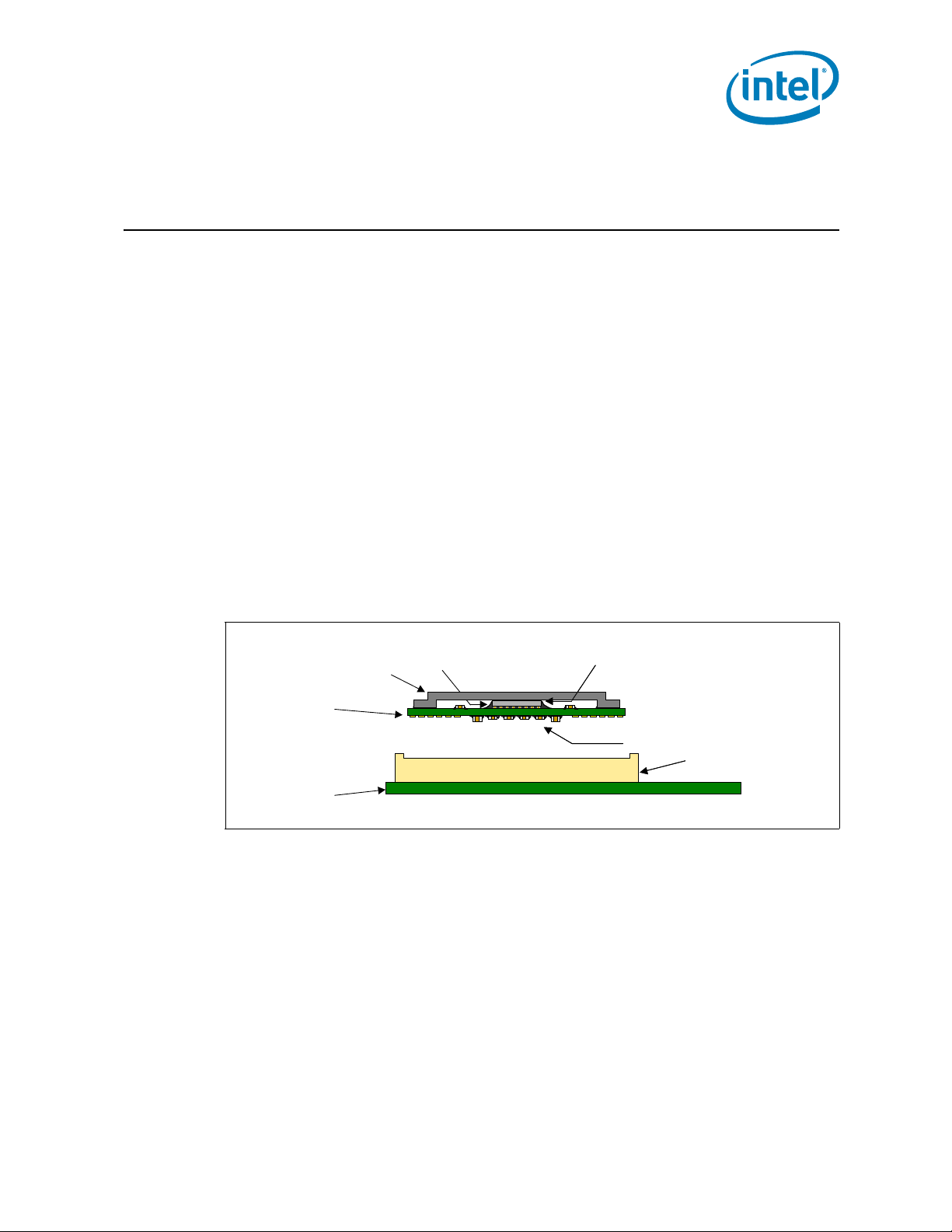
IHS
Substrate
System Board
Capacitors
Core (die)
TIM
LGA1155 Socket
2 Package Mechanical & Storage
Specifications
2.1 Package Mechanical Specifications
The processor is packaged in a Flip-Chip Land Grid Array package that interfaces with
the motherboard via the LGA1155 socket. The package consists of a processor
mounted on a substrate land-carrier. An integrated heat spreader (IHS) is attached to
the package substrate and core and serves as the mating surface for processor thermal
solutions, such as a heatsink. Figure 2-1 shows a sketch of the processor package
components and how they are assembled together. Refer to Chapter 3 and Chapter 4
for complete details on the LGA1155 socket.
The package components shown in Figure 2-1 include the following:
1. Integrated Heat Spreader (IHS)
2. Thermal Interface Material (TIM)
3. Processor core (die)
4. Package substrate
5. Capacitors
Figure 2-1. Processor Package Assembly Sketch
Note:
1. Socket and motherboard are included for reference and are not part of processor package.
2. For clarity the ILM not shown.
Thermal/Mechanical Specifications and Design Guidelines 13
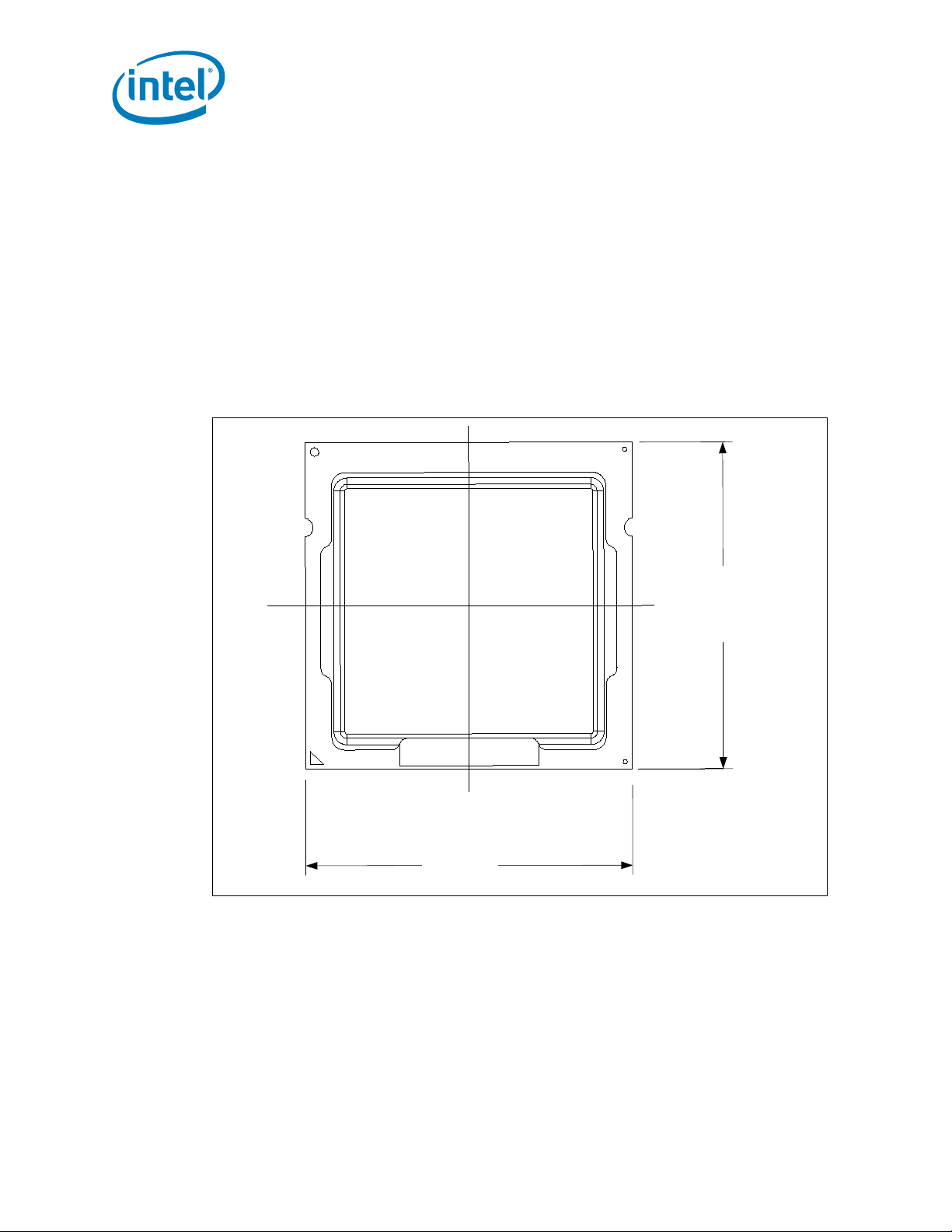
2.1.1 Package Mechanical Drawing
37.5
37.5
Figure 2-2 shows the basic package layout and dimensions. The detailed package
mechanical drawings are in Appendix D. The drawings include dimensions necessary to
design a thermal solution for the processor. These dimensions include:
1. Package reference with tolerances (total height, length, width, and so on)
2. IHS parallelism and tilt
3. Land dimensions
4. Top-side and back-side component keep-out dimensions
5. Reference datums
6. All drawing dimensions are in mm.
Figure 2-2. Package View
Package Mechanical & Storage Specifications
2.1.2 Processor Component Keep-Out Zones
The processor may contain components on the substrate that define component keepout zone requirements. A thermal and mechanical solution design must not intrude into
the required keep-out zones. Decoupling capacitors are typically mounted to either the
topside or land-side of the package substrate. See Figure B-3 and Figure B-4 for keepout zones. The location and quantity of package capacitors may change due to
manufacturing efficiencies but will remain within the component keep-in. This keep-in
zone includes solder paste and is a post reflow maximum height for the components.
14 Thermal/Mechanical Specifications and Design Guidelines

Package Mechanical & Storage Specifications
2.1.3 Package Loading Specifications
Ta b le 2 - 1 provides dynamic and static load specifications for the processor package.
These mechanical maximum load limits should not be exceeded during heatsink
assembly, shipping conditions, or standard use condition. Also, any mechanical system
or component testing should not exceed the maximum limits. The processor package
substrate should not be used as a mechanical reference or load-bearing surface for
.
Table 2-1. Processor Loading Specifications
thermal and mechanical solution.
Parameter Minimum Maximum Notes
Static Compressive Load - 600 N [135 lbf] 1, 2, 3
Dynamic Compressive Load - 712 N [160 lbf ] 1, 3, 4
Notes:
1. These specifications apply to uniform compressive loading in a direction normal to the processor IHS.
2. This is the maximum static force that can be applied by the heatsink and retention solution to maintain the
heatsink and processor interface.
3. These specifications are based on limited testing for design characterization. Loading limits are for the
package only and do not include the limits of the processor socket.
4. Dynamic loading is defined as an 50g shock load, 2X Dynamic Acceleration Factor with a 500g maximum
thermal solution.
2.1.4 Package Handling Guidelines
Ta b le 2 - 2 includes a list of guidelines on package handling in terms of recommended
maximum loading on the processor IHS relative to a fixed substrate. These package
handling loads may be experienced during heatsink removal.
Table 2-2. Package Handling Guidelines
Parameter Maximum Recommended Notes
Shear 311 N [70 lbf] 1, 4
Tensile 111 N [25 lbf] 2, 4
Torque 3.95 N-m [35 lbf-in] 3, 4
Notes:
1. A shear load is defined as a load applied to the IHS in a direction parallel to the IHS top surface.
2. A tensile load is defined as a pulling load applied to the IHS in a direction normal to the IHS surface.
3. A torque load is defined as a twisting load applied to the IHS in an axis of rotation normal to the IHS top
surface.
4. These guidelines are based on limited testing for design characterization.
2.1.5 Package Insertion Specifications
The processor can be inserted into and removed from an LGA1155 socket 15 times. The
socket should meet the LGA1155 socket requirements detailed in Chapter 5.
2.1.6 Processor Mass Specification
The typical mass of the processor is 21.5g (0.76 oz). This mass [weight] includes all
the components that are included in the package.
Thermal/Mechanical Specifications and Design Guidelines 15
2.1.7 Processor Materials
Sample (QDF):
GRP1LINE1: i{M}{C}YY
GRP1LINE2: INTEL CONFIDENTIAL
GRP1LINE3: QDF ES SPEED
GRP1LINE4: COUNTRY OF ORIGIN
GRP1LINE5: {FPO} {e4}
Production (SSPEC):
GRP1LINE1: i{M}{C}YY
GRP1LINE2: BRAND PROC#
GRP1LINE3: SSPEC SPEED
GRP1LINE4: COUNTRY OF ORIGIN
GRP1LINE5: {FPO} {e4}
Package Mechanical & Storage Specifications
Tab l e 2- 3 lists some of the package components and associated materials.
Table 2-3. Processor Materials
Component Material
Integrated Heat Spreader (IHS) Nickel Plated Copper
Substrate Fiber Reinforced Resin
Substrate Lands Gold Plated Copper
2.1.8 Processor Markings
Figure 2-3 shows the topside markings on the processor. This diagram is to aid in the
identification of the processor.
Figure 2-3. Processor Top-Side Markings
GRP1LINE1
GRP1LINE2
GRP1LINE3
GRP1LINE4
GRP1LINE5
S/N
16 Thermal/Mechanical Specifications and Design Guidelines
Package Mechanical & Storage Specifications
AY
AV
AT
AP
AM
AK
AH
AF
AD
AB
Y
V
T
P
M
K
H
F
D
B
AW
AU
AR
AN
AL
AJ
AG
AE
AC
AA
W
U
N
R
K
J
G
E
C
A
1 3 5 7 9 11 13 15 17 19 21 23 25 27 29 31
33 35 37 39
2 4 6 8 101214 1618202224 26283032
34 36 38 40
2.1.9 Processor Land Coordinates
.
Figure 2-4. Processor Package Lands Coordinates
Thermal/Mechanical Specifications and Design Guidelines 17
Figure 2-4 shows the bottom view of the processor package.

Package Mechanical & Storage Specifications
2.2 Processor Storage Specifications
Tab l e 2- 4 includes a list of the specifications for device storage in terms of maximum
and minimum temperatures and relative humidity. These conditions should not be
.
Table 2-4. Storage Conditions
exceeded in storage or transportation.
Parameter Description Min Max Notes
T
ABSOLUTE STORAGE
T
SUSTAINED STORAGE
RH
SUSTAINED STORAGE
TIME
SUSTAINED STORAGE
Notes:
1. Refers to a component device that is not assembled in a board or socket that is not to be electrically
connected to a voltage reference or I/O signals.
2. Specified temperatures are based on data collected. Exceptions for surface mount reflow are specified in by
applicable JEDEC standard Non-adherence may affect processor reliability.
3. T
ABSOLUTE STORAGE
moisture barrier bags or desiccant.
4. Intel branded board products are certified to meet the following temperature and humidity limits that are
given as an example only (Non-Operating Temperature Limit: -40 °C to 70 °C, Humidity: 50% to 90%,
non-condensing with a maximum wet bulb of 28 °C). Post board attach storage temperature limits are not
specified for non-Intel branded boards.
5. The JEDEC, J-JSTD-020 moisture level rating and associated handling practices apply to all moisture
sensitive devices removed from the moisture barrier bag.
6. Nominal temperature and humidity conditions and durations are given and tested within the constraints
imposed by T
The non-operating device storage temperature.
Damage (latent or otherwise) may occur when
subjected to for any length of time.
The ambient storage temperature limit (in
shipping media) for a sustained period of time.
The maximum device storage relative humidity
for a sustained period of time.
A prolonged or extended period of time; typically
associated with customer shelf life.
applies to the unassembled component only and does not apply to the shipping media,
SUSTAINED STORAGE
and customer shelf life in applicable intel box and bags.
-55 °C 125 °C 1, 2, 3
-5 °C 40 °C 4, 5
60% @ 24 °C 5, 6
0
Months6 Months
6
§
18 Thermal/Mechanical Specifications and Design Guidelines

LGA1155 Socket
3 LGA1155 Socket
This chapter describes a surface mount, LGA (Land Grid Array) socket intended for the
processors. The socket provides I/O, power and ground contacts. The socket contains
1155 contacts arrayed about a cavity in the center of the socket with lead-free solder
balls for surface mounting on the motherboard.
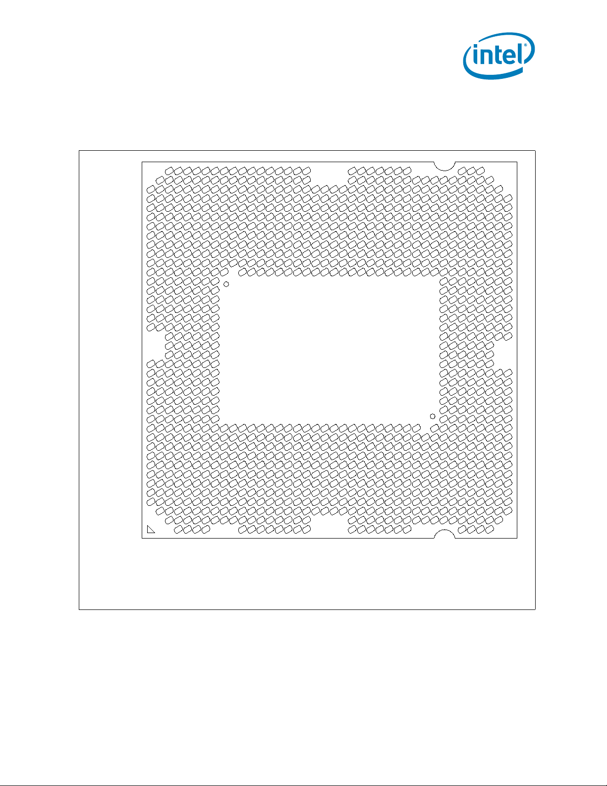
The contacts are arranged in two opposing L-shaped patterns within the grid array. The
grid array is 40 x 40 with 24 x 16 grid depopulation in the center of the array and
selective depopulation elsewhere.
The socket must be compatible with the package (processor) and the Independent
Loading Mechanism (ILM). The ILM design includes a back plate which is integral to
having a uniform load on the socket solder joints. Socket loading specifications are
listed in Chapter 5.
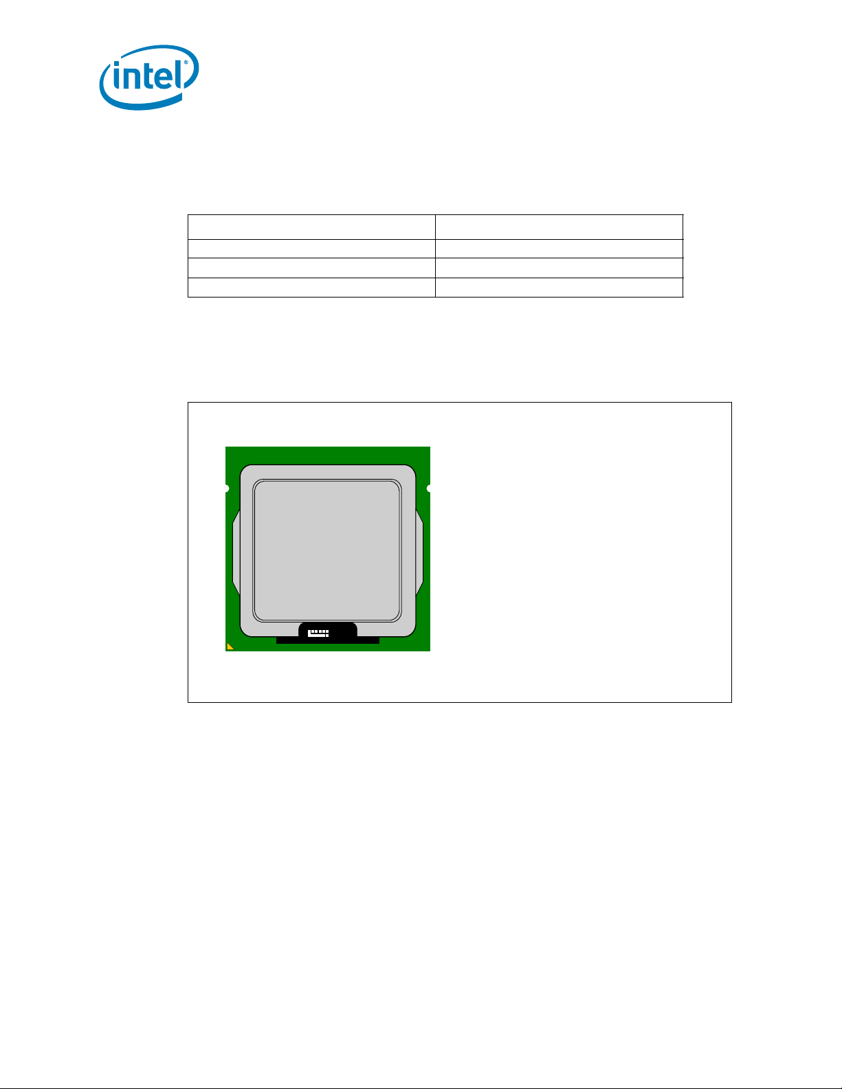
Figure 3-1. LGA1155 Socket with Pick and Place Cover
Thermal/Mechanical Specifications and Design Guidelines 19

Figure 3-2. LGA1155 Socket Contact Numbering (Top View of Socket)
A C E G J L N R U W AA AC AE AG AJ AL AN AR AU AW
B D F H K M P T V Y AB AD AF AH AK AM AP AT AV AY
1
3
7
5
9
11
15
13
17
19
23
21
25
27
29
2
8
4
6
10
16
12
14
18
24
20
22
26
28
30
15
11
13
17
23
19
21
25
31
27
29
33
39
35
37
32
14
12
16
18
22
20
24
26
30
28
34
38
36
40
LGA1155 Socket
3.1 Board Layout
The land pattern for the LGA1155 socket is 36 mils X 36 mils (X by Y) within each of the
two L-shaped sections. Note that there is no round-off (conversion) error between
20 Thermal/Mechanical Specifications and Design Guidelines
socket pitch (0.9144 mm) and board pitch (36 mil) as these values are equivalent. The
two L-sections are offset by 0.9144 mm (36 mil) in the x direction and 3.114 mm
(122.6 mil) in the y direction, see Figure 3-3. This was to achieve a common package
land to PCB land offset which ensures a single PCB layout for socket designs from the
multiple vendors.

LGA1155 Socket
A C E G J L N R U W AA AC AE AG AJ AL AN AR AU AW
B D F H K M P T V Y AB AD AF AH AK AM AP AT AV AY
1
3
7
5
9
11
15
13
17
19
23
21
25
27
29
2
8
4
6
10
16
12
14
18
24
20
22
26
28
30
32
15
11
14
12
13
16
17
23
19
18
22
20
21
24
25
31
27
26
30
28
29
33
39
35
34
38
36
37
40
B D F H K M P T V Y AB AD AF AH AK AM AP AT AV AY
A C E G J L N R U W AA AC AE AG AJ AL AN AR AU AW
122.6 mi l (3.1 144mm )
36mil (0.9144 mm )
Figure 3-3. LGA1155 Socket Land Pattern (Top View of Board)
Thermal/Mechanical Specifications and Design Guidelines 21
LGA1155 Socket
Load plate
Frame
Load Lever
Back Plate
Shoulder
Screw
Load plate
Frame
Load Lever
Back Plate
Shoulder
Screw
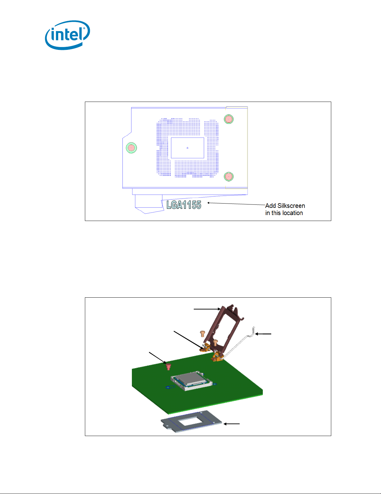
3.1.1 Suggested Silkscreen Marking for Socket Identification
Intel is recommending that customers mark the socket name approximately where
shown in Figure 3-4.
Figure 3-4. Suggested Board Marking
3.2 Attachment to Motherboard
The socket is attached to the motherboard by 1155 solder balls. There are no additional
external methods (that is, screw, extra solder, adhesive, and so on) to attach the
socket.
As indicated in Figure 3-1, the Independent Loading Mechanism (ILM) is not present
during the attach (reflow) process.
Figure 3-5. Attachment to Motherboard
22 Thermal/Mechanical Specifications and Design Guidelines

LGA1155 Socket
3.3 Socket Components
The socket has two main components, the socket body and Pick and Place (PnP) cover,
and is delivered as a single integral assembly. Refer to Appendix C for detailed
drawings.
3.3.1 Socket Body Housing
The housing material is thermoplastic or equivalent with UL 94 V-0 flame rating capable
of withstanding 260 °C for 40 seconds which is compatible with typical reflow/rework
profiles. The socket coefficient of thermal expansion (in the XY plane), and creep
properties, must be such that the integrity of the socket is maintained for the
conditions listed in Chapter 5.
The color of the housing will be dark as compared to the solder balls to provide the
contrast needed for pick and place vision systems.
3.3.2 Solder Balls
A total of 1155 solder balls corresponding to the contacts are on the bottom of the
socket for surface mounting with the motherboard. The socket solder ball has the
following characteristics:
• Lead free SAC (SnAgCu) 305 solder alloy with a silver (Ag) content between 3%
and 4% and a melting temperature of approximately 217 °C. The alloy is
compatible with immersion silver (ImAg) and Organic Solderability Protectant
(OSP) motherboard surface finishes and a SAC alloy solder paste.
• Solder ball diameter 0.6 mm ± 0.02 mm, before attaching to the socket lead.
The co-planarity (profile) and true position requirements are defined in Appendix C.
3.3.3 Contacts
Base material for the contacts is high strength copper alloy.
For the area on socket contacts where processor lands will mate, there is a 0.381 m
[15 inches] minimum gold plating over 1.27 m [50 inches] minimum nickel
underplate.
No contamination by solder in the contact area is allowed during solder reflow.
3.3.4 Pick and Place Cover
The cover provides a planar surface for vacuum pick up used to place components in
the Surface Mount Technology (SMT) manufacturing line. The cover remains on the
socket during reflow to help prevent contamination during reflow. The cover can
withstand 260 °C for 40 seconds (typical reflow/rework profile) and the conditions
listed in Chapter 5 without degrading.
As indicated in Figure 3-6, the cover remains on the socket during ILM installation, and
should remain on whenever possible to help prevent damage to the socket contacts.
Thermal/Mechanical Specifications and Design Guidelines 23

Cover retention must be sufficient to support the socket weight during lifting,
Pick & Place Cover
Pin 1
ILM Installation
Pick & Place Cover
Pin 1
ILM Installation
translation, and placement (board manufacturing), and during board and system
shipping and handling. PnP Cover should only be removed with tools, to prevent the
cover from falling into the contacts.
The socket vendors have a common interface on the socket body where the PnP cover
attaches to the socket body. This should allow the PnP covers to be compatible between
socket suppliers.
As indicated in Figure 3-6, a Pin1 indicator on the cover provides a visual reference for
proper orientation with the socket.
Figure 3-6. Pick and Place Cover
LGA1155 Socket
3.4 Package Installation / Removal
24 Thermal/Mechanical Specifications and Design Guidelines
As indicated in Figure 3-7, access is provided to facilitate manual installation and
removal of the package.
To assist in package orientation and alignment with the socket:
• The package Pin1 triangle and the socket Pin1 chamfer provide visual reference for
proper orientation.
• The package substrate has orientation notches along two opposing edges of the
package, offset from the centerline. The socket has two corresponding orientation
posts to physically prevent mis-orientation of the package. These orientation
features also provide initial rough alignment of package to socket.
• The socket has alignment walls at the four corners to provide final alignment of the
package.

LGA1155 Socket
Pin 1
Chamfer
Package
Pin 1
Indicator
Alignment
Post
(2 Places)
Finger/Tool
Access
(2 Pla ces)
Orientation
Notch
(2 Place s)
.
Figure 3-7. Package Installation / Removal Features
3.4.1 Socket Standoffs and Package Seating Plane
Standoffs on the bottom of the socket base establish the minimum socket height after
solder reflow and are specified in Appendix C.
Similarly, a seating plane on the topside of the socket establishes the minimum
package height. See Section 5.2 for the calculated IHS height above the motherboard.
3.5 Durability
The socket must withstand 20 cycles of processor insertion and removal. The max
chain contact resistance from Tab l e 5 - 4 must be met when mated in the 1st and 20th
cycles.
The socket Pick and Place cover must withstand 15 cycles of insertion and removal.
3.6 Markings
There are three markings on the socket:
• LGA1155: Font type is Helvetica Bold - minimum 6 point (2.125 mm). This mark
will also appear on the pick and place cap.
• Manufacturer's insignia (font size at supplier's discretion).
• Lot identification code (allows traceability of manufacturing date and location).
Thermal/Mechanical Specifications and Design Guidelines 25

All markings must withstand 260 °C for 40 seconds (typical reflow/rework profile)
without degrading, and must be visible after the socket is mounted on the
motherboard.
LGA1155 and the manufacturer's insignia are molded or laser marked on the side wall.
3.7 Component Insertion Forces
Any actuation must meet or exceed SEMI S8-95 Safety Guidelines for Ergonomics/
Human Factors Engineering of Semiconductor Manufacturing Equipment, example Table
R2-7 (Maximum Grip Forces). The socket must be designed so that it requires no force
to insert the package into the socket.
3.8 Socket Size
Socket information needed for motherboard design is given in Appendix C.
This information should be used in conjunction with the reference motherboard keepout drawings provided in Appendix B to ensure compatibility with the reference thermal
mechanical components.
LGA1155 Socket
§
26 Thermal/Mechanical Specifications and Design Guidelines

Independent Loading Mechanism (ILM)
4 Independent Loading
Mechanism (ILM)
The ILM has two critical functions: deliver the force to seat the processor onto the
socket contacts and distribute the resulting compressive load evenly through the socket
solder joints.
The mechanical design of the ILM is integral to the overall functionality of the LGA1155
socket. Intel performs detailed studies on integration of processor package, socket and
ILM as a system. These studies directly impact the design of the ILM. The Intel
reference ILM will be “build to print” from Intel controlled drawings. Intel recommends
using the Intel Reference ILM. Custom non-Intel ILM designs do not benefit from Intel's
detailed studies and may not incorporate critical design parameters.
Note: There is a single ILM design for the LGA1155 socket and LGA1156 socket.
4.1 Design Concept
The ILM consists of two assemblies that will be procured as a set from the enabled
vendors. These two components are ILM assembly and back plate. To secure the two
assemblies, two types of fasteners are required a pair (2) of standard 6-32 thread
screws and a custom 6-32 thread shoulder screw. The reference design incorporates a
T-20 Torx* head fastener. The Torx* head fastener was chosen to ensure end users do
not inadvertently remove the ILM assembly and for consistency with the LGA1366
socket ILM. The Torx* head fastener is also less susceptible to driver slippage. Once
assembled the ILM is not required to be removed to install / remove the motherboard
from a chassis.
4.1.1 ILM Assembly Design Overview
The ILM assembly consists of 4 major pieces: ILM cover, load lever, load plate and the
hinge frame assembly.
All of the pieces in the ILM assembly except the hinge frame and the screws used to
attach the back plate are fabricated from stainless steel. The hinge frame is plated. The
frame provides the hinge locations for the load lever and load plate. An insulator is preapplied to the bottom surface of the hinge frame.
The ILM assembly design ensures that once assembled to the back plate the only
features touching the board are the shoulder screw and the insulated hinge frame
assembly. The nominal gap of the load plate to the board is ~1 mm.
When closed the load plate applies two point loads onto the IHS at the “dimpled”
features shown in Figure 4-1. The reaction force from closing the load plate is
transmitted to the hinge frame assembly and through the fasteners to the back plate.
Some of the load is passed through the socket body to the board inducing a slight
compression on the solder joints.
A pin 1 indicator will be marked on the ILM assembly.
Thermal/Mechanical Specifications and Design Guidelines 27

Figure 4-1. ILM Assembly with Installed Processor
Fasteners
Load
Lever
Load
Plate
Hinge /
Frame
Assy
Shoulder Screw
Pin 1 Indicator
Fasteners
Load
Lever
Load
Plate
Hinge /
Frame
Assy
Shoulder Screw
Pin 1 Indicator
Independent Loading Mechanism (ILM)
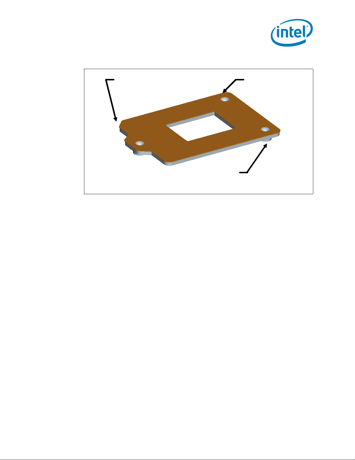
4.1.2 ILM Back Plate Design Overview
The back plate is a flat steel back plate with pierced and extruded features for ILM
attach. A clearance hole is located at the center of the plate to allow access to test
points and backside capacitors if required. An insulator is pre-applied. A notch is placed
in one corner to assist in orienting the back plate during assembly.
Caution: Intel does NOT recommend using the server back plate for high-volume desktop
applications at this time as the server back plate test conditions cover a limited
envelope. Back plates and screws are similar in appearance. To prevent mixing,
different levels of differentiation between server and desktop back plate and screws
have been implemented.
For ILM back plate, three levels of differentiation have been implemented:
• Unique part numbers, please refer to part numbers listed in Appendix A.
• Desktop ILM back plate to use black lettering for marking versus server ILM back
plate to use yellow lettering for marking.
• Desktop ILM back plate using marking “115XDBP” versus server ILM back plate
using marking “115XSBP”.
Note: When reworking a BGA component or the socket that the heatsink, battery, ILM and
ILM Back Plate are removed prior to rework. The ILM back plate should also be
removed when reworking through hole mounted components in a mini-wave or solder
pot). The maximum temperature for the pre-applied insulator on the ILM is
approximately 106 °C.
28 Thermal/Mechanical Specifications and Design Guidelines
Independent Loading Mechanism (ILM)
Die Cut
Insulator
Pierced & Extruded
Thread Features
Assembly
Orientation
Feature
Die Cut
Insulator
Pierced & Extruded
Thread Features
Assembly
Orientation
Feature
Figure 4-2. Back Plate
4.1.3 Shoulder Screw and Fasteners Design Overview
Note: The screws for Server ILM are different from Desktop design. The length of Server ILM
Note: Unique part numbers, please refer to Appendix A.
Note: The reference design incorporates a T-20 Torx* head fastener. The Torx* head fastener
The shoulder screw is fabricated from carbonized steel rod. The shoulder height and
diameter are integral to the mechanical performance of the ILM. The diameter provides
alignment of the load plate. The height of the shoulder ensures the proper loading of
the IHS to seat the processor on the socket contacts. The design assumes the shoulder
screw has a minimum yield strength of 235 MPa.
A dimensioned drawing of the shoulder screw is available for local sourcing of this
component. Please refer to Figure B-13 for the custom 6-32 thread shoulder screw
drawing.
The standard fasteners can be sourced locally. The design assumes this fastener has a
minimum yield strength of 235 MPa. Please refer to Figure B-14 for the standard 6-32
thread fasteners drawing.
screws are shorter than the Desktop screw length to satisfy Server secondary-side
clearance limitation.
was chosen to ensure end users do not inadvertently remove the ILM assembly and for
consistency with the LGA1366 socket ILM.
Thermal/Mechanical Specifications and Design Guidelines 29

Figure 4-3. Shoulder Screw
Shoulder
6-32 thread
Cap
Independent Loading Mechanism (ILM)
4.2 Assembly of ILM to a Motherboard
The ILM design allows a bottoms up assembly of the components to the board. See
Figure 4-4 for step by step assembly sequence.
1. Place the back plate in a fixture. The motherboard is aligned with the fixture.
2. Install the shoulder screw in the single hole near Pin 1 of the socket. Torque to a
minimum and recommended 8 inch-pounds, but not to exceed 10 inch-pounds.
3. Align and place the ILM assembly over the socket.
4. Install two (2) 6-32 fasteners. Torque to a minimum and recommended 8 inchpounds, but not to exceed 10 inch-pounds.
The thread length of the shoulder screw accommodates a nominal board thicknesses of
0.062”.
30 Thermal/Mechanical Specifications and Design Guidelines
 Loading...