

Intel BOXD850MVSE, Desktop Board D850MD, D850MDL - P4 Socket 478 ATX Motherboard, Desktop Board D850MV Product Manual
Intel® Desktop Boards
D850MD and D850MV
Product Guide
Order Number: A57861-001

Revision History
Revision Revision History Date
-001 First release of the Intel® Desktop Boards D850MD and D850MV
Product Guide.
If an FCC declaration of conformity marking is present on the board, the following statement applies:
FCC Declaration of Conformity
This device complies with Part 15 of the FCC Rules. Operation is subject to the following two conditions: (1) this device
may not cause harmful interference, and (2) this device must accept any interference received, including interference that
may cause undesired operation.
For questions related to the EMC performance of this product, contact:
Intel Corporation
5200 N.E. Elam Young Parkway
Hillsboro, OR 97124
1-800-628-8686
This equipment has been tested and found to comply with the limits for a Class B digital device, pursuant to Part 15 of the
FCC Rules. These limits are designed to provide reasonable protection against harmful interference in a residential
installation. This equipment generates, uses, and can radiate radio frequency energy and, if not installed and used in
accordance with the instructions, may cause harmful interference to radio communications. However, there is no guarantee
that interference will not occur in a particular installation. If this equipment does cause harmful interference to radio or
television reception, which can be determined by turning the equipment off and on, the user is encouraged to try to correct
the interference by one or more of the following measures:
• Reorient or relocate the receiving antenna.
• Increase the separation between the equipment and the receiver.
• Connect the equipment to an outlet on a circuit other than the one to which the receiver is connected.
• Consult the dealer or an experienced radio/TV technician for help.
Canadian Department of Communications Compliance Statement
This digital apparatus does not exceed the Class B limits for radio noise emissions from digital apparatus set out in the
Radio Interference Regulations of the Canadian Department of Communications.
Le présent appareil numerique német pas de bruits radioélectriques dépassant les limites applicables aux appareils
numériques de la classe B prescrites dans le Réglement sur le broullage radioélectrique édicté par le ministére des
Communications du Canada.
Disclaimer
INFORMATION IN THIS DOCUMENT IS PROVIDED IN CONNECTION WITH INTEL
PROVIDED IN INTEL'S TERMS AND CONDITIONS OF SALE FOR SUCH PRODUCTS, INTEL ASSUMES NO LIABILITY
WHATSOEVER, AND INTEL DISCLAIMS ANY EXPRESS OR IMPLIED WARRANTY, RELATING TO SALE AND/OR USE
OF INTEL PRODUCTS INCLUDING LIABILITY OR WARRANTIES RELATING TO FITNESS FOR A PARTICULAR
PURPOSE, MERCHANTABILITY, OR INFRINGEMENT OF ANY PATENT, COPYRIGHT, OR OTHER INTELLECTUAL
PROPERTY RIGHT.
Intel Corporation may have patents or pending patent applications, trademarks, copyrights, or other intellectual property
rights that relate to the presented subject matter. The furnishing of documents and other materials and information does
not provide any license, express or implied, by estoppel or otherwise, to any such patents, trademarks, copyrights, or other
intellectual property rights.
Intel products are not designed, intended or authorized for use in any medical, life saving, or life sustaining applications or
for any other application in which the failure of the Intel product could create a situation where personal injury or death may
occur.
Intel may make changes to specifications, product descriptions, and plans at any time, without notice.
The D850MD and D850MV desktop boards may contain design defects or errors known as errata which may cause the product to
deviate from published specifications. Current characterized errata are available on request.
Contact your local Intel sales office or your distributor to obtain the latest specifications and before placing your product order.
Copies of documents which have an ordering number and are referenced in this document, or other Intel literature, may be
obtained from Intel Corporation by going to the World Wide Web site at:
Intel and Pentium are registered trademarks of Intel Corporation or it subsidiaries in the United States and other countries.
†
Other names and brands may be claimed as the property of others.
Copyright © 2001, Intel Corporation. All Rights Reserved.
http://www.intel.com/ or by calling: 1-800-548-4725.
PRODUCTS. . EXCEPT AS
July 2001

Contents
1 Desktop Board Features
Board Components .............................................................................................................. 9
Processor........................................................................................................................... 11
Main Memory .....................................................................................................................12
®
850 Chipset .............................................................................................................. 12
Intel
®
82850 Memory Controller Hub (MCH).............................................................. 12
Intel
®
82801BA I/O Controller Hub (ICH2) ................................................................. 13
Intel
Firmware Hub (FWH)................................................................................................. 13
Input/Output (I/O) Controller............................................................................................... 13
Real-Time Clock.................................................................................................................13
USB Support ...................................................................................................................... 14
PCI Enhanced IDE Interface .............................................................................................. 14
Expansion Slots.................................................................................................................. 14
AGP Connector ......................................................................................................... 15
Communication and Networking Riser (CNR) (Optional) ........................................... 15
Audio Subsystem ............................................................................................................... 15
BIOS .................................................................................................................................. 15
PCI Auto Configuration.............................................................................................. 15
IDE Auto Configuration.............................................................................................. 16
Security Passwords ................................................................................................... 16
LAN Subsystem (Optional)................................................................................................. 17
LAN Subsystem Software.......................................................................................... 17
RJ-45 LAN Connector LEDs...................................................................................... 17
Speaker.............................................................................................................................. 17
Battery................................................................................................................................ 17
Power Management Features ............................................................................................ 18
Instantly Available Technology .................................................................................. 18
Resume on Ring........................................................................................................ 20
2 Installing and Replacing Desktop Board Components
Before You Begin ............................................................................................................... 21
Installing the I/O Shield.......................................................................................................22
Installing and Removing the Desktop Board....................................................................... 23
Installing and Removing a Processor ................................................................................. 25
Installing the Processor Fan Heatsink Retention Mechanism Base ........................... 25
Installing a Processor ................................................................................................ 27
Installing the Processor Fan Heatsink........................................................................ 27
Connecting the Processor Fan Cable ........................................................................ 28
Removing a Processor .............................................................................................. 28
Installing and Removing Memory ....................................................................................... 29
Installing Memory ...................................................................................................... 29
Removing Memory .................................................................................................... 31
iii

Intel Desktop Boards D850MD and D850MV Product Guide
Installing and Removing an AGP Card Retention Mechanism and Card ............................ 32
Installing the AGP Card Retention Mechanism.......................................................... 32
Installing an AGP Card .............................................................................................. 34
Removing the AGP Card from the Retention Mechanism .......................................... 34
Removing the AGP Card Retention Mechanism ........................................................ 35
Connecting the IDE Cable.................................................................................................. 36
Setting the BIOS Configuration Jumper.............................................................................. 37
Clearing Passwords............................................................................................................ 38
Replacing the Battery ......................................................................................................... 39
3 Updating the BIOS
Updating the BIOS with the Intel® Express BIOS Update Utility ......................................... 43
®
Updating the BIOS with the Intel
Flash Memory Update Utility ......................................... 43
Obtaining the BIOS Update File................................................................................. 43
Updating the BIOS..................................................................................................... 44
Recovering the BIOS................................................................................................. 44
4 Using the Setup Program
Maintenance Menu............................................................................................................. 48
Extended Configuration Submenu............................................................................. 49
Main Menu ......................................................................................................................... 50
Advanced Menu ................................................................................................................. 51
PCI Configuration Submenu...................................................................................... 52
Boot Configuration Submenu..................................................................................... 53
Peripheral Configuration Submenu............................................................................ 54
IDE Configuration Submenu...................................................................................... 56
Primary/Secondary IDE Master/Slave Submenus...................................................... 57
Diskette Configuration Submenu ............................................................................... 58
Event Log Configuration Submenu............................................................................ 59
Video Configuration Submenu................................................................................... 59
Security Menu .................................................................................................................... 60
Power Menu....................................................................................................................... 61
APM Submenu .......................................................................................................... 62
ACPI Submenu.......................................................................................................... 62
Boot Menu.......................................................................................................................... 63
Boot Device Priority ................................................................................................... 63
Exit Menu ........................................................................................................................... 64
5 Technical Reference
Board Connectors .............................................................................................................. 65
Back Panel Connectors ............................................................................................. 66
Midboard Connectors ................................................................................................ 67
Audio Connectors.............................................................................................. 67
Power and Hardware Connectors ..................................................................... 68
Add-In Card and Peripheral Interface Connectors............................................. 70
Front Panel Connectors............................................................................................. 72
iv

Desktop Board Resources.................................................................................................. 73
Memory Map ............................................................................................................. 73
DMA Channels .......................................................................................................... 73
I/O Map ..................................................................................................................... 74
Interrupts ................................................................................................................... 76
A Error Messages and Indicators
BIOS Beep Codes.............................................................................................................. 77
BIOS Error Messages ........................................................................................................ 78
B Regulatory Compliance
Safety Regulations ............................................................................................................. 81
EMC Regulations ............................................................................................................... 81
Product Certification Markings............................................................................................ 82
Installation Precautions ...................................................................................................... 83
Installation Instructions.......................................................................................................83
Ensure Electromagnetic Compatibility (EMC) Compliance......................................... 83
Chassis and Component Certifications ...................................................................... 84
Prevent Power Supply Overload................................................................................ 84
Place Battery Marking................................................................................................ 84
Use Only for Intended Applications............................................................................ 85
Contents
Figures
1. D850MD Board Components ......................................................................................... 9
2. D850MV Board Components ....................................................................................... 10
3. Location of Standby Power Indicator............................................................................ 19
4. Installing the I/O Shield................................................................................................ 22
5. D850MD Board Mounting Screw Holes........................................................................ 23
6. D850MV Board Mounting Screw Holes........................................................................ 24
7. Location of the Processor Fan Heatsink Base Mounting Holes.................................... 25
8. Installing the Processor Fan Heatsink RM Base to the Board ...................................... 26
9. Installing a Processor................................................................................................... 27
10. Connecting the Processor Fan Cable to the Processor Fan Connector ....................... 28
11. RDRAM and CRIMM Installation.................................................................................. 29
12. RIMM Installation ......................................................................................................... 30
13. Installing a Memory Module ......................................................................................... 31
14. AGP Card with a Retention Notch................................................................................ 32
15. Installing the AGP Card Retention Mechanism ............................................................ 33
16. Removing the AGP Card.............................................................................................. 34
17. Removing the AGP Card Retention Mechanism .......................................................... 35
18. Connecting the IDE Cable............................................................................................ 36
19. Location of the BIOS Configuration Jumper................................................................. 37
20. Removing the Battery .................................................................................................. 41
21. Back Panel Connectors................................................................................................ 66
22. Audio Connectors ........................................................................................................ 67
23. D850MD Board Power and Hardware Control Connectors .......................................... 68
24. D850MV Board Power and Hardware Control Connectors........................................... 69
25. D850MD Board Add-in Card and Peripheral Interface Connectors .............................. 70
v

Intel Desktop Boards D850MD and D850MV Product Guide
26. D850MV Board Add-in Card and Peripheral Interface Connectors............................... 71
27. Front Panel Connectors ............................................................................................... 72
Tables
1. Feature Summary.......................................................................................................... 7
2. Processors Supported by the Desktop Board .............................................................. 11
3. RJ-45 LAN Connector LEDs ........................................................................................ 17
4. Standby Current Requirements.................................................................................... 20
5. Jumper Settings for the BIOS Setup Program Modes (J9H2) ...................................... 37
6. BIOS Setup Program Menu Bar................................................................................... 47
7. BIOS Setup Program Function Keys............................................................................ 48
8. Maintenance Menu ...................................................................................................... 48
9. Extended Configuration Submenu ............................................................................... 49
10. Main Menu................................................................................................................... 50
11. Advanced Menu........................................................................................................... 51
12. PCI Configuration Submenu ........................................................................................ 52
13. Boot Configuration Submenu ....................................................................................... 53
14. Peripheral Configuration Submenu .............................................................................. 54
15. IDE Configuration Submenu ........................................................................................ 56
16. Primary/Secondary IDE Master/Slave Submenus........................................................ 57
17. Diskette Configuration Submenu.................................................................................. 58
18. Event Log Configuration Submenu .............................................................................. 59
19. Video Configuration Submenu ..................................................................................... 59
20. Security Menu.............................................................................................................. 60
21. Power Menu................................................................................................................. 61
22. APM Submenu............................................................................................................. 62
23. ACPI Submenu ............................................................................................................ 62
24. Boot Menu ................................................................................................................... 63
25. Boot Device Priority ..................................................................................................... 63
26. Exit Menu..................................................................................................................... 64
27. System Memory Map................................................................................................... 73
28. DMA Channels............................................................................................................. 73
29. I/O Map........................................................................................................................ 74
30. Interrupts ..................................................................................................................... 76
31. Beep Codes................................................................................................................. 77
32. BIOS Error Messages.................................................................................................. 78
33. Safety Regulations....................................................................................................... 81
34. EMC Regulations......................................................................................................... 81
vi

1 Desktop Board Features
NOTE
✏
The D850MD board layout was used for illustrations unless otherwise noted.
Table 1 describes the major features of the D850MD and D850MV boards.
Table 1. Feature Summary
Form Factors
Processor
Memory
Chipset
I/O Control
LAN
Graphics
Audio
Peripheral
Interfaces
Expansion
Capabilities
• microATX at 9.6 inches by 9.6 inches (D850MD board)
• ATX at 9.6 inches by 12 inches (D850MV board)
®
• Support for an Intel
• 400 MHz system data bus
• Four 168-pin Direct Rambus† RIMM† sockets
• Support for up to 2 GB of system memory
®
Intel
850 chipset, consisting of:
• Intel
• Intel
• 4 Mbit Firmware Hub (FWH)
SMSC LPC47M142 I/O controller
Optional Intel
RJ-45 connector
AGP connector supporting 1.5 V 4X or 2X AGP cards
Analog Devices Inc. AD1885 analog codec (AC ’97) featuring SoundMAX
software support
• Up to seven Universal Serial Bus (USB) ports
• Two IDE interfaces with Ultra DMA-33 and ATA-66/100 support
• One floppy drive interface
• One parallel port
• Two serial ports
• PS/2
D850MD board:
• Three PCI bus add-in card connectors
• One AGP connector
• One optional CNR connector (slot shared with PCI bus connector 3)
D850MV board:
• Five PCI bus add-in card connectors
• One AGP connector
• One optional CNR connector (slot shared with PCI bus connector 5)
®
82850 Memory Controller Hub (MCH) with Accelerated Hub Architecture
(AHA) bus
®
82801BA I/O Controller Hub (ICH2) with AHA bus
®
82562ET 10/100 Mbit/sec Platform LAN Connect (PLC) device and
Four ports routed to the back panel
Two ports routed to the front panel USB connector
One port routed to the optional CNR
†
keyboard and mouse ports
Pentium® 4 processor in an mPGA-478 socket
†
with SPX
†
continued
7

Intel Desktop Boards D850MD and D850MV Product Guide
Table 1. Feature Summary (continued)
BIOS
Power
Management
Management
Features
Instantly
Available PC
Other
Features
• Intel/AMI BIOS
• 4 Mbit symmetrical flash memory
• Support for SMBIOS
• Support for Advanced Configuration and Power Interface (ACPI 1.0)
• Support for Advanced Power Management (APM 1.2)
• Support for Plug and Play (PnP)
Hardware monitor with
• Two fan sensing inputs used to monitor fan activity
• Remote diode temperature sensing
• Voltage sensing to detect out of range values
• Support for PCI Local Bus Specification Revision 2.2
• Suspend to RAM (STR) support
• Wake on USB, PCI, CNR, RS-232, PS/2, LAN, and front panel
• SCSI hard drive activity LED connector for the front panel
• Speaker
NOTE
✏
For information about Intel® desktop boards, including technical product specifications, BIOS
updates, and device drivers, go to the Intel World Wide Web site at:
http://support.intel.com/support/motherboards/desktop
8
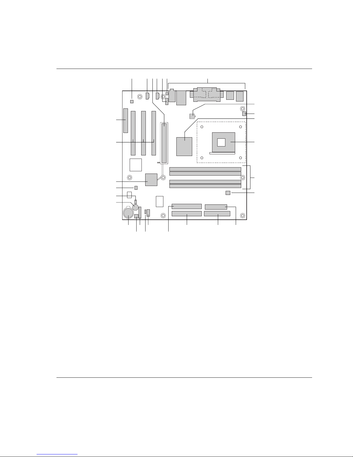
Board Components
Figure 1 shows the location of the major components on the D850MD board.
E
F
BB
C
B DA
G
Desktop Board Features
H
I
J
AA
Z
Y
X
W
R
U S
A ADI AD1885 audio codec P Primary IDE connector
B Auxiliary line-in connector (ATAPI) Q Secondary IDE connector
C AGP connector R Front panel USB connector
D CD-ROM connector (ATAPI) S Alternate power/sleep LED connector
E Front panel audio connector T Front panel connector
F Chassis intrusion connector U Chassis fan connector (fan 2)
G Back panel connectors V Battery
H ATX12V processor core voltage connector W Speaker
I Processor fan connector (CPU fan)
(tachometer input)
J Intel 82850 Memory Controller Hub (MCH) Y SCSI hard drive activity LED connector
K Processor socket Z Intel 82801BA I/O Controller Hub (ICH2)
L RIMM sockets AA PCI bus add-in card connectors
M RIMM fan connector (fan 1) BB Communication and Networking Riser (CNR)
N Power connector (optional)
O Floppy drive connector
Q
X BIOS configuration jumper
OP
(tachometer input)
NV T
K
L
M
OM11828
Figure 1. D850MD Board Components
9
Intel Desktop Boards D850MD and D850MV Product Guide
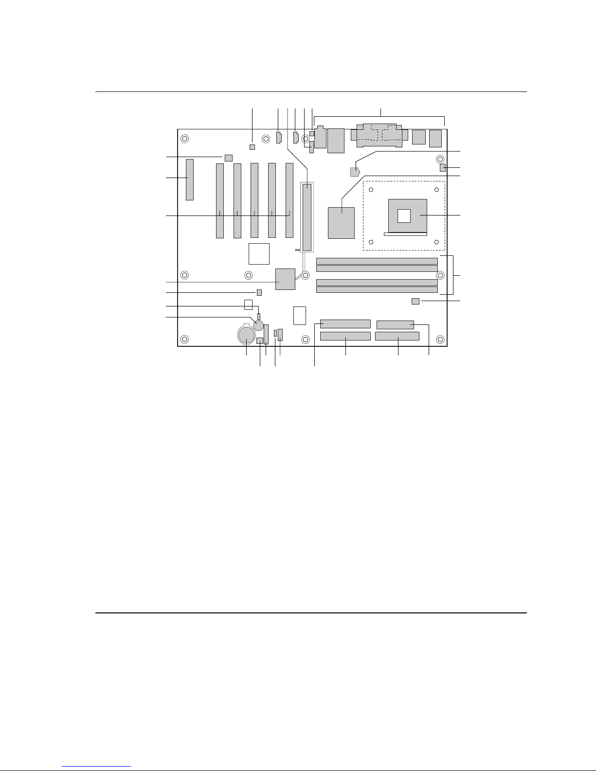
Figure 2 shows the location of the major components on the D850MV board.
E
F
C
B DA
G
CC
H
I
BB
AA
Z
J
K
L
Y
X
M
W
U S
R
OP
Q
NV T
OM12073
A ADI AD1885 audio codec P Primary IDE connector
B Auxiliary line-in connector (ATAPI) Q Secondary IDE connector
C AGP connector R Front panel USB connector
D CD-ROM connector (ATAPI) S Alternate power/sleep LED connector
E Front panel audio connector T Front panel connector
F Chassis intrusion connector U Chassis fan connector (fan 2)
(tachometer input)
G Back panel connectors V Battery
H ATX12V processor core voltage connector W Speaker
I Processor fan connector (CPU fan)
X BIOS configuration jumper
(tachometer input)
J Intel 82850 Memory Controller Hub (MCH) Y SCSI hard drive activity LED connector
K Processor socket Z Intel 82801BA I/O Controller Hub (ICH2)
L RIMM sockets AA PCI bus add-in card connectors
M RIMM fan connector (fan 1) BB Communication and Networking Riser (CNR)
N Power connector (optional)
O Floppy drive connector CC Chassis fan connector (fan 3)
10
Figure 2. D850MV Board Components

Desktop Board Features
Processor
CAUTION
Failure to use an ATX12V power supply, or not connecting the additional power supply lead to the
D850MD or D850MV boards may result in damage to the desktop board and/or power supply.
The board supports a single Intel Pentium 4 processor. Processors are not included with the board
and must be purchased separately.
The processor connects to the board through the mPGA 478-pin socket. The Pentium 4 processor
may be removed and replaced to accommodate supported higher speed processors.
For instructions on how to install a processor, see Chapter 2 on page 21.
The board supports the processors listed in Table 2.
Table 2. Processors Supported by the Desktop Board
Type
Intel Pentium 4 processor
in a mPGA-478 package
Designation
1.4, 1.5, 1.6, 1.7, and
1.8 GHz
System Bus Frequency L2 Cache Size
400 MHz 256 KB
For the latest information on processor support for the D850MD and D850MV boards, refer to the
Intel desktop board World Wide Web site at:
http://support.intel.com/support/motherboards/desktop
For instructions on installing or upgrading the processor, see Chapter 2 on page 21.
The D850MD and D850MV boards require an ATX12V compliant power supply to function
according to desktop board specifications. Both boards have two ATX12V compliant power
supply connectors that are needed to provide extra power to the Intel 850 chipset and Pentium 4
processor.
Items B and E in Figure 23 on page 68 and items C and F in Figure 24 on page 69 show the two
power connector locations.
11

Intel Desktop Boards D850MD and D850MV Product Guide
Main Memory
The board has four 2.5 V memory module sockets that support RIMMs containing Direct Rambus
DRAM (RDRAM) devices.
The board supports the following memory features:
• Maximum of 32 RDRAM devices per channel
• 128 MB (minimum) to 2 GB (maximum) onboard capacity utilizing 128/144 Mbit or
256/288 Mbit technology
• Single- or double-sided RIMM modules
• PC600 or PC800 compliant RDRAM
• Serial Presence Detect (SPD) memory only
NOTE
✏
For information about vendors that support these memory requirements, refer to the D850MD or
D850MV link on this Intel World Wide Web site:
http://support.intel.com/support/motherboards/desktop
For information about installing memory, see Chapter 2 on page 21.
Intel® 850 Chipset
The Intel 850 chipset consists of the following devices:
• Intel 82850 Memory Controller Hub (MCH) with AHA bus
• Intel 82801BA I/O Controller Hub (ICH2) with AHA bus
• Firmware Hub (FWH)
Intel® 82850 Memory Controller Hub (MCH)
The MCH has these features:
• Integrated dual Direct Rambus technology memory channel
• Support for 128 MB to 2 GB main system memory
• Auto-detection of RDRAM memory
• Support for a single AGP device
12

Desktop Board Features
Intel® 82801BA I/O Controller Hub (ICH2)
The ICH2 has these features:
• Integrated Intel® Ethernet LAN MAC (external PLC required)
• Support for the PCI interface
• Support for the Low Pin Count (LPC) interface
• Integrated IDE controller
• Support for USB
• Support for CNR
• General purpose I/O
• Power management logic
• Support for the System Management Bus
• Real-Time Clock
• Support for AC ’97 audio devices and modems
Firmware Hub (FWH)
The FWH has these features:
• System BIOS
• System security and manageability logic that enables protection for storing and updating of
platform information
Input/Output (I/O) Controller
The SMSC LPC47M142 LPC bus I/O controller features the following:
• Low pin count (LPC) interface
• 3.3 V operation
• Two serial ports
• One parallel port with Extended Capabilities Port (ECP) and Enhanced Parallel Port
(EPP) support
• Serial IRQ interface compatible with serialized IRQ support for PCI systems
• PS/2 mouse and keyboard interfaces
• Interface for one 1.2 MB, 1.44 MB, or 2.88 MB diskette drive
• Intelligent power management, including a programmable wake up event interface
• PCI power management support
• Two fan tachometer inputs
Real-Time Clock
The desktop boards have a time-of-day clock and 100-year calendar. A battery on the desktop
board keeps the clock current when the computer is turned off.
13

Intel Desktop Boards D850MD and D850MV Product Guide
USB Support
The boards suppport up to seven USB ports; four ports routed to the back panel, two to the front
panel connector, and one to the optional CNR. You can connect seven USB peripheral devices
directly to the computer without an external hub. To attach additional devices, connect an external
hub to either of the built-in ports. The board supports the standard universal host controller
interface (UHCI) and takes advantage of standard software drivers written to be compatible with
UHCI.
NOTE
✏
Computer systems that have an unshielded cable attached to a USB port might not meet FCC
Class B requirements, even if no device or a low-speed USB device is attached to the cable. Use a
shielded cable that meets the requirements for a full-speed USB device.
PCI Enhanced IDE Interface
The ICH2’s IDE interface handles the exchange of information between the processor and
†
peripheral devices like hard disks, CD-ROM drives, and Iomega Zip
The interface supports:
• Up to four IDE devices (such as hard drives)
• ATAPI devices (such as CD-ROM drives)
• PIO Mode 3 and PIO Mode 4 devices
• Ultra DMA-33 and ATA-66/100 protocol
• Laser servo (LS-120) drives
drives inside the computer.
Expansion Slots
The D850MD board has:
• Three PCI bus add-in card connectors (PCI bus connector 3 slot shared with CNR)
• One AGP connector
• One optional CNR connector (slot shared with PCI bus connector 3)
The D850MV board has:
• Five PCI bus add-in card connectors (PCI bus connector 5 slot shared with CNR)
• One AGP connector
• One optional CNR connector (slot shared with PCI bus connector 5)
14

Desktop Board Features
AGP Connector
NOTE
✏
The boards are compatible with 1.5 V AGP cards only.
AGP is a high-performance interface for graphics-intensive applications such as 3D graphics.
AGP is independent of the PCI bus and is intended for use with graphical display devices. The
AGP connector supports 1.5 V AGP 4X and 2X add-in cards.
An AGP card retention mechanism (RM) may be included with the boxed desktop board to be used
only with cards with retention notches (see Figure 14 on page 32).
For information about installing the AGP card RM and an AGP card, see Chapter 2 on page 21.
Communication and Networking Riser (CNR) (Optional)
The CNR provides an interface that supports various features such as audio, modem, USB, and
LAN interfaces of the Intel 850 chipset.
Audio Subsystem
The AC ’97 compliant audio subsystem consists of the following:
• Intel 82801BA I/O Controller Hub (ICH2)
• Analog Devices Inc. AD1885 analog codec
NOTE
✏
The audio line out connector, located on the back panel, is designed to power either headphones
or amplified speakers only. Poor audio quality may occur if passive (non-amplified) speakers are
connected to this output.
Audio drivers and utilities are available from Intel’s World Wide Web site:
http://support.intel.com/support/motherboards/desktop
BIOS
The BIOS provides the Power-On Self-Test (POST), the BIOS Setup program, the PCI and IDE
auto-configuration utilities, and the video BIOS. The BIOS is stored in the Firmware Hub. The
BIOS can be updated by following the instructions in Chapter 3 on page 43.
PCI Auto Configuration
If you install a PCI add-in card in your computer, the PCI auto-configuration utility in the BIOS
automatically detects and configures the resources (IRQs, DMA channels, and I/O space) for that
add-in card. You do not need to run the BIOS Setup program after you install a PCI add-in card.
15

Intel Desktop Boards D850MD and D850MV Product Guide
IDE Auto Configuration
If you install an IDE device (such as a hard drive) in your computer, the IDE auto-configuration
utility in the BIOS automatically detects and configures the device for your computer. You do not
need to run the BIOS Setup program after installing an IDE device. You can override the autoconfiguration options by specifying manual configuration in the BIOS Setup program.
To use ATA-66/100 features, the following items are required:
• An ATA-66/100 peripheral device
• An ATA-66/100 compatible cable
• ATA-66/100 operating system device drivers
Security Passwords
The BIOS includes security features that restrict whether the BIOS Setup program can be accessed
and who can boot the computer. A supervisor password and a user password can be set for the
Setup and for booting the computer, with the following restrictions:
• The supervisor password gives unrestricted access to view and change all Setup options. If
only the supervisor password is set, pressing <Enter> at the password prompt of Setup gives
the user restricted access to Setup.
• If both the supervisor and user passwords are set, you must enter either the supervisor
password or the user password to access Setup. Setup options are then available for viewing
and changing depending on whether the supervisor or user password was entered.
• Setting a user password restricts who can boot the computer. The password prompt is
displayed before the computer is booted. If only the supervisor password is set, the computer
boots without asking for a password. If both passwords are set, you can enter either password
to boot the computer.
16

Desktop Board Features
LAN Subsystem (Optional)
The optional Intel 82562ET (in conjunction with the Intel 82801BA ICH2) provides a Fast
Ethernet PCI LAN subsystem providing both 10Base-T and 100Base-TX connectivity.
Features include:
• 32-bit, 33-MHz direct bus mastering on the PCI bus
• Shared memory structure in the host memory that copies data directly to/from host memory
• A single RJ-45 connector with connection and activity status LEDs
• Jumperless configuration; the LAN subsystem is completely software configurable
LAN Subsystem Software
For Intel 82562ET Fast Ethernet PCI LAN software and drivers, refer to the D850MD and
D850MV link on Intel’s World Wide Web site at:
http://support.intel.com/support/motherboards/desktop
RJ-45 LAN Connector LEDs
Two LEDs are built into the RJ-45 LAN connector. Table 3 describes the LED states when the
board is powered up and the LAN subsystem is operating.
Table 3. RJ-45 LAN Connector LEDs
LED Color LED State Indicates
Off 10 Mbit/sec data rate is selected.Green
On 100 Mbit/sec data rate is selected.
Yellow
Off LAN link is not established.
On (steady state) LAN link is established.
On (brighter and pulsing) The computer is communicating with another computer on
the LAN.
Speaker
A 47 Ω inductive speaker is mounted on the desktop board. The speaker provides audible error
code (beep code) information during the Power-On Self-Test (POST).
Battery
A battery on the board keeps the values in CMOS RAM and the clock current when the computer
is turned off.
See Chapter 2 on page 21 for instructions on how to replace the battery.
17

Intel Desktop Boards D850MD and D850MV Product Guide
Power Management Features
Power management is implemented at several levels, including:
• Software support:
Advanced Configuration and Power Interface (ACPI)
Advanced Power Management (APM)
• Hardware support:
Instantly Available technology
Resume on Ring
Wake from USB
Wake from PS/2 keyboard
PCI card wakeup support
If the board is used with an ACPI-aware operating system, the BIOS can provide ACPI support.
Otherwise, it defaults to APM support.
Instantly Available Technology
CAUTION
For Instantly Available technology, the 5 V standby line for the power supply must be capable of
providing adequate +5 V standby current. Failure to provide adequate standby current when
using this feature can damage the power supply and/or affect ACPI S3 sleep state functionality.
CAUTION
If the standby current necessary to support multiple wake events from the PCI and/or USB buses
exceeds power supply capacity, the desktop board may lose register settings stored in memory.
Instantly Available technology enables the board to enter the ACPI S3 (Suspend-to-RAM) sleep
state. While in the S3 sleep state, the computer will appear to be off. When signaled by a wake-up
device or event, the system quickly returns to its last known awake state.
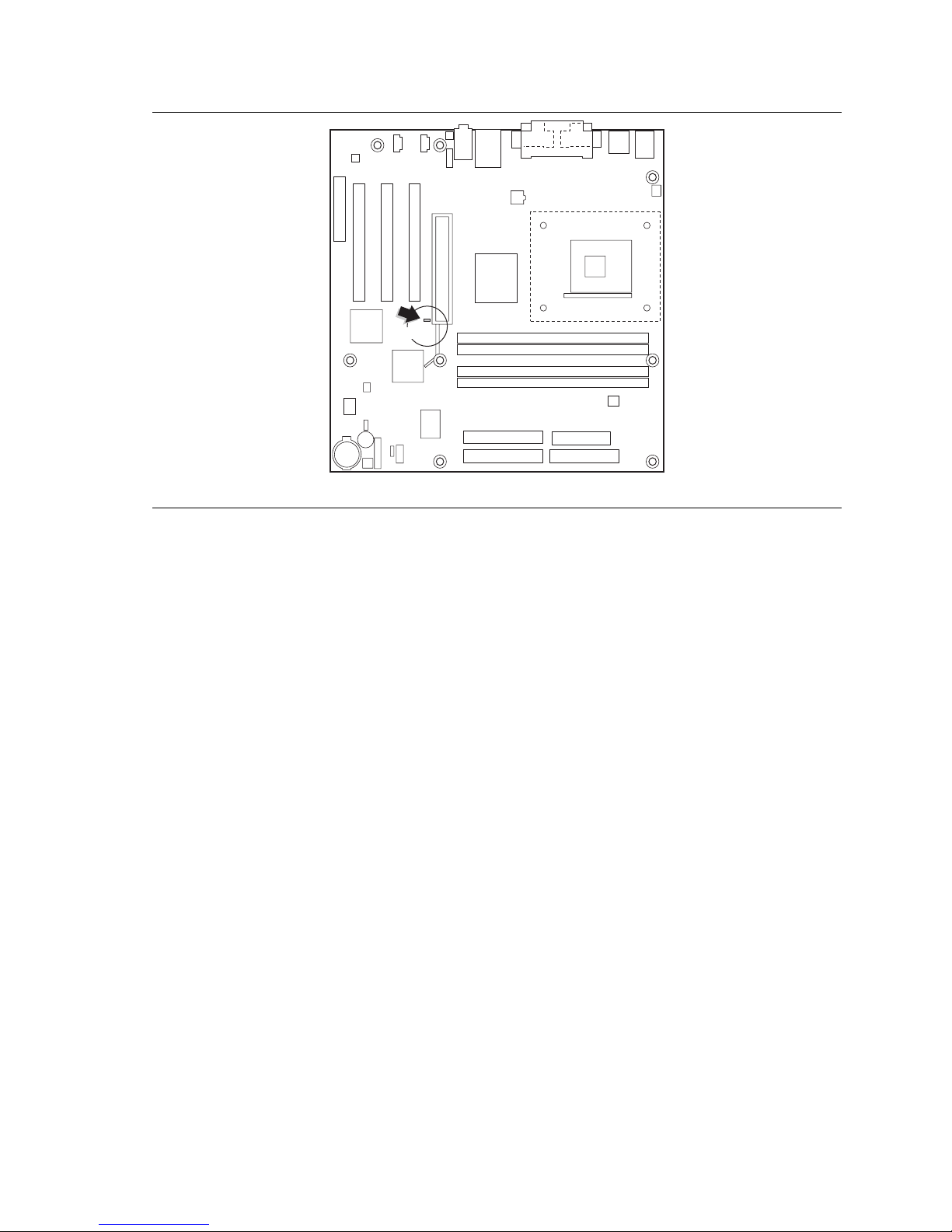
The board’s standby power indicator, shown in Figure 3 on page 19, is lit when there is standby
power to the system. This includes the memory modules and PCI bus connectors even when the
computer appears to be off.
If the system has a dual-colored power LED on the front panel, the sleep state is indicated by the
LED turning amber.
18
CR7F1
Desktop Board Features
OM11834
Figure 3. Location of Standby Power Indicator
Power supplies used with this board must be able to provide enough standby current to support the
standard Instantly Available (ACPI S3 sleep state) configuration as outlined in Table 4. Values are
determined by specifications such as PCI 2.2. Actual measurements may vary.
To estimate the total amount of standby current required for a particular system configuration,
standby current requirements of all installed components must be added. Refer to the descriptions
in Table 4 on page 20 and follow the steps outlined below:
1. Note the total D850MD or D850MV board standby current requirement.
2. Add to that the total PS/2 port standby current requirement if a wake-enabled device is
connected.
3. Add, from the PCI 2.2 slots (wake-enabled) row, the total of the number of wake-enabled
devices installed (PCI and AGP) multiplied by the standby current requirement.
4. Add, from the PCI 2.2 slots (nonwake-enabled) row, the total of the number of non-wakeenabled devices installed (PCI and AGP) multiplied by the standby current requirement.
5. Add all additional wake-enabled devices’ and non-wake-enabled devices’ standby current
requirements as applicable.
6. Add all the required current totals from steps 1 through 5 to determine the total estimated
standby current power supply requirement.
19

Intel Desktop Boards D850MD and D850MV Product Guide
Table 4. Standby Current Requirements
Instantly Available Current
Support Description
Estimate for integrated board
components
Estimate for add-on components
(Add to integrated board
components shown above)
* Refer to the Intel® Desktop Board D850MV/D850MD Technical Product Specification for the exact standby current
requirements
** Dependent upon system configuration
NOTE
✏
Total for the D850MD or D850MV
boards
PS/2 ports
PCI 2.2 slots (wake-enabled) 375
PCI 2.2 slots (non-wake-enabled) 100
CNR** (wake enabled) 875
CNR** (non-wake enabled) 40
USB ports
**
**
Standby Current
Requirements (mA)
770*
345
700
PCI requirements are calculated by totaling the following:
• One wake-enabled device @ 375 mA
• Five non- wake-enabled devices @ 20 mA each
PS/2 Ports requirements per the IBM PS/2 Port Specification (Sept 1991):
• Keyboard @ 275 mA
• Mouse @ 70 mA
USB requirements are calculated by totaling the following:
• One wake-enabled device @ 500 mA
• USB hub @ 100 mA
• Three USB non-wake-enabled devices @ 2.5 mA each
The USB ports are limited to a combined total of 700 mA.
Resume on Ring
The operation of Resume on Ring can be summarized as follows:
• Resumes operation from either the APM sleep mode or the ACPI S1 state
• Requires only one call to access the computer
• Detects incoming calls similarly for external and internal modems
• Requires modem interrupt be unmasked for correct operation
20

2 Installing and Replacing Desktop Board
Components
This chapter tells you how to:
• Install the I/O shield
• Install and remove the desktop board
• Install and remove a processor
• Install and remove memory
• Install and remove an AGP card retention mechanism and card
• Connect the IDE cable
• Set the BIOS jumper
• Clear passwords
• Replace the battery
Before You Begin
CAUTION
Before you install this board in a chassis, see Appendix B on page 81 for regulatory requirements
and precautions.
• Always follow the steps in each procedure in the correct order.
• Set up a log to record information about your computer, such as model, serial number,
installed options, and configuration information.
• Electrostatic discharge (ESD) can damage components. Perform the procedures described in
this chapter only at an ESD workstation using an antistatic wrist strap and a conductive foam
pad. If such a station is not available, you can provide some ESD protection by wearing an
antistatic wrist strap and attaching it to a metal part of the computer chassis.
WARNINGS
The procedures in this chapter assume familiarity with the general terminology associated with
personal computers and with the safety practices and regulatory compliance required for using
and modifying electronic equipment.
Disconnect the computer from its power source and from any telecommunications links,
networks, or modems before performing any of the procedures described in this chapter.
Failure to disconnect power, telecommunications links, networks, or modems before you open
the computer or perform any procedures can result in personal injury or equipment damage.
Some circuitry on the board can continue to operate even though the front panel power button
is off.
21
Intel Desktop Boards D850MD and D850MV Product Guide
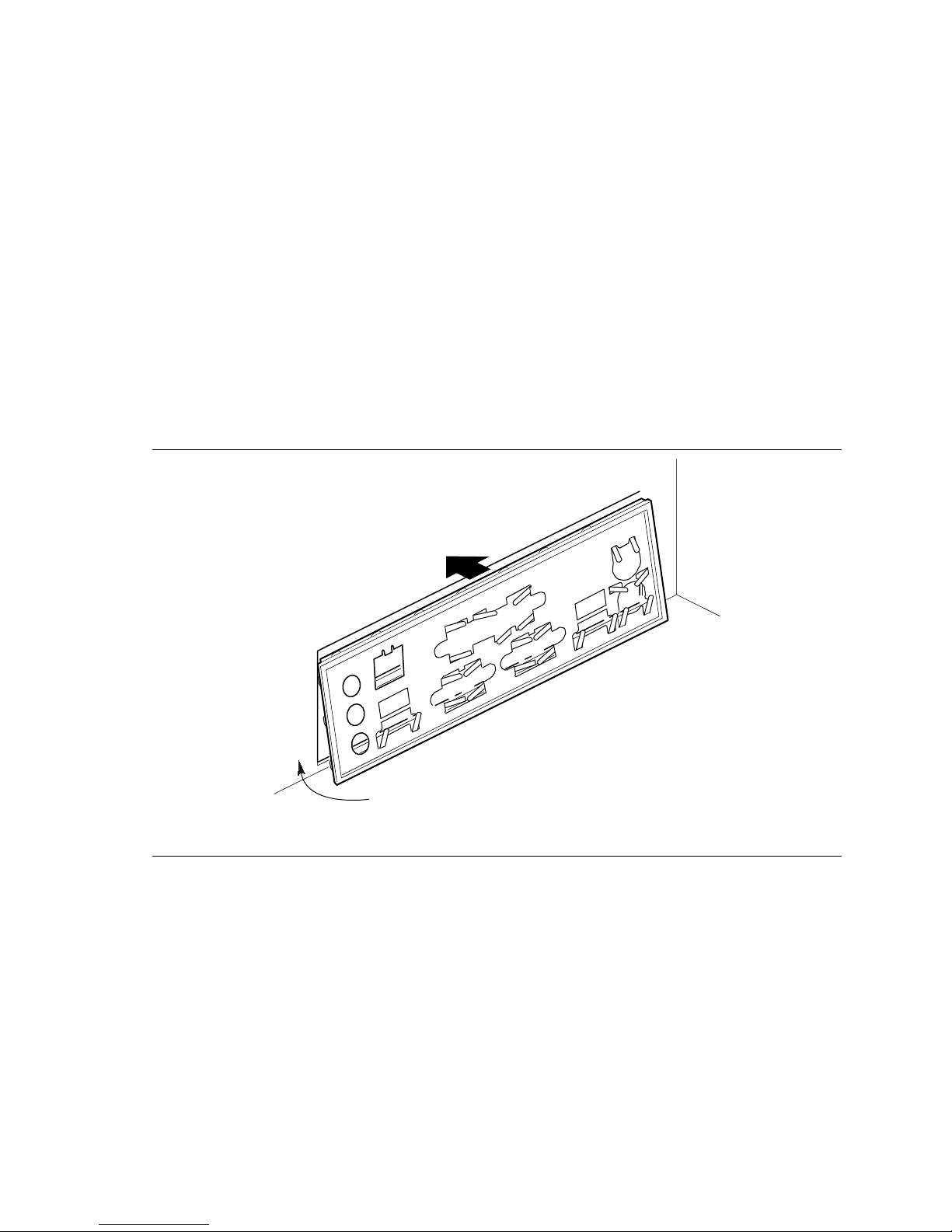
Installing the I/O Shield
NOTE
✏
Systems based on this desktop board require that the I/O shield be properly installed to comply
with Class B emissions requirements.
The desktop board comes with an I/O shield. When installed in the chassis, the shield blocks radio
frequency transmissions, protects internal components from dust and foreign objects, and promotes
correct airflow within the chassis.
Install the I/O shield before installing the desktop board in the chassis. Place the shield inside the
chassis as shown in the following figure. Press the shield into place so that it fits tightly and
securely. If the shield doesn’t fit, obtain a properly sized shield from the chassis supplier.
Figure 4 shows how the I/O shield is installed inside the chassis.
22
OM12116
Figure 4. Installing the I/O Shield
Installing and Replacing Desktop Board Components
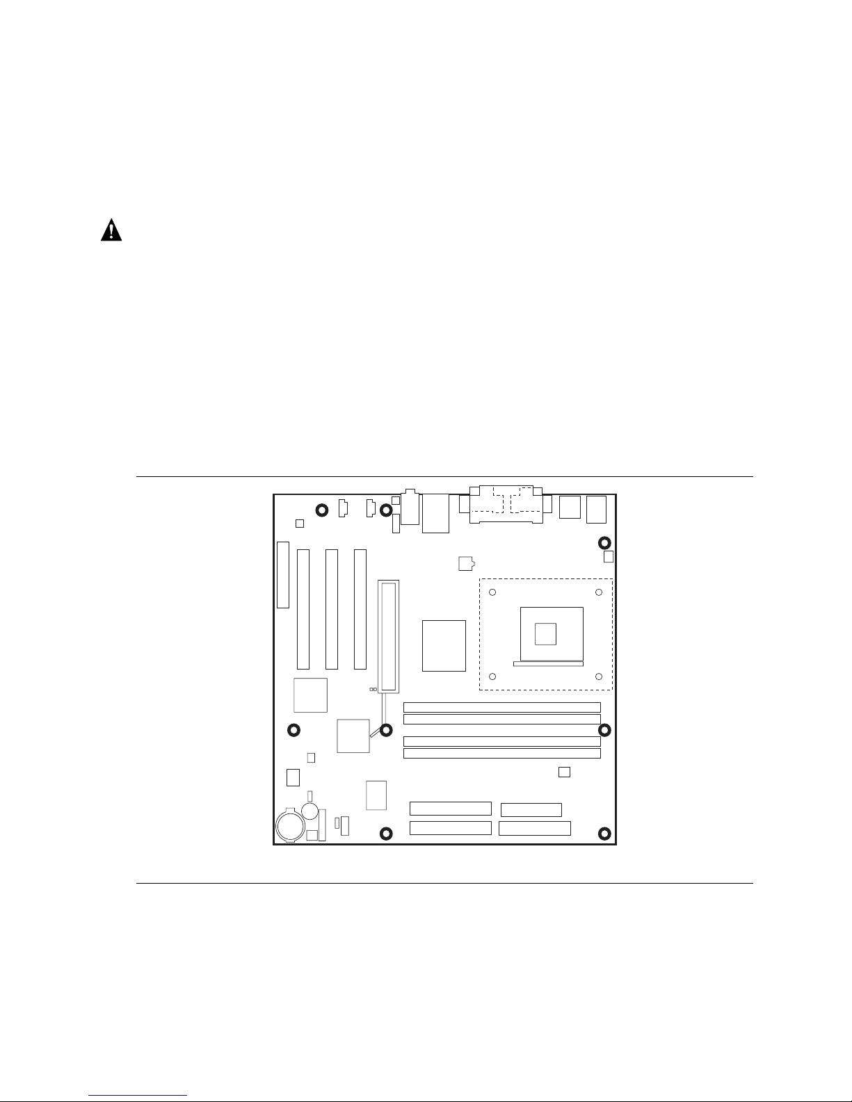
Installing and Removing the Desktop Board
Refer to your chassis manual for instructions on installing and removing the board. The D850MD
board is secured to the chassis by eight screws and the D850MV board by 11 screws. See Figure 5
and Figure 6 for the locations of the mounting screw holes of each board.
WARNING
This procedure should be done only by qualified technical personnel. Disconnect the computer
from its power source before performing the procedures described here. Failure to disconnect
the power before you open the computer can result in personal injury or equipment damage.
NOTES
✏
You will need a Phillips† (#2 bit) screwdriver.
Refer to Appendix B on page 81 for regulatory requirements and installation instructions and
precautions.
Figure 5 shows the location of the mounting holes for the D850MD board.
OM11831
Figure 5. D850MD Board Mounting Screw Holes
23
Intel Desktop Boards D850MD and D850MV Product Guide
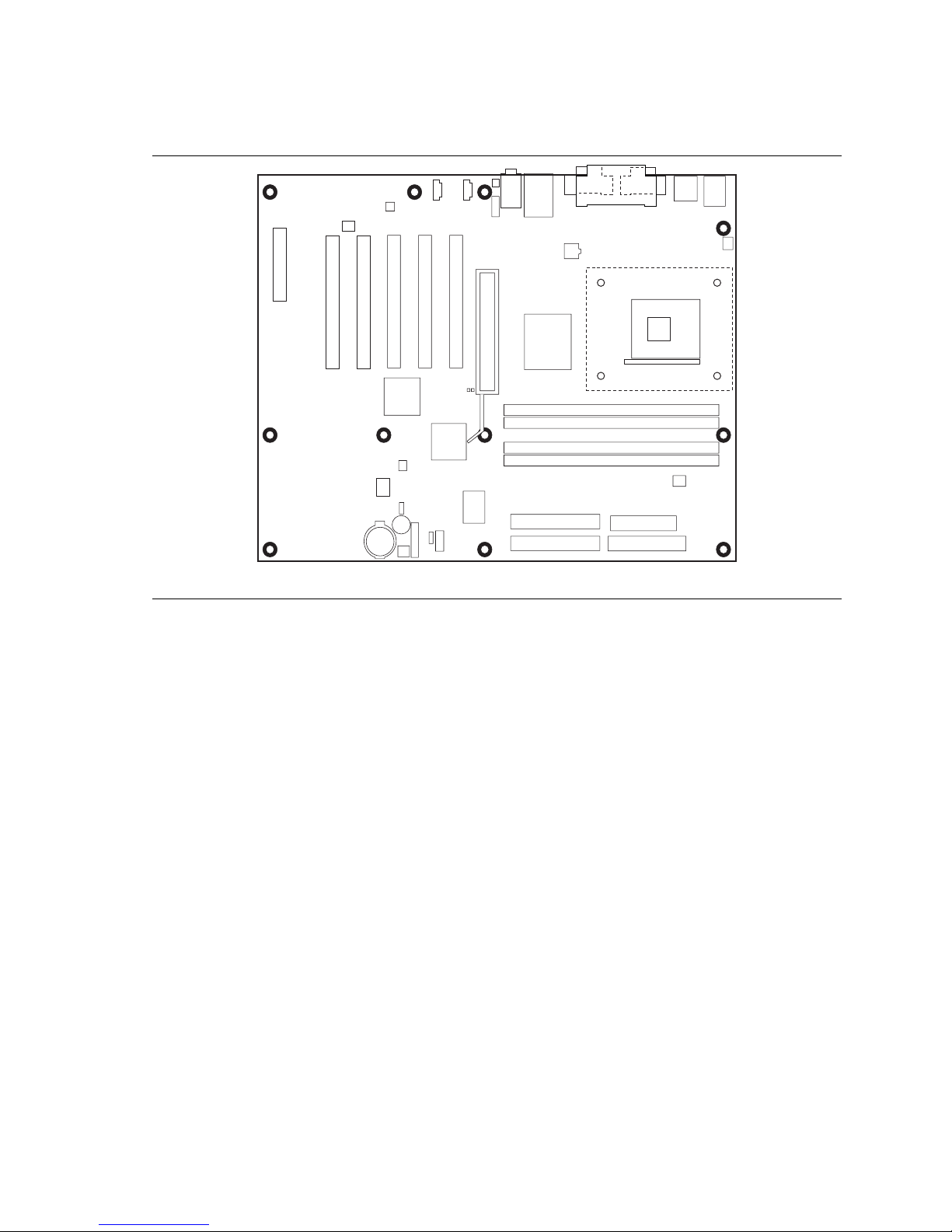
Figure 6 shows the location of the mounting holes for the D850MV board.
Figure 6. D850MV Board Mounting Screw Holes
OM12178
24
Installing and Replacing Desktop Board Components
Installing and Removing a Processor
Instructions on how to install the processor fan heatsink retention mechanism (RM) base and
processor to the desktop board are given below. For instruction on how to install the processor fan
heatsink, refer to the processor installation manual or the Intel World Wide Web site at:
http://support.intel.com/support/motherboards/desktop
Installing the Processor Fan Heatsink Retention Mechanism Base
NOTE
✏
The following assembly operation should be performed after the desktop board is secured in the
chassis.
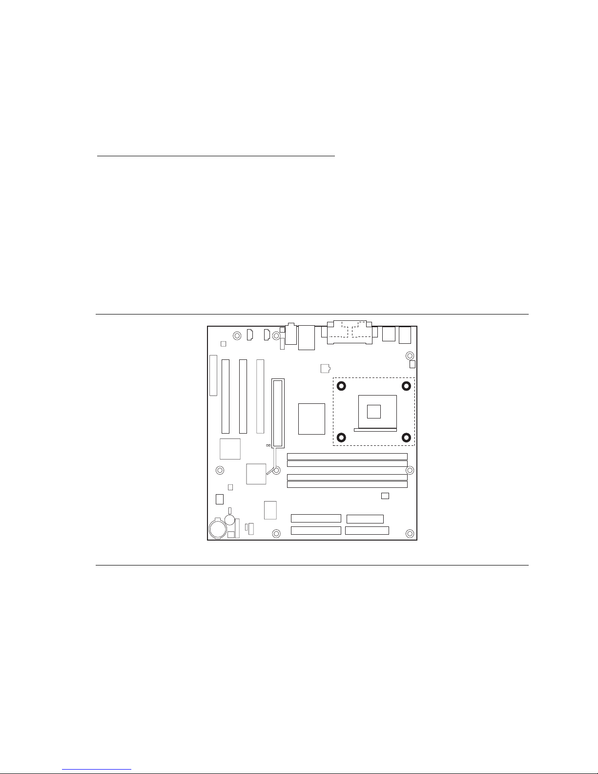
To install the processor fan heatsink RM base, follow these instructions:
1. Observe the precautions in “Before You Begin” on page 21.
2. Locate the processor fan heatsink RM holes on the desktop board (see Figure 7).
Figure 7. Location of the Processor Fan Heatsink Base Mounting Holes
OM12079
25
Intel Desktop Boards D850MD and D850MV Product Guide
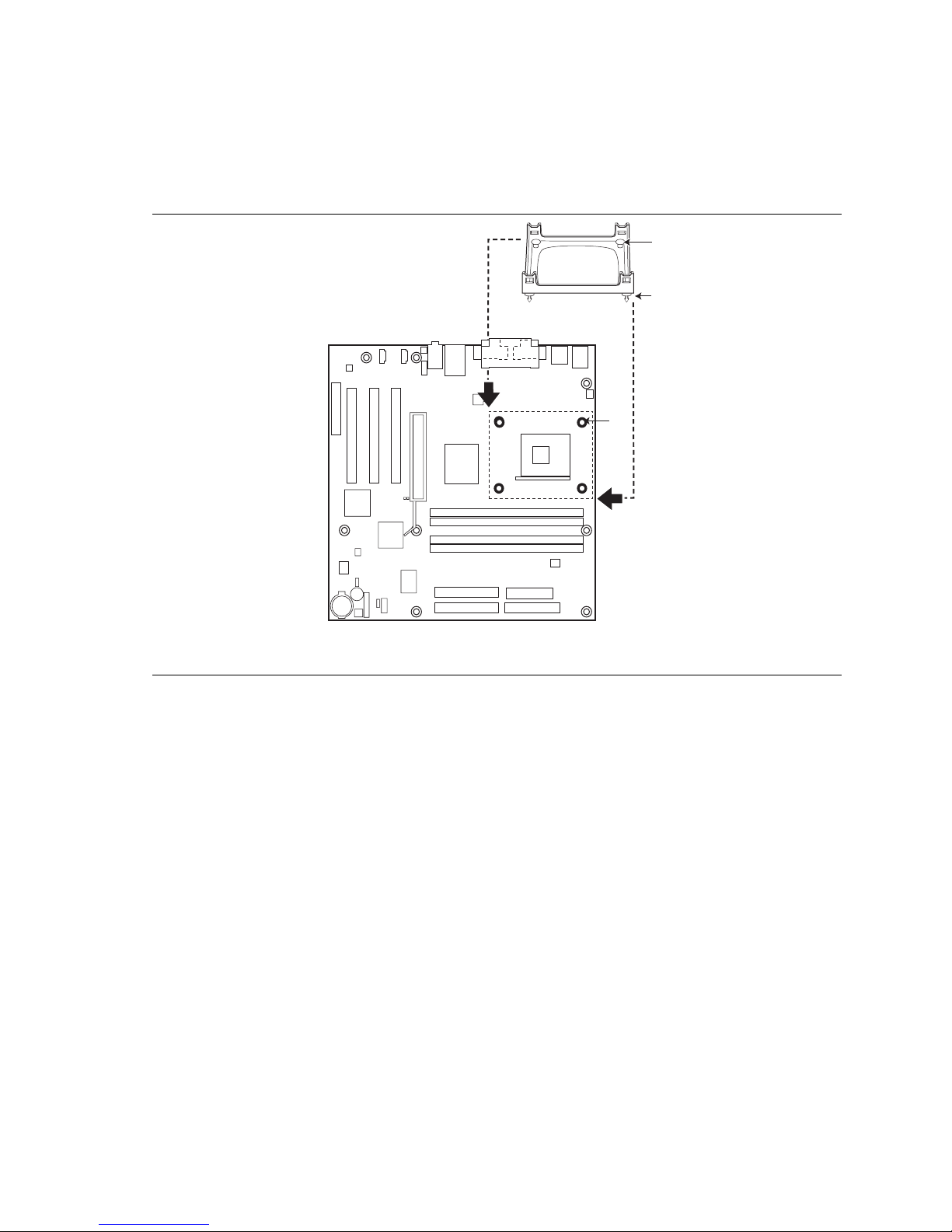
3. Align the four fasteners (B) of the processor fan heatsink RM base with the corresponding
holes in the desktop board (C). Gently press the base down until all four corners snap into
place. Verify that all four fasteners are fully engaged, then press down each of the four
locking pushpins (A) to fully secure the base to the desktop board (see Figure 8).
A
B
C
OM12177
Figure 8. Installing the Processor Fan Heatsink RM Base to the Board
26
 Loading...