

Page 1

Intel® Server Board S2600WT
Technical Product Specification (TPS)
Revision 1.0
August 2014
Intel® Server Boards and Systems
Page 2

Intel® Server Board S2600WT TPS
Date
Revision
Number
Modifications
August 2014
1..0
1st External Public Release
Revision History
ii Revision 1.0
Page 3

Intel® Server Board S2600WT TPS
Disclaimers
Information in this document is provided in connection with Intel® products. No license, express or implied, by estoppel or otherwise,
to any intellectual property rights is granted by this document. Except as provided in Intel's Terms and Conditions of Sale for such
products, Intel assumes no liability whatsoever, and Intel disclaims any express or implied warranty, relating to sale and/or use of
Intel products including liability or warranties relating to fitness for a particular purpose, merchantability, or infringement of any
patent, copyright or other intellectual property right. Intel products are not intended for use in medical, lifesaving, or life sustaining
applications. Intel may make changes to specifications and product descriptions at any time, without notice.
A "Mission Critical Application" is any application in which failure of the Intel Product could result, directly or indirectly, in personal
injury or death. SHOULD YOU PURCHASE OR USE INTEL'S PRODUCTS FOR ANY SUCH MISSION CRITICAL APPLICATION, YOU
SHALL INDEMNIFY AND HOLD INTEL AND ITS SUBSIDIARIES, SUBCONTRACTORS AND AFFILIATES, AND THE DIRECTORS,
OFFICERS, AND EMPLOYEES OF EACH, HARMLESS AGAINST ALL CLAIMS COSTS, DAMAGES, AND EXPENSES AND REASONABLE
ATTORNEYS' FEES ARISING OUT OF, DIRECTLY OR INDIRECTLY, ANY CLAIM OF PRODUCT LIABILITY, PERSONAL INJURY, OR DEATH
ARISING IN ANY WAY OUT OF SUCH MISSION CRITICAL APPLICATION, WHETHER OR NOT INTEL OR ITS SUBCONTRACTOR WAS
NEGLIGENT IN THE DESIGN, MANUFACTURE, OR WARNING OF THE INTEL PRODUCT OR ANY OF ITS PARTS.
Designers must not rely on the absence or characteristics of any features or instructions marked "reserved" or "undefined." Intel
reserves these for future definition and shall have no responsibility whatsoever for conflicts or incompatibilities arising from future
changes to them.
The Intel
published specifications. Current characterized errata are available on request.
This document and the software described in it are furnished under license and may only be used or copied in accordance with the
terms of the license. The information in this manual is furnished for informational use only, is subject to change without notice, and
should not be construed as a commitment by Intel Corporation. Intel Corporation assumes no responsibility or liability for any errors
or inaccuracies that may appear in this document or any software that may be provided in association with this document.
Except as permitted by such license, no part of this document may be reproduced, stored in a retrieval system, or transmitted in any
form or by any means without the express written consent of Intel Corporation.
Copies of documents which have an order number and are referenced in this document, or other Intel® Literature, may be obtained
by calling 1-800-548-4725, or go to: http://www.intel.com/design/Literature.htm.
Intel and Xeon are trademarks or registered trademarks of Intel Corporation.
*Other brands and names may be claimed as the property of others.
Copyright © 2014 Intel Corporation. All rights reserved.
®
Server Board S2600WT may contain design defects or errors known as errata which may cause the product to deviate from
.
Revision 1.0 iii
Page 4

Intel® Server Board S2600WT TPS
Table of Contents
1. Introduction ........................................................................................................................................ 1
1.1 Chapter Outline .................................................................................................................................... 1
1.2 Server Board Use Disclaimer .......................................................................................................... 1
2. Product Features Overview ............................................................................................................. 2
2.1 Server Board Component/Feature Identification .................................................................. 4
2.2 Product Architecture Overview ..................................................................................................... 8
2.3 System Software Overview ............................................................................................................. 9
2.3.1 System BIOS .......................................................................................................................................... 9
2.3.2 Field Replaceable Unit (FRU) and Sensor Data Record (SDR) Data ............................. 13
2.3.3 Baseboard Management Controller (BMC) & Management Engine (ME) Firmware13
3. Processor Support.......................................................................................................................... 14
3.1 Processor Socket Assembly ........................................................................................................ 14
3.2 Processor Thermal Design Power (TDP) Support .............................................................. 15
3.3 Processor Population Rules ......................................................................................................... 15
3.4 Processor Initialization Error Summary .................................................................................. 16
3.5 Processor Function Overview ..................................................................................................... 18
3.5.1 Processor Core Features: .............................................................................................................. 18
3.5.2 Supported Technologies: ............................................................................................................. 18
4. System Memory .............................................................................................................................. 21
4.1 Memory Sub-system Architecture ............................................................................................ 21
4.2 IMC Modes of operation ................................................................................................................ 22
4.3 Memory RASM Features ................................................................................................................ 22
4.4 Supported Memory ......................................................................................................................... 23
4.5 NVDIMM Support ............................................................................................................................. 24
4.6 Memory Slot Identification and Population Rules ............................................................. 24
4.6.1 Memory Interleaving Support ..................................................................................................... 27
4.6.2 NUMA Configuration Support ..................................................................................................... 27
4.7 System Memory Sizing and Publishing ................................................................................... 27
4.7.1 Effects of Memory Configuration on Memory Sizing ........................................................ 27
4.7.2 Publishing System Memory ......................................................................................................... 28
4.8 Memory Initialization ...................................................................................................................... 29
4.8.1 DIMM Discovery ............................................................................................................................... 29
4.8.2 DIMM Population Validation Check .......................................................................................... 29
4.8.3 Channel Training .............................................................................................................................. 30
5. System I/O ....................................................................................................................................... 32
5.1 PCIe* Support .................................................................................................................................... 32
iv Revision 1.0
Page 5

Intel® Server Board S2600WT TPS
5.2 PCIe* Enumeration and Allocation ........................................................................................... 33
5.3 PCIe* Non-Transparent Bridge (NTB) ...................................................................................... 33
5.4 Add-in Card Support ...................................................................................................................... 34
5.4.1 Riser Card Support .......................................................................................................................... 35
5.4.2 I/O Module Support ........................................................................................................................ 38
5.4.3 Intel
®
Integrated RAID Option ...................................................................................................... 39
5.5 Serial ATA (SATA) Support ........................................................................................................... 40
5.5.1 Staggered Disk Spin-Up ................................................................................................................ 42
5.6 Embedded SATA SW-RAID support ......................................................................................... 42
5.6.1 Intel
5.6.2 Intel
®
Rapid Storage Technology (RSTe) 4.0 ......................................................................... 42
®
Embedded Server RAID Technology 2 (ESRT2) ....................................................... 43
5.7 Network Interface ............................................................................................................................. 44
5.7.1 Intel® Ethernet Controller Options............................................................................................ 45
5.7.2 Factory Programmed MAC Address Assignments ............................................................. 45
5.8 Video Support ................................................................................................................................... 45
5.8.1 Dual Video and Add-In Video Adapters ................................................................................. 46
5.8.2 Setting Video Configuration Options using the BIOS Setup Utility ............................ 48
5.9 USB Support ....................................................................................................................................... 50
5.9.1 Low Profile eUSB SSD Support .................................................................................................. 50
5.10 Serial Ports .......................................................................................................................................... 51
6. System Security .............................................................................................................................. 53
6.1 BIOS Setup Utility Security Options Menu ............................................................................ 53
6.1.1 Password Setup ................................................................................................................................ 53
6.1.2 System Administrator Password Rights ................................................................................. 54
6.1.3 Authorized System User Password Rights and Restrictions .......................................... 54
6.1.4 Front Panel Lockout ........................................................................................................................ 54
6.2 Trusted Platform Module (TPM) Support .............................................................................. 55
6.2.1 TPM security BIOS ........................................................................................................................... 55
6.2.2 Physical Presence ............................................................................................................................ 56
6.2.3 TPM Security Setup Options ....................................................................................................... 56
6.3 Intel
®
Trusted Execution Technology ....................................................................................... 57
7. Platform Management ................................................................................................................... 58
7.1 Management Feature Set Overview ......................................................................................... 58
7.1.1 IPMI 2.0 Features Overview ......................................................................................................... 58
7.1.2 Non IPMI Features Overview ....................................................................................................... 59
7.2 Platform Management Features and Functions .................................................................. 61
7.2.1 Power Sub-system ........................................................................................................................... 61
7.2.2 Advanced Configuration and Power Interface (ACPI) ....................................................... 61
Revision 1.0 v
Page 6

Intel® Server Board S2600WT TPS
7.2.3 System Initialization ........................................................................................................................ 61
7.2.4 Watchdog Timer ............................................................................................................................... 62
7.2.5 System Event Log (SEL) ................................................................................................................. 62
7.3 Sensor Monitoring ........................................................................................................................... 62
7.3.1 Sensor Scanning ............................................................................................................................... 63
7.3.2 Sensor Rearm Behavior ................................................................................................................. 63
7.3.3 BIOS Event-Only Sensors ............................................................................................................. 64
7.3.4 Margin Sensors .................................................................................................................................. 64
7.3.5 IPMI Watchdog Sensor .................................................................................................................. 64
7.3.6 BMC Watchdog Sensor .................................................................................................................. 64
7.3.7 BMC System Management Health Monitoring ..................................................................... 64
7.3.8 VR Watchdog Timer ........................................................................................................................ 64
7.3.9 System Airflow Monitoring ........................................................................................................... 64
7.3.10 Thermal Monitoring ........................................................................................................................ 65
7.3.11 Processor Sensors ........................................................................................................................... 68
7.3.12 Voltage Monitoring .......................................................................................................................... 70
7.3.13 Fan Monitoring .................................................................................................................................. 70
7.3.14 Standard Fan Management .......................................................................................................... 72
7.3.15 Power Management Bus (PMBus*) ............................................................................................ 78
7.3.16 Power Supply Dynamic Redundancy Sensor ....................................................................... 78
7.3.17 Component Fault LED Control ................................................................................................... 79
7.3.18 NMI (Diagnostic Interrupt) Sensor ............................................................................................. 80
7.3.19 LAN Leash Event Monitoring ....................................................................................................... 80
7.3.20 Add-in Module Presence Sensor ............................................................................................... 80
7.3.21 CMOS Battery Monitoring ............................................................................................................. 80
8. Intel® Intelligent Power Node Manager (NM) Support Overview ........................................ 81
8.1 Hardware Requirements ............................................................................................................... 81
8.2 Features ................................................................................................................................................ 81
8.3 ME System Management Bus (SMBus*) interface ............................................................... 81
8.4 PECI 3.0 ................................................................................................................................................ 82
8.5 NM “Discovery” OEM SDR ............................................................................................................. 82
8.6 SmaRT/CLST ...................................................................................................................................... 82
8.6.1 Dependencies on PMBus*-compliant Power Supply Support ...................................... 83
9. Basic and Advanced Server Management Features ............................................................... 84
9.1 Dedicated Management Port ...................................................................................................... 85
9.2 Embedded Web Server .................................................................................................................. 85
9.3 Advanced Management Feature Support (RMM4 Lite) ................................................... 87
9.3.1 Keyboard, Video, Mouse (KVM) Redirection ......................................................................... 87
vi Revision 1.0
Page 7

Intel® Server Board S2600WT TPS
9.3.2 Remote Console ............................................................................................................................... 88
9.3.3 Performance ....................................................................................................................................... 88
9.3.4 Security ................................................................................................................................................. 89
9.3.5 Availability ........................................................................................................................................... 89
9.3.6 Usage ..................................................................................................................................................... 89
9.3.7 Force-enter BIOS Setup ................................................................................................................ 89
9.3.8 Media Redirection ............................................................................................................................ 89
10. On-board Connector/Header Overview .................................................................................... 91
10.1 Power Connectors ........................................................................................................................... 91
10.1.1 Main Power ......................................................................................................................................... 91
10.1.2 Hot Swap Backplane Power Connector .................................................................................. 92
10.1.3 Peripheral Drive Power Connector ........................................................................................... 93
10.1.4 Riser Card Supplemental 12V Power Connectors.............................................................. 93
10.2 Front Panel Headers and Connectors ..................................................................................... 94
10.2.1 Front Panel Button and LED Support ...................................................................................... 94
10.2.2 Front Panel LED and Control Button Features Overview ................................................ 95
10.2.3 Front Panel USB 2.0 Connector ................................................................................................. 96
10.2.4 Front Panel USB 3.0 Connector ................................................................................................. 97
10.2.5 Front Panel Video Connector ...................................................................................................... 97
10.2.6 Intel
®
Local Control Panel Connector ....................................................................................... 97
10.3 On-Board Storage Option Connectors ................................................................................... 98
10.3.1 Single Port SATA Only Connectors .......................................................................................... 98
10.3.2 Internal Type-A USB Connector ................................................................................................ 99
10.3.3 Internal 2mm Low Profile eUSB SSD Connector ................................................................ 99
10.4 System Fan Connectors .............................................................................................................. 100
10.5 Other Connectors and Headers .............................................................................................. 101
10.5.1 Chassis Intrusion Header ........................................................................................................... 101
10.5.2 Storage Device Activity LED Header ...................................................................................... 101
10.5.3 Intelligent Platform Management Bus (IPMB) Connector ............................................ 101
10.5.4 Hot Swap Backplane I2C* Connectors ................................................................................. 102
10.5.5 SMBus Connector.......................................................................................................................... 102
11. Reset and Recovery Jumpers..................................................................................................... 103
11.1 BIOS Default Jumper Block ...................................................................................................... 103
11.2 Serial Port ‘A’ Configuration Jumper .................................................................................... 104
11.3 Password Clear Jumper Block ................................................................................................. 104
11.4 Management Engine (ME) Firmware Force Update Jumper Block ........................... 104
11.5 BMC Force Update Jumper Block .......................................................................................... 105
11.6 BIOS Recovery Jumper ............................................................................................................... 106
Revision 1.0 vii
Page 8

Intel® Server Board S2600WT TPS
12. Light Guided Diagnostics ............................................................................................................ 107
12.1 System ID LED ................................................................................................................................ 108
12.2 System Status LED ........................................................................................................................ 108
12.3 BMC Boot/Reset Status LED Indicators ............................................................................... 111
12.4 Post Code Diagnostic LEDs ....................................................................................................... 111
12.5 Fan Fault LEDs ................................................................................................................................ 111
12.6 Memory Fault LEDs ...................................................................................................................... 111
12.7 CPU Fault LEDs ............................................................................................................................... 111
13. Power Supply Specification Guidelines .................................................................................. 112
13.1 Power Supply DC Output Connector .................................................................................... 112
13.2 Power Supply DC Output Specification ............................................................................... 113
13.2.1 Output Power/Currents .............................................................................................................. 113
13.2.2 Standby Output ............................................................................................................................. 113
13.2.3 Voltage Regulation ....................................................................................................................... 113
13.2.4 Dynamic Loading ........................................................................................................................... 113
13.2.5 Capacitive Loading ....................................................................................................................... 114
13.2.6 Grounding......................................................................................................................................... 114
13.2.7 Closed loop stability .................................................................................................................... 114
13.2.8 Residual Voltage Immunity in Standby mode ................................................................... 114
13.2.9 Common Mode Noise .................................................................................................................. 114
13.2.10 Soft Starting .................................................................................................................................... 114
13.2.11 Zero Load Stability Requirements ......................................................................................... 114
13.2.12 Hot Swap Requirements ............................................................................................................. 114
13.2.13 Forced Load Sharing .................................................................................................................... 114
13.2.14 Ripple/Noise .................................................................................................................................... 115
13.2.15 Timing Requirements .................................................................................................................. 115
Appendix A: Integration and Usage Tips ........................................................................................ 117
Appendix B: Integrated BMC Sensor Tables .................................................................................. 118
Appendix C: Management Engine Generated SEL Event Messages ......................................... 132
Appendix D: POST Code Diagnostic LED Decoder ....................................................................... 134
Appendix E: POST Code Errors ......................................................................................................... 141
Appendix F: Supported Intel
®
Server Systems .............................................................................. 147
viii Revision 1.0
Page 9

Intel® Server Board S2600WT TPS
List of Figures
Figure 1. Server Board Component/Features Identification ........................................................................ 4
Figure 2. Intel
Figure 3. Intel® Light Guided Diagnostics - DIMM Fault LEDs ...................................................................... 5
Figure 4. Intel
Figure 5. Jumper Block Identification .................................................................................................................... 7
Figure 6. Intel
Figure 7. Processor Socket Assembly ............................................................................................................... 14
Figure 8. LGA2011-3 ILM (Narrow) ...................................................................................................................... 14
Figure 9. Memory Sub-system Block Diagram ................................................................................................ 21
Figure 10. Memory Slots Definition ..................................................................................................................... 24
Figure 11. Intel
Figure 12. On-board Add-in Card Support ...................................................................................................... 34
Figure 13. 1U one slot PCIe* riser card (iPN – F1UL16RISER2) ................................................................ 36
®
Server Board S2600WT External I/O Connector Layout ................................................ 5
®
Light Guided Diagnostic LED Identification .......................................................................... 6
®
Server Board S2600WT Architectural Block Diagram ..................................................... 8
®
Server Board S2600WT Memory Slot Layout ................................................................ 25
Figure 14. 2U three PCIe* slot riser card (iPN – A2UL8RISER2) ............................................................... 36
Figure 15. 2U two PCIe* slot riser card (iPN – A2UL16RISER2) ............................................................... 37
Figure 16. 2U three PCIx/PCIe* slot riser (iPN - A2ULPCIXRISER2) ....................................................... 37
Figure 17. 2U two PCIe* slot (Low Profile) PCIe* Riser card (iPN – A2UX8X4RISER) – Riser Slot
#3 compatible only ............................................................................................................................................ 38
Figure 18. Server Board Layout - I/O Module Connector........................................................................... 38
Figure 19. Server Board Layout – Intel® Integrated RAID Module Option Placement .................... 39
Figure 20. Onboard SATA Features ..................................................................................................................... 40
Figure 21. SATA RAID 5 Upgrade Key................................................................................................................. 44
Figure 22. Network Interface Connectors ......................................................................................................... 44
Figure 23. External RJ45 NIC Port LED Definition ......................................................................................... 45
Figure 24. BIOS Setup Utility - Video Configuration Options ................................................................... 48
Figure 25. Onboard USB Port Support .............................................................................................................. 50
Figure 26. Low Profile eUSB SSD Support ....................................................................................................... 50
Figure 27. High-level Fan Speed Control Process ......................................................................................... 75
Figure 28. Intel
®
RMM4 Lite Activation Key Installation.............................................................................. 85
Figure 29. High Power Add-in Card 12V Auxiliary Power Cable Option .............................................. 93
Figure 30. System Fan Connector Pin-outs .................................................................................................. 100
Figure 31. System Fan Connector Placement .............................................................................................. 100
Figure 32. Reset and Recovery Jumper Block Location ........................................................................... 103
Figure 33. On-Board Diagnostic LED Placement ........................................................................................ 107
Figure 34. DIMM Fault LED Placement ............................................................................................................ 108
Figure 35. Turn On/Off Timing (Power Supply Signals) ........................................................................... 116
Revision 1.0 ix
Page 10

Intel® Server Board S2600WT TPS
Figure 36. POST Diagnostic LED Location ..................................................................................................... 134
Figure 37. Intel
Figure 38. Intel
®
Server System R1000WT .................................................................................................... 147
®
Server System R2000WT .................................................................................................... 150
x Revision 1.0
Page 11

Intel® Server Board S2600WT TPS
List of Tables
Table 1. Intel® Server Board S2600WT Feature Set ......................................................................................... 2
Table 2. POST Hot-Keys ........................................................................................................................................... 11
Table 3. Mixed Processor Configurations Error Summary ......................................................................... 16
Table 4. DDR4 RDIMM & LRDIMM Support ..................................................................................................... 23
Table 5. Intel
Table 6. DIMM Population Matrix ......................................................................................................................... 26
Table 7. PCIe* Port Routing CPU #1 .................................................................................................................... 32
Table 8. PCIe* Port Routing – CPU #2 ............................................................................................................... 33
Table 9. Riser Card #1 - PCIe* Root Port Mapping ........................................................................................ 35
Table 10. Riser Card #2 - PCIe* Root Port Mapping ..................................................................................... 35
Table 11. Riser Slot #3 - PCIe* Root Port Mapping ....................................................................................... 36
Table 12. Supported Intel
Table 13. SATA and sSATA Controller BIOS Utility Setup Options ....................................................... 41
®
Server Board S2600WT Memory Slot Identification ...................................................... 25
®
I/O Module Options ............................................................................................ 39
Table 14. SATA and sSATA Controller Feature Support ............................................................................ 41
Table 15. Video Modes ............................................................................................................................................. 46
Table 16. Serial A Connector Pin-out ................................................................................................................. 51
Table 17. Serial-B Connector Pin-out ................................................................................................................ 52
Table 18. TPM Setup Utility – Security Configuration Screen Fields .................................................... 57
Table 19. Server Board Power Control Sources ............................................................................................. 61
Table 20. ACPI Power States .................................................................................................................................. 61
Table 21. Processor Sensors .................................................................................................................................. 68
Table 22. Processor Status Sensor Implementation .................................................................................... 68
Table 23. Component Fault LEDs ......................................................................................................................... 79
Table 24. Intel
®
Remote Management Module 4 (RMM4) Options ......................................................... 84
Table 25. Basic and Advanced Server Management Features Overview ............................................. 84
Table 26. Main Power (Slot 1) Connector Pin-out (“MAIN PWR 1”) ...................................................... 91
Table 27. Main Power (Slot 2) Connector Pin-out ("MAIN PWR 2”) ....................................................... 92
Table 28. Hot Swap Backplane Power Connector Pin-out (“HSBP PWR") .......................................... 92
Table 29. Peripheral Drive Power Connector Pin-out ("Peripheral_PWR") ......................................... 93
Table 30. Riser Slot Auxiliary Power Connector Pin-out ("OPT_12V_PWR”) ..................................... 93
Table 31. Front Panel Features ............................................................................................................................. 94
Table 32. Front Panel Connector Pin-out ("Front Panel” and “Storage FP”) ...................................... 94
Table 33. Power/Sleep LED Functional States ............................................................................................... 95
Table 34. NMI Signal Generation and Event Logging .................................................................................. 96
Table 35. Front Panel USB 2.0 Connector Pin-out ("FP_USB_2.0_5-6 ") ............................................. 96
Table 36. Front Panel USB 2.0/3.0 Connector Pin-out (“FP_USB_2.0/ 3.0”) ..................................... 97
Revision 1.0 xi
Page 12

Intel® Server Board S2600WT TPS
Table 37. Front Panel Video Connector Pin-out ("FP VIDEO") ................................................................. 97
Table 38. Intel Local Control Panel Connector Pin-out ("LCP") ............................................................... 98
Table 39. Single Port SATA Connector Pin-out ("SATA 4" & "SATA 5") ............................................... 98
Table 40. SATA SGPIO Connector Pin-out ("SATA_SGPIO") ..................................................................... 99
Table 41. Internal Type-A USB Connector Pin-out ("USB 2.0") ............................................................... 99
Table 42. Internal eUSB Connector Pin-out ("eUSB SSD") ........................................................................ 99
Table 43. Chassis Intrusion Header Pin-out ("CHAS_INTR") .................................................................. 101
Table 44. Hard Drive Activity Header Pin-out ("HDD_LED") ................................................................... 101
Table 45. IPMB Connector Pin-out ................................................................................................................... 101
Table 46. Hot-Swap Backplane I2C* Connector Pin-out ......................................................................... 102
Table 47. SMBus Connector Pin-out ................................................................................................................ 102
Table 48. System Status LED State Definitions ........................................................................................... 109
Table 49. BMC Boot/Reset Status LED Indicators ...................................................................................... 111
Table 50. Power Supply DC Power Output Connector Pinout .............................................................. 112
Table 51. Minimum Load Ratings ...................................................................................................................... 113
Table 52. Voltage Regulation Limits ................................................................................................................ 113
Table 53. Transient Load Requirements ........................................................................................................ 113
Table 54. Capacitive Loading Conditions ....................................................................................................... 114
Table 55. Ripples and Noise ................................................................................................................................ 115
Table 56. Timing Requirements ......................................................................................................................... 115
Table 57. BMC Core Sensors ............................................................................................................................... 120
Table 58. Server Platform Services Firmware Health Event .................................................................. 132
Table 59. Node Manager Health Event ........................................................................................................... 133
Table 60. POST Progress Code LED Example .............................................................................................. 135
Table 61. MRC Progress Codes .......................................................................................................................... 135
Table 62. MRC Fatal Error Codes ....................................................................................................................... 136
Table 63. POST Progress Codes ........................................................................................................................ 138
Table 64. POST Error Codes and Messages.................................................................................................. 141
Table 65. POST Error Beep Codes .................................................................................................................... 146
Table 66. Integrated BMC Beep Codes ........................................................................................................... 146
Table 67. Intel® Server System R1000WT Product Family Feature Set ............................................. 147
Table 68. Intel
®
Server System R2000WT Product Family Feature Set ............................................. 150
xii Revision 1.0
Page 13

Intel® Server Board S2600WT TPS
<This page is intentionally left blank.>
Revision 1.0 xiii
Page 14

Page 15

Intel® Server Board S2600WT TPS
1. Introduction
This Technical Product Specification (TPS) provides board-specific information detailing the features,
functionality, and high-level architecture of the Intel
Design-level information related to specific server board components and subsystems can be obtained by
ordering External Product Specifications (EPS) or External Design Specifications (EDS) related to this server
generation. EPS and EDS documents are made available under NDA with Intel and must be ordered through
your local Intel
representative. See the Reference Documents section for a list of available documents.
1.1 Chapter Outline
This document is divided into the following chapters:
Chapter 1 – Introduction
Chapter 2 – Product Features Overview
Chapter 3 – Processor Support
Chapter 4 – System Memory
®
Server Board S2600WT.
Chapter 5 – System I/O
Chapter 6 – System Security
Chapter 7 – Platform Management
Chapter 8 – Intel
®
Intelligent Power Node Manager (NM) Support Overview
Chapter 9 – Basic and Advanced Server Management Features
Chapter 10 – On-Board Connector and Header Overview
Chapter 11 – Reset and Recovery Jumpers
Chapter 12 – Light-Guided Diagnostics
Chapter 13 – Power Supply Specification Guidelines
Appendix A – Integration and Usage Tips
Appendix B – Integrated BMC Sensor Tables
Appendix C – Management Engine Generated SEL Event Messages
Appendix D – POST Code Diagnostic LED Decoder
Appendix E – POST Code Errors
Appendix F – Supported Intel
®
Server Systems
1.2 Server Board Use Disclaimer
Intel Corporation server boards support add-in peripherals and contain a number of high-density VLSI and
power delivery components that need adequate airflow to cool. Intel ensures through its own chassis
development and testing that when Intel
system will meet the intended thermal requirements of these components. It is the responsibility of the
system integrator who chooses not to use Intel developed server building blocks to consult vendor
datasheets and operating parameters to determine the amount of airflow required for their specific
application and environmental conditions. Intel Corporation cannot be held responsible if components fail
or the server board does not operate correctly when used outside any of its published operating or
non-operating limits.
server building blocks are used together, the fully integrated
1 Revision 1.0
Page 16

Intel® Server Board S2600WT TPS
Feature
Description
• Two LGA2011-3 (Socket R3) processor sockets
• DB-15 Video connector
• One Type-A USB 2.0 connector
PCIe* Support
• PCIe* 3.0 (2.5, 5, 8 GT/s) – backwards compatible with PCIe* Gen 1 and Gen 2 devices
o Riser #2 – PCIe* 3.0 x24 – 1 PCIe* Full Height / Half Length add-in card support in 1U
2. Product Features Overview
The Intel® Server Board S2600WT is a monolithic printed circuit board assembly with features that are
intended for high density 1U and 2U rack mount servers. This server board is designed to support the Intel
®
processor E5-2600 v3 product family. Previous generation Intel® Xeon® processors are not supported.
Xeon
The server board is offered with either of the two following on-board networking options:
• Intel
• Intel
All other onboard features will be identical.
®
Ethernet Controller X540, supporting 10 GbE (Intel Server Board Product Code - S2600WTT)
®
Ethernet Controller I350, supporting 1 GbE (Intel Server Board Product Code – S2600WT2)
Table 1. Intel® Server Board S2600WT Feature Set
®
Processor Support
Memory
Chipset Intel® C612 chipset
External (Back Panel)
I/O connections
Internal I/O
connectors/headers
• Support for one or two Intel
• Maximum supported Thermal Design Power (TDP) of up to 145 W
• 24 DIMM slots – 3 DIMMs/Channel – 4 memory channels per processor
• Registered DDR4 (RDIMM), Load Reduced DDR4 (LRDIMM)
• Memory data transfer rates:
• DDR4 standard I/O voltage of 1.2V
• RJ-45 Serial Port A connector
• Dual RJ-45 Network Interface connectors supporting either :
• Dedicated RJ-45 server management port
• Three USB 2.0 / 3.0 connectors
• One 2x5 pin connector providing front panel support for two USB 2.0 ports
• One 2x10 pin connector providing front panel support for two USB 2.0 / 3.0 ports
• One 2x15 pin SSI-EEB compliant Standard Front Panel header
• One 2x15 high density Storage Front Panel connector
• One 2x7pin Front Panel Video connector
• One 1x7pin header for optional Intel
• One DH-10 Serial Port B connector
®
Xeon® processors E5-2600 v3 product family
o DDR4 RDIMM: 1600 MT/s (3DPC), 1866 MT/s (2DPC) and 2133 MT/s (1DPC)
o DDR4 LRDIMM: 1600 MT/s (3DPC), 2133 MT/s (2DPC & 1DPC)
o 10 GbE RJ-45 connectors (Intel Server Board Product Code – S2600WTT)
or
o 1 GbE RJ-45 connectors (Intel Server Board Product Code – S2600WT2)
®
Local Control Panel support
1U Server – Riser Card
Support
• Server board includes two PCIe* 3.0 compatible riser card only slots
o Riser #1 – PCIe* 3.0 x24 – 1 PCIe* Full Height / Half Length add-in card support in 1U
Revision 1.0 2
Page 17

Feature
Description
2U Server – Riser Card
• Server board includes three PCIe* 3.0 compatible riser card only slots:
o 2 low profile add-in cards via Riser #3
The server board includes a proprietary on-board connector allowing for the installation of a variety of
• Six system fans supported in two different connector formats: hot swap (2U) and cabled (1U)
•
•
o
•
• Integrated Baseboard Management Controller, IPMI 2.0 compliant
Support
Available I/O Module
Options
Intel® Server Board S2600WT TPS
o Riser #1 – PCIe* 3.0 x24 – up to 3 PCIe* slots in 2U
o Riser #2 – PCIe* 3.0 x24 – up to 3 PCIe* slots in 2U
o Riser #3 – PCIe* 3.0 x8 + DMI x4 (PCIe* 2.0 compatible) – up to 2 PCIe* slots in 2U
• With three riser cards installed, up to 8 possible add-in cards can be supported:
o 4 Full Height / Full Length + 2 Full Height / Half Length add-in cards via Risers #1 and #2
available I/O modules. An installed I/O module can be supported in addition to standard on-board
features and add-in PCIe* cards.
• AXX4P1GBPWLIOM – Quad port RJ45 1 GbE based on Intel® Ethernet Controller I350
• AXX10GBTWLIOM – Dual port RJ-45 10GBase-T I/O Module based on Intel® Ethernet Controller
x540
• AXX10GBNIAIOM – Dual port SFP+ 10 GbE module based on Intel® 82599 10 GbE controller
• AXX1FDRIBIOM – Single port QSFP FDR 56 GT/S speed InfiniBand* module
• AXX2FDRIBIOM – Dual port QSFP FDR 56 GT/S speed infiniband* module
• AXX1P40FRTIOM – Single port QSFP+ 40 GbE module
• AXX2P40FRTIOM – Dual port QSFP+ 40 GbE module
System Fan Support
Video
On-board storage
controllers and
options
Security
Server Management
o Six 10-pin managed system fan headers (Sys_Fan 1-6) – Used for 1U system configuration
o Six 6-pin hot swap capable managed system fan connectors (Sys_Fan 1-6) – Used for 2U system
configuration
Integrated 2D Video Controller
• 16 MB DDR3 Memory
10x SATA 6Gbps ports (6Gb/s, 3 Gb/s and 1.5Gb/s transfer rates are supported)
o Two 7-pin single port SATA connectors capable of supporting up to 6 Gb/sec
o Two 4-port mini-SAS HD (SFF-8643) connectors capable of supporting up to 6 Gb/sec SATA
• One eUSB 2x5 pin connector to support 2mm low-profile eUSB solid state devices
• Optional SAS IOC/ROC support via on-board Intel® Integrated RAID module connector
• Embedded Software SATA RAID
®
o Intel
Intel
Rapid Storage RAID Technology (RSTe) 4.0
®
Embedded Server RAID Technology 2 (ESRT2) with optional RAID 5 key support
Intel® Trusted Platform Module (TPM) - AXXTPME5 (Accessory Option)
• Support for Intel
®
Server Management Software
• On-board RJ45 management interface
®
• Intel
Remote Management Module 4 Lite support (Accessory Option)
3 Revision 1.0
Page 18

Intel® Server Board S2600WT TPS
2.1 Server Board Component/Feature Identification
The following illustration provides a general overview of the server board, identifying key feature and
component locations.
Figure 1. Server Board Component/Features Identification
Revision 1.0 4
Page 19

Intel® Server Board S2600WT TPS
The back edge of the server board includes several external connectors to support the following features:
A – RJ45 Networking Port – NIC #1
B – RJ45 Networking Port – NIC #2
C – Video
D – RJ45 Serial ‘A’ Port
E – Stacked 3-port USB 2.0 / 3.0
F – RJ45 Dedicated Management Port
®
Figure 2. Intel
Server Board S2600WT External I/O Connector Layout
Figure 3. Intel® Light Guided Diagnostics - DIMM Fault LEDs
5 Revision 1.0
Page 20

Intel® Server Board S2600WT TPS
Figure 4. Intel® Light Guided Diagnostic LED Identification
Note: See Appendix D for POST Code Diagnostic LED decoder information
Revision 1.0 6
Page 21

Intel® Server Board S2600WT TPS
Figure 5. Jumper Block Identification
See Chapter 11 - Reset & Recovery Jumpers for additional details.
7 Revision 1.0
Page 22

Intel® Server Board S2600WT TPS
DDR4 – CH0
DDR4 – CH1
DDR4 – CH2
DDR4 – CH3
Intel® Xeon®
Product Family
QPI 9.6 GT/s
QPI 9.6 GT/s
CH0
CH1 – DDR4
CH2 – DDR4
CH3 – DDR4
Riser Slot #3
PCIe* 3.0 x16 (32 GB/s)
PCIe*
PCIe* 3.0 x8 (16 GB/s)
PCIe* 3.0 x8 (16GB/s)
Riser Slot #1
Riser Slot #2
Intel®
Dual Port
10 GbE
PCIe* 2.0 x8 (10 GB/s)
Intel® C612
Integrated
Dedicated Management NIC
RMM4 Lite (Option)
Serial Port B
DH-10 Internal
RJ45 External
Serial A Jumper
DCD/DSR
Video
FP Header
Video
Shared Mgmt
Mbps
1 GbE
PHY
BMC Flash
16MB
SPI
NCSI
NCSI
128 MB
DDR3
PCIe* 1.0 x1
USB 2.0 (4,12)
TPM (Option)
DMI x4 (PCIe* 2.0) (4 GB/s)
Port Back Panel
16MB
SPI
PCIe* 3.0 x8 (16GB/s)
(Ports 0:3) – SATA
(Ports 0:3) - sSATA
Dual Mini-
Connectors
(Port 4) - SATA – 6 Gbps
(Port 5) - SATA – 6 Gbps
Rev 1.2
DMI x4 (PCIe* 2.0) (4 GB/s)
USB 2.0 & USB 3.0 I/O Ports
SATA RAID 5 Upgrade Key
PCIe* 3.0 x8 (16 GB/s)
PCIe* 3.0 x8 (16
2.2 Product Architecture Overview
The architecture of Intel® Server Board S2600WT is developed around the integrated features and functions
of the Intel
I350 1 GbE or X540 10 GbE, and the Emulex* Pilot-III Baseboard Management Controller.
The following diagram provides an overview of the server board architecture, showing the features and
interconnects of each of the major sub-system components.
®
Xeon® processor E5-2600 v3 product family, the Intel® C612 chipset, Intel® Ethernet Controllers
– DDR4
Intel® Xeon®
E5-2600 v3
Product Family
E5-2600 v3
SAS HD
Internal Mount
LP eUSB SSD
(Option)
USB 2.0 (8)
BIOS Flash
Series Chipset
3.0 x16 (32
1 GbE or
Ethernet
Controller
I350 or X540
Port - 50/100
BMC
Serial Port A
Revision 1.0 8
USB 2.0 (3)
Internal
Mount
Type-A
Dual Port Front
Panel Header
USB 2.0 (5,6)
Dual Port Front
Panel Header
USB 3.0 (1,4)
USB 2.0 (10,13)
Stacked Triple
USB 3.0 ( 2,3,5)
USB 2.0 (0,1,2)
Figure 6. Intel® Server Board S2600WT Architectural Block Diagram
Page 23

Intel® Server Board S2600WT TPS
2.3 System Software Overview
The server board includes an embedded software stack to enable, configure, and support various system
functions. This software stack includes the System BIOS, Baseboard Management Controller (BMC)
Firmware, Management Engine (ME) Firmware, and management support data including Field Replaceable
Unit (FRU) data, and Sensor Data Record (SDR) data.
The system software is pre-programmed on the server board during factory assembly, making the server
board functional at first power on after system integration. Typically, as part of the initial system integration
process, FRU and SDR data will have to be installed onto the server board by the system integrator to ensure
the embedded platform management subsystem is able to provide best performance and cooling for the
final system configuration. It is also not uncommon for the system software stack to be updated to later
revisions to ensure the most reliable system operation. Intel makes periodic system software updates
available for download at the following Intel website:
http://downloadcenter.intel.com
System updates can be performed in a number of operating environments, including the uEFI Shell using the
uEFI only System Update Package (SUP), or under different operating systems using the Intel
Flash Update Utility (OFU).
Reference the following Intel documents for more in-depth information about the system software stack and
their functions:
®
Intel
Intel
Server System BIOS External Product Specification for Intel® Servers Systems supporting the Intel®
®
processor E5-2600 v3 product family
Xeon
®
Server System BMC Firmware External Product Specification for Intel® Servers Systems supporting
®
the Intel
Xeon® processor E5-2600 v3 product family
®
One Boot
2.3.1 System BIOS
The system BIOS is implemented as firmware that resides in flash memory on the server board. The BIOS
provides hardware-specific initialization algorithms and standard compatible basic input/output services,
and standard Intel® Server Board features. The flash memory also contains firmware for certain embedded
devices.
This BIOS implementation is based on the Extensible Firmware Interface (EFI), according to the Intel®
Platform Innovation Framework for EFI architecture, as embodied in the industry standards for Unified
Extensible Firmware Interface (UEFI).
The implementation is compliant with all Intel® Platform Innovation Framework for EFI architecture
specifications, as further specified in the Unified Extensible Firmware Interface Reference Specification,
Version 2.3.1.
In the UEFI BIOS design, there are three primary components: the BIOS itself, the Human Interface
Infrastructure (HII) that supports communication between the BIOS and external programs, and the Shell
which provides a limited OS-type command-line interface. This BIOS system implementation complies with
HII Version 2.3.1, and includes a Shell.
9 Revision 1.0
Page 24

Intel® Server Board S2600WT TPS
2.3.1.1 BIOS Revision Identification
The BIOS Identification string is used to uniquely identify the revision of the BIOS being used on the server.
The BIOS ID string is displayed on the Power On Self Test (POST) Diagnostic Screen and in the <F2> BIOS
Setup Main Screen, as well as in System Management BIOS (SMBIOS) structures.
The BIOS ID string for S2600 series server boards is formatted as follows:
BoardFamilyID.OEMID.MajorVer.MinorVer.RelNum.BuildDateTime
Where:
• BoardFamilyID = String name to identify board family.
“SE5C610” is used to identify BIOS builds for Intel® S2600 series Server Boards, based on the
Intel® Xeon® Processor E5-2600 v3 product families and the Intel® C612 chipset.
• OEMID = Three-character OEM BIOS Identifier, to identify the board BIOS “owner”.
“86B” is used for Intel PCSD Commercial BIOS Releases.
• MajorVer = Major Version, two decimal digits 01-99 which are changed only to identify major
hardware or functionality changes that affect BIOS compatibility between boards.
“01” is the starting BIOS Major Version for all platforms.
• MinorVer = Minor Version, two decimal digits 00-99 which are changed to identify less significant
hardware or functionality changes which do not necessarily cause incompatibilities but do display
differences in behavior or in support of specific functions for the board.
• RelNum = Release Number, four decimal digits which are changed to identify distinct BIOS Releases.
BIOS Releases are collections of fixes and/or changes in functionality, built together into a BIOS
Update to be applied to a Server Board. However, there are “Full Releases” which may introduce
many new fixes/functions, and there are “Point Releases” which may be built to address very specific
fixes to a Full Release.
The Release Numbers for Full Releases increase by 1 for each release. For Point Releases, the first
digit of the Full Release number on which the Point Release is based is increased by 1. That digit is
always 0 (zero) for a Full Release.
• BuildDateTime = Build timestamp – date and time in MMDDYYYYHHMM format:
MM = Two-digit month.
DD = Two-digit day of month.
YYYY = Four-digit year.
HH = Two-digit hour using 24-hour clock.
MM = Two-digit minute.
An example of a valid BIOS ID String is as follows:
SE5C610.86B.01.01.0003.081320110856
The BIOS ID string is displayed on the POST diagnostic screen for BIOS Major Version 01, Minor Version 01,
Full Release 0003 that is generated on August 13, 2011 at 8:56 AM.
The BIOS version in the <F2> BIOS Setup Utility Main Screen is displayed without the time/date timestamp,
which is displayed separately as “Build Date”:
SE5C610.86B.01.01.0003
Revision 1.0 10
Page 25

Intel® Server Board S2600WT TPS
HotKey Combination
Function
<F2>
Enter the BIOS Setup Utility
<F6>
Pop-up BIOS Boot Menu
2.3.1.2 Hot Keys Supported During POST
Certain “Hot Keys” are recognized during POST. A Hot Key is a key or key combination that is recognized as
an unprompted command input, that is, the operator is not prompted to press the Hot Key and typically the
Hot Key will be recognized even while other processing is in progress.
The BIOS recognizes a number of Hot Keys during POST. After the OS is booted, Hot Keys are the
responsibility of the OS and the OS defines its own set of recognized Hot Keys.
The following table provides a list of available POST Hot Keys along with a description for each.
Table 2. POST Hot-Keys
<F12> Network boot
<Esc> Switch from Logo Screen to Diagnostic Screen
<Pause> Stop POST temporarily
2.3.1.3 POST Logo/Diagnostic Screen
The Logo/Diagnostic Screen appears in one of two forms:
If Quiet Boot is enabled in the <F2> BIOS setup, a “splash screen” is displayed with a logo image,
which may be the standard Intel Logo Screen or a customized OEM Logo Screen. By default, Quiet
Boot is enabled in BIOS setup, so the Logo Screen is the default POST display. However, if the logo is
displayed during POST, the user can press <Esc> to hide the logo and display the Diagnostic Screen
instead.
If a customized OEM Logo Screen is present in the designated Flash Memory location, the OEM Logo
Screen will be displayed, overriding the default Intel Logo Screen.
If a logo is not present in the BIOS Flash Memory space, or if Quiet Boot is disabled in the system
configuration, the POST Diagnostic Screen is displayed with a summary of system configuration
information. The POST Diagnostic Screen is purely a Text Mode screen, as opposed to the Graphics
Mode logo screen.
If Console Redirection is enabled in Setup, the Quiet Boot setting is disregarded and the Text Mode
Diagnostic Screen is displayed unconditionally. This is due to the limitations of Console Redirection,
which transfers data in a mode that is not graphics-compatible.
2.3.1.4 BIOS Boot Pop-Up Menu
The BIOS Boot Specification (BBS) provides a Boot Pop-up menu that can be invoked by pressing the <F6>
key during POST. The BBS Pop-up menu displays all available boot devices. The boot order in the pop-up
menu is not the same as the boot order in the BIOS setup. The pop-up menu simply lists all of the available
devices from which the system can be booted, and allows a manual selection of the desired boot device.
When an Administrator password is installed in Setup, the Administrator password will be required in order
to access the Boot Pop-up menu using the <F6> key. If a User password is entered, the Boot Pop-up menu
will not even appear – the user will be taken directly to the Boot Manager in the Setup, where a User
password allows only booting in the order previously defined by the Administrator.
11 Revision 1.0
Page 26

Intel® Server Board S2600WT TPS
2.3.1.5 Entering BIOS Setup
To enter the BIOS Setup Utility using a keyboard (or emulated keyboard), press the <F2> function key during
boot time when the OEM or Intel Logo Screen or the POST Diagnostic Screen is displayed.
The following instructional message is displayed on the Diagnostic Screen or under the Quiet Boot Logo
Screen:
Press <F2> to enter setup, <F6> Boot Menu, <F12> Network Boot
Note: With a USB keyboard, it is important to wait until the BIOS “discovers” the keyboard and beeps – until
the USB Controller has been initialized and the USB keyboard activated, key presses will not be read by the
system.
When the Setup Utility is entered, the Main screen is displayed initially. However, in the event a serious error
occurs during POST, the system will enter the BIOS Setup Utility and display the Error Manager screen
instead of the Main screen.
Reference the following Intel document for additional BIOS Setup information:
®
Server System BIOS Setup Guide for Intel® Servers Systems supporting the Intel® Xeon® processor E5-
Intel
2600 V3 product family
2.3.1.6 BIOS Update Capability
In order to bring BIOS fixes or new features into the system, it will be necessary to replace the current
installed BIOS image with an updated one. The BIOS image can be updated using a standalone IFLASH32
utility in the uEFI shell, or can be done using the OFU utility program under a supported operating system.
Full BIOS update instructions are provided when update packages are downloaded from the Intel web site.
2.3.1.7 BIOS Recovery
If a system is completely unable to boot successfully to an OS, hangs during POST, or even hangs and fails to
start executing POST, it may be necessary to perform a BIOS Recovery procedure, which can replace a
defective copy of the Primary BIOS.
The BIOS provides three mechanisms to start the BIOS recovery process, which is called Recovery Mode:
• Recovery Mode Jumper – this jumper causes the BIOS to boot in Recovery Mode
• The Boot Block detects partial BIOS update and automatically boots in Recovery Mode
• The BMC asserts Recovery Mode GPIO in case of partial BIOS update and FRB2 time-out
The BIOS Recovery takes place without any external media or Mass Storage device as it utilizes a Backup
BIOS image inside the BIOS flash in Recovery Mode.
The Recovery procedure is included here for general reference. However, if in conflict, the instructions in the
BIOS Release Notes are the definitive version.
When the BIOS Recovery Jumper is set (See Figure 5. Jumper Block Identification), the BIOS begins by
logging a ‘Recovery Start’ event to the System Event Log (SEL). It then loads and boots with a Backup BIOS
image residing in the BIOS flash device. This process takes place before any video or console is available.
The system boots to the embedded uEFI shell, and a ‘Recovery Complete’ event is logged to the SEL. From
the uEFI Shell, the BIOS can then be updated using a standard BIOS update procedure, defined in Update
Revision 1.0 12
Page 27

Intel® Server Board S2600WT TPS
Instructions provided with the system update package downloaded from the Intel web site. Once the update
has completed, the recovery jumper is switched back to its default position and the system is power cycled.
If the BIOS detects a partial BIOS update or the BMC asserts Recovery Mode GPIO, the BIOS will boot up with
Recovery Mode. The difference is that the BIOS boots up to the Error Manager Page in the BIOS Setup utility.
In the BIOS Setup utility, boot device, Shell or Linux for example, could be selected to perform the BIOS
update procedure under Shell or OS environment.
2.3.2 Field Replaceable Unit (FRU) and Sensor Data Record (SDR) Data
As part of the initial system integration process, the server board/system must have the proper FRU and SDR
data loaded. This ensures that the embedded platform management system is able to monitor the
appropriate sensor data and operate the system with best cooling and performance. The BMC supports
automatic configuration of the manageability subsystem after changes have been made to the system’s
hardware configuration. Once the system integrator has performed an initial SDR/CFG package update,
subsequent auto-configuration occurs without the need to perform additional SDR updates or provide other
user input to the system when any of the following components are added or removed.
• Processors
• I/O Modules (dedicated slot modules)
• Storage modules, such as a SAS module (dedicated slot modules)
• Power supplies
• Fans
• Fan options (e.g. upgrade from non-redundant cooling to redundant cooling)
• Intel® Xeon Phi™ co-processor cards
• Hot Swap Backplane
• Front Panel
NOTE: The system may not operate with best performance or best/appropriate cooling if the proper FRU
and SDR data is not installed.
2.3.2.1 Loading FRU and SDR Data
The FRU and SDR data can be updated using a standalone FRUSDR utility in the uEFI shell, or can be done
using the OFU utility program under a supported operating system. Full FRU and SDR update instructions are
provided with the appropriate system update package (SUP) or OFU utility which can be downloaded from
the Intel web site.
2.3.3 Baseboard Management Controller (BMC) & Management Engine (ME) Firmware
See Chapters 7, 8, and 9 for features and functions associated with the BMC firmware and ME firmware.
13 Revision 1.0
Page 28

Intel® Server Board S2600WT TPS
94 mm
56 mm
3. Processor Support
The server board includes two Socket-R3 (LGA2011-3) processor sockets and can support one or two of the
following processors:
®
Intel
Supported Thermal Design Power (TDP) of up to 145W.
Note: Previous generation Intel
this document.
3.1 Processor Socket Assembly
Each processor socket of the server board is pre-assembled with an Independent Latching Mechanism (ILM)
and Back Plate which allow for secure placement of the processor and processor heat sink to the server
board.
The illustration below identifies each sub-assembly component:
Xeon® processor E5-2600 v3 product family
®
Xeon® processors are not supported on the Intel server boards described in
Visit http://www.intel.com/support
for a complete list of supported processors.
Figure 7. Processor Socket Assembly
Figure 8. LGA2011-3 ILM (Narrow)
Revision 1.0 14
Page 29

Intel® Server Board S2600WT TPS
3.2 Processor Thermal Design Power (TDP) Support
To allow optimal operation and long-term reliability of Intel processor-based systems, the processor must
remain within the defined minimum and maximum case temperature (T
CASE) specifications. Thermal solutions
not designed to provide sufficient thermal capability may affect the long-term reliability of the processor and
®
system. The server board described in this document is designed to support the Intel
Xeon® Processor E5-
2600 v3 product family TDP guidelines up to and including 145W.
Disclaimer Note: Intel Corporation server boards contain a number of high-density VLSI and power delivery
components that need adequate airflow to cool. Intel ensures through its own chassis development and
testing that when Intel server building blocks are used together, the fully integrated system will meet the
intended thermal requirements of these components. It is the responsibility of the system integrator who
chooses not to use Intel developed server building blocks to consult vendor datasheets and operating
parameters to determine the amount of airflow required for their specific application and environmental
conditions. Intel Corporation cannot be held responsible if components fail or the server board does not
operate correctly when used outside any of its published operating or non-operating limits.
3.3 Processor Population Rules
Note: The server board may support dual-processor configurations consisting of different processors that
meet the defined criteria below, however, Intel does not perform validation testing of this configuration. In
addition, Intel does not guarantee that a server system configured with unmatched processors will operate
reliably. The system BIOS will attempt to operate with processors which are not matched but are generally
compatible.
For optimal system performance in dual-processor configurations, Intel recommends that identical
processors be installed.
When using a single processor configuration, the processor must be installed into the processor socket
labeled “CPU_1”.
Note: Some board features may not be functional without having a second processor installed. See Figure 6.
®
Intel
Server Board S2600WT Architectural Block Diagram.
When two processors are installed, the following population rules apply:
Both processors must be of the same processor family
Both processors must have the same number of cores
Both processors must have the same cache sizes for all levels of processor cache memory
Processors with different core frequencies can be mixed in a system, given the prior rules are met. If this
condition is detected, all processor core frequencies are set to the lowest common denominator (highest
common speed) and an error is reported.
®
Processors which have different Intel
Quickpath (QPI) Link Frequencies may operate together if they are
otherwise compatible and if a common link frequency can be selected. The common link frequency would
be the highest link frequency that all installed processors can achieve.
Processor stepping within a common processor family can be mixed as long as it is listed in the processor
specification updates published by Intel Corporation. Mixing of steppings is only validated and supported
between processors that are plus or minus one stepping from each other.
15 Revision 1.0
Page 30

Intel® Server Board S2600WT TPS
Error
Severity
System Action
The BIOS detects the error condition and responds as follows:
The BIOS detects the error condition and responds as follows:
3.4 Processor Initialization Error Summary
The following table describes mixed processor conditions and recommended actions for all Intel® server
boards and Intel server systems designed around the Intel
®
C612 chipset architecture. The errors fall into one of the following categories:
Intel
Fatal: If the system can boot, POST will halt and display the following message:
“Unrecoverable fatal error found. System will not boot until the error is resolved
Press <F2> to enter setup”
When the <F2> key on the keyboard is pressed, the error message is displayed on the Error Manager screen,
and an error is logged to the System Event Log (SEL) with the POST Error Code.
This operation will occur regardless of whether the BIOS Setup option “Post Error Pause” is set to Enable or
Disable.
If the system is not able to boot, the system will generate a beep code consisting of 3 long beeps and 1 short
beep. The system cannot boot unless the error is resolved. The faulty component must be replaced.
The System Status LED will be set to a steady Amber color for all Fatal Errors that are detected during
processor initialization. A steady Amber System Status LED indicates that an unrecoverable system failure
condition has occurred.
®
Xeon® processor E5-2600 v3 product family and
Major: If the BIOS Setup option for “Post Error Pause” is Enabled, and a Major error is detected, the system
will go directly to the Error Manager screen in BIOS Setup to display the error, and logs the POST Error Code
to SEL. Operator intervention is required to continue booting the system.
If the BIOS Setup option for “POST Error Pause” is Disabled, and a Major error is detected, the Post Error will
be logged to the BIOS Setup Error Manager, an error event will be logged to the System Event Log (SEL), and
the system will continue to boot.
Minor: An error message may be displayed to the screen or to the BIOS Setup Error Manager, and the POST
Error Code is logged to the SEL. The system continues booting in a degraded state. The user may want to
replace the erroneous unit. The POST Error Pause option setting in the BIOS setup does not have any effect
on this error.
Table 3. Mixed Processor Configurations Error Summary
Halts at POST Code 0xE6.
Processor family not Identical Fatal
Halts with 3 long beeps and 1 short beep.
Takes Fatal Error action (see above) and will not boot until the fault condition is
remedied.
Logs the POST Error Code into the System Event Log (SEL).
Processor model not Identical Fatal
Revision 1.0 16
Alerts the BMC to set the System Status LED to steady Amber.
Displays “0196: Processor model mismatch detected” message in the Error Manager.
Takes Fatal Error action (see above) and will not boot until the fault condition is
remedied.
Page 31

Intel® Server Board S2600WT TPS
The BIOS detects the error condition and responds as follows:
The BIOS detects the QPI link frequencies and responds as follows:
The BIOS detects the error condition and responds as follows:
Error Severity System Action
Processor cores/threads not
identical
Processor cache or home agent
not identical
Processor frequency (speed) not
identical
Fatal
Fatal
Fatal
Halts at POST Code 0xE5.
Halts with 3 long beeps and 1 short beep.
Takes Fatal Error action (see above) and will not boot until the fault condition is
remedied.
The BIOS detects the error condition and responds as follows:
Halts at POST Code 0xE5.
Halts with 3 long beeps and 1 short beep.
Takes Fatal Error action (see above) and will not boot until the fault condition is
remedied.
The BIOS detects the processor frequency difference, and responds as follows:
Adjusts all processor frequencies to the highest common frequency.
No error is generated – this is not an error condition.
Continues to boot the system successfully.
If the frequencies for all processors cannot be adjusted to be the same, then this is an
error, and the BIOS responds as follows:
Logs the POST Error Code into the SEL.
Alerts the BMC to set the System Status LED to steady Amber.
Does not disable the processor.
Displays “0197: Processor speeds unable to synchronize” message in the Error
Manager.
Takes Fatal Error action (see above) and will not boot until the fault condition is
remedied.
Adjusts all QPI interconnect link frequencies to highest common frequency.
No error is generated – this is not an error condition.
Continues to boot the system successfully.
Processor Intel® QuickPath
Interconnect link frequencies
not identical
Processor microcode update
failed
Fatal
Major
If the link frequencies for all QPI links cannot be adjusted to be the same, then this is
an error, and the BIOS responds as follows:
Logs the POST Error Code into the SEL.
Alerts the BMC to set the System Status LED to steady Amber.
Does not disable the processor.
Displays “0195: Processor Intel(R) QPI link frequencies unable to synchronize”
message in the Error Manager.
Takes Fatal Error action (see above) and will not boot until the fault condition is
remedied.
Logs the POST Error Code into the SEL.
Displays “816x: Processor 0x unable to apply microcode update” message in the
Error Manager or on the screen.
Takes Major Error action. The system may continue to boot in a degraded state,
depending on the setting of POST Error Pause in Setup, or may halt with the POST
Error Code in the Error Manager waiting for operator intervention.
17 Revision 1.0
Page 32

Intel® Server Board S2600WT TPS
The BIOS detects the error condition and responds as follows:
Error Severity System Action
Logs the POST Error Code into the SEL.
Processor microcode update
missing
Minor
Displays “818x: Processor 0x microcode update not found” message in the Error
Manager or on the screen.
The system continues to boot in a degraded state, regardless of the setting of POST
Error Pause in the Setup.
3.5 Processor Function Overview
The Intel® Xeon® processor E5-2600 v3 product family combines several key system components into a
single processor package, including the CPU cores, Integrated Memory Controller (IMC), and Integrated IO
®
Module (IIO). In addition, each processor package includes two Intel
links capable of up to 9.6 GT/s, up to 40 lanes of PCI express** 3.0 links capable of 8.0 GT/s, and 4 lanes of
DMI2/PCI express** 2.0 interface with a peak transfer rate of 4.0 GT/s. The processor supports up to 46 bits of
physical address space and 48 bits of virtual address space.
The following sections will provide an overview of the key processor features and functions that help to
define the architecture, performance, and supported functionality of the server board. Available features
may vary between different processor models.
QuickPath Interconnect point-to-point
3.5.1 Processor Core Features:
Up to 18 execution cores (Intel
When enabled, each core can support two threads (Intel
46-bit physical addressing and 48-bit virtual addressing
1 GB large page support for server applications
A 32 KB instruction and 32 KB data first-level cache (L1) for each core
A 256 KB shared instruction/data mid-level (L2) cache for each core
Up to 2.5 MB per core instruction/data last level cache (LLC)
®
Xeon® processor E5-2600 v3 product family)
®
Hyper-Threading Technology)
3.5.2 Supported Technologies:
Intel® Virtualization Technology (Intel® VT) for Intel® 64 and IA-32 Intel® Architecture (Intel® VT-x)
Intel® Virtualization Technology for Directed I/O (Intel® VT-d)
Intel® Trusted Execution Technology for servers (Intel® TXT)
Execute Disable
Advanced Encryption Standard (AES)
Intel® Hyper-Threading Technology
Intel® Turbo Boost Technology
Enhanced Intel® Speed Step Technology
Intel® Advanced Vector Extensions 2 (Intel® AVX2)
Intel® Node Manager 3.0
Intel® Secure Key
Intel® OS Guard
Intel® Quick Data Technology
Trusted Platform Module (TPM) 1.2
Revision 1.0 18
Page 33

Intel® Server Board S2600WT TPS
3.5.2.1 Intel
®
Virtualization Technology (Intel® VT) for Intel® 64 and IA-32 Intel® Architecture (Intel® VT-x)
Hardware support in the core, to improve performance and robustness for virtualization. Intel VT-x
specifications and functional descriptions are included in the Intel® 64 and IA-32 Architectures Software
Developer’s Manual.
®
3.5.2.2 Intel
Virtualization Technology for Directed I/O (Intel® VT-d)
Hardware support in the core and uncore implementations to support and improve I/O virtualization
performance and robustness.
®
3.5.2.3 Intel
Trusted Execution Technology for servers (Intel® TXT)
Intel TXT defines platform-level enhancements that provide the building blocks for creating trusted
platforms. The Intel TXT platform helps to provide the authenticity of the controlling environment such that
those wishing to rely on the platform can make an appropriate trust decision. The Intel TXT platform
determines the identity of the controlling environment by accurately measuring and verifying the controlling
software.
3.5.2.4 Execute Disable Bit
Intel's Execute Disable Bit functionality can help prevent certain classes of malicious buffer overflow attacks
when combined with a supporting operating system. This allows the processor to classify areas in memory
by where application code can execute and where it cannot. When malicious code attempts to insert code in
the buffer, the processor disables code execution, preventing damage and further propagation.
3.5.2.5 Advanced Encryption Standard (AES)
These instructions enable fast and secure data encryption and decryption, using the Advanced Encryption
Standard (AES)
®
3.5.2.6 Intel
The processor supports Intel
Hyper-Threading Technology
®
Hyper-Threading Technology (Intel® HT Technology), which allows an
execution core to function as two logical processors. While some execution resources such as caches,
execution units, and buses are shared, each logical processor has its own architectural state with its own set
of general-purpose registers and control registers. This feature must be enabled via the BIOS and requires
operating system support.
®
3.5.2.7 Intel
®
Intel
Turbo Boost Technology is a feature that allows the processor to opportunistically and automatically
Turbo Boost Technology
run faster than its rated operating frequency if it is operating below power, temperature, and current limits.
The result is increased performance in multi-threaded and single threaded workloads. It should be enabled
in the BIOS for the processor to operate with maximum performance.
®
3.5.2.8 Enhanced Intel
SpeedStep Technology
The processor supports Enhanced Intel SpeedStep Technology (EIST) as an advanced means of enabling
very high performance while also meeting the power conservation needs of the platform.
19 Revision 1.0
Page 34

Intel® Server Board S2600WT TPS
Enhanced Intel SpeedStep Technology builds upon that architecture using design strategies that include the
following:
Separation between Voltage and Frequency changes. By stepping voltage up and down in small
increments separately from frequency changes, the processor is able to reduce periods of system
unavailability (which occur during frequency change). Thus, the system is able to transition between
voltage and frequency states more often, providing improved power/performance balance.
Clock Partitioning and Recovery. The bus clock continues running during state transition, even when
the core clock and Phase-Locked Loop are stopped, which allows logic to remain active. The core
clock is also able to restart more quickly under Enhanced Intel SpeedStep Technology.
3.5.2.9 Intel
®
Advanced Vector Extensions 2.0 (Intel® AVX2) is the latest expansion of the Intel instruction set. Intel®
Intel
®
Advanced Vector Extensions 2 (Intel® AVX2)
AVX2 extends the Intel® Advanced Vector Extensions (Intel® AVX) with 256-bit integer instructions, floatingpoint fused multiply add (FMA) instructions and gather operations. The 256-bit integer vectors benefit math,
codec, image and digital signal processing software. FMA improves performance in face detection,
professional imaging, and high performance computing. Gather operations increase vectorization
opportunities for many applications. In addition to the vector extensions, this generation of Intel processors
adds new bit manipulation instructions useful in compression, encryption, and general purpose software.
®
3.5.2.10 Intel
®
Intel
Node Manager 3.0 enables the PTAS-CUPS (Power Thermal Aware Scheduling - Compute Usage Per
Node Manager 3.0
Second) feature of the Intel Server Platform Services 3.0 Intel ME FW. This is a grouping of separate platform
functionalities that provide Power, Thermal, and Utilization data that together offer an accurate, real time
characterization of server workload. These functionalities include the following:
Computation of Volumetric Airflow
New synthesized Outlet Temperature sensor
CPU, memory, and I/O utilization data (CUPS).
®
This PTAS-CUPS data can then be used in conjunction with the Intel
Manager power monitoring/controls and a remote management application (such as the Intel
®
Manager [Intel
DCM]) to create a dynamic, automated, closed-loop data center management and monitoring
Server Platform Services 3.0 Intel® Node
®
Data Center
system.
3.5.2.11 Intel
The Intel
®
Secure Key
®
64 and IA-32 Architectures instruction RDRAND and its underlying Digital Random Number
Generator (DRNG) hardware implementation is useful for providing large entropy random numbers for which
high quality keys for cryptographic protocols are created.
3.5.2.12 Intel
®
OS Guard
Protects a supported operating system (OS) from applications that have been tampered with or hacked by
preventing an attack from being executed from application memory. Intel OS Guard also protects the OS
from malware by blocking application access to critical OS vectors.
3.5.2.13 Trusted Platform Module (TPM)
Trusted Platform Module is bound to the platform and connected to the PCH via the LPC bus or SPI bus. The
TPM provides the hardware-based mechanism to store or ‘seal’ keys and other data to the platform. It also
provides the hardware mechanism to report platform attestations
Revision 1.0 20
Page 35

Intel® Server Board S2600WT TPS
DDR4 – CH0
DDR4 – CH1
DDR4 – CH2
DDR4 – CH3
QPI 9.6
QPI 9.6
CH0 – DDR4
CH1 – DDR4
CH2 – DDR4
CH3 – DDR4
4. System Memory
This chapter describes the architecture that drives the memory sub-system, supported memory types,
memory population rules, and supported memory RAS features.
4.1 Memory Sub-system Architecture
Intel® Xeon®
E5-2600 v3
Product Family
Figure 9. Memory Sub-system Block Diagram
Intel® Xeon®
E5-2600 v3
Product Family
Note: This generation server board has support for DDR4 DIMMs only. DDR3 DIMMs are not supported on
this generation server board.
Each installed processor includes two integrated memory controllers (IMC) capable of supporting two
memory channels each. Each memory channel is capable of supporting up to three DIMMs. The processor
IMC supports the following:
Registered DIMMs (RDIMMs), and Load Reduced DIMMs (LRDIMMs) are supported
DIMMs of different types may not be mixed – this is a Fatal Error in memory initialization
DIMMs composed of 4 Gb or 8 Gb Dynamic Random Access Memory (DRAM) technology
DIMMs using x4 or x8 DRAM technology
DIMMs organized as Single Rank (SR), Dual Rank (DR), or Quad Rank (QR)
DIMM sizes of 4 GB, 8 GB, 16 GB, or 32 GB depending on ranks and technology
DIMM speeds of 1333, 1600, 1866, or 2133 MT/s (MegaTransfers/second)
Only Error Correction Code (ECC) enabled RDIMMs or LRDIMMs are supported
Only RDIMMs and LRDIMMs with integrated Thermal Sensor On Die (TSOD) are supported
Memory RASM Support:
o DRAM Single Device Data Correction (SDDCx4)
o Memory Disable and Map out for FRB
o Data scrambling with command and address
o DDR4 Command/Address parity check and retry
o Intra-socket memory mirroring
o Memory demand and patrol scrubbing
o HA and IMC corrupt data containment
o Rank level memory sparing
o Multi-rank level memory sparing
o Failed DIMM isolation
21 Revision 1.0
Page 36

Intel® Server Board S2600WT TPS
4.2 IMC Modes of operation
A memory controller can be configured to operate in one of two modes, and each IMC operates separately.
Independent Mode: This is also known as performance mode. In this mode each DDR channel is addressed
individually via burst lengths of 8 bytes.
All processors support SECDED ECC with x8 DRAMs in independent mode.
All processors support SDDC with x4 DRAMs in independent mode.
Lockstep mode: This is also known as RAS mode. Each pair of channels shares a Write Push Logic unit to
enable lockstep. The memory controller handles all cache lines across two interfaces on an IMC. The DRAM
controllers in the same IMC share a common address decode and DMA engines for the mode. The same
address is used on both channels, such that an address error on any channel is detectable by bad ECC.
All processors support SDDC with x4 or x8 DRAMs in lockstep mode.
For Lockstep Channel Mode and Mirroring Mode, processor channels are paired together as a “Domain”.
CPU1 Mirroring/Lockstep Domain 1 = Channel A + Channel B
CPU1 Mirroring/Lockstep Domain 2 = Channel C + Channel D
CPU2 Mirroring/Lockstep Domain 1 = Channel E + Channel F
CPU2 Mirroring/Lockstep Domain 2 = Channel G + Channel H
The schedulers within each channel of a domain will operate in lockstep, they will issue requests in the same
order and time and both schedulers will respond to an error in either one of the channels in a domain.
Lockstep refers to splitting cache lines across channels. The same address is used on both channels, such
that an address error on any channel is detectable by bad ECC. The ECC code used by the memory controller
can correct 1/18th of the data in a code word. For x8 DRAMs, since there are 9 x8 DRAMs on a DIMM, a code
word must be split across 2 DIMMs to allow the ECC to correct all the bits corrupted by a x8 DRAM failure.
For RAS modes that require matching populations, the same slot positions across channels must hold the
same DIMM type with regards to number of ranks, number of banks, number of rows, and number of
columns. DIMM timings do not have to match but timings will be set to support all DIMMs populated (that is,
DIMMs with slower timings will force faster DIMMs to the slower common timing modes).
4.3 Memory RASM Features
DRAM Single Device Data Correction (SDDC): SDDC provides error checking and correction that protects
against a single x4 DRAM device failure (hard-errors) as well as multibit faults in any portion of a single DRAM
device on a DIMM (require lockstep mode for x8 DRAM device based DIMM).
Memory Disable and Map out for FRB: Allows memory initialization and booting to OS even when a memory
fault occurs.
Data Scrambling with Command and Address: Scrambles the data with address and command in "write
cycle" and unscrambles the data in "read cycle". This feature addresses reliability by improving signal
integrity at the physical layer, and by assisting with detection of an address bit error.
Revision 1.0 22
Page 37

Intel® Server Board S2600WT TPS
DDR4 Command/Address Parity Check and Retry: DDR4 technology based CMD/ADDR parity check and
retry with following attributes:
CMD/ADDR Parity error address logging
CMD/ADDR Retry
Intra-Socket Memory Mirroring: Memory Mirroring is a method of keeping a duplicate (secondary or
mirrored) copy of the contents of memory as a redundant backup for use if the primary memory fails. The
mirrored copy of the memory is stored in memory of the same processor socket. Dynamic (without reboot)
failover to the mirrored DIMMs is transparent to the OS and applications. Note that with Memory Mirroring
enabled, only half of the memory capacity of both memory channels is available.
Memory Demand and Patrol Scrubbing: Demand scrubbing is the ability to write corrected data back to the
memory once a correctable error is detected on a read transaction. Patrol scrubbing proactively searches the
system memory, repairing correctable errors. It prevents accumulation of single-bit errors.
HA and IMC Corrupt Data Containment: Corrupt Data Containment is a process of signaling memory patrol
scrub uncorrected data errors synchronous to the transaction, which enhances the containment of the fault
and improving the reliability of the system.
Rank Level / Multi Rank Level Memory Sparing: Dynamic fail-over of failing ranks to spare ranks behind the
same memory controller. With Multi Rank, up to four ranks out of a maximum of eight ranks can be assigned
as spare ranks. Memory mirroring is not supported when memory sparing is enabled.
Failed DIMM Isolation: The ability to identify a specific failing DIMM, thereby enabling the user to replace
only the failed DIMM(s). In case of uncorrected error and lockstep mode, only DIMM-pair level isolation
granularity is supported.
4.4 Supported Memory
Ranks
Per
Type
RDIMM SRx4 8GB 16GB 2133 1866 1600
RDIMM SRx8 4GB 8GB 2133 1866 1600
RDIMM DRx8 8GB 16GB 2133 1866 1600
RDIMM DRx4 16GB 32GB 2133 1866 1600
LRDIMM QRx4 32GB 64GB 2133 2133 1600
DIMM
and Data
Width
Table 4. DDR4 RDIMM & LRDIMM Support
Speed (MT/s); Voltage (V);
Slot per Channel (SPC) and
DIMM Capacity (GB)
4 Gb 8 Gb 1.2V 1.2V 1.2V
DIMM per Channel (DPC)
3 Slots per Channel
1 DPC 2 DPC 3 DPC
23 Revision 1.0
Page 38

Intel® Server Board S2600WT TPS
4.5 NVDIMM Support
Future enhancement
4.6 Memory Slot Identification and Population Rules
Note: Although mixed DIMM configurations may be functional, Intel only supports and performs platform
validation on systems that are configured with identical DIMMs installed.
Each installed processor provides four channels of memory. On the Intel
®
Server Board S2600WT
each memory channel supports three memory slots, for a total possible 24 DIMMs installed.
System memory is organized into physical slots on DDR4 memory channels that belong to processor
sockets.
The memory channels from processor socket 1 are identified as Channel A, B, C and D. The memory
channels from processor socket 2 are identified as Channel E, F, G, and H.
Each memory slot on the server board is identified by channel and slot number within that channel.
For example, DIMM_A1 is the first slot on Channel A on processor 1; DIMM_E1 is the first DIMM
socket on Channel E on processor 2.
The memory slots associated with a given processor are unavailable if the corresponding processor
socket is not populated.
A processor may be installed without populating the associated memory slots, provided a second
processor is installed with associated memory.
In this case, the memory is shared by the processors.
However, the platform suffers performance degradation and latency due to the remote memory.
Processor sockets are self-contained and autonomous. However, all memory subsystem support
(such as Memory RAS, Error Management,) in the BIOS setup are applied commonly across processor
sockets.
The BLUE memory slots on the server board identify the first memory slot for a given memory
channel.
DIMM population rules require that DIMMs within a channel be populated starting with the BLUE DIMM slot
or DIMM farthest from the processor in a “fill-farthest” approach. In addition, when populating a Quad-rank
DIMM with a Single- or Dual-rank DIMM in the same channel, the Quad-rank DIMM must be populated
farthest from the processor. Intel MRC will check for correct DIMM placement.
Figure 10. Memory Slots Definition
Revision 1.0 24
Page 39

Intel® Server Board S2600WT TPS
Processor Socket 1
Processor Socket 2
(0)
(1)
(2)
(3)
(0)
(1)
(2)
(3)
A1
A2
A3
B1
B2
B3
C1
C2
C3
D1
D2
D3
E1
E2
E3
F1
F2
F3
G1
G2
G3
H1
H2
H3
On the Intel® Server Board S2600WT, a total of 24 DIMM slots is provided – 2 CPUs, 4 Memory
Channels/CPU, 3 DIMMs/Channel. The nomenclature for memory slots is detailed in the following table:
Table 5. Intel® Server Board S2600WT Memory Slot Identification
Channel A
Channel B
Channel C
Channel D
Channel E
Channel F
Figure 11. Intel® Server Board S2600WT Memory Slot Layout
Channel G
Channel H
The following are the DIMM population requirements
All DIMMs must be DDR4 DIMMs
Only Error Correction Code (ECC) enabled RDIMMs and LRDIMMs are supported
Only RDIMMs and LRDIMMs with integrated on die thermal sensors (TROD) are supported
DIMM slots on any memory channel must be filled following the “farthest fill first” rule.
The DIMM slot farthest away from the processor socket must be filled first on any channel. This will
always be designated on the board as Slot 1 for the channel.
When one DIMM is used, it must be populated in the BLUE DIMM slot (farthest away from the CPU) of
a given channel.
A maximum of 8 ranks can be installed on any one channel, counting all ranks in each DIMM on the
channel.
DIMM types (RDIMM, LRDIMM) must not be mixed within or across processor sockets. This is a Fatal
Error Halt in Memory Initialization.
Mixing DIMMs of different frequencies and latencies is not supported within or across processor
sockets. If a mixed configuration is encountered, the BIOS will attempt to operate at the highest
common frequency and the lowest latency possible.
25 Revision 1.0
Page 40

Intel® Server Board S2600WT TPS
# of
DIMMs
Processor Socket 1 = Populated
Processor Socket 2 = Populated
1 X N 2 X X
N
2 X X
Y
3 X X X N 4 X X X X
Y
4 X X X X
N
4 X X X X
Y
4 X X X X
Y
6 X X X X X X Y 6 X X X X X X Y 6 X X X X X X
N
6 X X X X X X N 8 X X X X X X X X
Y
12 X X X X X X X X X X X X
N
LRDIMM Rank Multiplication Mode and Direct Map Mode must not be mixed within or across
processor sockets. This is a Fatal Error Halt in Memory Initialization.
In order to install 3 QR LRDIMMs on the same channel, they must be operated with Rank
Multiplication as RM = 2. This will make each LRDIMM appear as a DR DIMM with ranks twice as large.
RAS Modes Lockstep, Rank Sparing, and Mirroring are mutually exclusive in this BIOS. Only one
operating mode may be selected, and it will be applied to the entire system.
If a RAS Mode has been configured, and the memory population will not support it during boot, the
system will fall back to Independent Channel Mode and log and display errors.
Rank Sparing Mode is only possible when all channels that are populated with memory meet the
requirement of having at least 2 SR or DR DIMM installed, or at least one QR DIMM installed, on each
populated channel.
Lockstep or Mirroring Modes require that for any channel pair that is populated with memory, the
memory population on both channels of the pair must be identically sized.
The following table identifies possible DIMM population configurations
Table 6. DIMM Population Matrix
A1 A2 A3 B1 B2 B3 C1 C2 C3 D1 D2 D3 E1 E2 E3 F1 F2 F3 G1 G2 G3 H1 H2 H
2 X X N
3 X X X N
3 X X X N
3 X X X N
4 X X X X N
4 X X X X Y
5 X X X X X N
5 X X X X X N
M
3
8 X X X X X X X X Y
8 X X X X X X X X Y
8 X X X X X X X X N
12 X X X X X X X X X X X X Y
Revision 1.0 26
Page 41

Intel® Server Board S2600WT TPS
# of
DIMMs
Processor Socket 1 = Populated
Processor Socket 2 = Populated
16 X X X X X X X X X X X X X X X X
Y
16 X X X X X X X X X X X X X X X X
N
A1 A2 A3 B1 B2 B3 C1 C2 C3 D1 D2 D3 E1 E2 E3 F1 F2 F3 G1 G2 G3 H1 H2 H
24 X X X X X X X X X X X X X X X X X X X X X X X X Y
3
M – Indicates whether the configuration supports the Mirrored Channel Mode of operation.
4.6.1 Memory Interleaving Support
The Intel® Xeon® Processor E5-4600/2600/2400/1600 v3 Product Families support multiple levels of
memory interleaving. Memory interleaving is an optimization technique which tries to locate successive data
across different memory channels, to allow for overlapping memory access.
The processors and BIOS support inter-socket interleaving across 1, 2, or 4 processor sockets, channel
interleaving across 1, 2, 3, or 4 memory channels per processor, and rank interleaving in 1, 2, 4, and 8 way
arrangements.
The BIOS will choose an interleave scheme based on the processor population and the DIMM population. If
the NUMA option is enabled, then all interleaving is strictly intra-socket to allow for locality to be controlled
by the OS. The actual locality is described in ACPI Tables.
4.6.2 NUMA Configuration Support
M
This BIOS includes support for Non-Uniform Memory Access (NUMA) when more than one processor is
installed in a board or one Cluster-on-Die (COD) capable processor installed.
When NUMA support is enabled, interleaving is intra socket only, and the SRAT and SLIT ACPI tables are
provided that show the locality of systems resources, especially memory, which allows a “NUMA Aware” OS
to optimize which processor threads are used by processes which can benefit by having the best access to
those resources.
NUMA support and COD support are enabled/disabled (enabled by default) by an option on the Memory RAS
and Performance screen in BIOS setup.
4.7 System Memory Sizing and Publishing
The address space configured in a system depends on the amount of actual physical memory installed, on
the RAS configuration, and on the PCIe* configuration. RAS configurations reduce the memory space
available in return for the RAS features. PCIe* devices which require address space for Memory Mapped IO
(MMIO) with 32-bit or 64- bit addressing, increase the address space in use, and introduce discontinuities in
the correspondence between physical memory and memory addresses.
The discontinuities in addressing physical memory revolve around the 4GB 32-bit addressing limit. Since the
system reserves memory address space just below the 4GB limit, and 32-bit MMIO is allocated just below
that, the addresses assigned to physical memory go up to the bottom of the PCI allocations, then “jump” to
above the 4GB limit into 64-bit space. See the comments below about Memory reservations.
4.7.1 Effects of Memory Configuration on Memory Sizing
The system BIOS supports 4 memory configurations – Independent Channel Mode and 3 different RAS
Modes. In some modes, memory reserved for RAS functions reduce the amount of memory available.
27 Revision 1.0
Page 42

Intel® Server Board S2600WT TPS
Independent Channel mode: In Independent Channel Mode, the amount of installed physical
memory is the amount of effective memory available. There is no reduction.
Lockstep Mode: For Lockstep Mode, the amount of installed physical memory is the amount of
effective memory available. There is no reduction. Lockstep Mode only changes the addressing to
address two channels in parallel.
Rank Sparing Mode: In Rank Sparing mode, the largest rank on each channel is reserved as a spare
rank for that channel. This reduces the available memory size by the sum of the sizes of the reserved
ranks.
Example: if a system has 2 16GB Quad Rank DIMMS on each of 4 channels on each of 2 processor
sockets, the total installed memory will be (((2 * 16GB) * 4 channels) * 2 CPU sockets) = 256GB.
For a 16GB QR DIMM, each rank would be 4GB. With one rank reserved on each channel, that would
32GB reserved. So the available effective memory size would be 256GB - 32GB, or 224GB.
Mirroring Mode: Mirroring creates a duplicate image of the memory that is in use, which uses half of
the available memory to mirror the other half. This reduces the available memory size to half of the
installed physical memory.
Example: if a system has 2 16GB Quad Rank DIMMS on each of 4 channels on each of 2 processor
sockets, the total installed memory will be (((2 * 16GB) * 4 channels) * 2 CPU sockets) = 256GB.
In Mirroring Mode, since half of the memory is reserved as a mirror image, the available memory size
would be 128GB.
4.7.2 Publishing System Memory
There are a number of different situations in which the memory size and/or configuration are displayed.
Most of these displays differ in one way or another, so the same memory configuration may appear to
display differently, depending on when and where the display occurs.
The BIOS displays the “Total Memory” of the system during POST if Quiet Boot is disabled in BIOS
setup. This is the total size of memory discovered by the BIOS during POST, and is the sum of the
individual sizes of installed DDR4 DIMMs in the system.
The BIOS displays the “Effective Memory” of the system in the BIOS Setup. The term Effective
Memory refers to the total size of all DDR4 DIMMs that are active (not disabled) and not used as
redundant units (see Note below).
The BIOS provides the total memory of the system in the main page of BIOS setup. This total is the
same as the amount described by the first bullet above.
If Quiet Boot is disabled, the BIOS displays the total system memory on the diagnostic screen at the
end of POST. This total is the same as the amount described by the first bullet above.
The BIOS provides the total amount of memory in the system by supporting the EFI Boot Service
function, GetMemoryMap().
The BIOS provides the total amount of memory in the system by supporting the INT 15h, E820h
function. For details, see the Advanced Configuration and Power Interface Specification.
Note: Some server operating systems do not display the total physical memory installed. What is displayed is
the amount of physical memory minus the approximate memory space used by system BIOS components.
These BIOS components include but are not limited to:
ACPI (may vary depending on the number of PCI devices detected in the system and the size of
memory included on them)
ACPI NVS table
Processor microcode
Revision 1.0 28
Page 43

Intel® Server Board S2600WT TPS
Memory Mapped I/O (MMIO)
Manageability Engine (ME)
BIOS flash
4.8 Memory Initialization
Memory Initialization at the beginning of POST includes multiple functions, including:
DIMM discovery
Channel training
DIMM population validation check
Memory controller initialization and other hardware settings
Initialization of RAS configurations (as applicable)
There are several errors which can be detected in different phases of initialization. During early POST, before
system memory is available, serious errors that would prevent a system boot with data integrity will cause a
System Halt with a beep code and a memory error code to be displayed via the POST Code Diagnostic LEDs.
Less fatal errors will cause a POST Error Code to be generated as a Major Error. This POST Error Code will be
displayed in the BIOS Setup Error Manager screen, and will also be logged to the System Event Log (SEL).
4.8.1 DIMM Discovery
Memory initialization begins by determining which DIMM slots have DIMMs installed in them. By reading the
Serial Presence Detect (SPD) information from an SEEPROM on the DIMM, the type, size, latency, and other
descriptive parameters for the DIMM can be acquired.
Potential Error Cases:
Memory is locked by Intel® TXT and is inaccessible – This will result in a Fatal Error Halt 0xE9.
DIMM SPD does not respond – The DIMM will not be detected, which could result in a “No usable
memory installed” Fatal Error Halt 0xE8 if there are no other detectable DIMMs in the system. The
undetected DIMM could result later in an invalid configuration if the “no SPD” DIMM is in Slot 1 or 2
ahead of other DIMMs on the same channel.
DIMM SPD read error – This DIMM will be disabled. POST Error Codes 856x “SPD Error” and 854x
“DIMM Disabled” will be generated. If all DIMMs are failed, this will result in a Fatal Error Halt 0xE8.
All DIMMs on the channel in higher-numbered sockets behind the disabled DIMM will also be
disabled with a POST Error Code 854x “DIMM Disabled” for each. This could also result in a “No
usable memory installed” Fatal Error Halt 0xE8.
No usable memory installed – If no usable (not failed or disabled) DIMMs can be detected as installed
in the system, this will result in a Fatal Error Halt 0xE8. Other error conditions which cause DIMMs to
fail or be disabled so they are mapped out as unusable may result in causing this error when no
usable DIMM remains in the memory configuration.
4.8.2 DIMM Population Validation Check
Once the DIMM SPD parameters have been read they are checked to verify that the DIMMs on the given
channel are installed in a valid configuration. This includes checking for DIMM type, DRAM type and
organization, DRAM rank organization, DIMM speed and size, ECC capability, and in which memory slots the
DIMMs are installed. An invalid configuration may cause the system to halt.
29 Revision 1.0
Page 44

Intel® Server Board S2600WT TPS
Potential Error Cases:
Invalid DIMM (type, organization, speed, size) – If a DIMM is found that is not a type supported by
the system, the following error will be generated: POST Error Code 8501 “DIMM Population Error”,
and a “Population Error- Fatal Error Halt 0xED”.
Invalid DIMM Installation – The DIMMs are installed incorrectly on a channel, not following the “Fill
Farthest First” rule (Slot 1 must be filled before Slot 2, Slot 2 before Slot 3). This will result in a POST
Error Code 8501 “DIMM Population Error” with the channel being disabled, and all DIMMs on the
channel will be disabled with a POST Error Code 854x “DIMM Disabled” for each. This could also
result in a “No usable memory installed” Fatal Error Halt 0xE8.
Invalid DIMM Population – A QR LRDIMM in Direct Map mode which is installed in Slot3 on a 3 DIMM
per channel server board is not allowed. This will result in a POST Error Code 8501 “DIMM
Population Error” and a “Population Error” Fatal Error Halt 0xED.
Mixed DIMM Types – A mixture of RDIMMs and/or LRDIMMs is not allowed. A mixture of LRDIMMs
operating in Direct Map mode and Rank Multiplication mode is also not allowed. This will result in a
POST Error Code 8501 “DIMM Population Error” and “Population Error” Fatal Error Halt 0xED.
Mixed DIMM Parameters – Within an RDIMM or LRDIMM configuration, mixtures of valid DIMM
technologies, sizes, speeds, latencies, etc., although not supported, will be initialized and operated on
a best effort basis, if possible.
No usable memory installed – If no enabled and available memory remains in the system, this will
result in a Fatal Error Halt 0xE8.
4.8.3 Channel Training
The Integrated Memory Controller registers are programmed at the controller level and the memory channel
level. Using the DIMM operational parameters, read from the SPD of the DIMMs on the channel, each channel
is trained for optimal data transfer between the integrated memory controller (IMC) and the DIMMs installed
on the given channel.
Potential Error Cases:
Channel Training Error – If the Data/Data Strobe timing on the channel cannot be set correctly so that
the DIMMs can become operational, this results in a momentary Error Display 0xEA, and the channel
is disabled. All DIMMs on the channel are marked as disabled, with POST Error Code 854x “DIMM
Disabled” for each. If there are no populated channels which can be trained correctly, this becomes a
Fatal Error Halt 0xEA.
4.8.3.1 Thermal (CLTT) and power throttling
Potential Error Cases:
• CLTT Structure Error – The CLTT initialization fails due to an error in the data structure passed in by
the BIOS. This results in a Fatal Error Halt 0xEF. See chapter 7 for information describing CLTT.
4.8.3.2 Built-In Self Test (BIST)
Once the memory is functional, a memory test is executed. This is a hardware-based Built In Self Test (BIST)
which confirms minimum acceptable functionality. Any DIMMs which fail are disabled and removed from the
configuration.
Potential Error Cases:
• Memory Test Error – The DIMM has failed BIST and is disabled. POST Error Codes 852x “Failed
test/initialization” and 854x “DIMM Disabled” will be generated for each DIMM that fails. Any DIMMs
Revision 1.0 30
Page 45

Intel® Server Board S2600WT TPS
installed on the channel behind the failed DIMM will be marked as disabled, with POST Error Code
854x “DIMM Disabled”. This results in a momentary Error Display 0xEB, and if all DIMMs have failed,
this will result in a Fatal Error Halt 0xE8.
• No usable memory installed – If no enabled and available memory remains, this will result in a Fatal
Error Halt 0xE8.
The ECC functionality is enabled after all of memory has been cleared to zeroes to make sure that the data
bits and the ECC bits are in agreement.
4.8.3.3 RAS Mode Initialization
If configured, the DIMM configuration is validated for the specified RAS mode. If the enabled DIMM
configuration is compliant for the RAS mode selected, then the appropriate register settings are set and the
RAS mode is started.
Potential Error Cases:
• RAS Configuration Failure – If the DIMM configuration is not valid for the RAS mode which was
selected, then the operating mode falls back to Independent Channel Mode, and a POST Error Code
8500 “Selected RAS Mode could not be configured” is generated. In addition, a “RAS Configuration
Disabled” SEL entry for “RAS Configuration Status” (BIOS Sensor 02/Type 0Ch/Generator ID 01) is
logged.
31 Revision 1.0
Page 46

Intel® Server Board S2600WT TPS
CPU 1
Port 1A - x4
D1
F0
SAS Module
Port 1B - x4
D1
F1
SAS Module
Port 2A - x4
D2
F0
IO Module
Port 2B - x4
D2
F1
IO Module
Port 2C - x4
D2
F2
NIC - I350/X540
Port 2D - x4
D2
F3
NIC - I350/X540
Port 3A - x4
D3
F0
Riser Slot #1
Port 3B - x4
D3
F1
Riser Slot #1
Port 3C - x4
D3
F2
Riser Slot #1
Port 3D -x4
D3
F3
Riser Slot #1
5. System I/O
The server board Input/Output features are provided via the embedded features and functions of several
onboard components including: the Integrated I/O Module (IIO) of the Intel
®
family, the Intel
C612 chipset, the Intel® Ethernet controller I350 or X540, and the I/O controllers embedded
within the Emulex* Pilot-III Management Controller.
®
See Figure 6. Intel
Server Board S2600WT Architectural Block Diagram for an overview of the features and
interconnects of each of the major sub-system components
5.1 PCIe* Support
The Integrated I/O (IIO) module of the Intel® Xeon® Processor E5-2600 v3 product family provides the PCI
express* interface for general purpose PCI express* devices at up to PCI express* 3.0 speeds.
The IIO module provides the following PCIe* Features:
Compliant with the PCI express* Base Specification, Revision 2.0 and Revision 3.0
2.5 GHz (Gen1) and 5 GHz (Gen2) and 8 GHz (Gen3)
x16 PCI-Express 3.0 interface supports up to four x4 controllers and is configurable to 4x4 links, 2x8,
2x4\1x8, or 1x16
x8 PCI-Express 3.0 interface supports up to 2 x4 controllers and is configurable to 2x4 or 1x8
Full peer-to-peer support between PCI express* interfaces
Full support for software-initiated PCI express* power management
x8 Server I/O Module support
TLP Processing Hints (TPH) for data push to cache
Address Translation Services (ATS 1.0)
PCIe* Atomic Operations Completer Capability
Autonomous Linkwidth
x4 DMI2 interface
• All processors support a x4 DMI2 lane which can be connected to a PCH, or operate as a x4
PCIe* 2.0 port.
The following tables provide the PCIe* port routing information:
Table 7. PCIe* Port Routing CPU #1
®
Xeon® E5-2600 v3 processor
Revision 1.0 32
PCI Ports Device (D) Function (F) On-board Device
Port DMI 2/PCIe* x4 0 Chipset
Page 47

Intel® Server Board S2600WT TPS
CPU 2
Port DMI 2/PCIe* x4
0
F0
Riser Slot #3
Port 1A - x4
D1
F1
Riser Slot #1
Port 1B - x4
D1
F0
Riser Slot #1
Port 2A - x4
D2
F0
Riser Slot #2
Port 2B - x4
D2
F1
Riser Slot #2
Port 2C - x4
D2
F2
Riser Slot #2
Port 2D - x4
D2
F3
Riser Slot #2
Port 3A - x4
D3
F0
Riser Slot #3
Port 3B - x4
D3
F1
Riser Slot #3
Port 3C - x4
D3
F2
Riser Slot #2
Port 3D -x4
D3
F3
Riser Slot #2
Table 8. PCIe* Port Routing – CPU #2
PCI Ports Device (D) Function (F) On-board Device
Note: See section 5.4.1 for details of root port to PCIe* slot mapping for each supported riser card.
5.2 PCIe* Enumeration and Allocation
The BIOS assigns PCI bus numbers in a depth-first hierarchy, in accordance with the PCI Local Bus
Specification, Revision 2.2. The bus number is incremented when the BIOS encounters a PCI-PCI bridge
device.
Scanning continues on the secondary side of the bridge until all subordinate buses are assigned numbers.
PCI bus number assignments may vary from boot to boot with varying presence of PCI devices with PCI-PCI
bridges.
If a bridge device with a single bus behind it is inserted into a PCI bus, all subsequent PCI bus numbers below
the current bus are increased by one. The bus assignments occur once, early in the BIOS boot process, and
never change during the pre-boot phase.
The BIOS resource manager assigns the PIC-mode interrupt for the devices that are accessed by the legacy
code. The BIOS ensures that the PCI BAR registers and the command registers for all devices are correctly set
up to match the behavior of the legacy BIOS after booting to a legacy OS. Legacy code cannot make any
assumption about the scan order of devices or the order in which resources are allocated to them
The BIOS automatically assigns IRQs to devices in the system for legacy compatibility. A method is not
provided to manually configure the IRQs for devices.
5.3 PCIe* Non-Transparent Bridge (NTB)
PCI express* Non-Transparent Bridge (NTB) acts as a gateway that enables high performance, low overhead
communication between two intelligent subsystems, the local and the remote subsystems. The NTB allows a
local processor to independently configure and control the local subsystem, provides isolation of the local
host memory domain from the remote host memory domain while enabling status and data exchange
between the two domains.
33 Revision 1.0
Page 48
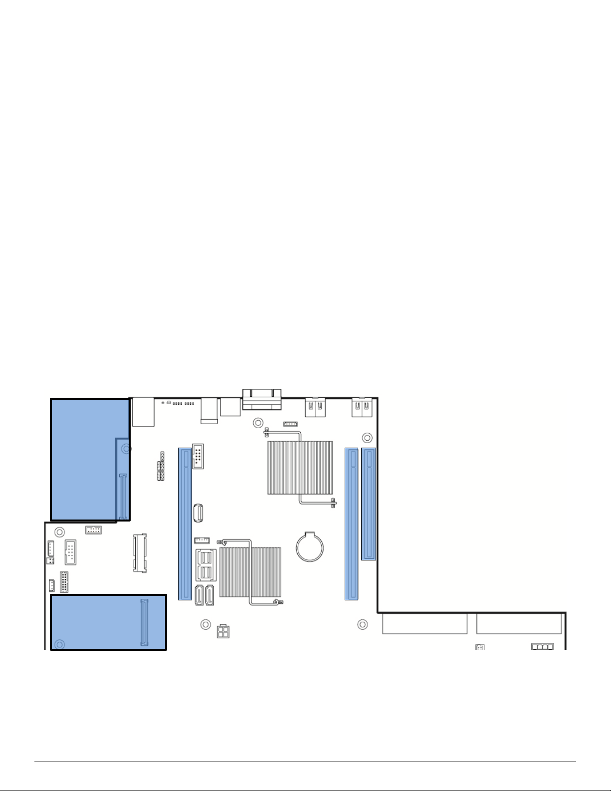
Intel® Server Board S2600WT TPS
Riser Slot #1
Riser Slot #2
Riser Slot #3
The PCI express* Port 3A of Intel® Xeon® Processor E5-2600 v3 Product Families can be configured to be a
transparent bridge or an NTB with x4/x8/x16 link width and Gen1/Gen2/Gen3 link speed. This NTB port
could be attached to another NTB port or PCI express* Root Port on another subsystem. NTB supports three
64bit BARs as configuration space or prefetchable memory windows that can access both 32bit and 64bit
address space through 64bit BARs.
There are 3 NTB supported configurations:
• NTB Port to NTB Port Based Connection (Back-to-Back)
• NTB Port to Root Port Based Connection – Symmetric Configuration. The NTB port on the first system
is connected to the root port of the second. The second system’s NTB port is connected to the root
port on the first system making this a fully symmetric configuration.
• NTB Port to Root Port Based Connection – Non-Symmetric Configuration. The root port on the first
system is connected to the NTB port of the second system. It is not necessary for the first system to
be an Intel® Xeon® Processor E5-2600 v3 Product Families system.
Note: When NTB is enabled, Spread Spectrum Clocking (SSC) is required to be disabled at each NTB link.
5.4 Add-in Card Support
The server board includes features for concurrent support of several add-in card types including: PCIe* addin cards via three riser card slots, Intel
®
and Intel
Integrated RAID Modules via a proprietary high density 80 pin connector. The following illustration
identifies the location of the onboard connector features and general board placement for add-in modules
and riser cards.
®
I/O module options via a proprietary high density 80 pin connector,
Intel® I/O
Module
Intel® Integrated
SAS / RAID Module
Figure 12. On-board Add-in Card Support
Revision 1.0 34
Page 49

Intel® Server Board S2600WT TPS
iPN - A2ULPCIXRISER2
iPN – A2UL8RISER2
iPN – A2UL16RISER2
iPN – F1UL16RISER2
(133MHz – Independent bus)
Port 2C
(x8 elec, x16 mech)
(133MHz - Independent bus)
(x8 elec, x16 mech)
(x8 elec, x8 mech)
(x8 elec, x8 mech)
(x8 elec, x8 mech)
iPN - A2ULPCIXRISER2
iPN – A2UL8RISER2
iPN – A2UL16RISER2
iPN – F1UL16RISER2
(133MHz – Independent bus)
Port 3C
(x8 elec, x16 mech)
5.4.1 Riser Card Support
The server board provides three riser card slots identified as: Riser Slot #1, Riser Slot #2, and Riser Slot #3.
Note: The riser card slots are specifically designed to support riser cards only. Attempting to install a
PCIe* add-in card directly into a riser card slot on the server board may damage the server board, the add-in
card, or both.
The PCIe* bus interface for each riser card slot is supported by each of the two installed processors. The
following tables provide the PCIe* bus routing for all supported risers cards.
Note: The bottom add-in card slot of the 2U 3-slot riser card and Riser Card Slots #2 and #3 on the server
board can only be used in dual processor configurations.
Table 9. Riser Card #1 - PCIe* Root Port Mapping
Riser Slot #1 – Riser Card Options
2U – PCI-X Riser Card
Top PCI-X Slot
CPU#1 – Port 3C
Middle PCI-X Slot
CPU #2 – Port 1B
(133MHz – Independent bus)
Bottom PCIe* Slot
CPU #1 – Port 3A
(x8 elec, x8 mech)
2U - 3-Slot Riser Card
Top PCIe* Slot
CPU #1 –
Middle PCIe* Slot
CPU #1 – Port 3A
(x8 elec, x16 mech)
Bottom PCIe* Slot
CPU #2 – Port 1A
(x8 elec, x8 mech)
Table 10. Riser Card #2 - PCIe* Root Port Mapping
Riser Slot #2 – Riser Card Options
2U – PCI-X Riser Card
Top PCI-X Slot
CPU #2 – Port 2C
Middle PCI-X Slot
CPU #2 – Port 3C
2U - 3-Slot Riser Card
Top PCIe* Slot
CPU #2 –
Middle PCIe* Slot
CPU #2 – Port 2A
2U - 2-Slot Riser Card
Top PCIe* Slot
CPU #1 – Port 3A
(x16 elec, x16 mech)
Bottom PCIe* Slot
CPU #2 – Port 1A
(x8 elec, x8 mech)
2U - 2-Slot Riser Card
Top PCIe* Slot
CPU #2 – Port 2A
(x16 elec, x16 mech)
1U - 1-Slot Riser Card
PCIe* Slot
CPU #1 – Port 3A
(x16 elec, x16 mech)
1U - 1-Slot Riser Card
Top PCIe* Slot
CPU #2 – Port 2A
(x16 elec, x16 mech)
Bottom PCIe* Slot
CPU #2 – Port 2A
35 Revision 1.0
Bottom PCIe* Slot
CPU #2 – Port 3C
Bottom PCIe* Slot
CPU #2 – Port 3C
Page 50
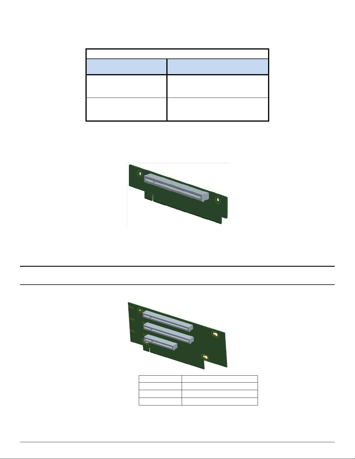
Intel® Server Board S2600WT TPS
Riser Slot #3 - Riser Card Options
iPN – A2UX8X4RISER
Top PCIe* Slot
(x4 elec, x8 mech)
Bottom PCIe* Slot
(x8 elec, x8 mech)
Slot #
Description
Table 11. Riser Slot #3 - PCIe* Root Port Mapping
2U - Low Profile Riser Card
CPU #2 – Port DMI 2
CPU #2 – Port 3A
Notes
PCIe* 2.0 Support Only
Available riser cards for Riser Slots #1 and #2 are common between the two slots.
1U – One PCIe* add-in card slot – PCIe* x16, x16 mechanical
Figure 13. 1U one slot PCIe* riser card (iPN – F1UL16RISER2)
Each riser card assembly has support for a single full height, ½ length PCIe* add-in card. However, riser card
#2 may be limited to ½ length, ½ height add-in cards if either of the two mini-SAS HD connectors on the
server board are used.
Note: Add-in cards that exceed the PCI specification for ½ length PCI add-in cards (167.65mm or 6.6in) may
interfere with other installed devices on the server board.
2U – Three PCIe* add-in card slots
Slot-1 (Top) PCIe* x8 elec, x16 mechanical
Slot-2 (Middle) PCIe* x8 elec, x16 mechanical
Slot-3 (Bottom) PCIe* x8 elec, x8 mechanical
Figure 14. 2U three PCIe* slot riser card (iPN – A2UL8RISER2)
Revision 1.0 36
Page 51

Intel® Server Board S2600WT TPS
Slot #
Description
Slot #
Description
Slot-1 (Top)
PCI-X 133 MHz
Each riser card assembly has support for up to two full height full length add-in cards (top and middle slots)
and one full height ½ length add-in card (bottom slot).
2U – Two PCIe* add-in card slots
Slot-1 (Top) PCIe* x16 elec, x16 mechanical
Slot-2 (Bottom) PCIe* x8 elec, x8 mechanical
Figure 15. 2U two PCIe* slot riser card (iPN – A2UL16RISER2)
Each riser card assembly has support for one full height full length add-in card (top slot) and one full height
½ length add-in card (bottom slot).
2U – Three add-in card slots( 2x PCI-X (133MHz) + 1x PCIe*) –
Note: Due to a mechanical interference, concurrent installation of the PCI-X Riser card in Riser Slot #1 and an
on-board SAS module is not supported.
Slot-2 (Middle) PCI-X 133 MHz
Slot-3 (Bottom) PCIe* x8 elec, x8 mechanical
37 Revision 1.0
Figure 16. 2U three PCIx/PCIe* slot riser (iPN - A2ULPCIXRISER2)
Page 52

Intel® Server Board S2600WT TPS
Slot #
Description
Slot-1 (Top)
PCIe* x4 elec, x8 mechanical (PCIe* 2.0 support only)
Riser Slot #3 is provided to support up to two additional PCIe* add-in card slots for 2U server configurations.
The available riser card option is designed to support low profile add-in cards only.
Figure 17. 2U two PCIe* slot (Low Profile) PCIe* Riser card (iPN – A2UX8X4RISER) – Riser Slot #3 compatible only
Slot-2 (Bottom) PCIe* x8 elec, x8 mechanical
5.4.2 I/O Module Support
To broaden the standard on-board feature set, the server board provides support for one of several
available Intel I/O Module options. The I/O module attaches to a high density 80-pin connector on the server
board labeled “IO_Module” and is supported by x8 PCIe* 3.0 signals from the IIO module of the CPU 1
processor.
Figure 18. Server Board Layout - I/O Module Connector
Revision 1.0 38
Page 53

Intel® Server Board S2600WT TPS
Description
Intel Product Code
Dual Port Intel® X540 10GbE I/O Module
AXX10GBTWLIOM
Single Port FDR InfiniBand* ConnectX*-3 I/O Module
AXX1FDRIBIOM
Dual Ports FDR InfiniBand* ConnectX*-3 I/O Module
AXX2FDRIBIOM
Dual Port 40GbE I/O Module
AXX2P40FRTIOM
Supported I/O modules include:
Table 12. Supported Intel® I/O Module Options
Quad Port Intel® I350 GbE I/O Module AXX4P1GBPWLIOM
Dual Port Intel® 82599 10GbE I/O Module AXX10GBNIAIOM
Single port 40GbE I/O Module AXX1P40FRTIOM
5.4.3 Intel
®
Integrated RAID Option
The server board provides support for Intel® Integrated RAID modules. These optional modules attach to a
high density 80-pin connector labeled “SAS Module” on the server board and are supported by x8 PCIe* 3.0
signals from the IIO module of the CPU 1 processor.
Figure 19. Server Board Layout – Intel® Integrated RAID Module Option Placement
®
Please visit the Intel
Server Configurator Tool at the following website for a list of supported Intel®
Integrated RAID options:
https://serverconfigurator.intel.com
39 Revision 1.0
Page 54

Intel® Server Board S2600WT TPS
5.5 Serial ATA (SATA) Support
The server board utilizes two chipset embedded AHCI SATA controllers, identified as SATA and sSATA,
providing for up to ten 6 Gb/sec Serial ATA (SATA) ports.
The AHCI SATA controller provides support for up to six SATA ports on the server board
• Four SATA ports from the Mini-SAS HD (SFF-8643) connector labeled “SATA Ports 0-3” on the server
board
• Two SATA ports accessed via two white single port connectors labeled “SATA-4” and “SATA-5” on
the server board
The AHCI sSATA controller provides support for up to four SATA ports on the server board
• Four SATA ports from the Mini-SAS HD (SFF-8643) connector labeled “sSATA Ports 0-3” on the
server board
The following diagram identifies the location of all on-board SATA features.
Figure 20. Onboard SATA Features
The SATA controller and the sSATA controller can be independently enabled and disabled and configured
through the <F2> BIOS Setup Utility under the “Mass Storage Controller Configuration” menu screen. The
following table identifies supported setup options.
Revision 1.0 40
Page 55

Intel® Server Board S2600WT TPS
SATA Controller
sSATA Controller
Supported
Enhanced
AHCI
Yes
Enhanced
Enhanced
Yes
Enhanced
Disabled
Yes
Enhanced
RSTe
Yes
Enhanced
ESRT2
Yes
Disabled
RSTe
Yes
RSTe
AHCI
Yes
RSTe
Enhanced
Yes
RSTe
Disabled
Yes
RSTe
RSTe
Yes
ESRT2
RSTe
No
ESRT2
ESRT2
Yes
AHCI / RAID
AHCI / RAID
Collapses a DMA Setup then DMA Activate sequence
Allows for device detection without power being
Provides a recovery from a loss of signal or
6 Gb/s Transfer Rate
Capable of data transfers up to 6 Gb/s
Supported
Supported
A mechanism for a device to send a notification to the
Capability for the host controller or device to request
Table 13. SATA and sSATA Controller BIOS Utility Setup Options
AHCI AHCI Yes
AHCI Enhanced Yes
AHCI Disabled Yes
AHCI RSTe Yes
AHCI ESRT2 Microsoft* Windows Only
Disabled AHCI Yes
Disabled Enhanced Yes
Disabled Disabled Yes
Disabled ESRT2 Yes
Feature Description
Native Command Queuing (NCQ)
Auto Activate for DMA
Hot Plug Support
Asynchronous Signal Recovery
RSTe ESRT2 No
ESRT2 AHCI Microsoft* Windows Only
ESRT2 Enhanced Yes
ESRT2 Disabled Yes
Table 14. SATA and sSATA Controller Feature Support
Allows the device to reorder commands for more
efficient data transfers
into a DMA Setup only
applied and ability to connect and disconnect devices
without prior notification to the system
establishing communication after hot plug
Disabled
N/A Supported
N/A Supported
N/A Supported
N/A Supported
Enabled
ATAPI Asynchronous Notification
Host & Link Initiated Power Management
Staggered Spin-Up
41 Revision 1.0
host that the device requires attention
Partial and Slumber interface power states
Enables the host the ability to spin up hard drives
sequentially to prevent power load problems on boot
N/A Supported
N/A Supported
Supported Supported
Page 56

Intel® Server Board S2600WT TPS
AHCI / RAID
AHCI / RAID
Reduces interrupt and completion overhead by
Feature Description
Command Completion Coalescing
allowing a specified number of commands to
complete and then generating an interrupt to process
the commands
Disabled
Supported N/A
Enabled
5.5.1 Staggered Disk Spin-Up
Because of the high density of disk drives that can be attached to the C612 Onboard AHCI SATA Controller
and the sSATA Contoller, the combined startup power demand surge for all drives at once can be much
higher than the normal running power requirements and could require a much larger power supply for
startup than for normal operations.
In order to mitigate this and lessen the peak power demand during system startup, both the AHCI SATA
Controller and the sSATA Controller implement a Staggered Spin-Up capability for the attached drives. This
means that the drives are started up separately, with a certain delay between disk drives starting.
For the Onboard SATA Controller, Staggered Spin-Up is an option – AHCI HDD Staggered Spin-Up – in the
Setup Mass Storage Controller Configuration screen found in the <F2> BIOS Setup Utility.
5.6 Embedded SATA SW-RAID support
The server board has embedded support for two SATA SW-RAID options:
®
Intel
Intel
Using the <F2> BIOS Setup Utility, accessed during system POST, options are available to enable/disable SW
RAID, and select which embedded software RAID option to use.
Note: RAID partitions created using either RSTe or ESRT2 cannot span across the two embedded SATA
controllers. Only drives attached to a common SATA controller can be included in a RAID partition.
5.6.1 Intel
Intel® Rapid Storage Technology offers several options for RAID (Redundant Array of Independent Disks) to
meet the needs of the end user. AHCI support provides higher performance and alleviates disk bottlenecks
by taking advantage of the independent DMA engines that each SATA port offers in the chipset.
RAID Level 0 – Non-redundant striping of drive volumes with performance scaling of up to 6 drives,
Data security is offered through RAID Level 1, which performs mirroring.
RAID Level 10 provides high levels of storage performance with data protection, combining the fault-
RAID Level 5 provides highly efficient storage while maintaining fault-tolerance on 3 or more drives.
Rapid Storage Technology (RSTe) 4.0
®
Embedded Server RAID Technology 2 (ESRT2) based on LSI* MegaRAID SW RAID technology
®
Rapid Storage Technology (RSTe) 4.0
enabling higher throughput for data intensive applications such as video editing.
tolerance of RAID Level 1 with the performance of RAID Level 0. By striping RAID Level 1 segments,
high I/O rates can be achieved on systems that require both performance and fault-tolerance. RAID
Level 10 requires 4 hard drives, and provides the capacity of two drives.
By striping parity, and rotating it across all disks, fault tolerance of any single drive is achieved while
only consuming 1 drive worth of capacity. That is, a 3 drive RAID 5 has the capacity of 2 drives, or a 4
drive RAID 5 has the capacity of 3 drives. RAID 5 has high read transaction rates, with a medium write
Revision 1.0 42
Page 57

Intel® Server Board S2600WT TPS
rate. RAID 5 is well suited for applications that require high amounts of storage while maintaining
fault tolerance.
Note: RAID configurations cannot span across the two embedded AHCI SATA controllers.
By using Intel® RSTe, there is no loss of PCI resources (request/grant pair) or add-in card slot. Intel® RSTe
functionality requires the following:
The SW-RAID option must be enable in <F2> BIOS Setup
®
Intel
Intel
RSTe option must be selected in <F2> BIOS Setup
®
RSTe drivers must be loaded for the installed operating system
At least two SATA drives needed to support RAID levels 0 or 1
At least three SATA drives needed to support RAID levels 5 or 10
®
With Intel
RSTe SW-RAID enabled, the following features are made available:
A boot-time, pre-operating system environment, text mode user interface that allows the user to
manage the RAID configuration on the system. Its feature set is kept simple to keep size to a
minimum, but allows the user to create and delete RAID volumes and select recovery options when
problems occur. The user interface can be accessed by pressing the <CTRL-I> keys during system
POST.
Provides boot support when using a RAID volume as a boot disk. It does this by providing Int13
services when a RAID volume needs to be accessed by MS-DOS applications (such as NTLDR) and by
exporting the RAID volumes to the System BIOS for selection in the boot order
At each boot up, provides the user with a status of the RAID volumes
5.6.2 Intel
®
Embedded Server RAID Technology 2 (ESRT2)
Features of ESRT2 include the following:
Based on LSI* MegaRAID Software Stack
Software RAID with system providing memory and CPU utilization
RAID Level 0 - Non-redundant striping of drive volumes with performance scaling up to 6 drives,
enabling higher throughput for data intensive applications such as video editing.
Data security is offered through RAID Level 1, which performs mirroring.
RAID Level 10 provides high levels of storage performance with data protection, combining the fault-
tolerance of RAID Level 1 with the performance of RAID Level 0. By striping RAID Level 1 segments,
high I/O rates can be achieved on systems that require both performance and fault-tolerance. RAID
Level 10 requires 4 hard drives, and provides the capacity of two drives
Optional support for RAID Level 5
o Enabled with the addition of an optionally installed ESRT2 SATA RAID 5 Upgrade Key (iPN -
RKSATA4R5)
o RAID Level 5 provides highly efficient storage while maintaining fault-tolerance on 3 or more
drives. By striping parity, and rotating it across all disks, fault tolerance of any single drive is
achieved while only consuming 1 drive worth of capacity. That is, a 3 drive RAID 5 has the
capacity of 2 drives, or a 4 drive RAID 5 has the capacity of 3 drives. RAID 5 has high read
transaction rates, with a medium write rate. RAID 5 is well suited for applications that require
high amounts of storage while maintaining fault tolerance
43 Revision 1.0
Page 58

Intel® Server Board S2600WT TPS
Figure 21. SATA RAID 5 Upgrade Key
Maximum drive support = 6 (Maximum on-board SATA port support)
Open Source Compliance = Binary Driver (includes Partial Source files) or Open Source using MDRAID
layer in Linux*.
Note: RAID configurations cannot span across the two embedded AHCI SATA controllers.
5.7 Network Interface
On the back edge of the server board are three RJ45 networking ports; “NIC #1”, “NIC #2”, and a Dedicated
Management Port.
Figure 22. Network Interface Connectors
Each ethernet port drives two LEDs located on each network interface connector. The LED at the left of the
connector is the link/activity LED and indicates network connection when on, and transmit/receive activity
when blinking.
Revision 1.0 44
Page 59

Intel® Server Board S2600WT TPS
On
LAN link is established
Blinking
Transmit / Receive Activity
Off
Lowest supported data rate
Amber
On
Mid-range supported data rate
The LED at the right of the connector indicates link speed as defined in the following table.
LED Color LED State NIC State
Off LAN link not established
Left Green
Right
Green On Highest supported data rate
Figure 23. External RJ45 NIC Port LED Definition
NOTE: Lowest, Mid-range, and Highest supported data rate is dependent on which onboard networking
controller option is present. See section 5.7.1 for details on available onboard network controller options.
5.7.1 Intel® Ethernet Controller Options
The server board is offered with the following Intel® Ethernet Controller options:
• Intel
• Intel
®
Ethernet Controller X540 10 GbE (Server board product code - S2600WTT)
®
Ethernet Controller I350 1 GbE (Server board product code - S2600WT2)
Refer to the respective product data sheets for a complete list of supported Ethernet Controller features.
5.7.2 Factory Programmed MAC Address Assignments
Depending on which onboard ethernet controller is present, the server board may have 5 or 7 MAC
addresses programmed at the factory. MAC addresses are assigned as follows:
• NIC # 1 MAC address = Base #
• NIC # 2 MAC address = Base # + 1
• BMC LAN channel 0 MAC address = Base # + 2
• BMC LAN channel 1 MAC address = Base # + 3
• Dedicated On-board Management Port MAC address = Base # + 4
The following MAC address assignments are used for FCoE support on server boards with an on-board Intel
Ethernet Controller X540:
• NIC #1 SAN MAC address = Base # + 5
• NIC #2 SAN MAC address = Base # + 6
The base MAC address will be printed on a label and affixed to the server board and/or Intel server system.
Factory programmed MAC addresses can also be viewed in the <F2> BIOS Setup Utility.
®
5.8 Video Support
The graphics controller of the integrated baseboard management controller provides support for the
following features as implemented on the server board:
Integrated Graphics Core with 2D Hardware accelerator
DDR-3 memory interface with 16 MB of memory allocated and reported for graphics memory
High speed Integrated 24-bit RAMDAC
Single lane PCI-Express host interface running at Gen 1 speed
45 Revision 1.0
Page 60

Intel® Server Board S2600WT TPS
8
16
24
32
1024x768
X X X X 1152x864
X X X
X
1280x1024
X X X X 1600x1200**
X X
The integrated video controller supports all standard IBM* VGA modes. The following table shows the 2D
modes supported for both CRT and LCD:
Table 15. Video Modes
2D Mode 2D Video Mode Support
bpp
bpp
640x480 X X X X
800x600 X X X X
bpp
bpp
** Video resolutions at 1600x1200 and higher are only supported through the external video connector
located on the rear I/O section of the server board. Utilizing the optional front panel video connector may
result in lower video resolutions.
The server board provides two onboard video interfaces. The primary video interface is accessed using a
standard 15-pin VGA connector found on the back edge of the server board. In addition, video signals are
routed to a 14-pin header labeled “FP_Video”, allowing for the option of cabling to a front panel video
connector. Attaching a monitor to the front panel video connector will disable the primary external video
connector on the back edge of the board.
5.8.1 Dual Video and Add-In Video Adapters
There are enable/disable options in the <F2> BIOS Setup PCI Configuration screen for “Add-in Video
Adapter” and “Onboard Video”.
• When Onboard Video is Enabled, and Add-in Video Adapter is also Enabled, then both video displays
can be active. The onboard video is still the primary console and active during BIOS POST; the add-in
video adapter would be active under an OS environment with the video driver support.
• When Onboard Video is Enabled, and Add-in Video Adapter is Disabled, then only the onboard video
would be active.
• When Onboard Video is Disabled, and Add-in Video Adapter is Enabled, then only the add-in video
adapter would be active.
Configurations with add-in video cards can get more complicated on server boards that have two or more
CPU sockets. Some multi-socket boards have PCIe* slots capable of hosting an add-in video card which are
attached to the IIOs of CPU sockets other than CPU Socket 1. However, only one CPU Socket can be
designated as “Legacy VGA Socket” as required in POST.
To provide for this, there is another PCI Configuration option to control “Legacy VGA Socket”. The rules for
this are:
• This option appears only on boards which have the possibility of an add-in video adapter in a PCIe*
slot on a CPU socket other than socket 1.
Revision 1.0 46
• When present, the option is grayed out and unavailable unless an add-in video card is actually
installed in a PCIe* slot connected to the other socket.
Page 61

Intel® Server Board S2600WT TPS
• Because the Onboard Video is “hardwired” to CPU Socket 1, whenever Legacy VGA Socket is set to a
CPU Socket other than Socket 1, that disables both Onboard Video ports.
5.8.1.1 Dual Monitor Video
The BIOS supports single and dual video on the S2600 family of Server Board when add-in video adapters
are installed. Although there is no enable/disable option in BIOS screen for Dual Video, it works when both
“Onboard video” and “Add-in Video Adapter” are enabled.
In the single video mode, the onboard video controller or the add-in video adapter is detected during the
POST. In the dual video mode, the onboard video controller is enabled and is the primary video device while
the add-in video adapter is allocated resources and is considered the secondary video device.
5.8.1.2 Configuration Cases – Multi-CPU Socket Boards and Add-In Video Adapters
Because this combination of CPU Socket and PCIe* topology is complicated and somewhat confusing, the
following set of “Configuration Cases” was generated to clarify the design.
• When there are no add-in video cards installed...
Case 1: Onboard Video only active display.
Onboard Video = Enabled (grayout, can't change)
Legacy VGA Socket = CPU Socket 1 (grayout, can't change)
Add-in Video Adapter = Disabled (grayout, can't change)
• When there is one add-in video card connected to CPU Socket 1...
Case 2: Onboard video active display, add-in video doesn't display.
Onboard Video = Enabled
Legacy VGA Socket = CPU Socket 1 (grayout, can't change)
Add-in Video Adapter = Disabled
Case 3: Add-in video active display, onboard video doesn't display.
Onboard Video = Disabled,
Legacy VGA Socket = CPU Socket 1 (grayout, can't change)
Add-in Video Adapter = Enabled
Case 4: Both onboard video and add-in video are active displays. But only onboard could be the
active display during BIOS POST (Dual Monitor).
Onboard Video = Enabled
Legacy VGA Socket = CPU Socket 1 (grayout, can't change)
Add-in Video Adapter = Enabled
• When there is one add-in video card connected to CPU Socket 2...
Case 5: Onboard video active display, add-in doesn't display.
Onboard Video = Enabled
Legacy VGA Socket = CPU Socket 1
Add-in Video Adapter = Disabled (grayout, can't change)
Case 6: Add-in video active display, onboard video doesn't display.
Onboard Video = Disabled (grayout, can't change)
Legacy VGA Socket = CPU Socket 2
Add-in Video Adapter = Enabled (grayout, can't change)
47 Revision 1.0
Page 62

Intel® Server Board S2600WT TPS
Memory Mapped I/O above 4 GB
Enabled / Disabled
Add-in Video Adapter
Enabled / Disabled
Onboard Video
Enabled / Disabled
Legacy VGA Socket
CPU Socket 1 / CPU Socket 2
NIC Configuration
• When there are add-in video cards connected to both CPU Socket 1 & 2...
Case 7: Onboard video active display, add-in video on Socket 1 and Add-in video on Socket 2 don’t
actively display.
Onboard Video = Enabled
Legacy VGA Socket = CPU Socket 1
Add-in Video Adapter = Disabled
Case 8: Add-in video on Socket 1 active display, onboard video and Add-in video on Socket 2 don’t
actively display.
Onboard Video = Disabled
Legacy VGA Socket = CPU Socket 1
Add-in Video Adapter = Enabled
Case 9: Both onboard video active and CPU Socket 1 add-in video active display. But only onboard
could actively display during BIOS POST.
Onboard Video = Enabled
Legacy VGA Socket = CPU Socket 1
Add-in Video Adapter = Enabled
Case 10: Only CPU Socket 2 add-in video active display, neither onboard video nor CPU Socket 1
add-in video display.
Onboard Video = Disabled (grayout, can't change)
Legacy VGA Socket = CPU Socket 2
Add-in Video Adapte = Enabled (grayout, can't change)
5.8.2 Setting Video Configuration Options using the BIOS Setup Utility
PCI Configuration
Auto/1G/2G/4G/8G/16G/32G/64G/128G/256G/
Memory Mapped I/O Size
PCIe* Port Oprom Control
Processor PCIe* Link Speed
512G/ 1024G
Revision 1.0 48
Figure 24. BIOS Setup Utility - Video Configuration Options
Page 63

Intel® Server Board S2600WT TPS
1. Add-in Video Adapter
Option Values: Enabled
Disabled
Help Text:
If enabled, the Add-in video adapter works as primary video device during POST if installed. If disabled, the
on-board video controller becomes the primary video device.
Comments: This option must be enabled to use an add-in card as a primary POST Legacy Video device.
If there is no add-in video card in any PCIe* slot connected to CPU Socket 1 with the Legacy VGA Socket
option set to CPU Socket 1, this option is set to Disabled and grayed out and unavailable.
If there is no add-in video card in any PCIe* slot connected to CPU Socket 2 with the Legacy VGA Socket
option set to CPU Socket 2, this option is set to Disabled and grayed out and unavailable.
If the Legacy VGA Socket option is set to CPU Socket 1 with both Add-in Video Adapter and Onboard Video
Enabled, the onboard video device works as primary video device while add-in video adapter as secondary.
2. Onboard Video
Option Values: Enabled
Disabled
Help Text:
On-board video controller.
Warning: System video is completely disabled if this option is disabled and an add-in video adapter is not
installed.
Comments: When disabled, the system requires an add-in video card for the video to be seen. When there
is no add-in video card installed, Onboard Video is set to Enabled and grayed out so it cannot be changed.
If there is an add-in video card installed in a PCIe* slot connected to CPU Socket 1, and the Legacy VGA
Socket option is set to CPU Socket 1, then this Onboard Video option is available to be set and default as
Disabled.
If there is an add-in video card installed on a PCIe* slot connected to CPU Socket 2, and the Legacy VGA
Socket option is set to CPU Socket 2, this option is grayed out and unavailable, with a value set to Disabled.
This is because the Onboard Video is connected to CPU Socket 1, and is not functional when CPU Socket 2 is
the active path for video. When Legacy VGA Socket is set back to CPU Socket 1, this option becomes
available again and is set to its default value of Enabled.
3. Legacy VGA Socket
Option Values: CPU Socket 1
CPU Socket 2
Help Text:
Determines whether Legacy VGA video output is enabled for PCIe* slots attached to Processor Socket 1 or 2.
Socket 1 is the default.
Comments: This option is necessary when using an add-in video card on a PCIe* slot attached to CPU
Socket 2, due to a limitation of the processor IIO. The Legacy video device can be connected through either
socket but there is a setting that must be set on only one of the two. This option allows the switch to using a
video card in a slot connected to CPU Socket 2.
This option does not appear unless the BIOS is running on a board which has one processor installed on CPU
Socket 2 and can potentially have a video card installed in a PCIe* slot connected to CPU Socket 2.
This option is grayed out as unavailable and set to CPU Socket 1 unless there is a processor installed on CPU
Socket 2 and a video card installed in a PCIe* slot connected to CPU Socket 2. When this option is active and
is set to CPU Socket 2, then both Onboard Video and Dual Monitor Video are set to Disabled and grayed out
as unavailable. This is because the Onboard Video is a PCIe* device connected to CPU Socket 1, and is
unavailable when the Legacy VGA Socket is set to Socket 2.
49 Revision 1.0
Page 64

Intel® Server Board S2600WT TPS
C612
Dual Port Front
USB 2.0 (0,1,2)
USB 2.0 & USB 3.0 I/O
(USB Port #s)
Integrated
BMC
USB 2.0 (4,12)
* Dual Port
USB 2.0 (10,13)
connector
5.9 USB Support
The server board provides support for both USB 2.0 (up to 480 Mb/sec) and USB 3.0 (up to 5 Gb/sec).
Internal Mount
LP eUSB SSD
(Option)
USB 2.0 (8)
Internal
Mount
Type-A
USB 2.0 (3)
Intel®
Chipset
Stacked Triple
Panel Header
USB 2.0 (5,6)
Figure 25. Onboard USB Port Support
Front Panel
Header
USB 3.0 (1,4)
Port Back Panel
USB 3.0 (2,3,5)
* Note: Due to signal strength limits associated with USB 3.0 ports cabled to a front panel, some marginally
compliant USB 3.0 devices may not be supported from these ports. In addition, server systems based on the
Intel® Server Board S2600WT cannot be USB 3.0 certified with USB 3.0 ports cabled to a front panel.
5.9.1 Low Profile eUSB SSD Support
The server board provides support for a low profile eUSB SSD storage device. A 2mm 2x5-pin connector
labeled “eUSB SSD” near the rear I/O section of the server board is used to connect this small flash storage
device to the system.
LP eUSB SSD
Revision 1.0 50
Figure 26. Low Profile eUSB SSD Support
Page 65

Intel® Server Board S2600WT TPS
Signal Description
Pin#
RTS
1
DTR
2
SOUT
3
GROUND
4
RI
5
SIN 6 DCD or DSR
7**
CTS
8
Serial A
eUSB SSD features include:
• 2 wire small form factor Universal Serial Bus 2.0 (Hi-Speed USB) interface to host
• Read Speed up to 35 MB/s and write Speed up to 24 MB/s.
• Capacity range from 256 MB to 32 GB.
• Support USB Mass Storage Class requirements for Boot capability.
Please visit the Intel
®
Server Configurator Tool at the following website for a list of supported eUSB SSD
devices.
https://serverconfigurator.intel.com
5.10 Serial Ports
The server board has support for two serial ports, Serial A and Serial B. Serial-A is an external RJ45 type
connector located on the back edge of the server board.
The Serial A connector has the following pin-out configuration.
51 Revision 1.0
Table 16. Serial A Connector Pin-out
Page 66

Intel® Server Board S2600WT TPS
Signal Description
Pin#
Pin#
Signal Description
DCD
1 2 DSR
SIN 3 4
RTS
SOUT
5 6 CTS
DTR
7 8 RI
GROUND
9 KEY
Serial B
DH-10
** Pin 7 of the RJ45 Serial A connector is configurable to support either a DSR (Default) signal or a DCD
signal. Pin 7 signals are changed by moving the jumper on the jumper block labeled “J4A4”, located behind
the connector, from pins 1-2 (default) to pins 2-3.
Serial-A configuration jumper block (J4A4) setting:
Serial-B is an internal 10-pin DH-10 connector labeled “Serial_B”.
The Serial B connector has the following pin-out.
Revision 1.0 52
Table 17. Serial-B Connector Pin-out
Page 67

Intel® Server Board S2600WT TPS
User Password Status
<Installed/Not Installed>
Set Administrator Password
[123aBcDeFgH$#@]
Front Panel Lockout
Enabled/Disabled
No Operation/Turn On/Turn Off/Clear
Ownership
6. System Security
The server board supports a variety of system security options designed to prevent unauthorized system
access or tampering of server settings. System security options supported include:
• Password Protection
• Front Panel Lockout
• Trusted Platform Module (TPM) support
• Intel
6.1 BIOS Setup Utility Security Options Menu
The <F2> BIOS Setup Utility, accessed during POST, includes a Security tab where options to configure
passwords, front panel lockout, and TPM settings, can be found.
®
Trusted Execution Technology
Security
Administrator Password Status <Installed/Not Installed>
Set User Password [123aBcDeFgH$#@]
Power On Password Enabled/Disabled
TPM State <Displays current TPM Device State>
TPM Administrative Control
6.1.1 Password Setup
The BIOS uses passwords to prevent unauthorized access to the server. Passwords can restrict entry to the
BIOS Setup utility, restrict use of the Boot Device popup menu during POST, suppress automatic USB device
re-ordering, and prevent unauthorized system power on. It is strongly recommended that an Administrator
Password be set. A system with no Administrator password set allows anyone who has access to the server
to change BIOS settings.
An Administrator password must be set in order to set the User password.
The maximum length of a password is 14 characters and can be made up of a combination of alphanumeric
(a-z, A-Z, 0-9) characters and any of the following special characters:
! @ # $ % ^ & * ( ) - _ + = ?
Passwords are case sensitive.
53 Revision 1.0
Page 68

Intel® Server Board S2600WT TPS
The Administrator and User passwords must be different from each other. An error message will be
displayed and a different password must be entered if there is an attempt to enter the same password for
both. The use of “Strong Passwords” is encouraged, but not required. In order to meet the criteria for a
strong password, the password entered must be at least 8 characters in length, and must include at least one
each of alphabetic, numeric, and special characters. If a weak password is entered, a warning message will be
displayed, and the weak password will be accepted. Once set, a password can be cleared by changing it to a
null string. This requires the Administrator password, and must be done through BIOS Setup. Clearing the
Administrator password will also clear the User password. Passwords can also be cleared by using the
Password Clear jumper on the server board. See Chapter 10 – Reset and Recovery Jumpers.
Resetting the BIOS configuration settings to default values (by any method) has no effect on the
Administrator and User passwords.
As a security measure, if a User or Administrator enters an incorrect password three times in a row during the
boot sequence, the system is placed into a halt state. A system reset is required to exit out of the halt state.
This feature makes it more difficult to guess or break a password.
In addition, on the next successful reboot, the Error Manager displays a Major Error code 0048, which also
logs a SEL event to alert the authorized user or administrator that a password access failure has occurred.
6.1.2 System Administrator Password Rights
When the correct Administrator password is entered when prompted, the user has the ability to perform the
following:
• Access the <F2> BIOS Setup Utility
• Configure all BIOS setup options in the <F2> BIOS Setup Utility
• Clear both the Administrator and User passwords
• Access the <F6> Boot Menu during POST
• If the Power On Password function is enabled in BIOS Setup, the BIOS will halt early in POST to
request a password (Administrator or User) before continuing POST.
6.1.3 Authorized System User Password Rights and Restrictions
When the correct User password is entered, the user has the ability to perform the following:
• Access the <F2> BIOS Setup Utility
• View, but not change, any BIOS Setup options in the <F2> BIOS Setup Utility
• Modify System Time and Date in the BIOS Setup Utility
• If the Power On Password function is enabled in BIOS Setup, the BIOS will halt early in POST to
request a password (Administrator or User) before continuing POST
Configuring an Administrator password imposes restrictions on booting the system, and configures most
Setup fields to read-only if the Administrator password is not provided. The F6 Boot popup menu requires
the Administrator password to function, and the USB Reordering is suppressed as long as the Administrator
password is enabled. Users are restricted from booting in anything other than the Boot Order defined
in Setup by an Administrator.
6.1.4 Front Panel Lockout
If enabled in BIOS setup, this option disables the following front panel features:
• The OFF function of the Power button
• System Reset button
• NMI Diagnostic Interrupt button
If [Enabled] is selected, system power off and reset must be controlled via a system management interface.
Revision 1.0 54
Page 69

Intel® Server Board S2600WT TPS
6.2 Trusted Platform Module (TPM) Support
The server board has the option to support a Trusted Platform Module (TPM) which plugs into a high density
14-pin connector labeled “TPM”.
A TPM is a hardware-based security device that addresses the growing concern on boot process integrity
and offers better data protection. TPM protects the system start-up process by ensuring it is tamper-free
before releasing system control to the operating system. A TPM device provides secured storage to store
data, such as security keys and passwords. In addition, a TPM device has encryption and hash functions. The
server board implements TPM as per TPM PC Client specifications revision 1.2 by the Trusted Computing
Group (TCG).
A TPM device is secured from external software attacks and physical theft. A pre-boot environment, such as
the BIOS and operating system loader, uses the TPM to collect and store unique measurements from
multiple factors within the boot process to create a system fingerprint. This unique fingerprint remains the
same unless the pre-boot environment is tampered with. Therefore, it is used to compare to future
measurements to verify the integrity of the boot process.
After the system BIOS completes the measurement of its boot process, it hands off control to the operating
system loader and in turn to the operating system. If the operating system is TPM-enabled, it compares the
BIOS TPM measurements to those of previous boots to make sure the system was not tampered with before
continuing the operating system boot process. Once the operating system is in operation, it optionally uses
TPM to provide additional system and data security.
6.2.1 TPM security BIOS
The BIOS TPM support conforms to the TPM PC Client Implementation Specification for Conventional BIOS,
the TPM Interface Specification, and the Microsoft Windows BitLocker* Requirements. The role of the BIOS
for TPM security includes the following:
Measures and stores the boot process in the TPM microcontroller to allow a TPM enabled operating
system to verify system boot integrity.
Produces EFI and legacy interfaces to a TPM-enabled operating system for using TPM.
Produces ACPI TPM device and methods to allow a TPM-enabled operating system to send TPM
administrative command requests to the BIOS.
55 Revision 1.0
Page 70

Intel® Server Board S2600WT TPS
Verifies operator physical presence. Confirms and executes operating system TPM administrative
command requests.
Provides BIOS Setup options to change TPM security states and to clear TPM ownership.
For additional details, refer to the TCG PC Client Specific Implementation Specification, the TCG PC Client
Specific Physical Presence Interface Specification, and the Microsoft BitLocker* Requirement documents.
6.2.2 Physical Presence
Administrative operations to the TPM require TPM ownership or physical presence indication by the
operator to confirm the execution of administrative operations. The BIOS implements the operator presence
indication by verifying the setup Administrator password.
A TPM administrative sequence invoked from the operating system proceeds as follows:
1. User makes a TPM administrative request through the operating system’s security software.
2. The operating system requests the BIOS to execute the TPM administrative command through TPM ACPI
methods and then resets the system.
The BIOS verifies the physical presence and confirms the command with the operator.
3.
he BIOS executes TPM administrative command(s), inhibits BIOS Setup entry and boots directly to the
4. T
operating system which requested the TPM command(s).
6.2.3 TPM Security Setup Options
The BIOS TPM Setup allows the operator to view the current TPM state and to carry out rudimentary TPM
administrative operations. Performing TPM administrative options through the BIOS setup requires TPM
physical presence verification. TPM administrative options are only shown in the Security Menu screen when
a TPM is physically installed on the board.
Using BIOS TPM Setup, the operator can turn ON or OFF TPM functionality and clear the TPM ownership
contents. After the requested TPM BIOS Setup operation is carried out, the option reverts to No Operation.
The BIOS TPM Setup also displays the current state of the TPM, whether TPM is enabled or disabled and
activated or deactivated. Note that while using TPM, a TPM-enabled operating system or application may
change the TPM state independent of the BIOS setup. When an operating system modifies the TPM state, the
BIOS Setup displays the updated TPM state.
The BIOS Setup TPM Clear option allows the operator to clear the TPM ownership key and allows the
operator to take control of the system with TPM. You use this option to clear security settings for a newly
initialized system or to clear a system for which the TPM ownership security key was lost.
Revision 1.0 56
Page 71

Intel® Server Board S2600WT TPS
TPM Setup Options using the BIOS Setup Utility
Table 18. TPM Setup Utility – Security Configuration Screen Fields
Setup Item Options Help Text Comments
TPM State Enabled and Activated
Enabled and Deactivated
Disabled and Activated
Disabled and Deactivated
TPM
Administrative
Control
No Operation
Turn On
Turn Off
Clear Ownership
Information only.
Shows the current TPM device state.
A disabled TPM device will not execute
commands that use TPM functions and
TPM security operations will not be
available.
An enabled and deactivated TPM is in
the same state as a disabled TPM except
setting of TPM ownership is allowed if
not present already.
An enabled and activated TPM executes
all commands that use TPM functions
and TPM security operations will be
available.
[No Operation] - No changes to current
state.
[Turn On] - Enables and activates TPM.
[Turn Off] - Disables and deactivates TPM.
[Clear Ownership] - Removes the TPM
ownership authentication and returns the
TPM to a factory default state.
Note: The BIOS setting returns to [No
Operation] on every boot cycle by default.
Any Administrative Control operation
selected will require the system to
perform a Hard Reset in order to
become effective.
6.3 Intel
®
Trusted Execution Technology
The Intel® Xeon® Processor E5-4600/2600/2400/1600 v3 Product Families support Intel® Trusted Execution
®
Technology (Intel
based attacks, Intel
processor, chipset and other platform components. When used in conjunction with Intel
Technology, Intel
TXT), which is a robust security environment. Designed to help protect against software-
®
Trusted Execution Technology integrates new security features and capabilities into the
®
Virtualization
®
Trusted Execution Technology provides hardware-rooted trust for your virtual
applications.
This hardware-rooted security provides a general-purpose, safer computing environment capable of running
a wide variety of operating systems and applications to increase the confidentiality and integrity of sensitive
information without compromising the usability of the platform.
®
Trusted Execution Technology requires a computer system with Intel® Virtualization Technology
Intel
enabled (both VT-x and VT-d), an Intel
Authenticated Code Modules, and an Intel
®
Trusted Execution Technology-enabled processor, chipset and BIOS,
®
Trusted Execution Technology compatible measured launched
environment (MLE). The MLE could consist of a virtual machine monitor, an OS or an application. In addition,
®
Trusted Execution Technology requires the system to include a TPM v1.2, as defined by the Trusted
Intel
Computing Group TPM PC Client Specifications, Revision 1.2.
57 Revision 1.0
Page 72

Intel® Server Board S2600WT TPS
When available, Intel Trusted Execution Technology can be enabled or disabled in the processor from a BIOS
®
Setup option. For general information about Intel
TXT, visit the Intel® Trusted Execution Technology website
http://www.intel.com/technology/security/
7. Platform Management
Platform management is supported by several hardware and software components integrated on the server
board that work together to support the following:
Control systems functions – power system, ACPI, system reset control, system initialization, front
panel interface, system event log
Monitor various board and system sensors, regulate platform thermals and performance in order to
maintain (when possible) server functionality in the event of component failure and/or
environmentally stressed conditions
Monitor and report system health
Provide an interface for Server Management Software applications
This chapter provides a high level overview of the platform management features and functionality
implemented on the server board.
®
The Intel
BIOS External Product Specification (EPS) for Intel
2600 v3 product families should be referenced for more in-depth and design level platform management
information.
Server System BMC Firmware External Product Specification (EPS) and the Intel® Server System
®
Server products based on the Intel® Xeon® processor E5-
7.1 Management Feature Set Overview
The following sections outline features that the integrated BMC firmware can support. Support and
utilization for some features is dependent on the server platform in which the server board is integrated and
any additional system level components and options that may be installed.
7.1.1 IPMI 2.0 Features Overview
Baseboard management controller (BMC)
IPMI Watchdog timer
Messaging support, including command bridging and user/session support
Chassis device functionality, including power/reset control and BIOS boot flags support
Event receiver device: The BMC receives and processes events from other platform subsystems.
Field Replaceable Unit (FRU) inventory device functionality: The BMC supports access to system FRU
devices using IPMI FRU commands.
System Event Log (SEL) device functionality: The BMC supports and provides access to a SEL
including SEL Severity Tracking and the Extended SEL
Sensor Data Record (SDR) repository device functionality: The BMC supports storage and access of
system SDRs.
Sensor device and sensor scanning/monitoring: The BMC provides IPMI management of sensors. It
polls sensors to monitor and report system health.
IPMI interfaces
o Host interfaces include system management software (SMS) with receive message queue
support, and server management mode (SMM)
o IPMB interface
Revision 1.0 58
Page 73

Intel® Server Board S2600WT TPS
o LAN interface that supports the IPMI-over-LAN protocol (RMCP, RMCP+)
Serial-over-LAN (SOL)
ACPI state synchronization: The BMC tracks ACPI state changes that are provided by the BIOS.
BMC self-test: The BMC performs initialization and run-time self-tests and makes results available to
external entities.
See also the Intelligent Platform Management Interface Specification Second Generation v2.0.
7.1.2 Non IPMI Features Overview
The BMC supports the following non-IPMI features.
In-circuit BMC firmware update
Fault resilient booting (FRB): FRB2 is supported by the watchdog timer functionality.
Chassis intrusion detection (dependent on platform support)
Basic fan control using Control version 2 SDRs
Fan redundancy monitoring and support
Enhancements to fan speed control.
Power supply redundancy monitoring and support
Hot-swap fan support
Acoustic management: Support for multiple fan profiles
Signal testing support: The BMC provides test commands for setting and getting platform signal states.
The BMC generates diagnostic beep codes for fault conditions.
System GUID storage and retrieval
Front panel management: The BMC controls the system status LED and chassis ID LED. It supports secure
lockout of certain front panel functionality and monitors button presses. The chassis ID LED is turned on
using a front panel button or a command.
Power state retention
Power fault analysis
Intel
Power unit management: Support for power unit sensor. The BMC handles power-good dropout
®
Light-Guided Diagnostics
conditions.
DIMM temperature monitoring: New sensors and improved acoustic management using closed-loop fan
control algorithm taking into account DIMM temperature readings.
Address Resolution Protocol (ARP): The BMC sends and responds to ARPs (supported on embedded
NICs).
Dynamic Host Configuration Protocol (DHCP): The BMC can act as a DHCP client on all on-board LAN
interfaces
Platform environment control interface (PECI) thermal management support
E-mail alerting
Support for embedded web server UI in Basic Manageability feature set.
Enhancements to embedded web server
o Human-readable SEL
o Additional system configurability
o Additional system monitoring capability
o Enhanced on-line help
59 Revision 1.0
Page 74

Intel® Server Board S2600WT TPS
Integrated KVM (with Intel® RMM4 Lite option installed)
Enhancements to KVM redirection (with Intel® RMM4 Lite option installed)
o Support for higher resolution
Integrated Remote Media Redirection
Lightweight Directory Access Protocol (LDAP) support
Intel
Embedded platform debug feature which allows capture of detailed data for later analysis
®
Intelligent Power Node Manager support
o Password protected files are created which are accessible by Intel only
Provisioning and inventory enhancements:
o Inventory data/system information export (partial SMBIOS table)
DCMI 1.5 compliance
Management support for PMBus* rev 1.2 compliant power supplies
BMC Data Repository (Managed Data Region Feature)
Support for an Intel® Local Control Display Panel
System Airflow Monitoring
Exit Air Temperature Monitoring
Ethernet Controller Thermal Monitoring
Global Aggregate Temperature Margin Sensor
Memory Thermal Management
Power Supply Fan Sensors
Energy Star Server Support
Smart Ride Through (SmaRT) / Closed Loop System Throttling (CLST)
Power Supply Cold Redundancy
Power Supply FW Update
Power Supply Compatibility Check
BMC FW reliability enhancements:
o Redundant BMC boot blocks to avoid possibility of a corrupted boot block resulting in a scenario
that prevents a user from updating the BMC.
o BMC System Management Health Monitoring.
Revision 1.0 60
Page 75

Intel® Server Board S2600WT TPS
Internal Subsystem
BMC watchdog timer
Internal BMC timer
Turns power off, or power cycle
BMC chassis control commands
Routed through command processor
Turns power on or off, or power cycle
Chipset
Sleep S4/S5 signal (same as POWER_ON)
Turns power on or off
CPU Thermal
Processor Thermtrip
Turns power off
WOL(Wake On LAN)
LAN
Turns power on
State
Supported
Description
Working
S1
No
Not supported
S3
No
Not supported
S4
No
Not supported
7.2 Platform Management Features and Functions
7.2.1 Power Sub-system
The server board supports several power control sources which can initiate power-up or power-down
activity.
Table 19. Server Board Power Control Sources
Source
Power button Front panel power button Turns power on or off
Power state retention Implemented by means of BMC internal logic Turns power on when AC power returns
PCH Thermal PCH Thermtrip Turns power off
External Signal Name or
Capabilities
7.2.2 Advanced Configuration and Power Interface (ACPI)
The server board has support for the following ACPI states:
Table 20. ACPI Power States
S0 Yes
The front panel power LED is on (not controlled by the BMC).
The fans spin at the normal speed, as determined by sensor inputs.
Front panel buttons work normally.
S2 No Not supported
Soft off
The front panel buttons are not locked.
S5 Yes
The fans are stopped.
The power-up process goes through the normal boot process.
The power, reset, front panel NMI, and ID buttons are unlocked.
7.2.3 System Initialization
During system initialization, both the BIOS and the BMC initialize the following items.
7.2.3.1 Processor Tcontrol Setting
Processors used with this chipset implement a feature called Tcontrol, which provides a processor-specific
value that can be used to adjust the fan control behavior to achieve optimum cooling and acoustics. The
BMC reads these from the CPU through PECI Proxy mechanism provided by Manageability Engine (ME). The
BMC uses these values as part of the fan-speed-control algorithm.
61 Revision 1.0
Page 76

Intel® Server Board S2600WT TPS
7.2.3.2 Fault Resilient Booting (FRB)
Fault resilient booting (FRB) is a set of BIOS and BMC algorithms and hardware support that allow a
multiprocessor system to boot even if the bootstrap processor (BSP) fails. Only FRB2 is supported using
watchdog timer commands.
FRB2 refers to the FRB algorithm that detects system failures during POST. The BIOS uses the BMC
watchdog timer to back up its operation during POST. The BIOS configures the watchdog timer to indicate
that the BIOS is using the timer for the FRB2 phase of the boot operation.
After the BIOS has identified and saved the BSP information, it sets the FRB2 timer use bit and loads the
watchdog timer with the new timeout interval.
If the watchdog timer expires while the watchdog use bit is set to FRB2, the BMC (if so configured) logs a
watchdog expiration event showing the FRB2 timeout in the event data bytes. The BMC then hard resets the
system, assuming the BIOS-selected reset as the watchdog timeout action.
The BIOS is responsible for disabling the FRB2 timeout before initiating the option ROM scan and before
displaying a request for a boot password. If the processor fails and causes an FRB2 timeout, the BMC resets
the system.
The BIOS gets the watchdog expiration status from the BMC. If the status shows an expired FRB2 timer, the
BIOS enters the failure in the system event log (SEL). In the OEM bytes entry in the SEL, the last POST code
generated during the previous boot attempt is written. FRB2 failure is not reflected in the processor status
sensor value.
The FRB2 failure does not affect the front panel LEDs.
7.2.3.3 Post Code Display
The BMC, upon receiving standby power, initializes internal hardware to monitor port 80h (POST code)
writes. Data written to port 80h is output to the system POST LEDs. The BMC deactivates POST LEDs after
POST had completed. Refer to Appendix D for a complete list of supported POST Code Diagnostic LEDs.
7.2.4 Watchdog Timer
The BMC implements a fully IPMI 2.0-compatible watchdog timer. For details, see the Intelligent Platform
Management Interface Specification Second Generation v2.0. The NMI/diagnostic interrupt for an IPMI 2.0
watchdog timer is associated with an NMI. A watchdog pre-timeout SMI or equivalent signal assertion is not
supported.
7.2.5 System Event Log (SEL)
The BMC implements the system event log as specified in the Intelligent Platform Management Interface
Specification, Version 2.0. The SEL is accessible regardless of the system power state through the BMC's in-
band and out-of-band interfaces.
The BMC allocates 95231 bytes (approximately 93 KB) of non-volatile storage space to store system events.
The SEL timestamps may not be in order. Up to 3,639 SEL records can be stored at a time. Because the SEL is
circular, any command that results in an overflow of the SEL beyond the allocated space will overwrite the
oldest entries in the SEL, while setting the overflow flag.
7.3 Sensor Monitoring
The BMC monitors system hardware and reports system health. The information gathered from physical
sensors is translated into IPMI sensors as part of the “IPMI Sensor Model”. The BMC also reports various
Revision 1.0 62
Page 77

Intel® Server Board S2600WT TPS
system state changes by maintaining virtual sensors that are not specifically tied to physical hardware. This
section describes general aspects of BMC sensor management as well as describing how specific sensor
types are modeled. Unless otherwise specified, the term “sensor” refers to the IPMI sensor-model definition
of a sensor.
7.3.1 Sensor Scanning
The value of many of the BMC’s sensors is derived by the BMC FW periodically polling physical sensors in the
system to read temperature, voltages, and so on. Some of these physical sensors are built in to the BMC
component itself and some are physically separated from the BMC. Polling of physical sensors for support of
IPMI sensor monitoring does not occur until the BMC’s operational code is running and the IPMI FW
subsystem has completed initialization. IPMI sensor monitoring is not supported in the BMC boot code.
Additionally, the BMC selectively polls physical sensors based on the current power and reset state of the
system and the availability of the physical sensor when in that state. For example, non-standby voltages are
not monitored when the system is in a S5 power state.
7.3.2 Sensor Rearm Behavior
7.3.2.1 Manual versus Re-arm Sensors
Sensors can be either manual or automatic re-arm. An automatic re-arm sensor will "re-arm" (clear) the
assertion event state for a threshold or offset if that threshold or offset is de-asserted after having been
asserted. This allows a subsequent assertion of the threshold or an offset to generate a new event and
associated side-effect. An example side-effect would be boosting fans due to an upper critical threshold
crossing of a temperature sensor. The event state and the input state (value) of the sensor track each other.
Most sensors are auto-rearm.
A manual re-arm sensor does not clear the assertion state even when the threshold or offset becomes deasserted. In this case, the event state and the input state (value) of the sensor do not track each other. The
event assertion state is "sticky". The following methods can be used to re-arm a sensor:
• Automatic re-arm – Only applies to sensors that are designated as “auto-rearm”.
• IPMI command Re-arm Sensor Event
• BMC internal method – The BMC may re-arm certain sensors due to a trigger condition. For example, some
sensors may be re-armed due to a system reset. A BMC reset will re-arm all sensors.
• System reset or DC power cycle will re-arm all system fan sensors.
7.3.2.2 Re-arm and Event Generation
All BMC-owned sensors that show an asserted event status generate a de-assertion SEL event when the
sensor is re-armed, provided that the associated SDR is configured to enable a de-assertion event for that
condition. This applies regardless of whether the sensor is a threshold/analog sensor or a discrete sensor.
To manually re-arm the sensors, the sequence is outlined below:
1. A failure condition occurs and the BMC logs an assertion event.
2. If this failure condition disappears, the BMC logs a de-assertion event (if so configured.)
3. The sensor is re-armed by one of the methods described in the previous section.
4. The BMC clears the sensor status.
5. The sensor is put into "reading-state-unavailable" state until it is polled again or otherwise updated.
6. The sensor is updated and the “reading-state-unavailable” state is cleared. A new assertion event will
be logged if the fault state is once again detected.
63 Revision 1.0
Page 78

Intel® Server Board S2600WT TPS
All auto-rearm sensors that show an asserted event status generate a de-assertion SEL event at the time the
BMC detects that the condition causing the original assertion is no longer present; and the associated SDR is
configured to enable a de-assertion event for that condition.
7.3.3 BIOS Event-Only Sensors
BIOS-owned discrete sensors are used for event generation only and are not accessible through IPMI sensor
commands like the Get Sensor Reading command. Note that in this case the sensor owner designated in the
SDR is not the BMC.
An example of this usage would be the SELs logged by the BIOS for uncorrectable memory errors. Such SEL
entries would identify a BIOS-owned sensor ID.
7.3.4 Margin Sensors
There is sometimes a need for an IPMI sensor to report the difference (margin) from a non-zero reference
offset. For the purposes of this document, these type sensors are referred to as margin sensors. For instance,
for the case of a temperature margin sensor, if the reference value is 90 degrees and the actual temperature
of the device being monitored is 85 degrees, the margin value would be -5.
7.3.5 IPMI Watchdog Sensor
The BMC supports a Watchdog Sensor as a means to log SEL events due to expirations of the IPMI 2.0
compliant Watchdog Timer.
7.3.6 BMC Watchdog Sensor
The BMC supports an IPMI sensor to report that a BMC reset has occurred due to action taken by the BMC
Watchdog feature. A SEL event will be logged whenever either the BMC FW stack is reset or the BMC CPU
itself is reset.
7.3.7 BMC System Management Health Monitoring
The BMC tracks the health of each of its IPMI sensors and report failures by providing a “BMC FW Health”
sensor of the IPMI 2.0 sensor type Management Subsystem Health with support for the Sensor Failure offset.
Only assertions should be logged into the SEL for the Sensor Failure offset. The BMC Firmware Health sensor
asserts for any sensor when 10 consecutive sensor errors are read. These are not standard sensor events
(that is, threshold crossings or discrete assertions), these are BMC Hardware Access Layer (HAL) errors. This
means the BMC is unable to get a reading from the sensor. If a successful sensor read is completed, the
counter resets to zero.
7.3.8 VR Watchdog Timer
The BMC FW monitors that the power sequence for the board VR controllers is completed when a DC poweron is initiated. Incompletion of the sequence indicates a board problem, in which case the FW powers down
the system.
The BMC FW supports a discrete IPMI sensor for reporting and logging this fault condition.
7.3.9 System Airflow Monitoring
The BMC provides an IPMI sensor to report the volumetric system airflow in CFM (cubic feet per minute). The
air flow in CFM is calculated based on the system fan Pulse Width Modulation (PWM) values. The specific
PWM or PWMs, used to determine the CFM is SDR configurable. The relationship between PWM and CFM is
based on a lookup table in an OEM SDR.
The airflow data is used in the calculation for exit air temperature monitoring. It is exposed as an IPMI sensor
to allow a datacenter management application to access this data for use in rack-level thermal management.
Revision 1.0 64
Page 79

Intel® Server Board S2600WT TPS
7.3.10 Thermal Monitoring
The BMC provides monitoring of component and board temperature sensing devices. This monitoring
capability is instantiated in the form of IPMI analog/threshold or discrete sensors, depending on the nature
of the measurement.
For analog/threshold sensors, with the exception of Processor Temperature sensors, critical and non-critical
thresholds (upper and lower) are set through SDRs and event generation enabled for both assertion and deassertion events.
For discrete sensors, both assertion and de-assertion event generation are enabled.
Mandatory monitoring of platform thermal sensors includes:
• Inlet temperature (physical sensor is typically on system front panel or HDD back plane)
• Board ambient thermal sensors
• Processor temperature
• Memory (DIMM) temperature
• CPU VRD Hot monitoring
• Power supply (only supported for PMBus*-compliant PSUs)
Additionally, the BMC FW may create “virtual” sensors that are based on a combination of aggregation of
multiple physical thermal sensors and application of a mathematical formula to thermal or power sensor
readings.
7.3.10.1 Absolute Value versus Margin Sensors
Thermal monitoring sensors fall into three basic categories:
• Absolute temperature sensors – These are analog/threshold sensors that provide a value that
corresponds to an absolute temperature value.
• Thermal margin sensors – These are analog/threshold sensors that provide a value that is relative to
some reference value.
• Thermal fault indication sensors – These are discrete sensors that indicate a specific thermal fault
condition.
7.3.10.2 Processor DTS-Spec Margin Sensor(s)
®
Intel
Server Systems supporting the Intel® Xeon® processor E5-2600 v3 product family incorporate a DTS
based thermal spec. This allows a much more accurate control of the thermal solution and will enable lower
fan speeds and lower fan power consumption. The main usage of this sensor is as an input to the BMC’s fan
control algorithms. The BMC implements this as a threshold sensor. There is one DTS sensor for each
installed physical processor package. Thresholds are not set and alert generation is not enabled for these
sensors.
7.3.10.3 Processor Thermal Margin Sensor(s)
Each processor supports a physical thermal margin sensor per core that is readable through the PECI
interface. This provides a relative value representing a thermal margin from the core’s throttling thermal trip
point. Assuming that temperature controlled throttling is enabled; the physical core temperature sensor
reads ‘0’, which indicates the processor core is being throttled.
The BMC supports one IPMI processor (margin) temperature sensor per physical processor package. This
sensor aggregates the readings of the individual core temperatures in a package to provide the hottest core
temperature reading. When the sensor reads ‘0’, it indicates that the hottest processor core is throttling.
65 Revision 1.0
Page 80

Intel® Server Board S2600WT TPS
Due to the fact that the readings are capped at the core’s thermal throttling trip point (reading = 0),
thresholds are not set and alert generation is not enabled for these sensors.
7.3.10.4 Processor Thermal Control Monitoring (Prochot)
The BMC FW monitors the percentage of time that a processor has been operationally constrained over a
given time window (nominally six seconds) due to internal thermal management algorithms engaging to
reduce the temperature of the device. When any processor core temperature reaches its maximum operating
temperature, the processor package PROCHOT# (processor hot) signal is asserted and these management
algorithms, known as the Thermal Control Circuit (TCC), engage to reduce the temperature, provided TCC is
enabled. TCC is enabled by BIOS during system boot. This monitoring is instantiated as one IPMI
analog/threshold sensor per processor package. The BMC implements this as a threshold sensor on a perprocessor basis.
Under normal operation, this sensor is expected to read ‘0’ indicating that no processor throttling has
occurred.
The processor provides PECI-accessible counters, one for the total processor time elapsed and one for the
total thermally constrained time, which are used to calculate the percentage assertion over the given time
window.
7.3.10.5 Processor Voltage Regulator (VRD) Over-Temperature Sensor
The BMC monitors processor VRD_HOT# signals. The processor VRD_HOT# signals are routed to the
respective processor PROCHOT# input in order to initiate throttling to reduce processor power draw,
therefore indirectly lowering the VRD temperature.
The processor VRD_HOT# signals are routed to the respective processor PROCHOT# input in order to
initiate throttling to reduce processor power draw, therefore indirectly lowering the VRD temperature. There
is one processor VRD_HOT# signal per CPU slot.
The memory VRD_HOT# signals are routed to the respective processor MEMHOT# inputs in order to throttle
the associated memory to effectively lower the temperature of the VRD feeding that memory. For Intel®
Server Systems supporting the Intel® Xeon® processor E5-2600 v3 product family there are 2 memory
VRD_HOT# signals per CPU slot.
The BMC instantiates one discrete IPMI sensor for each processor and memory VRD_HOT# signal.
7.3.10.6 Inlet Temperature Sensor
Each platform supports a thermal sensor for monitoring the inlet temperature. In most cases, ME firmware
will issue Get Sensor Reading IPMI command to the BMC to get the Inlet temperature. ME firmware
determines which of the BMC thermal sensors to use for inlet temperature.
7.3.10.7 Baseboard Ambient Temperature Sensor(s)
The server baseboard provides one or more physical thermal sensors for monitoring the ambient
temperature of a board location. This is typically to provide rudimentary thermal monitoring of components
that lack internal thermal sensors.
7.3.10.8 Server South Bridge (SSB) Thermal Monitoring
The BMC monitors the SSB temperature. This is instantiated as an analog (threshold) IPMI thermal sensor.
Revision 1.0 66
Page 81

Intel® Server Board S2600WT TPS
7.3.10.9 Exit Air Temperature Monitoring
The BMC synthesizes a virtual sensor to approximate system exit air temperature for use in fan control. This
is calculated based on the total power being consumed by the system and the total volumetric air flow
provided by the system fans. Each system shall be characterized in tabular format to understand total
volumetric flow versus fan speed. The BMC calculates an average exit air temperature based on the total
system power, front panel temperature, and the volumetric system air flow (cubic feet per meter or CFM).
®
This sensor is only available on systems in an Intel
chassis. The Exit Air temp sensor is only available when
PMBus* power supplies are installed.
7.3.10.10 Ethernet Controller Thermal Monitoring
®
The Intel
Ethernet Controller I350-AM4 and Intel® Ethernet Controller 10 Gigabit X540 support an on-die
thermal sensor. For baseboard Ethernet controllers that use these devices, the BMC will monitor the sensors
and use this data as input to the fan speed control. The BMC will instantiate an IPMI temperature sensor for
each device on the baseboard.
7.3.10.11 Memory VRD-Hot Sensor(s)
The BMC monitors memory VRD_HOT# signals. The memory VRD_HOT# signals are routed to the respective
processor MEMHOT# inputs in order to throttle the associated memory to effectively lower the temperature
of the VRD feeding that memory.
®
For Intel
Server Systems supporting the Intel® Xeon® processor E5-2600 v3 product family there are 2
memory VRD_HOT# signals per CPU slot. The BMC instantiates one discrete IPMI sensor for each memory
VRD_HOT# signal.
7.3.10.12 Add-in Module Thermal Monitoring
Some boards have dedicated slots for an IO module and/or a SAS module. For boards that support these
slots, the BMC will instantiate an IPMI temperature sensor for each slot. The modules themselves may or may
not provide a physical thermal sensor (a TMP75 device). If the BMC detects that a module is installed, it will
attempt to access the physical thermal sensor and, if found, enable the associated IPMI temperature sensor.
7.3.10.13 Processor ThermTrip
When a Processor ThermTrip occurs, the system hardware will automatically power down the server. If the
BMC detects that a ThermTrip occurred, then it will set the ThermTrip offset for the applicable processor
status sensor.
7.3.10.14 Server South Bridge (SSB) ThermTrip Monitoring
The BMC supports SSB ThermTrip monitoring that is instantiated as an IPMI discrete sensor. When a SSB
ThermTrip occurs, the system hardware will automatically power down the server and the BMC will assert
the sensor offset and log an event.
7.3.10.15 DIMM ThermTrip Monitoring
The BMC supports DIMM ThermTrip monitoring that is instantiated as one aggregate IPMI discrete sensor
per CPU. When a DIMM ThermTrip occurs, the system hardware will automatically power down the server
and the BMC will assert the sensor offset and log an event.
This is a manual re-arm sensor that is rearmed on system resets and power-on (AC or DC power on
transitions).
67 Revision 1.0
Page 82

Intel® Server Board S2600WT TPS
Socket
Digital Thermal Sensor
Yes
Relative temperature reading by means of PECI
Processor VRD Over-Temperature
Discrete sensor that indicates a processor VRD has
Processor Voltage
Threshold sensor that indicates a processor power-
Processor Thermal Control
Percentage of time a processor is throttling due to
Offset
Processor Status
Detected By
1
Thermal trip
BMC
2
FRB1/BIST failure
Not Supported
4
FRB3/Processor startup/initialization failure (CPU fails to start)
Not Supported
1
7
Processor presence detected
BMC
9
Terminator presence detected
Not Supported
7.3.11 Processor Sensors
The BMC provides IPMI sensors for processors and associated components, such as voltage regulators and
fans. The sensors are implemented on a per-processor basis.
Table 21. Processor Sensors
Sensor Name Per Processor
Processor Status Yes Processor presence and fault state
Indication
(PROCHOT#)
Yes
Yes
Yes
crossed an upper operating temperature threshold
good state
thermal conditions
Description
7.3.11.1 Processor Status Sensors
The BMC provides an IPMI sensor of type processor for monitoring status information for each processor
slot. If an event state (sensor offset) has been asserted, it remains asserted until one of the following
happens:
1. A Rearm Sensor Events command is executed for the processor status sensor.
2. AC or DC power cycle, system reset, or system boot occurs.
The BMC provides system status indication to the front panel LEDs for processor fault conditions as listed in
following table.
CPU Presence status is not saved across AC power cycles and therefore will not generate a de-assertion after
cycling AC power.
Table 22. Processor Status Sensor Implementation
0 Internal error (IERR) Not Supported
3 FRB2/Hang in POST failure BIOS1
5 Configuration error (for DMI) BIOS
6 SM BIOS uncorrectable CPU-complex error Not Supported
8 Processor disabled Not Supported
Note:
1. Fault is not reflected in the proces sor status sensor.
7.3.11.2 Processor Population Fault (CPU Missing) Sensor
The BMC supports a Processor Population Fault sensor. This is used to monitor for the condition in which
processor sockets are not populated as required by the platform HW to allow power-on of the system.
Revision 1.0 68
Page 83

Intel® Server Board S2600WT TPS
At BMC startup, the BMC will check for the fault condition and set the sensor state accordingly. The BMC also
checks for this fault condition at each attempt to DC power-on the system. At each DC power-on attempt, a
beep code is generated if this fault is detected.
The following steps are used to correct the fault condition and clear the sensor state:
1. AC power down the server
2. Install a processor into the CPU _1 socket
3. AC power on the server
7.3.11.3 ERR2 Timeout Monitoring
The BMC supports an ERR2 Timeout Sensor (1 per CPU) that asserts if a CPU’s ERR[2] signal has been
asserted for longer than a fixed time period (> 90 seconds). ERR[2] is a processor signal that indicates when
the IIO (Integrated IO module in the processor) has a fatal error which could not be communicated to the
core to trigger SMI. ERR[2] events are fatal error conditions, where the BIOS and OS will attempt to gracefully
handle error, but may not always be able to do so reliably. A continuously asserted ERR[2] signal is an
indication that the BIOS cannot service the condition that caused the error. This is usually because that
condition prevents the BIOS from running.
When an ERR2 timeout occurs, the BMC asserts/de-asserts the ERR2 Timeout Sensor, and logs a SEL event
for that sensor. The default behavior for BMC core firmware is to initiate a system reset upon detection of an
ERR2 timeout. The BIOS setup utility provides an option to disable or enable system reset by the BMC for
detection of this condition.
7.3.11.4 CATERR Sensor
The BMC supports a CATERR sensor for monitoring the system CATERR signal.
The CATERR signal is defined as having 3 states:
• high (no event)
• pulsed low (possibly fatal may be able to recover)
• low (fatal).
All processors in a system have their CATERR pins tied together. The pin is used as a communication path to
signal a catastrophic system event to all CPUs. The BMC has direct access to this aggregate CATERR signal.
The BMC only monitors for the “CATERR held low” condition. A pulsed low condition is ignored by the BMC.
If a CATERR-low condition is detected, the BMC logs an error message to the SEL against the CATERR sensor
and the default action after logging the SEL entry is to reset the system. The BIOS setup utility provides an
option to disable or enable system reset by the BMC for detection of this condition.
The sensor is rearmed on power-on (AC or DC power on transitions). It is not rearmed on system resets in
order to avoid multiple SEL events that could occur due to a potential reset loop if the CATERR keeps
recurring, which would be the case if the CATERR was due to an MSID mismatch condition.
When the BMC detects that this aggregate CATERR signal has asserted, it can then go through PECI to query
each CPU to determine which one was the source of the error and write an OEM code identifying the CPU
slot into an event data byte in the SEL entry. If PECI is non-functional (functionality is not guaranteed in this
situation), then the OEM code should indicate that the source is unknown.
Event data byte 2 and byte 3 for CATERR sensor SEL events
ED1 – 0xA1
69 Revision 1.0
Page 84

Intel® Server Board S2600WT TPS
ED2 - CATERR type.
0: Unknown
1: CATERR
®
2: CPU Core Error (not supported on Intel
Server Systems supporting the Intel® Xeon® processor E5-2600 v3
product family)
3: MSID Mismatch
4: CATERR due to CPU 3-strike timeout
ED3 - CPU bitmap that causes the system CATERR.
[0]: CPU1
[1]: CPU2
[2]: CPU3
[3]: CPU4
When a CATERR Timeout event is determined to be a CPU 3-strike timeout, The BMC shall log the logical
FRU information (e.g. bus/dev/func for a PCIe* device, CPU, or DIMM) that identifies the FRU that caused the
error in the extended SEL data bytes. In this case, Ext-ED0 will be set to 0x70 and the remaining ED1-ED7 will
be set according to the device type and info available.
7.3.11.5 MSID Mismatch Sensor
The BMC supports a MSID Mismatch sensor for monitoring for the fault condition that will occur if there is a
power rating incompatibility between a baseboard and a processor. The sensor is rearmed on power-on (AC
or DC power on transitions).
7.3.12 Voltage Monitoring
The BMC provides voltage monitoring capability for voltage sources on the main board and processors such
that all major areas of the system are covered. This monitoring capability is instantiated in the form of IPMI
analog/threshold sensors.
7.3.12.1 Discrete Voltage Sensors
The discrete voltage sensor monitors multiple voltages from sensors around the baseboard and then asserts
a bit in the SEL event data for each sensor that is out of range. The sensor name for the asserted bit can be
retrieved via the Get Voltage Name IPMI function.
7.3.13 Fan Monitoring
BMC fan monitoring support includes monitoring of fan speed (RPM) and fan presence.
7.3.13.1 Fan Tach Sensors
Fan Tach sensors are used for fan failure detection. The reported sensor reading is proportional to the fan’s
RPM. This monitoring capability is instantiated in the form of IPMI analog/threshold sensors.
Most fan implementations provide for a variable speed fan, so the variations in fan speed can be large.
Therefore the threshold values must be set sufficiently low as to not result in inappropriate threshold
crossings.
Fan tach sensors are implemented as manual re-arm sensors because a lower-critical threshold crossing can
result in full boosting of the fans. This in turn may cause a failing fan’s speed to rise above the threshold and
can result in fan oscillations.
Revision 1.0 70
Page 85

Intel® Server Board S2600WT TPS
As a result, fan tach sensors do not auto-rearm when the fault condition goes away but rather are rearmed
for either of the following occurrences:
a. The system is reset or power-cycled.
b. The fan is removed and either replaced with another fan or re-inserted. This applies to hot-
swappable fans only. This re-arm is triggered by change in the state of the associated fan
presence sensor.
After the sensor is rearmed, if the fan speed is detected to be in a normal range, the failure conditions shall
be cleared and a de-assertion event shall be logged.
7.3.13.2 Fan Presence Sensors
Some chassis and server boards provide support for hot-swap fans. These fans can be removed and
replaced while the system is powered on and operating normally. The BMC implements fan presence
sensors for each hot swappable fan. These are instantiated as IPMI discrete sensors.
Events are only logged for fan presence upon changes in the presence state after AC power is applied (no
events logged for initial state).
7.3.13.3 Fan Redundancy Sensor
The BMC supports redundant fan monitoring and implements fan redundancy sensors for products that
have redundant fans. Support for redundant fans is chassis-specific.
A fan redundancy sensor generates events when its associated set of fans transition between redundant and
non-redundant states, as determined by the number and health of the component fans. The definition of fan
redundancy is configuration dependent. The BMC allows redundancy to be configured on a per fanredundancy sensor basis through OEM SDR records.
There is a fan redundancy sensor implemented for each redundant group of fans in the system.
Assertion and de-assertion event generation is enabled for each redundancy state.
7.3.13.4 Power Supply Fan Sensors
Monitoring is implemented through IPMI discrete sensors, one for each power supply fan. The BMC polls
each installed power supply using the PMBus* fan status commands to check for failure conditions for the
power supply fans. The BMC asserts the “performance lags” offset of the IPMI sensor if a fan failure is
detected.
Power supply fan sensors are implemented as manual re-arm sensors because a failure condition can result
in boosting of the fans. This in turn may cause a failing fan’s speed to rise above the “fault” threshold and can
result in fan oscillations. As a result, these sensors do not auto-rearm when the fault condition goes away but
rather are rearmed only when the system is reset or power-cycled, or the PSU is removed and replaced with
the same or another PSU.
After the sensor is rearmed, if the fan is no longer showing a failed state, the failure condition in the IPMI
sensor shall be cleared and a de-assertion event shall be logged.
7.3.13.5 Monitoring for “Fans Off” Scenario
®
On Intel
Server Systems supporting the Intel® Xeon® processor E5-2600 v3 product family, it is likely that
there will be situations where specific fans are turned off based on current system conditions. BMC Fan
monitoring will comprehend this scenario and not log false failure events. The recommended method is for
71 Revision 1.0
Page 86

Intel® Server Board S2600WT TPS
the BMC FW to halt updates to the value of the associated fan tach sensor and set that sensor’s IPMI sensor
state to “reading-state-unavailable” when this mode is active. Management software must comprehend this
state for fan tach sensors and not report these as failure conditions.
The scenario for which this occurs is that the BMC Fan Speed Control (FSC) code turns off the fans by setting
the PWM for the domain to 0. This is done when based on one or more global aggregate thermal margin
sensor readings dropping below a specified threshold.
By default the fans-off feature will be disabled. There is a BMC command and BIOS setup option to
enable/disable this feature.
The SmaRT/CLST system feature will also momentarily gate power to all the system fans to reduce overall
system power consumption in response to a power supply event (for example, to ride out an AC power
glitch). However, for this scenario, the fan power is gated by HW for only 100ms, which should not be long
enough to result in triggering a fan fault SEL event.
7.3.14 Standard Fan Management
The BMC controls and monitors the system fans. Each fan is associated with a fan speed sensor that detects
fan failure and may also be associated with a fan presence sensor for hot-swap support. For redundant fan
configurations, the fan failure and presence status determines the fan redundancy sensor state.
The system fans are divided into fan domains, each of which has a separate fan speed control signal and a
separate configurable fan control policy. A fan domain can have a set of temperature and fan sensors
associated with it. These are used to determine the current fan domain state.
A fan domain has three states:
• The sleep and boost states have fixed (but configurable through OEM SDRs) fan speeds associated
with them.
• The nominal state has a variable speed determined by the fan domain policy. An OEM SDR record is
used to configure the fan domain policy.
The fan domain state is controlled by several factors. They are listed below in order of precedence, high to
low:
Boost
o Associated fan is in a critical state or missing. The SDR describes which fan domains are boosted
in response to a fan failure or removal in each domain. If a fan is removed when the system is in
‘Fans-off’ mode it will not be detected and there will not be any fan boost till system comes out of
‘Fans-off; mode.
o Any associated temperature sensor is in a critical state. The SDR describes which temperature
threshold violations cause fan boost for each fan domain.
o The BMC is in firmware update mode, or the operational firmware is corrupted.
o If any of the above conditions apply, the fans are set to a fixed boost state speed.
Nominal
o A fan domain’s nominal fan speed can be configured as static (fixed value) or controlled by the
state of one or more associated temperature sensors.
7.3.14.1 Hot-Swap Fans
Hot-swap fans are supported. These fans can be removed and replaced while the system is powered on and
operating. The BMC implements fan presence sensors for each hot-swappable fan.
Revision 1.0 72
Page 87

Intel® Server Board S2600WT TPS
When a fan is not present, the associated fan speed sensor is put into the reading/unavailable state, and any
associated fan domains are put into the boost state. The fans may already be boosted due to a previous fan
failure or fan removal.
When a removed fan is inserted, the associated fan speed sensor is rearmed. If there are no other critical
conditions causing a fan boost condition, the fan speed returns to the nominal state. Power cycling or
resetting the system re-arms the fan speed sensors and clears fan failure conditions. If the failure condition
is still present, the boost state returns once the sensor has re-initialized and the threshold violation is
detected again.
7.3.14.2 Fan Redundancy Detection
The BMC supports redundant fan monitoring and implements a fan redundancy sensor. A fan redundancy
sensor generates events when its associated set of fans transitions between redundant and non-redundant
states, as determined by the number and health of the fans. The definition of fan redundancy is
configuration dependent. The BMC allows redundancy to be configured on a per fan redundancy sensor
basis through OEM SDR records.
A fan failure or removal of hot-swap fans up to the number of redundant fans specified in the SDR in a fan
configuration is a non-critical failure and is reflected in the front panel status. A fan failure or removal that
exceeds the number of redundant fans is a non-fatal, insufficient-resources condition and is reflected in the
front panel status as a non-fatal error.
Redundancy is checked only when the system is in the DC-on state. Fan redundancy changes that occur
when the system is DC-off or when AC is removed will not be logged until the system is turned on.
7.3.14.3 Fan Domains
System fan speeds are controlled through pulse width modulation (PWM) signals, which are driven
separately for each domain by integrated PWM hardware. Fan speed is changed by adjusting the duty cycle,
which is the percentage of time the signal is driven high in each pulse.
The BMC controls the average duty cycle of each PWM signal through direct manipulation of the integrated
PWM control registers.
The same device may drive multiple PWM signals.
7.3.14.4 Nominal Fan Speed
A fan domain’s nominal fan speed can be configured as static (fixed value) or controlled by the state of one
or more associated temperature sensors.
OEM SDR records are used to configure which temperature sensors are associated with which fan control
domains and the algorithmic relationship between the temperature and fan speed. Multiple OEM SDRs can
reference or control the same fan control domain; and multiple OEM SDRs can reference the same
temperature sensors.
The PWM duty-cycle value for a domain is computed as a percentage using one or more instances of a
stepwise linear algorithm and a clamp algorithm. The transition from one computed nominal fan speed
(PWM value) to another is ramped over time to minimize audible transitions. The ramp rate is configurable by
means of the OEM SDR.
73 Revision 1.0
Page 88

Intel® Server Board S2600WT TPS
Multiple stepwise linear and clamp controls can be defined for each fan domain and used simultaneously.
For each domain, the BMC uses the maximum of the domain’s stepwise linear control contributions and the
sum of the domain’s clamp control contributions to compute the domain’s PWM value, except that a
stepwise linear instance can be configured to provide the domain maximum.
Hysteresis can be specified to minimize fan speed oscillation and to smooth fan speed transitions. If a
Tcontrol SDR record does not contain a hysteresis definition, for example, an SDR adhering to a legacy
format, the BMC assumes a hysteresis value of zero.
7.3.14.5 Thermal and Acoustic Management
This feature refers to enhanced fan management to keep the system optimally cooled while reducing the
amount of noise generated by the system fans. Aggressive acoustics standards might require a trade-off
between fan speed and system performance parameters that contribute to the cooling requirements,
primarily memory bandwidth. The BIOS, BMC, and SDRs work together to provide control over how this
trade-off is determined.
This capability requires the BMC to access temperature sensors on the individual memory DIMMs.
Additionally, closed-loop thermal throttling is only supported with buffered DIMMs.
7.3.14.6 Thermal Sensor Input to Fan Speed Control
The BMC uses various IPMI sensors as input to the fan speed control. Some of the sensors are IPMI models
of actual physical sensors whereas some are “virtual” sensors whose values are derived from physical
sensors using calculations and/or tabular information.
The following IPMI thermal sensors are used as input to fan speed control:
1
1, 7, 9
3, 6
2,4
3, 6
3, 5
3, 5
7
• Front Panel Temperature Sensor
• CPU Margin Sensors
2,4,5
• DIMM Thermal Margin Sensors
• Exit Air Temperature Sensor
• PCH Temperature Sensor
3,5
• On-board Ethernet Controller Temperature Sensors
• Add-In Intel SAS Module Temperature Sensors
• PSU Thermal Sensor
3, 8
• CPU VR Temperature Sensors
• DIMM VR Temperature Sensors
• BMC Temperature Sensor
3, 6
• Global Aggregate Thermal Margin Sensors
• Hot Swap Backplane Temperature Sensors
• I/O Module Temperature Sensor (With option installed)
• Intel
®
SAS Module (With option installed)
• Riser Card Temperature Sensors
• Intel
®
Xeon Phi™ coprocessor (With option installed)
Notes:
1. For fan speed control in Intel chassis
2. Temperature margin from throttling threshold
3. Absolute temperature
4. PECI value or margin value
5. On-die sensor
Revision 1.0 74
Page 89

Intel® Server Board S2600WT TPS
Policy
Events
Sensor
System Behavior
Intrusion
Fan Failure
Power Supply
Failure
Other Sensors
(Chipset, Temp,
Policy: CLTT,
Acoustic/Performance,
Front Panel
6. On-board sensor
7. Virtual sensor
8. Available only when PSU has PMBus
9. Calculated estimate
A simple model is shown in the following figure which gives a high level representation of how the fan speed
control structure creates the resulting fan speeds.
Memory
Throttle
Settings
Auto-Profile
configuration
Processor
Margin
Resulting Fan
Speed
etc..)
Figure 27. High-level Fan Speed Control Process
7.3.14.6.1 Processor Thermal Management
Processor thermal management utilizes clamp algorithms for which the Processor DTS-Spec margin sensor
is a controlling input. This replaces the use of the (legacy) raw DTS sensor reading that was utilized on
previous generation platforms. The legacy DTS sensor is retained only for monitoring purposes and is not
used as an input to the fan speed control.
7.3.14.6.2 Memory Thermal Management
The system memory is the most complex subsystem to thermally manage, as it requires substantial
interactions between the BMC, BIOS, and the embedded memory controller HW. This section provides an
overview of this management capability from a BMC perspective.
7.3.14.6.2.1 Memory Thermal Throttling
The system shall support thermal management through open loop thermal throttling (OLTT) and closed
loop thermal throttling (CLTT) of system memory based on the platform as well as availability of valid
temperature sensors on the installed memory DIMMs. Throttling levels are changed dynamically to cap
throttling based on memory and system thermal conditions as determined by the system and DIMM power
75 Revision 1.0
Page 90

Intel® Server Board S2600WT TPS
and thermal parameters. Support for CLTT on mixed-mode DIMM populations (that is, some installed DIMMs
have valid temp sensors and some do not) is not supported. The BMC fan speed control functionality is
related to the memory throttling mechanism used.
The following terminology is used for the various memory throttling options:
• Static Open Loop Thermal Throttling (Static-OLTT): OLTT control registers that are configured
by BIOS MRC remain fixed after post. The system does not change any of the throttling control
registers in the embedded memory controller during runtime.
• Static Closed Loop Thermal Throttling (Static-CLTT): CLTT control registers are configured by
BIOS MRC during POST. The memory throttling is run as a closed-loop system with the DIMM
temperature sensors as the control input. Otherwise, the system does not change any of the
throttling control registers in the embedded memory controller during runtime.
• Dynamic Open Loop Thermal Throttling (Dynamic-OLTT): OLTT control registers are configured
by BIOS MRC during POST. Adjustments are made to the throttling during runtime based on
changes in system cooling (fan speed).
• Dynamic Closed Loop Thermal Throttling (Dynamic-CLTT): CLTT control registers are
configured by BIOS MRC during POST. The memory throttling is run as a closed-loop system with
the DIMM temperature sensors as the control input. Adjustments are made to the throttling
during runtime based on changes in system cooling (fan speed).
Intel® Server Systems supporting the Intel® Xeon® processor E5-2600 v3 product family introduce a new
type of CLTT which is referred to as Hybrid CLTT for which the Integrated Memory Controller estimates the
DRAM temperature in between actual reads of the TSODs. Hybrid CLTT shall be used on all Intel® Server
Systems supporting the Intel® Xeon® processor E5-2600 v3 product family that have DIMMs with thermal
sensors. Therefore, the terms Dynamic-CLTT and Static-CLTT are really referring to this ‘hybrid’ mode. Note
that if the IMC’s polling of the TSODs is interrupted, the temperature readings that the BMC gets from the
IMC shall be these estimated values.
7.3.14.6.3 DIMM Temperature Sensor Input to Fan Speed Control
A clamp algorithm is used for controlling fan speed based on DIMM temperatures. Aggregate DIMM
temperature margin sensors are used as the control input to the algorithm.
7.3.14.6.4 Dynamic (Hybrid) CLTT
The system will support dynamic (memory) CLTT for which the BMC FW dynamically modifies thermal offset
registers in the IMC during runtime based on changes in system cooling (fan speed). For static CLTT, a fixed
offset value is applied to the TSOD reading to get the die temperature; however this is does not provide
results as accurate when the offset takes into account the current airflow over the DIMM, as is done with
dynamic CLTT.
In order to support this feature, the BMC FW will derive the air velocity for each fan domain based on the
PWM value being driven for the domain. Since this relationship is dependent on the chassis configuration, a
method must be used which supports this dependency (for example, through OEM SDR) that establishes a
lookup table providing this relationship.
BIOS will have an embedded lookup table that provides thermal offset values for each DIMM type and air
velocity range (3 ranges of air velocity are supported). During system boot BIOS will provide 3 offset values
(corresponding to the 3 air velocity ranges) to the BMC for each enabled DIMM. Using this data the BMC FW
constructs a table that maps the offset value corresponding to a given air velocity range for each DIMM.
During runtime the BMC applies an averaging algorithm to determine the target offset value corresponding
Revision 1.0 76
Page 91

Intel® Server Board S2600WT TPS
to the current air velocity and then the BMC writes this new offset value into the IMC thermal offset register
for the DIMM.
7.3.14.6.5 Fan Profiles
The server system supports multiple fan control profiles to support acoustic targets and American Society of
Heating, Refrigerating and Air Conditioning Engineers (ASHRAE) compliance. The BIOS Setup utility can be
used to choose between meeting the target acoustic level or enhanced system performance. This is
accomplished through fan profiles.
The BMC supports eight fan profiles, numbered from 0 to 7. A profile is a defined set of fan control
configuration SDRs which determines the behavior of the fans based on various thermal and status inputs in
the system. Profile 0 provides the lowest base fan speeds and therefore the lowest noise level. Profile 7
provides the highest fan speeds and therefore the highest noise level. The BMC automatically determines
which profile to use based on CPU population and type, memory population and type, hard drive presence
and PCIe* card population. The BIOS Setup Utility also provides a “Performance” setting which forces the
BMC to use a higher than normal profile.
The BMC provides commands that query for fan profile support and it provides a way to enable a fan profile.
Enabling a fan profile determines which Tcontrol SDRs are used for fan management. The BMC only
supports enabling a fan profile through the command if that profile is supported on all fan domains defined
for the system. It is important to configure the SDRs so that all desired fan profiles are supported on each fan
domain. If no single profile is supported across all domains, the BMC, by default, uses profile 0 and does not
allow it to be changed.
7.3.14.6.6 Open-Loop Thermal Throttling Fallback
Normal system operation uses closed-loop thermal throttling (CLTT) and DIMM temperature monitoring as
major factors in overall thermal and acoustics management. In the event that BIOS is unable to configure the
system for CLTT, it defaults to open-loop thermal throttling (OLTT). In the OLTT mode, it is assumed that the
DIMM temperature sensors are not available for fan speed control. The BIOS communicates the throttling
mode to the BMC along with the fan profile number when it sends the Set Fan Control Configuration
command.
When OLTT mode is specified, the BMC internally blocks access to the DIMM temperatures, causing the
DIMM aggregate margin sensors to be marked as Reading/State Unavailable. The BMC then uses the failurecontrol values for these sensors, if specified in the Tcontrol SDRs, as their fan speed contributions.
7.3.14.6.7 ASHRAE Compliance
System requirements for ASHRAE compliance are defined in the Common Fan Speed Control & Thermal
Management Platform Architecture Specification.
7.3.14.7 Power Supply Fan Speed Control
This section describes the system level control of the fans internal to the power supply over the PMBus*.
Some, but not all, Intel® Server Systems supporting the Intel® Xeon® processor E5-2600 v3 product family
will require that the power supplies be included in the system level fan speed control. For any system that
requires either of these capabilities, the power supply must be PMBus*-compliant.
7.3.14.7.1 System Control of Power Supply Fans
Some products require that the BMC control the speed of the power supply fans, as is done with normal
system (chassis) fans, except that the BMC cannot reduce the power supply fan any lower than the internal
power supply control is driving it. For these products the BMC FW must have the ability to control and
monitor the power supply fans through PMBus* commands. The power supply fans are treated as a system
77 Revision 1.0
Page 92

Intel® Server Board S2600WT TPS
fan domain for which fan control policies are mapped, just as for chassis system fans, with system thermal
sensors (rather than internal power supply thermal sensors) used as the input to a clamp algorithm for the
power supply fan control. This domain has both piecewise clipping curves and clamped sensors mapped into
the power supply fan domain. All the power supplies can be defined as a single fan domain.
7.3.14.7.2 Use of Power Supply Thermal Sensors as Input to System (Chassis) Fan Control
Some products require that the power supply internal thermal sensors are used as control inputs to the
system (chassis) fans, in the same manner as other system thermal sensors are used for this purpose. The
power supply thermal sensors are included as clamped sensors into one or more system fan domains, which
may include the power supply fan domain.
7.3.14.8 Fan Boosting due to Fan Failures
®
Server Systems supporting the Intel® Xeon® processor E5-2600 v3 product family introduce additional
Intel
capabilities for handling fan failure or removal as described in this section.
Each fan failure shall be able to define a unique response from all other fan domains. An OEM SDR table
defines the response of each fan domain based on a failure of any fan, including both system and power
supply fans (for PMBus*-compliant power supplies only). This means that if a system has six fans, then there
will be six different fan fail reactions.
7.3.14.9 Programmable Fan PWM Offset
The system provides a BIOS Setup option to boost the system fan speed by a programmable positive offset
or a “Max” setting. Setting the programmable offset causes the BMC to add the offset to the fan speeds to
which it would otherwise be driving the fans. The Max setting causes the BMC to replace the domain
minimum speed with alternate domain minimums that also are programmable through SDRs.
This capability is offered to provide system administrators the option to manually configure fan speeds in
instances where the fan speed optimized for a given platform may not be sufficient when a high end add-in
adapter is configured into the system. This enables easier usage of the fan speed control to support Intel as
well as third party chassis and better support of ambient temperatures higher than 35°C.
7.3.15 Power Management Bus (PMBus*)
The Power Management Bus (“PMBus*”) is an open standard protocol that is built upon the SMBus* 2.0
transport. It defines a means of communicating with power conversion and other devices using SMBus*based commands. A system must have PMBus*-compliant power supplies installed in order for the BMC or
ME to monitor them for status and/or power metering purposes.
For more information on PMBus*, please see the System Management Interface Forum Web site
http://www.powersig.org/
.
7.3.16 Power Supply Dynamic Redundancy Sensor
The BMC supports redundant power subsystems and implements a Power Unit Redundancy sensor per
platform. A Power Unit Redundancy sensor is of sensor type Power Unit (09h) and reading type Availability
Status (0Bh). This sensor generates events when a power subsystem transitions between redundant and
non-redundant states, as determined by the number and health of the power subsystem’s component power
supplies. The BMC implements Dynamic Power Supply Redundancy status based upon current system load
requirements as well as total Power Supply capacity. This status is independent of the Cold Redundancy
status. This prevents the BMC from reporting Fully Redundant Power supplies when the load required by the
system exceeds half the power capability of all power supplies installed and operational. Dynamic
Redundancy detects this condition and generates the appropriate SEL event to notify the user of the
condition. Power supplies of different power ratings may be swapped in and out to adjust the power capacity
Revision 1.0 78
Page 93

Intel® Server Board S2600WT TPS
Fan failed
Amber
Off
DIMM working correctly
Amber
On
HDD Fault
Amber
Blink
Predictive failure, rebuild, identify
Amber
Off
Ok (no errors)
and the BMC will adjust the Redundancy status accordingly. The definition of redundancy is power
subsystem dependent and sometimes even configuration dependent.
This sensor is configured as a manual-rearm sensor in order to avoid the possibility of extraneous SEL events
that could occur under certain system configuration and workload conditions. The sensor shall rearm for the
following conditions:
• PSU hot-add
• system reset
• AC power cycle
• DC power cycle
System AC power is applied but on standby - Power unit redundancy is based on OEM SDR power unit
record and number of PSU present.
System is (DC) powered on - The BMC calculates Dynamic Power Supply Redundancy status based upon
current system load requirements as well as total Power Supply capacity.
The BMC allows redundancy to be configured on a per power-unit-redundancy sensor basis by means of the
OEM SDR records.
7.3.17 Component Fault LED Control
Several sets of component fault LEDs are supported on the server board. See Figure 3. Intel® Light Guided
®
Diagnostics - DIMM Fault LEDs and Figure 4. Intel
owned by the BMC and some by the BIOS.
The BMC owns control of the following FRU/fault LEDs:
Table 23. Component Fault LEDs
Component Owner Color State Description
Fan Fault LED BMC
DIMM Fault LED BMC
HSBP
HDD Fault LED
CPU Fault LEDs BMC
PSoC*
Amber Solid On
Amber Off Fan working correctly
Amber Solid On Memory failure – detected by BIOS
Amber off Ok (no errors)
Amber on MSID mismatch.
• Fan fault LEDs – A fan fault LED is associated with each fan. The BMC lights a fan fault LED if the
associated fan-tach sensor has a lower critical threshold event status asserted. Fan-tach sensors
are manual re-arm sensors. Once the lower critical threshold is crossed, the LED remains lit until
the sensor is rearmed. These sensors are rearmed at system DC power-on and system reset.
Light Guided Diagnostic LED Identification. Some LEDs are
• DIMM fault LEDs – The BMC owns the hardware control for these LEDs. The LEDs reflect the state
of BIOS-owned event-only sensors. When the BIOS detects a DIMM fault condition, it sends an
IPMI OEM command (Set Fault Indication) to the BMC to instruct the BMC to turn on the
associated DIMM Fault LED. These LEDs are only active when the system is in the ‘on’ state. The
BMC will not activate or change the state of the LEDs unless instructed by the BIOS.
79 Revision 1.0
Page 94

Intel® Server Board S2600WT TPS
• Hard Disk Drive Status LEDs – The HSBP PSoC* owns the HW control for these LEDs and
detection of the fault/status conditions that the LEDs reflect.
• CPU Fault LEDs. The BMC owns control for these LEDs. An LED is lit if there is an MSID mismatch
(that is, CPU power rating is incompatible with the board)
7.3.18 NMI (Diagnostic Interrupt) Sensor
The BMC supports an NMI sensor for logging an event when a diagnostic interrupt is generated for the
following cases:
• The front panel NMI (diagnostic interrupt) button is pressed
• The BMC receives an IPMI command Chassis Control command that requests this action
Note that the BMC may also generate this interrupt due to an IPMI Watchdog Timer pre-timeout interrupt;
however an event for this occurrence is already logged against the Watchdog Timer sensor so it will not log
an NMI sensor event.
7.3.19 LAN Leash Event Monitoring
The Physical Security sensor is used to monitor the LAN link and chassis intrusion status. This is
implemented as a LAN Leash offset in this discrete sensor. This sensor monitors the link state of the two
BMC embedded LAN channels. It does not monitor the state of any optional NICs.
The LAN Leash Lost offset asserts when one of the two BMC LAN channels loses a previously established
link. It de-asserts when at least one LAN channel has a new link established after the previous assertion. No
action is taken if a link has never been established.
LAN Leash events do not affect the front panel system status LED.
7.3.20 Add-in Module Presence Sensor
Some server boards provide dedicated slots for add-in modules/boards (for example, SAS, IO, PCIe*-riser).
For these boards the BMC provides an individual presence sensor to indicate if the module/board is
installed.
7.3.21 CMOS Battery Monitoring
The BMC monitors the voltage level from the CMOS battery, which provides battery backup to the chipset
Real Time Clock. This is monitored as an auto-rearm threshold sensor.
Unlike monitoring of other voltage sources for which the Emulex* Pilot III component continuously cycles
through each input, the voltage channel used for the battery monitoring provides a SW enable bit to allow
the BMC FW to poll the battery voltage at a relatively slow rate in order to conserve battery power.
Revision 1.0 80
Page 95

Intel® Server Board S2600WT TPS
8. Intel® Intelligent Power Node Manager (NM) Support
Overview
Power management deals with requirements to manage processor power consumption and manage power
at the platform level to meet critical business needs. Node Manager (NM) is a platform resident technology
that enforces power capping and thermal-triggered power capping policies for the platform. These policies
are applied by exploiting subsystem knobs (such as processor P and T states) that can be used to control
power consumption. NM enables data center power management by exposing an external interface to
management software through which platform policies can be specified. It also implements specific data
center power management usage models such as power limiting, and thermal monitoring.
The NM feature is implemented by a complementary architecture utilizing the ME, BMC, BIOS, and an ACPIcompliant OS. The ME provides the NM policy engine and power control/limiting functions (referred to as
Node Manager or NM) while the BMC provides the external LAN link by which external management software
can interact with the feature. The BIOS provides system power information utilized by the NM algorithms and
also exports ACPI Source Language (ASL) code used by OS-Directed Power Management (OSPM) for
negotiating processor P and T state changes for power limiting. PMBus*-compliant power supplies provide
the capability to monitoring input power consumption, which is necessary to support NM.
The NM architecture applicable to this generation of servers is defined by the NPTM Architecture
Specification v2.0. NPTM is an evolving technology that is expected to continue to add new capabilities that
will be defined in subsequent versions of the specification. The ME NM implements the NPTM policy engine
and control/monitoring algorithms defined in the Node Power and Thermal Manager (NPTM) specification.
8.1 Hardware Requirements
NM is supported only on platforms that have the NM FW functionality loaded and enabled on the
Management Engine (ME) in the SSB and that have a BMC present to support the external LAN interface to
the ME. NM power limiting features requires a means for the ME to monitor input power consumption for the
platform. This capability is generally provided by means of PMBus*-compliant power supplies although an
alternative model using a simpler SMBus* power monitoring device is possible (there is potential loss in
accuracy and responsiveness using non-PMBus* devices). The NM SmaRT/CLST feature does specifically
require PMBus*-compliant power supplies as well as additional hardware on the baseboard.
8.2 Features
NM provides feature support for policy management, monitoring and querying, alerts and notifications, and
an external interface protocol. The policy management features implement specific IT goals that can be
specified as policy directives for NM. Monitoring and querying features enable tracking of power
consumption. Alerts and notifications provide the foundation for automation of power management in the
data center management stack. The external interface specifies the protocols that must be supported in this
version of NM.
8.3 ME System Management Bus (SMBus*) interface
The ME uses the SMLink0 on the SSB in multi-master mode as a dedicated bus for communication
with the BMC using the IPMB protocol. The BMC FW considers this a secondary IPMB bus and runs at
400 kHz.
81 Revision 1.0
Page 96

Intel® Server Board S2600WT TPS
The ME uses the SMLink1 on the SSB in multi-master mode bus for communication with PMBus*
devices in the power supplies for support of various NM-related features. This bus is shared with the
BMC, which polls these PMBus* power supplies for sensor monitoring purposes (for example, power
supply status, input power, and so on). This bus runs at
100 KHz.
The Management Engine has access to the “Host SMBus*”.
8.4 PECI 3.0
The BMC owns the PECI bus for all Intel server implementations and acts as a proxy for the ME when
necessary.
8.5 NM “Discovery” OEM SDR
A NM “discovery” OEM SDR must be loaded into the BMC’s SDR repository if and only if the NM feature is
supported on that product. This OEM SDR is used by management software to detect if NM is supported and
to understand how to communicate with it.
Since PMBus* compliant power supplies are required in order to support NM, the system should be probed
when the SDRs are loaded into the BMC’s SDR repository in order to determine whether or not the installed
power supplies do in fact support PMBus*. If the installed power supplies are not PMBus* compliant then the
NM “discovery” OEM SDR should not be loaded.
Please refer to the Intel® Intelligent Power Node Manager 2.0 External Architecture Specification using IPMI
for details of this interface.
8.6 SmaRT/CLST
The power supply optimization provided by SmaRT/CLST relies on a platform HW capability as well as ME
FW support. When a PMBus*-compliant power supply detects insufficient input voltage, an overcurrent
condition, or an over-temperature condition, it will assert the SMBAlert# signal on the power supply SMBus*
(such as, the PMBus*). Through the use of external gates, this results in a momentary assertion of the
PROCHOT# and MEMHOT# signals to the processors, thereby throttling the processors and memory. The ME
FW also sees the SMBAlert# assertion, queries the power supplies to determine the condition causing the
assertion, and applies an algorithm to either release or prolong the throttling, based on the situation.
System power control modes include:
1. SmaRT: Low AC input voltage event; results in a one-time momentary throttle for each event to the
maximum throttle state
2. Electrical Protection CLST: High output energy event; results in a throttling hiccup mode with fixed
maximum throttle time and a fix throttle release ramp time.
3. Thermal Protection CLST: High power supply thermal event; results in a throttling hiccup mode with
fixed maximum throttle time and a fix throttle release ramp time.
When the SMBAlert# signal is asserted, the fans will be gated by HW for a short period (~100ms) to reduce
overall power consumption. It is expected that the interruption to the fans will be of short enough duration
to avoid false lower threshold crossings for the fan tach sensors; however, this may need to be
comprehended by the fan monitoring FW if it does have this side-effect.
ME FW will log an event into the SEL to indicate when the system has been throttled by the SmaRT/CLST
power management feature. This is dependent on ME FW support for this sensor. Please reference the ME
FW EPS for SEL log details.
Revision 1.0 82
Page 97

Intel® Server Board S2600WT TPS
8.6.1 Dependencies on PMBus*-compliant Power Supply Support
The SmaRT/CLST system feature depends on functionality present in the ME NM SKU. This feature requires
power supplies that are compliant with the PMBus specification.
Note: For additional information on Intel® Intelligent Power Node Manager usage and support, please visit the
following Intel Website:
http://www.intel.com/content/www/us/en/data-center/data-center-management/node-managergeneral.html?wapkw=node+manager
83 Revision 1.0
Page 98

Intel® Server Board S2600WT TPS
Code
FRB2 X X
Fan Redundancy Monitoring
X
X
Hot-Swap Fan Support
X
X
Diagnostic Beep Code Support
X
X
Power State Retention
X
X
PECI Thermal Management Support
X
X
E-mail Alerting
X
X
SSH Support
X
X
Lightweight Directory Access Protocol (LDAP)
X
X
SMASH CLP X X
9. Basic and Advanced Server Management Features
The integrated BMC has support for basic and advanced server management features. Basic management
features are available by default. Advanced management features are enabled with the addition of an
optionally installed Remote Management Module 4 Lite (RMM4 Lite) key.
Table 24. Intel® Remote Management Module 4 (RMM4) Options
Intel Product
AXXRMM4LITE Intel® Remote Management Module 4 Lite RMM4 Lite Activation Key Enables KVM & media redirection
Description Kit Contents Benefits
When the BMC FW initializes, it attempts to access the Intel
®
RMM4 Lite. If the attempt to access the Intel®
RMM4 Lite is successful, then the BMC activates the advanced features.
The following table identifies both Basic and Advanced server management features.
Table 25. Basic and Advanced Server Management Features Overview
Advanced
Feature Basic
IPMI 2.0 Feature Support X X
In-circuit BMC Firmware Update X X
Chassis Intrusion Detection X X
Acoustic Management X X
w/RMM4 Lite
Key
ARP/DHCP Support X X
Embedded Web Server X X
Integrated KVM X
Integrated Remote Media Redirection X
Intel® Intelligent Power Node Manager Support X X
Revision 1.0 84
Page 99

Intel® Server Board S2600WT TPS
Intel® RMM4
Lite
RJ45
Management Port
On the server board the Intel® RMM4 Lite key is installed at the following location.
– Dedicated
Key
Figure 28. Intel® RMM4 Lite Activation Key Installation
9.1 Dedicated Management Port
The server board includes a dedicated 1GbE RJ45 Management Port. The management port is active with or
without the RMM4 Lite key installed.
9.2 Embedded Web Server
BMC Base manageability provides an embedded web server and an OEM-customizable web GUI which
exposes the manageability features of the BMC base feature set. It is supported over all on-board NICs that
have management connectivity to the BMC as well as an optional dedicated add-in management NIC. At least
two concurrent web sessions from up to two different users is supported. The embedded web user interface
shall support the following client web browsers:
• Microsoft Internet Explorer 9.0*
• Microsoft Internet Explorer 10.0*
• Mozilla Firefox 24*
• Mozilla Firefox 25*
The embedded web user interface supports strong security (authentication, encryption, and firewall support)
since it enables remote server configuration and control. The user interface presented by the embedded web
user interface shall authenticate the user before allowing a web session to be initiated. Encryption using 128bit SSL is supported. User authentication is based on user id and password.
85 Revision 1.0
Page 100

Intel® Server Board S2600WT TPS
The GUI presented by the embedded web server authenticates the user before allowing a web session to be
initiated. It presents all functions to all users but grays out those functions that the user does not have
privilege to execute. For example, if a user does not have privilege to power control, then the item shall be
displayed in greyed out font in that user’s UI display. The web GUI also provides a launch point for some of
the advanced features, such as KVM and media redirection. These features are grayed out in the GUI unless
the system has been updated to support these advanced features. The embedded web server only displays
US English or Chinese language output.
Additional features supported by the web GUI include:
• Present all the Basic features to the users
• Power on/Power off/reset the server and view current power state
• Display BIOS, BMC, ME and SDR version information
• Display overall system health.
• Configuration of various IPMI over LAN parameters for both IPV4 and IPV6
• Configuration of alerting (SNMP and SMTP)
• Display system asset information for the product, board, and chassis.
• Display BMC-owned sensors (name, status, current reading, enabled thresholds), including color-
code status of sensors.
• Provide ability to filter sensors based on sensor type (Voltage, Temperature, Fan and Power
supply related)
• Automatic refresh of sensor data with a configurable refresh rate
• Online help
• Display/clear SEL (display is in easily understandable human readable format)
• Support major industry-standard browsers (Microsoft Internet Explorer* and Mozilla Firefox*)
• The GUI session automatically times out after a user-configurable inactivity period. By default, this
inactivity period is 30 minutes.
• Embedded Platform Debug feature - Allow the user to initiate a “debug dump” to a file that can be
®
sent to Intel
for debug purposes.
• Virtual Front Panel. The Virtual Front Panel provides the same functionality as the local front
panel. The displayed LEDs match the current state of the local panel LEDs. The displayed buttons
(for example, power button) can be used in the same manner as the local buttons.
• Display of ME sensor data. Only sensors that have associated SDRs loaded will be displayed.
• Ability to save the SEL to a file
• Ability to force HTTPS connectivity for greater security. This is provided through a configuration
option in the UI.
• Display of processor and memory information that is available over IPMI over LAN.
• Ability to get and set Node Manager (NM) power policies
• Display of power consumed by the server
• Ability to view and configure VLAN settings
• Warn user the reconfiguration of IP address will cause disconnect.
• Capability to block logins for a period of time after several consecutive failed login attempts. The
lock-out period and the number of failed logins that initiates the lock-out period are configurable
by the user.
Revision 1.0 86
 Loading...