

Page 1

Intel® NUC Board D54250WYB and
Intel® NUC Board D34010WYB
Technical Product Specification
October 2013
Order Number: H18263-002
Intel® NUC Board D54250WYB and Intel® NUC Board D34010WYB may contain design defects or errors known as errata that may cause the product to deviate
from published specifications. Current characterized errata are documented in Intel NUC Board D54250WYB and Intel NUC Board D34010WYB Specification
Update.
Page 2

Revision History
Revision Revision History Date
001 First release of the Intel NUC Board D54250WYB and Intel NUC Board
D34010WYB Technical Product Specification
002 Specification Clarification October 2013
Disclaimer
This product specification applies to only the standard Intel NUC Board with BIOS identifier
WYLPT10H.86A.
INFORMATION IN THIS DOCUMENT IS PROVIDED IN CONNECTION WITH INTEL® PRODUCTS. NO LICENSE,
EXPRESS OR IMPLIED, BY ESTOPPEL OR OTHERWISE, TO ANY INTELLECTUAL PROPERTY RIGHTS IS
GRANTED BY THIS DOCUMENT. EXCEPT AS PROVIDED IN INTEL’S TERMS AND CONDITIONS OF SALE FOR
SUCH PRODUCTS, INTEL ASSUMES NO LIABILITY WHATSOEVER, AND INTEL DISCLAIMS ANY EXPRESS OR
IMPLIED WARRANTY, RELATING TO SALE AND/OR USE OF INTEL PRODUCTS INCLUDING LIABILITY OR
WARRANTIES RELATING TO FITNESS FOR A PARTICULAR PURPOSE, MERCHANTABILITY, OR
INFRINGEMENT OF ANY PATENT, COPYRIGHT OR OTHER INTELLECTUAL PROPERTY RIGHT. UNLESS
OTHERWISE AGREED IN WRITING BY INTEL, THE INTEL PRODUCTS ARE NOT DESIGNED NOR INTENDED
FOR ANY APPLICATION IN WHICH THE FAILURE OF THE INTEL PRODUCT COULD CREATE A SITUATION
WHERE PERSONAL INJURY OR DEATH MAY OCCUR.
All Intel NUC Boards are evaluated as Information Technology Equipment (I.T.E.) for use in personal
computers (PC) for installation in homes, offices, schools, computer rooms, and similar locations. The
suitability of this product for other PC or embedded non-PC applications or other environments, such as
medical, industrial, alarm systems, test equipment, etc. may not be supported without further evaluation by
Intel.
Intel Corporation may have patents or pending patent applications, trademarks, copyrights, or other
intellectual property rights that relate to the presented subject matter. The furnishing of documents and
other materials and information does not provide any license, express or implied, by estoppel or otherwise,
to any such patents, trademarks, copyrights, or other intellectual property rights.
Intel may make changes to specifications and product descriptions at any time, without notice.
Designers must not rely on the absence or characteristics of any features or instructions marked “reserved”
or “undefined.” Intel reserves these for future definition and shall have no responsibility whatsoever for
conflicts or incompatibilities arising from future changes to them.
Intel processor numbers are not a measure of performance. Processor numbers differentiate features within
each processor family, not across different processor families: Go to:
Learn About Intel
Intel NUC may contain design defects or errors known as errata, which may cause the product to deviate
from published specifications. Current characterized errata are available on request.
Contact your local Intel sales office or your distributor to obtain the latest specifications before placing your
product order.
Intel and Intel Core are trademarks of Intel Corporation in the U.S. and/or other countries.
* Other names and brands may be claimed as the property of others.
Copyright 2013, Intel Corporation. All rights reserved.
®
Processor Numbers
September 2013
Page 3

Board Identification Information
AA Revision
BIOS Revision
Notes
Device
Stepping
S-Spec Numbers
• Added Figure 8 to show the front panel connectors.
Basic Intel® NUC Board D54250WYB Identification Information
G99254-301 WYLPT10H.86A.0021 1,2
Notes:
1. The AA number is found on a small label on the component side of the board.
®
2. The Intel
consisting of the following component:
Device Stepping S-Spec Numbers
Intel Core i5-4250U C0 SR16M
Basic Intel® NUC Board D34010WYB Identification Information
AA Revision BIOS Revision Notes
G99257-301 WYLPT10H.86A.0021 1,2
Notes:
1. The AA number is found on a small label on the component side of the board.
2. The Intel
consisting of the following component:
Core™ i5-4250U processor is used on this AA revision
®
Core™ i3-4010U processor is used on this AA revision
Intel Core i3-4010U C0 SR16Q
Specification Changes or Clarifications
The table below indicates the Specification Changes or Specification Clarifications that
apply to the Intel NUC Board D54250WYB and Intel NUC Board D34010WYB.
Specification Changes or Clarifications
Date Type of Change Description of Changes or Clarifications
October 2013 Spec Clarification
• Added Figure 14 to show the location of the front panel
Consumer Infrared (CIR) sensor
• Updated the link for BIOS update utilities in Section 3.5.
• Updated the link for BIOS recovery in Section 3.6.
• Added information about length and character restrictions for
HDD passwords in Section 3.8.
• Added Figure 5. 4-Pin 3.5 mm (1/8 inch) Audio Jack Pin Out.
iii
Page 4

Intel NUC Board D54250WYB and Intel NUC Board D34010WYB
Technical Product Specification
Errata
Current characterized errata, if any, are documented in a separate Specification
Update. See
motherboards/motherboards.html?wapkw=desktop+boards for the latest
documentation.
http://www.intel.com/content/www/us/en/motherboards/desktop-
iv
Page 5

Preface
1
A description of the hardware used on Intel NUC Board D54250WYB and Intel
2
A map of the resources of the Intel NUC Board
3
The features supported by the BIOS Setup program
4
A description of the BIOS error messages, beep codes, and POST codes
5
Regulatory compliance and battery disposal information
This Technical Product Specification (TPS) specifies the board layout, components,
connectors, power and environmental requirements, and the BIOS for Intel
Board D54250WYB and Intel
®
NUC Board D34010WYB.
Intended Audience
The TPS is intended to provide detailed, technical information about Intel NUC Board
D54250WYB and Intel NUC Board D34010WYB and their components to the vendors,
system integrators, and other engineers and technicians who need this level of
information. It is specifically not intended for general audiences.
What This Document Contains
Chapter Description
NUC Board D34010WYB
®
NUC
Typographical Conventions
This section contains information about the conventions used in this specification. Not
all of these symbols and abbreviations appear in all specifications of this type.
Notes, Cautions, and Warnings
NOTE
Notes call attention to important information.
CAUTION
Cautions are included to help you avoid damaging hardware or losing data.
v
Page 6

Intel NUC Board D54250WYB and Intel NUC Board D34010WYB
Technical Product Specification
Other Common Notation
# Used after a signal name to identify an active-low signal (such as USBP0#)
GB Gigabyte (1,073,741,824 bytes)
GB/s Gigabytes per second
Gb/s Gigabits per second
KB Kilobyte (1024 bytes)
Kb Kilobit (1024 bits)
kb/s 1000 bits per second
MB Megabyte (1,048,576 bytes)
MB/s Megabytes per second
Mb Megabit (1,048,576 bits)
Mb/s Megabits per second
TDP Thermal Design Power
xxh An address or data value ending with a lowercase h indicates a hexadecimal value.
x.x V Volts. Voltages are DC unless otherwise specified.
* This symbol is used to indicate third-party brands and names that are the property of their
respective owners.
vi
Page 7

Contents
Revision History
Disclaimer ................................................................................................ ii
Board Identification Information .................................................................. iii
Errata ......................................................................................................iv
Preface
Intended Audience ..................................................................................... v
What This Document Contains ..................................................................... v
Typographical Conventions ......................................................................... v
1 Product Description
1.1 Overview ......................................................................................... 11
1.1.1 Feature Summary ................................................................. 11
1.1.2 Board Layout (Top) ............................................................... 13
1.1.3 Board Layout (Bottom) .......................................................... 15
1.1.4 Block Diagram ...................................................................... 17
1.2 Online Support ................................................................................. 18
1.3 Processor ........................................................................................ 18
1.4 System Memory ............................................................................... 19
1.4.1 Memory Configurations .......................................................... 20
1.5 Processor Graphics Subsystem ........................................................... 21
1.5.1 Integrated Graphics ............................................................... 21
1.5.2 USB ..................................................................................... 24
1.6 SATA Interface ................................................................................. 25
1.6.1 AHCI Mode ........................................................................... 25
1.6.2 Intel
1.6.3 Intel
1.7 Real-Time Clock Subsystem ............................................................... 26
1.8 Audio Subsystem .............................................................................. 26
1.8.1 Audio Subsystem Software ..................................................... 27
1.9 LAN Subsystem ................................................................................ 27
1.9.1 Intel
1.9.2 LAN Subsystem Software ....................................................... 27
1.9.3
RJ-45 LAN Connector with Integrated LEDs .............................. 28
1.10 Hardware Management Subsystem ..................................................... 29
1.10.1 Hardware Monitoring ............................................................. 29
1.10.2 Fan Monitoring ...................................................................... 29
1.10.3 Thermal Solution ................................................................... 30
1.11 Power Management .......................................................................... 31
1.11.1 ACPI .................................................................................... 31
1.11.2 Hardware Support ................................................................. 33
®
Rapid Storage Technology / SATA RAID .......................... 25
®
Smart Response Technology .......................................... 25
®
I218V Gigabit Ethernet Controller ................................... 27
vii
Page 8

Intel NUC Board D54250WYB and Intel NUC Board D34010WYB
Technical Product Specification
2 Technical Reference
2.1 Memory Resources ........................................................................... 37
2.1.1 Addressable Memory ............................................................. 37
2.2 Connectors and Headers .................................................................... 37
2.2.1 Front Panel Connectors .......................................................... 38
2.2.2 Back Panel Connectors ........................................................... 38
2.2.3 Header (Top) ........................................................................ 39
2.2.4 Connectors and Headers (Bottom) ........................................... 40
2.3 BIOS Security Jumper ....................................................................... 49
2.4 Mechanical Considerations ................................................................. 51
2.4.1 Form Factor .......................................................................... 51
2.5 Electrical Considerations .................................................................... 52
2.5.1 Power Supply Considerations .................................................. 52
2.5.2 Fan Header Current Capability ................................................ 53
2.6 Thermal Considerations ..................................................................... 53
2.7 Reliability......................................................................................... 56
2.8 Environmental .................................................................................. 56
3 Overview of BIOS Features
3.1 Introduction ..................................................................................... 57
3.2 BIOS Flash Memory Organization ........................................................ 58
3.3 System Management BIOS (SMBIOS) ................................................. 58
3.4 Legacy USB Support ......................................................................... 58
3.5 BIOS Updates .................................................................................. 59
3.5.1 Language Support ................................................................. 59
3.5.2 Custom Splash Screen ........................................................... 60
3.6 BIOS Recovery ................................................................................. 60
3.7 Boot Options .................................................................................... 61
3.7.1 Network Boot ........................................................................ 61
3.7.2 Booting Without Attached Devices ........................................... 61
3.7.3 Changing the Default Boot Device During POST ......................... 61
.4 Power Button Menu ............................................................... 62
3.7
3.8 Hard Disk Drive Password Security Feature .......................................... 63
3.9 BIOS Security Features ..................................................................... 64
4 Error Messages and Blink Codes
4.1 Front-panel Power LED Blink Codes ..................................................... 65
4.2 BIOS Error Messages ........................................................................ 65
viii
Page 9

Contents
5 Regulatory Compliance and Battery Disposal Information
5.1 Regulatory Compliance ...................................................................... 67
5.1.1 Safety Standards................................................................... 67
5.1.2 European Union Declaration of Conformity Statement ................ 68
5.1.3 EMC Regulations ................................................................... 69
5.1.4 e-Standby and ErP Compliance ............................................... 72
5.1.5 Regulatory Compliance Marks (Board Level) ............................. 73
5.2 Battery Disposal Information .............................................................. 74
Figures
1. Major Board Components (Top) .......................................................... 13
2. Major Board Components (Bottom) ..................................................... 15
3. Block Diagram .................................................................................. 17
4. Memory Channel and SO-DIMM Configuration ...................................... 20
5. 4-Pin 3.5 mm (1/8 inch) Audio Jack Pin Out ......................................... 26
6. LAN Connector LED Locations ............................................................. 28
7. Thermal Solution and Fan Header ....................................................... 30
8. Location of the Standby Power LED ..................................................... 35
9. Front Panel Connectors ..................................................................... 38
10. Back Panel Connectors ...................................................................... 38
11. Header (Top) ................................................................................... 39
12. Connectors and Headers (Bottom) ...................................................... 40
13. Connection Diagram for Front Panel Header (2.0 mm Pitch) ................... 46
14. Connection Diagram for Internal USB 2.0 Dual-Port
Header (2.0 mm Pitch) ...................................................................... 48
15. Location of the CIR Sensor ................................................................ 48
16. Location of the BIOS Security Jumper ................................................. 49
17. Board Dimensions ............................................................................. 51
18. Localized High Temperature Zones ..................................................... 54
Tables
1. Feature Summary ............................................................................. 11
2. Components Shown in Figure 1 .......................................................... 14
3. Components Shown in Figure 2 .......................................................... 16
4. Supported Memory Configurations ...................................................... 19
5. DisplayPort Multi-Streaming Resolutions .............................................. 23
6. Multiple Display Configuration Maximum Resolutions ............................. 23
7. Audio Formats Supported by the Mini HDMI and
Mini DisplayPort Interfaces ................................................................. 24
8. LAN Connector LED States ................................................................. 28
9. Effects of Pressing the Power Switch ................................................... 31
10. Power States and Targeted System Power ........................................... 32
11. Wake-up Devices and Events ............................................................. 33
12. Header Shown in Figure 10 ................................................................ 39
ix
Page 10

Intel NUC Board D54250WYB and Intel NUC Board D34010WYB
Technical Product Specification
13. Connectors and Headers Shown in Figure 10 ........................................ 41
14. PCI Express Full-/Half-Mini Card Connector .......................................... 42
15. Dual-Port Front Panel USB 2.0 Header ................................................. 43
16. SATA Connector ............................................................................... 43
17. SATA Power Connector ...................................................................... 44
18. System ID / Custom Solutions Header (2.0 mm Pitch) .......................... 44
19. 12-24 V Internal Power Supply Connector ............................................ 45
20. Front Panel Header (2.0 mm Pitch) ..................................................... 45
21. States for a One-Color Power LED ....................................................... 46
22. BIOS Security Jumper Settings ........................................................... 50
23. Fan Header Current Capability ............................................................ 53
24. Thermal Considerations for Components .............................................. 55
25. Tcontrol Values for Components ......................................................... 55
26. Environmental Specifications .............................................................. 56
27. Acceptable Drives/Media Types for BIOS Recovery ................................ 60
28. Boot Device Menu Options ................................................................. 61
29. Master Key and User Hard Drive Password Functions ............................ 63
30. Supervisor and User Password Functions ............................................. 64
31. Front-panel Power LED Blink Codes ..................................................... 65
32. BIOS Error Messages ........................................................................ 65
33. Safety Standards .............................................................................. 67
34. EMC Regulations ............................................................................... 69
35. Regulatory Compliance Marks ............................................................ 73
x
Page 11

4.0 inches by 4.0 inches (101.60 millimeters by 101.60 millimeters)
• Intel NUC Board D54250WYB has a soldered-down Intel® Core™ i5-4250U
• Two 204-pin DDR3L SDRAM Small Outline Dual Inline Memory Module
Graphics
• Integrated graphics support for processors with Intel® Graphics Technology:
• Intel® High Definition (Intel® HD) Audio via the Mini HDMI v1.4a and Mini
• USB 3.0 ports:
1 Product Description
1.1 Overview
1.1.1 Feature Summary
Table 1 summarizes the major features of Intel NUC Board D54250WYB and Intel NUC
Board D34010WYB.
Table 1. Feature Summary
Form Factor
Processor
Memory
processor with up to 15 W TDP
― Integrated graphics
― Integrated memory controller
― Integrated PCH
• Intel NUC Board D34010WYB has a soldered-down Intel
processor with up to 15 W TDP
― Integrated graphics
― Integrated memory controller
― Integrated PCH
(SO-DIMM) sockets
• Support for DDR3L 1600 MHz and DDR3L 1333 MHz SO-DIMMs
• Support for 2 Gb and 4 Gb memory technology
• Support for up to 16 GB of system memory with two SO-DIMMs using 4 Gb
memory technology
• Support for non-ECC memory
• Support for 1.35 V low voltage JEDEC memory only
®
Core™ i3-4010U
― One Mini High Definition Multimedia Interface* (Mini HDMI*) back panel
connector
― One Mini DisplayPort* back panel connector
Audio
Peripheral
Interfaces
DisplayPort 1.2 interfaces through the processor
• Intel HD Audio via a stereo microphone/headphone jack on the front panel
• Front panel audio jack (3.5 mm jack)
― Two ports are implemented with external front panel connectors (blue)
― Two ports are implemented with external back panel connectors (blue)
• USB 2.0 ports:
― Two ports via one dual-port internal 2.0 mm pitch header (black)
― One port is reserved for the PCI Express* Half-Mini Card
― One port is reserved for the PCI Express Full-Mini Card
• SATA ports:
― One internal mSATA port (PCI Express Full-Mini Card) for SSD support
― One SATA 6.0 Gb/s port (blue)
continued
11
Page 12

Intel NUC Board D54250WYB and Intel NUC Board D34010WYB
• One PCI Express Half-Mini Card connector
• Intel® BIOS resident in the Serial Peripheral Interface (SPI) Flash device
Instantly Available
• Support for PCI Express*
Gigabit (10/100/1000 Mb/s) LAN subsystem using the Intel
®
I218V Gigabit
Technical Product Specification
Table 1. Feature Summary (continued)
Expansion
Capabilities
BIOS
• One PCI Express Full-Mini Card connector
• Support for Advanced Configuration and Power Interface (ACPI), Plug and
Play, and System Management BIOS (SMBIOS)
PC Technology
LAN Support
Hardware Monitor
Subsystem
• Suspend to RAM support
• Wake on PCI Express, LAN, front panel, Consumer Infrared (CIR), and
USB ports
Ethernet Controller
Hardware monitoring subsystem, based on a Nuvoton NCT5577D embedded
controller, including:
• Voltage sense to detect out of range power supply voltages
• Thermal sense to detect out of range thermal values
• One processor fan header
• Fan sense input used to monitor fan activity
• Fan speed control
12
Page 13
Product Description
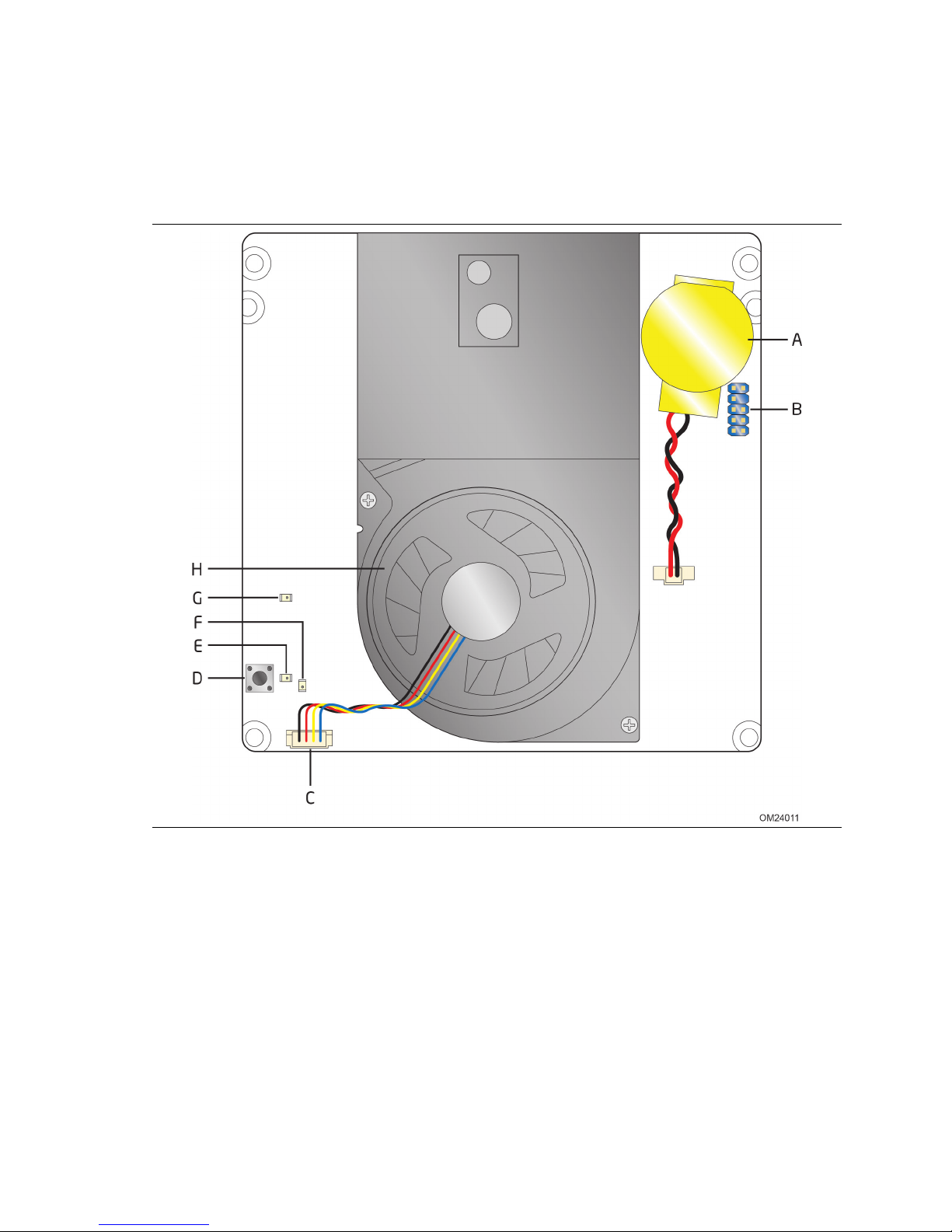
1.1.2 Board Layout (Top)
Figure 1 shows the location of the major components on the top-side of Intel NUC
Board D54250WYB and Intel NUC Board D34010WYB.
Figure 1. Major Board Components (Top)
13
Page 14

Intel NUC Board D54250WYB and Intel NUC Board D34010WYB
Technical Product Specification
Table 2 lists the components identified in Figure 1.
Table 2. Components Shown in Figure 1
Item from Figure 1 Description
A Battery
B Custom Solutions header (2.0 mm pitch)
C Processor fan header
D Onboard power button
E Power LED
F Standby power LED
G Hard Disk Drive LED
H Thermal solution
14
Page 15
Product Description
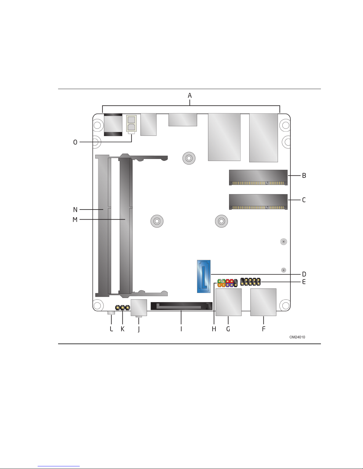
1.1.3 Board Layout (Bottom)
Figure 2 shows the location of the major components on the bottom-side of Intel NUC
Board D54250WYB and Intel NUC Board D34010WYB.
Figure 2. Major Board Components (Bottom)
15
Page 16

Intel NUC Board D54250WYB and Intel NUC Board D34010WYB
Technical Product Specification
Table 3. Components Shown in Figure 2
Item from
Figure 2
A Back panel connectors
B PCI Express Full-Mini Card connector
C PCI Express Half-Mini Card connector
D SATA 6.0 Gb/s connector
E Front panel dual-port USB 2.0 header (2.0 mm pitch)
F Front panel USB 3.0 connector
G Front panel USB 3.0 connector
H Front panel header (2.0 mm pitch)
I SATA power connector
J Front panel stereo microphone/headphone jack
K BIOS setup configuration jumper
L Consumer Infrared (CIR) sensor
M DDR3L SO-DIMM 2 socket
N DDR3L SO-DIMM 1 socket
O Internal DC power connector
Description
16
Page 17
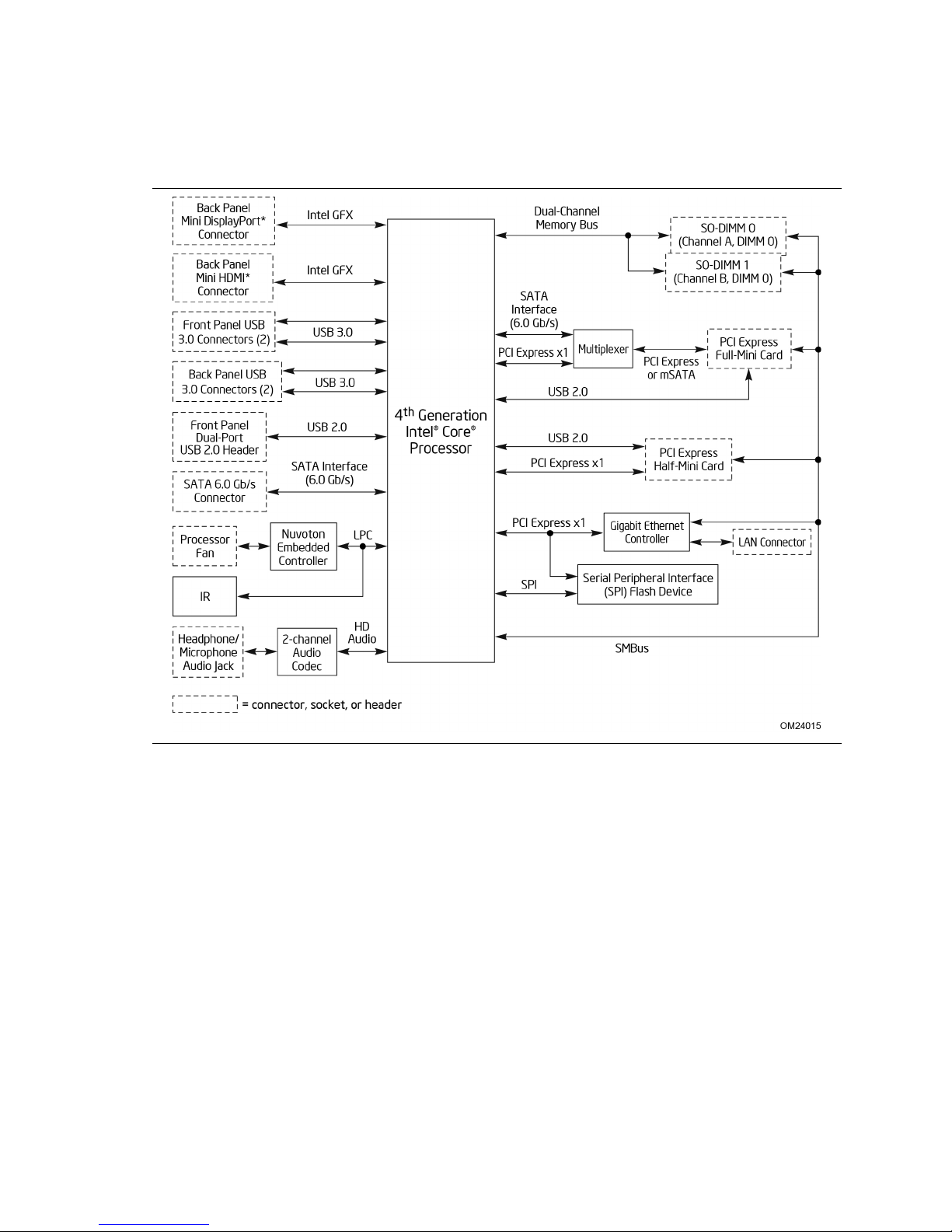
1.1.4 Block Diagram
Figure 3 is a block diagram of the major functional areas of the board.
Product Description
Figure 3. Block Diagram
17
Page 18

Intel NUC Board D54250WYB and Intel NUC Board D34010WYB
To find information about…
Visit this World Wide Web site:
Technical Product Specification
1.2 Online Support
Intel NUC Board D54250WYB and Intel
NUC Board D34010WYB
Intel NUC Board Support http://www.intel.com/NUCSupport
Available configurations for Intel NUC
Board D54250WYB and Intel NUC
Board D34010WYB
BIOS and driver updates http://downloadcenter.intel.com
Tested memory http://www.intel.com/NUCSupport
Integration information http://www.intel.com/NUCSupport
Processor datasheet http://ark.intel.com
http://www.intel.com/NUC
http://ark.intel.com
1.3 Processor
• Intel NUC Board D54250WYB has a soldered-down Intel® Core™ i5-4250U
processor with up to 15 W TDP
Integrated graphics
Integrated memory controller
Integrated PCH
• Intel NUC Board D34010WYB has a soldered-down Intel
processor with up to 15 W TDP
Integrated graphics
Integrated memory controller
Integrated PCH
®
Core™ i3-4010U
NOTE
There are specific requirements for providing power to the processor. Refer to
Section 2.5.1 on page 52 for information on power supply requirements.
18
Page 19

Product Description
Capacity
Configuration
Density
Front-side/Back-side
Devices
4096 MB
DS
2 Gbit
256 M x8/256 M x8
16
4096 MB
SS
4 Gbit
512 M x8/empty
8
8192 MB
DS
4 Gbit
512 M x8/512 M x8
16
For information about…
Refer to:
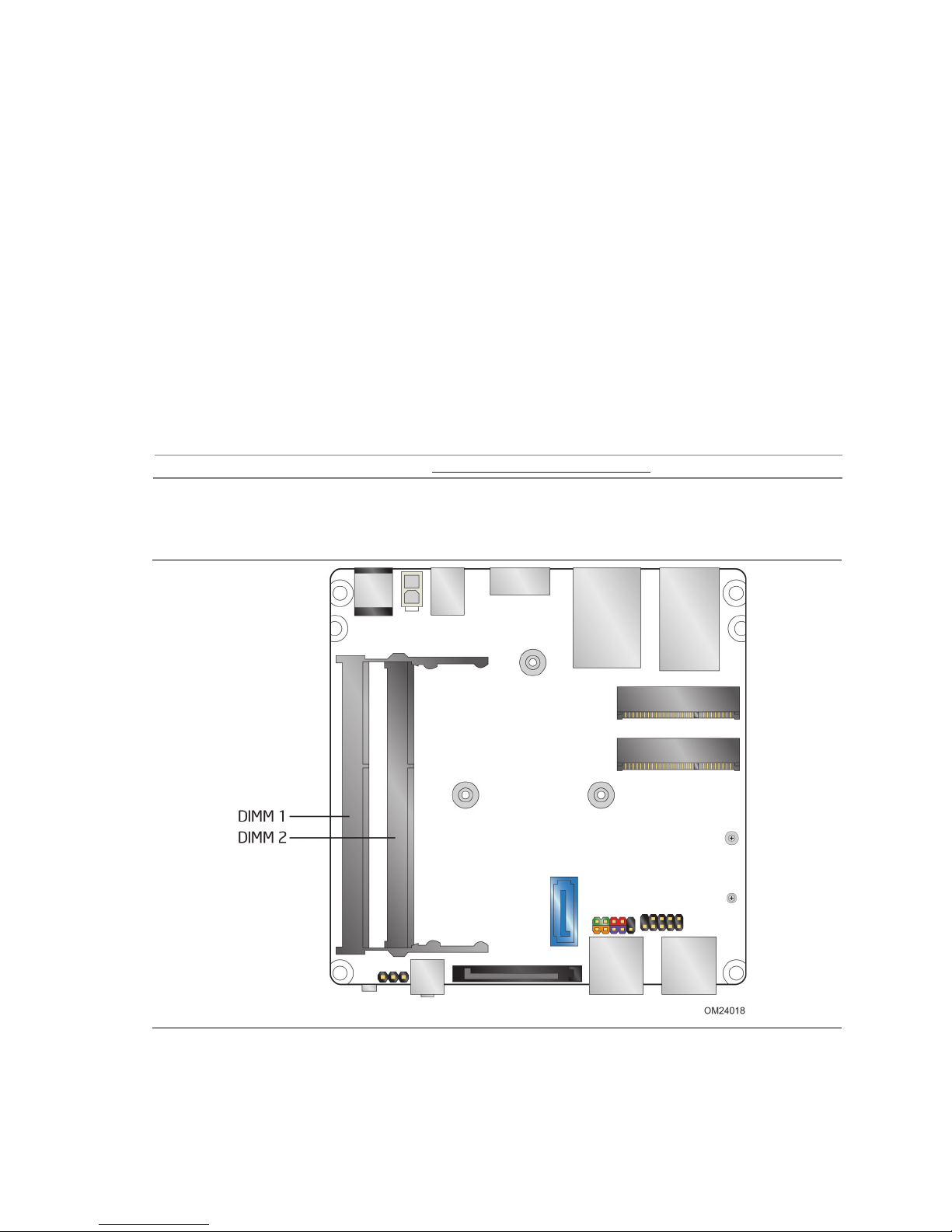
1.4 System Memory
The board has two 204-pin SO-DIMM sockets and support the following memory
features:
• 1.35 V DDR3L SDRAM SO-DIMMs with gold plated contacts
• Two independent memory channels with interleaved mode support
• Unbuffered, single-sided or double-sided SO-DIMMs
• 16 GB maximum total system memory (with 4 Gb memory technology). Refer to
Section 2.1.1 on page 37 for information on the total amount of addressable
memory.
• Minimum recommended total system memory: 1024 MB
• Non-ECC SO-DIMMs
• Serial Presence Detect
• DDR3L 1600 MHz and DDR3L 1333 MHz SDRAM SO-DIMMs
NOTE
To be fully compliant with all applicable DDR SDRAM memory specifications, the board
should be populated with SO-DIMMs that support the Serial Presence Detect (SPD)
data structure. This allows the BIOS to read the SPD data and program the chipset to
accurately configure memory settings for optimum performance. If non-SPD memory
is installed, the BIOS will attempt to correctly configure the memory settings, but
performance and reliability may be impacted or the SO-DIMMs may not function under
the determined frequency.
Table 4 lists the supported SO-DIMM configurations.
Table 4. Supported Memory Configurations
DIMM
Note: “DS” refers to double-sided memory modules (containing two rows of SDRAM) and “SS” refers to
single-sided memory modules (containing one row of SDRAM).
Tested Memory http://www.intel.com/NUCSupport
(Note)
SDRAM
SDRAM Organization
Number of SDRAM
19
Page 20
Intel NUC Board D54250WYB and Intel NUC Board D34010WYB
For information about…
Refer to:
Technical Product Specification
1.4.1 Memory Configurations
The processor supports the following types of memory organization:
• Dual channel (Interleaved) mode. This mode offers the highest throughput for
real world applications. Dual channel mode is enabled when the installed memory
capacities of both SO-DIMM channels are equal. Technology and device width can
vary from one channel to the other but the installed memory capacity for each
channel must be equal. If different speed SO-DIMMs are used between channels,
the slowest memory timing will be used.
• Single channel (Asymmetric) mode. This mode is equivalent to single channel
bandwidth operation for real world applications. This mode is used when only a
single SO-DIMM is installed or the memory capacities are unequal. Technology and
device width can vary from one channel to the other. If different speed SO-DIMMs
are used between channels, the slowest memory timing will be used.
Memory Configuration Examples http://www.intel.com/NUCSupport
Figure 4 illustrates the memory channel and SO-DIMM configuration.
Figure 4. Memory Channel and SO-DIMM Configuration
20
Page 21

Product Description
1.5 Processor Graphics Subsystem
The board supports graphics through Intel HD Graphics.
1.5.1 Integrated Graphics
The board supports integrated graphics via the processor.
1.5.1.1 Intel® High Definition (Intel® HD) Graphics
The Intel HD graphics controller features the following:
• 3D Features
DirectX* 11 support
OpenGL* 4.0 support
• Video
• Next Generation Intel
playback and enhancement features that improve the end user’s viewing
experience
• Encode/transcode HD content
• Playback of high definition content including Blu-ray* disc
• Superior image quality with sharper, more colorful images
• Playback of Blu-ray disc S3D content using Mini HDMI (v1.4a spec compliant
with 3D)
• DirectX* Video Acceleration (DXVA) support for accelerating video processing
• Full AVC/VC1/MPEG2 HW Decode
• Intel
HD Graphics with Advanced Hardware Video Transcoding (Intel
Video)
®
Clear Video Technology HD support is a collection of video
®
Quick Sync
NOTE
Intel Quick Sync Video is enabled by an appropriate software application.
1.5.1.2 Video Memory Allocation
Intel® Dynamic Video Memory Technology (DVMT) is a method for dynamically
allocating system memory for use as graphics memory to balance 2D/3D graphics and
system performance. If your computer is configured to use DVMT, graphics memory is
allocated based on system requirements and application demands (up to the
configured maximum amount). When memory is no longer needed by an application,
the dynamically allocated portion of memory is returned to the operating system for
other uses.
21
Page 22

Intel NUC Board D54250WYB and Intel NUC Board D34010WYB
For information about
Refer to
Technical Product Specification
1.5.1.3 Mini High Definition Multimedia Interface* (Mini HDMI*)
The Mini High-Definition Multimedia Interface (Mini HDMI) is provided for transmitting
uncompressed digital audio and video signals to television sets, projectors and other
video displays. It can carry high quality multi-channel audio data and all standard and
high-definition consumer electronics video formats. The Mini HDMI display interface
connecting the processor and display devices utilizes transition minimized differential
signaling (TMDS) to carry audiovisual information through the same Mini HDMI cable.
The processor HDMI interface is designed according to the High-Definition Multimedia
Interface Specification with 3D, 4K, Deep Color, and x.v.Color. . The maximum
supported resolution is 4096 x 2304, 3840 x 2160 @ 24 Hz or 2560 x1600 @ 60 Hz.
The Mini HDMI port is compliant with the HDMI 1.4a specification.
1.5.1.4 Mini DisplayPort*
DisplayPort is a digital communication interface that utilizes differential signaling to
achieve a high bandwidth bus interface designed to support connections between PCs
and monitors, projectors, and TV displays. DisplayPort is suitable for display
connections between consumer electronics devices such as high definition optical disc
players, set top boxes, and TV displays. The Mini DisplayPort interface supports the
1.2 specification.
The DisplayPort output supports Multi-Stream Transport (MST) which allows for
multiple independent video streams (daisy-chain connection with multiple monitors)
over a single DisplayPort. This will require the use of displays that support
DisplayPort 1.2 and allow for this feature.
DisplayPort technology http://www.displayport.org
22
Page 23

Product Description
Single Display
Dual Display
Single Display
1.5.1.4.1 DisplayPort 1.2 Multi-Stream Transport Daisy-Chaining
Table 5 lists the maximum resolutions available when using DisplayPort 1.2
Multi-Stream Transport.
Table 5. DisplayPort Multi-Streaming Resolutions
DisplayPort Usage
Models
3 Monitors 1920 x 1200 @ 60 Hz 1920 x 1080 @ 60 Hz 1920 x 1080 @ 60 Hz
2 Monitors 2560 x 1600 @ 60 Hz 2560 x 1600 @ 60 Hz
3 Monitors
(with DisplayPort 1.2
hub)
1920 x 1080 @ 60 Hz 1920 x 1080 @ 60 Hz 1920 x 1080 @ 60 Hz
Monitor 1
Monitor 2
Monitor 3
1.5.1.5 Multiple DisplayPort and HDMI Configurations
Multiple DisplayPort and HDMI configurations feature the following:
• Two independent displays
• Single HDMI 1.4a with 4K support
• Single DisplayPort 1.2 with 4K support
• Collage Display
Table 6. Multiple Display Configuration Maximum Resolutions
HDMI
3840 x 2160 @ 30 Hz 3840 x 2160 @ 60 Hz (DisplayPort)
Note: Higher resolutions may be achievable but have not been tested on Intel NUC.
For information about Refer to
Multiple display maximum
resolutions
DisplayPort and HDMI
3840 x 2160 @ 30 Hz (HDMI)
https://wwwssl.intel.com/content/www/us/en/processors/core/CoreTechnicalResou
rces.html (Generic link)
https://www-ssl.intel.com/content/www/us/en/processors/core/4thgen-core-family-desktop-vol-1-datasheet (Specific Link)
DisplayPort
3840 x 2160 @ 60 Hz
1.5.1.6 High-bandwidth Digital Content Protection (HDCP)
HDCP is the technology for protecting high definition content against unauthorized
copy or interception between a source (computer, digital set top boxes, etc.) and the
sink (panels, monitor, and TVs). The PCH supports HDCP 1.4a for content protection
over wired displays (Mini HDMI and Mini DisplayPort).
23
Page 24

Intel NUC Board D54250WYB and Intel NUC Board D34010WYB
Audio Formats
Mini HDMI
Mini DisplayPort
Technical Product Specification
1.5.1.7 Integrated Audio Provided by the Mini HDMI and
Mini DisplayPort Interfaces
The Mini HDMI and Mini DisplayPort interfaces from the PCH support audio. The
processor supports two High Definition audio streams on two digital ports
simultaneously.
Table 7 shows the specific audio technologies supported by the PCH.
Table 7. Audio Formats Supported by the Mini HDMI and
Mini DisplayPort Interfaces
AC-3 – Dolby* Digital Yes Yes
Dolby Digital Plus Yes Yes
DTS-HD* Yes Yes
LPCM , 192 kHz/24 bit, 8 channel Yes Yes
Dolby True HD, DTS-HD Master Audio* (Lossless Blu-ray Disc
Audio Format)
Yes Yes
1.5.2 USB
The board supports eight USB ports. All eight ports are high-speed, full-speed, and
low-speed capable. The port arrangement is as follows:
• USB 3.0 ports:
Two front panel USB 3.0 ports are implemented through an external connector
(blue)
Two ports are implemented with vertical back panel connectors (blue)
• USB 2.0 ports:
Two ports via one dual-port internal 2.0 mm pitch header (black)
One port is reserved for the PCI Express Half-Mini Card
One port is reserved for the PCI Express Full-Mini Card
NOTE
Computer systems that have an unshielded cable attached to a USB port may not meet
FCC Class B requirements, even if no device is attached to the cable. Use a shielded
cable that meets the requirements for full-speed devices.
For information about Refer to
The location of the USB connectors on the back panel Figure 9, page 38
The location of the front panel USB headers Figure 2, page 15
24
Page 25

Product Description
1.6 SATA Interface
The board provides the following SATA interfaces:
• One internal mSATA port (PCI Express Full-Mini Card) for SSD support
• One SATA 6.0 Gb/s port (blue)
The PCH provides independent SATA ports with a theoretical maximum transfer rate of
6 Gb/s. A point-to-point interface is used for host to device connections.
1.6.1 AHCI Mode
The board supports AHCI storage mode.
NOTE
In order to use AHCI mode, AHCI must be enabled in the BIOS. Microsoft* Windows* 7
and Windows 8 includes the necessary AHCI drivers without the need to install
separate AHCI drivers during the operating system installation process, however, it is
always good practice to update the AHCI drivers to the latest available by Intel.
1.6.2 Intel® Rapid Storage Technology / SATA RAID
The PCH supports Intel® Rapid Storage Technology, providing both AHCI and
integrated RAID functionality. The RAID capability provides high-performance RAID 0
and 1 functionality on all SATA ports. Other RAID features include hot spare support,
SMART alerting, and RAID 0 auto replace. Software components include an Option
ROM for pre-boot configuration and boot functionality, a Microsoft Windows compatible
driver, and a user interface for configuration and management of the RAID capability
of the PCH.
1.6.3 Intel® Smart Response Technology
Intel® Smart Response Technology is a disk caching solution that can provide improved
computer system performance with improved power savings. It allows configuration of a
computer system with the advantage of having HDDs for maximum storage capacity
with system performance at or near SSD performance levels.
For more information on Intel Smart Response Technology, go to
http://www.intel.com/support/chipsets/sb/CS-032826.htm
NOTE
In order to use supported RAID and Intel Smart Response Technology features, you
must first enable RAID in the BIOS.
25
Page 26

Intel NUC Board D54250WYB and Intel NUC Board D34010WYB
Pin Number
Pin Name
Description
1
Tip
Left Audio Out
2
Ring
Right Audio Out
3
Ring
Common/Ground
4
Sleeve
Audio In
Technical Product Specification
1.7 Real-Time Clock Subsystem
A coin-cell battery (CR2032) powers the real-time clock and CMOS memory. When the
computer is not plugged into a wall socket, the battery has an estimated life of three
years. When the computer is plugged in, the standby current from the power supply
extends the life of the battery. The clock is accurate to ± 13 minutes/year at 25 ºC
with 3.3 VSB applied via the power supply 5 V STBY rail.
NOTE
If the battery and AC power fail, date and time values will be reset and the user will be
notified during the POST.
When the voltage drops below a certain level, the BIOS Setup program settings stored
in CMOS RAM (for example, the date and time) might not be accurate. Replace the
battery with an equivalent one. Figure 1 on page 13 shows the location of the battery.
1.8 Audio Subsystem
The audio subsystem supports the following features:
• Analog line-out/Analog Headphone/Analog Microphone (front panel jack)
• DMIC interface (custom solutions header), with support for mono and stereo digital
microphones
• Support for 44.1 kHz/48 kHz/96 kHz/192 kHz sample rates on all analog outputs
• Support for 44.1 kHz/48 kHz/96 kHz sample rates on all analog inputs
• Front Panel Audio Jack Support (see Figure 5 for 3.5 mm audio jack pin out):
Speakers only
Headphones only
Microphone only
Combo Headphone/Microphone
Figure 5. 4-Pin 3.5 mm (1/8 inch) Audio Jack Pin Out
NOTE
The analog circuit of the front panel audio connector is designed to power headphones
or amplified speakers only. Poor audio quality occurs if passive (nonamplified) speakers
are connected to this output.
26
Page 27

1.8.1 Audio Subsystem Software
Audio software and drivers are available from Intel’s World Wide Web site.
For information about Refer to
Obtaining Audio software and drivers http://downloadcenter.intel.com
1.9 LAN Subsystem
The LAN subsystem consists of the following:
• Intel I218V Gigabit Ethernet Controller (10/100/1000 Mb/s)
• RJ-45 LAN connector with integrated status LEDs
Additional features of the LAN subsystem include:
• CSMA/CD protocol engine
• LAN connect interface between the Processor and the LAN controller
• Power management capabilities
ACPI technology support
LAN wake capabilities
• LAN subsystem software
Product Description
For information about Refer to
LAN software and drivers http://downloadcenter.intel.com
1.9.1 Intel® I218V Gigabit Ethernet Controller
The Intel I218V Gigabit Ethernet Controller supports the following features:
• Compliant with the 1 Gb/s Ethernet 802.3, 802.3u, 802.3z, 802.3ab specifications
• Multi-speed operation: 10/100/1000 Mb/s
• Full-duplex operation at 10/100/1000 Mb/s; Half-duplex operation at 10/100 Mb/s
• Flow control support compliant with the 802.3X specification as well as the specific
operation of asymmetrical flow control defined by 802.3z
• VLAN support compliant with the 802.3q specification
• MAC address filters: perfect match unicast filters, multicast hash filtering,
broadcast filter, and promiscuous mode
1.9.2 LAN Subsystem Software
LAN software and drivers are available from Intel’s World Wide Web site.
For information about Refer to
Obtaining LAN software and drivers http://downloadcenter.intel.com
27
Page 28

Intel NUC Board D54250WYB and Intel NUC Board D34010WYB
Technical Product Specification
1.9.3 RJ-45 LAN Connector with Integrated LEDs
Two LEDs are built into the RJ-45 LAN connector (shown in Figure 5).
Item Description
A Link LED (Green)
B Data Rate LED (Green/Yellow)
Figure 6. LAN Connector LED Locations
Table 8 describes the LED states when the board is powered up and the LAN
subsystem is operating.
Table 8. LAN Connector LED States
LED LED Color LED State Condition
Off LAN link is not established.
Link Green
Data Rate Green/Yellow
On LAN link is established.
Blinking LAN activity is occurring.
Off 10 Mb/s data rate is selected.
Green 100 Mb/s data rate is selected.
Yellow 1000 Mb/s data rate is selected.
28
Page 29

Product Description
For information about
Refer to
1.10 Hardware Management Subsystem
The hardware management features enable the board to be compatible with the Wired
for Management (WfM) specification. The board has several hardware management
features, including thermal and voltage monitoring.
Wired for Management (WfM) Specification www.intel.com/design/archives/wfm/
1.10.1 Hardware Monitoring
The hardware monitoring and fan control subsystem is based on a Nuvoton NCT5577D
embedded controller, which supports the following:
• Processor and system ambient temperature monitoring
• Chassis fan speed monitoring
• Voltage monitoring of +12 V, +5 V, +3.3 V, Memory Vcc (V_SM), +Vccp, PCH Vcc
• SMBus interface
1.10.2 Fan Monitoring
Fan monitoring can be implemented using third-party software.
29
Page 30

Intel NUC Board D54250WYB and Intel NUC Board D34010WYB
Technical Product Specification
1.10.3 Thermal Solution
Figure 6 shows the location of the thermal solution and processor fan header.
Item Description
A Processor fan header
B Thermal solution
Figure 7. Thermal Solution and Fan Header
30
Page 31

Product Description
state…
pressed for
…the system enters this state
(ACPI G2/G5 – Soft off)
(ACPI G0 – working state)
(ACPI G0 – working state)
(ACPI G1 – sleeping state)
(ACPI G0 – working state)
(ACPI G2/G5 – Soft off)
(ACPI G1 – sleeping state)
(ACPI G0 – working state)
1.11 Power Management
Power management is implemented at several levels, including:
• Software support through Advanced Configuration and Power Interface (ACPI)
• Hardware support:
Power Input
Instantly Available PC technology
LAN wake capabilities
Wake from USB
WAKE# signal wake-up support
Wake from S5
Wake from CIR
+5 V Standby Power Indicator LED
1.11.1 ACPI
ACPI gives the operating system direct control over the power management and Plug
and Play functions of a computer. The use of ACPI with this board requires an
operating system that provides full ACPI support. ACPI features include:
• Plug and Play (including bus and device enumeration)
• Power management control of individual devices, add-in boards (some add-in
boards may require an ACPI-aware driver), video displays, and hard disk drives
• Methods for achieving less than 15-watt system operation in the power-on/standby
sleeping state
• A Soft-off feature that enables the operating system to power-off the computer
• Support for multiple wake-up events (see Table 11 on page 33)
• Support for a front panel power and sleep mode switch
Table 9 lists the system states based on how long the power switch is pressed,
depending on how ACPI is configured with an ACPI-aware operating system.
Table 9. Effects of Pressing the Power Switch
If the system is in this
Off
On
On
Sleep
Sleep
(ACPI G1 – sleeping state)
Note: Depending on power management settings in the operating system.
…and the power switch is
Less than four seconds Power-on
Less than four seconds Soft-off/Standby
More than six seconds Fail safe power-off
Less than four seconds Wake-up
More than six seconds Power-off
(ACPI G2/G5 – Soft off)
Note
31
Page 32

Intel NUC Board D54250WYB and Intel NUC Board D34010WYB
(Note 2)
(Note 2)
Technical Product Specification
1.11.1.1 System States and Power States
Under ACPI, the operating system directs all system and device power state
transitions. The operating system puts devices in and out of low-power states based
on user preferences and knowledge of how devices are being used by applications.
Devices that are not being used can be turned off. The operating system uses
information from applications and user settings to put the system as a whole into a
low-power state.
Table 10 lists the power states supported by the board along with the associated
system power targets. See the ACPI specification for a complete description of the
various system and power states.
Table 10. Power States and Targeted System Power
Global States Sleeping States
G0 – working
state
G1 – sleeping
state
G1 – sleeping
state
G2/S5 S5 – Soft off.
G3 –
mechanical off
AC power is
disconnected
from the
computer.
Notes:
1. Total system power is dependent on the system configuration, including add-in boards and peripherals
powered by the system chassis’ power supply.
2. Dependent on the standby power consumption of wake-up devices used in the system.
S0 – working C0 – working D0 – working
S3 – Suspend to
RAM. Context
saved to RAM.
S4 – Suspend to
disk. Context
saved to disk.
Context not saved.
Cold boot is
required.
No power to the
system.
Processor
States
No power D3 – no power
No power D3 – no power
No power D3 – no power
No power D3 – no power for
Device States
state.
except for
wake-up logic.
except for
wake-up logic.
except for
wake-up logic.
wake-up logic,
except when
provided by
battery or
external source.
Targeted System
Power
Full power > 30 W
Power < 5 W
Power < 5 W
Power < 5 W
No power to the system.
Service can be performed
safely.
(Note 1)
(Note 2)
32
Page 33

Product Description
Note 1)
(Note 1)
(Note 1)
(Note 2)
(Note 1)
1.11.1.2 Wake-up Devices and Events
Table 11 lists the devices or specific events that can wake the computer from specific
states.
Table 11. Wake-up Devices and Events
Devices/events that wake up the system… …from this sleep state
(
(Note 3)
Power switch S3, S4, S5
RTC alarm S3, S4, S5
LAN S3, S4, S5
USB S3
WAKE# S3, S4, S5
Consumer IR S3, S4, S5
Notes:
1. S4 implies operating system support only.
2. USB ports must be turned off during S4/S5 states.
3. When Deep S4/S5 is enabled only Wake from RTC and Power Switch is supported.
NOTE
The use of these wake-up events from an ACPI state requires an operating system that
provides full ACPI support. In addition, software, drivers, and peripherals must fully
support ACPI wake events.
1.11.2 Hardware Support
The board provides several power management hardware features, including:
• Wake from Power Button signal
• Instantly Available PC technology
• LAN wake capabilities
• Wake from USB
• WAKE# signal wake-up support
• Wake from S5
• Wake from CIR
• +5 V Standby Power Indicator LED
NOTE
The use of Wake from USB from an ACPI state requires an operating system that
provides full ACPI support.
33
Page 34

Intel NUC Board D54250WYB and Intel NUC Board D34010WYB
Technical Product Specification
1.11.2.1 Power Input
When resuming from an AC power failure, the computer returns to the power state it
was in before power was interrupted (on or off). The computer’s response can be set
using the Last Power State feature in the BIOS Setup program’s Boot menu.
For information about Refer to
The location of the internal power connector Figure 2, page 15
The signal names of the internal power connector Table 13, page 45
1.11.2.2 Instantly Available PC Technology
Instantly Available PC technology enables the board to enter the ACPI S3 (Suspend-toRAM) sleep-state. While in the S3 sleep-state, the computer will appear to be off (the
power supply is off, and the front panel LED is amber if dual colored, or off if single
colored.) When signaled by a wake-up device or event, the system quickly returns to
its last known wake state. Table 11 on page 33 lists the devices and events that can
wake the computer from the S3 state.
The use of Instantly Available PC technology requires operating system support and
drivers for any installed PCI Express add-in card.
1.11.2.3 LAN Wake Capabilities
LAN wake capabilities enable remote wake-up of the computer through a network. The
LAN subsystem monitors network traffic at the Media Independent Interface. Upon
detecting a Magic Packet* frame, the LAN subsystem asserts a wake-up signal that
powers up the computer.
1.11.2.4 Wake from USB
USB bus activity wakes the computer from an ACPI S3 state.
NOTE
Wake from USB requires the use of a USB peripheral that supports Wake from USB.
1.11.2.5 WAKE# Signal Wake-up Support
When the WAKE# signal on the PCI Express bus is asserted, the computer wakes from
an ACPI S3, S4, or S5 state.
1.11.2.6 Wake from S5
When the RTC Date and Time is set in the BIOS, the computer will automatically wake
from an ACPI S5 state.
34
Page 35

Product Description
1.11.2.7 Wake from Consumer IR
CIR activity wakes the computer from an ACPI S3, S4, or S5 state.
1.11.2.8 +5 V Standby Power Indicator LED
The standby power indicator LED shows that power is still present even when the
computer appears to be off. Figure 7 shows the location of the standby power LED.
CAUTION
If AC power has been switched off and the standby power indicator is still lit,
disconnect the power cord before installing or removing any devices connected to the
board. Failure to do so could damage the board and any attached devices.
Figure 8. Location of the Standby Power LED
35
Page 36

Intel NUC Board D54250WYB and Intel NUC Board D34010WYB
Technical Product Specification
36
Page 37

2 Technical Reference
2.1 Memory Resources
2.1.1 Addressable Memory
The board utilizes 32 GB of addressable system memory. Typically the address space
that is allocated for PCI Conventional bus add-in cards, PCI Express configuration
space, BIOS (SPI Flash device), and chipset overhead resides above the top of DRAM
(total system memory). On a system that has 32 GB of system memory installed, it is
not possible to use all of the installed memory due to system address space being
allocated for other system critical functions. These functions include the following:
• BIOS/SPI Flash device (96 Mb)
• Local APIC (19 MB)
• Direct Media Interface (40 MB)
• PCI Express configuration space (256 MB)
• PCH base address registers PCI Express ports (up to 256 MB)
• Memory-mapped I/O that is dynamically allocated for PCI Express add-in cards
(256 MB)
The board provides the capability to reclaim the physical memory overlapped by the
memory mapped I/O logical address space. The board remaps physical memory from
the top of usable DRAM boundary to the 4 GB boundary to an equivalent sized logical
address range located just above the 4 GB boundary. All installed system memory can
be used when there is no overlap of system addresses.
2.2 Connectors and Headers
CAUTION
Only the following connectors and headers have overcurrent protection: back panel
and front panel USB.
The other internal connectors and headers are not overcurrent protected and should
connect only to devices inside the computer’s chassis, such as fans and internal
peripherals. Do not use these connectors or headers to power devices external to the
computer’s chassis. A fault in the load presented by the external devices could cause
damage to the computer, the power cable, and the external devices themselves.
Furthermore, improper connection of USB header single wire connectors may
eventually overload the overcurrent protection and cause damage to the board.
37
Page 38

Intel NUC Board D54250WYB and Intel NUC Board D34010WYB
A
Front panel stereo microphone/
headphone jack
B
USB 3.0 port
C
USB 3.0 port
Item
Description
A
USB 3.0 ports
B
LAN
C
Mini HDMI connector
D
Mini DisplayPort connector
E
12-19 V DC input jack
Technical Product Specification
This section describes the board’s connectors and headers. The connectors and
headers can be divided into these groups:
• Front panel I/O connectors
• Back panel I/O connectors
• On-board I/O connectors and headers (see pages 39 and 40)
2.2.1 Front Panel Connectors
Figure 8 shows the location of the front panel connectors for the board.
Item Description
Figure 9. Front Panel Connectors
2.2.2 Back Panel Connectors
Figure 9 shows the location of the back panel connectors for the board.
Figure 10. Back Panel Connectors
38
Page 39

2.2.3 Header (Top)
Figure 10 shows the location of the header on the top-side of the board.
Technical Reference
Figure 11. Header (Top)
Table 12 lists the header identified in Figure 10.
Table 12. Header Shown in Figure 10
Item from Figure 11
A Custom Solutions header (2.0 mm pitch)
Description
39
Page 40

Intel NUC Board D54250WYB and Intel NUC Board D34010WYB
Technical Product Specification
2.2.4 Connectors and Headers (Bottom)
Figure 10 shows the locations of the connectors and headers on the bottom-side of the
board.
Figure 12. Connectors and Headers (Bottom)
40
Page 41

Table 13 lists the connectors and headers identified in Figure 10.
Table 13. Connectors and Headers Shown in Figure 10
Technical Reference
Item from
Figure 10
A PCI Express Full-Mini Card connector
B PCI Express Half-Mini Card connector
C SATA 6.0 Gb/s connector through the PCH
D Front panel dual-port USB 2.0 header (2.0 mm pitch)
E Front panel header (2.0 mm pitch)
F SATA power connector
G BIOS setup configuration jumper
H Internal DC power connector
Description
41
Page 42

Intel NUC Board D54250WYB and Intel NUC Board D34010WYB
Technical Product Specification
2.2.4.1 Signal Tables for the Connectors and Headers
Table 14. PCI Express Full-/Half-Mini Card Connector
Pin Signal Name Additional Signal Name
1 WAKE#
2 3.3 V
3 Reserved
4 GND
5 Reserved
6 1.5 V
7 CLKREQ#
8 Reserved
9 GND
10 Reserved
11 REFCLK-
12 Reserved
13 REFCLK+
14 Reserved
15 GND
16 Reserved
17 Reserved
18 GND
19 Reserved
20 Reserved
21 GND
22 PERST#
23 PERn0
24 +3.3 V aux
25 PERp0
26 GND
27 GND
28 +1.5 V
29 GND
30 SMB_CLK
31 PETn0
32 SMB_DATA
33 PETp0
34 GND
35 GND
36 USB_D-
37 GND (mSATA) Vendor
38 USB_D+
continued
42
Page 43

Technical Reference
Pin
Signal Name
Additional Signal Name
Pin
Signal Name
Table 14. PCI Express Full-/Half-Mini Card Connector (continued)
39 +3.3 Vaux (mSATA) Vendor
40 GND
41 +3.3 Vaux (mSATA) Vendor
42 LED_WWAN#
43 Reserved
44 LED_WLAN#
45 Reserved (mSATA) Vendor
46 LED_WPAN#
47 Reserved (mSATA) Vendor
48 +1.5V
49 Reserved (mSATA) DA/DSS
50 GND
51 Reserved (mSATA) Presence Detection
52 +3.3V
NOTE
The mSATA signals are routed only to the PCI Express Full-Mini Card connector and
not to the Half-Mini Card connector. These signals are required to support mSATA
modules.
Table 15. Dual-Port Front Panel USB 2.0 Header
Pin Signal Name Pin Signal Name
1 +5 V DC 2 +5 V DC
3 D− 4 D−
5 D+ 6 D+
7 Ground 8 Ground
9 KEY (no pin) 10 No Connect
Table 16. SATA Connector
1 Ground
2 TXP
3 TXN
4 Ground
5 RXN
6 RXP
7 Ground
43
Page 44

Intel NUC Board D54250WYB and Intel NUC Board D34010WYB
Technical Product Specification
Table 17. SATA Power Connector
Pin Signal Name
1 3.3 V DC
2 3.3 V DC
3 3.3 V DC
4 Ground
5 Ground
6 Ground
7 5 V DC
8 5 V DC
9 5 V DC
10 Ground
11 Ground
12 Ground
13 N/A
14 N/A
15 N/A
Table 18. System ID / Custom Solutions Header (2.0 mm Pitch)
Pin Signal Name Pin Signal Name
1 Prog_LED 2 GND
3 HDMI_CEC 4 DMIC_CLK
5 3.3 Vsby 6 DMIC_DATA
7 Key (no pin) 8 SCI/SMI GPIO
9 5 Vsby (2A) 10 WDTO#/GPIO
2.2.4.2 Add-in Card Connectors
The board has the following add-in card connectors:
• One PCI Express Half-Mini Card
• One PCI Express Full-Mini Card
44
Page 45

Technical Reference
For information about
Refer to
Pin
Signal Name
Description
Pin
Signal Name
Description
2.2.4.3 Power Supply Connectors
The board has the following power supply connectors:
• External Power Supply – the board can be powered through a 12-19 V DC
connector on the back panel. The back panel DC connector is compatible with a
5.5 mm/OD (outer diameter) and 2.5 mm/ID (inner diameter) plug, where the
inner contact is +19 (±10%) V DC and the shell is GND. The maximum current
rating is 10 A.
NOTE
External power voltage, 12-19 V DC, is dependent on the type of
power brick used.
• Internal Power Supply – the board can alternatively be powered via the
internal 12-24 V DC 1 x 2 power connector, where pin 1 is GND and pin 2 is
+19 (±10%) V DC.
Table 19. 12-24 V Internal Power Supply Connector
Pin Signal Name
1 Ground
2 +19 V (±10%)
Power supply considerations Section 2.5.1, page 52
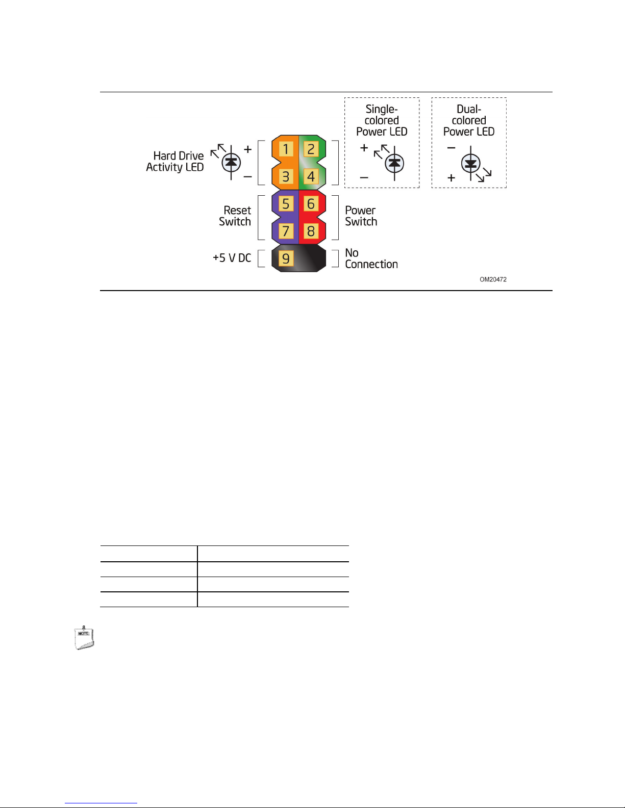
2.2.4.4 Front Panel Header (2.0 mm Pitch)
This section describes the functions of the front panel header. Table 20 lists the signal
names of the front panel header. Figure 11 is a connection diagram for the front panel
header.
Table 20. Front Panel Header (2.0 mm Pitch)
1 HDD_POWER_LED Pull-up resistor
(750 Ω) to +5V
3 HDD_LED# [Out] Hard disk
activity LED
5 GROUND Ground 6 POWER_SWITCH# [In] Power switch
7 RESET_SWITCH# [In] Reset switch 8 GROUND Ground
9 +5V_DC Power 10 Key No pin
2 POWER_LED_MAIN [Out] Front panel LED
(main color)
4 POWER_LED_ALT [Out] Front panel LED
(alt color)
45
Page 46
Intel NUC Board D54250WYB and Intel NUC Board D34010WYB
Technical Product Specification
Figure 13. Connection Diagram for Front Panel Header (2.0 mm Pitch)
2.2.4.4.1 Hard Drive Activity LED Header
Pins 1 and 3 can be connected to an LED to provide a visual indicator that data is
being read from or written to a hard drive. Proper LED function requires a SATA hard
drive or optical drive connected to an onboard SATA connector.
2.2.4.4.2 Reset Switch Header
Pins 5 and 7 can be connected to a momentary single pole, single throw (SPST) type
switch that is normally open. When the switch is closed, the board resets and runs the
POST.
2.2.4.4.3 Power/Sleep LED Header
Pins 2 and 4 can be connected to a one- or two-color LED. Table 21 shows the
possible LED states.
Table 21. States for a One-Color Power LED
LED State Description
Off Power off
Blinking Standby
Steady Normal operation
NOTE
The LED behavior shown in Table 21 is default – other patterns may be set via BIOS
setup.
46
Page 47

Technical Reference
2.2.4.4.4 Power Switch Header
Pins 6 and 8 can be connected to a front panel momentary-contact power switch. The
switch must pull the SW_ON# pin to ground for at least 50 ms to signal the power
supply to switch on or off. (The time requirement is due to internal debounce circuitry
on the board.) At least two seconds must pass before the power supply will recognize
another on/off signal.
2.2.4.5 System ID / Custom Solutions Header (2.0 mm Pitch)
The System ID / Customs Solution header is provided to aid customers in developing
custom applications.
• Prog_LED#: general purpose signal output that indicates when an event was
triggered by the operating system. Signal is amplified by a transistor. Intel can
provide sample code for customers who may want to write their own applications
leveraging this signal.
• SMB_CLK and SMB_DATA: SMBus interface, reserved for future support of All-InOne chassis detection. General SMBus information can be found on the platform
EDS and at http://smbus.org/specs/
• 3.3 V Standby: can be used to monitor the presence of 3.3 V standby power.
• PWRBT#: power button signal (functions in the same manner as the power button
pin on the front panel header).
• HDMI Consumer Electronics Control (CEC): standard communication signal from
the Mini HDMI connector (http://www.hdmi.org/
this header for third party solutions to monitor/control CEC activity between
multiple HDMI devices.
• 5 V Standby: can be used to monitor the presence of 5 V Standby power or provide
power from the 5 V Standby rail (up to 2A current rating).
• SCI/SMI GPI: input signal for direct connection to a front panel push-button to
trigger a Windows command. Intel will be adding BIOS support and accompanying
Windows utility to enable Direct Application Launch* feature. General information
about Direct Application Launch can be found at:
.
) - the signal is exposed through
http://msdn.microsoft.com/en-us/windows/hardware/gg463078.aspx
47
Page 48

Intel NUC Board D54250WYB and Intel NUC Board D34010WYB
Item
Description
A
CIR Sensor
Technical Product Specification
2.2.4.6 Internal USB 2.0 Dual-Port Header (2.0 mm Pitch)
Figure 13 is a connection diagram for the internal USB header.
NOTE
• The +5 V DC power on the USB header is fused.
• Use only an internal USB connector that conforms to the USB 2.0 specification for
high-speed USB devices.
Figure 14. Connection Diagram for Internal
USB 2.0 Dual-Port Header (2.0 mm Pitch)
2.2.4.7 Consumer Infrared (CIR) Sensor
The Consumer Infrared (CIR) sensor on the front panel provides features that are
designed to comply with Microsoft Consumer Infrared usage models.
The CIR feature is made up of the receiving sensor. The receiving sensor consists of a
filtered translated infrared input compliant with Microsoft CIR specifications.
Customers are required to provide their own media center compatible remote or smart
phone application for use with the Intel NUC. Figure 14 shows the location of the CIR
sensor.
48
Figure 15. Location of the CIR Sensor
Page 49

Technical Reference
2.3 BIOS Security Jumper
CAUTION
Do not move a jumper with the power on. Always turn off the power and unplug the
power cord from the computer before changing a jumper setting. Otherwise, the board
could be damaged.
Figure 13 shows the location of the BIOS Security Jumper. The 3-pin jumper
determines the BIOS Security program’s mode.
Table 22 describes the jumper settings for the three modes: normal, lockdown, and
configuration.
Figure 16. Location of the BIOS Security Jumper
49
Page 50

Intel NUC Board D54250WYB and Intel NUC Board D34010WYB
Technical Product Specification
Table 22 lists the settings for the jumper.
Table 22. BIOS Security Jumper Settings
Function/Mode Jumper Setting Configuration
Normal 1-2 The BIOS uses current configuration information and passwords
for booting.
Lockdown 2-3 The BIOS uses current configuration information and passwords
for booting, except:
• All POST Hotkeys are suppressed (prompts are not displayed
and keys are not accepted. For example, F2 for Setup, F10
for the Boot Menu).
• Power Button Menu (see Section 3.7.4)
BIOS updates are not available except for automatic Recovery
due to flash corruption.
Configuration
Mode
None BIOS Recovery Update process if a matching *.bio file is found.
Recovery Update can be cancelled by pressing the Esc key.
If the Recovery Update was cancelled or a matching *.bio file
was not found, a Config Menu will be displayed. The Config
Menu consists of the following (followed by the Power Button
Menu selections):
[1] Suppress this menu until the BIOS Security Jumper is
replaced.
[2] Clear BIOS User and Supervisor Passwords.
[3] Reset Intel AMT to default factory settings.
[4] Clear Trusted Platform Module.
For information on the Power Button Menu, see Section 3.7.4.
50
Page 51

Technical Reference
2.4 Mechanical Considerations
2.4.1 Form Factor
The board is designed to fit into a custom chassis. Figure 16 illustrates the mechanical
form factor for the board. Dimensions are given in inches [millimeters]. The outer
dimensions are 4.0 inches by 4.0 inches [101.60 millimeters by 101.60 millimeters].
Figure 17. Board Dimensions
51
Page 52

Intel NUC Board D54250WYB and Intel NUC Board D34010WYB
Technical Product Specification
2.5 Electrical Considerations
2.5.1 Power Supply Considerations
CAUTION
The external 12-19 V DC jack is the primary power input connector of Intel NUC Board
D54250WYB and Intel NUC Board D34010WYB. However, the board also provides an
internal 1 x 2 power connector that can be used in custom-developed systems that
have an internal power supply. The internal 1 x 2 power connector is a Molex 5566-2
header which accepts a Molex 5557-02R connector from the power supply.
There is no isolation circuitry between the external 12-19 V DC jack and the internal
1 x 2 power connector. It is the system integrator’s responsibility to ensure no more
than one power supply unit is or can be attached to the board at any time and to
ensure the external 12-19 V DC jack is covered if the internal 1 x 2 power connector is
to be used. Simultaneous connection of both external and internal power supply units
could result in potential damage to the board, power supplies, or other hardware.
System power requirements will depend on actual system configurations chosen by the
integrator, as well as end user expansion preferences. It is the system integrator’s
responsibility to ensure an appropriate power budget for the system configuration is
properly assessed based on the system-level components chosen.
• The back panel input range is 12-19 V DC
• The internal power connector input range is 12-24 V DC
52
Page 53

Technical Reference
2.5.2 Fan Header Current Capability
Table 23 lists the current capability of the fan headers.
Table 23. Fan Header Current Capability
Fan Header Maximum Available Current
Processor fan .25 A
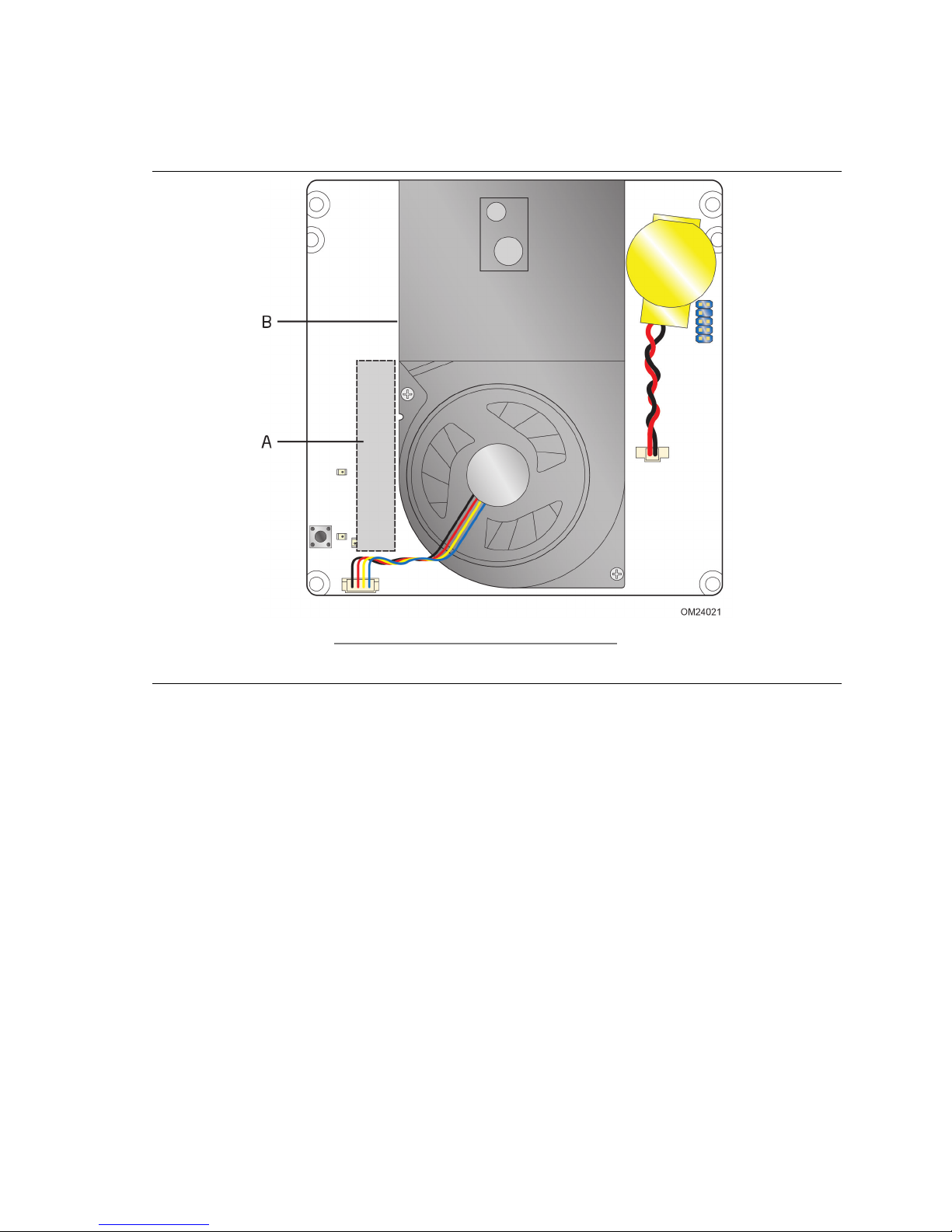
2.6 Thermal Considerations
CAUTION
A chassis with a maximum internal ambient temperature of 50 oC at the processor fan
inlet is a requirement.
CAUTION
Failure to ensure appropriate airflow may result in reduced performance of both the
processor and/or voltage regulator or, in some instances, damage to the board.
All responsibility for determining the adequacy of any thermal or system design
remains solely with the system integrator. Intel makes no warranties or
representations that merely following the instructions presented in this document will
result in a system with adequate thermal performance.
CAUTION
Ensure that the ambient temperature does not exceed the board’s maximum operating
temperature. Failure to do so could cause components to exceed their maximum case
temperature and malfunction. For information about the maximum operating
temperature, see the environmental specifications in Section 2.8.
CAUTION
Ensure that proper airflow is maintained in the processor voltage regulator circuit.
Failure to do so may result in shorter than expected product lifetime.
53
Page 54
Intel NUC Board D54250WYB and Intel NUC Board D34010WYB
Item
Description
A
Processor voltage regulator area
B
Thermal solution
Technical Product Specification
Figure 15 shows the locations of the localized high temperature zones.
Figure 18. Localized High Temperature Zones
54
Page 55

Technical Reference
For information about
Refer to
Table 24 provides maximum case temperatures for the components that are sensitive
to thermal changes. The operating temperature, current load, or operating frequency
could affect case temperatures. Maximum case temperatures are important when
considering proper airflow to cool the board.
Table 24. Thermal Considerations for Components
Component Maximum Case Temperature
Processor For processor case temperature, see processor datasheets and
processor specification updates
To ensure functionality and reliability, the component is specified for proper operation
when Case Temperature is maintained at or below the maximum temperature listed in
Table 25. This is a requirement for sustained power dissipation equal to Thermal
Design Power (TDP is specified as the maximum sustainable power to be dissipated by
the components). When the component is dissipating less than TDP, the case
temperature should be below the Maximum Case Temperature. The surface
temperature at the geometric center of the component corresponds to Case
Temperature.
It is important to note that the temperature measurement in the system BIOS is a
value reported by embedded thermal sensors in the components and does not directly
correspond to the Maximum Case Temperature. The upper operating limit when
monitoring this thermal sensor is Tcontrol.
Table 25. Tcontrol Values for Components
Component Tcontrol
Processor For processor case temperature, see processor datasheets and
processor specification updates
Processor datasheets and specification updates Section 1.2, page 18
55
Page 56

Intel NUC Board D54250WYB and Intel NUC Board D34010WYB
Vibration
Technical Product Specification
2.7 Reliability
The Mean Time Between Failures (MTBF) prediction is calculated using component and
subassembly random failure rates. The calculation is based on the Telcordia SR-332
Issue 2, Method I, Case 3, 55 ºC ambient. The MTBF prediction is used to estimate
repair rates and spare parts requirements. The MTBF for Intel NUC Board D54250WYB
and Intel NUC Board D34010WYB is 66,640 hours.
2.8 Environmental
Table 26 lists the environmental specifications for the board.
Table 26. Environmental Specifications
Parameter Specification
Temperature
Non-Operating
Operating
Shock
Unpackaged 50 g trapezoidal waveform
Velocity change of 170 inches/s²
Packaged Half sine 2 millisecond
Product Weight (pounds) Free Fall (inches) Velocity Change (inches/s²)
<20 36 167
21-40 30 152
41-80 24 136
81-100 18 118
Unpackaged 5 Hz to 20 Hz: 0.01 g² Hz sloping up to 0.02 g² Hz
20 Hz to 500 Hz: 0.02 g² Hz (flat)
Packaged 5 Hz to 40 Hz: 0.015 g² Hz (flat)
40 Hz to 500 Hz: 0.015 g² Hz sloping down to 0.00015 g² Hz
Note: Before attempting to operate this board, the overall temperature of the board must be above the
minimum operating temperature specified. It is recommended that the board temperature be at least
room temperature before attempting to power on the board.
-40 °C to +60 °C
0 °C to +50 °C
The operating temperature of the board may be determined by measuring the
air temperature from the junction of the heatsink fins and fan, next to the
attachment screw, in a closed chassis, while the system is in operation.
56
Page 57

3 Overview of BIOS Features
3.1 Introduction
The board uses a Intel Visual BIOS that is stored in the Serial Peripheral Interface
Flash Memory (SPI Flash) and can be updated using a disk-based program. The SPI
Flash contains the Visual BIOS Setup program, POST, the PCI auto-configuration
utility, LAN EEPROM information, and Plug and Play support.
The BIOS displays a message during POST identifying the type of BIOS and a revision
code. The initial production BIOSs are identified as WYLPT10H.86A.
When the BIOS Setup configuration jumper is set to configure mode and the computer
is powered-up, the BIOS compares the CPU version and the microcode version in the
BIOS and reports if the two match.
The Visual BIOS Setup program can be used to view and change the BIOS settings for
the computer. The BIOS Setup program is accessed by pressing the <F2> key after
the Power-On Self-Test (POST) memory test begins and before the operating system
boot begins.
NOTE
The maintenance menu is displayed only when the board is in configure mode.
Section 2.3 on page 49 shows how to put the board in configure mode.
57
Page 58

Intel NUC Board D54250WYB and Intel NUC Board D34010WYB
Technical Product Specification
3.2 BIOS Flash Memory Organization
The Serial Peripheral Interface Flash Memory (SPI Flash) includes a 64 Mb (8192 KB)
flash memory device.
3.3 System Management BIOS (SMBIOS)
SMBIOS is a Desktop Management Interface (DMI) compliant method for managing
computers in a managed network.
The main component of SMBIOS is the Management Information Format (MIF)
database, which contains information about the computing system and its
components. Using SMBIOS, a system administrator can obtain the system types,
capabilities, operational status, and installation dates for system components. The MIF
database defines the data and provides the method for accessing this information. The
BIOS enables applications such as third-party management software to use SMBIOS.
The BIOS stores and reports the following SMBIOS information:
• BIOS data, such as the BIOS revision level
• Fixed-system data, such as peripherals, serial numbers, and asset tags
• Resource data, such as memory size, cache size, and processor speed
• Dynamic data, such as event detection and error logging
Non-Plug and Play operating systems require an additional interface for obtaining the
SMBIOS information. The BIOS supports an SMBIOS table interface for such operating
systems. Using this support, an SMBIOS service-level application running on a
non-Plug and Play operating system can obtain the SMBIOS information. Additional
board information can be found in the BIOS under the Additional Information header
under the Main BIOS page.
3.4 Legacy USB Support
Legacy USB support enables USB devices to be used even when the operating system’s
USB drivers are not yet available. Legacy USB support is used to access the BIOS
Setup program, and to install an operating system that supports USB. By default,
Legacy USB support is set to Enabled.
Legacy USB support operates as follows:
1. When you apply power to the computer, legacy support is disabled.
2. POST begins.
3. Legacy USB support is enabled by the BIOS allowing you to use a USB keyboard to
enter and configure the BIOS Setup program and the maintenance menu.
4. POST completes.
5. The operating system loads. While the operating system is loading, USB keyboards
and mice are recognized and may be used to configure the operating system.
(Keyboards and mice are not recognized during this period if Legacy USB support
was set to Disabled in the BIOS Setup program.)
58
Page 59

Overview of BIOS Features
For information about
Refer to
6. After the operating system loads the USB drivers, all legacy and non-legacy USB
devices are recognized by the operating system, and Legacy USB support from the
BIOS is no longer used.
7. Additional USB legacy feature options can be access by using Intel® Integrator
Toolkit.
To install an operating system that supports USB, verify that Legacy USB support in
the BIOS Setup program is set to Enabled and follow the operating system’s
installation instructions.
3.5 BIOS Updates
The BIOS can be updated using either of the following utilities, which are available on
the Intel World Wide Web site:
• Intel
• Intel
• Intel
Both utilities verify that the updated BIOS matches the target system to prevent
accidentally installing an incompatible BIOS.
®
Express BIOS Update utility, which enables automated updating while in the
Windows environment. Using this utility, the BIOS can be updated from a file on a
hard disk, a USB drive (a flash drive or a USB hard drive), or a CD-ROM, or from
the file location on the Web.
®
Flash Memory Update Utility, which requires booting from DOS. Using this
utility, the BIOS can be updated from a file on a hard disk, a USB drive (a flash
drive or a USB hard drive), or a CD-ROM.
®
F7 switch during POST allows a user to select where the BIOS .bio file is
located and perform the update from that location/device. Similar to performing a
BIOS Recovery without removing the BIOS configuration jumper.
NOTE
Review the instructions distributed with the upgrade utility before attempting a BIOS
update.
BIOS update utilities http://support.intel.com/support/motherboards/desktop/sb
/CS-034499.htm
3.5.1 Language Support
The BIOS Setup program and help messages are supported in US English. Check the
Intel web site for support.
59
Page 60

Intel NUC Board D54250WYB and Intel NUC Board D34010WYB
Media Type
(Note)
Can be used for BIOS recovery?
For information about
Refer to
Technical Product Specification
3.5.2 Custom Splash Screen
During POST, an Intel® splash screen is displayed by default. This splash screen can
be augmented with a custom splash screen. The Intel Integrator’s Toolkit that is
available from Intel can be used to create a custom splash screen.
NOTE
If you add a custom splash screen, it will share space with the Intel branded logo.
For information about
Intel Integrator Toolkit http://developer.intel.com/design/motherbd/software/itk/
Additional Intel® software tools http://developer.intel.com/design/motherbd/software.htm
Refer to
3.6 BIOS Recovery
It is unlikely that anything will interrupt a BIOS update; however, if an interruption
occurs, the BIOS could be damaged. Table 27 lists the drives and media types that
can and cannot be used for BIOS recovery. The BIOS recovery media does not need to
be made bootable.
Table 27. Acceptable Drives/Media Types for BIOS Recovery
Hard disk drive (connected to SATA or USB) Yes
CD/DVD drive (connected to SATA or USB) Yes
USB flash drive Yes
USB diskette drive (with a 1.4 MB diskette) No (BIOS update file is bigger than 1.4 MB size limit)
NOTE
Supported file systems for BIOS recovery:
• NTFS (sparse, compressed, or encrypted files are not supported)
• FAT32
• FAT16
• FAT12
• ISO 9660
BIOS recovery http://www.intel.com/support/motherboards/desktop/sb/cs-034524.htm
60
Page 61

Overview of BIOS Features
3.7 Boot Options
In the BIOS Setup program, the user can choose to boot from a hard drive, optical
drive, removable drive, or the network. The default setting is for the optical drive to
be the first boot device, the hard drive second, removable drive third, and the network
fourth.
3.7.1 Network Boot
The network can be selected as a boot device. This selection allows booting from the
onboard LAN or a network add-in card with a remote boot ROM installed.
Pressing the <F12> key during POST automatically forces booting from the LAN. To
use this key during POST, the User Access Level in the BIOS Setup program's Security
menu must be set to Full.
3.7.2 Booting Without Attached Devices
For use in embedded applications, the BIOS has been designed so that after passing
the POST, the operating system loader is invoked even if the following devices are not
present:
• Video adapter
• Keyboard
• Mouse
3.7.3 Changing the Default Boot Device During POST
Pressing the <F10> key during POST causes a boot device menu to be displayed. This
menu displays the list of available boot devices. Table 28 lists the boot device menu
options.
Table 28. Boot Device Menu Options
Boot Device Menu Function Keys Description
<↑> or <↓>
<Enter> Exits the menu, and boots from the selected device
<Esc> Exits the menu and boots according to the boot priority
Selects a default boot device
defined through BIOS setup
61
Page 62

Intel NUC Board D54250WYB and Intel NUC Board D34010WYB
Technical Product Specification
3.7.4 Power Button Menu
As an alternative to Back-to-BIOS Mode or normal POST Hotkeys, the user can use the
power button to access a menu. The Power Button Menu is accessible via the following
sequence:
1. System is in S4/S5 (Not G3)
2. User pushes the power button and holds it down
3. The system will emit three short beeps from the PC speaker, then stop to signal the
user to release the power button
4. User releases the power button before the 4-second shutdown override
If this boot path is taken, the BIOS will use default settings, ignoring settings in VPD
where possible.
At the point where Setup Entry/Boot would be in the normal boot path, the BIOS will
display the following prompt and wait for a keystroke:
[ESC] Normal Boot
[F2] Intel Visual BIOS
[F3] Disable Fast Boot
[F4] BIOS Recovery
[F7] Update BIOS
[F9] Remote Assistance
[F10] Enter Boot Menu
[F12] Network Boot
[F2] Enter Setup is displayed instead if Visual BIOS is not supported.
[F3] Disable Fast Boot is only displayed if at least one Fast Boot optimization is
enabled.
[F9] Remote Assistance is only displayed if Remote Assistance is supported.
If an unrecognized key is hit, then the BIOS will beep and wait for another keystroke.
If one of the listed hotkeys is hit, the BIOS will follow the indicated boot path.
Password requirements must still be honored.
If Disable Fast Boot is selected, the BIOS will disable all Fast Boot optimizations and
reset the system.
62
Page 63

Overview of BIOS Features
Password Set
Password During Boot
3.8 Hard Disk Drive Password Security Feature
The Hard Disk Drive Password Security feature blocks read and write accesses to the
hard disk drive until the correct password is given. Hard Disk Drive Passwords are set
in BIOS SETUP and are prompted for during BIOS POST. For convenient support of S3
resume, the system BIOS will automatically unlock drives on resume from S3. Valid
password characters are A-Z, a-z, and 0-9. Passwords may be up to 16 characters in
length.
The User hard disk drive password, when installed, will be required upon each powercycle until the Master Key or User hard disk drive password is submitted.
The Master Key hard disk drive password, when installed, will not lock the drive. The
Master Key hard disk drive password exists as an unlock override in the event that the
User hard disk drive password is forgotten. Only the installation of the User hard disk
drive password will cause a hard disk to be locked upon a system power-cycle.
Table 29 shows the effects of setting the Hard Disk Drive Passwords.
Table 29. Master Key and User Hard Drive Password Functions
Neither None
Master only None
User only User only
Master and User Set Master or User
During every POST, if a User hard disk drive password is set, POST execution will
pause with the following prompt to force the user to enter the Master Key or User hard
disk drive password:
Enter Hard Disk Drive Password:
Upon successful entry of the Master Key or User hard disk drive password, the system
will continue with normal POST.
If the hard disk drive password is not correctly entered, the system will go back to the
above prompt. The user will have three attempts to correctly enter the hard disk drive
password. After the third unsuccessful hard disk drive password attempt, the system
will halt with the message:
Hard Disk Drive Password Entry Error
A manual power cycle will be required to resume system operation.
NOTE
As implemented on Intel NUC Board D54250WYB and Intel NUC Board D34010WYB,
Hard Disk Drive Password Security is only supported on either SATA port 0 (mSATA) or
SATA Port 1 (onboard SATA connector). The passwords are stored on the hard disk
drive so if the drive is relocated to another computer that does not support Hard Disk
Drive Password Security feature, the drive will not be accessible.
63
Page 64

Intel NUC Board D54250WYB and Intel NUC Board D34010WYB
Technical Product Specification
3.9 BIOS Security Features
The BIOS includes security features that restrict access to the BIOS Setup program
and who can boot the computer. A supervisor password and a user password can be
set for the BIOS Setup program and for booting the computer, with the following
restrictions:
• The supervisor password gives unrestricted access to view and change all the Setup
options in the BIOS Setup program. This is the supervisor mode.
• The user password gives restricted access to view and change Setup options in the
BIOS Setup program. This is the user mode.
• If only the supervisor password is set, pressing the <Enter> key at the password
prompt of the BIOS Setup program allows the user restricted access to Setup.
• If both the supervisor and user passwords are set, users can enter either the
supervisor password or the user password to access Setup. Users have access to
Setup respective to which password is entered.
• Setting the user password restricts who can boot the computer. The password
prompt will be displayed before the computer is booted. If only the supervisor
password is set, the computer boots without asking for a password. If both
passwords are set, the user can enter either password to boot the computer.
• For enhanced security, use different passwords for the supervisor and user
passwords.
• Valid password characters are A-Z, a-z, and 0-9. Passwords may be up to
16 characters in length.
• To clear a set password, enter a blank password after entering the existing
password.
Table 30 shows the effects of setting the supervisor password and user password. This
table is for reference only and is not displayed on the screen.
Table 30. Supervisor and User Password Functions
Password
Set
Neither Can change all
Supervisor
only
User only N/A Can change all
Supervisor
and user set
Note: If no password is set, any user can change all Setup options.
Supervisor
Mode
options
Can change all
options
Can change all
options
(Note)
User Mode
Can change all
options
Can change a
limited
number of
options
options
Can change a
limited
number of
options
(Note)
Setup Options
None None None
Supervisor Password Supervisor None
Enter Password
Clear User Password
Supervisor Password
Enter Password
Password
to Enter
Setup
User User
Supervisor or
user
Password
During
Boot
Supervisor or
user
64
Page 65

(Note)
4 Error Messages and Blink Codes
4.1 Front-panel Power LED Blink Codes
Whenever a recoverable error occurs during POST, the BIOS causes the board’s front
panel power LED to blink an error message describing the problem (see Table 31).
Table 31. Front-panel Power LED Blink Codes
Type Pattern Note
BIOS update in progress Off when the update begins, then on for
0.5 seconds, then off for 0.5 seconds. The
pattern repeats until the BIOS update is
complete.
Video error
Memory error On-off (1.0 second each) three times, then
Thermal trip warning Each beep will be accompanied by the following
Note: Disabled per default BIOS setup option.
On-off (1.0 second each) two times, then
2.5-second pause (off), entire pattern repeats
(blink and pause) until the system is powered
off.
2.5-second pause (off), entire pattern repeats
(blinks and pause) until the system is powered
off.
blink pattern: .25 seconds on, .25 seconds off,
.25 seconds on, .25 seconds off. This will result
in a total of 16 blinks.
When no VGA option ROM is
found.
4.2 BIOS Error Messages
Table 32 lists the error messages and provides a brief description of each.
Table 32. BIOS Error Messages
Error Message Explanation
CMOS Battery Low The battery may be losing power. Replace the battery soon.
CMOS Checksum Bad The CMOS checksum is incorrect. CMOS memory may have
Memory Size Decreased Memory size has decreased since the last boot. If no memory
No Boot Device Available System did not find a device to boot.
been corrupted. Run Setup to reset values.
was removed, then memory may be bad.
65
Page 66

Intel NUC Board D54250WYB and Intel NUC Board D34010WYB
Technical Product Specification
66
Page 67

5 Regulatory Compliance and Battery
Disposal Information
5.1 Regulatory Compliance
This section contains the following regulatory compliance information for Intel NUC
Board D54250WYB and Intel NUC Board D34010WYB:
• Safety standards
• European Union Declaration of Conformity statement
• Product Ecology statements
• Electromagnetic Compatibility (EMC) standards
• Product certification markings
5.1.1 Safety Standards
Intel NUC Board D54250WYB and Intel NUC Board D34010WYB comply with the safety
standards stated in Table 33 when correctly installed in a compatible host system.
Table 33. Safety Standards
Standard Title
CSA/UL 60950-1 Information Technology Equipment – Safety - Part 1: General
Requirements (USA and Canada)
EN 60950-1 Information Technology Equipment – Safety - Part 1: General
Requirements (European Union)
IEC 60950-1 Information Technology Equipment – Safety - Part 1: General
Requirements (International)
67
Page 68

Intel NUC Board D54250WYB and Intel NUC Board D34010WYB
Technical Product Specification
5.1.2 European Union Declaration of Conformity
Statement
We, Intel Corporation, declare under our sole responsibility that the products Intel®
NUC Board D54250WYB and Intel
®
NUC Board D34010WYB are in conformity with all
applicable essential requirements necessary for CE marking, following the provisions of
the European Council Directive 2004/108/EC (EMC Directive), 2006/95/EC (Low
Voltage Directive), and 2011/65/EU (ROHS Directive).
The product is properly CE marked demonstrating this conformity and is for
distribution within all member states of the EU with no restrictions.
This product follows the provisions of the European Directives 2004/108/EC,
2006/95/EC, and 2011/65/EU.
Čeština Tento výrobek odpovídá požadavkům evropských směrnic 2004/108/EC,
2006/95/EC a 2002/95/EC.
Dansk Dette produkt er i overensstemmelse med det europæiske direktiv
2004/108/EC, 2006/95/EC & 2002/95/EC.
Dutch Dit product is in navolging van de bepalingen van Europees Directief
2004/108/EC, 2006/95/EC & 2002/95/EC.
Eesti Antud toode vastab Euroopa direktiivides 2004/108/EC, ja 2006/95/EC ja
2002/95/EC kehtestatud nõuetele.
Suomi Tämä tuote noudattaa EU-direktiivin 2004/108/EC, 2006/95/EC & 2002/95/EC
määräyksiä.
Français Ce produit est conforme aux exigences de la Directive Européenne
2004/108/EC, 2006/95/EC & 2002/95/EC.
Deutsch Dieses Produkt entspricht den Bestimmungen der Europäischen Richtlinie
2004/108/EC, 2006/95/EC & 2002/95/EC.
Ελληνικά Το παρόν προϊόν ακολουθεί τις διατάξεις των Ευρωπαϊκών Οδηγιών
2004/108/EC, 2006/95/EC και 2002/95/EC.
Magyar E termék megfelel a 2004/108/EC, 2006/95/EC és 2002/95/EC Európai
Irányelv előírásainak.
Icelandic Þessi vara stenst reglugerð Evrópska Efnahags Bandalagsins númer
2004/108/EC, 2006/95/EC, & 2002/95/EC.
Italiano Questo prodotto è conforme alla Direttiva Europea 2004/108/EC,
2006/95/EC & 2002/95/EC.
Latviešu Šis produkts atbilst Eiropas Direktīvu 2004/108/EC, 2006/95/EC un
2002/95/EC noteikumiem.
Lietuvių Šis produktas atitinka Europos direktyvų 2004/108/EC, 2006/95/EC, ir
2002/95/EC nuostatas.
Malti Dan il-prodott hu konformi mal-provvedimenti tad-Direttivi Ewropej
2004/108/EC, 2006/95/EC u 2002/95/EC.
Norsk Dette produktet er i henhold til bestemmelsene i det europeiske direktivet
2004/108/EC, 2006/95/EC & 2002/95/EC.
Polski Niniejszy produkt jest zgodny z postanowieniami Dyrektyw Unii Europejskiej
2004/108/EC, 206/95/EC i 2002/95/EC.
68
Page 69

Regulatory Compliance and Battery Disposal Information
Regulation
Title
Portuguese Este produto cumpre com as normas da Diretiva Européia 2004/108/EC,
2006/95/EC & 2002/95/EC.
Español Este producto cumple con las normas del Directivo Europeo 2004/108/EC,
2006/95/EC & 2002/95/EC.
Slovensky Tento produkt je v súlade s ustanoveniami európskych direktív
2004/108/EC, 2006/95/EC a 2002/95/EC.
Slovenščina Izdelek je skladen z določbami evropskih direktiv 2004/108/EC,
2006/95/EC in 2002/95/EC.
Svenska Denna produkt har tillverkats i enlighet med EG-direktiv 2004/108/EC,
2006/95/EC & 2002/95/EC.
Türkçe Bu ürün, Avrupa Birliği’nin 2004/108/EC, 2006/95/EC ve 2002/95/EC
yönergelerine uyar.
5.1.3 EMC Regulations
Intel NUC Board D54250WYB and Intel NUC Board D34010WYB comply with the EMC
regulations stated in Table 34 when correctly installed in a compatible host system.
Table 34. EMC Regulations
FCC 47 CFR Part 15,
Subpart B
ICES-003 Interference-Causing Equipment Standard, Digital Apparatus. (Canada)
EN55022 Limits and methods of measurement of Radio Interference Characteristics
EN55024 Information Technology Equipment – Immunity Characteristics Limits and
EN55022 Australian Communications Authority, Standard for Electromagnetic
CISPR 22 Limits and methods of measurement of Radio Disturbance Characteristics
CISPR 24 Information Technology Equipment – Immunity Characteristics – Limits
VCCI V-3, V-4 Voluntary Control for Interference by Information Technology Equipment.
KN-22, KN-24 Korean Communications Commission – Framework Act on
CNS 13438 Bureau of Standards, Metrology, and Inspection (Taiwan)
Title 47 of the Code of Federal Regulations, Part 15, Subpart B, Radio
Frequency Devices. (USA)
of Information Technology Equipment. (European Union)
methods of measurement. (European Union)
Compatibility. (Australia and New Zealand)
of Information Technology Equipment. (International)
and Methods of Measurement. (International)
(Japan)
Telecommunications and Radio Waves Act (South Korea)
FCC Declaration of Conformity
This device complies with Part 15 of the FCC Rules. Operation is subject to the
following two conditions: (1) this device may not cause harmful interference, and (2)
this device must accept any interference received, including interference that may
cause undesired operation.
For questions related to the EMC performance of this product, contact:
Intel Corporation, 5200 N.E. Elam Young Parkway, Hillsboro, OR 97124
1-800-628-8686
69
Page 70

Intel NUC Board D54250WYB and Intel NUC Board D34010WYB
Technical Product Specification
This equipment has been tested and found to comply with the limits for a Class B
digital device, pursuant to Part 15 of the FCC Rules. These limits are designed to
provide reasonable protection against harmful interference in a residential installation.
This equipment generates, uses, and can radiate radio frequency energy and, if not
installed and used in accordance with the instructions, may cause harmful interference
to radio communications. However, there is no guarantee that interference will not
occur in a particular installation. If this equipment does cause harmful interference to
radio or television reception, which can be determined by turning the equipment off
and on, the user is encouraged to try to correct the interference by one or more of the
following measures:
• Reorient or relocate the receiving antenna.
• Increase the separation between the equipment and the receiver.
• Connect the equipment to an outlet on a circuit other than the one to which the
receiver is connected.
• Consult the dealer or an experienced radio/TV technician for help.
Any changes or modifications to the equipment not expressly approved by Intel
Corporation could void the user’s authority to operate the equipment.
Tested to comply with FCC standards for home or office use.
Canadian Department of Communications Compliance Statement
This digital apparatus does not exceed the Class B limits for radio noise emissions from
digital apparatus set out in the Radio Interference Regulations of the Canadian
Department of Communications.
Le présent appareil numerique német pas de bruits radioélectriques dépassant les
limites applicables aux appareils numériques de la classe B prescrites dans le
Réglement sur le broullage radioélectrique édicté par le ministére des Communications
du Canada.
70
Page 71

Regulatory Compliance and Battery Disposal Information
Japan VCCI Statement
Japan VCCI Statement translation: This is a Class B product based on the standard of
the Voluntary Control Council for Interference from Information Technology Equipment
(VCCI). If this is used near a radio or television receiver in a domestic environment, it
may cause radio interference. Install and use the equipment according to the
instruction manual.
Korea Class B Statement
Korea Class B Statement translation: This equipment is for home use, and has
acquired electromagnetic conformity registration, so it can be used not only in
residential areas, but also other areas.
71
Page 72

Intel NUC Board D54250WYB and Intel NUC Board D34010WYB
Technical Product Specification
5.1.4 e-Standby and ErP Compliance
Intel NUC Board D54250WYB and Intel NUC Board D34010WYB meet the following
program requirements in an adequate system configuration, including appropriate
selection of an efficient power supply:
• EPEAT*
• Korea e-Standby
• European Union Energy-related Products Directive 2013 (ErP) Lot 6
For information about Refer to
Electronic Product Environmental Assessment Tool (EPEAT) http://www.epeat.net/
Korea e-Standby Program http://www.kemco.or.kr/new_eng/pg02
/pg02100300.asp
European Union Energy-related Products Directive 2009 (ErP) http://ec.europa.eu/enterprise/policies/s
ustainable-business/sustainableproduct-policy/ecodesign/index_en.htm
72
Page 73

Regulatory Compliance and Battery Disposal Information
Description
Mark
5.1.5 Regulatory Compliance Marks (Board Level)
Intel NUC Board D54250WYB and Intel NUC Board D34010WYB have the regulatory
compliance marks shown in Table 35.
Table 35. Regulatory Compliance Marks
UL joint US/Canada Recognized Component mark. Includes adjacent UL file
number for Intel NUC: E210882.
FCC Declaration of Conformity logo mark for Class B equipment.
CE mark. Declaring compliance to the European Union (EU) EMC directive,
Low Voltage directive, and RoHS directive.
For CE Mark-Related Questions:
Intel Corporation
Attn: Corporate Quality
2200 Mission College Blvd.
Santa Clara, CA 95054-1549
USA
Australian Communications Authority (ACA) and New Zealand Radio
Spectrum Management (NZ RSM) C-tick mark. Includes adjacent Intel
supplier code number, N-232.
Japan VCCI (Voluntary Control Council for Interference) mark.
Korea Certification mark. Includes an adjacent MSIP (Ministry of Science,
ICT & Future Planning) certification number:
MSIP-REM-CPU-D54250WYB and MSIP-REM-CPU -D34010WYB.
Taiwan BSMI (Bureau of Standards, Metrology and Inspections) mark.
Includes adjacent Intel company number, D33025.
Printed wiring board manufacturer’s recognition mark. Consists of a unique
UL recognized manufacturer’s logo, along with a flammability rating (solder
side).
China RoHS/Environmentally Friendly Use Period Logo: This is an example of
the symbol used on Intel NUC and associated collateral. The color of the
mark may vary depending upon the application. The Environmental Friendly
Usage Period (EFUP) for Intel NUC has been determined to be 10 years.
V-0
73
Page 74

Intel NUC Board D54250WYB and Intel NUC Board D34010WYB
PRÉCAUTION
FORHOLDSREGEL
OBS!
VIKTIGT!
VARO
VORSICHT
AVVERTIMENTO
Technical Product Specification
5.2 Battery Disposal Information
CAUTION
Risk of explosion if the battery is replaced with an incorrect type. Batteries should be
recycled where possible. Disposal of used batteries must be in accordance with local
environmental regulations.
Risque d'explosion si la pile usagée est remplacée par une pile de type incorrect. Les
piles usagées doivent être recyclées dans la mesure du possible. La mise au rebut des
piles usagées doit respecter les réglementations locales en vigueur en matière de
protection de l'environnement.
Eksplosionsfare, hvis batteriet erstattes med et batteri af en forkert type. Batterier bør
om muligt genbruges. Bortskaffelse af brugte batterier bør foregå i overensstemmelse
med gældende miljølovgivning.
Det kan oppstå eksplosjonsfare hvis batteriet skiftes ut med feil type. Brukte batterier
bør kastes i henhold til gjeldende miljølovgivning.
Risk för explosion om batteriet ersätts med felaktig batterityp. Batterier ska kasseras
enligt de lokala miljövårdsbestämmelserna.
Räjähdysvaara, jos pariston tyyppi on väärä. Paristot on kierrätettävä, jos se on
mahdollista. Käytetyt paristot on hävitettävä paikallisten ympäristömääräysten
mukaisesti.
Bei falschem Einsetzen einer neuen Batterie besteht Explosionsgefahr. Die Batterie
darf nur durch denselben oder einen entsprechenden, vom Hersteller empfohlenen
Batterietyp ersetzt werden. Entsorgen Sie verbrauchte Batterien den Anweisungen des
Herstellers entsprechend.
Esiste il pericolo di un esplosione se la pila non viene sostituita in modo corretto.
Utilizzare solo pile uguali o di tipo equivalente a quelle consigliate dal produttore. Per
disfarsi delle pile usate, seguire le istruzioni del produttore.
74
Page 75

Regulatory Compliance and Battery Disposal Information
PRECAUCIÓN
WAARSCHUWING
ATENÇÃO
AŚCIAROŽZNAŚĆ
UPOZORNÌNÍ
Προσοχή
VIGYÁZAT
Existe peligro de explosión si la pila no se cambia de forma adecuada. Utilice
solamente pilas iguales o del mismo tipo que las recomendadas por el fabricante del
equipo. Para deshacerse de las pilas usadas, siga igualmente las instrucciones del
fabricante.
Er bestaat ontploffingsgevaar als de batterij wordt vervangen door een onjuist type
batterij. Batterijen moeten zoveel mogelijk worden gerecycled. Houd u bij het
weggooien van gebruikte batterijen aan de plaatselijke milieuwetgeving.
Haverá risco de explosão se a bateria for substituída por um tipo de bateria incorreto.
As baterias devem ser recicladas nos locais apropriados. A eliminação de baterias
usadas deve ser feita de acordo com as regulamentações ambientais da região.
Існуе рызыка выбуху, калі заменены акумулятар неправільнага тыпу.
Акумулятары павінны, па магчымасці, перепрацоўвацца. Пазбаўляцца ад старых
акумулятараў патрэбна згодна з мясцовым заканадаўствам па экалогіі.
V případě výměny baterie za nesprávný druh může dojít k výbuchu. Je-li to možné,
baterie by měly být recyklovány. Baterie je třeba zlikvidovat v souladu s místními
předpisy o životním prostředí.
Υπάρχει κίνδυνος για έκρηξη σε περίπτωση που η μπαταρία αντικατασταθεί από μία
λανθασμένου τύπου. Οι μπαταρίες θα πρέπει να ανακυκλώνονται όταν κάτι τέτοιο είναι
δυνατό. Η απόρριψη των χρησιμοποιημένων μπαταριών πρέπει να γίνεται σύμφωνα με
τους κατά τόπο περιβαλλοντικούς κανονισμούς.
Ha a telepet nem a megfelelő típusú telepre cseréli, az felrobbanhat. A telepeket
lehetőség szerint újra kell hasznosítani. A használt telepeket a helyi környezetvédelmi
előírásoknak megfelelően kell kiselejtezni.
75
Page 76
Intel NUC Board D54250WYB and Intel NUC Board D34010WYB
AWAS
OSTRZEŻENIE
PRECAUŢIE
ВНИМАНИЕ
UPOZORNENIE
POZOR
UYARI
OСТОРОГА
Technical Product Specification
Risiko letupan wujud jika bateri digantikan dengan jenis yang tidak betul. Bateri
sepatutnya dikitar semula jika boleh. Pelupusan bateri terpakai mestilah mematuhi
peraturan alam sekitar tempatan.
Istnieje niebezpieczeństwo wybuchu w przypadku zastosowania niewłaściwego typu
baterii. Zużyte baterie należy w miarę możliwości utylizować zgodnie z odpowiednimi
przepisami ochrony środowiska.
Risc de explozie, dacă bateria este înlocuită cu un tip de baterie necorespunzător.
Bateriile trebuie reciclate, dacă este posibil. Depozitarea bateriilor uzate trebuie să
respecte reglementările locale privind protecţia mediului.
При использовании батареи несоответствующего типа существует риск ее взрыва.
Батареи должны быть утилизированы по возможности. Утилизация батарей должна
проводится по правилам, соответствующим местным требованиям.
Ak batériu vymeníte za nesprávny typ, hrozí nebezpečenstvo jej výbuchu.
Batérie by sa mali podľa možnosti vždy recyklovať. Likvidácia použitých batérií sa musí
vykonávať v súlade s miestnymi predpismi na ochranu životného prostredia.
Zamenjava baterije z baterijo drugačnega tipa lahko povzroči eksplozijo.
Če je mogoče, baterije reciklirajte. Rabljene baterije zavrzite v skladu z lokalnimi
okoljevarstvenimi predpisi.
Yanlış türde pil takıldığında patlama riski vardır. Piller mümkün olduğunda geri
dönüştürülmelidir. Kullanılmış piller, yerel çevre yasalarına uygun olarak atılmalıdır.
Використовуйте батареї правильного типу, інакше існуватиме ризик вибуху.
Якщо можливо, використані батареї слід утилізувати. Утилізація використаних
батарей має бути виконана згідно місцевих норм, що регулюють охорону довкілля.
76
Page 77

Regulatory Compliance and Battery Disposal Information
77
Page 78

Intel NUC Board D54250WYB and Intel NUC Board D34010WYB
Technical Product Specification
78
 Loading...