


 Loading...
2013 M35h HYBRID
Dismantling Guide
1

Foreword
This manual describes dismantling operations and important safety related warnings and cautions for this vehicle.
This vehicle is equipped with a high voltage Lithium-ion (Li-on) battery pack. Failure to follow recommended practices during dismantling will cause death or serious personal injury.
Please read this manual in advance in order to understand the features of this vehicle and to help you deal with dismantling operations involving this vehicle. Follow the procedures in order to help assure a successful dismantling operation.
INFINITI EMERGENCY CONTACT INFORMATION
•1-800-662-6200 (US) or 1-800-361-4792 (Canada)
•Hours of operation are 8am-5pm (Monday-Friday) Eastern, Central and Pacific time zones
IMPORTANT INFORMATION ABOUT THIS MANUAL
You may see various symbols in this manual. They have the following meanings:
This symbol is used to inform you of an operation which will result in death or serious personal injury if instructions are not followed.
Example: Touching high voltage components without using the appropriate protective equipment will result in electrocution.
This symbol is used to inform you of an operation which may cause death or serious personal injury if instructions are not followed.
This symbol is used to inform you of an operation which may cause personal injury or component damage if instructions are not followed.
Please note that there may be differences between this manual and the vehicle specification due to specification changes. In such a case, follow this manual.
2
Table of Contents
FOREWORD . . . . . . . . . . . . . . . . . . . . . . . . . . . . . . . . . . . . . . . . . . . . . . . . . . . . . . . . . . . . . . . . . . . . . . . |
2 |
INFINITI EMERGENCY CONTACT INFORMATION . . . . . . . . . . . . . . . . . . . . . . . . . . . . . . . . . . . . . . . 2
IMPORTANT INFORMATION ABOUT THIS MANUAL . . . . . . . . . . . . . . . . . . . . . . . . . . . . . . . . . . . . . 2
1. ABOUT THE INFINITI M35H HYBRID . . . . . . . . . . . . . . . . . . . . . . . . . . . . . . . . . . . . . . . . . . . . . . . . . . 5
1-1 M35H HYBRID IDENTIFICATION . . . . . . . . . . . . . . . . . . . . . . . . . . . . . . . . . . . . . . . . . . . . . . . . . 6 1-1.1. EXTERIOR AND ENGINE COMPARTMENT . . . . . . . . . . . . . . . . . . . . . . . . . . . . . . . . . . . 6 1-1.2. INTERIOR . . . . . . . . . . . . . . . . . . . . . . . . . . . . . . . . . . . . . . . . . . . . . . . . . . . . . . . . . . . . . . 7
1-2 VEHICLE IDENTIFICATION NUMBER (VIN) LAYOUT . . . . . . . . . . . . . . . . . . . . . . . . . . . . . . . . . . 8
1-3 WARNING AND INDICATOR LAMP INFORMATION . . . . . . . . . . . . . . . . . . . . . . . . . . . . . . . . . . |
9 |
2. BASIC HIGH VOLTAGE INFORMATION . . . . . . . . . . . . . . . . . . . . . . . . . . . . . . . . . . . . . . . . . . . . . . . 11
2-1 BATTERY INFORMATION . . . . . . . . . . . . . . . . . . . . . . . . . . . . . . . . . . . . . . . . . . . . . . . . . . . . . . |
11 |
|
2-1.1. |
12V BATTERY . . . . . . . . . . . . . . . . . . . . . . . . . . . . . . . . . . . . . . . . . . . . . . . . . . . . . . . . . . |
11 |
2-1.2. |
LI-ION BATTERY . . . . . . . . . . . . . . . . . . . . . . . . . . . . . . . . . . . . . . . . . . . . . . . . . . . . . . . |
11 |
2-2 HIGH VOLTAGE-RELATED AND 12V-RELATED COMPONENT LOCATIONS AND DESCRIPTIONS . . . . . . . . . . . . . . . . . . . . . . . . . . . . . . . . . . . . . . . . . . . . . . . . . . . . . . . . . . . . . 12
2-3 LI-ION BATTERY PACK SPECIFICATIONS . . . . . . . . . . . . . . . . . . . . . . . . . . . . . . . . . . . . . . . . |
13 |
|
2-4 |
HIGH VOLTAGE SAFETY MEASURES . . . . . . . . . . . . . . . . . . . . . . . . . . . . . . . . . . . . . . . . . . . . |
14 |
|
2-4.1. WARNING LABEL . . . . . . . . . . . . . . . . . . . . . . . . . . . . . . . . . . . . . . . . . . . . . . . . . . . . . . |
14 |
2-5 |
HIGH VOLTAGE SAFETY SYSTEM . . . . . . . . . . . . . . . . . . . . . . . . . . . . . . . . . . . . . . . . . . . . . . |
15 |
2-6 |
HIGH VOLTAGE CIRCUIT SHUT-OFF SYSTEM . . . . . . . . . . . . . . . . . . . . . . . . . . . . . . . . . . . . . |
16 |
2-7 |
PREVENTING ELECTRICAL SHOCK . . . . . . . . . . . . . . . . . . . . . . . . . . . . . . . . . . . . . . . . . . . . . |
16 |
3. PREPARATION FOR DISMANTLING . . . . . . . . . . . . . . . . . . . . . . . . . . . . . . . . . . . . . . . . . . . . . . . . . . 17
3-1 PREPARATION ITEMS . . . . . . . . . . . . . . . . . . . . . . . . . . . . . . . . . . . . . . . . . . . . . . . . . . . . . . . . 18
3-2 DISCHARGE PROCEDURES . . . . . . . . . . . . . . . . . . . . . . . . . . . . . . . . . . . . . . . . . . . . . . . . . . . 18
3-3 HOW TO HANDLE A DAMAGED VEHICLE . . . . . . . . . . . . . . . . . . . . . . . . . . . . . . . . . . . . . . . . |
20 |
3-3.1. HIGH VOLTAGE SYSTEM SHUT-DOWN PROCEDURE . . . . . . . . . . . . . . . . . . . . . . . . . |
20 |
3-3.2. CUTTING THE VEHICLE BODY . . . . . . . . . . . . . . . . . . . . . . . . . . . . . . . . . . . . . . . . . . . |
30 |
3-3.3. WATER SUBMERSION . . . . . . . . . . . . . . . . . . . . . . . . . . . . . . . . . . . . . . . . . . . . . . . . . . |
33 |
3-3.4. VEHICLE FIRE . . . . . . . . . . . . . . . . . . . . . . . . . . . . . . . . . . . . . . . . . . . . . . . . . . . . . . . . . |
33 |
3-3.5. LI-ION BATTERY DAMAGE AND FLUID LEAKS . . . . . . . . . . . . . . . . . . . . . . . . . . . . . . . |
34 |
4. JUMP STARTING . . . . . . . . . . . . . . . . . . . . . . . . . . . . . . . . . . . . . . . . . . . . . . . . . . . . . . . . . . . . . . . . . 35
4-1 JUMP STARTING PROCEDURES . . . . . . . . . . . . . . . . . . . . . . . . . . . . . . . . . . . . . . . . . . . . . . . 36
4-2 SHIFT SELECTOR LEVER LOCK RELEASE . . . . . . . . . . . . . . . . . . . . . . . . . . . . . . . . . . . . . . . . 37
5. STORING THE VEHICLE . . . . . . . . . . . . . . . . . . . . . . . . . . . . . . . . . . . . . . . . . . . . . . . . . . . . . . . . . . . 38
3
6. DISMANTLING INFORMATION . . . . . . . . . . . . . . . . . . . . . . . . . . . . . . . . . . . . . . . . . . . . . . . . . . . . . . 39
6-1 |
PRECAUTIONS FOR HANDLING HIGH VOLTAGE LITHIUM-ION (LI-ION) BATTERY . . |
. . . . . 39 |
6-2 |
PPE (PERSONAL PROTECTIVE EQUIPMENT) AND INSULATED TOOLS . . . . . . . . . . . |
. . . . . 40 |
|
6-2.1. PPE (PERSONAL PROTECTIVE EQUIPMENT) PROTECTIVE WEAR CONTROL |
. . . . . 40 |
|
6-2.2. DAILY INSPECTION . . . . . . . . . . . . . . . . . . . . . . . . . . . . . . . . . . . . . . . . . . . . . . . . |
. . . . . 40 |
|
6-2.3. INSULATED TOOLS . . . . . . . . . . . . . . . . . . . . . . . . . . . . . . . . . . . . . . . . . . . . . . . . |
. . . . . 40 |
6-3 LITHIUM-ION (LI-ION) BATTERY PACK REMOVAL . . . . . . . . . . . . . . . . . . . . . . . . . . . . . . . . . . 41 6-3.1. EXPLODED VIEW . . . . . . . . . . . . . . . . . . . . . . . . . . . . . . . . . . . . . . . . . . . . . . . . . . . . . . 41 6-3.2. REMOVAL PROCEDURE . . . . . . . . . . . . . . . . . . . . . . . . . . . . . . . . . . . . . . . . . . . . . . . . . 41
6-4 LI-ION BATTERY RECYCLING . . . . . . . . . . . . . . . . . . . . . . . . . . . . . . . . . . . . . . . . . . . . . . . . . . 51
4
1. About the INFINITI M35h HYBRID
This hybrid electric vehicle (HEV) uses two types of batteries. One is a 12V battery that is the same as the battery in vehicles powered by internal combustion engines. The 12V battery is located behind the rear seat back with battery cable access through the trunk area. The other is the Lithium-ion (Li-ion) battery (high voltage) for the traction motor which propels the vehicle. The Li-ion battery is located behind the rear seat back with service plug access through the trunk area.
The high voltage Li-ion battery is recharged with an on-board DC/DC converter and generator powered by the engine. Additionally, the vehicle system can recharge the Li-ion battery by converting driving force
into electricity while the vehicle is decelerating or being driven downhill. This is called regenerative charging.
5

1-1 M35h HYBRID IDENTIFICATION
1-1.1 Exterior and Engine Compartment
AAYIA0003ZZ
6

1-1.2 Interior
AAYIA0081ZZ
1. Assist charge gauge |
2. READY indicator (green) |
3. Energy flow display *1 |
*1: This screen may not be displayed due to customer settings.
7
1-2 Vehicle Identification Number (VIN) Layout
In exterior appearance the M35h HYBRID is nearly identical to the conventional INFINITI M series vehicles. The vehicle identification number can be located as follows:
Example VIN : JN1EY1APXCM005523
The M35h HYBRID is identified by the 4th alphanumeric character: E
E = M35h HYBRID
AAYIA0005ZZ
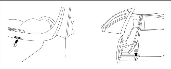
1. VIN plate (visible through windshield) |
2. Vehicle certification plate (lower center pillar) |
8
1-3 Warning and Indicator Lamp Information
|
|
|
|
AAYIA0010GB |
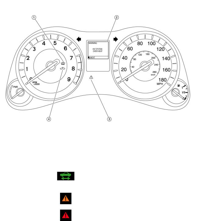
1. |
READY Indicator (Green) |
|
2. HV System Overheat Warning (Dot Matrix Liquid |
|
|
|
|
|
Crystal Display) |
3. |
Master Warning Lamp (Orange or Red) |
4. Hybrid System Warning Lamp (Orange) |
||
|
|
|
|
|
|
Lamp Name |
|
Icon |
Description |
READY Indicator |
|
|
This lamp is on when the high voltage system is powered |
|
(Green) |
|
|
up and the vehicle is ready to drive. |
|
|
|
|
|
|
Master Warning Lamp |
|
|
This lamp is on when another warning lamp or message is |
|
(Orange or Red) |
|
|
displayed in the instrument cluster. |
|
|
|
|
|
|
9

Lamp Name |
Icon |
Description |
Hybrid System Warning |
|
This lamp is on or blinking when: |
Lamp *1 |
|
• Malfunction has occurred in the high voltage system |
(Orange) |
|
and/or |
|
|
• High voltage leak to vehicle chassis and/or |
|
|
• Emergency shut-off system has been activated. The |
|
|
shut-off system activates in the following conditions: |
|
|
– Front and side collisions in which the air bags are |
|
|
deployed. |
|
|
– Certain rear collisions. |
|
|
– Certain high voltage system malfunctions. |
|
|
|
*1: When this lamp is ON, the READY Indicator will turn OFF.
10
2. Basic High Voltage Information
2-1 Battery Information
The M35h HYBRID utilizes two batteries in order to supply both high and low voltage.
2-1.1 12V Battery
•The M35h HYBRID contains a conventional lead-acid 12V battery.
•The 12V battery is located in the trunk, left of Li-ion battery, concealed by trim cover.
•The 12V battery is charged by the Li-ion battery through the DC/DC converter.
AAYIA0064ZZ
2-1.2 Li-ion Battery
•The M35h HYBRID contains a Li-ion high voltage battery.
•The high voltage battery is mounted in the trunk area behind the rear seat, enclosed in a metal case and concealed by trim cover.
•The high voltage battery stores approximately 346 volts DC (400V max.).
•The high voltage battery exhausts gases directly outside the vehicle through a vent hose.
AAYIA0065ZZ
•An air vent is located on the rear parcel shelf for battery cooling.
AAYIA0066ZZ
The high voltage battery supplies power to the following:
•High voltage harnesses
•DC/DC converter
•Traction motor inverter
•Traction motor
•Electric air conditioner compressor
11

2-2 High Voltage-Related and 12V-Related Component Locations and
Descriptions
AAYIA0006ZZ
NOTE:
Components with white number in black background are high voltage components.
12
No. |
|
Component |
Location |
|
Description |
A |
|
Lithium-ion (Li-ion) |
Trunk area (behind |
|
The Li-ion battery stores and outputs DC |
|
|
Battery |
rear seat back) |
|
power (Maximum voltage 400V) needed to |
|
|
|
|
|
propel the vehicle. |
|
|
|
|
|
|
B |
|
DC/DC Converter |
Trunk area (mounted |
|
The DC/DC converter reduces the voltage of |
|
|
|
to top of Li-ion bat- |
|
the Li-ion battery to provide power to the 12V |
|
|
|
tery) |
|
battery in order to operate the vehicle’s electric |
|
|
|
|
|
components (headlights, audio system, etc.). |
|
|
|
|
|
|
C |
|
Service Plug |
Trunk area (below |
|
This is used to disable the high voltage system. |
|
|
|
parcel shelf; behind |
|
|
|
|
|
access door in trim |
|
|
|
|
|
panel) |
|
|
|
|
|
|
|
|
D |
|
12V Battery |
Trunk area (below |
|
A lead-acid battery that supplies power to the |
|
|
|
parcel shelf; behind |
|
low voltage devices. |
|
|
|
trim panel left of |
|
|
|
|
|
Li-ion battery) |
|
|
|
|
|
|
|
|
E |
|
High Voltage Har- |
Trunk area (on Li-ion |
|
Orange-colored power cables carry high DC |
|
|
nesses |
battery), under floor |
|
voltage between each of the high voltage com- |
|
|
|
pan, engine com- |
|
ponents. |
|
|
|
partment |
|
|
|
|
|
|
|
|
F |
|
Electric Air Condi- |
Engine compart- |
|
Air conditioner compressor |
|
|
tioner Compressor |
ment (front driver |
|
|
|
|
|
side) |
|
|
|
|
|
|
|
|
G |
|
Traction Motor |
Engine compart- |
|
Converts the DC power stored in the Li-ion |
|
|
Inverter |
ment (rear passen- |
|
battery to three-phase AC power and controls |
|
|
|
ger side) |
|
motor torque (revolution) by regulating the |
|
|
|
|
|
motor current. The inverter has a built in high |
|
|
|
|
|
voltage capacitor. |
|
|
|
|
|
|
H |
|
Traction Motor |
Built-into the trans- |
|
Converts three-phase alternating current (AC) |
|
|
|
mission |
|
power to drive power (torque) which propels |
|
|
|
|
|
the vehicle. |
2-3 |
Li-ion Battery Pack Specifications |
|
|
||
|
|
|
|
|
|
|
|
|
Li-ion Battery Specifications |
||
Li-ion battery voltage |
|
346V (400V max.) |
|||
|
|
||||
Number of Li-ion battery modules in the pack |
12 |
||||
|
|
|
|||
Li-ion battery module voltage |
|
28.8V each |
|||
|
|
|
|||
Li-ion battery dimensions |
|
33.35 x 17.83 x 15.43 in. (847 x 453 x 392 mm) |
|||
|
|
|
|||
Li-ion battery weight |
|
121.28 lbs (55 kg) |
|||
13
2-4 High Voltage Safety Measures
Circuit insulation |
The high voltage positive (+) and negative (-) circuits are insulated |
|
from the metal chassis. |
|
|
Reducing the risk of electrocution |
The high voltage components and harnesses have insulated cases or |
|
orange-colored coverings which provide insulation and easy identifica- |
|
tion. |
|
The high voltage battery case is electrically connected to the vehicle |
|
ground. This connection helps protect the vehicle occupants and |
|
vehicle dismantlers from high voltage electrical shock. |
|
|
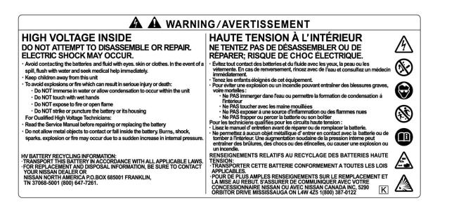
Identification |
The high voltage components are labeled “WARNING” similar to label |
|
shown below. All high voltage harnesses are coated in orange. |
2-4.1 Warning Label |
|
AAYIA0010ZZ
14
2-5 High Voltage Safety System
The high voltage safety system is intended to help keep vehicle occupants and emergency responders safe from high voltage electricity.
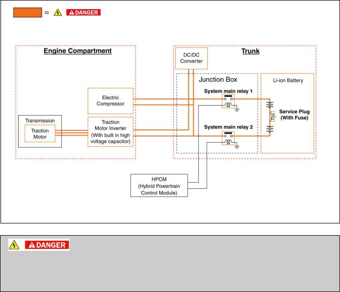
•A high voltage fuse provides short circuit protection inside the high voltage battery.
•The high voltage safety system is insulated from the metal chassis.
•Positive and negative high voltage power cables are connected to the high voltage battery and are controlled by normally open system main relays (SMR1 and SMR2). When the vehicle is shut off, the relays stop electrical flow from leaving the high voltage battery. However, it can take up to
ten (10) minutes for the high voltage capacitor to fully discharge.
AAYIA0001GB
•The high voltage system and high voltage capacitor may remain powered for up to 10 minutes after the vehicle is shut off.
•The high voltage battery retains high voltage at all times.
•A ground fault monitor continuously monitors for high voltage leakage to the metal chassis while the
vehicle is running. If a malfunction is detected, the HPCM (hybrid powertrain control module) will illuminate the hybrid system warning lamp  in the instrument cluster.
•The high voltage battery relays (SMR1 and SMR2) will automatically open to stop the electrical flow in a frontal collision that is sufficient enough to activate the supplemental restraint system (SRS).
15
2-6 High Voltage Circuit Shut-Off System
This vehicle is equipped with a system to shut off the current from the Li-ion battery by the following methods:
Service plug |
Positioned in the center area of the Li-ion battery, this plug shuts off the out- |
|
put of high voltage when manually removed. |
|
|
System main relays |
Controlled by the ignition switch, these relays are powered by the 12V sys- |
|
tem and shut off high voltage from the Li-ion battery. |
|
|
Emergency shut-off sys- |
In the case of a collision (air bag deployment, etc.) or certain system malfunc- |
tem |
tions this system shuts off the high voltage from the Li-ion battery. |
2-7 Preventing Electrical Shock
1.If it is necessary to touch any of the high voltage harnesses or components, always wear appropriate PPE (refer to 3-1 Preparation Items). Shut off the high voltage system by referring to 3-3.1 High Voltage System Shut-Down Procedure.
2.To avoid the risk of electrocution, do not touch the inside of the Li-ion battery with bare hands after shutting off the high voltage system. The Li-ion battery maintains charge even though the high voltage system is shut down.
3.Cover damaged high voltage components with insulated tape.
16
Loading...