

Page 1
SUPPLEMENT TO THE MDC-360C MANUAL
MDC-361C
Film Deposition Controller
IPN 624811 Rev. C
Page 2

Page 3

SUPPLEMENT TO THE MDC-360C MANUAL
MDC-361C
Film Deposition Controller
IPN 628411 Rev. C
®
www.inficon.com reachus@inficon.com
Due to our continuing program of product improvements, specifications are subject to change without notice.
©2007 INFICON
Page 4

Trademarks
The trademarks of the products mentioned in this manual are held by the companies that
produce them.
INFICON® is a trademark of INFICON Inc.
All other brand and product names are trademarks or registered trademarks of their respective companies.
Disclaimer
The information contained in this manual is believed to be accurate and reliable. However, INFICON assumes
no responsibility for its use and shall not be liable for any special, incidental, or consequential damages related
to the use of this product.
Disclosure
The disclosure of this information is to assist owners of INFICON equipment to properly operate and maintain
their equipment, and does not constitute the release of rights thereof. Reproduction of this information and
equipment described herein is prohibited without prior written consent from INFICON, Two Technology Place,
East Syracuse, NY 13057-9714. Phone 315.434.1100. See www.inficon.com.
Copyright
©2004 All rights reserved.
Reproduction or adaptation of any part of this document without permission is unlawful.
First Edition, Rev. A March 2004
Rev. B February 2006
Rev. C October 2007
General Safety Warning
WARNING
All standard safety procedures associated with the safe
handling of electrical equipment must be observed. Always
disconnect power when working inside the controller. Only
properly trained personnel should attempt to service the
instrument.
Page 5

DECLARATION
OF
CONFORMITY
This is to certify that this equipment, designed and manufactured by:
INFICON Inc.
Two Technology Place
East Syracuse, NY 13057
USA
meets the essential safety requirements of the European Union and is placed on the market accordingly. It
has been constructed in accordance with good engineering practice in safety matters in force in the
Community and does not endanger the safety of persons, domestic animals or property when properly
installed and maintained and used in applications for which it was made.
Equipment Description: MDC-361C Thin Film Deposition Controllers (Black Box), including the SO-
100 Oscillator Package.
Applicable Directives: 73/23/EEC as amended by 93/68/EEC (LVD)
89/336/EEC as amended by 93/68/EEC (EMC)
2002/95/EC (RoHS)
Applicable Standards: EN 61010-1:2001 (Safety)
EN 61326-1:1997/A1:1998/A2:2001, Class A: Emissions per Table 3
Immunity per Table A.1
Due to the classification of this product it is currently exempt from the RoHS
directive.
CE Implementation Date: November 1, 2007
Authorized Representative: Duane H. Wright
Quality Assurance Manager, ISS
INFICON Inc.
ANY QUESTIONS RELATIVE TO THIS DECLARATION OR TO THE SAFETY OF INFICON'S PRODUCTS SHOULD BE DIRECTED,
IN WRITING, TO THE QUALITY ASSURANCE DEPARTMENT AT THE ABOVE ADDRESS.
10/01/07
Page 6

Page 7

Warranty
INFICON warrants the product to be free of functional defects in material and
workmanship and that it will perform in accordance with its published specification
for a period of (twenty-four) 24 months.
The foregoing warranty is subject to the condition that the product be properly
operated in accordance with instructions provided by INFICON or has not been
subjected to improper installation or abuse, misuse, negligence, accident,
corrosion, or damage during shipment.
Purchaser's sole and exclusive remedy under the above warranty is limited to, at
INFICON's option, repair or replacement of defective equipment or return to
purchaser of the original purchase price. Transportation charges must be prepaid
and upon examination by INFICON the equipment must be found not to comply
with the above warranty. In the event that INFICON elects to refund the purchase
price, the equipment shall be the property of INFICON.
This warranty is in lieu of all other warranties, expressed or implied and
constitutes fulfillment of all of INFICON's liabilities to the purchaser. INFICON
does not warrant that the product can be used for any particular purpose other
than that covered by the applicable specifications. INFICON assumes no liability in
any event, for consequential damages, for anticipated or lost profits, incidental
damage of loss of time or other losses incurred by the purchaser or third party in
connection with products covered by this warranty or otherwise.
www.inficon.com reachus@inficon.com
Page 8

iv
Page 9

Table of Contents
1. INTRODUCTION.................................................................................................................1
2. COMPUTER INTERFACES...............................................................................................1
3. DISPLAY DESCRIPTION...................................................................................................1
3.1 RS-232/RS-485 INDICATORS...............................................................................................1
3.2 IEEE-488 INDICATORS........................................................................................................2
3.3 STATUS INDICATORS............................................................................................................2
3.4 MANUAL CONTROL .............................................................................................................2
4. INITIAL POWER UP INDICATION.................................................................................3
5. OPERATION.........................................................................................................................3
6. REFERENCES:.....................................................................................................................3
v
Page 10

Page 11

1. INTRODUCTION
This supplement is to be used with the MDC-360C Manual. Its intention is to point out
the differences between the MDC-360C and the MDC-361C. Information supplied
herein is either a replacement or addition to the MDC-360C Manual.
The MDC-361C Deposition Controller was designed for users who want to interface to
the controller solely through a computer. The MDC-361C is a black box version of the
MDC-360C Controller, meaning an MDC-360C with all of the front panel displays and
keys removed. The users can either create their own computer software for a custom
interface or purchase INFICON's DCM-250 computer software to provide complete
computer control of the deposition process.
The key point to emphasize here is, since the MDC-361C is a black box, there is no user
interface on the front panel. All functions are provided through the computer interface.
2. COMPUTER INTERFACES
The MDC-361C is equipped standard with an RS-232 serial interface through a 9-pin DSub located on the rear panel. Optionally, RS-485 and IEEE-488 interfaces are available.
Refer to Section 10 of the MDC-360C Manual for details on communication protocol of
these interfaces.
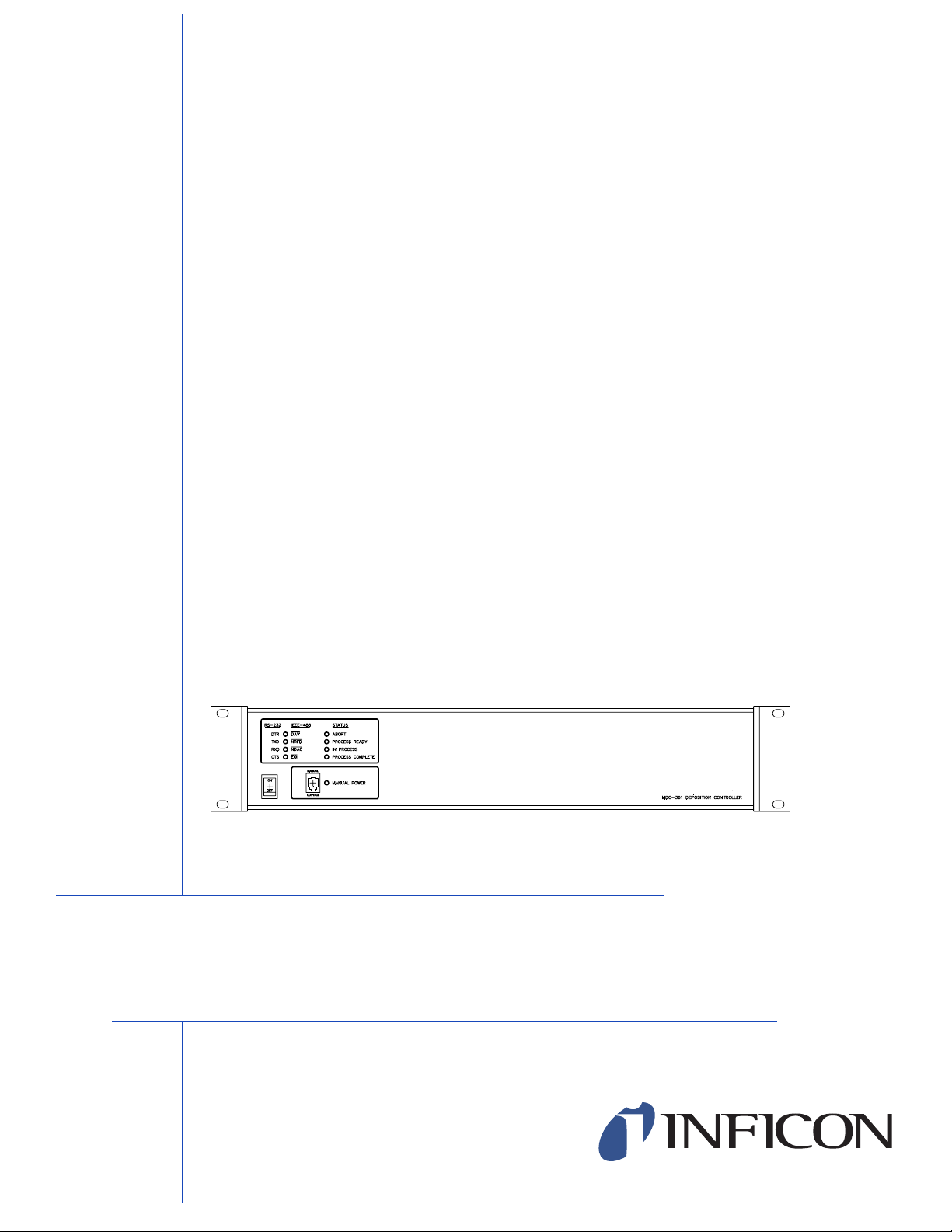
3. DISPLAY DESCRIPTION
Minimal indicators are provided on the MDC-361C front panel. There are four LED’s
displaying the data exchange status between the MDC-361C and the computer. Also,
there are four indicators displaying the MDC-361C’s status. The front panel indicators
are described below.
3.1 RS-232/RS-485 INDICATORS
RTS (Request to Send)
Indicates the host is permitting the MDC-361C to transmit data.
TxD (Transmit Data)
Indicates data being transmitted from the MDC-361C to the host. This LED will briefly
flash each time the 361C sends data to the host.
RxD (Receive Data)
1
Page 12

Indicates the MDC-361C is receiving data from the host. This LED will briefly flash each
time the 361C receives data from the host.
CTS (Clear to Send)
Indicates the MDC-36
1C is ready to receive data. This LED should always be on unless
the host is sending data too fast.
3.2 IEEE-488 INDICATORS
DAV (Data valid)
Indicates that the d
ata on the bus is valid.
NRFD (Not ready for data)
Indicates that the 361C is no
t ready to receive data. This LED should always be on
unless the host is sending data too fast.
NDAC (Not data accepted)
Indicates that the data was n
ot accepted.
EOI (End or identify)
Indicates the end of a m
ulti-byte data transfer.
3.3 STATUS INDICATORS
Abort – Indicates that the controller is
in the abort mode. In this mode, all source powers
are set to zero and discrete outputs are disable. To exit the abort mode a Reset command
has to be sent to the controller.
Process Ready – Indicates that t
he controller has been reset from an abort condition and
is in the Ready State. The controller is awaiting a Start command to run a process.
In Process – Indicates that the controller is running a process. The controller will re
main
In Process until the process has either been aborted and reset or completed.
Process Complete – Indicates that the selected process has run to completion
. The
controller will remain in this mode until it receives a reset command.
3.4 MANUAL CONTROL
In addition to the indicators, a 4 posi
tion RJ-11 connector is provided for connection to
the Remote Power Handset. The Remote Power Handset provides for manual adjustment
of the active source power level, a remote abort command and a manual crystal switch
command.
To manually
Power indicated by the Manual Power LED on the front panel. Note that Manual mode
adjust the active source power, the 361 must first be put into the Manual
has to be selected through software since there are no keys on the MDC-361C front
panel. Depress the “+” button to increase the source control power, depress the “– “
button to decrease the power. Without any of the buttons depressed, the output powe
r is
maintained at its last value.
2
Page 13

Depress the “ABORT” button to put the controller in the Abort mode. This “ABORT”
button is active at all times, regardless which mode the controller is in. Therefore it can
be used as a “panic button”.
To manually switch between the primary and backup sensor/crystal settings for the
current material, press both the “+” and "-" buttons at the same time while the 361C
in the Manual Power Mode. If the primary sensor/crystal is in use, the 361C will switch
to the backup sensor/crystal. If the backup sensor/crystal is already in use then the 361C
will switch to the next crystal for the backup sensor if one is available. If not, the 361C
will switch back to the primary sensor/crystal.
is not
4. INITIAL POWER UP INDICATION
Upon power up, all LED’s turn on for a few seconds then turn off. The Abort LED will
remain on until a reset command is sent to the MDC-361C. The CTS LED will also
remain on indicating the controller is ready to receive data.
5. OPERATION
All operating functions including programming of the MDC-361C is done through one of
the available computer interface.
If you purchased a copy of the DCM-250 software, refer to its manual on how to operate
the software to control your MDC-361C.
If you decided to write your own software to interface with the MDC-361C, please refer
to Section 10 of the MDC-360C Manual for details on communication protocol. Also
refer to the programming and operating sections of the MDC-360C manual to familiarize
yourself with the MDC-360/361C's programming and operation before you write your
interface software. Keep in mind that your software has to provide a complete user
interface for the operators including error messages, warning messages and operator
intervention messages such as layer complete and change source pocket requests. For
example, the 360/361C can be setup to prompt the operator to change the source pock of
a multi-pocket source. So, your software must recognize this request, alert the operator
and signal the 361C that it is OK to continue.
6. REFERENCES:
For other topics such as specifications, installation, maintenance, etc. please refer to the
MDC-360C Manual.
3
Page 14

 Loading...