

Page 1
Translation of the original operating instructions
LDS3000, LDS3000 AQ
Mass spectrometer module
560-300, 560-600
From software version:
MS-Modul 2.71
jiqa54en1-07-(1803)
Page 2

INFICON GmbH
Bonner Strasse 498
50968 Cologne, Germany
Page 3

INFICON Table of Contents
Table of Contents
1 About these instructions ...................................................................................................................................7
1.1 Other associated documents ....................................................................................................................7
1.2 Target groups ...........................................................................................................................................7
1.3 Warnings...................................................................................................................................................7
1.4 Definition of terms.....................................................................................................................................8
2 Safety .............................................................................................................................................................11
2.1 Intended use ...........................................................................................................................................11
2.2 Owner requirements ...............................................................................................................................11
2.3 Duties of the operator .............................................................................................................................12
2.4 Dangers ..................................................................................................................................................12
3 Shipment, Transport, Storage ........................................................................................................................14
4 Description......................................................................................................................................................15
4.1 Function ..................................................................................................................................................15
4.2 Device setup ...........................................................................................................................................16
4.2.1 Entire device (LDS3000)............................................................................................................. 16
4.2.2 Entire device (LDS3000 AQ)....................................................................................................... 16
4.2.3 Connection block ........................................................................................................................ 20
4.2.4 MSB box ..................................................................................................................................... 20
4.2.5 Nameplate................................................................................................................................... 23
4.3 Technical data ........................................................................................................................................24
4.4 Factory settings ......................................................................................................................................25
5 Mounting LDS3000.........................................................................................................................................28
5.1 Adjust the position of the connections to the installation dimensions .....................................................28
5.2 Installing the mass spectrometer module on the test system .................................................................29
5.3 Select connection ULTRA, FINE, or GROSS .........................................................................................30
5.4 Establish component connection ............................................................................................................31
5.5 Establish electrical connections..............................................................................................................32
6 Mounting LDS3000 AQ (Accumulation)..........................................................................................................33
6.1 Adjust the position of the connections to the installation dimensions .....................................................33
6.2 Installing the mass spectrometer module on the test system .................................................................34
6.3 Select components and connect.............................................................................................................36
6.4 Establish electrical connections..............................................................................................................38
7 Operation LDS3000........................................................................................................................................39
LDS3000-MSM-Operating-instructions-jiqa54en1-07-(1803) iii
Page 4

Table of Contents INFICON
7.1 Switching the device on ..........................................................................................................................39
7.2 Default settings .......................................................................................................................................40
7.3 Selecting a unit for the leak rate .............................................................................................................42
7.4 Select device for pressure ......................................................................................................................43
7.5 Select Compatibility Mode ......................................................................................................................43
7.6 Select operation mode............................................................................................................................45
7.7 Select gas type (mass) ...........................................................................................................................46
7.8 Calibrating the device .............................................................................................................................47
7.8.1 Time and general preferences ....................................................................................................47
7.8.2 Internal Calibration Configuration and Start................................................................................ 49
7.8.3 External Calibration Configuration and Start............................................................................... 50
7.8.4 Start external dynamic calibration............................................................................................... 52
7.8.5 External calibration with sniffer line SL3000XL........................................................................... 54
7.8.6 Check the calibration .................................................................................................................. 55
7.8.6.1 Calibration using the internal calibration leak test..............................................................55
7.8.6.2 Calibration using the external calibration leak test.............................................................55
7.8.7 Entering the calibration factor .....................................................................................................56
7.8.7.1 Calibration factor sniffing....................................................................................................56
7.8.7.2 Calibration factor vacuum ..................................................................................................56
7.8.8 Setting machine and sniff factor.................................................................................................. 57
7.8.8.1 Setting machine and sniff factor manually .........................................................................57
7.8.8.2 Setting machine and sniff factor using machine calibration ...............................................58
7.9 Starting and stopping the measurement.................................................................................................58
7.10 Loading and saving parameters .............................................................................................................59
7.11 Copying measurement data, deleting measurement data ......................................................................60
7.12 Suppressing gas backgrounds with "ZERO" functions ...........................................................................60
7.13 Measurement result display with signal filters ........................................................................................61
7.14 Control of the Gas Ballast Valve of the Backing Pump...........................................................................62
7.15 Selecting display limits............................................................................................................................63
7.16 Setting trigger values ..............................................................................................................................63
7.17 Setting capillary surveillance ..................................................................................................................63
7.18 Set the rotation speed of the turbo molecular pump...............................................................................64
7.19 Cathode Selection ..................................................................................................................................65
7.20 Settings for the XL sniffer adapter ..........................................................................................................65
7.21 Resetting the settings .............................................................................................................................68
8 Operation LDS3000 AQ (Accumulation).........................................................................................................69
8.1 Switching the device on ..........................................................................................................................69
iv LDS3000-MSM-Operating-instructions-jiqa54en1-07-(1803)
Page 5

INFICON Table of Contents
8.2 Default settings .......................................................................................................................................69
8.3 Selecting a unit for the leak rate .............................................................................................................70
8.4 Select device for pressure ......................................................................................................................71
8.5 Select Compatibility Mode ......................................................................................................................71
8.6 Making basic settings via the wizard ......................................................................................................73
8.7 Determine peak ......................................................................................................................................74
8.8 Store leak rate of calibration leaks..........................................................................................................75
8.9 Calibrating the device .............................................................................................................................76
8.9.1 Time and general preferences ....................................................................................................76
8.9.2 Entering the calibration factor .....................................................................................................77
8.9.3 Calibration factor vacuum ...........................................................................................................77
8.9.4 Calibrating................................................................................................................................... 78
8.10 Perform ZERO ........................................................................................................................................80
8.11 Setting machine and sniff factor .............................................................................................................81
8.11.1 Setting machine and sniff factor manually ..................................................................................81
8.12 Carrying out a measurement ..................................................................................................................82
8.13 Loading and saving parameters .............................................................................................................83
8.14 Copying measurement data, deleting measurement data ......................................................................83
8.15 Adjust ”Zero time factor AQ” ...................................................................................................................84
8.16 Selecting display limits............................................................................................................................84
8.17 Set the rotation speed of the turbo molecular pump...............................................................................84
8.18 Cathode Selection ..................................................................................................................................85
8.19 Resetting the settings .............................................................................................................................85
9 Using the expansion module (LDS3000, LDS3000 AQ).................................................................................87
9.1 Selecting the type of expansion module .................................................................................................87
9.2 Settings for I/O module IO1000 ..............................................................................................................87
9.2.1 General interface settings ...........................................................................................................87
9.2.2 Assigning inputs and outputs ......................................................................................................87
9.2.2.1 Assigning the digital inputs of the I/O module ....................................................................95
9.2.2.2 Assigning the digital outputs of the I/O module..................................................................98
9.3 Settings for bus module BM1000..........................................................................................................100
10 Warning and error messages (LDS3000, LDS3000 AQ).............................................................................. 101
10.1 Illustration of error codes with the help of the status LEDs...................................................................109
11 Operating CU1000 (optional)........................................................................................................................ 110
11.1 Touchscreen elements .........................................................................................................................110
11.1.1 Measurement display elements ................................................................................................110
LDS3000-MSM-Operating-instructions-jiqa54en1-07-(1803) v
Page 6

Table of Contents INFICON
11.2 Elements of the error and warning display ...........................................................................................113
11.3 Settings and functions ..........................................................................................................................113
11.3.1 Touch screen settings ............................................................................................................... 113
11.3.2 Operator types and authorizations ............................................................................................ 117
11.3.2.1 Logging out the operator ..................................................................................................118
11.3.3 Functions .................................................................................................................................. 118
11.3.3.1 Resetting the settings.......................................................................................................118
11.3.3.2 Recording data.................................................................................................................119
11.3.3.3 Calling up information ......................................................................................................120
11.3.4 Updating the software ............................................................................................................... 123
11.3.4.1 Updating the software of the control unit..........................................................................123
11.3.4.2 Checking and updating the software version of the MSB box..........................................123
11.3.4.3 Updating the software of the I/O module..........................................................................124
12 Maintenance .................................................................................................................................................126
12.1 Maintenance at INFICON .....................................................................................................................126
12.2 General maintenance information.........................................................................................................126
12.3 Maintenance plan .................................................................................................................................127
12.4 Maintenance work.................................................................................................................................128
12.4.1 Change operating fluid reservoir of turbo molecular pump ....................................................... 128
13 Decommissioning the measuring instrument................................................................................................ 133
13.1 Shutting down the leak detector ...........................................................................................................133
13.2 Disposing of the mass spectrometer module........................................................................................133
13.3 Returning the mass spectrometer module............................................................................................133
14 Appendix....................................................................................................................................................... 134
14.1 CE Declaration of Conformity ...............................................................................................................134
14.2 Declaration of Incorporation..................................................................................................................135
14.3 Declaration of Contamination ...............................................................................................................136
vi LDS3000-MSM-Operating-instructions-jiqa54en1-07-(1803)
Page 7

INFICON About these instructions | 1
1 About these instructions
This document applies to the software version stated on the title page.
Product names may occur in the document, which are added for identification pur-
poses only and belong to the respective owner of the rights.
This operating manual describes the installation and operation of the LDS3000 mass
spectrometer module. It is available in two variants:
• LDS3000
• LDS3000 AQ (accumulation), switchable to all other operating modes.
1.1 Other associated documents
Operating Manual Control Unit CU1000 jina54
Operating instructions bus module jiqb10
Operating instructions I/O module jiqc10
Operating instructions XL sniffer adapter jinxa54
Interface protocols jira54
1.2 Target groups
These operating instructions are intended for the owner and for technically qualified
personnel with experience in leak detection technology and integration of leak detec-
tion devices in leak detection systems. In addition, the installation and use of the de-
vice require knowledge of electronic interfaces.
1.3 Warnings
DANGER
Imminent hazard resulting in death or serious injuries
WARNING
Hazardous situation resulting in potential death or serious injuries
LDS3000-MSM-Operating-instructions-jiqa54en1-07-(1803) 7 / 138
Page 8

1 | About these instructions INFICON
CAUTION
Hazardous situation resulting in minor injuries
NOTICE
Hazardous situation resulting in damage to property or the environment
1.4 Definition of terms
Mention of helium in the manual
The device is a helium leak detector. If you want to use a forming gas instead of he-
lium to detect the hydrogen contained therein, the information for helium also applies
to hydrogen.
Accumulation
In connection with leak testing, it is about the enrichment of tracer gas over a defin-
able period of time. This allows the detection of small leak rates without the use of a
vacuum chamber. Helium or forming gas can be used.
When you talk about "AQ” in this manual, it's about accumulation mode. It is only
available for devices in the AQ version.
Automatic tuning / mass setting
This function adjusts the mass spectrometer so that a maximum leak rate indicator is
achieved. In order to detect a maximum ion current with the ion detector, the control
computer adjusts the voltage for accelerating the ions within the selected mass range
accordingly.
During each calibration, there is an automatic adjusted.
Operation mode
The leak detector distinguishes between the operation modes "vacuum" and "sniffing".
With the operation mode "vacuum", generally the tracer gas flows into the test object.
The pressure in the test object is less than the ambient pressure.
In the operation mode "sniffing" the tracer gas flows out from the test object and is ex-
tracted with a sniffer probe. The pressure in the test object is greater than the ambient
pressure.
8 / 138 LDS3000-MSM-Operating-instructions-jiqa54en1-07-(1803)
Page 9

INFICON About these instructions | 1
FINE
FINE denotes the connection to the turbo molecular pump for inlet pressures up to 0.4
mbar. This is also used for the "sniffing" operation mode.
Forming gas
Forming gas is a collective term for gas mixtures of nitrogen and hydrogen.
GROSS
GROSS donates the connection to the turbo molecular pump with the lowest sensitiv-
ity. This allows high inlet pressures (up to 15 mbar).
Internal helium background
The measurement system of the leak detector also contains a residual amount of he-
lium. This creates an internal measurement signal component (background signal),
which overlaps the display of the leak right from the beginning and thus disturbs the
search for leaks.
So that this background signal can be suppressed, an internal "background suppres-
sion" can be activated with the factory settings.
Minimum detectable leak rate
The minimum detectable leak rate which can be detected by the leak detector under
ideal conditions (< 5 x 10
-12
mbar l/s).
ULTRA
ULTRA denotes the connection to the turbo molecular pump for the measurement
range with the highest sensitivity at inlet pressures below 0.4 mbar (adjustable).
Background signal
Helium or hydrogen (as part of water) are natural components of air.
Operation mode "Vacuum": Before any leak detection, a certain amount of the ad-
justed tracer gas is already in the volume on the surfaces of the test chamber, supply
lines, and even in the leak detector itself. This certain amount of tracer gas generates
a measurement signal which is called the "Background signal". The ongoing evacua-
tion of the test chamber continuously reduces this background signal.
Operation mode "Sniffing": Ambient air is continuously fed into the leak detector via
the sniffer line. The amount of helium or hydrogen occurring naturally in air creates a
constant background signal.
LDS3000-MSM-Operating-instructions-jiqa54en1-07-(1803) 9 / 138
Page 10

1 | About these instructions INFICON
Foreline pressure
Pressure of the backing pressure between the turbo molecular pump and the backing
pump.
ZERO
There is helium that is weakly bound to the surfaces of a specimen as a natural part of
the ambient air and is pumped bit by bit into the measurement system of the leak de-
tector. It produces a slowly decreasing measurement signal.
If you want to hide this background signal or the display of existing leaks, then use the
function ZERO.
10 / 138 LDS3000-MSM-Operating-instructions-jiqa54en1-07-(1803)
Page 11

INFICON Safety | 2
2 Safety
2.1 Intended use
The device is a modular leak detector for installation in industrial leak testing unit sys-
tems. The tracer gases that can be measured with the device are helium and hydro-
gen (forming gas).
The LDS3000 is suitable for overpressure and negative pressure testing, whereby in
addition to the test in vacuum, a local test with a sniffer line is also possible.
The LDS3000 AQ is intended for the measurement of test gases when enriched in an
external measuring chamber, but can also be rebuilt for all other purposes.
► You must install, operate and service the device only in compliance with these oper-
ating instructions.
► Comply with application limits, see "Technical Data".
Improper use
Avoid the following, non-intended uses:
• Use in radioactive areas
• Pumping down of explosive, aggressive, corrosive, flammable, toxic or reactive
substances
• Pumping down of condensable fluids and vapors.
• Aspiration of liquids into the device
• Operation with excessive gas loads
• Operation with excessive foreline pressure
• Operation in incorrect gas mode
• Operation at too high ambient temperature
• Flushing with excessive flushing rate
• Usage of the pumps in plants where sudden loads and vibrations or periodic
forces act upon the pump
2.2 Owner requirements
The following notes are for companies or any person who is responsible for the safety
and effective use of the product by the user, employee or third party.
Safety conscious oper-
ation
LDS3000-MSM-Operating-instructions-jiqa54en1-07-(1803) 11 / 138
• Operate the device only if it is in perfect technical condition and has no damage.
• Only operate the device in accordance with this instruction manual, in a safety and
risk conscious manner.
• Adhere to the following regulations and observe their compliance:
– Intended use
Page 12

2 | Safety INFICON
– General applicable safety and accident prevention regulations
– International, national and local standards and guidelines
– Additional device-related provisions and regulations
• Only use original parts or parts approved by the manufacturer.
• Keep this instruction manual available on site.
Personnel qualifica-
tions
• Only instructed personnel should be permitted to work with and on the device. The
instructed personnel must have received training on the device.
• Make sure that authorized personnel have read and understood the operating in-
structions and all other applicable documents.
2.3 Duties of the operator
• Read, observe, and follow the information in this manual and in the work instruc-
tions provided by the owner. This concerns in particular the safety instructions and
warnings.
• Always observe the complete operating instructions for all work.
• If you have any questions about operation or maintenance that are not answered
in this manual, please contact Customer Service.
2.4 Dangers
The measuring instrument was built according to the state-of-the-art and the recog-
nized safety regulations. Nevertheless, improper use may result in risk to life and limb
on the part of the user or third parties, or damage to the measuring instrument or other
property may occur.
Hazards due to liquids
and chemicals
Permanent magnets
Dangers from electric
power
12 / 138 LDS3000-MSM-Operating-instructions-jiqa54en1-07-(1803)
Liquids and chemical substances can damage the instrument.
• Comply with application limits, see "Technical Data".
• Do not suck up liquids with the instrument.
• Keep the hydrogen concentration below 5% to prevent ignition.
Permanent magnets in the device pose a hazard to health. Cardiac pacemaker may
be affected in their function.
• Keep a sufficient distance from the device.
• Always comply with the distances recommended by the pacemaker manufacturer
without fail.
The device is operated with electrical voltages of up to 24 V. Inside the device there
are voltages that are considerably higher. There is a danger to life from the contact of
conductive parts inside the device.
Page 13

INFICON Safety | 2
• Disconnect the device from the power supply prior to any installation and mainte-
nance work. Make sure that the electric power supply cannot reconnected without
authorization.
• Before starting the leak test, disconnect electrically operated test objects from the
power supply.
The device contains electric components that can be damaged from high electric volt-
age.
• Make sure before connecting to the power supply that the supply voltage is 24 V
+/- 5 %.
Kinetic energy
Injury from bursting ob-
jects
Danger due to implod-
ing measuring chamber
If the rotating parts in the turbo molecular pump are blocked because of some dam-
age, high centrifugal forces must be absorbed. If this is not successful, the mass spec-
trometer module will breakaway and possibly cause damage to property or personal
injury.
• Make sure the mount of the mass spectrometer module is able to absorb a braking
torque of 820 Nm.
There is risk of injury from bursting objects causes by a test object notwithstanding the
vacuum pressure when a test object is connected.
• Take appropriate precautions.
An external measuring chamber connected to an LDS3000 AQ is pumped off at ap-
proximately 60 sccm. Within normal measurement times (2 - 30 seconds) no danger-
ous negative pressure is generated.
If the measuring chamber is leak-proof, but not vacuum resistant, and continues to
pump, it may implode. This can occur, for example, in a 1-liter measuring chamber af-
ter about 10 minutes.
• Do not continue pumping a measuring chamber after the measuring time has ex-
pired.
• Consider suitable protective measures!
LDS3000-MSM-Operating-instructions-jiqa54en1-07-(1803) 13 / 138
Page 14
3 | Shipment, Transport, Storage INFICON
3 Shipment, Transport, Storage
Scope of delivery
Transport
Item Quantity
Mass spectrometer module
Plug for 24V connection 1
Pressure sensor PSG500 1
Self-locking nuts 4
Plug for Output 1
Plug for Gauges Exit 1
Inlet module (LDS3000 AQ version only) 1
Adapter DN16 with throttle2) (LDS3000 AQ version only) 1
Operating instructions 1
USB flash drive with instructions, 3D drawings and videos 1
1.) Includes either 560-300 LDS3000 or 560-600 LDS3000 AQ (accumulation).
2.) See "Select components and connect [}36]".
► Please check the delivery for completeness after receiving the device.
1)
1
Storage
NOTICE
Damage due to unsuitable packaging material
Transport in unsuitable packaging material can damage the device.
► Transport the device only in the original packaging material.
► Keep original packaging material.
NOTICE
Damage to property due to missing attachment of the vibration damper
► Secure the vibration damper with the transport screws to prevent damage due to vi-
bration.
► Always store the device in compliance with the technical data, see "Technical Data".
14 / 138 LDS3000-MSM-Operating-instructions-jiqa54en1-07-(1803)
Page 15

INFICON Description | 4
4 Description
4.1 Function
Objective
Mode AQ (Accumula-
tion)
Device Interfaces
Other accessories
The mass spectrometer module is a detection device for the test gases helium and hy-
drogen. Integrated in test systems, the device is used to detect gas being emitted from
a test object in order to indicate leaks.
The device can be used both as a vacuum leak detector and a sniffer leak detector.
Sniffer lines with different lengths are available for the sniffer mode.
In order to be able to detect small leak rates without the use of a vacuum chamber,
devices for the AQ mode are connected to an external measuring chamber. In the ex-
ternal measuring chamber, the tracer gas is enriched (accumulation).
The test object filled with helium or forming gas under pressure is brought into the
measuring chamber or pressurized in the measuring chamber. If there is a leak in the
test object, the concentration of helium or forming gas in the measuring chamber will
increase. This increase is measured and output as a leak rate.
The mass spectrometer module is part of the leak detection system LDS3000 and
LDS3000 AQ. Es can be operated in a test system together with a bus module or I/O
module and a data cable without additional INFICON accessories.
The MSB box outputs data on digital interfaces to the control unit CU1000, I/O module
IO1000 or bus module BM1000.
With the available accessories XL sniffer adapter and sniffer line SL3000XL, it is pos-
sible to capture leaks at a larger distance from the expected leak if the detection limit
is deteriorated (operation in "high flow" mode).
LDS3000-MSM-Operating-instructions-jiqa54en1-07-(1803) 15 / 138
Page 16
4 | Description INFICON
4.2 Device setup
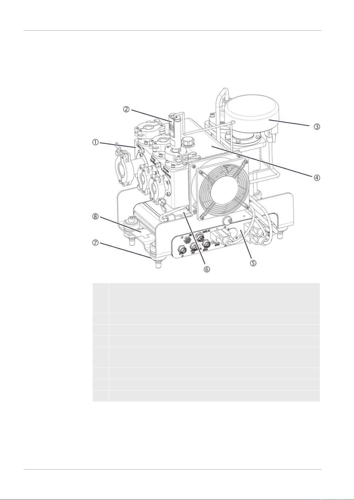
4.2.1 Entire device (LDS3000)
Fig.1:
Mass spectrometer module LDS3000
1 Connection block. Connections for test system, backing pump, pressure sen-
sor PSG500, internal calibration leak and sniffer line, see also "Connection
block [}20]".
2 Pressure sensor PSG500 for measuring the pressure of the backing pump
3 Preamplifier of the mass spectrometer module
4 Turbo molecular pump with cooling unit
5 MSB box. Interfaces to the mass spectrometer module (see "MSB box
[}20]")
6 Inverter for turbo-molecular pump
7 Fasteners for installing the mass spectrometer module in a test system
8 Rating plate containing mass spectrometer module specifications
4.2.2 Entire device (LDS3000 AQ)
In the accumulation version, the mass spectrometer module is integrated into a spe-
cial measurement setup by hardware and software.
16 / 138 LDS3000-MSM-Operating-instructions-jiqa54en1-07-(1803)
Page 17
INFICON Description | 4
3
1
2
6
7
1
4
5
48
49
4
11
4
10
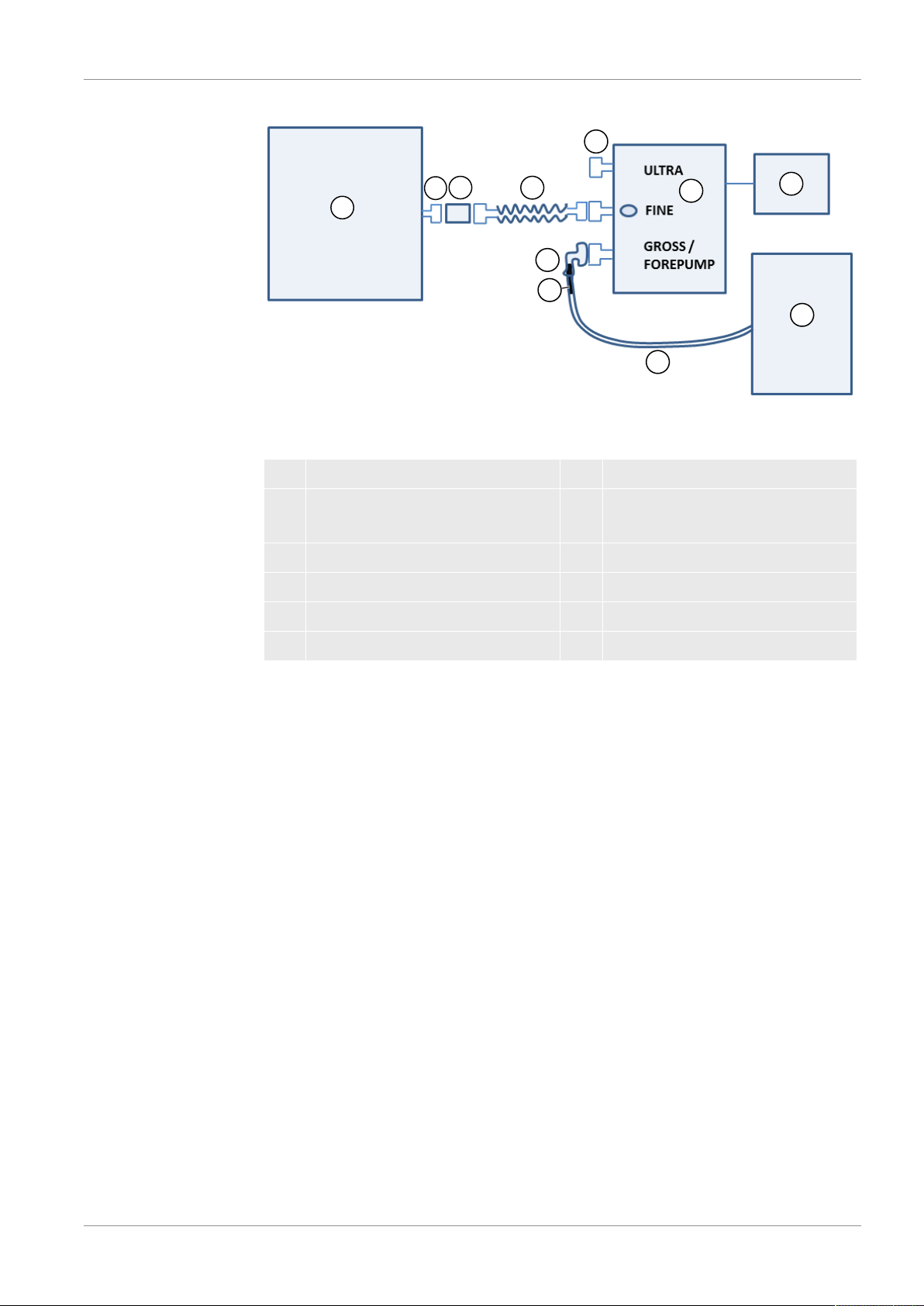
Fig.2:
Accumulation: Overview of the structure
1 Measuring chamber with fan 7 Power supply 24 V
2 ISO-KF DN16 8 Dry backing pump with separate
power supply)
3 Inlet module 9 Hose ID 10
4 Corrugated tube 10 Straight connector 8 to 10 mm
5 Blank flange 11 Adapter to DN16
6 Mass spectrometer module
LDS3000-MSM-Operating-instructions-jiqa54en1-07-(1803) 17 / 138
Page 18

4 | Description INFICON
2
1
3
34
Fig.3:
Mass spectrometer module (execution accumulation)
1 Pressure sensor PSG500 for mea-
2 Connecting hose to backing pump
suring the inlet pressure
3 Corrugated hose to the measuring
4 Flanged ULTRA connections
chamber
Fig.4:
Inlet module. It does not require an electrical connection for connection to a measuring
chamber.
When using a two-chamber system, the inlet module valve can be switched by applying 24V.
1 For connection to the measuring chamber
Accessories of the cus-
tomer
To complete the measurement setup, missing parts can be provided by the customer.
If you want to use your own backing pump, make sure it is a dry backing pump with a
gas flow greater than 60 sccm and a base pressure of less than 5 mbar. It should
have its own power supply.
18 / 138 LDS3000-MSM-Operating-instructions-jiqa54en1-07-(1803)
Page 19

INFICON Description | 4
Connection for hose ID 10 mm
Connection for silencer (optional)
Connection Plus (24 V)
Connection minus
If you want to use your own control unit, please note that the wizard for performing the
measurement settings, calibrating and setting the ZERO function is only located on
the INFICON CU1000 control unit.
See also “Select components and connect [}36]“.
Optional accessories
from INFICON
With the exception of the measuring chamber, the required parts are also offered by
INFICON.
• Control unit CU1000 (including wizard for carrying out important settings)
• I/O1000 (The I/O module is a device interface between a leak detector and an ex-
ternal controller)
• BM1000 (The bus module is a device interface between e.g. the MSB box of the
mass spectrometer module LDS3000 and an external controller.)
• Dry backing pump from INFICON (catalog number 560-630)
LDS3000-MSM-Operating-instructions-jiqa54en1-07-(1803) 19 / 138
Fig.5:
INFICON backing pump
See also
2 Entire device (LDS3000) [}16]
Page 20

4 | Description INFICON
4.2.3 Connection block
Fig.7:
MSB box connections
Fig.6:
Connection block
1 Connection ULTRA 3 Connection GROSS/FOREPUMP
2 Connection FINE/SNIFFER
4.2.4 MSB box
OUTPUT
Connection for gas ballast and three valves
Connection plug arrangement
1 Valve 2 (gas ballast), 24 V, max.1 A
2 Valve 3 (not used, reserve)
3 Valve 4 (not used, reserve)
4 Valve 6 (not used, reserve)
5 GND
SNIFFER
Electrical connection for the sniffer line
20 / 138 LDS3000-MSM-Operating-instructions-jiqa54en1-07-(1803)
Page 21

INFICON Description | 4
GAUGES, EXT
Connection for optional external service gauges (0 - 10 V / 0 - 20 mA) for INFICON
service
Connection plug arrangement
1 +24-V-Output, max.200 mA
2 Input for P3 service gauge, 0 - 10 V
3 GND
4 Reference to input for P3 service gauge
5 20 mA input for P3 service gauge
1
(See also Figure MSB box)
Connection for pressure sensor PSG500, calibration leak and suppressor on the
preamplifier (premounted, three-core cable)
24VDC
Connection for 24 V power supply pack used to supply mass spectrometer module,
control unit, I/O module and bus module.
2
(See also Figure MSB box)
Connection for inverter turbo molecular pump and fan turbo molecular pump (pre-
mounted, two-core cable)
ON SOURCE
I
Connection for ion source
3
(See also Figure MSB box)
Connection for preamplifier
Power LED
/ Status LED
The Power LED and Status LED indicate the status of the device.
Power LED Status LED Meaning
Off Red Device not ready for operation
Green Blue Turbo molecular pump is starting
Green Orange Emission is switched on
Green Green Emission is stable
LDS3000-MSM-Operating-instructions-jiqa54en1-07-(1803) 21 / 138
Page 22

4 | Description INFICON
Power LED Status LED Meaning
Green Violet Rotation speed of the turbo molecular
pump is not within the normal range
Green Error codes of
Different activities of the unit
the status LED
Green, flashes slowly Supply voltage < 21.6 V
Green, flashes fast Supply voltage > 26.4 V
Green, flashes Off Software is being updated
Green Green, flashes Software is being updated
SERVICE
RS232 connection for INFICON Service
I/O / ANYBUS
CONTROL UNIT
Connection for I/O or bus module or control unit
The connections "I/O Anybus" and "Control Unit" have the same functions. You have
the choice of connecting:
– Control unit CU1000 + I/O module IO1000
– Control unit CU1000 + bus module BM1000
STATUS
Status LED
The Power LED and Status LED indicate the status of the unit.
22 / 138 LDS3000-MSM-Operating-instructions-jiqa54en1-07-(1803)
Page 23

INFICON Description | 4
4.2.5 Nameplate
A nameplate is located on the device. The symbols on the nameplate have the follow-
ing meaning:
Label for the returns to the recycling circuit.
Instrument cannot be scrapped with the normal domestic waste.
Information given on the nameplate are:
• Manufacturer's address
• Device name
• Year of production
• Catalog number
• Serial number
• Operating temperature
• Disposal instructions
• Detectable gases
LDS3000-MSM-Operating-instructions-jiqa54en1-07-(1803) 23 / 138
Page 24

4 | Description INFICON
4.3 Technical data
Mechanical data
Electrical data
560-300, 560-600
Power input max. 10 A
Physical data
560-300, 560-600
Response time in Sniffer mode Gross: < 5 s, Fine/Ultra: < 1 s
Maximum inlet pressure 0,2 mbar - 18 mbar
Run-up time 150 s
Detectable gases Helium, hydrogen
Minimum detectable leak rate vacuum
mode
Minimum detectable leak rate sniffer
mode
Detectable masses 4He, H2, mass 3 (e.g. H-D, 3He or H3)
Ion source 2 longlife Iridium filaments, Yttrium-oxide
Minimum detectable leak rate forming
gas or helium
Measurement range 6 decades
Pressure in test chamber 1 atm
Time constant of the leak rate signal < 1 s
5E-12 mbar l/s
1E-7 mbar l/s
coated
560-600 (AQ mode)
1 x 10⁻⁷ mbar l/s
Ambient conditions
560-300, 560-600
Permissible ambient temperature (during
operation)
Max. altitude above sea level 2000 m
Permissible magnetic field max. 7 mT
Max. relative humidity above 40 °C 50%
24 / 138 LDS3000-MSM-Operating-instructions-jiqa54en1-07-(1803)
10 °C ... 45 °C
Page 25

INFICON Description | 4
560-300, 560-600
Max. relative humidity from 31 °C to 40°C80% ... 50% (decreasing linearly)
Max. relative humidity to 40 °C 80%
Storage temperature -20 °C ... 60 °C
Pollution degree II
4.4 Factory settings
Parameter Factory setting
AO upper limit exp. 1 x 10
-5
Operation mode Vacuum
1)
AQ
AQ chamber volume 1 l
AQ measurement time 10 s
Zero time factor AQ 4
1)
1)
1)
Bus module address 126
Clogged pressure capillary monitoring
- with XL Sniffer Adapter (low flow)
Broken pressure capillary monitoring
- with XL Sniffer Adapter (low flow)
0.4 mbar
0.2 mbar
2 mbar
0.6 mbar
Clogged pressure capillary monitoring
- with XL Sniffer Adapter (high flow) 150 mbar
Broken pressure capillary monitoring
- with XL Sniffer Adapter (high flow) 400 mbar
Pressure unit (interface) mbar
Emission On
Filter leak rate threshold 1 x 10
-10
Filter ZERO time 5 s
Filter mode I•CAL
Gas percentage in H2 (M3, He) 100 %
5 % H2 (-, 100 % He)
1)
Gas ballast Off
I/O module protocol ASCII
Calibration request On
Calibration factor VAC/SNIF Mx
1.0
(for vacuum, sniffing and all masses)
Cathode selection Auto Cat1
LDS3000-MSM-Operating-instructions-jiqa54en1-07-(1803) 25 / 138
Page 26

4 | Description INFICON
Parameter Factory setting
Compatibility mode LDS3000
1)
AQ
Config. Analog output 1 Leak rate mantissa
Config. Analog output 2 Leak rate exponent
Config. Analog output scale 0.5 V / decade
Configuration of digital outputs Pin 1: Trigger 1, inverted
Pin 2: Trigger 2, inverted
Pin 3: Trigger 3, inverted
Pin 4: Trigger 4, inverted
Pin 5: Ready
Pin 6: Error, inverted
Pin 7: CAL request, inverted
Pin 8: Open, inverted
Configuration of digital Inputs Pin 1: Select dyn. / normal CAL
Pin 2: Sniff
Pin 3: Start/Stop, inverted
Pin 4: ZERO
Pin 5: External CAL
Pin 6: Internal CAL
Pin 7: Clear
Pin 8: ZERO update
Pin 9: –
Pin 10: –
Leak rate unit SNIF, (display and inter-
mbar l/s
face)
Leak rate unit VAC, (display and inter-
mbar l/s
face)
Leak rate upper limit VAC (interface) 1.0 x 10
Leak rate lower limit VAC (interface) 1.0 x 10
Leak rate upper limit SNIF (interface) 1.0 x 10
Leak rate lower limit SNIF (interface) 1.0 x 10
4
-12
4
-8
Fan mode Fan always on
Machine factor in standby Off
Machine factor / Sniff factor 1.0 (for all masses)
Mass 4
Module on the I/O connection IO1000
Nominal state TMP On
calibration leak external SNIF 9.9 x 10
calibration leak external VAC 9.9 x 10
-2
-2
26 / 138 LDS3000-MSM-Operating-instructions-jiqa54en1-07-(1803)
Page 27

INFICON Description | 4
Parameter Factory setting
calibration leak internal 9.9 x 10
-2
Open calibration leak internal Off
Sniffer line detection On
Sniffer key ZERO On
Language English
TMP rotation speed 1500
1)
1000
Trigger level 1 (2, 3, 4) 1 x 10⁻⁵ mbar l/s
5 x 10⁻⁵ (1 x 10⁻⁵) mbar l/s
Preamplifier test at CAL On
Maintenance warning Off
ZERO with start Off
ZERO mode Suppress everything
1) in AQ mode
1)
LDS3000-MSM-Operating-instructions-jiqa54en1-07-(1803) 27 / 138
Page 28

5 | Mounting LDS3000 INFICON
5 Mounting LDS3000
5.1 Adjust the position of the connections to the
installation dimensions
Select location
Select the most helium-free environment possible for the measurement setup. For reli-
able measurements with the device, the helium content in the air must be less than 10
ppm.
By nature, air contains 5 ppm (0.0005%) helium.
Mount MSB box
In order to ideally match the installation position space, the MSB box can be turned
and rotated.
The MSB box is seated in two guide rails and can be pushed into the housing from the
left or from the right. It can also be rotated, if necessary, so that the labels are upside
down.
The locking washer must be released to pull out the MSB box.
If the MSB box is to be pushed into housing from the other side, the locking washer
must also be tightened on the other side of the housing. An appropriate threaded hole
is available.
Fig.8:
Lock
28 / 138 LDS3000-MSM-Operating-instructions-jiqa54en1-07-(1803)
Page 29
INFICON Mounting LDS3000 | 5
5.2 Installing the mass spectrometer module on the
test system
The mass spectrometer module can be mounted in any position.
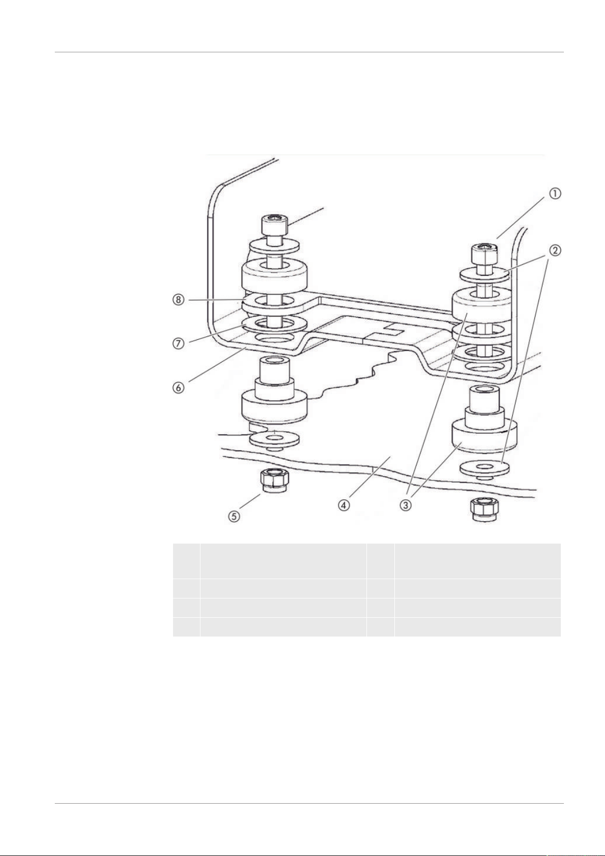
Fig.9:
Components of a fastener
1 Hexagon socket head screw
M8x50
2 Washer 6 Base frame
3 MO bearing 7 Spring rubber
4 Test system 8 MSB box guide
You will need:
- Self-locking nuts M8
- Open-end wrench, SW13
- Allen wrench SW6
- Holes for installation inside the test system
LDS3000-MSM-Operating-instructions-jiqa54en1-07-(1803) 29 / 138
5 Nut M8 (self-locking)
Page 30

5 | Mounting LDS3000 INFICON
In delivery condition, the bearings are attached to the base frame with the hexagon
socket screws and transport nuts. Use the supplied self-locking nuts for the installation
of the mass spectrometer module – not the transport nuts.
The background must be stable.
WARNING
Severe injuries due to mass spectrometer module breaking out
If not screwed down properly, the mass spectrometer module can be caused to break
out if the rotor of the turbo molecular pump suddenly locks up. This can result in in-
juries of the most severe kind.
► Make sure the mount of the mass spectrometer module is able to absorb a braking
torque of 820 Nm.
1
Drill through-holes:
– X distance: 283 mm
– Y-distance: 121,5 mm
– Through hole in sheet: Ø 9 mm
– Fixing screws: M8 x 50
2
Remove transport nuts.
3
Place the mass spectrometer module on top of the through-holes and screw it
down using the fasteners as shown in the upper figure .
5.3 Select connection ULTRA, FINE, or GROSS
The operation mode of the vacuum connection and the rotation speed of the turbo
molecular pump define:
• Minimum detectable leak rate (MDLR)
• Constantly permissible inlet pressure (p
• Pumping speed (S)
The following information applies to the use of helium as a tracer gas.
To reach the MDLR, the following conditions must be met:
• The LDS3000 must be in operation for at least 20 minutes.
• Ambient conditions must be steady (temperature, no vibrations/shocks, clean envi-
ronment)
30 / 138 LDS3000-MSM-Operating-instructions-jiqa54en1-07-(1803)
max
)
Page 31

INFICON Mounting LDS3000 | 5
• The specimen must be operated with switched-off ZERO until to the background is
stable. The ZERO function may be switched on only after that.
Connection Turbo molecular pump rotation speed
1000 Hz 1500 Hz
ULTRA MDLR: 5 x 10
p
: 0.2 mbar 0.2 mbar
max
p
short-term (< 3 s): 0.2 mbar 0.4 mbar
max
-12
mbar l/s 1 x 10
-11
mbar l/s
S: 5 l/s 6 l/s
FINE MDLR: 1 x 10
p
: 0.9 mbar 0.4 mbar
max
p
short-term (< 3 s): 0.9 mbar 0.7 mbar
max
-11
mbar l/s 5 x 10
-11
mbar l/s
S: 1.8 l/s 2.5 l/s
GROSS MDLR: 1 x 10⁻⁹ mbar l/s 2 x 10⁻⁸ mbar l/s
p
: 18 mbar 15 mbar
max
S: depends on the backing pump
Exceedance of the constantly permissible inlet pressure generates the warning "TMP
overheating".
NOTICE
Material damage due to pressure surges
Pressure surges exceeding the maximum inlet pressure will damage the mass spec-
trometer module.
- Do not exceed the maximum inlet pressure.
1
Set the operation mode vacuum connection and the rotation speed turbo molec-
ular pump in accordance with the physical vacuum conditions found in the test
system.
2
Connect the mass spectrometer module to the "ULTRA", "FINE" or "GROSS"
connections on the vacuum system of the test system.
3
Set the rotation speed of the turbo molecular pump.
5.4 Establish component connection
1
Connect pressure sensor PSG500 to one of the GROSS/FOREPUMP connec-
tions.
2
Connect the backing pump to the second GROSS/FOREPUMP connection.
LDS3000-MSM-Operating-instructions-jiqa54en1-07-(1803) 31 / 138
Page 32

5 | Mounting LDS3000 INFICON
3
For sniffer mode, connect the sniffer line to one of the FINE-/SNIFFER connec-
tions.
4
If available, connect internal calibration leak 560-323 to the second free flange
(FINE or ULTRA) of the vacuum connection.
When using a sniffer valve: For the device to operate correctly upon opening of the
sniffer valve, no additional line can be connected between the connection block and
the sniffer valve or between the sniffer valve and the sniffer line.
5.5 Establish electrical connections
All electrical connections run from and to the MSB box.
NOTICE
Material damage if power supply pack has the wrong specifications or is con-
nected improperly
A power supply pack that has the wrong specifications or is connected improperly can
destroy the unit.
► Use a suitable power supply pack: Use a power supply pack that supplies an output
voltage with electrically protective separation, output voltage: 24 V +/- 5%, current ca-
pacity: min. 8 A
► If the short-circuit current of the power supply pack is > 10 A, connect a fuse be-
tween power supply pack and mass spectrometer module.
► Use a power cable with a large enough cross section.
1
Connect the 24 V power cable to the included plug (connections: +24 V on 1+
and GND on 1-).
2
Connect the power cable to the socket "24VDC".
3
Connect the control unit to the socket "Control Unit".
4
Connect the I/O or bus module to the Socket "I/O" .
5
Connect pressure sensor PSG500 and, if used, calibration leak 560-323 on the
cable of socket "1". For socket 1 see “MSB box [}20]“.
6
Connect the sniffer line to the socket "Sniffer" .
7
Connect gas ballast valve to the socket "Output".
32 / 138 LDS3000-MSM-Operating-instructions-jiqa54en1-07-(1803)
Page 33

INFICON Mounting LDS3000 AQ (Accumulation) | 6
6 Mounting LDS3000 AQ (Accumulation)
6.1 Adjust the position of the connections to the
installation dimensions
Select location
Select the most helium-free environment possible for the measurement setup. For reli-
able measurements with the device, the helium content in the air must be less than 10
ppm.
By nature, air contains 5 ppm (0.0005%) helium.
Mount MSB box
In order to ideally match the installation position space, the MSB box can be turned
and rotated.
The MSB box is seated in two guide rails and can be pushed into the housing from the
left or from the right. It can also be rotated, if necessary, so that the labels are upside
down.
The locking washer must be released to pull out the MSB box.
If the MSB box is to be pushed into housing from the other side, the locking washer
must also be tightened on the other side of the housing. An appropriate threaded hole
is available.
Fig.10:
LDS3000-MSM-Operating-instructions-jiqa54en1-07-(1803) 33 / 138
Lock
Page 34

6 | Mounting LDS3000 AQ (Accumulation) INFICON
6.2 Installing the mass spectrometer module on the
test system
The mass spectrometer module can be mounted in any position.
Fig.11:
You will need:
- Self-locking nuts M8
- Open-end wrench, SW13
- Allen wrench SW6
- Holes for installation inside the test system
34 / 138 LDS3000-MSM-Operating-instructions-jiqa54en1-07-(1803)
Components of a fastener
1 Hexagon socket head screw
M8x50
2 Washer 6 Base frame
3 MO bearing 7 Spring rubber
4 Test system 8 MSB box guide
5 Nut M8 (self-locking)
Page 35

INFICON Mounting LDS3000 AQ (Accumulation) | 6
In delivery condition, the bearings are attached to the base frame with the hexagon
socket screws and transport nuts. Use the supplied self-locking nuts for the installation
of the mass spectrometer module – not the transport nuts.
The background must be stable.
WARNING
Severe injuries due to mass spectrometer module breaking out
If not screwed down properly, the mass spectrometer module can be caused to break
out if the rotor of the turbo molecular pump suddenly locks up. This can result in in-
juries of the most severe kind.
► Make sure the mount of the mass spectrometer module is able to absorb a braking
torque of 820 Nm.
1
Drill through-holes:
– X distance: 283 mm
– Y-distance: 121,5 mm
– Through hole in sheet: Ø 9 mm
– Fixing screws: M8 x 50
2
Remove transport nuts.
3
Place the mass spectrometer module on top of the through-holes and screw it
down using the fasteners as shown in the upper figure .
LDS3000-MSM-Operating-instructions-jiqa54en1-07-(1803) 35 / 138
Page 36

6 | Mounting LDS3000 AQ (Accumulation) INFICON
3
1
2
6
7
1
4
5
48
49
4
11
4
10
6.3 Select components and connect
Fig.12:
Accumulation: Overview of the structure
1 Measuring chamber with fan 7 Power supply 24 V
2 ISO-KF DN16 8 Dry backing pump with separate
power supply
3 Inlet module 9 Hose ID 10
4 Corrugated tube 10 Straight connector 8 to 10 mm
5 Blank flange 11 Adapter to DN16
6 Mass spectrometer module
ü You have the INFICON mass spectrometer module (accumulation), a corrugated
tube and the connections shown.
ü You have a dry backing pump with its own power supply.
All dry vacuum pumps can be used with a gas flow of more than 60 sccm at a basic
pressure of under 5 mbar. This manual describes how to use the dry INFICON
backing pump (catalog number 560-630).
ü You have a suitable measuring chamber.
The measurement chamber must be leak-proof. The net volume, i.e. the measure-
ment chamber volume minus the volume of the test object, must be between 0.1
and 10,000 liters. The measurement chamber should not be bigger than necessary,
but the test object may not touch the walls.
The measurement chamber must have a fan that blows air at the test object. The
helium or forming gas escaping from the leak is distributed equally in the measure-
ment chamber by the fan.
It is therefore irrelevant from the point of view of the measurement result whether
the leak is close to the measuring line. The flow of gas from the fan should be equal
to at least 1 volume of the measurement chamber per second. For measurement
36 / 138 LDS3000-MSM-Operating-instructions-jiqa54en1-07-(1803)
Page 37

INFICON Mounting LDS3000 AQ (Accumulation) | 6
-
+
times under 15 seconds, the flow of gas from the fan should be equal to at least 2
volumes of the measurement chamber per second. A suitable measuring time is
calculated by the device.
Note that a measuring chamber that is leak-proof but not vacuum-resistant can im-
plode if it is pumped further out than usual measuring times. See also “Carrying out
a measurement [}82]“.
1
Connect the pressure sensor PSG500 to the FINE connector.
2
Connect a corrugated tube to the FINE port on the mass spectrometer module.
3
Connect the open end of the corrugated tube to the measuring chamber via the
inlet module.
4
Fit an adapter to DN16 with throttle on the connection GROSS / FOREPUMP of
the mass spectrometer module.
5
Insert the 8 mm pin of the straight connector supplied with the INFICON backing
pump (catalog number 560-630) into the adapter.
Fig.13:
Fig.14:
Straight connector, 8 to 10 mm
6
Connect the 10 mm connector of the straight connector via a ID 10 mm hose to
the dry backing pump.
7
Establish the electrical connection of the backing pump.
When using the INFICON backing pump (catalog number 560-630), proceed as
follows:
ð Determine if the plus and minus terminals on the terminal block are already
connected to cables by the manufacturer.
Connection strip on the dry backing pump of INFICON
ð If so, connect plus and minus cables to a DC power source, 24 V +/- 10%, 5
A.
ð If not, insert the positive and negative cables with ferrules 8 mm AWG 18 with
red insulation into the corresponding terminals and then connect the cables to
a DC power source, 24 V +/- 10 %, 5 A.
LDS3000-MSM-Operating-instructions-jiqa54en1-07-(1803) 37 / 138
Page 38

6 | Mounting LDS3000 AQ (Accumulation) INFICON
The backing pump exhaust air opening should be as far as possible from the test
chamber.
See also
2 Entire device (LDS3000 AQ) [}16]
6.4 Establish electrical connections
All electrical connections run from and to the MSB box.
NOTICE
Material damage if power supply pack has the wrong specifications or is con-
nected improperly
A power supply pack that has the wrong specifications or is connected improperly can
destroy the unit.
► Use a suitable power supply pack: Use a power supply pack that supplies an output
voltage with electrically protective separation, output voltage: 24 V +/- 5%, current ca-
pacity: min. 8 A
► If the short-circuit current of the power supply pack is > 10 A, connect a fuse be-
tween power supply pack and mass spectrometer module.
► Use a power cable with a large enough cross section.
1
Mount the 24 V power supply cable to the enclosed plug (connections: +24 V on
1+ and GND on 1-).
2
Connect the power supply cable to the "24VDC" socket.
3
Connect the operating unit to the "Control Unit" socket.
4
Connect the I/O or bus module to the "I/O" socket.
5
Connect the pressure sensor PSG500 to the cable of socket 1. For socket 1 see
“MSB box [}20]“.
38 / 138 LDS3000-MSM-Operating-instructions-jiqa54en1-07-(1803)
Page 39

INFICON Operation LDS3000 | 7
7 Operation LDS3000
You can use the following accessories in combination with the mass spectrometer
module:
• Control unit CU1000
• Bus module BM1000
• I/O module IO1000
With the available accessories XL sniffer adapter and sniffer line SL3000XL, it is pos-
sible to capture leaks at a larger distance from the expected leak if the detection limit
is deteriorated (operation in "high flow" mode).
LDS3000 AQ devices can also be used if they are not operated in AQ mode.
Additional information on the control unit, the modules and the XL sniffer adapter is in-
cluded in the documents:
• Operating Manual Control Unit CU1000
• Operating instructions I/O module IO1000
• Operating instructions bus module BM1000
• Operating instructions XL sniffer adapter
• Interface protocols LDS3000
The paths listed in the following sections refer to the operation of the mass spectrome-
ter module with the control unit CU1000. If the bus module or the I/O module is used,
the actions must be implemented within the scope of the protocol that is used.
The path information for the control unit always starts in the main menu.
WARNING
Danger to life and material damage due to unsuitable operating conditions
There is danger to life due to unsuitable operating conditions. The device can become
damaged.
► Avoid changing the position of the device in an abrupt manner.
► Avoid extreme external vibrations and impact.
7.1 Switching the device on
1
Switch on the backing pump.
2
Establish the power supply to the mass spectrometer module.
ð System starts up automatically.
LDS3000-MSM-Operating-instructions-jiqa54en1-07-(1803) 39 / 138
Page 40

7 | Operation LDS3000 INFICON
ð If an XL Sniffer Adapter and the CU1000 are connected, your will be asked after
run-up, whether the "XL Sniffer Adapter" operation mode should be set. This
does not apply to devices in AQ mode.
Longer run-up time for devices in AQ mode
To counteract falsification of the measurement results by an increased background
value, the warm-up time after switching on is about 10 minutes.
Wait at least 60 minutes before determining the peak or before calibrating.
See also “Carrying out a measurement [}82]“.
7.2 Default settings
Language selection
Setting date and time
Select the display language. The factory setting is English. (The display on the han-
dle of the SL3000XL sniffer line shows messages in English instead of in Russian
and Chinese.)
German
English
French
Italian
Spanish
Portuguese
Russian
Chinese
Japanese
Control unit Settings > Set up > Control unit > Language
LD protocol Command 398
ASCII protocol *CONFig:LANG
Setting the date
Format: DD.MM.YY
Control unit Settings > Date/Time > Date
LD protocol Command 450
ASCII protocol *HOUR:DATE
Setting the time
Format: hh: mm
Control unit Settings > Date/Time > Time
40 / 138 LDS3000-MSM-Operating-instructions-jiqa54en1-07-(1803)
Page 41

INFICON Operation LDS3000 | 7
LD protocol Command 450
ASCII protocol *HOUR:TIME
LDS3000-MSM-Operating-instructions-jiqa54en1-07-(1803) 41 / 138
Page 42

7 | Operation LDS3000 INFICON
7.3 Selecting a unit for the leak rate
Leak rate unit display
Selecting the leak rate unit in the display for vacuum or sniff
0 mbar l/s (factory setting)
1 Pa m3/s
2 atm cc/s
3 Torr l/s
4 ppm (not VAC, not AQ)
5 g/a (not VAC, not AQ)
6 oz/yr (not VAC, not AQ)
7 sccm (AQ only)
Control unit Display > Units (display) > Leak rate device VAC (SNIF)
LD protocol Command 396 (vacuum)
Command 396 (sniffing)
ASCII protocol Command *CONFig:UNIT:VACDisplay
Command *CONFig:UNIT:SNDisplay
Leak rate unit interface
Selecting the leak rate unit of the interfaces for vacuum or sniff
0 mbar l/s (factory setting)
1 Pa m3/s
2 atm cc/s
3 Torr l/s
4 ppm (not VAC)
5 g/a (not VAC)
6 oz/yr (not VAC)
7 sccm (AQ only)
Control unit Settings > Set up > Interfaces > Units (interface) > Leak rate de-
vice VAC (SNIF)
LD protocol Command 431 (vacuum)
Command 432 (sniffing)
ASCII protocol Command *CONFig:UNIT:LRVac
Command *CONFig:UNIT:LRSnif
42 / 138 LDS3000-MSM-Operating-instructions-jiqa54en1-07-(1803)
Page 43

INFICON Operation LDS3000 | 7
7.4 Select device for pressure
Pressure device inter-
face
7.5 Select Compatibility Mode
Selecting the pressure device of the interfaces
0 mbar (factory setting)
1 Pa
2 atm
3 Torr
Control unit Settings > Set up > Interfaces > Units (interface) > Pressure unit
LD protocol Command 430 (Vacuum/Sniff)
ASCII protocol Command *CONFig:UNIT:Pressure
To retrofit an existing leak detection system LDS1000 / LDS2010 with a LDS3000, ac-
tivate the appropriate compatibility mode:
• Compatibility mode for LDS1000 or
• Compatibility mode for LDS2010
When changing to a compatibility mode all parameters are to be reset to factory set-
tings and the device is to be restarted. The language is displayed according to the
factory setting. To change the language, see “Default settings [}40]“.
If you want to use the LDS3000 later in normal operation mode, make sure to save
your parameters on a USB flash drive, see "Loading and saving parameters [}59]".
You can load the saved parameters again after you have switched to normal opera-
tion.
Compatibility mode for LDS1000
Compatibility mode for LDS2010
Mode LDS3000
Mode XL Sniffer Adapter
Mode AQ (This mode is only available for AQ devices. It is preset for AQ devices.
Switching to other modes is possible.)
Control unit Settings > Set up > Compatibility > Compatibility mode
LD protocol Command 2594 (dec)
ASCII protocol Command *CONFig:COMP
The following table shows the functional differences between and common features of
LDS2010 and LDS3000:
LDS3000-MSM-Operating-instructions-jiqa54en1-07-(1803) 43 / 138
Page 44

7 | Operation LDS3000 INFICON
LDS2010 LDS3000
Trigger outputs without joint reference with joint reference
other outputs with joint reference with joint reference
Trigger 1 (sniffer LED, relay exit,
audio signal)
Limit Low / High (serial interfaces,
display, analogue output)
Gas ballast (3 settings)
Control of sniffer LED, PWM audio
outputs an the control unit for active
speakers
Limit Low affects all outputs, Limit
High only the display
OFF:
Switches the gas ballast valve
of the pump module off.
ON:
Switches the gas ballast valve
of the pump module on until the
next mains-off.
If "CAL fashion" is unequal to 3
(menu item 26), the gas ballast
valve can be controlled with digital
input DynCAL.
F-ON:
Fixed on enables switching
the gas ballast valve on perma-
nently (power failure-proof and in-
dependent of the digital inputs).
Control of sniffer LED, audio out-
puts an the control unit for active
speakers
separately adjustable for interface
protocols, display and analog out-
puts
0 = Off
1 = on, but controllable via digital in-
put on IO1000
2 = on, but not controllable via digi-
tal input on IO1000
Control mode LOCAL, RS232, RS485 None, control is also possible from
all control locations.
LDS1000 compatibility mode 9.2 other functions Default values and error messages
(default values are output via inter-
face, the touchscreen shows the
original message - -> reason: new
hardware can cause errors that did
not exist with previous models)
Correcting the leak rate in Standby
adjustable (yes/no) adjustable (yes/no)
(machine factor)
ZERO with start starting with V1.02 like LDS2010
Opening the sniffer valve in SNIF after start in SNIF after start
Rotation speed of turbo molecular
pump
only 2 rotation speeds adjustable Adjustable via serial interface from
750Hz to 1500Hz, via operator unit
1000Hz and 1500Hz
Address RS485 Yes, because bus capable No, because not bus capable
Sniffer key on/off selectable selectable
Default value for int. calibration
1E-15 mbar l/s 9.9E2 mbar l/s
leak
44 / 138 LDS3000-MSM-Operating-instructions-jiqa54en1-07-(1803)
Page 45

INFICON Operation LDS3000 | 7
LDS2010 LDS3000
Default value ext. calibration leak
VAC/SNIF mode
Setting range for int. calibration
leak
Machine factor adjustment manually manually/automatically
Machine / sniff factor value range Machine factor: 1E-3...9.9E+3
Pressure: Capillary surveillance 20 available, pressure adjustable
Analog output fixed characteristics freely configurable
Calibration request Preamplifier temperature change
Pressure / leak rates units (VAC/
SNIF) for all interfaces
User permissions 3 levels over PIN on the control unit
Key-operated switch permanently installed can, if required, be connected exter-
1E-7 mbar l/s 9.9E2 mbar l/s
10E-7 1E-9 ... 9.9E-1 mbar l/s
Machine factor: 1E-4...1E+5
Sniffer factor: 1E-3...9.9E+3
5K or 30min
yes Control unit and rest separated
or key switch
Sniffer factor: 1E-4...1E+4
Preamplifier temperature change
5K or 30min. or TMP rotation
speed changed
4 levels through control unit or op-
tional key switch
nally, see "Assigning the digital in-
puts of the I/O module [}95]" (Key
switch)
7.6 Select operation mode
The device has the following operation modes:
• Vacuum mode
• Sniffer mode
• XL Sniffer Adapter (sniffing mode with a high flow rate, XL Sniffer Adapter re-
quired).
The device automatically switches over to the "XL Sniffer Adapter" if you connect
an XL Sniffer Adapter.
The LDS3000 AQ is preset to "AQ".
► If necessary, you can reset "AQ" under "Compatibility Mode".
Select operation mode
LDS3000-MSM-Operating-instructions-jiqa54en1-07-(1803) 45 / 138
Page 46

7 | Operation LDS3000 INFICON
0
1
2
VAC (vacuum)
SNIF (sniffing)
Operation mode XL Sniffer Adapter
Control unit Operation mode vacuum operation or sniffing mode:
Main menu > Features > VAC / SNIF
Operation mode XL Sniffer Adapter:
Settings > Set up > Accessories > XL Sniffer Adapter
LD protocol Command 401
ASCII protocol Command *CONFig:MODE
7.7 Select gas type (mass)
The machine, calibration and sniff factor are dependent on the configured mass and
are saved in the mass spectrometer module.
2
3
4
H2 (Hydrogen, forming gas)
3
He or deuterated hydrogen (HD), not in AQ mode
4
He (Helium) (factory setting)
Control unit Settings > Mass
LD protocol Command 506 with value 2 (3, 4)
ASCII protocol Command *CONFig:MASS 2 (3, 4)
For devices with AQ mode: The easiest way to change the gas type is via the wizard.
46 / 138 LDS3000-MSM-Operating-instructions-jiqa54en1-07-(1803)
Page 47

INFICON Operation LDS3000 | 7
7.8 Calibrating the device
7.8.1 Time and general preferences
NOTICE
Incorrect calibration because of operating temperature that is too low
Calibrating the device in the cold state can deliver incorrect measurement results.
► For optimum accuracy the device should have been turned on at least 20 minutes
previously.
It is recommended to calibrate the device once per shift in the desired operating
modes and for the desired gases. Thereafter you can switch between the operation
modes and gases without re-calibrating.
Switching off the
preamplifier test
Additionally applicable for operation with the XL Sniffer Adapter:
The device should be calibrated once per shift in LOW FLOW and in HIGH FLOW.
Thereafter you can switch between the different flows without re-calibrating.
Calibration is also required after the following actions:
• Sniffer line replacement
• Filter replacement
• Prompt for calibration by the system
The device tests the installed preamplifier during calibration. You can switch off of
the amplifier test. This increases the speed of the calibration, but reliability drops off.
0 OFF
1 ON
Control unit Settings > Set-up> MS-module > Preamplifier > Test >
Preamplifier test with CAL
LD protocol Command 370
ASCII protocol Command *CONFig:AMPTest (ON,OFF)
Enabling calibration re-
quest
LDS3000-MSM-Operating-instructions-jiqa54en1-07-(1803) 47 / 138
If Calibration request is enabled, the device will prompt the operator to perform a cal-
ibration 30 minutes after it has been switched on and in case of temperature
changes greater than 5°C.
0 OFF
1 ON
Page 48

7 | Operation LDS3000 INFICON
Control unit Functions > CAL > Settings > CAL request. > Calibration re-
quest
or
Settings > Set-up> CAL request. > Calibration request
LD protocol Command 419
ASCII protocol *CONFig:CALREQ (ON,OFF)
Calibration warning
Wrn650
Calibration Features
The warning message Wrn650 "Calibration within the first 20 minutes is not recom-
mended" can be allowed or suppressed.
0 OFF (suppressed)
1 ON (allowed)
Control unit Functions > CAL > Settings > CAL request. > Calibration
warning W650
or
Settings > Set-up> CAL request. > Calibration warning
W650
LD protocol Command 429
ASCII protocol *CONFig:CALWarn ON (OFF)
The device can be calibrated in all its operation modes. A distinction is made between
internal and external calibration.
Internal calibration can be performed using the optional built-in test leak. A separate
calibration leak is needed for external calibration.
External calibrations have the advantage that they can be performed under conditions
such as pressure and measuring time, which are similar to the later measurement.
internal - with internal calibration leak
- autotune (mass adjustment)
- determine the calibration factor with the steady signal of
the test leak
- amplifier test
- determination of the background. Adjust if necessary after
calibrating the machine or sniffer factor, see "Setting ma-
chine and sniff factor [}57] "
- Not with the XL Sniffer Adapter
external - Vacuum operation: with external calibration leak in test
equipment
- Sniffing mode: with external calibration leak
48 / 138 LDS3000-MSM-Operating-instructions-jiqa54en1-07-(1803)
Page 49

INFICON Operation LDS3000 | 7
- Consideration of the characteristics of the testing equip-
ment (pressure, partial flow ratio)
- Amplifier test
- Autotune (mass adjustment)
- Determine the calibration factor after the signal of the cali-
bration leak has settled
- Determination of the background
external-dynamic - with external calibration leak in test equipment
- Consideration of the characteristics of the testing equip-
ment (pressure, partial flow ratio, measuring time)
- Measuring time according to the dynamic waveform
- Amplifier test
- Determine the calibration before the signal of the test leak
has settled
- Determination of the background
7.8.2 Internal Calibration Configuration and Start
Leak rate of internal
calibration leak
Opening/closing the
calibration leak
Prerequisite for the calibration with the internal calibration leak is the one-time entry of
the leak rate of the calibration leak.
Define the leak rate of the calibration leak you wish to use during calibration. Calibra-
tion will not be possible unless you enter the value here.
1E-9 ... 9.9E-1 mbar l/s
Control unit Settings > Configuration> Operating Mode > Vacuum > Refer-
ence leak int. > Calibration leak internal
or
Features > CAL > Settings > Calibration leak int.
LD protocol Command 394
ASCII protocol Command *CONFig:CALleak:INT
Opening/closing the calibration leak. This is automatically carried out with the internal
calibration. If the calibration leak is opened using the control unit or the interface,
then no internal calibration can take place. The calibration leak must first be closed
again in this case.
0 close
1 Open
Control unit Functions > Valves > Open internal calibration leak
LD protocol Command 12
LDS3000-MSM-Operating-instructions-jiqa54en1-07-(1803) 49 / 138
Page 50

7 | Operation LDS3000 INFICON
ASCII protocol Command *STATus:VALVE:TestLeak (ON, OFF)
►
Start calibration
Operating unit: Features > CAL > Intern
LD protocol: 4, Parameter 0
ASCII protocol: *CAL:INT
IO1000: CAL internal, see "Settings for I/O module IO1000 [}87]"
ð Calibration is performed automatically.
7.8.3 External Calibration Configuration and Start
Requirement for the calibration with the external calibration leak is the one-time entry
of the leak rate of the calibration leak and an open calibration leak.
In vacuum mode, the calibration leak is installed in or on the test system and opened
before calibration.
In Sniffer mode, sniffing with the sniffer line is always performed on the open calibra-
tion leak.
Leak rate of external
calibration leak vacuum
Leak rate of external
calibration leak sniffing
Define the leak rate of the calibration leak you wish to use during calibration. Calibra-
tion will not be possible unless you enter the value here.
A specific leak rate must be set for each gas (mass).
1E-9 ... 9.9E-2 mbar l/s
Control unit Settings > Set up > Operation modes > Vacuum > Ext. cali-
bration leak > Mass 2 (3, 4) > external calibration leak VAC
H2 (M3, He)
or
Functions > CAL > Settings > Ext. calibration leak (for current
mass in selected unit)
LD protocol Command 390
ASCII protocol Command *CONFig:CALleak:EXTVac (for current mass in se-
lected unit)
Define the leak rate of the calibration leak you wish to use during calibration. Calibra-
tion will not be possible unless you enter the value here.
A specific leak rate must be set for each gas (mass).
1E-9 ... 9.9E-2 mbar l/s
Control unit Settings > Set up > Operation modes > Sniffing > Ext. calibra-
tion leak > Mass 2 (3, 4) > external calibration leak SNIF H2
(M3, He)
or
50 / 138 LDS3000-MSM-Operating-instructions-jiqa54en1-07-(1803)
Page 51

INFICON Operation LDS3000 | 7
Functions > CAL > Settings > Ext. calibration leak (for current
mass in selected unit)
LD protocol Command 392
ASCII protocol Command *CONFig:CALleak:EXTSniff (for current mass in
device selected unit)
► LD and ASCII protocol: The status must be queried via: Command 260 or *STA-
Tus:CAL
1
Open external calibration leak or hold sniffer line to calibration leak.
2
Start measurement.
3
Wait until leak rate signal is tuned and stable.
4
Start calibration:
Control unit: Features > CAL > Extern
LD protocol: 4, Parameter 1
ASCII protocol: *CAL:EXT
IO1000: see the figure below.
ð Request to "close calibration leak"
5
Vacuum mode: Close calibration leak inside the test system.
Sniffer mode: Remove sniffer line from calibration leak.
ð Leak rate signal decreases.
6
Confirm measured background value is stable:
Control unit: "OK"
LD protocol: 11, Parameter 1
ASCII protocol: *CAL:CLOSED
IO1000 see the figure below.
ð Calibration is completed if:
Control unit: Old and new calibration factor are displayed
LD protocol LD instruction 260 provides 0 (READY)
ASCII protocol: Command *STATus:CAL? provides IDLE
IO1000 see the figure below.
LDS3000-MSM-Operating-instructions-jiqa54en1-07-(1803) 51 / 138
Page 52

7 | Operation LDS3000 INFICON
Fig.15:
of PLC inputs and outputs: "Assigning inputs and outputs [}87]"
External calibration with IO1000 using the example of sniffer line SL3000XL, description
7.8.4 Start external dynamic calibration
To taken into account the special time and pressure conditions of a test bench a dy-
namic calibration can be performed. No auto tuning takes place in the calibration
mode. The time between opening the external calibration leak and activating the cali-
bration can be selected so that it is optimally suited to the normal measurement se-
quence of the plant.
Requirements: One-time input of the leak rate of the calibration leak and an open cali-
bration leak, see "External Calibration Configuration and Start [}50]".
LD and ASCII protocol: The status must be queried via: Command 260 or *STA-
Tus:CAL?
1
Open external calibration leak or hold sniffer line to calibration leak.
52 / 138 LDS3000-MSM-Operating-instructions-jiqa54en1-07-(1803)
Page 53

INFICON Operation LDS3000 | 7
2
Start measurement.
3
Wait until the leak rate signal is optimally suited to the normal measurement se-
quence of the plant.
4
Start calibration:
Control unit: Features > CAL > Dynamic
LD protocol: 4, Parameter 2
ASCII protocol: *CAL:DYN
IO1000 see the figure below.
ð Request to "close calibration leak"
5
Vacuum mode: Close calibration leak inside the test system.
Sniffer mode: Remove sniffer line from calibration leak.
ð Leak rate signal decreases.
6
Confirm measured background value:
Control unit: "OK"
LD protocol: 11, Parameter 1
ASCII protocol: *CAL:CLOSED
IO1000 see the figure below.
ð Calibration is completed if:
Control unit: Old and new calibration factor are displayed
LD protocol LD instruction 260 provides 0 (READY)
ASCII protocol: Command *STATus:CAL? provides IDLE
IO1000 see the figure below.
LDS3000-MSM-Operating-instructions-jiqa54en1-07-(1803) 53 / 138
Page 54

7 | Operation LDS3000 INFICON
Fig.16:
SL3000XL, description of PLC inputs and outputs:"Assigning inputs and outputs [}87]"
Fig. 7 External dynamic calibration with IO1000 using the example of sniffer line
7.8.5 External calibration with sniffer line SL3000XL
The procedure complies with that of external or external dynamic calibration in sniffer
mode.
Low flow and high flow must be calibrated separately.
To ensure optimal calibration with hydrogen or forming gas for low flow and high flow,
the calibration leak must meet the following requirements:
– 100 % H2: LR > 1 x 10
– Forming gas (95/5): LR > 2 x 10
For calibration, we recommend our calibration leak with catalog number 12322.
54 / 138 LDS3000-MSM-Operating-instructions-jiqa54en1-07-(1803)
-4
-3
Page 55

INFICON Operation LDS3000 | 7
7.8.6 Check the calibration
To check whether a re-calibration is necessary, check the already existing.
7.8.6.1 Calibration using the internal calibration leak test
The test is only possible with the setting "Mass 4".
►
Start test:
Control unit: Features > CAL > Test int.
LD protocol: 4, Parameter 4
ASCII protocol: *CAL:PROOFINT
IO1000: CAL test internal, see "Settings for I/O module IO1000 [}87]"
ð Test is performed automatically.
7.8.6.2 Calibration using the external calibration leak test
► LD and ASCII protocol: The status must be queried via: Command 260 or *STA-
Tus:CAL
1
Open external calibration leak or hold sniffer line to calibration leak.
2
Wait until leak rate signal is tuned and stable.
3
Start test:
Control unit: Functions > CAL > Test ext.
LD protocol: 4, Parameter 5
ASCII protocol: *CAL:PROOFEXT
IO1000 compare figure in "External Calibration Configuration and Start [}50]".
ð Request to "close calibration leak"
4
Vacuum mode: Close calibration leak inside the test system.
Sniffer mode: Remove sniffer line from calibration leak.
ð Leak rate signal decreases.
5
Confirm measured background value is stable:
Control unit: "OK"
LD protocol: 11, Parameter 1
ASCII protocol: *CAL:CLOSED
IO1000 compare figure in "External Calibration Configuration and Start [}50]".
ð Test is completed if:
Control unit: Result is displayed
LD protocol: As with the other steps, the status must be queried
ASCII protocol: As with the other steps, the status must be queried
IO1000 compare figure in "External Calibration Configuration and Start [}50]".
LDS3000-MSM-Operating-instructions-jiqa54en1-07-(1803) 55 / 138
Page 56

7 | Operation LDS3000 INFICON
7.8.7 Entering the calibration factor
The calibration is usually determined by the appropriate calibration routine. Therefore,
it is usually not necessary to adjust the calibration factor manually.
An incorrectly set calibration inevitably leads to wrong leak rate indicator!
7.8.7.1 Calibration factor sniffing
Entry of the calibration factors for masses 2, 3, 4 in low flow and in high flow.
The values will be overwritten during the next calibration.
"High Flow-" or XL settings are available only in operation mode "XL Sniffer
Adapter".
The calibration factor for low flow also applies to sniffer applications that are not car-
ried out in the operation mode "XL sniffer adapter".
The calibration factors are managed separately to earth and to "High Flow" and "Low
Flow".
0.01 … 100
Control unit Settings > Set up > Operation modes > Sniffing > Calibr. factor >
mass 2 (3, 4, 2XL, 3XL, 4XL) >calibration factor SNIF H2 (M3,
He, XL H2, XL M3, XL He)
LD protocol Commands 519, 521
ASCII protocol Command *FACtor:CALSniff or *FACtor:CALSXL for the current
mass
7.8.7.2 Calibration factor vacuum
Also applies to devices in AQ mode.
Entry of calibration factors for masses 2, 3, 4.
The values will be overwritten during the next calibration.
0.01 … 5000
Control unit Settings > Set up > Operation modes > Vacuum > Calibr. factor
> mass 2 (3, 4) > calibration factor VAC H2 (M3, He)
LD protocol Command 520
ASCII protocol Command *FACtor:CALVac
56 / 138 LDS3000-MSM-Operating-instructions-jiqa54en1-07-(1803)
Page 57

INFICON Operation LDS3000 | 7
7.8.8 Setting machine and sniff factor
The internal calibration will only calibrate the measurement system of a mass spec-
trometer module that is uncoupled from the test system. If the measurement system is
operated in parallel to an additional pump system after an internal calibration though
(following the partial flow principle), the measurement system will indicate a leak rate
that is too low based on the partial flow ratio. With the help of a corrective machine
factor for vacuum mode and a sniff factor for sniffer mode, the measurement system
indicates the actual leak rate. The factors are taken into consideration along wit the ra-
tio of effective pumping speed of the measurement system in a comparison to the
pumping speed of the measurement system on the test system.
7.8.8.1 Setting machine and sniff factor manually
ü Mass spectrometer module calibrated internally.
1
Measure external calibration leak using the test system.
Setting the machine
factor
ð The device indicates a leak rate that is too low based on the partial flow ratio.
2
Setting machine or sniff factor, see below.
ð The device indicates the actual leak rate.
Devices in AQ mode:
The machine factor "1" is preset. This setting should not be changed.
Corrects a possible deviation between internal and external calibration in vacuum
mode.
Should be at value 1.00 without the option internal calibration leak. After the value is
changed, the leak rate resulting from the change is displayed. This simplifies adjust-
ment.
Value range 1E-4...1E+5
Control unit Settings > Set up > Operation modes > Vacuum > Machine fac-
tor > Mass 2 (3, 4) > machine factor VAC H2 (M3, He)
LD protocol Command 522
ASCII protocol Command *FACtor:FACMachine
Setting the sniff factor
LDS3000-MSM-Operating-instructions-jiqa54en1-07-(1803) 57 / 138
Corrects a possible deviation between internal and external calibration in sniffer
mode
Value range 1E-4...1E+4
Page 58

7 | Operation LDS3000 INFICON
Control unit Settings > Set up > Operation modes > Sniffing > Sniff factor
Mass 2 (3, 4) > Sniff factor H2 (M3, He)
LD protocol Command 523
ASCII protocol Command *FACtor:FACSniff
7.8.8.2 Setting machine and sniff factor using machine calibration
ü Internal calibration leak connected.
ü External calibration leak installed in or on the test system and closed.
ü Leak rates of internal and external calibration leak are entered.
ü LD and ASCII protocol: The status must be queried via: Command 260 or *STA-
Tus:CAL
1
Start machine calibration.
Control unit: Functions > CAL > Machine (Sniffer)
LD protocol 4, Parameter 3
ASCII protocol: *CAL:FACtor_Machine, *CAL:FACtor_Snif
IO1000 see figure in "External Calibration Configuration and Start [}50]"
ð Internal calibration is performed automatically.
ð Request "Open calibration leak" (external calibration leak).
2
Open external calibration leak and valve (if present) between the leak detector
and the system.
3
Confirm tuned and stable leak rate signal.
Control unit: "OK"
LD protocol: 11, Parameter 1
ASCII protocol: *CAL:ACKnowledge
IO1000 see figure in "External Calibration Configuration and Start [}50]"
ð Request "Close calibration leak" (external calibration leak).
4
Close external calibration leak. Leave existing valve open.
5
Confirm tuned and stable leak rate signal.
Control unit: "OK"
LD protocol: 11, Parameter 1
ASCII protocol: *CAL:CLOSED
IO1000 see figure in "External Calibration Configuration and Start [}50]"
ð Machine or sniff factor is determined.
7.9 Starting and stopping the measurement
Switches between measuring and standby operation
START = Standby --> Measuring
58 / 138 LDS3000-MSM-Operating-instructions-jiqa54en1-07-(1803)
Page 59

INFICON Operation LDS3000 | 7
STOP = Measuring --> Standby
Control unit Functions > Start/Stop
LD protocol Commands 1, 2
ASCII protocol Command *STArt, *STOp
During the measurement During standby
ZERO is possible. ZERO is not possible.
Enable/disable correc-
tion of the leak rate in
Standby
The trigger outputs switch depending on
the leak rate and the trigger threshold.
Sniff is possible. Sniff is not possible.
External calibration is started during the
activation of digital input CAL.
In vacuum mode, the machine factor can be activated or deactivated during the cor-
rection of the leak rate for Standby. The sniffer valve is closed in Sniffer mode in
Standby. The Sniff factor is therefore canceled in this setting.
0 OFF (machine factor is not considered in Standby.)
1 On (machine factor is considered in Standby.)
Control unit Settings > Set up > Operation modes > LR correction > Ma-
chine factor in standby
LD protocol Command 524
ASCII protocol –
The output at the trigger outputs is: Leak
rate value exceeded threshold.
Internal calibration is started during the
activation of digital input CAL.
7.10 Loading and saving parameters
You can use a USB flash drive on CU1000 to backup and restore the control unit and
mass spectrometer module parameters.
Save parameter:
►
"Functions > Data > Parameter > Save > Save parameter"
Loading parameters:
ü The currently set compatibility mode must match the compatibility mode in the pa-
rameter file. See also Select Compatibility Mode [}43].
►
"Functions > Data > Parameter > Load > Load parameter"
LDS3000-MSM-Operating-instructions-jiqa54en1-07-(1803) 59 / 138
Page 60

7 | Operation LDS3000 INFICON
7.11 Copying measurement data, deleting
measurement data
The measurement data can be saved to a USB flash drive with CU1000.
• "Functions > Data > Recorder > Copy > Copy files"
The measurement data can be deleted on the CU1000.
• "Functions > Data > Recorder > Delete > Delete files"
7.12 Suppressing gas backgrounds with "ZERO"
functions
"ZERO" can be used to suppress undesired helium backgrounds. If "ZERO" is en-
abled, the currently measured leak rate value will be interpreted as a helium back-
ground and subtracted from all subsequently measured values. The background value
suppressed by ”ZERO” is adjusted automatically if the background changes inside the
device. The background value is automatically adjusted depending on the set ZERO
time, except for filter setting I•CAL, see "Measurement result display with signal filters
[}61]".
Activating and deacti-
vating "ZERO"
Activating and deacti-
vating
"ZERO with start”
Activating/deactivating "ZERO"
0 On
1 Off
Control unit Function > ZERO > ZERO
LD protocol Command 6
ASCII protocol Command *ZERO
ZERO with Start suppresses the helium background automatically when a measure-
ment is started.
0 On
1 Off
Control unit Settings > ZERO/Filter > ZERO > ZERO with start
LD protocol Command 409
ASCII protocol Command *CONFig:ZEROSTART
Setting ZERO mode
60 / 138 LDS3000-MSM-Operating-instructions-jiqa54en1-07-(1803)
Determines the degree of the helium background suppressed by ZERO (only with fil-
ter "fixed" and "2-stage").
0 all decades
Page 61

INFICON Operation LDS3000 | 7
1 1 – 2 decades
2 2 – 3 decades
3 2 decades
4 3 – 4 decades
5 19/20 of the helium background are suppressed
Control unit Settings > ZERO/Filter > ZERO > ZERO > mode
LD protocol Command 410
ASCII protocol Command *CONFig:DECADEZero
Deactivating the ZERO
key on the sniffer
7.13 Measurement result display with signal filters
Select signal filter
Deactivation of the ZERO key (ZERO adjustment) prevents that the measurement is
influenced inadvertently.
0 On
1 Off
Control unit Settings > Set up > Operation modes > Sniffing > Sniffer > Keys >
ZERO key sniffer
LD protocol Command 412
ASCII protocol Command *CONFig:BUTSniffer
With the signal filters, the leak rate indicator regarding slope and noise behavior can
be influenced.
– Generally select signal filter I•CAL for the operation mode "Vacuum".
– Generally select signal filter I-Filter for the operation mode "Sniff".
– If the signal filter should simulate the time behavior of older units, then select filter
"Fixed" or "2-Zone".
I•CAL The leak rates are averaged at time intervals that are optimized
for the range of the leak rates. The algorithm used offers excel-
lent sensitivity and response time. Use of this setting is strongly
recommended.
fixed The leak rates are averaged at fixed intervals of 0.2 seconds.
2-zone The filter is compatible with LDS1000 and LDS2000. The aver-
aging period is switched depending on the filter leak rate
threshold.
I-Filter Filter optimized for sniffer mode.
(Default with XL Sniffer Adapter set)
LDS3000-MSM-Operating-instructions-jiqa54en1-07-(1803) 61 / 138
Page 62

7 | Operation LDS3000 INFICON
Setting the filter leak
rate threshold
Setting filter ZERO
time
I-Filter slope sup-
press.
Control unit Settings > ZERO/Filter > Filter > Filter mode
LD protocol Command 402
ASCII protocol Command *CONFig:FILTER
Leak rate background in mbar l / s for the averaging period. The averaging period is
10.24 s below this value. Above this value, the averaging period is 160 ms. Setting
applies only to filter "2-stage".
1E-11 ... 9.9E-3
Control unit Settings > ZERO/Filter > Settings > Filter 2-zone
LD protocol Command 403
ASCII protocol Command *CONFig:LRFilter
Update interval for the offset value with negative leak rate signal (except for I•CAL fil-
ter).
Same as I-Filter, but with additional slope suppression. The
edge suppression corrects the measurement changes during
the warm-up phase.
7.14 Control of the Gas Ballast Valve of the Backing
Controlling the gas bal-
last valve
Resolution 0.1 s (50 = 5.0 s)
Control unit Settings > ZERO/Filter > Settings filter > ZERO time
LD protocol Command 411
ASCII protocol Command *CONFig:ZEROTIME
Pump
The mass spectrometer module can control an electric 24 V gas ballast valve of the
backing pump via the "Output" connection.
Controlling the gas ballast valve using digital outputs.
0 Off
1 On
2 Continuously on
Control unit Functions > Valves > Gas Ballast
LD protocol Command 228
ASCII protocol –
62 / 138 LDS3000-MSM-Operating-instructions-jiqa54en1-07-(1803)
Page 63

INFICON Operation LDS3000 | 7
7.15 Selecting display limits
Display range
Lowering and raising the display limits:
If very small leak rates are not of interest for your application, raising the lower limit
of the display can facilitate the assessment of the leak rate indicator.
– up to 15 decades in VAC
– up to 11 decades in SNIF
– up to 8 decades in AQ mode
If an unsuitable setting causes the usable range to be less than the decade, the up-
per limit is shifted until a visible decade remains.
Note: The current display limits are shown in the control unit when setting between
the two parameters. Using the command 399 with the LD protocol the current display
limit can be read out.
Control unit Display > Display limits
LD protocol Command 397
ASCII protocol Command: *CONFig:DISPL_LIM:HIGH
Command: *CONFig:DISPL_LIM:LOW
7.16 Setting trigger values
7.17 Setting capillary surveillance
Pressure value capil-
lary clogged
The mass spectrometer module has four independent trigger values. If the measured
leak rate exceeds the set trigger values, the corresponding digital outputs of IO1000
are activated.
In addition, exceeding the Trigger 1 on the control unit is highlighted.
In the AQ mode, the calculation at the recommended measuring time refers to the
trigger value 1.
1 / 2 / 3 / 4
Control unit Setting > Trigger > Trigger 1 (2, 3, 4) > Trigger level
LD protocol Command 385
ASCII protocol Command *CONFig:TRIGger1 (2, 3, 4)
You set a minimum pressure value in order to detect if the 25/300-sccm capillaries
are blocked. If the value is fallen short of, the system issues warning 540. Error mes-
sage 541 is output with strong lower deviation.
1E-3 ... 18 mbar
LDS3000-MSM-Operating-instructions-jiqa54en1-07-(1803) 63 / 138
Page 64

7 | Operation LDS3000 INFICON
Control unit Settings > Set up > Operation modes > Sniff > Capillary > Blocked
> Pressure capillary blocked
LD protocol Command 452
ASCII protocol Command *CONFig:PRESSLow
Pressure value capil-
lary broken
Detection of a missing
sniffer line
You set a maximum pressure value in order to detect if the 25/300-sccm capillaries
are blocked. If the value is exceeded, the system issues warning 542.
1E-3 ... 18 mbar
Control unit Settings > Set up > Operation modes > Sniff > Capillary > Broken
> Pressure capillary broken
LD protocol Command 453
ASCII protocol Command *CONFig:PRESSHigh
Automatic detection of a missing sniffer line. This function should be deactivated if a
sniffer line that is not automatically detected is used.
0 On
1 Off
Control unit Settings > Set up > Operation modes > Sniff > Sniffer > Messages
> Sniffer line detection
LD protocol Command 529
7.18 Set the rotation speed of the turbo molecular
Rotation speed of turbo
molecular pump
ASCII protocol –
pump
In some applications, it may be advisable to reduce the rotation speed of the turbo-
molecular pump, to increase the sensitivity of the device. As a result, however, the
maximum allowable inlet pressure decreases at the GROSS, FINE and ULTRA con-
nections. After changing the rotation speed recalibration is required!
For devices with AQ mode: Do not change the set 1000 Hz.
Rotation speed of turbo molecular pump in Hertz
1000
64 / 138 LDS3000-MSM-Operating-instructions-jiqa54en1-07-(1803)
Page 65

INFICON Operation LDS3000 | 7
1500
Control unit Settings > Set up > MS module > TMP > Settings > TMP rota-
tional speed
LD protocol 501
ASCII protocol *CONFig:SPEEDTMP
7.19 Cathode Selection
Selecting a cathode
7.20 Settings for the XL sniffer adapter
The mass spectrometer includes two cathodes. In the factory setting the device uses
cathode 1. If it is defective, the device automatically switches to the other cathode.
With this setting it is possible to select a certain cathode.
0 CAT1
1 CAT2
2 Auto Cat1 (automatic switching to cathode 2, factory setting)
3 Auto Cat2 (automatic switching to cathode 1)
4 OFF
Control unit Settings > Set up > MS module > Ion source > Cathode selection
LD protocol 530
ASCII protocol *CONFig:CAThode *STATus:CAThode
For operation with the XL Sniffer Adapter you have to use the
– SL3000XL sniffer line,
- Select the "XL Sniffer Adapter" operation mode, see "Select operation mode [}45]".
Function of right sniffer
key
Search Function
LDS3000-MSM-Operating-instructions-jiqa54en1-07-(1803) 65 / 138
Activate or deactivating the right key of the SL3000XL sniffer line (switching between
low flow and high flow). Deactivating the key prevents an inadvertent influencing of
the measurement.
Control unit Settings > Set up > Operation modes > Sniff > Sniffer > Keys >
Sniffer flow key
LD protocol Command 415
ASCII protocol Command *CONFig:HFButton
When the search function is activated, the alarm is automatically connected to Trig-
ger 2 as soon as it is switched to High Flow.
• Switched-off Search Function: Alarm, when Trigger 1 is exceeded.
Page 66

7 | Operation LDS3000 INFICON
• Switched-on Search Function and operation in Low Flow: Alarm, when Trigger 1
is exceeded.
• Switched-on Search Function and operation in High Flow: Alarm, when Trigger 2
is exceeded.
0 Off
1 On
Control unit Setting > Trigger > Search
LD protocol Command 380
ASCII protocol Command *CONFig:SEARch
In the SL3000XL the following are dependent on the trigger used; the leak rate bar,
changing the background lighting, the beeper and changing the sniffer tip lighting.
Sniffer LEDs:
Brightness
Sniffer LEDs: Alarm
configuration
Set the brightness of the LEDs designed to illuminate the spot under examination.
This setting refers to the measurement process without LED alarm configuration, see
below.
From "0" (off) to "6" (max.)
Control unit Settings > Set up > Operation modes > Sniff > Sniffer > LED >
Sniffer LED brightness
LD protocol Command 414
ASCII protocol Command *CONFig:BRIGHTness
Behavior of the LEDs on the sniffer, when trigger value 1 is exceeded.
Off No response
Flashing The LEDs are flashing
Brighter The LEDs shine with maximum brightness.
Control unit Settings > Set up > Operation modes > Sniff > Sniffer > LED >
Sniffer LED alarm config.
LD protocol Command 413
ASCII protocol Command *CONFig:LIGHTAlarm
Sniffer beep: Alarm
configuration
Response by the beep on the sniffer if the trigger value is exceeded.
Off No response
Trigger Acoustic signal / vibration alarm
Control unit Settings > Set up > Operation modes > Sniff > Sniffer > Beep >
Sniffer Beep
LD protocol Command 417
66 / 138 LDS3000-MSM-Operating-instructions-jiqa54en1-07-(1803)
Page 67

INFICON Operation LDS3000 | 7
ASCII protocol Command *CONFig:BEEP
Display of the hydro-
gen percentage
Auto standby interval
The sniffing with forming gas involves the use of hydrogen. The hydrogen percent-
age is taken into consideration with this specification. This will increase the displayed
leak rate by the corresponding factor. You can also set the gas percentage for other
gases (M3, He).
0 ... 100%
Control unit Settings > Set up > Operation modes > Sniff > Gas percentage >
Mass2 > Gas percentage H2
LD protocol Command 416
ASCII protocol Command *CONFig:PERcent
Defines the duration in minutes until standby is activated. If the device operates in
high flow, the filters of the sniffer line will foul up more quickly. Auto standby switches
to low flow for protection. Moving the sniffer line automatically switches the previ-
ously selected flow back on.
From "0" (off) to "60" (max.)
Control unit Settings > Set up > Operation modes > Sniff > Auto standby > In-
terval auto standby
Pressure value XL cap-
illary clogged (high
flow)
Pressure value XL cap-
illary broken (high flow)
LD protocol Command 480
ASCII protocol Command *CONFig:STANDBYDel
You set a minimum pressure value in order to detect if the XL capillary (high flow,
3000 sccm) is blocked. If the value is fallen short of, the system issues warning 550.
Error message 551 is output with strong lower deviation.
100 ... 300 mbar
Control unit Settings > Set up > Operation modes > Sniff > Capillary > Blocked
XL > Pressure capillary blocked XL
LD protocol Command 455
ASCII protocol Command *CONFig:PRESSXLLow
You set a maximum pressure value in order to detect a disruption in the XL capillary
(high flow, 3000 sccm). If the value is exceeded, the system issues warning 552.
200 ... 600 mbar
Control unit Settings > Set up > Operation modes > Sniff > Capillary > Broken
XL > Pressure capillary broken XL
LD protocol Command 456
ASCII protocol Command *CONFig:PRESSXLHigh
LDS3000-MSM-Operating-instructions-jiqa54en1-07-(1803) 67 / 138
Page 68

7 | Operation LDS3000 INFICON
Select flow
7.21 Resetting the settings
Mass spectrometer
module
Select low flow or high flow. Comment: The selection can also be made with the right
sniffer key or assigned to one of the favorite keys of the control unit.
Small (low flow)
Large (high flow)
Control unit Settings > Configuration> Operating Mode > Flow > Flow Control
or Functions > Flow > Flow Control
LD protocol Command 229
ASCII protocol Command *CONFig:Highflow
The settings of the mass spectrometer module can be reset to factory settings.
0
Load factory settings
10
Reset the settings for compatibility mode LDS1000
11
Reset the settings for compatibility mode LDS2010
12
Reset the settings for XL sniffer adapter mode
Control unit Functions > Data > Parameters > Reset > Control unit settings
Functions > Data > Parameters > Reset > MSB settings
Functions > Data > Parameters > Reset > Parameter access level
LD protocol Command 1161
ASCII protocol Command *RST:FACTORY
Command *RST:SL3000
For devices with AQ mode: Loading AQ mode reloads the factory settings for the AQ
mode, see also Select Compatibility Mode [}43].
68 / 138 LDS3000-MSM-Operating-instructions-jiqa54en1-07-(1803)
Page 69

INFICON Operation LDS3000 AQ (Accumulation) | 8
8 Operation LDS3000 AQ (Accumulation)
8.1 Switching the device on
1
Switch on the backing pump.
2
Establish the power supply to the mass spectrometer module.
ð System starts up automatically.
ð If an XL Sniffer Adapter and the CU1000 are connected, your will be asked after
run-up, whether the "XL Sniffer Adapter" operation mode should be set. This
does not apply to devices in AQ mode.
Longer run-up time for devices in AQ mode
To counteract falsification of the measurement results by an increased background
value, the warm-up time after switching on is about 10 minutes.
Language selection
Wait at least 60 minutes before determining the peak or before calibrating.
See also “Carrying out a measurement [}82]“.
8.2 Default settings
Select the display language. The factory setting is English. (The display on the han-
dle of the SL3000XL sniffer line shows messages in English instead of in Russian
and Chinese.)
German
English
French
Italian
Spanish
Portuguese
Russian
Chinese
Japanese
Control unit Settings > Set up > Control unit > Language
LD protocol Command 398
ASCII protocol *CONFig:LANG
Setting date and time
LDS3000-MSM-Operating-instructions-jiqa54en1-07-(1803) 69 / 138
Setting the date
Format: DD.MM.YY
Page 70

8 | Operation LDS3000 AQ (Accumulation) INFICON
Control unit Settings > Date/Time > Date
LD protocol Command 450
ASCII protocol *HOUR:DATE
Setting the time
Format: hh: mm
Control unit Settings > Date/Time > Time
LD protocol Command 450
ASCII protocol *HOUR:TIME
8.3 Selecting a unit for the leak rate
Leak rate unit display
Selecting the leak rate unit in the display for vacuum or sniff
0 mbar l/s (factory setting)
1 Pa m3/s
2 atm cc/s
3 Torr l/s
4 ppm (not VAC, not AQ)
5 g/a (not VAC, not AQ)
6 oz/yr (not VAC, not AQ)
7 sccm (AQ only)
Control unit Display > Units (display) > Leak rate device VAC (SNIF)
LD protocol Command 396 (vacuum)
Command 396 (sniffing)
ASCII protocol Command *CONFig:UNIT:VACDisplay
Command *CONFig:UNIT:SNDisplay
Leak rate unit interface
70 / 138 LDS3000-MSM-Operating-instructions-jiqa54en1-07-(1803)
Selecting the leak rate unit of the interfaces for vacuum or sniff
0 mbar l/s (factory setting)
1 Pa m3/s
2 atm cc/s
3 Torr l/s
4 ppm (not VAC)
5 g/a (not VAC)
6 oz/yr (not VAC)
7 sccm (AQ only)
Page 71

INFICON Operation LDS3000 AQ (Accumulation) | 8
Control unit Settings > Set up > Interfaces > Units (interface) > Leak rate de-
vice VAC (SNIF)
LD protocol Command 431 (vacuum)
Command 432 (sniffing)
ASCII protocol Command *CONFig:UNIT:LRVac
Command *CONFig:UNIT:LRSnif
8.4 Select device for pressure
Pressure device inter-
face
8.5 Select Compatibility Mode
Selecting the pressure device of the interfaces
0 mbar (factory setting)
1 Pa
2 atm
3 Torr
Control unit Settings > Set up > Interfaces > Units (interface) > Pressure unit
LD protocol Command 430 (Vacuum/Sniff)
ASCII protocol Command *CONFig:UNIT:Pressure
To retrofit an existing leak detection system LDS1000 / LDS2010 with a LDS3000, ac-
tivate the appropriate compatibility mode:
• Compatibility mode for LDS1000 or
• Compatibility mode for LDS2010
When changing to a compatibility mode all parameters are to be reset to factory set-
tings and the device is to be restarted. The language is displayed according to the
factory setting. To change the language, see “Default settings [}69]“.
If you want to use the LDS3000 later in normal operation mode, make sure to save
your parameters on a USB flash drive, see "Loading and saving parameters [}83]".
You can load the saved parameters again after you have switched to normal opera-
tion.
Compatibility mode for LDS1000
Compatibility mode for LDS2010
Mode LDS3000
Mode XL Sniffer Adapter
Mode AQ (This mode is only available for AQ devices. It is preset for AQ devices.
Switching to other modes is possible.)
LDS3000-MSM-Operating-instructions-jiqa54en1-07-(1803) 71 / 138
Page 72

8 | Operation LDS3000 AQ (Accumulation) INFICON
Control unit Settings > Set up > Compatibility > Compatibility mode
LD protocol Command 2594 (dec)
ASCII protocol Command *CONFig:COMP
The following table shows the functional differences between and common features of
LDS2010 and LDS3000:
LDS2010 LDS3000
Trigger outputs without joint reference with joint reference
other outputs with joint reference with joint reference
Trigger 1 (sniffer LED, relay exit,
audio signal)
Limit Low / High (serial interfaces,
display, analogue output)
Gas ballast (3 settings)
Control of sniffer LED, PWM audio
outputs an the control unit for active
speakers
Limit Low affects all outputs, Limit
High only the display
OFF:
Switches the gas ballast valve
of the pump module off.
ON:
Switches the gas ballast valve
of the pump module on until the
next mains-off.
If "CAL fashion" is unequal to 3
(menu item 26), the gas ballast
valve can be controlled with digital
input DynCAL.
F-ON:
Fixed on enables switching
the gas ballast valve on perma-
nently (power failure-proof and in-
dependent of the digital inputs).
Control of sniffer LED, audio out-
puts an the control unit for active
speakers
separately adjustable for interface
protocols, display and analog out-
puts
0 = Off
1 = on, but controllable via digital in-
put on IO1000
2 = on, but not controllable via digi-
tal input on IO1000
Control mode LOCAL, RS232, RS485 None, control is also possible from
all control locations.
LDS1000 compatibility mode 9.2 other functions Default values and error messages
(default values are output via inter-
face, the touchscreen shows the
original message - -> reason: new
hardware can cause errors that did
not exist with previous models)
Correcting the leak rate in Standby
adjustable (yes/no) adjustable (yes/no)
(machine factor)
ZERO with start starting with V1.02 like LDS2010
72 / 138 LDS3000-MSM-Operating-instructions-jiqa54en1-07-(1803)
Page 73

INFICON Operation LDS3000 AQ (Accumulation) | 8
LDS2010 LDS3000
Opening the sniffer valve in SNIF after start in SNIF after start
Rotation speed of turbo molecular
pump
Address RS485 Yes, because bus capable No, because not bus capable
Sniffer key on/off selectable selectable
Default value for int. calibration
leak
Default value ext. calibration leak
VAC/SNIF mode
Setting range for int. calibration
leak
Machine factor adjustment manually manually/automatically
Machine / sniff factor value range Machine factor: 1E-3...9.9E+3
Pressure: Capillary surveillance 20 available, pressure adjustable
Analog output fixed characteristics freely configurable
Calibration request Preamplifier temperature change
only 2 rotation speeds adjustable Adjustable via serial interface from
750Hz to 1500Hz, via operator unit
1000Hz and 1500Hz
1E-15 mbar l/s 9.9E2 mbar l/s
1E-7 mbar l/s 9.9E2 mbar l/s
10E-7 1E-9 ... 9.9E-1 mbar l/s
Machine factor: 1E-4...1E+5
Sniffer factor: 1E-3...9.9E+3
5K or 30min
Sniffer factor: 1E-4...1E+4
Preamplifier temperature change
5K or 30min. or TMP rotation
speed changed
Pressure / leak rates units (VAC/
SNIF) for all interfaces
User permissions 3 levels over PIN on the control unit
Key-operated switch permanently installed can, if required, be connected exter-
yes Control unit and rest separated
4 levels through control unit or op-
or key switch
tional key switch
nally, see "Assigning the digital in-
puts of the I/O module [}95]" (Key
switch)
8.6 Making basic settings via the wizard
We recommend using the AQ Wizard for important settings and calibration. The fol-
lowing information refers to a CU1000 that has been adapted for use with the
LDS3000 AQ.
If you want to deviate from the standard settings or want to find out more about inter-
face protocol commands, please refer to further chapters of this manual for details.
AQ Wizard
To start the AQ wizard, press on the display of the CU1000
LDS3000-MSM-Operating-instructions-jiqa54en1-07-(1803) 73 / 138
Page 74

8 | Operation LDS3000 AQ (Accumulation) INFICON
Main menu > Functions > Assistant
Alternatively press the word “Wizard” at the bottom of the display.
Make your entries in the windows that are called one after the other.
1. Chamber volume
(net volume)
The unit of volume can be selected under Main Menu > Settings > Set up > Op.
modes > AQ > Volume unit.
(LD protocol: Command 1763
ASCII protocol: *CONFig:AQ:VOLume)
2. Trigger level 1
(LD/ASCII protocol: See "Setting trigger values [}63]")
3. Mass
(selection between helium or forming gas)
(LD/ASCII protocol: See "Select gas type (mass) [}46]"
4. Percentage of gas
(for example, the hydrogen content in forming gas)
(LD/ASCII protocol: See display of hydrogen content in “Settings for the XL sniffer
adapter [}65]“
5. Measurement time
(The time can be freely adjusted, but there is also a recommendation, depending
on parameters.)
(LD protocol: Command 1765
ASCII protocol: *CONFig:AQ:TIME)
Alternatively, you can make your settings in the following places:
Main menu > Settings > Set up > Operation modes > AQ
Main menu > Settings > Mass
8.7 Determine peak
To obtain the most accurate measurement results, you should always determine the
current "peak" before calibration. At the end of this process, the value for the old an-
ode voltage is replaced by the value for the new anode voltage.
The adjustment uses air-helium or air-hydrogen. An adjustment only with nitrogen is
not possible.
The following information about the display refers to a CU1000 that has been adapted
for use with the LDS3000 AQ.
ü To prevent falsification of measurement results due to an increased background
value, you have waited for at least 60 minutes to warm up.
1
Main menu > Functions > CAL > Peak.
74 / 138 LDS3000-MSM-Operating-instructions-jiqa54en1-07-(1803)
Page 75

INFICON Operation LDS3000 AQ (Accumulation) | 8
2
Confirm with “OK”.
ð The "CAL peak" window opens.
3
Remove the calibration leak from the chamber.
4
Wait until the background signal is stable.
5
To confirm the stable background value and start the adjustment, confirm with
"OK".
ð (LD protocol: 4, Parameter 7 (peak adjust AQ)
ASCII protocol: *CAL:PEAK)
IO1000: "Peakfind” input
ð (LD and ASCII protocol: The status must then be queried via command 260
(State Calibration) or *STATus: CAL)
ð After adjustment, the old and new anode voltage are displayed.
8.8 Store leak rate of calibration leaks
Enter the specifications for the used calibration leak once. A specific leak rate must be
set for each gas (mass).
Range: 1E-9 ... 9.9E-2 mbar l/s
Minimum size for leak rate of the calibration leak
In order to perform a stable calibration, we recommend a minimum size for the leak
rate of the used calibration leak.
If the measurement time proposed by the AQ Wizard is maintained, the leak rate
should not fall below the following value:
- When using forming gas, the selected setpoint (Trigger 1)
- When using helium 1/5 of the selected setpoint (Trigger 1)
If the leak rate of the used calibration leak is too small, an error message will be is-
sued to start or finish the calibration.
The following information refers to a CU1000 that has been adapted for use with the
LDS3000 AQ.
ü The desired unit in which you want to enter the leak rate is set. If the unit of leak
rate displayed in your system differs from the unit indicated on the calibration leak,
at least temporarily set the unit as indicated on the calibration leak. See also “Se-
lecting a unit for the leak rate [}42]“.
1
Main menu > Functions > CAL > Settings > Ext. calibration leak
2
Enter the desired gas and the associated leak rate.
(LD protocol: Command 390
ASCII protocol: *CONFig:CALleak:EXTVac)
LDS3000-MSM-Operating-instructions-jiqa54en1-07-(1803) 75 / 138
Page 76

8 | Operation LDS3000 AQ (Accumulation) INFICON
8.9 Calibrating the device
8.9.1 Time and general preferences
NOTICE
Incorrect calibration because of operating temperature that is too low
Calibrating the device in the cold state can deliver incorrect measurement results.
► For optimum accuracy the device should have been turned on at least 60 minutes
previously.
It is recommended to calibrate the device once per shift in the desired operating
modes and for the desired gases. Thereafter you can switch between the operation
modes and gases without re-calibrating.
Switching off the
preamplifier test
Enabling calibration re-
quest
Further, calibration is required after a calibration prompt by the system.
The device tests the installed preamplifier during calibration. You can switch off of
the amplifier test. This increases the speed of the calibration, but reliability drops off.
0 OFF
1 ON
Control unit Settings > Set-up> MS-module > Preamplifier > Test >
Preamplifier test with CAL
LD protocol Command 370
ASCII protocol Command *CONFig:AMPTest (ON,OFF)
If Calibration request is enabled, the device will prompt the operator to perform a cal-
ibration 30 minutes after it has been switched on and in case of temperature
changes greater than 5°C.
0 OFF
1 ON
Control unit Functions > CAL > Settings > CAL request. > Calibration re-
quest
or
Settings > Set-up> CAL request. > Calibration request
LD protocol Command 419
76 / 138 LDS3000-MSM-Operating-instructions-jiqa54en1-07-(1803)
Page 77

INFICON Operation LDS3000 AQ (Accumulation) | 8
ASCII protocol *CONFig:CALREQ (ON,OFF)
Calibration warning
Wrn650
The warning message Wrn650 "Calibration within the first 20 minutes is not recom-
mended" can be allowed or suppressed.
0 OFF (suppressed)
1 ON (allowed)
Control unit Functions > CAL > Settings > CAL request. > Calibration
warning W650
or
Settings > Set-up> CAL request. > Calibration warning
W650
LD protocol Command 429
ASCII protocol *CONFig:CALWarn ON (OFF)
See also
2 Setting machine and sniff factor [}81]
8.9.2 Entering the calibration factor
The calibration is usually determined by the appropriate calibration routine. Therefore,
it is usually not necessary to adjust the calibration factor manually.
An incorrectly set calibration inevitably leads to wrong leak rate indicator!
8.9.3 Calibration factor vacuum
Also applies to devices in AQ mode.
Entry of calibration factors for masses 2, 3, 4.
The values will be overwritten during the next calibration.
0.01 … 5000
Control unit Settings > Set up > Operation modes > Vacuum > Calibr. factor
> mass 2 (3, 4) > calibration factor VAC H2 (M3, He)
LD protocol Command 520
ASCII protocol Command *FACtor:CALVac
LDS3000-MSM-Operating-instructions-jiqa54en1-07-(1803) 77 / 138
Page 78

8 | Operation LDS3000 AQ (Accumulation) INFICON
8.9.4 Calibrating
Please also note the general instructions for calibration, see “Calibrating the device
[}47]“.
Requirements for all procedures
• You have an external calibration leak.
• The information on the calibration leak is entered, see also “Store leak rate of cali-
bration leaks [}75]“.
• To prevent falsification of measurement results due to an increased background
value, you have waited for at least 60 minutes to warm up.
• The current "peak" was determined, see also “Determine peak [}74]“.
Control unit CU1000
1
Place the open calibration leak in the measuring chamber and close the mea-
suring chamber.
2
Main menu > Functions > CAL > external
ð The leak rate of the calibration leak will be displayed and a question to start
the calibration.
3
To start the calbration confirm with “OK“.
4
Follow the instructions on the screen.
LD or ASCII protocol, IO1000
1
Place the open calibration leak in the measuring chamber and close the mea-
suring chamber.
2
For a stable leak rate signal, wait at least the duration of the set AQ measure-
ment time.
3
Start the calibration
LD protocol: Command 4, Parameter 1
ASCII protocol: *CAL:EXT
IO1000: Input "CAL external", see also the following figure
ð If helium is used, proceed to the last step (no. 8).
4
For a background determination of forming gas (hydrogen), then query the sta-
tus:
LD protocol: Command 260 (State Calibration)
ASCII protocol: *STATus:CAL
ð Wait until it reaches the following state:
LD protocol: Command 260 State 75 “WAIT_ZERO_AQ“
ASCII protocol: *STATus:CAL? on “CLOSE“
IO1000: Input "CAL stable", see also the following figure
78 / 138 LDS3000-MSM-Operating-instructions-jiqa54en1-07-(1803)
Page 79

INFICON Operation LDS3000 AQ (Accumulation) | 8
5
Remove the calibration leak from the measuring chamber and close the measur-
ing chamber.
6
For a stable leak rate signal, wait at least the duration of the set AQ measure-
ment time.
7
Start the background measurement.
LD protocol: Command 11, Parameter 1 (Continue calibration)
ASCII protocol: *CAL:CLOSED
IO1000: Input "CAL external", see also the following figure
8
Then query the status:
LD protocol: Command 260 (State Calibration)
ASCII protocol: *STATus:CAL
ð Wait until it reaches the following state:
LD protocol: Command 260 State 0 “READY“
ASCII protocol: *STATus:CAL? on “IDLE“
IO1000: Output "CAL active", see also the following figure
ð The calibration is completed.
ð In case of error:
LD protocol: Command 260 State 51...59 (error conditions)
ASCII protocol: *STATus:CAL? on “FAIL“
IO1000: Output "Error or Warning”
LDS3000-MSM-Operating-instructions-jiqa54en1-07-(1803) 79 / 138
Page 80

8 | Operation LDS3000 AQ (Accumulation) INFICON
Fig.17:
puts and outputs see “Assigning inputs and outputs [}87]“
External calibration with IO1000 on a device for AQ mode. Description of the PLC in-
8.10 Perform ZERO
After the run-up of the LDS3000 AQ and the choice of forming gas as gas type, the
existing hydrogen in the vacuum system initially ensures that a rising curve is visible
on the display. This display can be misunderstood as a sign of leakage.
To remove distorting traces of hydrogen, wait about 30 minutes after starting up the
device to measure.
To eliminate the residual offset, execute ZERO AQ. ZERO AQ is not used to suppress
measurement signals.
80 / 138 LDS3000-MSM-Operating-instructions-jiqa54en1-07-(1803)
Page 81

INFICON Operation LDS3000 AQ (Accumulation) | 8
ü Mass is hydrogen (forming gas).
If no hydrogen (forming gas) is entered, you can set it under "Main menu > Settings
> Mass" or via "Wizard" at the bottom of the measurement window display.
ü There is neither a test specimen nor a calibration leak in the measuring chamber.
1
Main menu > Functions > ZERO AQ
2
Follow the instructions on the screen.
ð LD and ASCII protocol: After removing the test specimen or calibration leak,
first wait for the measuring time.
ð LD protocol: Command 6, Parameter 1; ASCII protocol: *ZERO:ON
ð IO1000: Input ZERO
8.11 Setting machine and sniff factor
The internal calibration will only calibrate the measurement system of a mass spec-
trometer module that is uncoupled from the test system. If the measurement system is
operated in parallel to an additional pump system after an internal calibration though
(following the partial flow principle), the measurement system will indicate a leak rate
that is too low based on the partial flow ratio. With the help of a corrective machine
factor for vacuum mode and a sniff factor for sniffer mode, the measurement system
indicates the actual leak rate. The factors are taken into consideration along wit the ra-
tio of effective pumping speed of the measurement system in a comparison to the
pumping speed of the measurement system on the test system.
8.11.1 Setting machine and sniff factor manually
Setting the machine
factor
ü Mass spectrometer module calibrated internally.
1
Measure external calibration leak using the test system.
ð The device indicates a leak rate that is too low based on the partial flow ratio.
2
Setting machine or sniff factor, see below.
ð The device indicates the actual leak rate.
Devices in AQ mode:
The machine factor "1" is preset. This setting should not be changed.
Corrects a possible deviation between internal and external calibration in vacuum
mode.
LDS3000-MSM-Operating-instructions-jiqa54en1-07-(1803) 81 / 138
Page 82

8 | Operation LDS3000 AQ (Accumulation) INFICON
Should be at value 1.00 without the option internal calibration leak. After the value is
changed, the leak rate resulting from the change is displayed. This simplifies adjust-
ment.
Value range 1E-4...1E+5
Control unit Settings > Set up > Operation modes > Vacuum > Machine fac-
tor > Mass 2 (3, 4) > machine factor VAC H2 (M3, He)
LD protocol Command 522
ASCII protocol Command *FACtor:FACMachine
Setting the sniff factor
8.12 Carrying out a measurement
Corrects a possible deviation between internal and external calibration in sniffer
mode
Value range 1E-4...1E+4
Control unit Settings > Set up > Operation modes > Sniffing > Sniff factor
Mass 2 (3, 4) > Sniff factor H2 (M3, He)
LD protocol Command 523
ASCII protocol Command *FACtor:FACSniff
WARNING
Danger due to imploding measuring chamber
An external measuring chamber connected to an LDS3000 AQ is pumped off at ap-
proximately 60 sccm. Within normal measurement times (2 - 30 seconds) no danger-
ous negative pressure is generated.
If the measuring chamber is leak-proof, but not vacuum resistant, and continues to
pump, it may implode. This can occur, for example, in a 1-liter measuring chamber af-
ter about 10 minutes.
► Do not continue pumping a measuring chamber after the measuring time has ex-
pired.
► Consider suitable protective measures!
ü The device is switched on.
ü The peak has been determined, see “Determine peak [}74]“.
ü The calibration was done, see “Calibrating [}78]“.
82 / 138 LDS3000-MSM-Operating-instructions-jiqa54en1-07-(1803)
Page 83

INFICON Operation LDS3000 AQ (Accumulation) | 8
ü AQ ZERO has been determined, see “Perform ZERO [}80]“.
1
If you are measuring with forming gas, make sure that the device has been run-
ning for at least half an hour. This time is needed to perform stable measure-
ments.
ð If you measure with helium, this waiting time is about 10 minutes.
2
Place the test object in the measuring chamber and close the measuring cham-
ber. The test object should not be placed on the areas that may be leaking.
ð Either a test object filled with helium or forming gas under pressure is brought
into the measuring chamber or pressurized in the measuring chamber.
ð If the test object leaks, the display shows an increasing leak rate.
3
Wait for the set measuring time.
ð The leak rate is calculated and displayed.
4
Remove the test object from the measuring chamber and continue the measure-
ments with step 2.
ð Start or stop buttons are not used.
8.13 Loading and saving parameters
You can use a USB flash drive on CU1000 to backup and restore the control unit and
mass spectrometer module parameters.
Save parameter:
►
"Functions > Data > Parameter > Save > Save parameter"
Loading parameters:
ü The currently set compatibility mode must match the compatibility mode in the pa-
rameter file. See also Select Compatibility Mode [}71].
►
"Functions > Data > Parameter > Load > Load parameter"
8.14 Copying measurement data, deleting
measurement data
The measurement data can be saved to a USB flash drive with CU1000.
• "Functions > Data > Recorder > Copy > Copy files"
The measurement data can be deleted on the CU1000.
• "Functions > Data > Recorder > Delete > Delete files"
LDS3000-MSM-Operating-instructions-jiqa54en1-07-(1803) 83 / 138
Page 84

8 | Operation LDS3000 AQ (Accumulation) INFICON
8.15 Adjust ”Zero time factor AQ”
In order to avoid apparently negative leak rates when measuring with forming gas, the
leakage rate display is adjusted to 0 after a certain time (zero time factor AQ x mea-
suring time).
Zero time factor AQ can be set under:
Main menu > Settings > Set up > Operation modes > AQ > Measurement time
The default value is 4 and can be changed to 1...10 in integers.
(LD protocol: Command 1767
ASCII protocol: *CONFig:AQ:ZEROTime)
8.16 Selecting display limits
Display range
Lowering and raising the display limits:
If very small leak rates are not of interest for your application, raising the lower limit
of the display can facilitate the assessment of the leak rate indicator.
– up to 15 decades in VAC
– up to 11 decades in SNIF
– up to 8 decades in AQ mode
If an unsuitable setting causes the usable range to be less than the decade, the up-
per limit is shifted until a visible decade remains.
Note: The current display limits are shown in the control unit when setting between
the two parameters. Using the command 399 with the LD protocol the current display
limit can be read out.
Control unit Display > Display limits
LD protocol Command 397
ASCII protocol Command: *CONFig:DISPL_LIM:HIGH
Command: *CONFig:DISPL_LIM:LOW
8.17 Set the rotation speed of the turbo molecular
pump
Rotation speed of turbo
molecular pump
84 / 138 LDS3000-MSM-Operating-instructions-jiqa54en1-07-(1803)
In some applications, it may be advisable to reduce the rotation speed of the turbo-
molecular pump, to increase the sensitivity of the device. As a result, however, the
maximum allowable inlet pressure decreases at the GROSS, FINE and ULTRA con-
nections. After changing the rotation speed recalibration is required!
Page 85

INFICON Operation LDS3000 AQ (Accumulation) | 8
For devices with AQ mode: Do not change the set 1000 Hz.
Rotation speed of turbo molecular pump in Hertz
1000
1500
Control unit Settings > Set up > MS module > TMP > Settings > TMP rota-
tional speed
LD protocol 501
ASCII protocol *CONFig:SPEEDTMP
8.18 Cathode Selection
Selecting a cathode
8.19 Resetting the settings
The mass spectrometer includes two cathodes. In the factory setting the device uses
cathode 1. If it is defective, the device automatically switches to the other cathode.
With this setting it is possible to select a certain cathode.
0 CAT1
1 CAT2
2 Auto Cat1 (automatic switching to cathode 2, factory setting)
3 Auto Cat2 (automatic switching to cathode 1)
4 OFF
Control unit Settings > Set up > MS module > Ion source > Cathode selection
LD protocol 530
ASCII protocol *CONFig:CAThode *STATus:CAThode
Mass spectrometer
module
LDS3000-MSM-Operating-instructions-jiqa54en1-07-(1803) 85 / 138
The settings of the mass spectrometer module can be reset to factory settings.
0
Load factory settings
10
Reset the settings for compatibility mode LDS1000
11
Reset the settings for compatibility mode LDS2010
12
Reset the settings for XL sniffer adapter mode
Page 86

8 | Operation LDS3000 AQ (Accumulation) INFICON
Control unit Functions > Data > Parameters > Reset > Control unit settings
Functions > Data > Parameters > Reset > MSB settings
Functions > Data > Parameters > Reset > Parameter access level
LD protocol Command 1161
ASCII protocol Command *RST:FACTORY
Command *RST:SL3000
For devices with AQ mode: Loading AQ mode reloads the factory settings for the AQ
mode, see also Select Compatibility Mode [}71].
86 / 138 LDS3000-MSM-Operating-instructions-jiqa54en1-07-(1803)
Page 87

INFICON Using the expansion module (LDS3000, LDS3000 AQ) | 9
9 Using the expansion module (LDS3000,
LDS3000 AQ)
9.1 Selecting the type of expansion module
Selecting the expan-
sion module
9.2 Settings for I/O module IO1000
9.2.1 General interface settings
Selecting the type of module connected to the I/O connection
I/O module
Bus module
Control unit Settings > Configuration > Interfaces > Device Selection > Module
on I/O connection
or
Settings > Configuration > Accessories > Device Selection. >
Module on I/O connection
LD protocol –
ASCII protocol –
Setting the interface
protocol
9.2.2 Assigning inputs and outputs
Assigning analog out-
puts of the I/O module
Setting the protocol for the module connected to the I/O connection. This setting can
be overwritten with the DIP switch on the IO1000.
LD
ASCII
Binary
LDS1000
Control unit Settings > Set up > Interfaces > Protocol > I/O module protocol
LD protocol 2593
ASCII protocol *CONFig:RS232
The analog outputs of I/O module IO1000 can with assigned with different measure-
ment value displays.
LDS3000-MSM-Operating-instructions-jiqa54en1-07-(1803) 87 / 138
Page 88

9 | Using the expansion module (LDS3000, LDS3000 AQ) INFICON
Possible functions: see the following table
Control unit Settings > Set up > Interfaces > I/O module > Analog outp. > Con-
fig. Analog outputs 1/2
LD protocol Commands 222, 223, 224
ASCII protocol Command *CONFig:RECorder:LINK1
Command *CONFig:RECorder:LINK2
Command *CONFig:RECorder:SCALE
Command *CONFig:RECorder:UPPEREXP
Limit values can be defined for the output voltages.
VAC: Min. 1 x 10
Max. 1 x 10
-13
...1 x 10-1 mbar l/s
-12
...1 x 10-1 mbar l/s
SNIF: Min. 1 x 10⁻⁹...1 x 10-1 mbar l/s
Max. 1 x 10⁻⁸...1 x 10-1 mbar l/s
Control unit Settings > Set up > Interfaces > LR limits
LD protocol Command 226 (Vac)
Command 227 (Snif)
ASCII protocol Command *CONFig:LIMITS:VAC
Command *CONFig:LIMITS:SNIF
Functions, assignment of analog outputs:
Off The analog outputs are switched off
(Output voltage = 0 V).
Pressure p1 / Pressure p2 1 ... 10 V; 0.5 V / decade;
1 V = 1 x 10⁻³ mbar
Leak rate mantissa 1 ... 10 V; linear; in the selected unit Useful only if the other analog out-
put is assigned "Leak rate expo-
nent".
Leak rate exponent 1 ... 10 V; 0.5 V / decade;
Step function;
1 V = 1 x 10
-12
; in selected unit
Useful only if the other analog out-
put is assigned “Leak rate man-
tissa” or “Leak rate ma. Hys." is oc-
cupied.
Linear leak rate x... 10 V; linear;
in the selected unit
88 / 138 LDS3000-MSM-Operating-instructions-jiqa54en1-07-(1803)
Page 89

INFICON Using the expansion module (LDS3000, LDS3000 AQ) | 9
The upper limit (= 10 V) is set via the parameter "Upper limit exponent". The lower value is always 0 (leak
rate), which corresponds to 0 V output voltage. The exponent of the upper limit can be set in entire decades,
such as 1x10⁻⁴ mbarl/s.
Settings > Set up > Interfaces > I/O module > Analog scale > AO exponent upper limit.
This setting is for both analog outputs, if an appropriate output function is selected. Depending on the selected
leak rate unit there is a different absolute limit.
The selected range can be additionally narrowed by the limits, which is valid for all interfaces, see above.
Leak rate log. x... 10 V; logarithmic;
in the selected unit
The upper limit (= 10 V) and the scale (V / decades) are set via the parameters "Upper limit exponent" and
"Scale for leak rate". For example:
Upper limit set to 1x10⁻⁵mbarl/s (=10 V). Scale set to 5 V / decade. Lower limit is at 1x10⁻⁷mbarl/s (=0 V).
The logarithmic output function of both the slope in V / decade as well as the upper limit (10 V limit) can be set.
This results in the minimum displayable value. The following slopes are available: 0.5, 1, 2, 2.5, 3, 5, 10 V/The
higher the selected slope value, the smaller the displayable area. The logarithmic settings are the most useful
when several decades can be displayed, so a setting of <10 V / decade. The upper limit is the same for both
analog outputs. In both of the following figures the 1 V / decade and 5 V / decade with different upper limit set-
tings are exemplified. Depending on the selected leak rate unit there is a different absolute limit. The selected
range can be additionally narrowed by the limits, which is valid for all interfaces, see above.
Set by interface The output voltage can be specified for tests with the LD log command
221.
Leak rate Ma. Hys. 0.7 ... 10 V; linear;
in the selected unit
Useful only if the other analog output
is assigned "Leak rate exponent".
Through an overlap of the mantissa in
the range 0.7 to 1.0, a constant jump-
ing between two decades is pre-
vented. 0.7 V corresponds to a leak
rate of 0.7 x 10-x. 9.9 V corresponds to
a leak rate of 9.9 x 10-x.
Pressure p1 (1 V / Dec.)/
Pressure p2 (1 V / Dec.)
1 ... 10 V; 1 V / decade;
2.5 V = 1 x 10⁻³ mbar;
8.5 V = 1000 mbar
Leak rate log. H./
Leak rate exp. Inv.
Special function. Use only on
the recommendation of INFI-
CON.
LDS3000-MSM-Operating-instructions-jiqa54en1-07-(1803) 89 / 138
Page 90

9 | Using the expansion module (LDS3000, LDS3000 AQ) INFICON
Fig.18:
Analog output voltage leak rate log. 1 V / decade
Output voltages in case
of error
Fig.19:
The following voltages will be applied at the analog outputs in the event of an error:
Analog output voltage leak rate log. 5 V / decade
Compatibility mode Voltage
LDS1000 0 V
LDS2010 10 V
LDS3000 10.237 V
90 / 138 LDS3000-MSM-Operating-instructions-jiqa54en1-07-(1803)
Page 91

INFICON Using the expansion module (LDS3000, LDS3000 AQ) | 9
Configuration
(LDS2010-compatible)
LDS2010
setting.
Menu
Analog
output
channel
The following table can be used for the transmission of settings from LDS2010 to
LDS3000.
Function LDS2010 Function
item 22
1 1 Leak rate mantissa in used unit.
1...10V
1 2 Leak rate exponent (step function) in used
unit.
. 1...10V, 0.5V / Decade, 1V=1E-12
2 1 Leak rate log. in used unit.
1...10V, 0.5V / Decade, 1V=1E-12
2 2 Pressure p1 log. in used unit.
1...10V, 0.5V / Decade, 1V=1E-3 mbar
3 1 Leak rate mantissa in mbar·l/s
1...10V
LDS3000
Leak rate
Scaling of the
leak rate
irrelevant irrelevant
Upper limit (10
V = ...)
mantissa
Leak rate
irrelevant irrelevant
exponent
Leak rate
log.
0.5V/dec. 1E6 [used
unit]
Pressurep1irrelevant irrelevant
Leak rate
irrelevant irrelevant
mantissa
3 2 Leak rate exponent (step function) in mbar·l/
s
1...10V, -1V / Decade, 0V=1E0 mbar l/s
4 1 Leak rate log.
0...10V, 1V / Decade, 0V=1E-10 mbar l/
s
4 2 Pressure p1 log. in mbar
1 V / decade, 2.5 ...8.5V,
2.5V=1E-3mbar,
5.5V=1E0mbar
5 1 Leak rate mantissa in used unit.
1...10 V rise, 0.7 ...10 V fall
5 2 Leak rate exponent in used unit.
1...10V, 0.5V / Decade, 0V=1E-14
6 1 Leak rate log. in Pa·m³/s
0...10V, 1V/Decade,
0V=1E-12Pa·m³/s=1E-12mbarl/s
LR expo-
nent in-
verted
Leak rate
log.
p1 1V/
dec.
LR man-
tissa hyst.
Leak rate
exponent
Leak rate
log.
irrelevant irrelevant
1V/dec. 1.00E+00
irrelevant irrelevant
irrelevant irrelevant
irrelevant irrelevant
1V/dec. 1E-2 mbar l/s
6 2 Pressure p1 log. in Pa
1 V / decade, 2.5 ...8.5 V, 2.5 V = 1E-3
p1 1V/
dec.
irrelevant irrelevant
mbar
LDS3000-MSM-Operating-instructions-jiqa54en1-07-(1803) 91 / 138
Page 92

9 | Using the expansion module (LDS3000, LDS3000 AQ) INFICON
LDS2010
setting.
Menu
Analog
output
channel
Function LDS2010 Function
item 22
8 1 Leak rate log. in Pa·m³/s
0...10V, 1V/Decade,
0V=1E-12 Pa·m3/s=1E-12mbarl/s
8 2 Pressure p2 log. in Pa
1 V / decade, 2.5 ...8.5 V, 2.5 V = 1E-3
mbar
9 1 Pressure p1 log. in Pa
1 V / decade, 2.5 ...8.5 V, 2.5 V = 1E-3
mbar
9 2 Pressure p2 log. in Pa
1 V / decade, 2.5 ...8.5 V, 2.5 V = 1E-3
mbar
10 1 Leak rate log. in mbar l/s
0...8V, 2V / Decade, 0V=1E-3 mbar l/s
LDS3000
Leak rate
log.
p2 1V/
dec.
p1 1V/
dec.
p2 1V/
dec.
Leak rate
log.
Scaling of the
leak rate
Upper limit (10
V = ...)
1V/dec. 1E-2 mbar l/s
irrelevant irrelevant
irrelevant irrelevant
irrelevant irrelevant
2V/dec. 1E+2 mbarl/s
10 2 Leak rate log. in mbar l/s
0...10V, 3V / Decade, 0V=1E-3 mbar l/s
11 1 Leak rate log. in mbar l/s
0...8V, 2V / Decade, 0V=1E-4 mbar l/s
11 2 Leak rate log. in mbar l/s
0...10V, 3V / Decade, 0V=1E-4 mbar l/s
12 1 Leak rate log. in mbar l/s
0...8V, 2V / Decade, 0V=1E-5 mbar l/s
12 2 Leak rate log. in mbar l/s
0...10V, 3V / Decade, 0V=1E-5 mbar l/s
13 1 Leak rate log. in mbar l/s
0...8V, 2V / Decade, 0V=1E-6 mbar l/s
13 2 Leak rate log. in mbar l/s
0...10V, 3V / Decade, 0V=1E-6 mbar l/s
14 1 Leak rate log. in mbar l/s
0...8V, 2V / Decade, 0V=1E-7 mbar l/s
Leak rate
log.
Leak rate
log.
Leak rate
log.
Leak rate
log.
Leak rate
log.
Leak rate
log.
Leak rate
log.
Leak rate
log.
Special 1 1E+1 mbarl/s
2V/dec. 1E+1 mbarl/s
Special 1 1E+0 mbarl/s
2V/dec. 1E0 mbar l/s
Special 1 1E-1 mbar l/s
2V/dec. 1E-1 mbar l/s
Special 1 1E-2 mbar l/s
2V/dec. 1E-2 mbar l/s
14 2 Leak rate log. in mbar l/s
0...10V, 3V / Decade, 0V=1E-7 mbar l/s
92 / 138 LDS3000-MSM-Operating-instructions-jiqa54en1-07-(1803)
Leak rate
log.
Special 1 1E-3 mbar l/s
Page 93

INFICON Using the expansion module (LDS3000, LDS3000 AQ) | 9
LDS2010
setting.
Menu
Analog
output
channel
Function LDS2010 Function
item 22
15 1 Leak rate log. in mbar l/s
0...8V, 2V / Decade, 0V=1E-8 mbar l/s
15 2 Leak rate log. in mbar l/s
0...10V, 3V / Decade, 0V=1E-8 mbar l/s
16 1 Leak rate log. in mbar l/s
0...8V, 2V / Decade, 0V=1E-9 mbar l/s
16 2 Leak rate log. in mbar l/s
0...10V, 3V / Decade, 0V=1E-9 mbar l/s
17 1 Leak rate log. in mbar l/s
0...8V, 2V / Decade, 0V=1E-10 mbar l/s
17 2 Leak rate log. in mbar l/s
0...10V, 3V / Decade, 0V=1E-10 mbar l/
s
LDS3000
Leak rate
log.
Leak rate
log.
Leak rate
log.
Leak rate
log.
Leak rate
log.
Leak rate
log.
Scaling of the
leak rate
Upper limit (10
V = ...)
2V/dec. 1E-3 mbar l/s
Special 1 1E-4 mbar l/s
2V/dec. 1E-4 mbar l/s
Special 1 1E-5 mbar l/s
2V/dec. 1E-5 mbar l/s
Special 1 1E-6 mbar l/s
18 1 Leak rate log. in mbar l/s
0...8V, 2V / Decade, 0V=1E-11 mbar l/s
18 2 Leak rate log. in mbar l/s
0...10V, 3V / Decade, 0V=1E-11 mbar l/
s
20 1 Leak rate lin. In mbar l/s
0...10 V, 1 V = 1 mbar l/s
20 2 Leak rate log. in mbar l/s
0...4V, 1V / Decade, 0V=1E-3 mbar l/s
21 1 Leak rate lin. In mbar l/s
0...10 V, 1 V = 1E-1 mbar l/s
21 2 Leak rate log. in mbar l/s
0...4V, 1V / Decade, 0V=1E-4 mbar l/s
22 1 Leak rate lin. In mbar l/s
0...10 V, 1 V = 1E-2 mbar l/s
22 2 Leak rate log. in mbar l/s
0...4V, 1V / Decade, 0 V=1E-5 mbar l/s
Leak rate
log.
Leak rate
log.
Linear leak
rate
Leak rate
log.
Linear leak
rate
Leak rate
log.
Linear leak
rate
Leak rate
log.
2V/dec. 1E-6 mbar l/s
Special 1 1E-7 mbar l/s
irrelevant 1E1 mbar l/s
1V/dec. 1E7 mbar l/s
irrelevant 1E0 mbar l/s
1V/dec. 1E6 mbar l/s
irrelevant 1E-1 mbar l/s
1V/dec. 1E5 mbar l/s
23 1 Leak rate lin. In mbar l/s
0...10 V, 1 V = 1E-3 mbar l/s
LDS3000-MSM-Operating-instructions-jiqa54en1-07-(1803) 93 / 138
Linear leak
rate
irrelevant 1E-2 mbar l/s
Page 94

9 | Using the expansion module (LDS3000, LDS3000 AQ) INFICON
LDS2010
setting.
Menu
Analog
output
channel
Function LDS2010 Function
item 22
23 2 Leak rate log. in mbar l/s
0...4V, 1V / Decade, 0V=1E-6 mbar l/s
24 1 Leak rate lin. In mbar l/s
0...10 V, 1 V = 1E-4 mbar l/s
24 2 Leak rate log. in mbar l/s
0...4V, 1V / Decade, 0V=1E-7 mbar l/s
25 1 Leak rate lin. In mbar l/s
0...10 V, 1 V = 1E-5 mbar l/s
25 2 Leak rate log. in mbar l/s
0...4V, 1V / Decade, 0V=1E-8 mbar l/s
26 1 Leak rate lin. In mbar l/s
0...10 V, 1 V = 1E-6 mbar l/s
LDS3000
Leak rate
log.
Linear leak
rate
Leak rate
log.
Linear leak
rate
Leak rate
log.
Linear leak
rate
Scaling of the
leak rate
Upper limit (10
V = ...)
1V/dec. 1E4 mbar l/s
irrelevant 1E-3 mbar l/s
1V/dec. 1E3 mbar l/s
irrelevant 1E-4 mbar l/s
1V/dec. 1E2 mbar l/s
irrelevant 1E-5 mbar l/s
26 2 Leak rate log. in mbar l/s
0...4V, 1V / Decade, 0V=1E-9 mbar l/s
27 1 Leak rate lin. In mbar l/s
0...10 V, 1 V = 1E-7 mbar l/s
27 2 Leak rate log. in mbar l/s
0...4V, 1V / Decade, 0V=1E-10 mbar l/s
28 1 Leak rate lin. In mbar l/s
0...10 V, 1 V = 1E-8 mbar l/s
28 2 Leak rate log. in mbar l/s
0...4V, 1V / Decade, 0V=1E-11 mbar l/s
29 1 Leak rate lin. In mbar l/s
0...10 V, 1 V = 1E-9 mbar l/s
29 2 Leak rate log. in mbar l/s
0...4V, 1V / Decade, 0V=1E-11 mbar l/s
30 1 Leak rate lin. In mbar l/s
0...10 V, 1 V = 1E-10 mbar l/s
Leak rate
log.
Linear leak
rate
Leak rate
log.
Linear leak
rate
Leak rate
log.
Linear leak
rate
Leak rate
log.
Linear leak
rate
1V/dec. 1E1 mbar l/s
irrelevant 1E-6 mbar l/s
1V/dec. 1E0 mbar l/s
irrelevant 1E-7 mbar l/s
1V/dec. 1E-1 mbar l/s
irrelevant 1E-8 mbar l/s
1V/dec. 1E-1 mbar l/s
irrelevant 1E-9 mbar l/s
30 2 Leak rate log. in mbar l/s
0...4V, 1V / Decade, 0V=1E-11 mbar l/s
Analog input readout
– No function can be configured for the analog input.
Leak rate
log.
1V/dec. 1E-1 mbar l/s
– It is reserved for future applications.
94 / 138 LDS3000-MSM-Operating-instructions-jiqa54en1-07-(1803)
Page 95

INFICON Using the expansion module (LDS3000, LDS3000 AQ) | 9
– LD command 220 can be used to read out the voltage value on the analog input.
9.2.2.1 Assigning the digital inputs of the I/O module
The digital inputs PLC-IN 1 ... The available functions can be assigned in any way
necessary to the 10 I/O module.
– Active signal: typically 24 V
– Inactive signal: typically 0 V.
The 24V output of the I/O module can be used as an active signal.
Every function can be inverted.
Possible functions: see the following table
Control unit Settings > Set up > Interfaces > I/O module > Digital inputs > Con-
figuration PLC Input
LD protocol Command 438
ASCII protocol *CONFig:PLCINLINK:1 (2 ... 10)
Key-operated switch
Function Flank/state: Description
No function – No function
CAL dynam. inactive→ ac-
tive:
active→ inac-
tive:
CAL external inactive→ ac-
tive:
active→ inac-
tive:
An external key switch with up to three switching outputs can be connected via three
PLC inputs. The key switch can be used to select the access level of the operator of
the control unit.
Button 1 - Operator
Button 2 - Supervisor
Button 3 - Integrator
Example for a suitable key switch: Hopt+Schuler, No. 444-05
Functions, assignment of digital inputs:
Start external dynamic calibration.
Apply value for background and finish calibration.
Start external calibration.
Apply value for background and finish calibration.
CAL intern inactive→ ac-
tive:
LDS3000-MSM-Operating-instructions-jiqa54en1-07-(1803) 95 / 138
Start internal calibration.
Page 96

9 | Using the expansion module (LDS3000, LDS3000 AQ) INFICON
Function Flank/state: Description
SNIF/VAC inactive→ ac-
tive:
active→ inac-
tive:
Start inactive→ ac-
tive:
Stop inactive→ ac-
tive:
ZERO inactive→ ac-
tive:
active→ inac-
tive:
ZERO pulse inactive→ ac-
tive:
Delete inactive→ ac-
tive:
Gas ballast inactive→ ac-
tive:
active→ inac-
tive:
Enable sniffer mode.
Enable vacuum mode.
Switch to Meas. (ZERO is possible, all trigger outputs switch depending
on the leak rate.)
Switch to Standby. (ZERO is not possible, all trigger outputs will return
"Leak rate threshold value exceeded".)
Switch ZERO on.
Switch ZERO off.
Switching ZERO on or off.
Erase warning or error message / cancel calibration.
Open gas ballast valve.
Close gas ballast valve unless always open.
Selection dyn/
norm
inactive→ ac-
tive:
External calibration mode with activation of digital input "CAL":
External dynamic calibration (without auto tune, allowing for the measur-
active→ inac-
tive:
ing times and pump cycle times set via the digital inputs)
External normal calibration (with auto tune, not considering the system-
specific measuring times and pump cycle times)
Start / Stop inactive→ ac-
tive:
Switch to Meas. (ZERO is possible, all trigger outputs switch depending
on the leak rate.)
Switch to Standby. (ZERO is not possible, all trigger outputs will return
active→ inac-
"Fail".)
tive:
Key 1 active: User "Operator"
Key 2 active: User "Supervisor"
Key 3 active: User "Integrator"
CAL inactive→ ac-
tive:
When set to Standby, the device will start an internal calibration.
When set to Meas, the device will start an external calibration.
96 / 138 LDS3000-MSM-Operating-instructions-jiqa54en1-07-(1803)
Page 97

INFICON Using the expansion module (LDS3000, LDS3000 AQ) | 9
Function Flank/state: Description
ZERO update inactive→ ac-
tive:
TL inactive→ ac-
tive:
active→ inac-
tive:
TL Plus inactive→ ac-
tive:
XL flow inactive→ ac-
tive:
active→ inac-
tive:
CAL Mach inactive→ ac-
tive:
Internal PROOF inactive→ ac-
tive:
External
PROOF
inactive→ ac-
tive:
A new zero word is formed.
The internal calibration leak is opened.
The internal calibration leak is closed.
The internal calibration leak opens or closes.
The XL flow is turned on with the XL Adapter.
The XL flow is turned off with the XL Adapter.
Start machine factor calibration
Start the internal Proof function.
Start the external Proof function.
START / STOP
impulse
inactive→ ac-
tive:
ZERO updated inactive→ ac-
tive:
active→ inac-
tive:
Calibration leak
open
inactive→ ac-
tive:
active→ inac-
tive:
calibration leak
on pulse
inactive→ ac-
tive:
active→ inac-
tive:
Flow inactive→ ac-
tive:
active→ inac-
tive:
Activate Start or Stop.
Update or switch on ZERO
No function
Open calibration leak
Close calibration leak
Open calibration leak if closed, or close if open
No function
Switch flow of SL3000XL to 3000 sccm (XL adapter)
Switch flow of SL3000XL to 300 sccm (XL adapter)
CAL machine inactive→ ac-
Determining the machine factor or of the sniff factor
tive:
LDS3000-MSM-Operating-instructions-jiqa54en1-07-(1803) 97 / 138
Page 98

9 | Using the expansion module (LDS3000, LDS3000 AQ) INFICON
Function Flank/state: Description
Internal CAL
check
External CAL
check
Start / Stop im-
pulse
Mass 2 / Mass4inactive→ ac-
Peakfind inactive→ ac-
inactive→ ac-
tive:
inactive→ ac-
tive:
inactive→ ac-
tive:
tive:
active→ inac-
tive:
tive:
9.2.2.2 Assigning the digital outputs of the I/O module
The digital outputs PLC-OUT 1 ... The available functions can be assigned in any
way necessary to the 8 I/O module.
Check calibration with internal calibration leak
Check calibration with external calibration leak
Switching between measuring operation and standby
Activate mass 4
Activate mass 2
Start peak determination (AQ only)
Every function can be inverted.
Possible functions: see the following table
Control unit Settings > Set up > Interfaces > I/O module > Digital outputs >
LD protocol Command 263
ASCII protocol *CONFig:PLCOUTLINK:1 (2 ... 8)
Functions, assignment of digital outputs:
Function State: Description
Open open: always open
Trigger 1 closed:
open:
Trigger 2 closed:
open:
Trigger 3 closed:
Value exceeded leak rate threshold Trigger 1
Value fell below leak rate threshold Trigger 1
Value exceeded leak rate threshold Trigger 2
Value fell below leak rate threshold Trigger 2
Value exceeded leak rate threshold Trigger 3
Configuration PLC Output
open:
Trigger 4 closed:
open:
98 / 138 LDS3000-MSM-Operating-instructions-jiqa54en1-07-(1803)
Value fell below leak rate threshold Trigger 3
Value exceeded leak rate threshold Trigger 4
Value fell below leak rate threshold Trigger 4
Page 99

INFICON Using the expansion module (LDS3000, LDS3000 AQ) | 9
Function State: Description
Ready closed:
open:
Warning closed:
open:
Error closed:
open:
CAL active closed:
open:
CAL request closed:
closed:
open:
Run-up closed:
Emission switched on, calibration process inactive, no error
Emission switched off or calibration process active or error
Warning
no warning
Error
no error
Device is to be calibrated.
Device is not to be calibrated.
and no external calibration: Calibration request (with temperature change from
5°C or 30 minutes after the start-up or if default rotation speed was changed)
and external calibration or "CAL check": Request "Open or close external cali-
bration leak"
no request
Run-up
open:
ZERO active closed:
open:
Emission on closed:
open:
Measuring closed:
open:
Standby closed:
open:
SNIF closed:
open:
no run-up
ZERO switched on
ZERO switched off
Emission switched on
Emission switched off
Measuring (ZERO is possible, all trigger outputs switch depending on the leak
rate.)
Standby or emission disabled (ZERO is not possible, all trigger outputs will re-
turn "Leak rate threshold value exceeded".)
Standby (ZERO is not possible, all trigger outputs will return “Leak rate thresh-
old value exceeded”.)
Measuring (ZERO is possible, all trigger outputs switch depending on the leak
rate.)
SNIF
VAC
Error or
warning
Gas ballast closed:
LDS3000-MSM-Operating-instructions-jiqa54en1-07-(1803) 99 / 138
closed:
open:
open:
Error or warning
No error or warning
Gas ballast is active
Gas ballast is inactive
Page 100

9 | Using the expansion module (LDS3000, LDS3000 AQ) INFICON
Function State: Description
Calibration
leak open
CAL stable closed:
Cathode 2 closed:
closed:
open:
open:
open:
9.3 Settings for bus module BM1000
Address of bus module
calibration leak is active
calibration leak is inactive
Calibration completed with calibration leak (see "Time and general prefer-
ences [}47]")
Assignment not stable or calibration is inactive
Cathode 2 is active
Cathode 1 is active
Setting the bus module address. (Node address with Profibus, MACID with De-
viceNet)
0 ... 255
Control unit Settings > Set up > Interfaces > Bus module > Address
LD protocol 326
ASCII protocol –
100 / 138 LDS3000-MSM-Operating-instructions-jiqa54en1-07-(1803)
 Loading...