

Page 1
INSTALLATION MANUAL
Type designation
LDS3000
Product description
Mass spectrometer module
Catalog no.
from software version
Document no.
560-300
MS Module 1.0
jiqa54en1-b (1301)
Page 2

This document applies to the software version stated on the cover page. If you need
a different version, please contact our sales staff.
Reprint, translation and duplication need to be approved in writing by
INFICON GmbH.
2
Page 3

Content
1 About this manual . . . . . . . . . . . . . . . . . . . . . . . . . . . . . . 5
1.1 Target groups . . . . . . . . . . . . . . . . . . . . . . . . . . . . . . . . . . . . . . . . . . . . 5
1.2 Other applicable documents . . . . . . . . . . . . . . . . . . . . . . . . . . . . . . . . . 5
1.3 Presentation of information . . . . . . . . . . . . . . . . . . . . . . . . . . . . . . . . . . 5
1.3.1 Warnings . . . . . . . . . . . . . . . . . . . . . . . . . . . . . . . . . . . . . . . . . 5
1.3.2 Text markings . . . . . . . . . . . . . . . . . . . . . . . . . . . . . . . . . . . . . 6
2 Safety . . . . . . . . . . . . . . . . . . . . . . . . . . . . . . . . . . . . . . . . . 7
2.1 Intended use . . . . . . . . . . . . . . . . . . . . . . . . . . . . . . . . . . . . . . . . . . . . . 7
2.2 User requirements . . . . . . . . . . . . . . . . . . . . . . . . . . . . . . . . . . . . . . . . 7
2.3 User requirements . . . . . . . . . . . . . . . . . . . . . . . . . . . . . . . . . . . . . . . . 7
2.4 General safety information . . . . . . . . . . . . . . . . . . . . . . . . . . . . . . . . . . 8
3 Shipment check, transport, storage . . . . . . . . . . . . . . . . 9
3.1 Checking shipment . . . . . . . . . . . . . . . . . . . . . . . . . . . . . . . . . . . . . . . . 9
3.2 Transport . . . . . . . . . . . . . . . . . . . . . . . . . . . . . . . . . . . . . . . . . . . . . . . 9
3.3 Storage . . . . . . . . . . . . . . . . . . . . . . . . . . . . . . . . . . . . . . . . . . . . . . . . . 9
4 Description . . . . . . . . . . . . . . . . . . . . . . . . . . . . . . . . . . . 10
4.1 Construction of the unit . . . . . . . . . . . . . . . . . . . . . . . . . . . . . . . . . . . . 10
4.1.1 MSB box . . . . . . . . . . . . . . . . . . . . . . . . . . . . . . . . . . . . . . . . 11
4.2 Function . . . . . . . . . . . . . . . . . . . . . . . . . . . . . . . . . . . . . . . . . . . . . . . 13
4.3 Technical data . . . . . . . . . . . . . . . . . . . . . . . . . . . . . . . . . . . . . . . . . . 13
4.3.1 Mechanical data . . . . . . . . . . . . . . . . . . . . . . . . . . . . . . . . . . 13
4.3.2 Electrical data . . . . . . . . . . . . . . . . . . . . . . . . . . . . . . . . . . . . 14
4.3.3 Physical data . . . . . . . . . . . . . . . . . . . . . . . . . . . . . . . . . . . . . 14
4.3.4 Ambient conditions . . . . . . . . . . . . . . . . . . . . . . . . . . . . . . . . 14
4.3.5 Factory settings . . . . . . . . . . . . . . . . . . . . . . . . . . . . . . . . . . . 15
5 Installation . . . . . . . . . . . . . . . . . . . . . . . . . . . . . . . . . . . 17
5.1 Rotating the MSB box . . . . . . . . . . . . . . . . . . . . . . . . . . . . . . . . . . . . . 17
5.2 Installing the mass spectrometer module on the test system . . . . . . . 17
5.3 Connecting the mass spectrometer module to the test system . . . . . 19
5.4 Connection of the connection block . . . . . . . . . . . . . . . . . . . . . . . . . . 20
5.5 Connecting the MSB box . . . . . . . . . . . . . . . . . . . . . . . . . . . . . . . . . . 20
6 Operation . . . . . . . . . . . . . . . . . . . . . . . . . . . . . . . . . . . . 21
6.1 Switching the unit on . . . . . . . . . . . . . . . . . . . . . . . . . . . . . . . . . . . . . . 21
6.2 Assigning the analog outputs of the I/O module . . . . . . . . . . . . . . . . . 21
6.2.1 Factory layout . . . . . . . . . . . . . . . . . . . . . . . . . . . . . . . . . . . . 22
Content 3
Page 4

6.2.2 Possible layouts . . . . . . . . . . . . . . . . . . . . . . . . . . . . . . . . . . . 22
6.2.3 Output voltages in case of error . . . . . . . . . . . . . . . . . . . . . . . 23
6.2.4 Configuration (LDS2010-compatible) . . . . . . . . . . . . . . . . . . 24
6.3 Assigning the digital inputs of the I/O module . . . . . . . . . . . . . . . . . . . 27
6.4 Assigning the digital outputs of the I/O module . . . . . . . . . . . . . . . . . . 28
6.5 Starting/stopping the measurement . . . . . . . . . . . . . . . . . . . . . . . . . . 30
6.6 Loading and storing parameters . . . . . . . . . . . . . . . . . . . . . . . . . . . . . 30
6.7 Select operation mode . . . . . . . . . . . . . . . . . . . . . . . . . . . . . . . . . . . . 30
6.8 Activate/deactivate Zero . . . . . . . . . . . . . . . . . . . . . . . . . . . . . . . . . . . 31
6.9 Selecting a signal filter . . . . . . . . . . . . . . . . . . . . . . . . . . . . . . . . . . . . 31
6.10 Calibrating the unit . . . . . . . . . . . . . . . . . . . . . . . . . . . . . . . . . . . . . . . 32
6.10.1 Internal calibration . . . . . . . . . . . . . . . . . . . . . . . . . . . . . . . . . 33
6.10.2 External calibration . . . . . . . . . . . . . . . . . . . . . . . . . . . . . . . . 33
6.10.3 Enable/disable Calibration request . . . . . . . . . . . . . . . . . . . . 34
6.10.4 Setting machine and sniff factor . . . . . . . . . . . . . . . . . . . . . . 34
6.11 Select sample gas . . . . . . . . . . . . . . . . . . . . . . . . . . . . . . . . . . . . . . . . 35
6.12 Decontaminating backing pump from test gas . . . . . . . . . . . . . . . . . . 35
6.13 Selecting units for leakage rate . . . . . . . . . . . . . . . . . . . . . . . . . . . . . . 35
6.14 Selecting units for pressure . . . . . . . . . . . . . . . . . . . . . . . . . . . . . . . . 35
6.15 Enable/disable correction of the leakage rate in Standby . . . . . . . . . . 36
6.16 Setting the leakage rate threshold value . . . . . . . . . . . . . . . . . . . . . . . 36
6.17 Enable/disable Z
6.18 Setting capillary surveillance . . . . . . . . . . . . . . . . . . . . . . . . . . . . . . . . 36
6.19 Compatibility with LDS1000 and LDS2010 . . . . . . . . . . . . . . . . . . . . . 36
6.20 Warning and malfunction messages . . . . . . . . . . . . . . . . . . . . . . . . . . 36
6.20.1 Error codes of the status LED . . . . . . . . . . . . . . . . . . . . . . . . 42
ERO key (Sniffer key) . . . . . . . . . . . . . . . . . . . . . . . . 36
7 Maintenance . . . . . . . . . . . . . . . . . . . . . . . . . . . . . . . . . . 43
7.1 Maintenance and service at INFICON . . . . . . . . . . . . . . . . . . . . . . . . 43
7.2 General maintenance information . . . . . . . . . . . . . . . . . . . . . . . . . . . . 43
7.3 Maintenance schedule . . . . . . . . . . . . . . . . . . . . . . . . . . . . . . . . . . . . 44
7.4 Maintenance steps . . . . . . . . . . . . . . . . . . . . . . . . . . . . . . . . . . . . . . . 45
7.4.1 Change operating fluid reservoir of turbo molecular pump . . 45
8 Taking out of service . . . . . . . . . . . . . . . . . . . . . . . . . . . 49
8.1 Shutting down the leak detector . . . . . . . . . . . . . . . . . . . . . . . . . . . . . 49
8.2 Disposing of the mass spectrometer module . . . . . . . . . . . . . . . . . . . 49
8.3 Returning the mass spectrometer module . . . . . . . . . . . . . . . . . . . . . 49
9 Appendix . . . . . . . . . . . . . . . . . . . . . . . . . . . . . . . . . . . . . 50
9.1 EC Declaration of Incorporation . . . . . . . . . . . . . . . . . . . . . . . . . . . . . 50
9.2 Declaration of Contamination . . . . . . . . . . . . . . . . . . . . . . . . . . . . . . . 51
4 Content
Page 5
1 About this manual
1.1 Target groups
This installation manual is intended for the operator and for technically qualified
personnel with experience in leak detection technology and integration of leak
detection devices in leak detection systems. In addition, the installation and use of
the unit require knowledge of electronic interfaces.
1.2 Other applicable documents
Control unit operating manual jina54
Bus module installation manual jiqb10
I/O module installation manual jiqc10
Interface protocols jira54
1.3 Presentation of information
1.3.1 Warnings
Imminent threat of danger resulting in death or severe injuries
Dangerous situation potentially resulting in death or severe injuries
Dangerous situation resulting in minor injuries
Dangerous situation resulting in damage to property or the environment
About this manual 5
Page 6

1.3.2 Text markings
Marking Meaning
►
1, 2, 3, ... Several instructions in a fixed order
S
MALL CAPS
Information
Requirement for execution of an action
Tool or aid for an action
Instruction
Result of an action
Designation of the unit or command/term from the menu
Useful tips and information
6 About this manual
Page 7

2 Safety
2.1 Intended use
The unit is a modular leak detector for installation in industrial leak detection
systems. The test gases that can be measured with the unit are helium and hydrogen
(forming gas).
The unit is suitable for pressure and vacuum testing. The unit is used for integral
testing in a vacuum and for local testing with a sniffer line.
► Install, operate and service the unit only in compliance with this manual.
► Comply with the limits of application (see Chapter 4.3, page 13).
2.2 User requirements
Safety conscious operation
► Operate and install the unit only if it is in perfect working order and as intended,
in a safety-conscious manner and fully aware of dangers, in compliance with this
manual.
► Fulfill and ensure compliance with the following regulations:
– Intended use
– Generally applicable safety and accident prevention regulations
– International, national and local standards and guidelines
– Additional provisions and regulations that are specific to the unit
► Use only original parts or parts approved by the manufacturer.
► Keep this manual available at the operating site.
Personnel qualifications
► All work must be performed only by technical specialists who have been trained
on the unit.
► Allow personnel in training to work with the unit only under the supervision of
technical specialists.
► Make sure that the authorized personnel have read and understood this manual
and all other applicable documents (see Chapter 1.2, page 5), especially the
information on safety, maintenance and repairs, before starting work.
► Define responsibilities, authorizations and supervision of personnel.
2.3 User requirements
► Read, observe and follow the information in this manual and the working
instructions created by the owner, especially the safety instructions and warnings.
► Perform all work based on the complete manual.
Safety 7
Page 8

2.4 General safety information
The unit was built according to the state of the art and the recognized safety
regulations. Nevertheless, improper use can result in danger to life and limb of the
user or other persons and damage to the unit and other property.
Electric power
The unit is operated with electric voltages up to 24 V. Inside the unit there are
voltages that are considerably higher. Touching parts where electric voltage is
present can result in death.
► Disconnect the unit from the power supply prior to any installation and
maintenance work.
Touching live parts with the sniffer probe can result in death.
► Before starting the leak test, disconnect electrically operated test objects from the
power supply.
The unit contains electric components that can be damaged from high electric
voltage.
► Before connecting the unit to the power supply, make sure that the supply voltage
is 24V +/-10%.
Liquids and chemical substances
Liquids and chemical substances can damage the unit.
► Comply with the limits of application (see Chapter 4.3, page 13).
► Do not suck up any liquids.
► Keep the hydrogen concentration low to prevent ignition.
Permanent magnets
Permanent magnets in the unit pose a hazard to health.
► Keep a sufficient distance from the unit.
Kinetic energy
A high force that is caused by sudden blocking of the turbo molecular pump can
damage the unit.
► Make sure the mount of the mass spectrometer module is able to absorb a
braking torque of 620 Nm.
8 Safety
Page 9
3 Shipment check, transport, storage
Interference with pacemakers
The magnets in the mass spectrometer module can affect the proper functioning of
pacemakers.
► Always comply with the distances recommended by the pacemaker
manufacturer.
3.1 Checking shipment
Scope of delivery
Article Quantity
Mass spectrometer module 1
Plug for 24V connection 1
PIRANI gauge 1
Self-locking nuts 4
Plug for O
Plug for G
Installation manual 1
USB stick 1
► Check shipment to make sure it is complete.
UTPUT 1
AUGES EXIT 1
3.2 Transport
3.3 Storage
Damage due to unsuitable packaging material
Transport in unsuitable packaging material can damage the unit.
► Transport the unit only in the original packaging material.
► Keep original packaging material.
Damage if feet are missing
► Install the mounting screws on the feet.
► Always store the unit in compliance with the technical data, see Chapter 4.3,
page 13.
Shipment check, transport, storage 9
Page 10
4 Description
The mass spectrometer module is part of the leak detection system LDS3000. The
mass spectrometer module can be operated as part of a test system without the need
for additional equipment from INFICON.
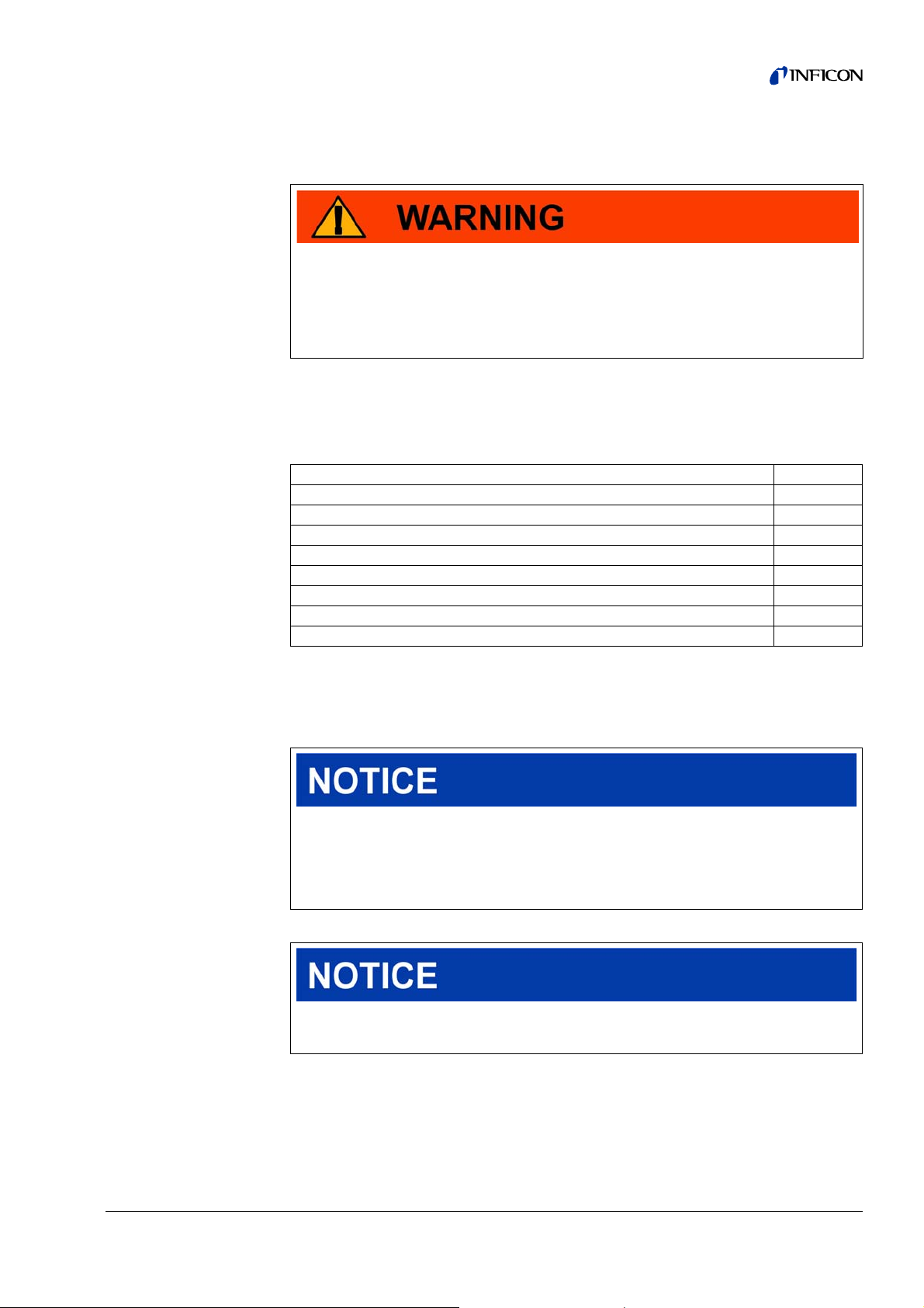
4.1 Construction of the unit
Fig: 1 Mass spectrometer module LDS3000
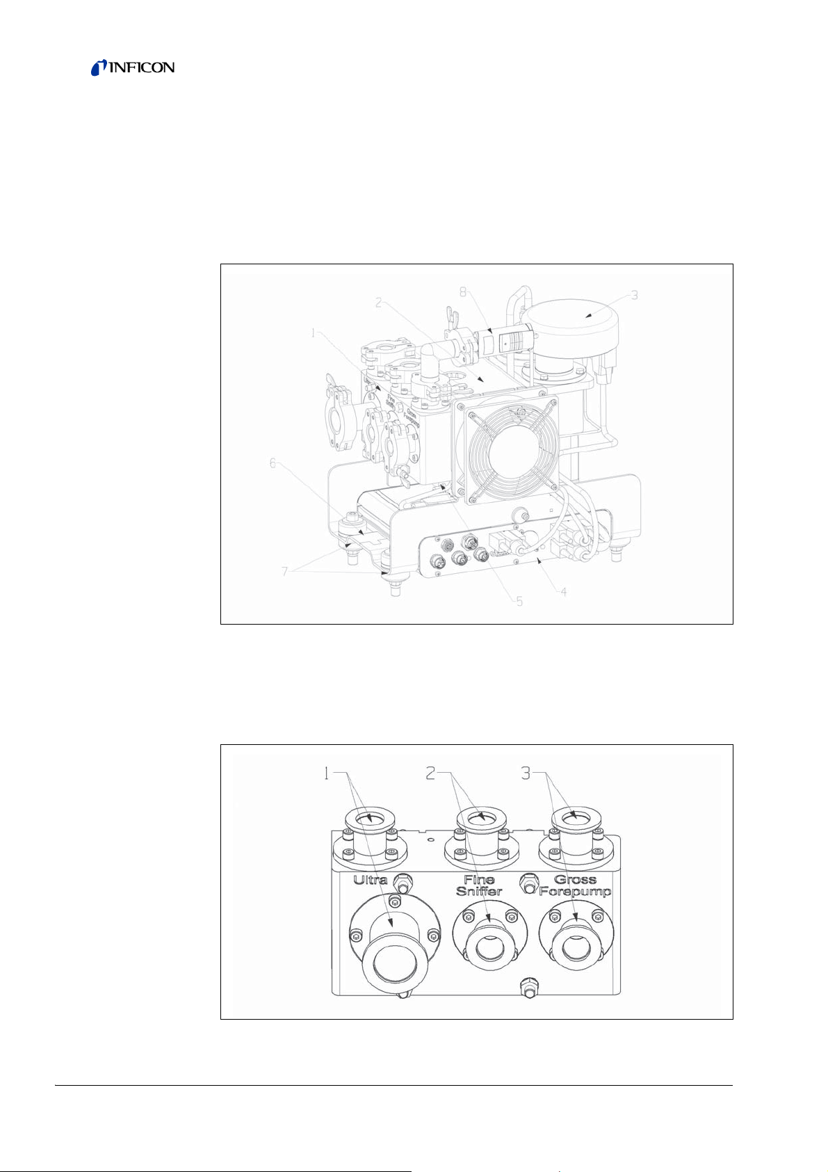
1 - Terminal block
Connections for test system, backing pump, PIRANI gauge, internal calibration leak
and sniffer line.
1: Connection U
Fig: 2 Connection block
LTRA, 2: Connection FINE/SNIFFER, 3: Connection GROSS/FOREPUMP
10 Description
Page 11
2- Turbo molecular pump
Turbo molecular pump with cooling unit
3 - Pre-amplifier
Pre-amplifier of the mass spectrometer module
4 - MSB box
Interfaces of the mass spectrometer module (see Chapter 4.1.1, page 11)
5 - Inverter turbo molecular pump
Electronic controller of the turbo molecular pump
6 - Rating plate
Rating plate containing mass spectrometer module specifications
7 - Fasteners
Fasteners for installing the mass spectrometer module in a test system
8 - PIRANI pressure measurement location
PIRANI gauge for measuring the pressure of the backing pump
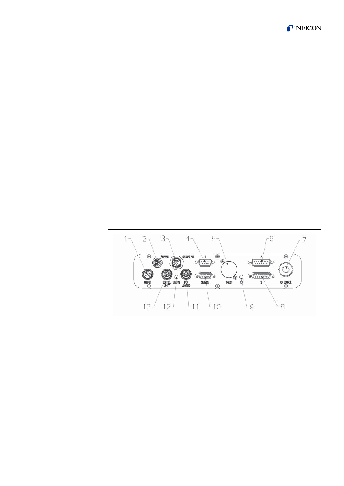
4.1.1 MSB box
Fig: 3 MSB box connections
1 - OUTPUT
Connection for gas ballast and three valves (not used, reserve)
Connection plug arrangement
1 Valve 2 (gas ballast), 24 V, max. 1 A
2 Valve 3 (not used)
3 Valve 4 (not used)
4 Valve 6 (not used)
5GND
2 - SNIFFER
Electrical connection for the sniffer line
Description 11
Page 12

3 - GAUGES, EXT
Connection for optional external pressure measurement locations (0 ... 10 V or
0 … 20 mA) for INFICON Service
Connection plug arrangement
1 +24 V output, max. 200 mA
2 Input for P3 service gauge, 0 ... 10 V
3GND
4 Reference to input for P3 service gauge
5 20 mA input for P3 service gauge
4 - 1
Connection for PIRANI gauge, test leak and suppressor on the pre-amplifier (premounted, three-core cable)
5 - 24VDC
Connection for 24 V power supply pack used to supply mass spectrometer module,
control unit, I/O module and bus module.
6 - 2
Connection for inverter turbo molecular pump and fan turbo molecular pump (premounted, two-core cable)
7 - ION SOURCE
Connection for ion source
8 - 3
Connection for pre-amplifier
9 -
Power LED
The Power LED and Status LED indicate the status of the unit; see no. 12 - S
10 - SERVICE
RS232 connection for INFICON Service
11 - I/O / ANYBUS
Connection for I/O or bus module or control unit
Information The connections I/O / A
NYBUS and CONTROL UNIT have the same
functions. You have the choice of connecting:
– Control unit CU1000 + I/O module IO1000 or
– Control unit CU1000 + bus module BM1000 or
– I/O module IO1000 + bus module BM1000 or
– 2 control units CU1000 or
– 2 I/O modules IO1000 (configurable only together)
TATUS.
12 Description
Page 13
12 - STATUS
Status LED
The Power LED and Status LED indicate the status of the unit.
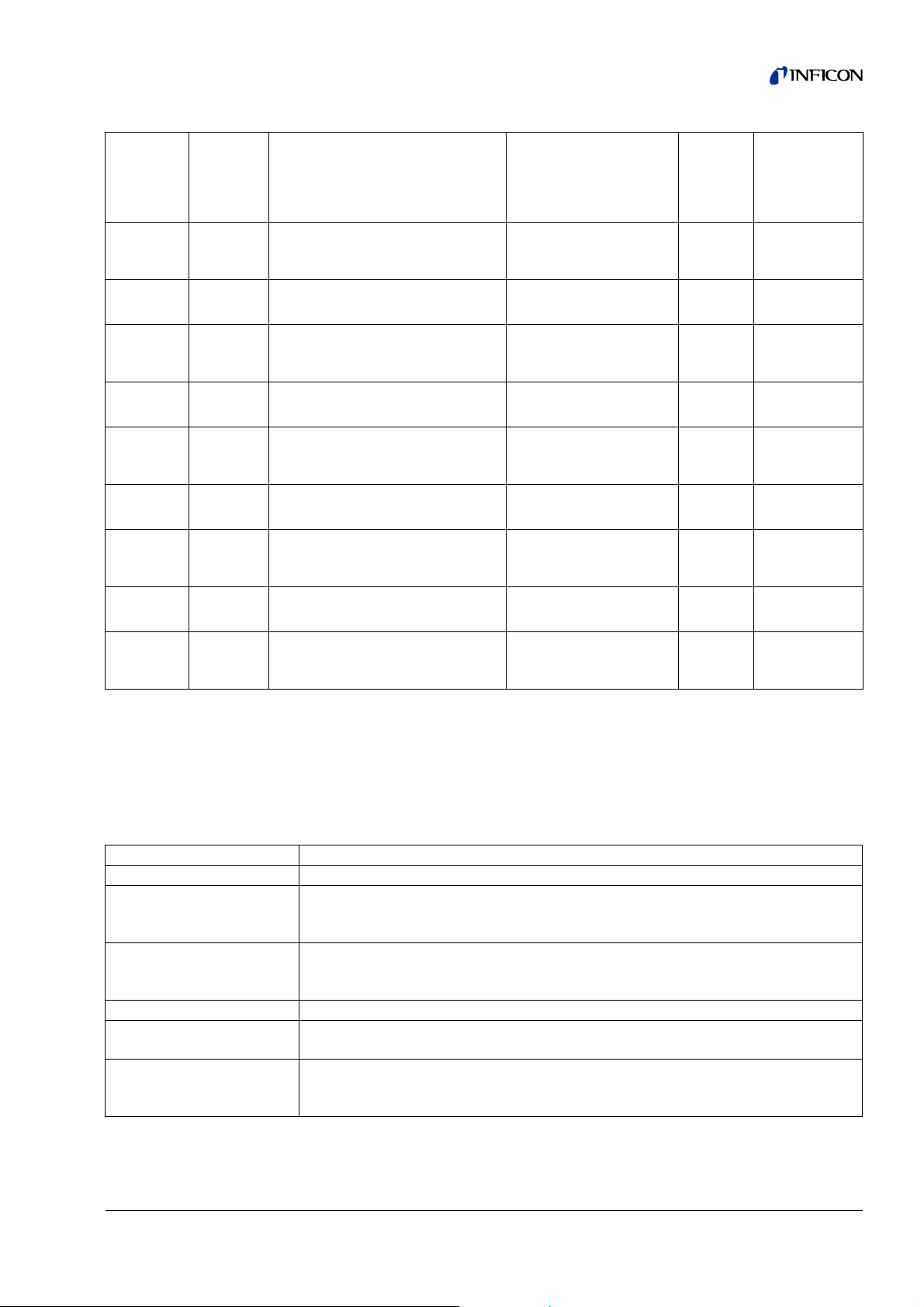
Power LED Status LED Meaning
Off Red Device not ready for operation
Green Blue Turbo molecular pump is starting
Green Orange Emission is switched on
Green Green Emission is stable
Green Violet
Green
Green, flashes slowly Supply voltage < 21.6 V
Green, flashes fast Supply voltage > 26.4 V
Green, flashes fast Off Software is being updated
Green Green, flashes fast Software is being updated
13 - CONTROL UNIT
Connection for control unit or I/O or bus module
Information The connections C
functions. You have the choice of connecting:
– Control unit CU1000 + I/O module IO1000 or
– Control unit CU1000 + bus module BM1000 or
– I/O module IO1000 + bus module BM1000 or
– 2 control units CU1000 or
– 2 I/O modules IO1000 (configurable only together)
Error codes of the
status LED
ONTROL UNIT and I/O / ANYBUS have the same
Speed of the turbo molecular pump is
not within the normal range
Different activities of the unit
4.2 Function
The mass spectrometer module is a detection device for the test gases helium and
hydrogen. Integrated in test systems, the unit is used to detect gas being emitted
from a test object in order to indicate leaks.
The unit can be used both as a vacuum leak detector and a sniffer leak detector.
The MSB box outputs data on digital interfaces to the control unit CU1000, I/O
module IO1000 or bus module BM1000.
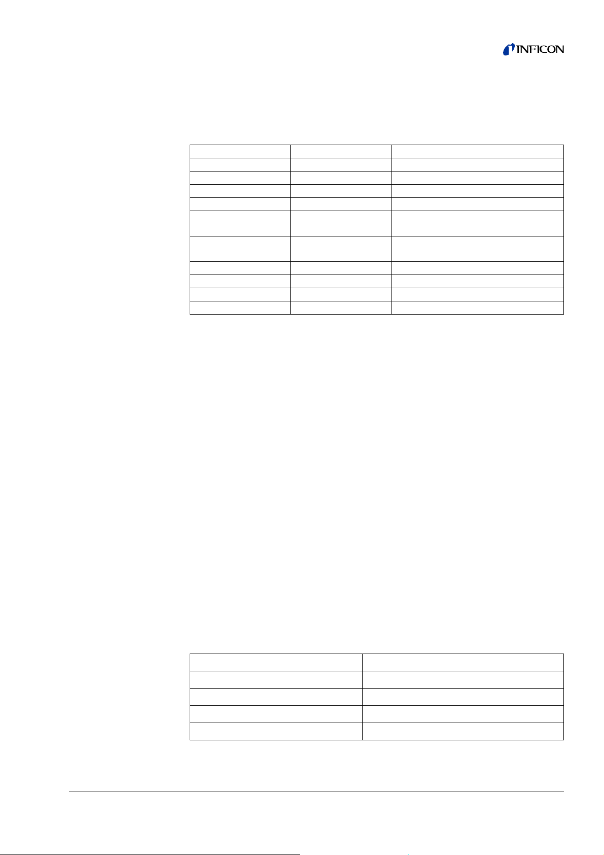
4.3 Technical data
4.3.1 Mechanical data
Dimensions (W x H x D) 320 mm x 280 mm x 240 mm
Weight 14.3 kg
Connection G
Connection F
Connection U
ROSS/FOREPUMP 2xDN16
INE/SNIFFER 2xDN16
LTRA DN 16 and DN 25
Description 13
Page 14
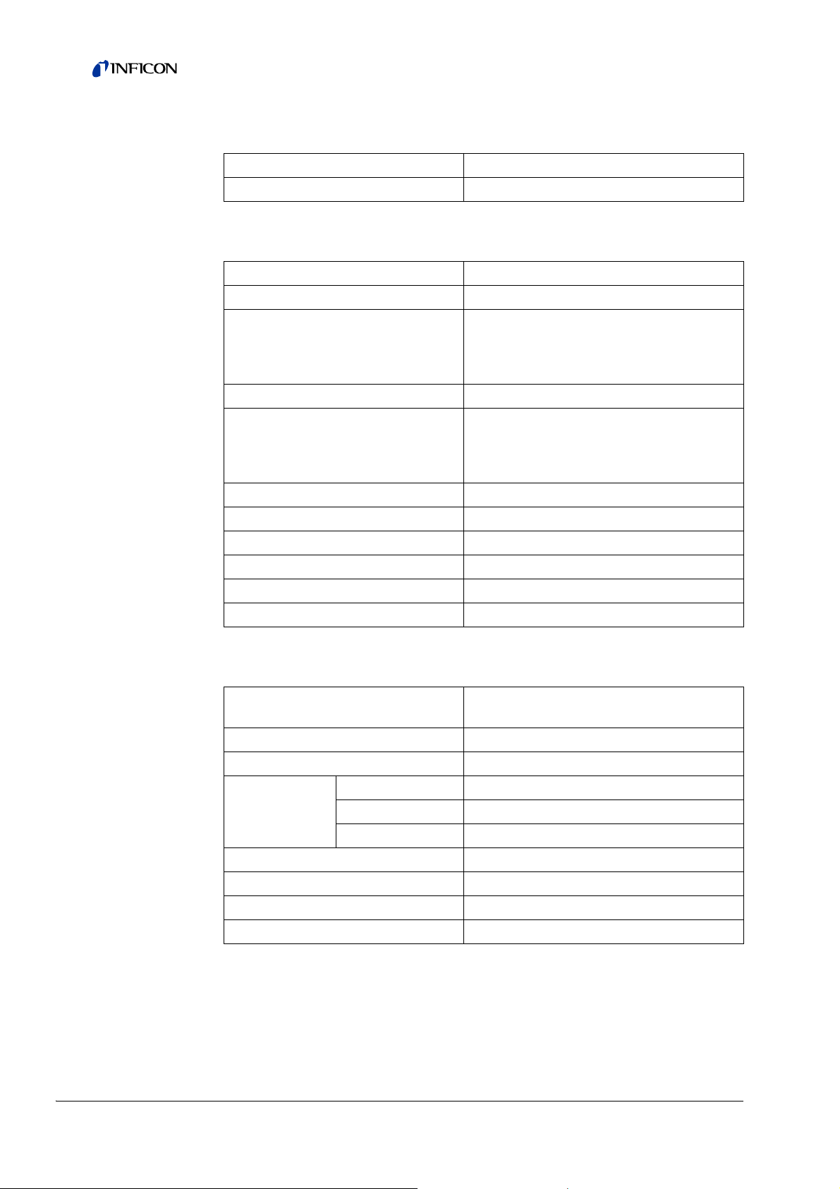
4.3.2 Electrical data
Supply voltage 24 V ± 10% DC
Power input max. 10 A
4.3.3 Physical data
Noise level < 60 dB(A)
Detectable gases
Max. inlet pressure
(varying with the operation mode and
the speed of the turbo molecular
pump)
Operation in vacuum mode
Minimum detectable leak rate
(varying with the operation mode and
the speed of the turbo molecular
pump):
Time until ready for operation 150 s
Operation in Sniffer mode
4
He, H2, Mass 3 (e. g. H-D, 3He or H3)
0.2 mbar ... 18 mbar
Helium < 5 x 10
-12
mbar·l/s
Minimum detectable leak rate:
Helium < 1 x 10
Response time in Sniffer mode G
4.3.4 Ambient conditions
Permissible ambient temperature
(during operation)
Permissible storage temperature -20 °C ... 60 °C
Max. relative humidity
at temperatures:
Type of protection IP 40
Pollution degree II
Max. altitude above sea level 2000 m
Max. induction 7 mT
-7
mbar·l/s
ROSS: < 5 s, FINE/ULTRA: < 1 s
10 °C ... 45 °C
< +31 °C 80%
+31 °C to +40 °C decreasing linearly from 80% ... 50%
> +40 °C 50%
14 Description
Page 15
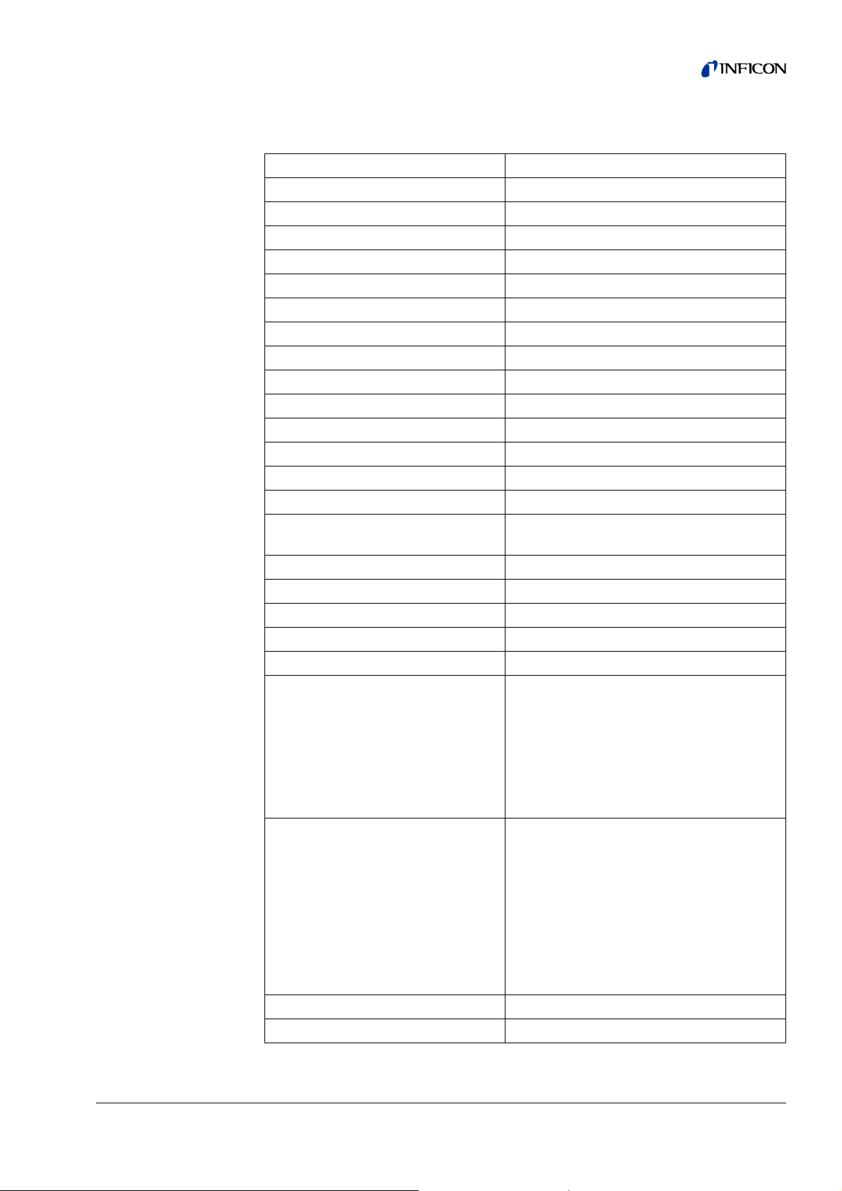
4.3.5 Factory settings
Parameter Factory setting
Operation mode Vacuum
Bus module address 126
Pressure capillary surveillance (min.) 0.4 mbar
Pressure capillary surveillance (max.) 2 mbar
Pressure unit mbar
Emission On
Upper limit exponent 1 x 10
Filter leak rate threshold 1 x 10
Filter zero time 5 s
Filter mode I•CAL
Gas ballast Off
I/O module protocol ASCII
Calibration request Off
Calibr. factor xxx Mx 1
-5
-10
Calibration factor VAC/SNIF Mx
1.0
(for vacuum, sniffer and all masses)
Cathode selection Auto Cat1
Compatibility mode LDS3000
Config. Analog output 1 Leak rate mantissa
Config. Analog output 2 Leak rate exponent
Config. Analog output scale 0.5 V / decade
Pin 1: Trigger 1, inverted
Pin 2: Trigger 2, inverted
Pin 3: Trigger 3, inverted
Configuration dig. outputs
Pin 4: Trigger 4, inverted
Pin 5: Ready
Pin 6: Error, inverted
Pin 7: CAL request, inverted
Pin 8: Open, inverted
Pin 1: Select dyn. / normal CAL
Pin 2: Sniff
Pin 3: Start/Stop, inverted
Pin 4: Zero
Configuration dig. Inputs
Pin 5: External CAL
Pin 6: Internal CAL
Pin 7: Clear
Pin 8: Pin 9: Pin 10: -
Leak rate unit SNIFF mbar*l/s
Leak rate unit VAC mbar*l/s
Description 15
Page 16
Parameter Factory setting
Fan mode Fan always on
Machine factor in standby Off
Machine factor / Sniff factor 1.0 (for all masses)
Mass 4
Maximum pressure VAC 18 mbar
Module at I/O connector IO1000
Nominal state TMP On
Test leak external SNIF 9.9 x 10
Test leak external VAC 9.9 x 10
Test leak internal 9.9 x 10
-2
-2
-2
Sniff factor 1.0 (for all masses)
TMP speed 1500
Trigger 1/2/3/4 level 1 x 10
-5
mbar·l/s
MOff
Zero with Start Off
Zero mode Normal
Zero key sniffer On
16 Description
Page 17
5 Installation
5.1 Rotating the MSB box
If required, you can push the MSB box into the mass spectrometer module LDS3000
on the rear side.
► Remove lock of the MSB box.
► Screw lock into the threads on the rear side of the MSB box.
► Disconnect all cables from the MSB box.
► Disconnect all cable clips from the frame.
► Pull out the MSB box.
► Push MSB box on the rear side and turned (with plug markings upside down) into
the mass spectrometer module LDS3000.
► Connect all cables to the MSB box.
► Fasten all cable clips on the frame.
► Close the lock.
The mass spectrometer module LDS3000 is ready for operation.
5.2 Installing the mass spectrometer module on the test system
Information The mass spectrometer module can be mounted in any position.
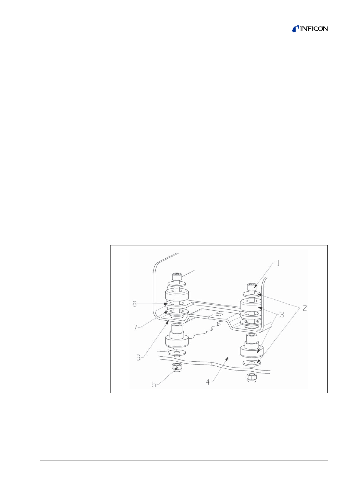
Fig: 4 Components of a fastener
1 Mounting screw M8 x 50
2Washer
3 MO bearing
4 Test system
5 Nut M8 (self-locking)
6 Base frame
7 Rubber spacer
8 MSB box guide
Installation 17
Page 18
Self-locking nuts M8
Open-end wrench, size 13
Allen wrench, size 6
Holes for installation inside the test system
The mass spectrometer module is delivered with fastening screws and transport nuts
already mounted.
1 Remove transport nuts.
2 Drill through-holes:
– X distance: 283 mm
– Y distance: 121.5 mm
– Through-hole in sheet metal: 9 mm
– Mounting screws: M8 x 50
Material damage if washers are missing
Failure to install the washers can cause the MO bearings to pull out.
► Always install washers between test system and MO bearings.
3 Use self-locking nuts (but NO transport nuts) to install the mass spectrometer
module.
Severe injuries due to mass spectrometer module breaking out
If not screwed down properly, the mass spectrometer module can be caused to
break out if the rotor of the turbo molecular pump suddenly locks up. This can result
in injuries of the most severe kind.
► Mount the mass spectrometer module so that it cannot break out.
4 Place the mass spectrometer module on top of the through-holes and screw it
down using the fasteners.
18 Installation
Page 19

5.3 Connecting the mass spectrometer module to the test system
The operation mode of the vacuum connection and the speed of the turbo molecular
pump define:
• Minimum detectable leak rate (MDLR)
• Maximum inlet pressure (P
• Volume flow rate (S)
max
)
Connection
Speed turbo molecular pump
1000 Hz 1500 Hz
-12
mbar·l/s < 1 x 10
U
LTRA
MDLR: < 5 x 10
P
: 0.2 mbar 0.2 mbar *
max
S: 5l/s 6l/s
MDLR: < 1 x 10
INE
F
P
: 0.9 mbar 0.4 mbar *
max
-11
mbar·l/s < 5 x 10
S: 1.8 l/s 2.5 l/s
MDLR: < 1 x 10⁻⁹mbar·l/s < 2 x 10⁻⁸mbar·l/s
G
ROSS
P
: 18 mbar 15 mbar
max
S: depends on the backing pump
* constantly permissible inlet pressure
Temporary exceed (< 3 s):
Permissible inlet pressure is 0.4 mbar in U
LTRA and 0.7 mbar in FINE.
Long-term exceed (> 3 s):
Warning (TMP overheating) and possible damage to the filament.
-11
-11
mbar·l/s
mbar·l/s
Material damage due to pressure surges
Pressure surges exceeding the maximum inlet pressure will damage the mass
spectrometer module.
► Do not exceed the maximum inlet pressure.
1 Set the operation mode vacuum connection and the speed turbo molecular pump
in accordance with the physical vacuum conditions found in the test system.
2 Connect the mass spectrometer module to the U
LTRA, FINE or GROSS connections
on the vacuum system of the test system.
3 Set the speed of the turbo molecular pump.
Installation 19
Page 20
5.4 Connection of the connection block
1 Connect PIRANI gauge and backing pump to GROSS/FOREPUMP.
2 Connect the test leak to the second available flange of the vacuum connection.
For the unit to operate correctly upon opening of the sniffer valve, no additional line
can be connected between the connection block and the sniffer valve or between the
sniffer valve and the sniffer line.
3 Connect the sniffer line to F
INE.
5.5 Connecting the MSB box
Information The connections are close together. To make installation easier, first
connect the inner connections, then the outer ones.
Material damage if power supply pack has the wrong specifications or is
connected improperly
A power supply pack that has the wrong specifications or is connected improperly
can destroy the unit.
► Use a suitable power supply pack:
– Use a power supply pack that supplies an output voltage with electrically
protective separation
– Output voltage: 24 V +/-10%
– Current rating: min. 8 A
► If the short-circuit current of the power supply pack is > 10 A, connect a fuse
between power supply pack and mass spectrometer module.
► Use a power cable with a large enough cross section.
1 Connect the 24 V power cable to the included plug (connections: +24 V to 1+ and
GND to 1-).
2 Plug in the mounted plug of the 24V power supply cable in 24VDC.
3 Use the data cable to connect the control unit to C
4 Use the data cable to connect the I/O or bus module to I/O as needed.
5 Connect the PIRANI gauge and the test leak to the cable of socket 1.
6 Connect the sniffer line to S
7 Connect the gas ballast valve to O
NIFFER as needed.
UTPUT as needed.
ONTROL UNIT as needed.
20 Installation
Page 21
6 Operation
You can use the following accessories in combination with the mass spectrometer
module:
• CU1000 (control unit)
• BM1000 (bus module)
• IO1000 (I/O module)
The following applies to the functions and settings described in this chapter:
Accessories Information on Are described in
Control unit Menu Operating Manual Control Unit CU1000
Bus module Commands Interface Protocols LDS3000
I/O module
Commands Interface Protocols LDS3000
Digital input and
outputs, Analog
outputs
Danger to life and material damage due to unsuitable operating conditions
There is danger to life due to unsuitable operating conditions. The unit can become
damaged.
Installation manual I/O module IO1000
► Avoid changing the position of the unit in an abrupt manner.
► Avoid extreme external vibrations and impact.
6.1 Switching the unit on
1 Switch on the backing pump.
2 Establish the power supply to the mass spectrometer module.
System starts up automatically.
6.2 Assigning the analog outputs of the I/O module
The analog outputs of the I/O module IO1000 can be assigned different
measurement displays via the control unit CU1000 or the I/O module IO1000.
► Assign the analog outputs of the I/O module as needed:
S
ETTINGS > SET UP > INTERFACES > I/O MODULE > ANALOG OUTP. >
C
ONFIG. ANALOG OUTPUTS 1/2
Operation 21
Page 22

6.2.1 Factory layout
Analog output 1: Leak rate mantissa
Analog output 2: Leak rate exponent
6.2.2 Possible layouts
Off
The analog outputs are disabled (output voltage = 0 V).
Pressure p1 / Pressure p2
1 ... 10 V; 0.5 V / decade; 1 V = 1 x 10
Leak rate mantissa
1 ... 10 V; linear; in used unit
Information Useful only if the other analog output is assigned “Leak rate exponent”.
Leak rate exponent
1 ... 10 V; 0.5 V / decade; step function; 1 V = 1 x 10
Information Useful only if the other analog output is assigned “Leak rate mantissa”
or “Leak rate ma. hys.”.
-3
mbar
-12
; in used unit
Leak rate linear
x ... 10 V; linear; in used unit
The upper limit (= 10 V) is set via the parameter “Upper limit exponent”.
Leak rate log.
x ... 10 V; logarithmic; in used unit
The upper limit (= 10 V) and the scale (V / decades) are set via the parameters
“Upper limit exponent” and “Scale for leak rate”.
For example:
Upper limit set to 10
Scale set to 5 V / decade.
Lower limit is 10
-5
mbar·l/s (= 10 V).
-3
mbar·l/s (= 0 V).
22 Operation
Page 23

Via interface
The output voltage can be specified via the LD protocol command 221.
Leakage rate Ma. Hys.
0.7 ... 10 V; linear; in used unit
Information Useful only if the other analog output is assigned “Leak rate exponent”.
This layout prevents the exponent from constantly jumping between two decades.
0.7 V corresponds to a leakage rate of 0.7 x 10
9.9 V corresponds to a leakage rate of 9.9 x 10
Pressure p1 (1 V / dec.) / Pressure p2 (1 V / dec.)
1 ... 10 V; 1 V / decade; 2.5 V = 1 x 10
Leak rate log. H. / Leak rate exp. Inv.
This assignment ensures backward compatibility to older units.
6.2.3 Output voltages in case of error
The following voltages will be applied at the analog outputs in the event of an error:
Compatibility mode Voltage
LDS1000 0 V
LDS2010 10 V
LDS3000 10.237 V
-x
.
-x
.
-3
mbar; 8.5 V = 1000 mbar
Operation 23
Page 24

6.2.4 Configuration (LDS2010-compatible)
LDS2010
setting in
menu item
22
1 1
1 2
21
22
3 1
3 2
41
42
5 1
5 2
61
62
8 1
8 2
Analog
output
LDS2010 function LDS3000 function
Leak rate mantissa in used unit
1...10V
Leak rate exponent (step function)
in used unit
1 ... 10 V, 0.5 V/decade,
1V=1E-12
Leak rate log. in used unit
1 ... 10 V, 0.5 V/decade,
1V=1E-12
Pressure p1 log. in used unit
1 ... 10 V, 0.5 V/decade,
1V=1E-3mbar
Leak rate mantissa in mbar·l/s
1...10V
Leak rate exponent (step function)
in mbar·l/s
1 ... 10 V, -1 V/decade,
0 V = 1E0 mbar·l/s
Leak rate log.
0 ... 10 V, 1 V/decade,
0 V = 1E-10 mbar·l/s
Pressure p1 log. in mbar
1 V/decade, 2.5 ... 8.5 V,
2.5V=1E-3mbar,
5.5 V = 1E0 mbar
Leak rate mantissa in used unit
1 ... 10 V rise, 0.7 ... 10 V fall
Leak rate exponent in used unit
1 ... 10 V, 0.5 V/decade,
0V=1E-14
Leak rate log. in Pa·m³/s
0 10 V, 1 V/decade,
0 V = 1E-12 Pa·m³/s =
1E-12 mbar·l/s
Pressure p1 log. in Pa
1 V/decade, 2.5 ... 8.5 V,
2.5V=1E-3mbar
Leak rate log. in Pa·m³/s
0 ... 10 V, 1 V/decade,
0 V = 1E-12 Pa·m
1E-12 mbar·l/s
Pressure p2 log. in Pa
1 V/decade, 2.5 ... 8.5 V,
2.5V=1E-3mbar
3
/s =
Leak rate mantissa irrelevant irrelevant
Leak rate exponent irrelevant irrelevant
Leak rate log. 0.5 V/dec. 1E6 [used unit]
Pressure p1 irrelevant irrelevant
Leak rate mantissa irrelevant irrelevant
LR exponent inverted irrelevant irrelevant
Leak rate log. 1 V/dec. 1.00E+00
p1 1 V/dec. irrelevant irrelevant
LR mantissa hyst. irrelevant irrelevant
Leak rate exponent irrelevant irrelevant
Leak rate log. 1 V/dec. 1E-2 mbar·l/s
p1 1 V/dec. irrelevant irrelevant
Leak rate log. 1 V/dec. 1E-2 mbar·l/s
p2 1 V/dec. irrelevant irrelevant
Decade
scale
Upper limit
value
(10 V = ...)
24 Operation
Page 25

LDS2010
setting in
menu item
Analog
output
22
91
92
10 1
10 2
11 1
11 2
12 1
12 2
13 1
13 2
14 1
14 2
15 1
15 2
16 1
16 2
LDS2010 function LDS3000 function
Pressure p1 log. in Pa
1 V/decade, 2.5 ... 8.5 V,
p1 1 V/dec. irrelevant irrelevant
2.5 V = 1E-3 mbar
Pressure p2 log. in Pa
1 V/decade, 2.5 ... 8.5 V,
p2 1 V/dec. irrelevant irrelevant
2.5 V = 1E-3 mbar
Leak rate log. in mbar·l/s
0...8V, 2V/decade,
Leak rate log. 2V/dec. 1E+2 mbar·l/s
0V=1E-3mbar·l/s
Leak rate log. in mbar·l/s
0 ... 10 V, 3 V/decade,
Leak rate log. Special_1 1E+1 mbar·l/s
0V=1E-3mbar·l/s
Leak rate log. in mbar·l/s
0...8V, 2V/decade,
Leak rate log. 2 V/dec. 1E+1 mbar·l/s
0V=1E-4mbar·l/s
Leak rate log. in mbar·l/s
0 ... 10 V, 3 V/decade,
Leak rate log. Special_1 1E+0 mbar·l/s
0 V = 1E-4 mbar·l/s
Leak rate log. in mbar·l/s
0...8V, 2V/decade,
Leak rate log. 2V/dec. 1E0 mbar·l/s
0V=1E-5mbar·l/s
Leak rate log. in mbar·l/s
0 ... 10 V, 3 V/decade,
Leak rate log. Special_1 1E-1 mbar·l/s
0V=1E-5mbar·l/s
Leak rate log. in mbar·l/s
0...8V, 2V/decade,
Leak rate log. 2 V/dec. 1E-1 mbar·l/s
0V=1E-6mbar·l/s
Leak rate log. in mbar·l/s
0 ... 10 V, 3 V/decade,
Leak rate log. Special_1 1E-2 mbar·l/s
0V=1E-6mbar·l/s
Leak rate log. in mbar·l/s
0...8V, 2V/decade,
Leak rate log. 2V/dec. 1E-2 mbar·l/s
0V=1E-7mbar·l/s
Leak rate log. in mbar·l/s
0 ... 10 V, 3 V/decade,
Leak rate log. Special_1 1E-3 mbar·l/s
0V=1E-7mbar·l/s
Leak rate log. in mbar·l/s
0...8V, 2V/decade,
Leak rate log. 2 V/dec. 1E-3 mbar·l/s
0V=1E-8mbar·l/s
Leak rate log. in mbar·l/s
0 ... 10 V, 3 V/decade,
Leak rate log. Special_1 1E-4 mbar·l/s
0V=1E-8mbar·l/s
Leak rate log. in mbar·l/s
0...8V, 2V/decade,
Leak rate log. 2V/dec. 1E-4 mbar·l/s
0V=1E-9mbar·l/s
Leak rate log. in mbar·l/s
0 ... 10 V, 3 V/decade,
Leak rate log. Special_1 1E-5 mbar·l/s
0V=1E-9mbar·l/s
Decade
scale
Upper limit
value
(10 V = ...)
Operation 25
Page 26

LDS2010
setting in
menu item
22
17 1
17 2
18 1
18 2
20 1
20 2
21 1
21 2
22 1
22 2
23 1
23 2
24 1
24 2
25 1
25 2
26 1
Analog
output
LDS2010 function LDS3000 function
Leak rate log. in mbar·l/s
0...8V, 2V/decade,
0 V = 1E-10 mbar·l/s
Leak rate log. in mbar·l/s
0 ... 10 V, 3 V/decade,
0 V = 1E-10 mbar·l/s
Leak rate log. in mbar·l/s
0...8V, 2V/decade,
0 V = 1E-11 mbar·l/s
Leak rate log. in mbar·l/s
0 ... 10 V, 3 V/decade,
0 V = 1E-11 mbar·l/s
Leak rate lin. in mbar·l/s
0...10V, 1V=1mbar·l/s
Leak rate log. in mbar·l/s
0...4V, 1V/decade,
0V=1E-3mbar·l/s
Leak rate lin. in mbar·l/s
0...10V, 1V=1E-1mbar·l/s
Leak rate log. in mbar·l/s
0...4V, 1V/decade,
0V=1E-4mbar·l/s
Leak rate lin. in mbar·l/s
0...10V, 1V=1E-2mbar·l/s
Leak rate log. in mbar·l/s
0...4V, 1V/decade,
0 V = 1E-5 mbar·l/s
Leak rate lin. in mbar·l/s
0...10V, 1V=1E-3mbar·l/s
Leak rate log. in mbar·l/s
0...4V, 1V/decade,
0V=1E-6mbar·l/s
Leak rate lin. in mbar·l/s
0...10V, 1V=1E-4mbar·l/s
Leak rate log. in mbar·l/s
0...4V, 1V/decade,
0V=1E-7mbar·l/s
Leak rate lin. in mbar·l/s
0...10V, 1V=1E-5mbar·l/s
Leak rate log. in mbar·l/s
0...4V, 1V/decade,
0V=1E-8mbar·l/s
Leak rate lin. in mbar·l/s
0...10V, 1V=1E-6mbar·l/s
Leak rate log. 2 V/dec. 1E-5 mbar·l/s
Leak rate log. Special_1 1E-6 mbar·l/s
Leak rate log. 2 V/dec. 1E-6 mbar·l/s
Leak rate log. Special_1 1E-7 mbar·l/s
Leak rate linear irrelevant 1E1 mbar·l/s
Leak rate log. 1 V/dec. 1E7 mbar·l/s
Leak rate linear irrelevant 1E0 mbar·l/s
Leak rate log. 1 V/dec. 1E6 mbar·l/s
Leak rate linear irrelevant 1E-1 mbar·l/s
Leak rate log. 1 V/dec. 1E5 mbar·l/s
Leak rate linear irrelevant 1E-2 mbar·l/s
Leak rate log. 1 V/dec. 1E4 mbar·l/s
Leak rate linear irrelevant 1E-3 mbar·l/s
Leak rate log. 1 V/dec. 1E3 mbar·l/s
Leak rate linear irrelevant 1E-4 mbar·l/s
Leak rate log. 1 V/dec. 1E2 mbar·l/s
Leak rate linear irrelevant 1E-5 mbar·l/s
Decade
scale
Upper limit
value
(10 V = ...)
26 Operation
Page 27
LDS2010
setting in
menu item
22
26 2
27 1
27 2
28 1
28 2
29 1
29 2
30 1
30 2
Analog
output
LDS2010 function LDS3000 function
Leak rate log. in mbar·l/s
0...4V, 1V/decade,
0V=1E-9mbar·l/s
Leak rate lin. in mbar·l/s
0...10V, 1V=1E-7mbar·l/s
Leak rate log. in mbar·l/s
0...4V, 1V/decade,
0 V = 1E-10 mbar·l/s
Leak rate lin. in mbar·l/s
0...10V, 1V=1E-8mbar·l/s
Leak rate log. in mbar·l/s
0...4V, 1V/decade,
0 V = 1E-11 mbar·l/s
Leak rate lin. in mbar·l/s
0...10V, 1V=1E-9mbar·l/s
Leak rate log. in mbar·l/s
0...4V, 1V/decade,
0 V = 1E-11 mbar·l/s
Leak rate lin. in mbar·l/s
0 ... 10 V, 1 V = 1E-10 mbar·l/s
Leak rate log. in mbar·l/s
0...4V, 1V/decade,
0 V = 1E-11 mbar·l/s
Leak rate log. 1 V/dec. 1E1 mbar·l/s
Leak rate linear irrelevant 1E-6 mbar·l/s
Leak rate log. 1V/dec. 1E0 mbar·l/s
Leak rate linear irrelevant 1E-7 mbar·l/s
Leak rate log. 1 V/dec. 1E-1 mbar·l/s
Leak rate linear irrelevant 1E-8 mbar·l/s
Leak rate log. 1V/dec. 1E-2 mbar·l/s
Leak rate linear irrelevant 1E-9 mbar·l/s
Leak rate log. 1 V/dec. 1E-3 mbar·l/s
Decade
scale
Upper limit
value
(10 V = ...)
6.3 Assigning the digital inputs of the I/O module
The available functions can be assigned in any way necessary to the digital inputs
PLC-IN 1 ... 10 of the I/O module.
Active signal: typically 24 V; inactive signal: typically 0 V.
The 24V output of the I/O module can be used as an active signal.
Function Flank/state: Description
NO_FUNCTION - no function
inactive→ active:
DYN_CAL
CAL_EXTERN
CAL_INTERN inactive→ active: Start internal calibration.
SNIFF/VAC
START
active→ inactive:
inactive→ active:
active→ inactive:
inactive→ active:
active→ inactive:
inactive→ active: Switch to Meas.
Start external dynamic calibration.
Apply value for background and finish calibration.
Start external calibration.
Apply value for background and finish calibration.
Enable sniffer mode.
Enable vacuum mode.
(Z
ERO is possible, all trigger outputs switch depending on the
leakage rate.)
Operation 27
Page 28

Function Flank/state: Description
inactive→ active:
STOP
Switch to Standby.
ERO is not possible, all trigger outputs will return "Fail".)
(Z
ZERO
inactive→ active:
active→ inactive:
Switch Z
Switch Z
ERO on.
ERO off.
ZERO_PULS inactive→ active. Switch ZERO on or off.
CLEAR
GASBALLAST
inactive→ active:
inactive→ active:
active→ inactive:
Erase warning or error message / cancel calibration.
Open gas ballast valve.
Close gas ballast valve unless always open.
External calibration mode for the "CAL" function:
inactive→ active:
External dynamic calibration
(without auto tune, allowing for the measuring times and pump
SELECT_DYN_NORMAL
active→ inactive:
cycle times set via the digital inputs)
External normal calibration
(with auto tune, not considering the system-specific measuring
times and pump cycle times)
START_STOP
inactive→ active:
active→ inactive:
Switch to Meas.
(Z
ERO is possible, all trigger outputs switch depending on the
leakage rate.)
Switch to Standby.
(Z
ERO is not possible, all trigger outputs will return "Fail".)
KEY_1 active: User "Operator"
KEY_2 active: User "Supervisor"
KEY_3 active: User "Integrator"
CAL inactive→ active:
When set to Standby, the unit will start an internal calibration.
When set to Meas, the unit will start an external calibration.
Information Every function can be inverted.
► Assign the digital inputs of the I/O module as needed:
S
ETTINGS > SET UP > INTERFACES > I/O MODULE > PLC INPUTS >
C
ONFIGURATION DIG. INPUT
6.4 Assigning the digital outputs of the I/O module
The available functions can be assigned in any way necessary to the digital outputs
PLC-OUT 1 ... 8 of the I/O module:
Function State: Description
OPEN open: always open
TRIG1
TRIG2
TRIG3
TRIG4
READY
closed:
open:
closed:
open:
closed:
open:
closed:
open:
closed:
open:
Value exceeded leak rate threshold Trigger 1
Value fell below leak rate threshold Trigger 1
Value exceeded leak rate threshold Trigger 2
Value fell below leak rate threshold Trigger 2
Value exceeded leak rate threshold Trigger 3
Value fell below leak rate threshold Trigger 3
Value exceeded leak rate threshold Trigger 4
Value fell below leak rate threshold Trigger 4
Emission switched on, calibration process inactive, no error
Emission switched off, calibration process active or error
28 Operation
Page 29

Function State: Description
WARNING
ERROR
CAL_ACTIVE
closed:
open:
closed:
open:
closed:
open:
closed:
Warning
no warning
Error
no error
Unit is calibrated.
Unit is not calibrated.
and no external calibration: Calibration request
(e. g. in case of temperature change of 5 °C)
CAL_REQUEST
closed:
and external calibration: Request "Open external calibration
leak"
RUN_UP
ZERO_ACTIVE
EMISSION_ON
MEASURE
open:
closed:
open:
closed:
open:
closed:
open:
closed:
open:
no request
Running up
no run-up
Z
ERO switched on
Z
ERO switched off
Emission switched on
Emission switched off
Meas
(Z
ERO is possible, all trigger outputs switch depending on the
leakage rate.)
Standby or Emission disabled
(Z
ERO is not possible, all trigger outputs will return "Fail".)
STANDBY
SNIFF
closed:
open:
Standby
(Z
ERO is not possible, all trigger outputs will return "Fail".)
Meas
(Z
ERO is possible, all trigger outputs switch depending on the
leakage rate.)
closed:
open:
SNIFF
VAC
Information Every function can be inverted.
► Assign the digital outputs of the I/O module as needed:
S
ETTINGS > SET UP > INTERFACES > I/O MODULE > PLC OUTPUTS >
C
ONFIGURATION DIG. OUTPUT
Operation 29
Page 30

6.5 Starting/stopping the measurement
During the measurement During standby
Z
ERO is possible. ZERO is not possible.
The trigger outputs switch depending on
the leakage rate and the trigger threshold.
Sniff is possible. Sniff is not possible.
Calibration using PLC input or output will
start an external calibration.
Starting
Device in S
► Start measurement.
TANDBY
The output at the trigger outputs is:
Leakage rate value exceeded
threshold.
Calibration using PLC input and output
will start an internal calibration.
Device switched to M
Stopping
Unit measures
► Stop measurement.
Device switches to S
EASURE state.
TANDBY state.
6.6 Loading and storing parameters
You can use a USB stick to backup and restore the control unit and mass
spectrometer module parameters.
► Load parameters as needed:
F
UNCTIONS > DATA > PARAMETER > LOAD > LOAD PARAMETER
► Save parameters as needed:
F
UNCTIONS > DATA > PARAMETER > SAVE > SAVE PARAMETER
6.7 Select operation mode
VAC = Vacuum mode
S
NIFF = Sniff mode
► Select operation mode as needed:
S
ETTINGS > SET UP > OPERATION MODES > VAC/SNIFF > OPERATION MODE
30 Operation
Page 31

6.8 Activate/deactivate ZERO
ZERO can be used to suppress undesired helium backgrounds. If ZERO is enabled,
the currently measured leakage rate value will be interpreted as a helium background
and subtracted from all subsequently measured values.
The background value suppressed by Z
background changes inside the unit.
Information If the signal filter Fixed or 2-Zone is selected, then the background value
is automatically adjusted based on the configured zero time.
► Enable or disable Z
S
ETTINGS > ZERO/FILTER > ZERO > ZERO MODE
ZERO WITH START suppresses the helium background automatically when a
measurement is started.
► Enable or disable Z
S
ETTINGS > ZERO/FILTER > ZERO > ZERO WITH START
6.9 Selecting a signal filter
Signal filter
I•CAL
Fixed The leak rates are averaged at fixed intervals of 0.2 seconds.
2-Zone
► As a rule, use signal filter I•CAL.
► If the signal filter should simulate the time behavior of older units, then use filter
Fixed or 2-Zone.
► Select desired signal filter:
S
ETTINGS > ZERO/FILTER > FILTER > FILTER MODE
The leakage rates are averaged at time intervals that are optimized
for the range of the leakage rates.
Filter compatible with LDS1000 and LDS2000
The averaging period is switched depending on the leak rate
threshold.
ERO is adjusted automatically if the
ERO as needed:
ERO WITH START as needed:
Operation 31
Page 32
6.10 Calibrating the unit
► To ensure measuring accuracy, the unit must be calibrated regularly.
Information Recalibration at the start of every shift is recommended.
Incorrect measurement results due to premature calibration
If calibrated prematurely, the unit will produce incorrect measurement results.
► Allow the unit to run for at least 20 minutes before performing the calibration.
Calibration Particularities
internal
external
external dynamic
• with internal test leak • Auto tune (mass adjustment)
• Determining the calibration
factor with the signal of the test
leak tuned
• Determining the background
Following calibration, adjust
the machine/sniff factor as
needed, see Chapter 6.10.4,
page 34
• Vacuum mode: with external
test leak installed in the test
system
• Sniffer mode: with external
sniffer leak
• Taking the test system
characteristics into account
(pressure, split flow ratio)
• with external test leak installed
in the test system
• Taking the test system
characteristics into account
(pressure, split flow ratio,
measuring time)
• Measuring time based on the
dynamic signal curve
• Auto tune (mass adjustment)
• Determining the calibration
factor after tuning the signal of
the test leak
• Determining the background
• Determining the calibration
factor before tuning the signal
of the test leak
• Determining the background
32 Operation
Page 33

6.10.1 Internal calibration
Internal test leak connected.
1 Enter leakage rate of the test leak via digital interface (control unit CU1000,
I/O module IO1000 or bus module BM1000).
2 Start calibration.
Calibration is performed automatically.
6.10.2 External calibration
Vacuum mode: External test leak installed and open in or on the test system.
Sniffer mode: Sniffer line measures sniffer leak.
1 Enter leakage rate of the external test leak via digital interface (control
unit CU1000, I/O module IO1000 or bus module BM1000).
2 Wait until leakage rate signal is tuned and stable.
3 Start calibration.
Request C
4 Vacuum mode: Close test leak inside the test system.
5 Sniffer mode: Remove sniffer line from sniffer leak.
Leakage rate signal decreases.
6 Confirm measured background value is stable.
LOSE TEST LEAK
6.10.2.1 External dynamic calibration
Vacuum mode: External test leak installed and open in or on the test system.
Sniffer mode: Sniffer line measures sniffer leak.
1 Enter leakage rate of the external test leak via digital interface (control
unit CU1000, I/O module IO1000 or bus module BM1000).
2 Wait until leakage rate signal is tuned and stable.
3 If you wish to apply non-tuned leakage rate signal: Start calibration.
This leakage rate signal will be used for the calibration.
Request C
4 To determine the helium background, close the inlet valve on the test system.
Leakage rate signal decreases.
5 Confirm significantly decreased leakage rate signal.
LOSE TEST LEAK.
Operation 33
Page 34

6.10.3 Enable/disable Calibration request
If Calibration request is enabled, the unit will prompt the user to perform a calibration
30 minutes after it has been switched on and in case of temperature changes greater
than 5 °C.
► Enable or disable Calibration request as needed:
F
UNCTIONS > CAL > SETTINGS > CAL REQUEST > CALIBRATION REQUEST
6.10.4 Setting machine and sniff factor
The internal calibration will only calibrate the measurement system of a mass
spectrometer module that is uncoupled from the test system. If the unit is operated
in parallel to an additional pump system after an internal calibration (following the
split flow principle), the unit will indicate a leakage rate that is too low based on the
split flow ratio.
With the help of a corrective machine factor (in vacuum mode) and a sniff factor (in
sniffer mode), the unit indicates the actual leakage rate.
6.10.4.1 Setting machine and sniff factor manually
Mass spectrometer module calibrated internally.
1 Measure external test leak using the test system.
The unit indicates a leakage rate that is too low based on the split flow ratio.
2 Setting machine / sniff factor:
S
ETTINGS > SET UP > OPERATION MODES > VACUUM/SNIFFER > MACHINE FACTOR >
M
ASS 2/3/4 > MACHINE/SNIFF FACTOR M2/3/4
The unit indicates the actual leakage rate.
6.10.4.2 Setting machine and sniff factor using machine calibration
Internal test leak connected.
External test leak installed in or on the test system and closed.
1 Enter leakage rate of the internal and external test leak via digital interface
(control unit CU1000, I/O module IO1000 or bus module BM1000).
2 Start machine calibration.
Internal calibration is performed automatically.
Request O
3 Open external test leak and valve (if present) between the leak detector and the
system.
4 Confirm tuned and stable leakage rate signal.
Request C
5 Close external test leak.
6 Confirm tuned and stable leakage rate signal.
Machine/sniff factor is defined.
PEN TEST LEAK (External test leak).
LOSE TEST LEAK (External test leak).
34 Operation
Page 35

6.11 Select sample gas
The mass spectrometer module is capable of measuring the following gases:
• Hydrogen (H
• Mass 3 (H-D,
• Helium (
4
He)
)
2
3
He oder H3)
► Select desired mass:
S
ETTINGS > MASS > MASS
The machine, calibration and sniff factor are dependent on the configured mass and
are saved in the mass spectrometer module.
6.12 Decontaminating backing pump from test gas
The mass spectrometer module can control an electric 24V gas ballast valve of the
backing pump via the O
UTPUT connection.
► Controlling the gas ballast valve using digital outputs.
6.13 Selecting units for leakage rate
For control unit:
► Select desired unit of the leakage rate in vacuum mode:
V
IEW SETTINGS > UNITS (DISPLAY) > LEAK RATE UNIT VAC
► Select desired unit of the leakage rate in sniff mode:
V
IEW SETTINGS > UNITS (DISPLAY) > LEAK RATE UNIT SNIFF
For I/O or bus module:
► Select desired unit of the leakage rate in vacuum mode:
S
ETTINGS > SET UP > INTERFACES > UNITS (INTERFACE) > LEAK RATE UNIT VAC
► Select desired unit of the leakage rate in sniff mode:
S
ETTINGS > SET UP > INTERFACES > UNITS (INTERFACE) > LEAK RATE UNIT SNIFF
6.14 Selecting units for pressure
For control unit:
► Select desired unit for the pressure:
V
IEW SETTINGS > UNITS (DISPLAY) > PRESSURE UNIT
For I/O or bus module:
► Select desired unit for the pressure:
S
ETTINGS > SET UP > INTERFACES > UNITS (INTERFACE) > PRESSURE UNIT
Operation 35
Page 36

6.15 Enable/disable correction of the leakage rate in Standby
Enabled = machine/sniff factor is considered in Standby.
Disable = machine/sniff factor is not considered in Standby.
► Enable or disable correction of the leakage rate in Standby as needed:
S
ETTINGS > SET UP > OPERATION MODES > LR CORRECTION > MACHINE FACTOR IN
STANDBY
6.16 Setting the leakage rate threshold value
The mass spectrometer module has four independent leakage rate threshold values.
► Set the leakage rate threshold value as needed:
S
ETTINGS > TRIGGER > TRIGGER 1/2/3/4 > TRIGGER 1/2/3/4 LEVEL
6.17 Enable/disable ZERO key (Sniffer key)
► Enable or disable ZERO key on sniffer line as needed:
S
ETTINGS > SET UP > OPERATION MODES > SNIFFER > SNIFFER KEY > ZERO KEY
SNIFFER
6.18 Setting capillary surveillance
To detect clogged sniffer lines, the backing pressure is monitored in sniffer mode.
You can adjust the pressure threshold that will result in a warning if values fall below
it.
► Setting surveillance of the backing pressure:
S
ETTINGS > SET UP > OPERATION MODES > SNIFFER > CAPILLARY >
P
RESSURE CAPILLARY BLOCKED
6.19 Compatibility with LDS1000 and LDS2010
Switching the compatibility mode will cause the unit to load the corresponding factory
settings of the LDS1000, LDS2010 or LDS3000.
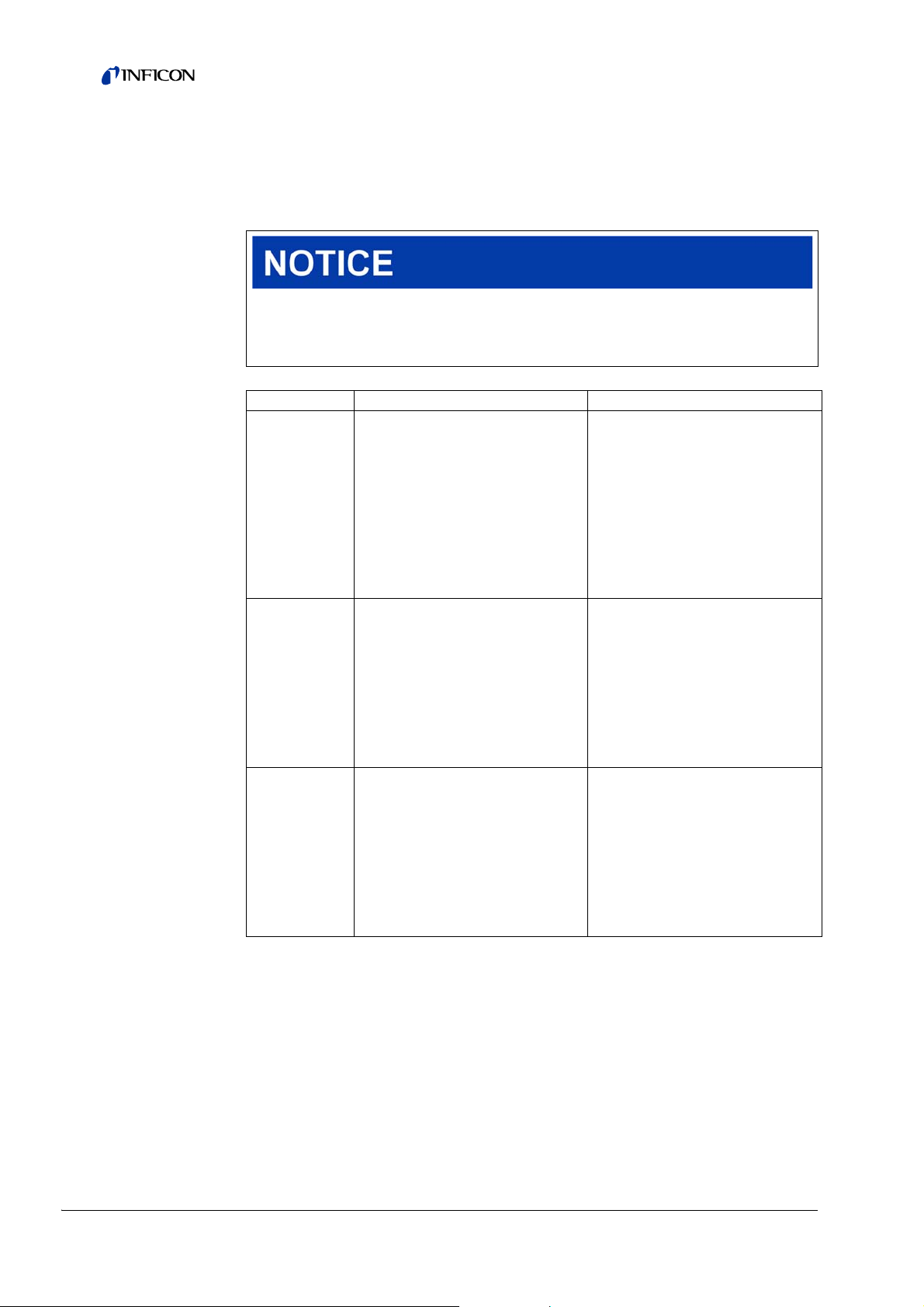
6.20 Warning and malfunction messages
Error
number
ASCII
protocol*
Limit
values
Error
number
102 W
104 W
106 W
Warning/
Error
Error
Error message
LDS3000
1xx system error (RAM, ROM, EEPROM, clock, ...)
Timeout EEPROM
MSB,
(number of parameter)
One EEPROM
parameter initialized,
(number of parameter)
EEPROM parameters
initialized,
(number of parameter)
number
LDS1000
protocol
84 43
84 43
84 43
Cause
EEPROM on IF board or
MSB defective
Following software update
or EEPROM defective
Following software update
or EEPROM defective
36 Operation
Page 37

Error
Error
number
Warning/
Error
Error message
LDS3000
number
LDS1000
protocol
110 W Clock is not set 16 16
122 W
125 W
127 W
No answer from bus
module
I/O module
disconnected
Wrong bootloader
version
99 99
99 99
99 99
130 W Sniffer not connected 99 99
2xx operating voltage error
201 W
202 W
U24VHz too low
(voltage [V])
U24VHz too high,
(voltage [V])
24 120 21.6V 24V power supply pack
24 120 26.4V 24V power supply pack
Output voltage 24V
203 W
PWR12 out of range,
24 120
(voltage [V])
Output voltage 24V
204 W
PWR34 out of range,
24 120
(voltage [V])
Output voltage 24V
205 W
PWR56 out of range,
24 120
(voltage [V])
Internal voltage 24V(8)
221 W
out of range,
24 120
(voltage [V])
Internal voltage 24V(9)
222 W
out of range,
24 120
(voltage [V])
Internal voltage
223 W
24V(10) out of range,
24 120
(voltage [V])
Internal voltage
224 W
24V(11) out of range,
24 120
(voltage [V])
Voltage +15V out of
240 W
range,
24 120
(voltage [V])
Voltage -15V out of
241 W
range,
24 120
(voltage [V])
Voltage +15V or -15V
242 E
shortened,
24 120
(voltage [V])
Internal voltage 5V out
250 W
of range,
24 120
(voltage [V])
Error
number
ASCII
protocol*
Limit
values
20V
30V
20V
30V
20V
30V
20V
30V
20V
30V
20V
30V
20V
30V
4.5V
5.5V
Cause
Jumper for clock not set,
battery drained, clock
defective
Connection to BUS module
interrupted
Connection to I/O module
interrupted
Boot loader not compatible
with application
Short circuit at valve 1
(calibration leak) or valve 2
(gas ballast)
Short circuit at valve 3 or
valve 4
Short circuit at valve 5
(sniff) or valve 6
Short circuit 24V at Control
Unit output
Short circuit 24V at IO
output
Short circuit 24V of the
TMP
Short circuit 24V
Pirani (1,2,3), sniffer line
+15V too low, IF board or
MSB defective
-15V too low, short circuit
at pre-amplifier, IF board or
MSB defective
+15V or -15V too low, short
circuit at pre-amplifier, IF
board or MSB defective
+15V or 5V too low,
Short circuit at preamplifier, IF board or MSB
defective
Operation 37
Page 38

Error
number
252 E
3xx detection system (offset pre-amplifier, pre-amplifier test, emission, cathode test)
300 W
301 W
302 W
303 W
304 W
305 W
310 W
311 W
312 E
340 E
342 W
350 W
Warning/
Error
Error message
LDS3000
Voltage REF5V
shortened,
(voltage [V])
Anode voltage too low,
(anode voltage [V])
Anode voltage too high,
(anode voltage [V])
Suppressor voltage too
low,
(suppressor voltage [V])
Suppressor voltage too
high,
(suppressor voltage [V])
Anode cathode voltage
too low,
(anode - cathode
voltage)
Anode cathode voltage
too high,
(anode - cathode
voltage)
Cathode 1 broken,
(actual status)
Cathode 2 broken,
(actual status)
Cathode broken,
(actual status)
Emission error,
(emission current [A])
Cathodes not
connected
Suppressor not
connected
Error
number
LDS1000
protocol
24 120
41 132
40 131
39 130 297V
38 129 363V MSB defective
36 127 40V
35 126 140V MSB defective
45 136
46 137
47 138
44 135
47 138
39 130
Error
number
ASCII
protocol*
Limit
values
7V <
Nom.
Value
7V >
Nom.
Value
<90%
Nom.
value
>110%
Nom.
Value
Cause
+15V or REV5V too low,
short circuit at preamplifier, IF board or MSB
defective
Short circuit anode voltage,
pressure in mass
spectrometer too high, IF
board, MSB or ion source
defective
MSB defective
Short circuit suppressor, IF
board or MSB defective
Short circuit anodecathode, IF board or MSB
defective
Cathode defective, line to
cathode interrupted, IF
board or MSB defective
Cathode defective, line to
cathode interrupted, IF
board or MSB defective
Cathode defective, line to
cathode interrupted, IF
board or MSB defective
Emission was stable
previously, pressure
probably too high,
message after 15s
Both cathodes defective
during self-testing or plug
not connected
Suppressor cable during
self-testing not connected
or defective
38 Operation
Page 39

Error
number
ASCII
protocol*
Error
number
360 W
361 W
362 W
390 W
Warning/
Error
Error message
LDS3000
Preamp output too low
(preamp voltage [V])
Preamp offset too high
(Offset [V])
Preamp range error
(preamp voltage [V])
500 G out of range,
(resistor [Ω])
Error
number
LDS1000
protocol
31 123
31 123
31 123
31 123
4xx TMP error (also temperature)
400 E
402 E
403 E
404 E
Error number of TMP,
(No. from TMP)
No communication with
TMP
TMP speed too low,
(TMP speed [Hz])
TMP current too high,
(current [A])
49 15
49 15
53 142
49 2 3A
405 E No runup TMP 60 61 5 Min.
TMP temperature too
410 E
high,
49 2 61°C
(No. from TMP)
411 W
420 E
422 E
423 W
TMP temperature high,
(No. from TMP)
TMP voltage too high,
(No. from TMP)
TMP no run up,
(No. from TMP)
TMP pressure rise,
(No. from TMP)
49 2 60°C
49 2 TMP Err002 at approx. 30V
49 2 8 Min. TMP Err006
49 2 TMP Wrn168
Limit
values
<-70 mV
at
500 GΩ
>+/-50 mV
at 500 GΩ,
>+/-10 mV
at 15 GΩ,
<+/-10 mV
at 470 MΩ,
<+/-9 mV
at 13 MΩ
450 GΩ
550 GΩ
< 95%
Nom.
Value
Cause
Poor ion source or
contaminated mass
spectrometer
Pre-amplifier defective
Pre-amplifier or MSB box
defective
Pre-amplifier defective,
error at the suppressor, IF
board or MSB defective
Cable to TMP / TMP
defective, IF board or MSB
defective
Pressure too high, TMP
defective
Pressure too high, TMP
faulty
TMP Err044, Err045,
Err117, Err118, Wrn119,
Wrn143
TMP Wrn045, Wrn076,
Err117, Err118, Err119,
Err143
Operation 39
Page 40

Error
Error
number
500 W
520 W
521 W
522 W
540 W
541 E Sniffer blocked 62 146
542 W
600 W
601 W
602 W
603 W
604 W
605 W Testleak too small
610 W
Warning/
Error
Error message
LDS3000
5xx Pressure and flow errors
Pressure sensor not
connected,
(pressure p1 voltage
[V])
Pressure too high,
(pressure p1 [mbar])
Pressure rise, anode
break down,
(anode voltage [V])
Pressure rise emission
break down,
(emission current [A])
Pressure too low,
sniffer blocked,
(pressure p1 [mbar])
Sniffer broken,
(pressure p1 [mbar])
6xx Calibration errors
Calfac too low,
(calibration factor)
Calfac too high,
(calibration factor)
Calfac lower than last
calibration,
(calibration factor)
Calfac higher than last
calibration,
(calibration factor)
No int cal due to valve
control,
(valve control by user)
Machine factor too low,
(machine factor)
number
LDS1000
protocol
58 144 0.5V
73 148
73 148
73 148
63 62
64 147 Sniffer broken
81 153 0.01
81 153 5000
81 153
81 153
81 153 Test leak is not enabled
81 153
protocol*
Error
number
ASCII
Limit
values
18
mbar
< Nom.
Value 20V
< 90%
Nom.
Value
> 110%
Nom.
value
Param
eter
Sniffer
flow
warnin
g
< 50%
old
value
> 200%
old
value
1.00E-04Machine factor adjustment
Cause
Pirani P1 not connected, IF
board or MSB defective
Pressure p1 too high
Pressure p1 too high,
message after 1.4s
Emission was stable
previously, pressure p1 too
high, message after 5s
Sniffer clogged, sniffer
valve defective
Sniffer blocked, sniffer
valve defective (pressure
lower than half of the
configured warning value)
Calibration leak or machine
factor set incorrectly
Calibration leak or machine
factor set incorrectly, split
flow factor too high
Calibration leak, machine
factor or split flow factor
has changed
Calibration leak, machine
factor or split flow factor
has changed
Test leak defective or
signal too weak
inaccurate
40 Operation
Page 41
Error
Error
number
Warning/
Error
Error message
LDS3000
number
LDS1000
protocol
611 W
Machine factor too high,
(machine factor)
81 153
Machine factor lower
612 W
than last,
81 153
(machine factor)
Machine factor higher
613 W
than last,
81 153
(machine factor)
625 W
626 W
Int testleak not set,
(int. Testleak)
Ext testleak not set,
(ext. Testleak)
00
00
630 W Calibration request 0 0
7xx temperature errors (pre-amplifier, electronics)
Preamplifier temp too
700 W
low,
33 60 2°C Temperature too low
(temperature [°C])
Preamplifier temp too
702 W
high,
32 124 60°C Temperature too high
(temperature [°C])
703 E
Preamplifier not
connected
33 60
Max. MSB temperature
710 W
exceeded,
54 44 55°C Temperature too high
(temperature [°C])
MSB temperature far
711 E
too high,
54 44 65°C Temperature too high
(temperature [°C])
8xx not used
9xx Maintenance warnings (e. g. TMP)
901 W
Maintenance bearing/
lubricant
99 99 3 years
Error
number
ASCII
protocol*
Limit
values
1.00E+
04
< 50%
old
value
> 200%
old
value
Cause
Machine factor adjustment
inaccurate, split flow factor
too high
Split flow factor has
changed
Split flow factor has
changed
Leakage rate of internal
test leak is still set to
factory setting
Leakage rate of test leak is
still set to factory setting
Temperature change of
5°C, speed was changed
since last calibration, 30minute switch-on time and
still no calibration
conducted
Pre-amplifier defective,
cable not plugged in
TMP maintenance
necessary
* compatib. LDS1000/LDS2010 or binary protocol
Operation 41
Page 42

6.20.1 Error codes of the status LED
Any errors or warnings occurring in the MSB box will be indicated both as an error
code by the control unit and as a blink code by the Status LED.
The blink code is preceded by a long white signal. This is followed by an error or
warning number. An error number is indicated by means of red signals, while a
warning number is displayed using orange signals (the orange signals have a strong
green tinge, however):
• Start of blink code: long white signal
• Hundreds digit: 0 ... 9 red signals for errors / 0 ... 9 orange signals for warnings
• Break: blue signal
• Tens digit: 0 ... 9 red signals for errors / 0 ... 9 orange signals for warnings
• Break: blue signal
• Units digit: 0 ... 9 red signals for errors / 0 ... 9 orange signals for warnings
The blink code is repeated cyclically.
For example:
The pressure is too high.
-> Error code = Warning 520
-> Blink code of the Status LED: White (long), 5·orange, blue, 2·orange, blue
42 Operation
Page 43
7 Maintenance
The mass spectrometer module is a leak detector that is intended for industrial
applications. The unit is composed of parts and assemblies that are, for the most
part, low maintenance.
Servicing the mass spectrometer module merely requires that you change the
operating fluid reservoir of the turbo molecular pump and check the fan on the turbo
molecular pump.
Information We recommend that you sign a service agreement with INFICON or one
of INFICON's authorized service partners.
7.1 Maintenance and service at INFICON
Danger to health
Contaminated units can damage the health of INFICON's service staff.
► Use the Declaration of Contamination.
1 Fill out the “Declaration of Contamination”, see Chapter 9.2, page 51.
Information We will be happy to send you the form “Declaration of Contamination”
upon request. Xerox copies of the form are permissible.
The Declaration of Conformity is essential to ensure compliance with statutory
requirements and the protection of our employees. Units submitted without an
enclosed Declaration of Conformity will be returned to the sender by INFICON.
2 Attach the form to the unit or enclose it in the unit's packaging.
7.2 General maintenance information
The maintenance work that needs to be performed on the mass spectrometer
module is grouped into three service levels:
• Service level I: Customer without any technical training
• Service level II: Customer with technical and INFICON training
• Service level III: INFICON Service
Maintenance 43
Page 44

Danger to life due to electric shock
Inside the unit there are voltages of considerable magnitude. Touching parts where
electric voltage is present can result in death.
► Disconnect the unit from the power supply prior to any maintenance work.
Material damage due to unclean working conditions
Unclean working conditions can damage the unit.
► Make sure that the working environment is clean and you use clean tools
whenever performing any maintenance work.
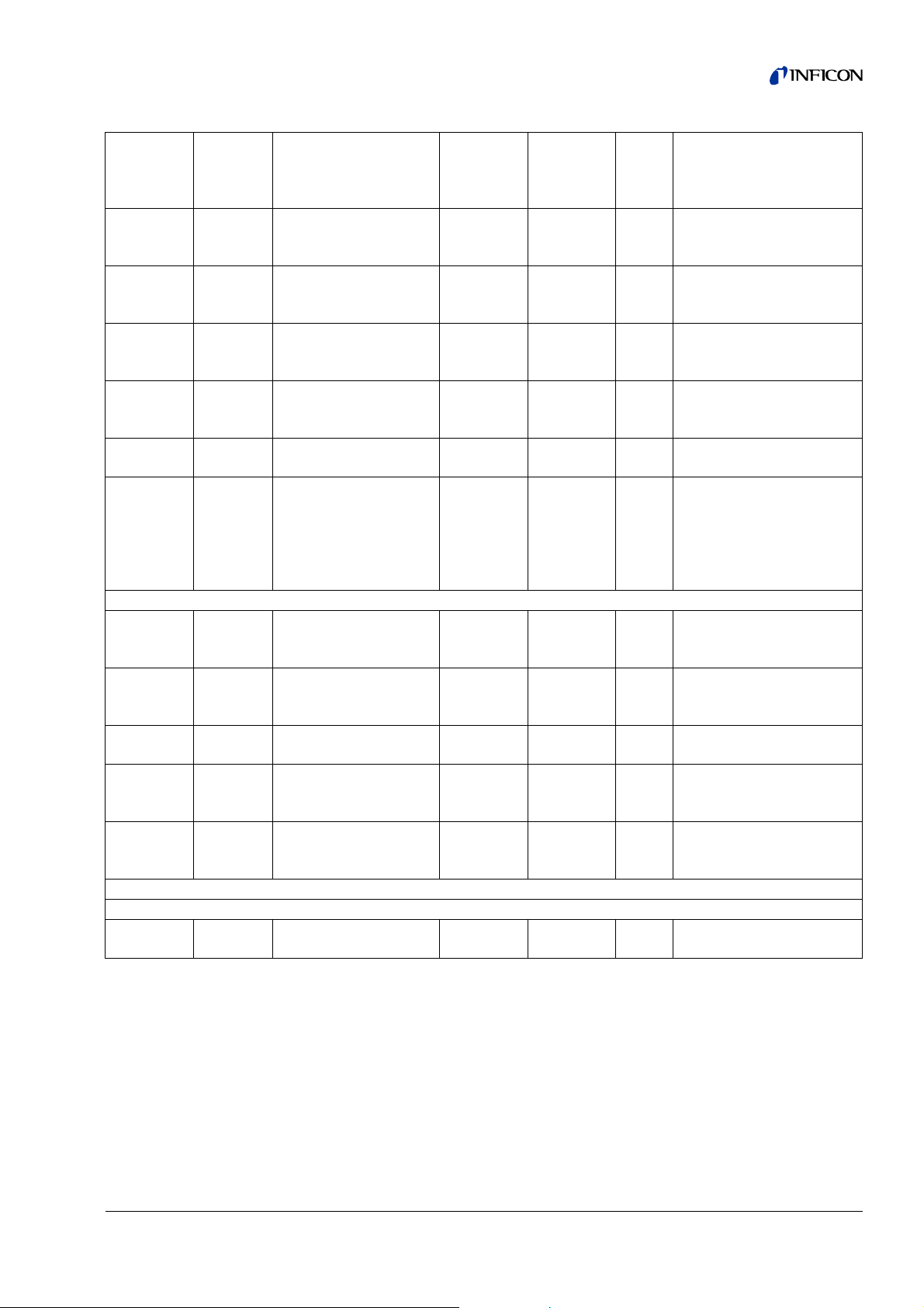
7.3 Maintenance schedule
Failure to perform the maintenance work specified in the maintenance schedule will
void the warranty granted on the mass spectrometer module LDS3000.
Maintenance
steps
Change operating
fluid reservoir
Replace bearing
Turbo molecular pump
Accessories
(recommended)
Clean fan and
check for proper
operation
Clean sniffer valve X III
Calibrate internal
test leak
Operating hours [hrs] / time period
[years]
24 2000 8000 16000 24000 36000
1/4 a 1 a 2 a 3 a
X
2
X
2
1 I and II
X
2
Service
level
Spare part
no.
II and III 200003801
III
III
Internal calibration
External calibration
Leak test MS module
44 Maintenance
Perform internal
calibration
Perform external
calibration
Perform helium leak
test on MS module
X
1
X
1
I
I
XIII
X: based on operating hours or time period
X
: based on operating hours
1
X
: based on time period
2
1: depending on environment and use
Page 45

7.4 Maintenance steps
7.4.1 Change operating fluid reservoir of turbo molecular
pump
1 Shut down mass spectrometer module, see Chapter 8, page 49.
2 Remove turbo molecular pump.
Fig: 5 Tu rbo molecular pump SplitFlow80
1 Cover
2 O-ring
Flooding mass spectrometer and turbo molecular pump
The cover of the operating fluid reservoir cannot be unscrewed unless the reservoir
has been flooded.
1 Disconnect 24 V power supply pack from MSB box.
2 Wait until turbo molecular pump is drained (at least 1 min).
3 Allow the turbo molecular pump to cool down if necessary.
4 Open the ventilation screw slowly.
Turbo molecular pump is flooded until it reaches atmospheric pressure.
3 Operating fluid reservoir
4 Ventilation screw
Maintenance 45
Page 46

Removing old operating fluid reservoir
Face pin wrench, P/N: 551-200
Two screwdrivers
Tweezers
O-ring
Operating fluid reservoir, P/N: 200 003 801
Mass spectrometer and turbo molecular pump flooded.
1 Pay attention to the expiration date of the new operating fluid reservoir.
Danger of poisoning due to harmful substances
The operating fluid reservoir and parts of the turbo molecular pump can be
contaminated with toxic substances that are contained in the pumped media.
► Take suitable safety precautions.
► Decontaminate contaminated parts prior to any maintenance work.
► Dispose of old operating fluid reservoirs in compliance with applicable
regulations.
The new operating fluid reservoir contains a sufficient level of operating fluid.
2 Do not fill in any more operating fluid.
3 Use a face pin wrench to unscrew the cover.
4 Remove old o-ring.
5 Use two screwdrivers to lift out the operating fluid reservoir.
46 Maintenance
Page 47

Fig: 6 Changing the operating fluid reservoir
1 O-ring
2 Operating fluid reservoir
3 Porex rods
4 Ventilation screw
Replacing Porex rods
1 Pull out the old Porex rods (8 pcs) using a pair of tweezers.
Material damage due to cleaning liquids
Cleaning liquids can damage the unit.
► Do not use any cleaning liquids.
► Use a clean, lint-free cloth.
2 Remove any contaminants found on the turbo molecular pump and the cover
using a clean, lint-free cloth.
3 Insert new Porex rods (8 pcs) using a pair of tweezers.
Maintenance 47
Page 48
Inserting a new operating fluid reserv o ir
The new operating fluid reservoir will be positioned correctly when you screw in the
cover:
1 Do not slide in the new operating fluid reservoir into the pump completely, but stop
once you reach the o-ring.
2 Use a face pin wrench to screw in the cover.
Material damage if o-ring is mounted improperly
An improperly mounted o-ring can cause leaks. The unit will experience
malfunctions and become damaged.
► Insert the o-ring carefully.
3 Insert a new o-ring.
4 Screw in the cover (tightening torque 13 Nm +/-10%).
5 Tighten the ventilation screw by hand.
6 Install the turbo molecular pump.
7 Put the mass spectrometer module into operation.
Confirm maintenance work
Control unit installed
Access = Integrator
► Confirm maintenance work on control unit:
A
CCESS CTRL > INTEGRATOR > MAINTENANCE > MAINTENANCE WORK
48 Maintenance
Page 49

8 Taking out of service
8.1 Shutting down the leak detector
1 Switch off the leak detector on the power supply pack.
2 Wait until the turbo molecular pump has stopped running.
8.2 Disposing of the mass spectrometer module
The unit can be disposed of by the user or sent to INFICON.
Information The unit is made of materials that can be reused. By recycling these
materials you reduce waste and environmental impact.
► For disposal, always comply with local and regional environmental and safety
regulations.
8.3 Returning the mass spectrometer module
Danger to health
Contaminated units can damage the health of INFICON's service staff.
► Use the Declaration of Contamination.
1 Fill out the "Declaration of Contamination".
Information We will be happy to send you the form “Declaration of Contamination”
upon request. Xerox copies of the form are permissible.
The Declaration of Conformity is essential to ensure compliance with statutory
requirements and the protection of our employees. Units submitted without an
enclosed Declaration of Conformity will be returned to the sender by INFICON.
2 Attach the form to the unit or enclose it in the unit's packaging.
Taking out of service 49
Page 50
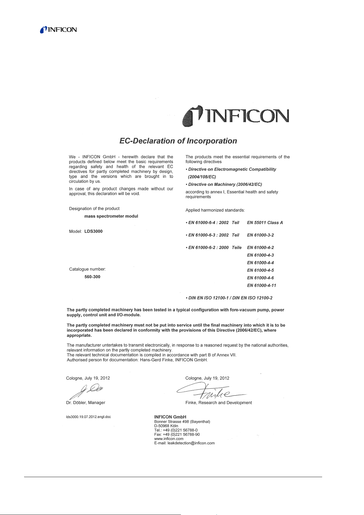
9 Appendix
9.1 EC Declaration of Incorporation
50 Appendix
Page 51

9.2 Declaration of Contamination
INFICON GmbH
Bonner Str. 498,50968 Cologne, Germany
Tel: +49 221 3474 2222 Fax: +49 221 3474 2221
m
zisa01e1-a
Declaration of Contamination
Legally binding declaration:
I/we hereby declare that the information on this form is complete and accurate and that I/we will assume any further costs that may
arise. The contaminated product will be dispatched in accordance with the applicable regulations.
Organization/company
Address Post code, place
Phone Fax
Email
Name
Date and legally binding signature Company stamp
1) or not containing any amount
of hazardous residues that
exceed the permissible ex posure limits
Process related contamination of product:
toxic no 1) yes
caustic no 1) yes
biological hazard n o
yes 2)
explosive no
yes 2)
radioactive no
yes 2)
other harmful substances no1) yes
The service, repair, and/or disposal of vacuum equipment and components will only be carried out if a correctly completed declaration has
been submitted. Non-completion will result in delay.
This declaration may only be completed (in block letters) and signed by authorized and qualified staff.
Copies:
Original for addressee - 1 copy for accompanying documents - 1 copy for file of sender
Harmful substances, gases and/or by-products
Please list all substances, gases, and by-products which the product may have come into contact with:
Trade/product name
Chemical name
(or symbol)
Precautions associated
with substance
Action if human contact
Description of product
Type
Article Number
Serial Number
Reason for return
Operating fluid(s) used (Must be drained before shipping.)
The product is free of any substances which are damaging to
health yes
This form can be downloaded
from our website.
2) Products thus contam i nated will not be ac cepted without written
evidence of deconta mi nation!
www.inficon.com leakdetection.service@inficon.co
Appendix 51
Page 52

INFICON GmbH, Bonner Strasse 498, D-50968 Cologne, Germany
UNITED STATES TAIWAN JAPAN KOREA SINGAPORE GERMANY FRANCE UNITED KINGDOM HONG KONG
Visit our website for contact information and other sales offices worldwide. www.inficon.com
Document: jiqa54d1-b (1301)
 Loading...