

Page 1
PROTOCOL DESCRIPTIONS
Type designation
LDS3000
Product description
Interface Protocols
Catalog no.
from software version
Document no.
560-310, 560-315
MS Module 1.0
jira54e1-a (1212)
Page 2

This document applies to the software version stated on the cover page. If you need
a different version, please contact our sales staff.
Reprint, translation and duplication need to be approved in writing by
INFICON GmbH.
2
Page 3

Content
1 Interface Protocols . . . . . . . . . . . . . . . . . . . . . . . . . . . . . . 6
1.1 Serial Interface Protocols . . . . . . . . . . . . . . . . . . . . . . . . . . . . . . . . . . . 6
1.2 Field Bus Protocols . . . . . . . . . . . . . . . . . . . . . . . . . . . . . . . . . . . . . . . . 6
2 ASCII Protocol . . . . . . . . . . . . . . . . . . . . . . . . . . . . . . . . . 7
2.1 Comparison between ASCCI- and LD protocol . . . . . . . . . . . . . . . . . . 7
2.2 Communication Parameters . . . . . . . . . . . . . . . . . . . . . . . . . . . . . . . . . 7
2.3 Command Format . . . . . . . . . . . . . . . . . . . . . . . . . . . . . . . . . . . . . . . . . 7
2.4 Commands . . . . . . . . . . . . . . . . . . . . . . . . . . . . . . . . . . . . . . . . . . . . . . 8
2.5 Examples . . . . . . . . . . . . . . . . . . . . . . . . . . . . . . . . . . . . . . . . . . . . . . 15
2.6 Error Messages . . . . . . . . . . . . . . . . . . . . . . . . . . . . . . . . . . . . . . . . . 15
3 LDS1000 Protocol . . . . . . . . . . . . . . . . . . . . . . . . . . . . . . 16
3.1 Interface Parameters . . . . . . . . . . . . . . . . . . . . . . . . . . . . . . . . . . . . . 16
3.2 Interface Commands . . . . . . . . . . . . . . . . . . . . . . . . . . . . . . . . . . . . . 16
3.2.1 Main functions . . . . . . . . . . . . . . . . . . . . . . . . . . . . . . . . . . . . 17
3.2.2 Status Requests . . . . . . . . . . . . . . . . . . . . . . . . . . . . . . . . . . 18
3.2.3 Request for Measurement Data . . . . . . . . . . . . . . . . . . . . . . 20
3.2.4 Entry of Instrument Settings . . . . . . . . . . . . . . . . . . . . . . . . . 21
3.2.5 Running of service functions . . . . . . . . . . . . . . . . . . . . . . . . . 23
4 Binary Interface Protocol . . . . . . . . . . . . . . . . . . . . . . . . 24
4.1 Communication Parameters . . . . . . . . . . . . . . . . . . . . . . . . . . . . . . . . 24
4.2 Commands . . . . . . . . . . . . . . . . . . . . . . . . . . . . . . . . . . . . . . . . . . . . . 24
4.3 Error messages . . . . . . . . . . . . . . . . . . . . . . . . . . . . . . . . . . . . . . . . . 27
5 LD Protocol . . . . . . . . . . . . . . . . . . . . . . . . . . . . . . . . . . . 28
5.1 Communication Parameters . . . . . . . . . . . . . . . . . . . . . . . . . . . . . . . . 28
5.2 Command format . . . . . . . . . . . . . . . . . . . . . . . . . . . . . . . . . . . . . . . . 28
5.2.1 Telegram structure . . . . . . . . . . . . . . . . . . . . . . . . . . . . . . . . 28
5.3 Commands . . . . . . . . . . . . . . . . . . . . . . . . . . . . . . . . . . . . . . . . . . . . . 31
5.4 Enumerations . . . . . . . . . . . . . . . . . . . . . . . . . . . . . . . . . . . . . . . . . . . 43
5.5 Error messages . . . . . . . . . . . . . . . . . . . . . . . . . . . . . . . . . . . . . . . . . 48
6 Fieldbus Communication . . . . . . . . . . . . . . . . . . . . . . . 49
6.1 Preface . . . . . . . . . . . . . . . . . . . . . . . . . . . . . . . . . . . . . . . . . . . . . . . . 49
6.2 Setup . . . . . . . . . . . . . . . . . . . . . . . . . . . . . . . . . . . . . . . . . . . . . . . . . 49
6.3 Process Data Mapping for Cyclic Data Transfer . . . . . . . . . . . . . . . . . 49
6.3.1 Write Process Data (PLC-> Leak Detector) . . . . . . . . . . . . . 49
6.3.2 Read Process Data (Leak Detector PLC) . . . . . . . . . . . . . 50
Content 3
Page 4

6.4 Acyclic Data Transfer . . . . . . . . . . . . . . . . . . . . . . . . . . . . . . . . . . . . . 51
6.4.1 Addressing Rules for Acyclic Access . . . . . . . . . . . . . . . . . . . 51
6.5 Hardware Configuration for Profibus . . . . . . . . . . . . . . . . . . . . . . . . . . 52
6.5.1 Assignment of the PROFIBUS Address . . . . . . . . . . . . . . . . 52
6.5.2 Diagnosis with the CU1000 Info Menu . . . . . . . . . . . . . . . . . 53
6.5.3 Serial communication via RS232 (common) . . . . . . . . . . . . . 53
6.5.4 ASCII Protocol specific . . . . . . . . . . . . . . . . . . . . . . . . . . . . . 54
6.5.5 LD Protocol specific . . . . . . . . . . . . . . . . . . . . . . . . . . . . . . . . 54
4 Content
Page 5

Content 5
Page 6

1 Interface Protocols
1.1 Serial Interface Protocols
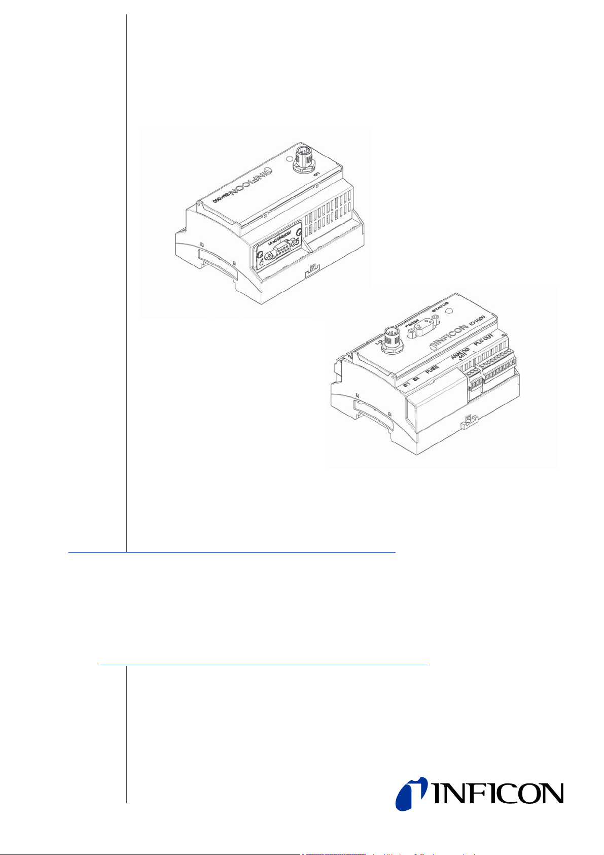
With the IO1000 module you can communicate with the LDS3000 via the following
serial interface protocols:
• ASCII Protocol (enabled by default)
• LD Protocol
If you want to replace a LDS1000 or LDS2010 with a LDS3000 you can also use
• Binary Interface Protocol
• LDS1000 Compatibility Protocol
Do not use the last two protocols for new developments. They have limited
functional range and may not be supported in future.
The serial interface protocol can be selected via DIP switch at the IO module IO1000
or via control unit CU1000. Please refere to appropriate documentation.
1.2 Field Bus Protocols
With the Bus module BM1000 you can communicate with the LDS3000 via the
following field bus protocols:
• PROFIBUS-DP Protocol
• Other fieldbus protocols (PROFINET, DeviceNet, EtherNet/IP, MODBUS RTU,
MODBUS TCP, CANopen, EtherCAT, CC-Link, ControlNet) may be available on
request. Please contact your local INFICON representative.
6 Interface Protocols
Page 7

2 ASCII Protocol
2.1 Comparison between ASCCI- and LD protocol
ASCII- and LD protocol have nearly the same functional range, but each of them
have some advantages and disadvantages :
ASCII protocol:
Advantages:
• human readable
• easy to use with simple terminal program
Disadvantages:
• No checksum, therefor lower data security
• PC/ PLC software must convert numerical values from ASCII string to binary
• Lower efficiency (for example: 8 data bytes for one float value)
LD protocol:
Advantages:
• Leak detector status always transmitted in each slave telegram
• High data security due to CRC checksum
• Binary transmission of numerical values – no conversion needed in PC/ PLC
software
• High efficiency (for example: 4 Byte data bytes for one float value)
Disadvantages:
• Not human readable
• Not useable with simple terminal program
2.2 Communication Parameters
Data format
Baudrate 19.200, 8 data bits, 1 stop bit, no parity
2.3 Command Format
In ASCII protocol any command starts with « * » (ASCII code 42dec/2Ahex) and is
finished with the end sign CR (ASCII code 13dex/0Dhex). There is no differentiation
between upper and lower case. A blank is required between the command and the
parameter, no other blanks are allowed.
There is a short and an extended form of the command. Either the short or the
extended command must be used, no other abbreviations are allowed (The short
form is here written in capitals but the SW don’t difference upper and lower cases).
Command Words have to be separated by a colon. A command can be composed
of up to three words. Parameters have to be separated by a comma.
ASCII Protocol 7
Page 8

Each command is answered with the requested data, „ok“ or „EXX“ (in case of an
error). For a list of all error messages 2.6. The transmission can be cancelled and the
receive-buffer will be cleared with ESC (ASCII code 27dec/1Bhex), ^C (ASCII code
3dec/03hex) or ^X (ASCII code 24dec/18hex).
Some commands can be used as queries, some can be used to set menu parameter
and some can be used for both. A query is marked by a „?“ (ASCII code 63dec/
3Fhex) after the command; for setting data the command has to be followed by the
new value to be set.
Parameter can be Boolean or numerical:
<b> Boolean 0 / 1 or OFF / ON
<No> Numeric representation format: integer, real (15.6) or exponential (4.5
Format: [space] [sign] [ddd] [.] [e[sign]ddd] (d:digit)
Notice Always use a point as the decimal marker. If a comma is used during
numerical data entry, the conversion of the number is cancelled at this
point and only the integer part of the number will be used.
Timing recommendations for the PC/PLC - Program:
Sample rate > 100 ms
Timeout between request to and answer from LDS3000: 1500 ms
After sending a command the answer must be waited for before sending a new
command. Otherwise the receive buffer may be overwritten.
2.4 Commands
Relates to
LD cmd. no.
*CLS Clear Error 5 S
*IDN Identification
:CRC check sum 320 R
:DEVice name of instrument 301 R
:VERsion software version MSB 310 R
:SERial serial-number leak detector R
:TURBO software version TMP controller 315 R
:DIP1 MSB DipSwitch 1 (binär) 321 R
:DIP2 MSB DipSwitch 2 (binär) 321 R
:CUversion software version control unit 314 R
:IOversion software version I/O modul 313 R
:TCHARDware hardware version TMP controller 316 R
:TCNAME TMP controller name 317 R
:BMVersion software version Bus modul R
:BMSerial serial-number Bus modul R
:BMNETType Bus module network type R
*STATus
status of LDS2010 (
EMIOFF)
ACCL, STBY, MEAS, CAL, ERROR,
Status
word
-7
)
Read /
R
Set
8 ASCII Protocol
Page 9

:CAL
:CALHist
:ERRor
:ERRHist
status of calibration
DYNCAL, CLOSE, FAIL)
(IDLE, INTCAL, EXTCAL,
Last error history entry
Factor, Test leak, Anode voltage, Mass, Date,
Time, Cathode, State
1 Calibration history entry 1 (newest)
2 Calibration history entry 2
…
10 error history entry 10 (oldest)
current number of error / warning („NO ERROR/
WARNING“, 3-digit failure number)
Actual error history entry
In LDS2010 compatibility mode:
dd.mm.yy hh.mm Exx
Exx is error number from LDS2010 error number
group
All other compatibility modes:
ListNo 'ERR' or 'WRN' ErrNo ErrValue(float),
year/month/day hour:min:sec 'SwOnCnt:'
SwitchOnCnt 'OnTm:' MinSinceStart
“WRNxxx vvv yy/mm/dd hh:mm:ss SwOnCnt:
zzz OnTm: ttt“
or
“ERRxxx vvv yy/mm/dd hh:mm:ss SwOnCnt: zzz
OnTm: ttt“
Relates to
LD cmd. no.
260 R
275 R
290 R
290 R
Read /
Set
xxx: Error or warning number from LDS3000
error number group
vvv: Measured value
1 error history entry 1 (newest) 290 R
2 error history entry 2 290 R
.....
16 error history entry 16 (oldest) 290 R
:MODE actual vacuum mode (VAC, SNIFF) 401 R
:ZERO Zero (ON, OFF) 6 R
status of valves
0...255 as 8-bit binary number
:VALVE
(0:off; 1:on)
Bit0: Test leak
449 R
Bit4: Sniffer valve
Bit1: Gas ballast
status of trigger
:TRIGger
S1,S2,S3,S4 with S1…S4 is “ON” or “OFF”
385 R
depending of the states of trigger1 to trigger4
ASCII Protocol 9
Page 10

Relates to
LD cmd. no.
:PREAMPRESi
stor
:CAThode
:BUSModule
:EXCEPtion Exception Code of Bus module as hex value R
:ERRORCnt
:ADDRess Field bus address R
:BAUDrate Baud rate at field bus R
*READ leak rate in current unit 128 R
:ATM*cc/s leak rate in Atm*cc/s --- R
:G/a leak rate in g/a (only in sniff) --- R
:MBAR*l/s leak rate in mbar*l/s 129 R
:PA*m3/s leak rate in Pa*m3/s --- R
:PPM leak rate in ppm (only in sniff) --- R
:TORR*l/s leak rate in Torr*l/s --- R
*STArt start 1 S
*STOp stop 2 S
*CAL :STOP abort calibration 11 S
:INT start internal calibration 4 S
:DYN start external dynamic calibration 4 S
:EXT start external calibration 4 S
:CLOSED report test leak closed (ext. cal. only) 11 S
*ZERO switch zero on 6 S
:ON switch zero on 6 S
:OFF switch zero off 6 S
*MEAS
:P or :P1 P1 pressure in current unit 130 R
:ATM P1 pressure in atm --- R
:MBAR P1 pressure in mbar 83 R
:PA P1 pressure in Pa --- R
:TORR P1 pressure in Torr --- R
:P2 P2 pressure in current unit 132 R
:ATM P2 pressure in atm --- R
:MBAR P2 pressure in mbar 133 R
:PA P2 pressure in Pa --- R
currently used resistance of pre-amplifier
(13M, 470M, 15G, 500G, 13M_FIXED,
470M_FIXED, 15G_FIXED, 500G_FIXED)
actual state of the cathode
OFF, ON1 (fix cathode 1), ON2 (fix cathode 2),
AUTO1 / AUTO2 (automatic switching; cathode
1 respectively 2 actual active)
Status Bus-Modul
“SETUP”,"NW_INIT”,
"WAIT_PROCESS","IDLE",
"PROCESS_ACTIVE","ERROR", "UNKNOWN",
"EXCEPTION"
Four error counters, format “a,b,c,d”
a: Discarded commands
b: Discarded responses
c: Serial reception errors
d: Fragmentation errors
502 R
530 R
330 R
Read /
R
Set
10 ASCII Protocol
Page 11

Relates to
LD cmd. no.
:TORR P2 pressure in Torr --- R
:P3 P3 pressure (only for service) 134 R
:P4 P4 pressure (only for service) 135 R
:UVV preamplifier voltage [V] 202 R
:MIAP anode potential [V] 167 R
:MIKP cathode potential [V] 168 R
:MISP suppressor potential [V] 169 R
:MIAKP anode-/cathode potential [V] 170 R
:U15N -15 V supply [V] 211 R
:U15P +15 V supply [V] 210 R
:U24 24 V supply [V] 200 R
:U24IO 24 V supply IO [V] 213 R
:U24IO_OUT 24V power out IO [V] 219 R
:U24PI 24 V power out pirani [V] 214 R
:U24PWR1_2 24 V power out12 [V] 215 R
:U24PWR5_6 24 V power out56 [V] 217 R
:U24RC 24V_2 power out RC [V] 212 R
:U5 +5 V supply [V] 218 R
:TEMPeratur
:Amplifier preamplifier temperature [°C] 166 R
:Electronic electronic temperature [°C] 165 R
:TCElectronic TMP electronic temperature [°C] 144
:TCPump TMP temperature bottom [°C] 143 R
:TCBearing TMP temperature bearing [°C] 145 R
:TCMotor TMP electronic temperature [°C] 146 R
:TURBO
:Frequency TMP frequency [Hz] 138 R
:Voltage TMP voltage [Hz] 150 R
:Current TMP current [A] 151 R
:Power TMP power [W] 139 R
:ANALOGOUT
1
:ANALOGOUT
2
Output voltage analog output channel 1 221 R
Output voltage analog output channel 2 221 R
Read /
Set
ASCII Protocol 11
Page 12

*CONFig
Relates to
LD cmd. no.
state of the PLC inputs as 16-bit binary number;
inactive=0, active=1
Byte 0, Bit 0: PLC In 1
Byte 0, Bit 1: PLC In 2
Byte 0, Bit 2: PLC In 3
Byte 0, Bit 3: PLC In 4
Byte 0, Bit 4: PLC In 5
Byte 0, Bit 5: PLC In 6
:DIGITALIN
:IMess Unfiltered ion current [A] 1568 R
:CALleak leak rate of test leak
:INT internal test leak in mbarl/s 394 R/S
:EXTVac
:EXTSniff external test leak in sniff mode in current sniff unit 392 R/S
:CALREQ
:CAThode
:RS232 Protocol (ASCII, LD, LDS1000) 26 R/S
:MASS mass (2,3,4) 506 R/S
:MFAE actual anode potential reference [V] 167 R
:M2 anode potential reference for mass 2 [V] 433 R/S
:M3 anode potential reference for mass 3 [V] 434 R/S
:M4 anode potential reference for mass 4 [V] 435 R/S
:MODE operating mode (VAC, SNIFF) 401 R/S
:RECorder
:LINK1
:LINK2
Byte 0, Bit 6: PLC In 7
Byte 0, Bit 7: PLC In 8
Byte 1, Bit 0: PLC In 9
Byte 1, Bit 1: PLC In 10
Byte 1, Bit 2: DIP_1
Byte 1, Bit 3: DIP_2:
Byte 1, Bit 4: DIP_3:
Byte 1, Bit 5: DIP_4
Byte 1, Bit 6: DIP_5
external test leak in vacuum mode in current vac
unit
calibration request (OFF,ON);
with read: (OFF, ON_REQUESTED,
ON_NOTREQUESTED)
target state of the cathode
OFF (not saved after power loss)
ON1 (fix cathode 1)
ON2 (fix cathode 2)
AUTO (automatic switching cathode)
with read: AUTO1 / AUTO2: Auto with cathode 1
respectively 2 actual active
Function at analog output channel 1
(OFF, P1, P2, MANT, EXP, LR_LIN, LR_LOG,
LR_LOG_H, EXTERN)
Function at analog output channel 1
(OFF, P1, P2, MANT, EXP, LR_LIN, LR_LOG,
LR_LOG_H, EXTERN)
261 R
390 R/S
419 R/S
530 R/S
222 R/S
222 R/S
Read /
Set
12 ASCII Protocol
Page 13

Relates to
LD cmd. no.
:SCALE Analog out scaling 223 R/S
:UPPEREXP Upper Exponent (in mbar*l/s) for analog out 224 R/S
:TRIGger1 trigger1 in current unit 384 R/S
:ATM*cc/s trigger1 in Atm*cc/s --- R/S
:G/a trigger1 in g/a --- R/S
:MBAR*l/s trigger1 in mbar*l/s 385 R/S
:PA*m3/s trigger1 in Pa*m3/s --- R/S
:PPM trigger1 in ppm --- R/S
:TORR*l/s trigger1 in Torr*l/s --- R/S
:TRIGger2 trigger2 in current unit 384 R/S
:ATM*cc/s trigger2 in Atm*cc/s --- R/S
:G/a trigger2 in g/a --- R/S
:MBAR*l/s trigger2 in mbar*l/s 385 R/S
:PA*m3/s trigger2 in Pa*m3/s --- R/S
:PPM trigger2 in ppm --- R/S
:TORR*l/s trigger2 in Torr*l/s --- R/S
:TRIGger3 trigger3 in current unit 384 R/S
:ATM*cc/s trigger3in Atm*cc/s --- R/S
:G/a trigger3in g/a --- R/S
:MBAR*l/s trigger3in mbar*l/s 385 R/S
:PA*m3/s trigger3in Pa*m3/s --- R/S
:PPM trigger3in ppm --- R/S
:TORR*l/s trigger3in Torr*l/s --- R/S
:TRIGger4 trigger4 in current unit 384 R/S
:ATM*cc/s trigger4 in Atm*cc/s --- R/S
:G/a trigger4 in g/a --- R/S
:MBAR*l/s trigger4 in mbar*l/s 385 R/S
:PA*m3/s trigger4 in Pa*m3/s --- R/S
:PPM trigger4 in ppm --- R/S
:TORR*l/s trigger4 in Torr*l/s --- R/S
:UNIT
:LRVac
:LRSniff
leak rate unit vac mode (ATM*cc/c, MBAR*l/s,
PA*m3/s, TORR*l/s)
leak rate unit sniff mode (ATM*cc/c, MBAR*l/s,
PA*m3/s, TORR*l/s, ppm, g/a)
431 R/S
432 R/S
:Pressure pressure unit (ATM, MBAR, PA, TORR) 430 R/S
:ZEROTime zerotime in seconds (0,5…30s) 411 R/S
:CORSTBY R/S
:ZEROSTART zero at start (OFF, ON) 409 R/S
:SPEEDTMP rotation speed of TMP in Hz 501 R/S
:BUTSniffer button of the sniffer probe (OFF, ON) 412 R/S
:LRFilter filter switch-over threshold in current leak rate 403 R/S
Read /
Set
ASCII Protocol 13
Page 14

*HOUR
*FACtor
Relates to
LD cmd. no.
assignment of PLC-outputs
"OPEN", “INV_OPEN”,
"TRIGGER_1","INV_TRIGGER_1",
"TRIGGER_2","INV_TRIGGER_2",
:1 or :1_2
:2 or :3_4
:3 or :5_6
:PLCOUTLINK
:PLCINLINK
:DECADEZero
:DATE date TT,MM,JJJJ 450 R/S
:DEVice operating hours of device 142 R
:POWer time since switching on (in minutes) 147 R
:TIME time hh,mm 450 R/S
:TURBO operating hours of TMP 140 R
:TC operating hours of converter 141 R
:FACSniff sniff factor 523 R/S
:FACMachine machine factor 522 R/S
:RESistor resistor factor 500 G / 15 G 504 R/S
:4 or :7_8
:5 or :9_10
:6 or :11_12
:7 or :13_14
:8 or :15_16
:1
:2
:3
:4
:5
:6
:7
:8
:9
:10
"TRIGGER_3","INV_TRIGGER_3",
"TRIGGER_4","INV_TRIGGER_4",
"READY","INV_READY",
"WARNING","INV_WARNING",
"ERROR",”INV_ERROR”,
“CAL_ACTIVE",“INV_CAL_ACTIVE",
"CAL_REQUEST",”INV_CAL_REQUEST”,
"RUN_UP", “INV_RUN_UP”,
"ZERO_ACTIVE", "INV_ZERO_ACTIVE",
“EMISSION_ON", “INV_EMISSION_ON”
"MEASURE", “INV_MEASURE”,
"STANDBY", “INV_STANDBY”,
"SNIFF", “INV_SNIFF”
assignment of PLC-inputs
(„NOT_USED“,
„DYN_CAL“, „INV_ DYN_CAL “,
„EXT_CAL“, „INV_ EXT_CAL “,
„INT_CAL“, „INV_ INT_CAL “,
„SNIFF“, „INV_ SNIFF“,
„START“, „INV_ START “,
„STOP“, „INV_ STOP “,
„ZERO“, „INV_ZERO“,
„ZERO_PULS”, „INV_ ZERO_PULS”
“CLEAR”, “INV_CLEAR”,
“GAS_BALLAST”, “INV_ GAS_BALLAST
”,"SEL_DYN_NORM", "INV_SEL_DYN_NORM",
"START_STOP", "INV_START_STOP",
„KEY1”, „INV_ KEY1”,
„KEY2”, „INV_ KEY2”,
„KEY3”, „INV_KEY3”,
)
zero function
„NORM“,(„1-2“, “2-3“, „19/20“, „2“, „3-4“)
263 R/S
438 R/S
410 R/S
Read /
Set
14 ASCII Protocol
Page 15
Relates to
LD cmd. no.
:CALSniff calibration factor sniff 521 R/S
:CALVac calibration factor vacuum 520 R/S
*SERVICE
:READBuffer Read service buffer
*STARTFLA
SH
*RST :FACTORY Sets all parameters to factory default 1161 S
:CALHistory Clears calibration history 1161 S
:ERRORHistory Clears error history 1161 S
Flash-Update starten 2619 S
1300 ..
1310
2.5 Examples
Command answer
*stat? (CR) MEAS (CR) mode
*status? (CR) MEAS (CR) mode
*read? (CR) 2.876E-7 (CR)
*read:pa*m3/s? (CR) 2.876E-6 (CR) leak rate in a different unit
*start (CR) OK (CR) start measurement
*conf:trig1? (CR) 1.0E-9 (CR) retrieve trigger 1
*conf:trig1 2.0E-9 (CR) OK (CR) set trigger 1
leak rate according to
programmed unit
Read /
R
Set
2.6 Error Messages
Message Meaning
OK command completed
E01 wrong command start (no „*“)
E02 illegal blank
E03 command word 1 illegal
E04 command word 2 illegal
E05 command word 3 illegal
E06 control by RS232 not enabled
E07 argument faulty
E08 no data available
E09 error buffer overflow
E10 command invalid
E11 query not allowed
E12 only query allowed
E13 not yet implemented
ASCII Protocol 15
Page 16

3 LDS1000 Protocol
3.1 Interface Parameters
So that the connected instruments (PC) may communicate with the LDS3000, it is
required to set-up the interface parameters on the connected instruments.
The settings for the LDS3000 are:
9600 baud, 8 data bits, no parity, 1 stop bit, No handshake and CR as the end sign.
3.2 Interface Commands
The list is ordered to their functions.
The interface commands are composed of the following parts:
Structure
COMMAND <cr>
COMMAND PARAMETER <cr> COMMAND PARAMETER,
PARAMETER <cr>
<cr>: Carriage return (13d)
Example
STOP <cr> G10 <cr>
U24.0 <cr>
There exist several types of command. The main functions of the leak detector are
in plain text which points to the function. For example, the command "START <cr>"
starts the measurement mode. In response to this command, the PC receives "OK
<cr>". A list of the main functions is provided in Chapter 1.4.1.1.
Besides this, conditions may be queried through commands which begin with a "S"
for "Status" and which have a parameter attached. A list of all status query
commands is given in Chapter 1.4.1.2.
Measurement quantities can be queried through the command "G" for "Get", for
example: "G1<cr>". The LDS 3000 will then respond by outputting the current leak
rate. All measurement quantities which may be queried are listed in Chapter 1.4.1.3.
If the entry of settings is required in the way normally performed through the menus
shown on the Control Unit, the command "U" for "Update" may be used to change
the corresponding parameter. The parameter itself may be output via the serial interface through the command "Q" for "Query". For example, "U 0, 1.0E-04<cr>"
changes the
level for the first trigger to 1E-4. The commands used to set and query parameters
are listed in Chapter 1.4.1.4.
Through "Q 0<cr>" the trigger level can be read.
Less frequently used functions which normally will only be run for servicing can be
invoked through the command "F" for "Function". For example: "F10<cr>" switches
the emission off. A list of these functions is given in Chapter 1.4.1.5.
During servicing the command "V" for "Valves" may be used to switch the valves. For
example: "V 1,0 <cr>" opens the internal calibrated leak.
16 LDS1000 Protocol
Page 17
Through the reset character <ESC> (27d or 1Bh) without <cr> the interface of the
LDS 1000 may be reset back to a defined state. A received string which might be
processed at that moment is erased and its processing is terminated. Receiving of
the <ESC> character is acknowledged by "OK<cr>" (In the case of the "TERMINAL"
program from Microsoft the character "O" is not displayed when the local echo is on).
Thereafter, the interface is ready to receive. Through this character its is easily
possible to check whether or not the data link has been properly installed.
3.2.1 Main functions
Command Meaning
Reply
from the
LDS1000
Equivalent to key
or PLC input
LR Leak rate, date, time, output status
Start measurement mode,
START
suppress the background which
was measured upon operating
OK MEAS active
START
Stop the measurement mode,
STOP
display the current background
OK MEAS inactive
level
ZERO mode on, suppress the
ZERO
background which was measured
OK ZERO active
upon operating ZERO
ZERO mode off, display the
ZERO OFF
background which was measured
OK ZERO inactive
upon operating ZERO
x1)
CAL
CLEAR
X1*)
Calibration: In the STANDBY mode, the internal calibration is started.
Internal/external calibration OK CAL
Interrupt calibration/erase error
status
OK CLEAR active
In the MEASURE mode, the external calibration is started. The status of the external
calibration may be queried through S12. Sequence of commands for external calibration:
Reply
Command
from the
Meaning
LDS1000
The LDS1000 enters the measurement
1START OK
mode, the calibrated leak must be opened,
wait until the signal has stabilised.
2 CAL OK External calibration is being started.
3 S12 1 External calibration is running.
4S12 2
Calibrated leak must be closed, wait until
the signal is stable.
5 CAL OK Calibration is continued.
Calibration complete, the LDS1000 is in
6S12 0
the measurement mode, the instrument is
running in the MEASUREMENT mode.
The internal calibration process is run automatically. There after, the LDS3000 will
be in the STANDBY mode.
LDS1000 Protocol 17
Page 18

3.2.2 Status Requests
Besides the main functions, there exist a variety of request commands for outputting
the status which reflect the current state of the LDS3000.
For example: "S 2<cr>". The LDS3000 replies by: "00000110<cr>", for example. This
means that the LDS3000 is in the "Measure" mode.
Status Information:
S2
S3 Relay status xxxx xxxx (always 8 characters) (Byte 0 first)
S4 Exceeding of
S6 Key switch status
S10 Current error
S12 External CAL status
Meaning Representation
xxxx
xxxx
Byte 0
Byte 1
Instrument status
(number)
measurement range
limits (leak rate)
Byte 2
Byte 3
Byte 4
Byte 5
Byte 6
BYTE 7
Byte 0: < TRIG 1
Byte 1: < TRIG 2
Byte 2: < TRIG 3
Byte 3: < TRIG 4
Byte 4: Ready
Byte 5: always 0
Byte 6: CAL-REQUEST
Byte 7: no ERROR
Useful when leak rates are uueried through the
command G1.
0 - within the measurement range
1 - Underrange. The actual leak rate is below the
output value. This may occur in particular after
activating the Zero function or when restricting
the measurement range through "MANUAL".
2 - Overrange
0 - Key switch defective
1 - No key
2 - Key 1
3 - Key 2
4 - Key 3
0 - no errorr / warning > 0 otherwise error
number (not yet acknowledged). See TH ???
Chapter ????. If the error is no longer present,
the message may be erased through "CLEAR".
Is used to monitor the calibration process with
an external calibrated leak. See also TH ???
Chapter ???.
0 - inactive
1 - active; calibration is running at the moment.
2 - "Close" The external calibrated test leak
must be closed and acknowledged through
CAL after the signal has stabilised.
(always 8 characters) (Byte 0
right)
0 = VAC 1 = SNIFF
always 0
0 = STANDBY 1 = MEASURE
0 = CAL inactive 1 = CAL active
refers to external calibration 0 =
STANDARD 1 = DYNAMIC
-ACCELERATION
FAIL
18 LDS1000 Protocol
Page 19

Meaning Representation
"Zero"
S14 ZERO status
0 - no correction
1 - a constant leak rate is suppressed
See command Q/U 19
S18 CAL request status
0 - no request
1 - request is present (temperature difference of
5°)
Serviceinformationen, die bei Rückfragen oder im Fehlerfall zur Lösung eines
Problems beitragen können
S30 software version e.g.:1.00
S31 Serial number xxxxxxxxxxxxxxx
S32 Operating hours counter xxxxxx
xy (always 2 characters)
"1" valve open
S35 Valve position
"0" valve closed
Byte x Valve for calibrated leak
Byte y Sniffer valve
See TH ??? Chapter ???.
xxxxxxx (always 7 signs) (Byte 0 first)
Byte 0: Input 7
Byte 1: Input 6
S39
Status of the remote
contol inputs
Byte 2: Input 5
Byte 3: Input 4
S41 Preamplifier
S42 Turbo pump
Byte 4: Input 3
Byte 5: Input 2
Byte 6: Input 1
Byte 7: always 0
Amplification of the preamplifier can be changed
through F26 … F30. xy
x: Status: 0 - auto, 1 - manuell
y: Amplification: 0 - 13M; 1 - 470M; 2- 15G; 3 0,5T
xxxxx (Byte 0 first)
Byte 0: speed too low
Byte 1: speed too high
Byte 2: always 0
Byte 3: FAIL converter ("1"-Error)
Byte 4: running up/ acceleration
LDS1000 Protocol 19
Page 20

Meaning Representation
S43 Emission control
S51
S52 Calibration M4 Sniff
S70
S72
S73
Calibration factor M4
Vacuum
Output the number of the
current interface error
Output the number of the
current error message
(except interface errors)
Output the number of the
wrong parameter
xxxxx (Byte 0 first)
Byte 0: Status number
Byte 1: Nominal status
0- off, 1 - Standby, 2 -on
Byte 2: Actual status
0 - off, 1 - Standby, 2 -on
Byte 3: Cathode
1 - Cathode 1, 2 - Cathode 2
e.g.: 7.492E-13
e.g.: 7.492E-13
"ok", if no error is present.
e.g.: ER53 12.Oct. 11:50
"ok", if no error is present.
3.2.3 Request for Measurement Data
Measurement data can be queried through the command G for "GET".
Command Meaning Representation
G6
G7
G8
G9
G10 Anode potential (MIAP) in volts. e.g.: 457
G11
G12
G13
G19
Measurement data for servicing:
G6
G7 Preamplifier signal (EVS) in volts. e.g.: 01.456
Forevacuum pressure (PV) in
volts (1000 mbar: 10.0V).
Preamplifier signal (EVS) in
volts.
Electronics temperature (ELTA)
in °C
Amplifier temperature (EVSTA)
in °C
Cathode potential (MIKP) in
volts.
Suppressor potential (MISP) in
volts.
Anode-Cathode potential
(MIAKP) in volts.
Speed of the turbopump (TMP)
in Hz.
Forevacuum pressure (PV) in volts
(1000 mbar: 10.0V).
e.g.: 02.629
e.g.: 01.456
e.g.: 23.5
e.g.: 29,2
e.g.: 378
e.g.: 330
e.g.: 79
e.g.: 1048
e.g.: 02.629
20 LDS1000 Protocol
Page 21

Command Meaning Representation
G8
G9
G10 Anode potential (MIAP) in volts. e.g.: 457
G11 Cathode potential (MIKP) in volts. e.g.: 378
G12
G13
G19
Electronics temperature (ELTA) in
°C
Amplifier temperature (EVSTA) in
°C
Suppressor potential (MISP) in
volts.
Anode-Cathode potential (MIAKP)
in volts.
Speed of the turbopump (TMP) in
Hz.
3.2.4 Entry of Instrument Settings
The settings of parameters in the control modus "RS232" may be changed via the
command "U" for update when the jumper XJ1 has been set to RS232. The parameters may be output via the serial interface through the command "Q" for query.
Forexample, "U0, 1.0E-4<cr>" changes the level for the first trigger to 1.0x 10⁻⁴.
Through "Q0<cr>" the trigger level can be read.
The settings are each explained in the Technical Handbook jina50e1-a.
In order to use the commands U51 to U66 the password needs to be entered.
e.g.: 23.5
e.g.: 29,2
e.g.: 330
e.g.: 79
e.g.: 1048
Command Meaning Representation
Q/U0 Trigger 1 in current unit e.g.: 1.0E-5
Q/U1 Trigger 2 in current unit e.g.: 1.0E-5
Q/U2 Trigger 3 in current unit e.g.: 1.0E-5
Q/U3 Trigger 4 in current unit e.g.: 1.0E-5
x, y (always 2 signs)
Q4 Output the operating mode
Select operating mode This setting
U4
Q/U7
Q/U8
Q10 Always 0
Q11 Limit-Low in current unit e.g.: 1.0E-8
Q12 Limit-HIGH in current unit e.g.: 1.0E4
Q/U13 Machine factor for VAC e.g.: 1.0E0
is not saved when switching the
mains power off.
Sensitivity Threshold. Leak rate in
current unit at which the sensitivity
(averaging time) is
Zero time in seconds (period of
time for which the leak rate signal
must remain below the saved
background level until the saved
background level itself is
corrected).
switched over.
X: 0 – SPS, 1 - RS232
Y: 0 – VAC. 1 - SNIFF
0 - VAC
1 - SNIFF
e.g.: 1.0E-10
e.g.: 5
LDS1000 Protocol 21
Page 22

Command Meaning Representation
Q/U14 Correction factor for SNIFF e.g.: 1.0E0
Operating mode for ext. CAL The
Q/U16
Q/U19
Q/U20
Q/U21 Date
Q/U22 Time e.g.: 14:40:07
setting is not saved when switching
off the mains power.
Request for CAL (Enable CAL
message for a temperature
difference of 5° C).
Mass of the gas which is detected
in the mass spectrometer
Q/U24 Unit (unit of measurement for
pressure and leak rate in VAC
and SNIFF)
0 - with autotune
1- dyn. CAL without autotune
0 - off
1 - on
2 , 3, 4
e.g.: 4
e.g.: 24.Nov04
Abbreviations for the months:
Jan May Sep Feb Jun Oct Mar
Jul Nov Apr Aug Dec
0 - mbar and mbar l/s
1 - Pa and Pa m
3/s
2 - atm and atm cc/s
3 - mbar and g/a
ppm and g/a is not available for
VAC
Q/U27 Leak rate of the internal
calibrated leak (always in mbar
4 - mbar and ppm
5 - Torr and Tor l/s
e.g.: 1.0E-7
9.9E-1 for not available
l/s
Q/U28
leak rate of the external
calibrated leak
e.g.: 1.0E-5
9.9E-1 for not available
Q/U31 Number of suppressed decades 0 - 1 to 2 decades
1 - 2 to 3 decades
2 - 3 to 4 decades
3 - 2 decades
4 – complete value
5 - 19/20 of value
22 LDS1000 Protocol
Q/U32 Zero suppression when START
U45
Q/U56 Factor 500G - 15G
Q/U57
Compatibility
Mode
MSV anode potential for masse 2
in volts
0 - off
1 - on
2 – LDS2010-Mode
3 – LDS3000-Mode
e.g.: 890
Page 23

Command Meaning Representation
Q/U58
MSV anode potential for masse 3
in volts
e.g.: 590
Q/U59
Q/U66 Always 0
MSV anode potential for masse 4
in volts
3.2.5 Running of service functions
These function calls are not required for normal measurement operations. They are
thus all protected by the password (see command U5) with the exception of function
F3. The control mode must be set to RS232.
Command Meaning Representation
Parameter RESET, resetting of all
F3
F17 Switch on cathode 1
F18 Switch on cathode 2 (MEK2 = on)
parameters (except internal test
leak and LCD-contrast) to factory
defaults. Erase error memory.
Hardware RESET (same as when
switching OFF and the ON again)
e.g.: 455
LDS1000 Protocol 23
Page 24

4 Binary Interface Protocol
4.1 Communication Parameters
Data format
Baudrate 19.200, 8 data bits, no parity, 1 stop bit
float 4 Bytes, IEEE754 (± 10
1 Byte Exponent/Sign
unsigned long int [ulint]: 4 Bytes, integer without algebraic sign MSB …
LSB (0 … 4294967295)
unsigned short int [usint]: 2 Bytes, integer without algebraic sign MSB,
LSB (0 … 65535)
signed short int 2 Bytes, integer without algebraic sign MSB, LSB
(-32768 … 32767)
unsigned char [uchar]: 1 Byte, integer without algebraic sign (0 … 255)
unsigned char [uchar]: 1 Byte, character ASCII Code (0 … 255)
4.2 Commands
On every command you have to acknowlede with a cmd number. In case of error
instead of a cmd number a error byte ( 230) is transfered.
±38
), 3 Byte Mantissa,
Nr Name Description Parameter Data
2 GetPv Fore vacuum pressure
5 GetDeviceID Device type LDS2000Plus: 31dec.
8
9
36
37
40
41
50
51
54 GetCal Read calibration state 0-int.Cal; 1-ext.Cal
55 SetCal Start / Stop calibration 0-int.Cal; 1-ext.Cal
GetGasballast
SetGasballast
GetCalFac
SetCalFac
GetMass
SetMass
GetZero
SetZero
Gas ballast valve
Calibration factor
Measure mass [uchar, 2/3/4 for mass 2/3/4]
Zero (suppress background)
Byte 0: unit (0-mbar,
1-Pa, 2-atm, 3-Torr)
Byte 0: 0-Vacuum;
1-Sniff
Pv [float]
Byte 0: 0-off, 1-on,
2- main fail safe -on
Factor [float]
0-off
1-on
0-inactiv; 1-active; 2-wait for
calibrated leak close (only
at external calibrations)
0-stop; 1-start; 2-finish (
TL close; only at external
calibrations)
24 Binary Interface Protocol
Page 25

Nr Name Description Parameter Data
Byte 0: 1...4 for Trigger
1...4
56
57
GetTrigger
SetTrigger
Set / read trigger
Byte 1: Einheit: 0mbar*l/s, 1-Pa*m³/s,
2-atmcc/s, 3-Torrl/s;
In sniff mode additional
4-ppm and 5-g/a
[float]: Trigger value
58
59
60
61
62 GetErrorCode Read actual error number
63 SetClearError Quit error / cancel calibration
66
67
68
69
GetOpMode
SetOpMode
GetStBy
SetStBy
GetTL
SetTL
GetFilterSetPoint
SetFilterSetPoint
Set / read operation mode
Stand-By read / set
Value of the calibrated leak
read / set
Leak rate for switching the
averting time
Byte 0: 0-int.TL;
1-ext.TL-vac;
2-ext.TL-sniff
Byte 1: unit: 0-mbar*l/s,
1-Pa*m³/s, .2-atmcc/s,
3-Torrl/s;
In sniff mode
additionally: 4-ppm,
5-g/a
Unit: 0-mbar*l/s, 1Pa*m³/s, .2-atmcc/s,
3-Torrl/s;
In sniff mode
additionally: 4-ppm,
5-g/a
0-Vacuum;
1-Sniff
0-Stand-By;
1-measurement
Actual error number
(1 Byte)
0= no error
5 [float]: value calibrated
leak
(Int.. cal : 1E-15mbarl/s for
no internal calibrated leak in
use)
[float]: LR-limit value
70 GetSerialNumber Read serialnumber
0-Standby; 1-error; 2-Cal;
72 GetState State of the device
74 GetOpHours Read operating hours [uint; h];
76 GetSWVersionNr Read software version
78
79
GetFacMachine
SetFacMachine
Read / set machine factor [float]
Binary Interface Protocol 25
3-run up; 4-ready;
5-Emisssion off
Byte 0: Main-Version;
Byte 1: Sub-Version
Page 26

Nr Name Description Parameter Data
0=2-3 Decades;
1=1-2 Decades;
82
83
GetZeroMode
SetZeroMode
Choice zero function
2=19/20 of valuet;
3=2 Decades;
4=3-4Decades
5=complete value
84
85
92
93
99 GetLr Leak rate
GetFacSniff
SetFacSniff
GetUnit
SetUnit
Read sniff factor [float]
unit read / set
Example:
SET Trigger 2 to 1.2E-7mbarl/s
HOST LDS2010:
Unit (0-mbar*l/s,
1-Pa*m³/s, .2-atmcc/s,
3-Torrl/s;
In sniff mode
additionally 4-ppm,
5-g/a)
Byte 0: LR-vac; Byte 1:
LR-sniff; Byte 2: pressure
0-mbar / mbarl/s; 1-Pa /
Pam³/s; 2-atm / atmcc/s;
3-Torr / Torrl/s
only for LR-sniff: 4-ppm;
5-g/a
[float]
5 10 57 2 0 52 0 217 89 176
0x05 0x0A 0x39 0x02 0x00 0x34 0x00 0xD9 0x59 0xB0
Start Len Cmd Para0 Para1 Data Data Data Data Checksum
Trigger Trig. 2 mbarl/s 1.2E-7
(4-Byte float)
LDS2010 HOST
35760
0x03 0x39 0x3C
Len Cmd Checksum
GET Trigger 2 in mbarl/s
HOST LDS2010:
26 Binary Interface Protocol
Page 27

56562069
0x05 0x06 0x38 0x02 0x00 0x45
Start Len Cmd Para0 Para1 Checksum
Trigger Trig. 2 mbarl/s
LDS2010 HOST
7 57 52 0 217 89 166
0x07 0x39 0x34 0x00 0xD9 0x59 0xA6
Len Cmd Data Data Data Data Checksum
1.2E-7 (4-Byte float)
4.3 Error messages
232 RS232Invalid Temporary not allowed (example CAL during run up)
240 RS232Cmd Command existiert nicht
243 RS232Len Numbrer or length of parameters faulty
244 RS232Para Parameter out of acceptable range
252 RS232Start First character wrong (unlike 0x05)
253 RS232Checksum Transmited and calculated Checksumme unlike
254 RS232Timeout Timeout (Transmission of a command not completed after
500 msec )
255 RS232Buffer Bufferoverflow (Overflow of the Receive-Buffers)
Binary Interface Protocol 27
Page 28

5 LD Protocol
5.1 Communication Parameters
Data format
Baudrate 19.200, 8 data bits, 1 stop bit, no parity
5.2 Command format
5.2.1 Telegram structure
Master sends
ENQ LEN ADR CmdH CmdL DATA (n bytes) CRC
012 345 5+n
Slave answers
STX LEN StwH StwL CmdH CmdL DATA (n bytes) CRC
0123456 6+n
Command Meaning
ENQ 0x05 Start of master request
STX 0x02 Start of slave response
LEN
ADR Slave address
Stw H/L Status word Info from slave to master (5.3)
Cmd H/L Command
DATA
CRC Checksum
Number of
telegram bytes
Data belonging
to master
request
(Slave reply to
write command
is sent without
data)
without ENQ(STX)/LEN, however with CRC
max. 253, so the total slave telegram length is max.
255
Slave address = 1: non-addressed bus. Address byte
is ignored.
Bit 15 ... 13: Command-specifier Read/Write etc. (see
table “Cmd H/L: Command: Command-specifier”)
Bit 12: free
Bit 11 ... 0: Command (5.3)
0 <= n <= 248
If I/O module (7-byte additional header) is used, then
limit maximum data length to 241.
Calculate CRC for all bytes (except CRC byte)
Polynomial: 0x98,
Name: DOWCRC,
Maxim/Dallas, X^8+X^5+X^4+1
Info:
CRC calculation see document "CRC_calculation.c"
(C souce code)
28 LD Protocol
Page 29

Cmd H/L: Command: Command-specifier
Bit 15 ... 13 Meaning High Nibble (Hex) Comments
000 Read value 0
001 Write value 2
Min values also
010 Read lower limit value 4
defined for read
commands.
Max values also
011 Read upper limit value 6
defined for read
commands.
Def values also
100 Read default value 8
defined for read
commands.
Please refer to
101
Read command name in
plain text
A
chapter “Command
name in plain text”
below.
Please refer to table
110 Read command info C
“Command info”
below
111 not used E
Command name in plain text
• 7-Bit ASCII, only printable characters (0x20 and 0x7E)
• Always in English
• Units in square brackets
Command info
1. Byte Data type (see table “Data types”)
Number of array elements:
2. Byte
0 = no data, no array
1 = data, no array
2 ... 255 = array
Bit 0: 1 = Reading allowed, 0 = Reading not allowed
3. Byte
Bit 1: 1 = Writing allowed, 0 = Writing not allowed
Bit 2 ... 7: always 0 (not used)
LD Protocol 29
Page 30

Data types
Value Meaning Acronym Comments
1 Signed 8 bit integer SINT8
2 Signed 16 bit integer SINT16
3 Signed 32 bit integer SINT32
4 Unsigned 8 bit integer UINT8
5 Unsigned 16 bit integer UINT16
6 Unsigned 32 bit integer UINT32
7 Character CHAR ISO 8859-1; printable characters
16 Signed 64 bit integer SINT64
17 Unsigned 64 bit integer UINT64
18
20 no data NO_DATA
All data types are used in Big Endian format (Motorola format), i.e. the byte with the
highest-order bits is transferred first.
Arrays
• Read single elements: Array index in first DATA-byte
• Write single elements: Array index in first DATA byte and values in following
• Read all elements: Pseudo array index 255 in first DATA byte
Floating point/real
number
DATA bytes
FLOAT IEEE 754
For commands without data, such as
Start
• Write all elements: Pseudo array index 255 in first DATA byte and values in
following DATA bytes
• Response from slave (in case data are sent): Array index or pseudo array index
in first DATA byte and values in following DATA bytes
All elements of an array have the same Min/Def/Max value.
30 LD Protocol
Page 31

5.3 Commands
Comm
and dez
Status
word
Status
word
Status
word
Status
word
Status
word
Status
word
Status
word
Status
word
Status
word
Status
word
Status
word
Status
word
Status
word
Status
word
Status
word
Status
word
0 0 NOP R NO_DATA "No operation", replies without data
1 1 Start W NO_DATA Switch from "standby" to "measure"
2 2 Stop W NO_DATA Switch from "measure" to "standby"
4 4 Start calibration W UINT8
5 5 Clear error W NO_DATA Clear Error or Warning
6 6 Zero R/W UINT8
99
Com
mand
hex
Bit 0
Bit 1
Bit 2
Bit 3
Bit 4
Bit 5
Bit 6
Bit 7
Bit 8
Bit 9
Bit 10
Bit 11
Bit 12
Bit 13
Bit 14
Bit 15
Name R/W Data type
Status word in
slave telegram
Status word in
slave telegram
Status word in
slave telegram
Status word in
slave telegram
Status word in
slave telegram
Status word in
slave telegram
Status word in
slave telegram
Status word in
slave telegram
Status word in
slave telegram
Status word in
slave telegram
Status word in
slave telegram
Status word in
slave telegram
Status word in
slave telegram
Status word in
slave telegram
Status word in
slave telegram
Status word in
slave telegram
Emission
nominal status
R/W UINT8
Min-, Def.-, Maxvalue
Meaning
Device state Bit 0
Device state Bit 1
Device state Bit 2
Device state Bit 3
ZERO
Still warning
Sniffer Key
USER CHANGE
PLC Output Change
Trigger 1
1 = Trigger 1 exceeded
Trigger 2
1 = Trigger 2 exceeded
not used
not used
Device warning
Device error
Syntax / Command error
Start calibration:
0 = internal
1 = external
2 = dynamic
3 = machine/sniff factor
0 = Zero "Off"
1 = Zero "On" respectively update zero
value
Emission nominal status
0 = off
1 = on
LD Protocol 31
Page 32

Comm
and dez
10 A
11 B
Com
mand
hex
Name R/W Data type
TMP nominal
status
Calibration
acknowledge
R/W UINT8
WUINT8
Min-, Def.-, Maxvalue
Meaning
TMP nominal status
0 = off
1 = on
1 = Continue calibration
0 = cancel calibration
12 C
128 80
129 81
130 82
131 83
132 84
133 85
134 86
135 87
138 8A
139 8B TMP power [W] R FLOAT
140 8C
141 8D
142 8E
143 8F
144 90
Open/close int.
testleak
Leak rate [sel.
unit]
Leak rate
[mbar*l/s]
Internal
pressure 1 [sel.
unit]
Internal
pressure 1
[mbar]
Internal
Pressure 2 [sel.
unit]
Internal
Pressure 2
[mbar]
Pressure
sensor 3
Pressure
sensor 4
TMP actual
rotation speed
[Hz]
TMP operation
hours [h]
Frequency
converter
operation hours
[h]
Leak detector
operation hours
TMP
temperature
bottom [deg. C]
TMP
temperature
electronic [deg.
C]
R/W UINT8
R FLOAT Leak rate in selected unit
R FLOAT Leak rate in mbar*l/s
R FLOAT Pressure p1 in selected unit
R FLOAT Pressure p1 in mbar
R FLOAT Pressure p2 in selected unit
R FLOAT Pressure p2
RFLOAT
RFLOAT
R UINT16 TMP actual rotation speed
R UINT32 TMP operation hours
R UINT32 Frequency converter operation hours [h]
R UINT32 Leak detector operation hours
R FLOAT TMP temperatur bottom [deg. C]
R FLOAT TMP temperatur electronic [deg. C]
0 = close 1 = open
incl. Emission monitoring (less sensitive)
internal calibration will overwrite the state
Sensor (0...10 V). Config via commands
2630,2634,2638
Sensor (0...20 mA) config via commands
2632,2636,2639
TMP power in Watt as reportet by TMP
controller
32 LD Protocol
Page 33

Comm
and dez
Com
mand
hex
Name R/W Data type
Min-, Def.-, Maxvalue
Meaning
TMP
145 91
temperature
bearing [deg.
R FLOAT TMP temperatur bearing [deg. C]
C]
TMP
146 92
temperature
R FLOAT TMP temperatur motor [deg. C]
motor [deg. C]
147 93
148 94
149 95
150 96
151 97 TMP current [A] R FLOAT
157 9D
Time since
power on [min]
Cathode1
operation hours
Cathode2
operation hours
TMP voltage
[V]
Switch on
counter
R UINT32 Time since power on [min]
UINT32 Cathode1 operation hours
UINT32 Cathode2 operation hours
RFLOAT
TMP voltage as reported by TMP
controller
TMP current as reported by TMP
controller
RUINT16
Counts the switch on cycles
0, 0, 65534
Electronic
165 A5
temperature
R FLOAT MSB temperature in °C
[deg. C]
Preamplifier
166 A6
temperature
R FLOAT VV temperature in °C
[deg. C]
167 A7
168 A8
169 A9
170 AA
171 AB
Anode voltage
[V]
Cathode
voltage [V]
Suppressor
voltage [V]
Anode-cathode
voltage [V]
Emission
current [A]
R FLOAT Anode voltage in V
R FLOAT Cathode voltage in V
R FLOAT Suppressor voltage in V
R FLOAT Anode/cathode voltage in V
R FLOAT Emission current (A)
172 AC Heater input [V] R FLOAT DAC heater (V)
200 C8 24 V supply [V] R FLOAT
202 CA
206 CE
207 CF
209 D1
210 D2
Pre amplifier
voltage [V]
Heater voltage
[V]
Heater power
[W]
24 V power out
TMP [V]
+15 V supply
[V]
R FLOAT Pre amplifier voltage [V]
R FLOAT Heater voltage in V
R FLOAT Heater power in W
R FLOAT 24 V TMP, MSB Pin C30 voltage in V
R FLOAT +15 V voltage in V
24 V supply voltage for heater,
processor, preamplifier in V
211 D3 -15 V supply [V] R FLOAT -15 V voltage in V
LD Protocol 33
Page 34

Comm
and dez
212 D4
213 D5
214 D6
215 D7
216 D8
217 D9
218 DA +5 V supply [V] R FLOAT +5 V voltage in V
219 DB
220 DC
221 DD
Com
mand
hex
Name R/W Data type
24 V power out
RC [V]
24 V supply IO
[V]
24 V power out
pirani [V]
24 V power
out12 [V]
24 V power
out34 [V]
24 V power
out56 [V]
24V power out
IO [V]
Analog input IO
[V]
Analog outputs
IO [V]
RFLOAT
R/W FLOAT 24 V IO module supply voltage [V]
RFLOAT
RFLOAT
RFLOAT
RFLOAT
RFLOAT
R/W FLOAT Analog input voltage IO module in [V]
R/W FLOAT[2]
Min-, Def.-, Maxvalue
Meaning
2 4 V R C , r e m o t e c o n t r o l , M S B P i n A 3 0 ,
voltage in V
24 V Pirani, sniffer MSB Pin C31
Voltage in V
2 4 V p o w e r o u t p u t s 1 . 2 M S B P i n C 2 7
Voltage in V
2 4 V p o w e r o u t p u t s 3 . 4 M S B P i n C 2 1
Voltage in V
24 V power outputs 5.6 MSB Pin B31
Voltage in V
24 V IO modul,
MSB Pin B30
Voltage in V
Analog output voltage for IO module in
[V]
It is possible to write an arbitrary voltage
value, if the "Analog output
configuration" (command 222) of the
accordant channel is set to 8
222 DE
223 DF
224 E0
228 E4
260 104
261 105
Analog output
configuration
IO modul
Analog output
leak rate scale
(log. only)
Analog output
upper exponent
Gasballast
mode
State
calibration
PLC input state
IO modul
ANALOG-OUT 1:
R/W UINT8[2]
R/W UINT8 0, 0, 7
R/W SINT8 1E-12, 1E-5, 1E7
R/W UINT8 0, 0, 2
RUINT8
R/W UINT16
0, 3, 12
ANALOG-OUT 2:
0, 4, 12
Function of analog output
Index 0: Channel 1
Index 1: Channel 2
Functions see table "Analog output
configuration"
Leak rate scaling of analog output in
logarithmic mode
Functions see table "Analog output
configuration"
Upper limit for the analog out at the I/O
modul. Value is exponent of the mbar*l/s
value. Example: -5 = 1E-5 mbar*l/s
0=off,
1=on,
2=on (continuous on, not PLC controlled)
Status of calibration
See table "State calibration"
Get PLC input state and DIP switch state
IO modul
Bit 0..9 = PLCin 1..10
Bit 10..15 = DIP 1..6
(S1.1,S1.2,S1.3,S1.4,S2.1,S2.2)
34 LD Protocol
Page 35

Comm
and dez
262 106
Com
mand
hex
Name R/W Data type
PLC output
state IO modul
RUINT8
PLC output
263 107
configuration
R/W SINT8[8]
IO modul
264 108
274 112
Emission
actual status
Last entry in cal
history
RUINT8
UINT8
275 113 Cal history CHAR[*]
277 115
Last entry in
error history
UINT8
287 11F Error history R CHAR[*]
288 120
TMP error
history
R CHAR[*]
Min-, Def.-, Maxvalue
PLC_OUT1: -16, 2, 16
PLC_OUT2: -16, 3, 16
PLC_OUT3: -16, 4, 16
PLC_OUT4: -16, 5, 16
PLC_OUT5: -16, 6, 16
PLC_OUT6: -16, 8, 16
PLC_OUT7: -16,
0, 16
PLC_OUT8: -16,
0, 16
Meaning
Get PLC output state IO modul
Bit0..7 = PLCOut 1..8
Index 0...7 = PLC_OUT1 ... PLC_OUT_8
See table "PLC output conf."
Emission status:
STOP= 0
START= 1
WAIT= 2,
RAMP= 3,
REGULATE= 4
STABLE= 5
DOWN= 6
OFF= 7
History list index of the last (newest)
entry in the calibration history
Text of calibration in the history list.
To read send after the array index 255
the UINT8 history list index (0...9).
Without history list index you will get the
last (newest) entry.
Entry format: see enumerations table
Index of the last (newest) entry in the
error history list
Text of an error/warning in the history
list.
To read send after the array index 255
the UINT8 history list index (0...15).
Without history list index you will get the
last (newest) entry.
Entry format: see enumerations table
Text of an error/warning in the TMP
history list.
To read send after the array index 255
the UINT8 history list index (1...10).
Entry format: see enumerations table
LD Protocol 35
Page 36

Comm
and dez
289 121
290 122
291 123
294 126
296 128
297 129
300 12C
301 12D Device name R CHAR[*]
310 136
313 139
314 13A
315 13B
316 13C
317 13D
318 13E
319 13F
320 140
Com
mand
hex
Name R/W Data type
Value of actual
error
Number of
actual error
List of signal
values of active
errors
Text of error
number
List of active
errors
Present
warnings
Device
identification
SW-version
MSB
SW-version I/O
modul
SW-version
control unit
SW version
TMP controller
HW-version
TMP controller
TMP controller
name
SW version
boot loader
SW version
boot loader I/O
modul
CRC-code
MSB
RFLOAT
RUINT16
FLOAT[10
R
]
R CHAR[*]
UINT16[1
R
0]
RUINT32
R UINT8[2]
R UINT8[3]
R/W UINT8[3]
R/W UINT8[3]
R CHAR[6] Character string from turbo controller
R CHAR[6] Character string from turbo controller
R CHAR[6] Character string from turbo controller
R UINT8[3] Software version of boot loader
R/W UINT8[3] Software version of boot loader IO modul
RUINT32
Min-, Def.-, Maxvalue
Meaning
Value associated with the actual error or
warning
Error number of the actual error or
warning
Lists the signal values of the errors/
warnings since the last "clear error"
text of an error/warning number
To read send after the index the UINT16
error number
Without error number you will get the
actual error/warning
Use only with index=255!
Lists the error/warning numbers since
the last "clear error"
Each bit represents a warning see
enumerations table
Device identification, always {1,45} for
MSB
Get device name as ASCII string, 'always
"MSB"
Software version MSB
Index 0: Main version
Index 1: Sub version
Index 2: Debug version
Software version IO modul
Index 0: Main version
Index 1: Sub version
Index 2: Debug version
Software version control unit
Index 0: Main version
Index 1: Sub version
Index 2: Debug version
CRC-code interface board
abcdwxyz (hex)
abcd: caclulated value
wxyz: nominal value
36 LD Protocol
Page 37

Comm
and dez
Com
mand
hex
321 141
322 142
323 143
324 144
325 145
326 146
327 147
328 148
329 149
330 14A
331 14B
385 181
390 186
392 188
394 18A
401 191
Name R/W Data type
DIP switch
MSB
Field bus status
word
SW version bus
modul
Bus module
fieldbus type
RUINT8
RUINT16
R UINT8[3] SW version bus modul
RUINT16
Serial number
plug-in unit bus
R UINT8[4] Serial number plug-in unit bus modul
modul
Field bus
address
Field bus baud
rate
Exception code
bus modul
Error counters
bus module
Bus module
state
RUINT8
RUINT8
R UINT8 Exception code bus module
R UINT16[4]
RUINT8
Field bus
address
R/W UNIT8
nominal value
Trigger [mbar*l/
s]
R/W FLOAT[4] 1E-12, 1E-5, 1E3 Trigger in mbar*l/s
Test leak
extern vacuum
R/W FLOAT
[mbar*l/s]
Test leak
extern sniff
R/W FLOAT
[mbar*l/s]
Testleak intern
[mbar*l/s]
Operation
mode
R/W FLOAT
R/W UINT8 0, 0, 1
Min-, Def.-, Maxvalue
1E-9, 9.9E-2,
9.9E-2
1E-7, 9.9E-2,
9.9E-2
1E-7, 9.9E-2,
9.9E-2
Meaning
DIP switch setting of the MSB:
Bit7: S171, switch 4
Bit6: S171, switch 3
Bit5: S171, switch 2
Bit4: S171, switch 1
Bit3: S170, switch 4
Bit2...0: not used,always 0
Status word for Bus modul
refer to Bus module documentation
Bus module fieldbus type.
Refer to AnybusCC specification for
enumeration.
Fiedbus address
Refer to AnybusCC specification for
enumeration.
Baud rate at field bus
Refer to AnybusCC specification for
enumeration.
Error counters bus module
Index:
0: Discarded commands
1: Discarded Responses
2: Serial Reception errors
3: Fragmentation errors
State of bus module
see Enumarations
Fieldbus address nominal value. Refer to
AnybusCC specification for enumeration.
Test leak extern for vacuum mode in
mbar*l/s
Test leak extern for sniff mode in
mbar*l/s
Testleak intern in mbar*l/s
0 = VACUUM
1 = SNIFF
LD Protocol 37
Page 38

Comm
and dez
402 192 Leak rate filter R/W UINT8 0, 1 ,2
403 193
406 196
407 197
408 198
409 199 Zero with start R/W UINT8 0, 0 ,1
410 19A Zero mode R/W UINT8 0, 0, 5
Com
mand
hex
Name R/W Data type
Leak rate
threshold for
averaging time
[mbar*l/s]
Serial number
leak detector
Serial number
MSB
Serial number
IO modul
R/W FLOAT
R CHAR[11]
R CHAR[11] Serial number of the MSB
R CHAR[11] Serial number of the IO modul
Min-, Def.-, Maxvalue
1E-11, 1E-10,
9.9E3
Meaning
0 = 2-zone
1 = I•CAL
2 = Fixed
Leak rate threshold for averaging time in
mbar*l/s. Below this value the averaging
time is 10,24s. Above this value the
averaging time is 160ms.
Serial number of the complete leak
detector
Zero with Start
0 = OFF, 1 = ON
unterdrückte Dekaden:
0 = suppress all
1 = 1 -2 decades background
suppression
2 = 2 -3 decades background
suppression
3 = 2 decades background suppression
4 = 3-4 decades background
suppression
5 = 19/20 of the raw signal background
suppression
411 19B Zero time R/W UINT16 0 , 5 , 30
412 19C
419 1A3
430 1AE Pressure unit R/W UINT8 0, 0, 3
431 1AF
Zero Sniffer
Key Enable
Calibration
request enable
Leak rate unit
vacuum
R/W UINT8 0, 1, 1
R/W UINT8 0, 0, 1
R/W UINT8 0, 0, 2
Update interval for offset value if leakrate
signal is negative.
Resolution 0,1 s (50 = 5,0 s)
0 = zero key disabled
1 = zero key enabled
0 = Calibration request disabled
1 = Calibration request enabled
Pressure unit
mbar = 0
Pa = 1
atm = 2
Torr = 3
Leak rate unit vacuum
0 - mbarl/s
1 - Pam
2 - Atm ccs
3 - Torrl/s
4 - ppm
5 - g/a
3
/s
38 LD Protocol
Page 39

Comm
and dez
Com
mand
hex
432 1B0
433 1B1
434 1B2
435 1B3
436 1B4
438 1B6
439 1B7
Name R/W Data type
Leak rate unit
sniff
Anode setpoint
M2 [V]
Anode setpoint
M3 [V]
Anode setpoint
M4 [V]
R/W UINT8 0, 0, 5
R/W UINT16 785, 905, 995
R/W UINT16 510, 610, 670 Anode voltage setpoint for mass 3 in V
R/W UINT16 390, 465, 520
Emission
current setpoint
R/W FLOAT
[V]
PLC input
configuration
R/W UINT8[10]
IO module
Key switch
state
RUINT8
Min-, Def.-, Maxvalue
1E-4, 2.5E-3,
2.8E-3
PLC_IN 1: -16, 11,
16
PLC_IN 2: -16, 4,
16
PLC_IN 3: -16, -12,
16
PLC_IN 4: -16, 7,
16
PLC_IN 5: -16, 2,
16
PLC_IN 6: -16, 3,
16
PLC_IN 7: -16,
9,16
PLC_IN 8: -16, 0,
16
PLC_IN 9: -16, 0,
16
PLC_IN 10: -16, 0,
16
Meaning
Leak rate unit sniff
0 - mbarl/s
1 - Pam3/s
2 - Atm ccs
3 - Torrl/s
4 - ppm
5 - g/a
Anode voltage setpoint for mass 2
(hydrogen) in V
Anode voltage setpoint for mass 4
(helium) in V
Emission current setpoint [V]
Configuration of PLC input port of the IO
module
Index 0...9 = PLC_IN1...PLC_IN10
See table "PLC input conf."
Key switch state
0=inactive, 1=active, 2= not used
Bit0&1: KEY_1
Bit2&3: KEY_2
Bit4&5: KEY_3
Bit6&7: not used
448 1C0
Valve control
location
R/W UINT16
449 1C1 Switch valves R/W UINT16
Bit=0: Controled by leak detector
Bit=1: Controled by write command 449
see table "Valves"
For setting valve by write comman see
also command 448
LD Protocol 39
Page 40

Comm
and dez
450 1C2
Com
mand
hex
Name R/W Data type
Date+Time
[YMDhms]
R/W UINT8[6]
Min-, Def.-, Maxvalue
Meaning
Date and time
use only with array-index 255 (all bytes)
year (1..99), month, day,
hour (0..23), min, sec
452 1C4
453 1C5 Max pressure R/W FLOAT 1E-3, 18, 18
499 1F3
501 1F5
502 1F6 Amplifier range R/W UINT8 0, 3, 3
504 1F8
506 1FA Mass R/W UINT8 2, 4, 4
508 1FC
520 208
521 209
522 20A
Min pressure
sniff
Fan output
TMP controller
TMP rotation
speed
500GOhm
value
Amplifier
control location
Calibration
factors vacuum
Calibration
factors sniff
Machine
factors vacuum
R/W FLOAT 1E-3, 4E-1, 18
R/W UINT8 0, 0, 1
R/W UINT16 1000, 1500, 1500
R/W FLOAT
R/W UINT8
R/W FLOAT[3] 1E-2, 1, 5000
R/W FLOAT[3] 1E-2, 1, 100
R/W FLOAT[3] 1E-4, 1, 1E4
4.5E1, 5E11,
5.5E11Ohm
0 = controlled by
write command
502
1 = controlled
auto
Minimum pressure p1 im mbar for sniff
mode. If pressure falls below this value,
warning 540 (Flow too low) is generated.
Maximum pressure p1 in mbar for sniff
and vacuum. If pressure rises above this
value, warning 520 (Pressure too high) is
generated.
0 = always on
1 = temperature controlled
only valid after restart of leak detector
TMP rotation speed
1000, 1500Hz
Amplifier range
Amplifier control location 504
automatically set (not auto)
0 = 13 MOhm
1 = 470 MOhm
2 = 15 GOhm
3 = 500 GOhm
500GOhm value
2 = Mass 2 (H2)
3 = Mass 3
4 = Mass 4 (Helium)
Amplifier control location
Calibration factors for vacuum mode
Index 0: mass 2
Index 1: mass 3
Index 2: mass 4
Calibration factors for sniff mode
Index 0: mass 2
Index 1: mass 3
Index 2: mass 4
Machine factors for vacuum mode
Index 0: mass 2
Index 1: mass 3
Index 2: mass 4
40 LD Protocol
Page 41

Comm
and dez
Com
mand
hex
Name R/W Data type
Min-, Def.-, Maxvalue
Meaning
Machine factors for sniff mode
523 20B
Machine
factors sniff
R/W FLOAT[3] 1E-4, 1, 1E5
Index 0: mass 2
Index 1: mass 3
Index 2: mass 4
524 20C
Machine factor
in standby on/
off
R/W UINT8 0, 0, 1
machine factor in standby
0 = OFF, 1 = ON
0 = CAT1
1 = CAT2
2= Auto Cat1
3= Auto Cat2
530 212
Cathode
selection
R/W UINT8 0, 3, 4
4 = OFF
Parameter reset:
0: Load factory settings
1161 489
Parameter
reset
WUINT8
3: Clear error history
4: Clear calibration history
10:
PARA_RESET_ LDS1000_MODE
11: PARA_RESET_ LDS2010_MODE
Counter for telegrams received via
commands 1280 and 1281
Index:
0=LD protocol
1=ASCII protocol
3=Binary protocol
1282 502
IO module
telegram
receive
counters
R UINT16[5]
4=LDS1000 protocol
Counter for telegrams transmitted
Index:
0=LD protocol
1=ASCII protocol
3=Binary protocol
1283 503
IO module
telegram
transmit
counters
R UINT16[5]
4=LDS1000 protocol
1284 504 Control word R/W UINT16 Control word (used for Bus module)
1285 505
1300 514
1301 515
1302 516
1303 517
1304 518
1305 519
1306 51A
Stop service
buffer
Service buffer
ion current
Service buffer
pressure 1
Service buffer
emis current
Service buffer
anode voltage
Service buffer
cathode
voltage
Service buffer
heater power
Service buffer
leakrate
R/W UINT8
FLOAT[15
R
0]
FLOAT[15
R
0]
FLOAT[15
R
0]
FLOAT[15
R
0]
FLOAT[15
R
0]
FLOAT[15
R
0]
FLOAT[15
R
0]
0=save new information 1=no new
information
To read send after the array index 255
the UINT8 block number, each block 10
values (block 14 is newest)
see command 1300
see command 1300
see command 1300
see command 1300
see command 1300
see command 1300
LD Protocol 41
Page 42

Comm
and dez
1307 51B
1308 51C
1309 51D
1310 51E
1568 620
1569 621
1573 625
1800 708
1815 717 Reset source R UINT8 Shows the last reason of reset
Com
mand
hex
Name R/W Data type
Service buffer
TMP mode
Service buffer
TMP speed
Service buffer
emission mode
Service buffer
sensor 3
Unfiltered ion
current [A]
Amplifier 1
internal
Filtered ion
current [A]
Active protocol
IO
FLOAT[15
R
0]
FLOAT[15
R
0]
FLOAT[15
R
0]
FLOAT[15
R
0]
R FLOAT Unfiltered ion current in A
RFLOAT
R FLOAT Filtered ion current in A
RUINT8
Min-, Def.-, Maxvalue
Meaning
see command 1300
see command 1300
see command 1300
see command 1301
Active interface protocol for I/O module.
Defined by DIP switch at I/O module or
command 2593.
Values: See enumerations table
2593 A21
2594 A22
2619 A3B
2630 A46
2632 A48
2634 A4A
2636 A4C
2638 A4E P3 mode UINT8 0, 1, 1 Sensor 3 mode 0=lin, 1=log
2639 A4F P4 mode UINT8 0, 0, 1 Sensor 4 mode 0=lin, 1=log
2650 A5A
2660 A64
2661 A65
Interface
protocol IO
Compatibilty
Mode
Start flash
update
P3 min max
pressure
P4 min max
pressure
P3 min max
voltage
P4 min max
current
Set suppressor
voltage [V]
Maintenance
activ
Set
maintenance
R/W UINT8 0, 1, 4
R/W UINT8 0, 2, 2 Selected Compatibility Mode
WUINT16
FLOAT[2] 0, 5E-4, 1E4 Range sensor 3 (0..10 V)
FLOAT[2] 0, 0, 1E4 Range sensor 4 (0..20 mA)
FLOAT[2] -10, 1.9, 10 Voltage range sensor 3 (0..10 V)
FLOAT[2] -20, 4, 20 Current range sensor 4 (0..20 mA)
FLOAT Suppressorvoltage for test
R/W UINT8 0, 0, 1 0 = off, 1 = on
W UINT8 1= bearing/lubricant
Selected interface protocol for I/O
module. Only valid if DIP switch at I/O
module is set to "000"=
Writing 0x5555 to start flash update via
control unit interface
2662 A66
Maintenance
done
42 LD Protocol
R CHAR[*]
To read send after the array index 255
the UINT8 maintenance list index (0...9).
Without history list index you will get the
last (newest) entry Entry format: see
enumerations table
Page 43

5.4 Enumerations
Analog output configuration (command 222)
Value Meaning
0off
1p1
2p2
3 Leak rate mantissa
4 Leak rate exponent
5 Leak rate linear
6 Leak rate logarithmic
7 Leak rate logarithmic H.
8
9
10
11
12
Analog output leak rate scale (log. only) (command 223)
Value Meaning
0 0,5 V / decade
1 1 V / decade
2 2 V / decade
3 2,5 V / decade
4 3 V / decade
5 5 V / decade
6 10 V / decade
7 special_1
Voltage setable by command 221
Leak rate exponent invers
Leak rate mantissa hysteresis
p1 1V/decade
p2 1V/decade
State calibration (command 260)
Value Meaning
0 READY
1 START_INT
2 WAIT_TL_INT
3 PEAK_INT
4 MEAS_TL_INT
5 WAIT_ZERO_INT
6 MEAS_ZERO_INT
11 START_EXT
13 PEAK_EXT
14 MEAS_TL_EXT
15 WAIT_ZERO_EXT
16 MEAS_ZERO_EXT
21 START_DYN
25 WAIT_ZERO_DYN
26 ZERO_DYN
51 CURRENT
52 FAIL_STATUS
53 FAIL_TL_TO_SMALL
LD Protocol 43
Page 44

Value Meaning
54 FAIL_FACTOR
55 WARN_FACTOR
56 FAIL_EMIS
59 PEAKERR
PLC output configuration IO module (command 263)
Value Meaning
-16 SNIFF_N
-15 STANDBY_N
-14 MEASURE_N
-13 EMISSION_ON_N
-12 ZERO_ACTIVE_N
-11 RUN_UP_N
-10 CAL_REQUEST_N
-9 CAL_ACTIVE_N
-8 ERROR_N
-7 WARNING_N
-6 READY_N
-5 TRIG4_N
-4 TRIG3_N
-3 TRIG2_N
-2 TRIG1_N
-1 OPEN_N
0 OPEN
1 OPEN
2TRIG1
3TRIG2
4TRIG3
5TRIG4
6 READY
7 WARNING
8ERROR
9 CAL_ACTIVE
10 CAL_REQUEST
11 RUN_UP
12 ZERO_ACTIVE
13 EMISSION_ON
14 MEASURE
15 STANDBY
16 SNIFF
44 LD Protocol
Page 45

Cal history (command 275)
ListNo, 'Fac:', Calfac(float), 'Leak:', Testleak(float),
Answer
'Anod:', Anodevoltage, 'M', Mass, 'VAC' or 'SNIF',
year/month/day, hour:min:sec,
'Cat:', Cathode, 'State:', cal state
08 Fac: 0.00E+0 Leak: 0.00E+0
Example
Anod: 000 M2 VAC
2000/00/00 00:00:00
Cat: 1 State: 000
Error history (command 287)
ListNo, 'ERR' or 'WRN', ErrNo, ErrValue(float),
Answer
year/month/day, hour:min:sec,
'SwOnCnt:', SwitchOnCnt, 'OnTm:', MinSinceStart
05 WRN220 2.103E+1
Example
2012/03/26 09:27:48
SwOnCnt: 028 OnTm: 015
TMP error history (command 288)
Answer ListNo, 'ERR' or 'WRN', ErrNo
Example 05 WRN220
Present warnings (command 297)
Value Meaning
0x00000001 Warning pressure/flow
0x00000002 Warning pressure rise
0x00000004 Warning anode voltage
0x00000008 Warning pirani
0x00000010 Warning emission
0x00000020 Warning suppressor
0x00000040 Warning TMP
0x00000080 Warning Anybus
0x00000100 Warning maintenance
0x00000200 Warning I/O disconnected
0x00000400 Warning 5V
0x00000800 Warning U24VHz
0x00001000 Warning U24V Pwr12
0x00002000 Warning U24V Pwr 34
0x00004000 Warning U24V Pwr 56
0x00008000 Warning U24V8
0x00010000 Warning U24V9
0x00020000 Warning U24V10
0x00040000 Warning U24V11
0x00080000 Warning cathode voltage
0x00100000 Warning temperature MSB
0x00200000 Warning temperature preamplifier
0x00400000 Warning calibration request
0x00800000 Warning sniffer not connected
0x01000000 Preamp output too low
LD Protocol 45
Page 46

Bus module fieldbus type (command 324)
Value Meaning
0x0005 Profibus
0x0020 CANOpen
0x0065 ControlNet
0x0084 Profinet IO
0x0096 Profinet IO 2-port
0x0085 Ethernet IP
0x0087 EtherCAT
0x0080 Modbus TCP
0x0090 CCLInk
0x0045 ModbusRTU
0x0025 DeviceNet
Bus module state (command 330)
Value Meaning
0 SETUP
1 NW_INIT
2 WAIT_PROCESS
3IDLE
4 PROCESS_ACTIVE
5ERROR
6 UNKNOWN
7 EXCEPTION
PLC input configuration IO module (command 438)
Value Meaning
-16 CAL
-15 KEY_3_N
-14 KEY_2_N
-13 KEY_1_N
-12 START_STOP_N
-11 SELECT_DYN_NORMAL_N
-10 GASBALLAST_N
-9 CLEAR_N
-8 ZERO_PULS_N
-7 ZERO_N
-6 STOP_N
-5 START_N
-4 SNIFF_VAC_N
-3 CAL_INTERN_N
-2 CAL_EXTERN_N
-1 DYN_CAL_N
0 NO_FUNCTION
1DYN_CAL
2 CAL_EXTERN
3 CAL_INTERN
4 SNIFF_VAC
5START
46 LD Protocol
Page 47

Value Meaning
6STOP
7ZERO
8 ZERO_PULS
9 CLEAR
10 GASBALLAST
11 SELECT_DYN_NORMAL
12 START_STOP
13 KEY_1
14 KEY_2
15 KEY_3
16 CAL
Valves (command 448 & 449)
Bit Meaning
0 Test leak valve
1 gas ballast valve
2 output 3
3 output 4
4sniffer valve
5 output 6
Maintenance history (command 2662)
Answer ListNo, year/month/day, type
Example 3 12/06/01 bearing/lubricant
LD Protocol 47
Page 48

5.5 Error messages
Telegram error handling
• Slave discards all characters until it receives a STX as telegram start identifier.
• Slave does not generate an error message, if address is not correct.
• Slave reports CRC errors with error message 1 (CRC failure)
• Slave reports length errors with error message 2 (Illegal telegram length) or 11
(Data length is not correct for the command)
To prevent the response from colliding with the next request, the slaves do not
respond in case of a timeout.
Error numbers (for Stw: Bit 15 to 1)
1 CRC-failure
2 Illegal telegram lenght
10 command doesn't exist
11 Data length is not correct for the command
12 Read not allowed
13 Write not allowed
14 Array-Index out of range or missing
20 Control actually not allowed with this interface
21 Password not OK
22 Command actually not allowed (e.g. calibration during Run-Up)
30 Data not in range
31 No data available
In case of error: STX, LEN, Stw, Cmd and one Data-Byte (with error number) sent
48 LD Protocol
Page 49

6 Fieldbus Communication
6.1 Preface
In order to use Fieldbus Communication with LDS3000, you need an INFICON BusModule BM1000 connected to the I/O port of the LDS3000.
When setting up the PROFIBUS communication you need to use the GSD file
provided by INFICON.
The following file contains the communication characteristics for the PROFIBUS:
HMSB1811.GSD
You can download the file at
http://www.anybus.de/
6.2 Setup
► Select the „Bus modul“ at the control unit (CU1000): MENU > SETTINGS > SETUP >
I
NTERFACES > ACCESSORY > DEVICE SEL. > BUS > OK.
► Select the field bus at the control unit (CU1000): M
I
NTERFACES > BUS MODULE > ADDRESS.
Information Attention: This value do not come into effekt until a restart of the leak
detector (power off / power on)!
ENU > SETTINGS > SETUP >
6.3 Process Data Mapping for Cyclic Data Transfer
6.3.1 Write Process Data (PLC-> Leak Detector)
This data is sent periodically from the programmable logic controller to the leak
detector:
Byte Bit Name Meaning
0 (not used)
1Zero
2 Clear
3 Start/Stop
4
1
5
6
7
CAL intern
CAL extern
Transition 0 -> 1: 0x02 = Zero on
Transition 1 -> 0: 0x00 = Zero off
Transition 0 -> 1: 0x04=Clears errors and
warnings
Transition 0 -> 1: 0x08= Start
Transition 1 -> 0: 0x00= Stop
Transition to 0: 0x00 = Cancel internal
calibration
Transition to 1: 0x10 = Start internal
calibration
Transition to 0: 0x00 = Cancel external or dyn.
calibration
Transition to 1: 0x40 = Start external or. Dyn.
calibration
Transition to 2: 0x80 = Acknowledge closed
test leak
Similar to
PLC Input
ZERO *ZERO 6
Clear *CLS 5
Start / Stop
CAL intern *CAL:INT 4
CAL extern /
CAL dynamic
Similar to
RS232 ASCII
cmd.
*START /
*STOP
*CAL:EXT 4
Similar to
RS232 LD
cmd.
1, 2
Fieldbus Communication 49
Page 50

0
Gas ballast
1
2
Zero mode
3
2
4
CAL mode
5
6
Sniff/Vac
7
Transition 0 -> 1: 0x01 = Gasballast on
Transition 1 -> 0: 0x00 = Gasballast off (if
Gasballast mode != GASBALLAST_ON)
0=normal
0x04 = 1 ... 2 dec.
0x08 = 2 ... 3 dec.
0x0C = 19/20 part of the value
0 = external CAL
0x10 = dyn. CAL
0x20…0x30 = not used
0=Vacuum
0x40 = Sniff
0x80 = according to PLC-Input
0xC0 = not used
Information The PROFIBUS-DP protocol is subject to change. If you are using this
protocol, please ask INFICON for an update.
6.3.2 Read Process Data (Leak Detector PLC)
This data is sent periodically from the leak detector to the programmable logic controller:
Gasballast
Select dyn/
norm
Sniff
*CONFIG:M
ODE
401
Byte Bit Name Meaning
0 (not used) always 1
1 Zero active
2Error
3 Warning
1
4
5
6
7
State
internal
calibration
State
external
calibration
0=off
0x02 = on
0=no error
0x04 = error
0=no warning
0x08 = warning
0=inactive
0x10 = active
0x20/0x30 = not used
0=inactive
1 = 0x40 = active
2 = 0x80 = waiting for test leak closed
3 = 0xC0 = not used
Similar to
PLC Output
ZERO active
Error
Warning
CAL active
CAL active
Similar to
RS232 ASCII
cmd.
*STATUS:ZE
RO?
*STATUS:C
AL?
*STATUS:C
AL?
Similar to
RS232 LD
cmd.
Status
word
Status
word
260
260
50 Fieldbus Communication
Page 51

2
3
4
5
6
7
8
9
10
11
12
0
Calibarion
request
1
2
3
Emission
4
5
6
State
7
Leak rate
(mbar·l/s)
Pressure Pressure in mbar(IEEE 754 float value)
Actual error
number
0 = CAL request function disabled
1 = 0x01 = CAL request function enabled but
no CAL requested
2 = 0x02 = CAL request function enabled and
CAL requested
3 = 0x03 = not used
0 = 0x00 = Emission off
1 = 0x04 = Cathode 1 fixed
2 = 0x08 = Cathode 2 fixed
3 = 0x0C = Cathode 1 auto
4 = 0x10 = Cathode 2 auto
0 = 0x00 = Standby
1 = 0x20 = Error
2 = 0x40 = Calibration
3 = 0x60 = Runup
4 = 0x80 = Measure
5 = 0xA0 = Emission Off
6 ... 7 = 0xC0…0xE0 = not used
Actual leak rate in mbar·l/s (IEEE 754 float
value)
Error / warning code (16 bit unsigned integer)
CAL request
Emission on
Run up, CAL
active, Error,
Ready
Recorder
output
(LR_LIN,
LR_LOG ...)
Recorder
output (P1)
*CONFIG:CA
LREQ?
*STATUS:C
ATHODE?
*STATUS?
*READ:MBA
R*l/S?
*MEAS:P:MB
AR?
*STATUS:E
RROR?
419
530
Status
word
129
83
290
6.4 Acyclic Data Transfer
Information If you want to use acyclic data transfer with PROFIBUS, you must use
a PROFIBUS master which supports DPV1 data transfers. A
PROFIBUS master which supports DPV0 only, can only use cyclic data
transfer
6.4.1 Addressing Rules for Acyclic Access
Application data instance (ADI) is equal to LD command number.
Fieldbus Rule Example
ADI = slot · 255 + index + 1
PROFIBUS
CANopen index = 2000h + ADI
ModbusRTUholding register [1 ... 16] = 210h + (ADI -
ModbusTCP
DeviceNet Instance_number = ADI
EthernetIP Instance_number = ADI
CCLink no acyclic access available
slot = (ADI - 1) / 255
index = (ADI - 1) MOD 255
1) · 16 + ADI_array_index
holding register [1 ... 16] = 210h + (ADI -
1) · 16 + ADI_array_index
LD command 506 (Mass):
Slot = 1
index = 250
Fieldbus Communication 51
Page 52

Fieldbus supports all commands from LD protocol, except the commands in the
following list:
26 Interface protocol (read only)
27 Used interface
275 Cal history
287 Error history
288 TMP error history
294 Text of error number
406 Serial number leak detector
407 Serial number MSB
450 Date + Time [YMDhms]
1161 Parameter reset
1300 Service buffer ion current
1301 Service buffer pressure 1
1302 Service buffer emis current
1303 Service buffer anode voltage
1304 Service buffer cathode voltage
1305 Service buffer heater power
1306 Service buffer leakrate
1307 Service buffer TMP mode
1308 Service buffer TMP speed
1309 Service buffer emission mode
1310 Service buffer sensor 3
2619 Start flash update
2594 Compatibility mode
2661 Set maintenance
2662 Maintenance done
6.5 Hardware Configuration for Profibus
Sequence of the data words (slots) must be:
• Output at first, inputs at second.
• One or two words are accessible at once.
• Output and inputs must have the same memory start address.
6.5.1 Assignment of the PROFIBUS Address
The PROFIBUS address can be assigned via CU1000 or via the hardware configuration tool of the PLC.
To assign the PROFIBUS address via CU1000 select
► "Main Menu -> Settings -> Set up -> Interfaces -> Bus module -> Address".
To assign the PROFIBUS address via hardware configuration tool of the PLC
► refer to the documentation af your PLC.
If you use a Siemens Step 7 you can also
52 Fieldbus Communication
Page 53

► refer to the document: „How to configure an Anybus PROFIBUS slave module
with Siemens Step 7“
downloadable at http://www.anybus.com/support/support.asp?PID=321&ProductType=Anybus-CompactCom
6.5.2 Diagnosis with the CU1000 Info Menu
The current state of the BM1000 is visible in the info menu of the control unit CU1000:
M
ENU > INFO > INTERFACES > PAGE 2 > INFO BUS MODULE.
6.5.3 Serial communication via RS232 (common)
Error Possible Reason Solution
Please use a 1:1 cable, (NO null-modem cable, also
called cross-over cable!)
Deactivate flow control in PC/PLC or use cable
according to the wiring diagram in Section 2
Select correct COM-Port
Check if interface parameters (Baud rate, number of
data bits, parity bit and number of stop bits in the
LDS3000 and PC / PLC match)
No characters are received
via the interface / the
Modul1000 does not answer
Wrong cable
Problems with flow control
Wrong COM-Port used at
PC
Wrong interface
parameters (Baud rate,
Data bits, Parity, Stop bits)
No characters are received
via the interface / the
Modul1000 does not answer
The Modul1000 replies with
„unreadable“ characters
Wrong protocol selected in
the Modul1000
PC uses an USB-RS232
converter
Serial interface of PC is
(still) occupied with a
different program
Wrong interface
parameters (Baud rate,
Data bits, Parity, Stop bits)
Wrong protocol selected in
the LDS3000
Select correct protocol in the LDS3000
In general the IO1000 will also work with an
USBRS232- converter. However, these often cause
multiple difficult to track problems (driver, flow
control.) Please test your PC program on a “real”
RS232 interface first preferably. Especially with
USB-RS232-converters it is often helpful to use a
cable according to the wiring diagram in chapter 4 of
the IO1000 documentation.
Check if other programs uses the serial interface. It
is also possible that an already closed program has
not released the interface again yet. In this case a
restart of the PC will help.
Check if interface parameters (Baud rate, number of
data bits, parity bit and number of stop bits in the
IO1000 and PC / PLC match)
Select correct protocol in the LDS3000
Fieldbus Communication 53
Page 54

6.5.4 ASCII Protocol specific
Error Possible Reason Solution
IO1000 does not reply /
Modul1000 replies after
several command with „E10“
Modul1000 replies with error
message to the first
command only, following
commands are interpreted
correctly
„Carriage Return“ at the
end of the command is
missing
Receiving buffer of the
LDS3000 was not empty
before sending the first
command (e.g. by plugging
in the RS232 cable during
operation)
Finish all commands with „Carriage Return“ (ASCII
0dhex / 13dez)
In the ASCII protocol the LDS3000 has not time out
function which will empty the receiving buffer
automatically. Therefore, the buffer should be
emptied before the first command by sending of
ESC, ^C or ^X
6.5.5 LD Protocol specific
Error Possible Reason Solution
Wrong Address Always use Address 1 in LD protocol.
Try to use NOP command (05hex 04hex 01hex
IO1000 does not reply
IO1000 replys with CRC
error (error code 1)
Other protocol errors
Wrong CRC calculation
00hex 00hex 77hex) first, to check if connection
works in general. The answer should be 02hex
05hex ??hex ??hex 00hex 00hex ??hex
Check you CRC code calculation. See example C
source file "CRC_calculation.c" provided by
INFICON. Check your code with unit test function in
this source code file.
54 Fieldbus Communication
Page 55

Fieldbus Communication 55
Page 56

INFICON GmbH, Bonner Strasse 498, D-50968 Cologne, Germany
UNITED STATES TAIWAN JAPAN KOREA SINGAPORE GERMANY FRANCE UNITED KINGDOM HONG KONG
Visit our website for contact information and other sales offices worldwide. www.inficon.com
Dokument: jira54e1-a (1212)
 Loading...