

Page 1
C
over Page
OPERATING MANUAL
TM
IQS-233
Codeposition Software
IPN 074-585-P1A
Page 2

Page 3

www.inficon.com reachus@inficon.com
©2014 INFICON
®
Title P
age
OPERATING MANUAL
TM
IQS-233
Codeposition Software
IPN 074-585-P1A
Page 4

Trademarks
The trademarks of the products mentioned in this manual are held by the companies that
produce them.
LabVIEW™ is a trademark of National Instruments.
WinDriver™ is a trademark of Jungo Connectivity Ltd.
Z-Match®, IQS-233™, IQM-233™, and SQM-242™ are trademarks of INFICON GmbH.
Windows® and Microsoft® are registered trademarks of Microsoft Corporation.
All other brand and product names are trademarks or registered trademarks of their respective companies.
Disclaimer
The information contained in this manual is believed to be accurate and reliable. However, INFICON assumes
no responsibility for its use and shall not be liable for any special, incidental, or consequential damages related
to the use of this product.
Due to our continuing program of product improvements, specifications are subject to change without notice.
Copyright
©2014 All rights reserved.
Reproduction or adaptation of any part of this document without permission is unlawful.
Page 5

Warranty
WARRANTY AND LIABILITY - LIMITATION: Seller warrants the products
manufactured by it, or by an affiliated company and sold by it, and described on
the reverse hereof, to be, for the period of warranty coverage specified below, free
from defects of materials or workmanship under normal proper use and service.
The period of warranty coverage is specified for the respective products in the
respective Seller instruction manuals for those products but shall not be less than
two (2) years from the date of shipment thereof by Seller. Seller's liability under
this warranty is limited to such of the above products or parts thereof as are
returned, transportation prepaid, to Seller's plant, not later than thirty (30) days
after the expiration of the period of warranty coverage in respect thereof and are
found by Seller's examination to have failed to function properly because of
defective workmanship or materials and not because of improper installation or
misuse and is limited to, at Seller's election, either (a) repairing and returning the
product or part thereof, or (b) furnishing a replacement product or part thereof,
transportation prepaid by Seller in either case. In the event Buyer discovers or
learns that a product does not conform to warranty, Buyer shall immediately notify
Seller in writing of such non-conformity, specifying in reasonable detail the nature
of such non-conformity. If Seller is not provided with such written notification,
Seller shall not be liable for any further damages which could have been avoided if
Seller had been provided with immediate written notification.
THIS WARRANTY IS MADE AND ACCEPTED IN LIEU OF ALL OTHER
WARRANTIES, EXPRESS OR IMPLIED, WHETHER OF MERCHANTABILITY OR
OF FITNESS FOR A PARTICULAR PURPOSE OR OTHERWISE, AS BUYER'S
EXCLUSIVE REMEDY FOR ANY DEFECTS IN THE PRODUCTS TO BE SOLD
HEREUNDER. All other obligations and liabilities of Seller, whether in contract or
tort (including negligence) or otherwise, are expressly EXCLUDED. In no event
shall Seller be liable for any costs, expenses or damages, whether direct or
indirect, special, incidental, consequential, or other, on any claim of any defective
product, in excess of the price paid by Buyer for the product plus return
transportation charges prepaid.
No warranty is made by Seller of any Seller product which has been installed,
used or operated contrary to Seller's written instruction manual or which has been
subjected to misuse, negligence or accident or has been repaired or altered by
anyone other than Seller or which has been used in a manner or for a purpose for
which the Seller product was not designed nor against any defects due to plans or
instructions supplied to Seller by or for Buyer.
This manual is intended for private use by INFICON® Inc. and its customers.
Contact INFICON before reproducing its contents.
NOTE: These instructions do not provide for every contingency that may arise in
connection with the installation, operation or maintenance of this equipment.
Should you require further assistance, please contact INFICON.
www.inficon.com reachus@inficon.com
Page 6

Page 7

IQS-233 Operating Manual
Table Of Contents
Cover Page
Title Page
Trademarks
Disclaimer
right
Copy
Warranty
Chapter 1
Introduction
1.1 Introduction. . . . . . . . . . . . . . . . . . . . . . . . . . . . . . . . . . . . . . . . . . . . . . . . . . 1-1
1.1.1 IQS-233 Codeposition Software Features . . . . . . . . . . . . . . . . . . . . . . . . . .1-2
1.1.2 Hardware Supported by IQS-233 Codeposition Software . . . . . . . . . . . . . . 1-2
1.1.2.1 Digital I/O Capability. . . . . . . . . . . . . . . . . . . . . . . . . . . . . . . . . . . . . . . . . . . 1-4
1.1.3 Computer Requirements . . . . . . . . . . . . . . . . . . . . . . . . . . . . . . . . . . . . . . .1-4
1.1.4 Related Operating Manuals . . . . . . . . . . . . . . . . . . . . . . . . . . . . . . . . . . . . .1-4
1.2 How To Contact INFICON . . . . . . . . . . . . . . . . . . . . . . . . . . . . . . . . . . . . . . 1-5
1.3 Software Specifications . . . . . . . . . . . . . . . . . . . . . . . . . . . . . . . . . . . . . . . .1-5
1.3.1 Display . . . . . . . . . . . . . . . . . . . . . . . . . . . . . . . . . . . . . . . . . . . . . . . . . . . . .1-5
1.3.2 Process Parameters . . . . . . . . . . . . . . . . . . . . . . . . . . . . . . . . . . . . . . . . . . .1-5
1.3.3 Film Parameters . . . . . . . . . . . . . . . . . . . . . . . . . . . . . . . . . . . . . . . . . . . . . . 1-6
1.3.4 Material Parameters . . . . . . . . . . . . . . . . . . . . . . . . . . . . . . . . . . . . . . . . . . . 1-7
1.3.5 System Parameters . . . . . . . . . . . . . . . . . . . . . . . . . . . . . . . . . . . . . . . . . . .1-8
1.3.6 Security. . . . . . . . . . . . . . . . . . . . . . . . . . . . . . . . . . . . . . . . . . . . . . . . . . . . .1-9
IPN 074-585-P1A
Chapter 2
IQS-233 Codeposition Software
2.1 Introduction. . . . . . . . . . . . . . . . . . . . . . . . . . . . . . . . . . . . . . . . . . . . . . . . . . 2-1
2.2 Installing IQS-233 Codeposition Software . . . . . . . . . . . . . . . . . . . . . . . . . . 2-1
2.2.1 Installing the DLL, Device Driver, and WinDriver . . . . . . . . . . . . . . . . . . . . .2-2
2.2.1.1 Troubleshooting the DLL Installation . . . . . . . . . . . . . . . . . . . . . . . . . . . . . . 2-3
2.2.2 Installing IQS-233 Codeposition Software . . . . . . . . . . . . . . . . . . . . . . . . . .2-6
2.2.3 Updating IQS-233 Codeposition Software . . . . . . . . . . . . . . . . . . . . . . . . . . 2-6
TOC - 1
Page 8

IQS-233 Operating Manual
2.3 Using IQS-233 Codeposition Software. . . . . . . . . . . . . . . . . . . . . . . . . . . . . 2-7
2.3.1 Starting IQS-233 Codeposition Software . . . . . . . . . . . . . . . . . . . . . . . . . . . 2-7
2.3.1.1 Starting the Software in Windows XP or Windows 7 . . . . . . . . . . . . . . . . . . 2-7
2.3.1.2 Starting the Software in Windows 8 . . . . . . . . . . . . . . . . . . . . . . . . . . . . . . . 2-7
2.3.2 Logging On to the Software . . . . . . . . . . . . . . . . . . . . . . . . . . . . . . . . . . . . . 2-7
2.3.3 IQS-233 Codeposition Window . . . . . . . . . . . . . . . . . . . . . . . . . . . . . . . . . . 2-8
2.3.3.1 File . . . . . . . . . . . . . . . . . . . . . . . . . . . . . . . . . . . . . . . . . . . . . . . . . . . . . . . . 2-9
2.3.3.1.1 Process . . . . . . . . . . . . . . . . . . . . . . . . . . . . . . . . . . . . . . . . . . . . . . . . . . . 2-10
2.3.3.1.2 Open. . . . . . . . . . . . . . . . . . . . . . . . . . . . . . . . . . . . . . . . . . . . . . . . . . . . . . 2-11
2.3.3.1.3 Save . . . . . . . . . . . . . . . . . . . . . . . . . . . . . . . . . . . . . . . . . . . . . . . . . . . . . . 2-12
2.3.3.1.4 Save As . . . . . . . . . . . . . . . . . . . . . . . . . . . . . . . . . . . . . . . . . . . . . . . . . . . 2-12
2.3.3.1.5 Log Data. . . . . . . . . . . . . . . . . . . . . . . . . . . . . . . . . . . . . . . . . . . . . . . . . . . 2-14
2.3.3.2 Print Process . . . . . . . . . . . . . . . . . . . . . . . . . . . . . . . . . . . . . . . . . . . . . . . 2-16
2.3.3.3 User Login . . . . . . . . . . . . . . . . . . . . . . . . . . . . . . . . . . . . . . . . . . . . . . . . . 2-16
2.3.3.4 Exit . . . . . . . . . . . . . . . . . . . . . . . . . . . . . . . . . . . . . . . . . . . . . . . . . . . . . . . 2-17
2.3.3.5 Edit . . . . . . . . . . . . . . . . . . . . . . . . . . . . . . . . . . . . . . . . . . . . . . . . . . . . . . . 2-17
2.3.3.5.1 Process . . . . . . . . . . . . . . . . . . . . . . . . . . . . . . . . . . . . . . . . . . . . . . . . . . . 2-18
2.3.3.5.2 Process Name and Edit Commands . . . . . . . . . . . . . . . . . . . . . . . . . . . . . 2-19
2.3.3.5.3 Layer Information and Edit Commands . . . . . . . . . . . . . . . . . . . . . . . . . . . 2-21
2.3.3.5.4 Layer Tab . . . . . . . . . . . . . . . . . . . . . . . . . . . . . . . . . . . . . . . . . . . . . . . . . . 2-23
2.3.3.5.5 Rate Ramps Tab . . . . . . . . . . . . . . . . . . . . . . . . . . . . . . . . . . . . . . . . . . . . 2-26
2.3.3.5.6 Films. . . . . . . . . . . . . . . . . . . . . . . . . . . . . . . . . . . . . . . . . . . . . . . . . . . . . . 2-28
2.3.3.5.7 Edit Commands . . . . . . . . . . . . . . . . . . . . . . . . . . . . . . . . . . . . . . . . . . . . . 2-29
2.3.3.5.8 Deposit Tab . . . . . . . . . . . . . . . . . . . . . . . . . . . . . . . . . . . . . . . . . . . . . . . . 2-31
2.3.3.5.9 Condition Tab. . . . . . . . . . . . . . . . . . . . . . . . . . . . . . . . . . . . . . . . . . . . . . . 2-34
2.3.3.5.10 Source/Sensor Tab . . . . . . . . . . . . . . . . . . . . . . . . . . . . . . . . . . . . . . . . . . 2-36
2.3.3.5.11 Errors Tab . . . . . . . . . . . . . . . . . . . . . . . . . . . . . . . . . . . . . . . . . . . . . . . . . 2-37
2.3.3.5.12 Materials. . . . . . . . . . . . . . . . . . . . . . . . . . . . . . . . . . . . . . . . . . . . . . . . . . . 2-42
2.3.3.6 System . . . . . . . . . . . . . . . . . . . . . . . . . . . . . . . . . . . . . . . . . . . . . . . . . . . . 2-44
2.3.3.6.1 Outputs Tab . . . . . . . . . . . . . . . . . . . . . . . . . . . . . . . . . . . . . . . . . . . . . . . . 2-45
2.3.3.6.2 Sensors Tab. . . . . . . . . . . . . . . . . . . . . . . . . . . . . . . . . . . . . . . . . . . . . . . . 2-47
2.3.3.6.3 Indexers Tab . . . . . . . . . . . . . . . . . . . . . . . . . . . . . . . . . . . . . . . . . . . . . . . 2-50
2.3.3.6.4 I/O Tab . . . . . . . . . . . . . . . . . . . . . . . . . . . . . . . . . . . . . . . . . . . . . . . . . . . . 2-52
2.3.3.6.5 Card Tab . . . . . . . . . . . . . . . . . . . . . . . . . . . . . . . . . . . . . . . . . . . . . . . . . . 2-56
2.3.3.6.6 Comm Tab . . . . . . . . . . . . . . . . . . . . . . . . . . . . . . . . . . . . . . . . . . . . . . . . . 2-58
2.3.3.6.7 Display Tab . . . . . . . . . . . . . . . . . . . . . . . . . . . . . . . . . . . . . . . . . . . . . . . . 2-60
IPN 074-585-P1A
TOC - 2
Page 9

IQS-233 Operating Manual
2.3.3.7 Security. . . . . . . . . . . . . . . . . . . . . . . . . . . . . . . . . . . . . . . . . . . . . . . . . . . .2-61
2.3.3.7.1 User Tab. . . . . . . . . . . . . . . . . . . . . . . . . . . . . . . . . . . . . . . . . . . . . . . . . . . 2-62
2.3.3.7.2 Access Tab. . . . . . . . . . . . . . . . . . . . . . . . . . . . . . . . . . . . . . . . . . . . . . . . . 2-63
2.3.3.7.3 Supervisor Tab . . . . . . . . . . . . . . . . . . . . . . . . . . . . . . . . . . . . . . . . . . . . . .2-65
2.3.4 View . . . . . . . . . . . . . . . . . . . . . . . . . . . . . . . . . . . . . . . . . . . . . . . . . . . . . .2-66
2.3.4.1 Film Settings. . . . . . . . . . . . . . . . . . . . . . . . . . . . . . . . . . . . . . . . . . . . . . . . 2-66
2.3.4.2 Sensor Readings . . . . . . . . . . . . . . . . . . . . . . . . . . . . . . . . . . . . . . . . . . . . 2-69
2.3.4.3 Rate Graph. . . . . . . . . . . . . . . . . . . . . . . . . . . . . . . . . . . . . . . . . . . . . . . . .2-71
2.3.4.4 Deviation Graph . . . . . . . . . . . . . . . . . . . . . . . . . . . . . . . . . . . . . . . . . . . . .2-71
2.3.4.5 Power Graph . . . . . . . . . . . . . . . . . . . . . . . . . . . . . . . . . . . . . . . . . . . . . . . 2-71
2.3.4.6 Sensors Graph . . . . . . . . . . . . . . . . . . . . . . . . . . . . . . . . . . . . . . . . . . . . . . 2-71
2.3.4.7 Automatic . . . . . . . . . . . . . . . . . . . . . . . . . . . . . . . . . . . . . . . . . . . . . . . . . .2-71
2.3.4.8 High Resolution . . . . . . . . . . . . . . . . . . . . . . . . . . . . . . . . . . . . . . . . . . . . .2-72
2.3.5 Help . . . . . . . . . . . . . . . . . . . . . . . . . . . . . . . . . . . . . . . . . . . . . . . . . . . . . . 2-73
2.3.5.1 Help . . . . . . . . . . . . . . . . . . . . . . . . . . . . . . . . . . . . . . . . . . . . . . . . . . . . . .2-73
2.3.5.2 About . . . . . . . . . . . . . . . . . . . . . . . . . . . . . . . . . . . . . . . . . . . . . . . . . . . . .2-73
2.3.6 Command Buttons . . . . . . . . . . . . . . . . . . . . . . . . . . . . . . . . . . . . . . . . . . .2-74
2.3.7 Graph Buttons . . . . . . . . . . . . . . . . . . . . . . . . . . . . . . . . . . . . . . . . . . . . . . 2-76
2.3.7.1 Deviation Graph . . . . . . . . . . . . . . . . . . . . . . . . . . . . . . . . . . . . . . . . . . . . .2-77
2.3.7.2 Power Graph . . . . . . . . . . . . . . . . . . . . . . . . . . . . . . . . . . . . . . . . . . . . . . . 2-78
2.3.7.3 Sensor Graph . . . . . . . . . . . . . . . . . . . . . . . . . . . . . . . . . . . . . . . . . . . . . . .2-79
2.3.7.4 Rate Graph. . . . . . . . . . . . . . . . . . . . . . . . . . . . . . . . . . . . . . . . . . . . . . . . .2-80
2.3.8 Process Readouts . . . . . . . . . . . . . . . . . . . . . . . . . . . . . . . . . . . . . . . . . . . 2-81
2.4 Configuring a Process . . . . . . . . . . . . . . . . . . . . . . . . . . . . . . . . . . . . . . . .2-85
2.4.1 Process Example . . . . . . . . . . . . . . . . . . . . . . . . . . . . . . . . . . . . . . . . . . . . 2-85
2.4.2 Selecting a Material . . . . . . . . . . . . . . . . . . . . . . . . . . . . . . . . . . . . . . . . . .2-86
2.4.3 Configuring a Film . . . . . . . . . . . . . . . . . . . . . . . . . . . . . . . . . . . . . . . . . . . 2-86
IPN 074-585-P1A
2.4.4 Creating a Process . . . . . . . . . . . . . . . . . . . . . . . . . . . . . . . . . . . . . . . . . . .2-87
2.4.5 Configuring the System . . . . . . . . . . . . . . . . . . . . . . . . . . . . . . . . . . . . . . . 2-87
2.4.6 Starting a Process . . . . . . . . . . . . . . . . . . . . . . . . . . . . . . . . . . . . . . . . . . . 2-89
Chapter 3
Digital I/O
3.1 Introduction. . . . . . . . . . . . . . . . . . . . . . . . . . . . . . . . . . . . . . . . . . . . . . . . . . 3-1
3.2 PLC Installation . . . . . . . . . . . . . . . . . . . . . . . . . . . . . . . . . . . . . . . . . . . . . . 3-1
3.2.1 Crucible Indexer I/O . . . . . . . . . . . . . . . . . . . . . . . . . . . . . . . . . . . . . . . . . . .3-1
3.2.2 Other Digital I/O . . . . . . . . . . . . . . . . . . . . . . . . . . . . . . . . . . . . . . . . . . . . . .3-2
3.3 PLC Setup and Test . . . . . . . . . . . . . . . . . . . . . . . . . . . . . . . . . . . . . . . . . . .3-2
3.4 PLC Programming . . . . . . . . . . . . . . . . . . . . . . . . . . . . . . . . . . . . . . . . . . . . 3-3
TOC - 3
Page 10

Chapter 4
4.1 Importance of Density, Tooling and Z-Ratio. . . . . . . . . . . . . . . . . . . . . . . . . 4-1
4.2 Determining Density. . . . . . . . . . . . . . . . . . . . . . . . . . . . . . . . . . . . . . . . . . . 4-1
4.3 Determining Tooling . . . . . . . . . . . . . . . . . . . . . . . . . . . . . . . . . . . . . . . . . . . 4-2
4.4 Determining Z-Ratio . . . . . . . . . . . . . . . . . . . . . . . . . . . . . . . . . . . . . . . . . . . 4-3
4.5 Tuning the Control Loop. . . . . . . . . . . . . . . . . . . . . . . . . . . . . . . . . . . . . . . . 4-5
4.5.1 Identifying a Fast or Slow Source. . . . . . . . . . . . . . . . . . . . . . . . . . . . . . . . . 4-6
4.5.2 Loop Tuning Procedure . . . . . . . . . . . . . . . . . . . . . . . . . . . . . . . . . . . . . . . . 4-7
Appendix A
A.1 Introduction. . . . . . . . . . . . . . . . . . . . . . . . . . . . . . . . . . . . . . . . . . . . . . . . . .A-1
IQS-233 Operating Manual
Calibration Procedures
Material Table
TOC - 4
IPN 074-585-P1A
Page 11
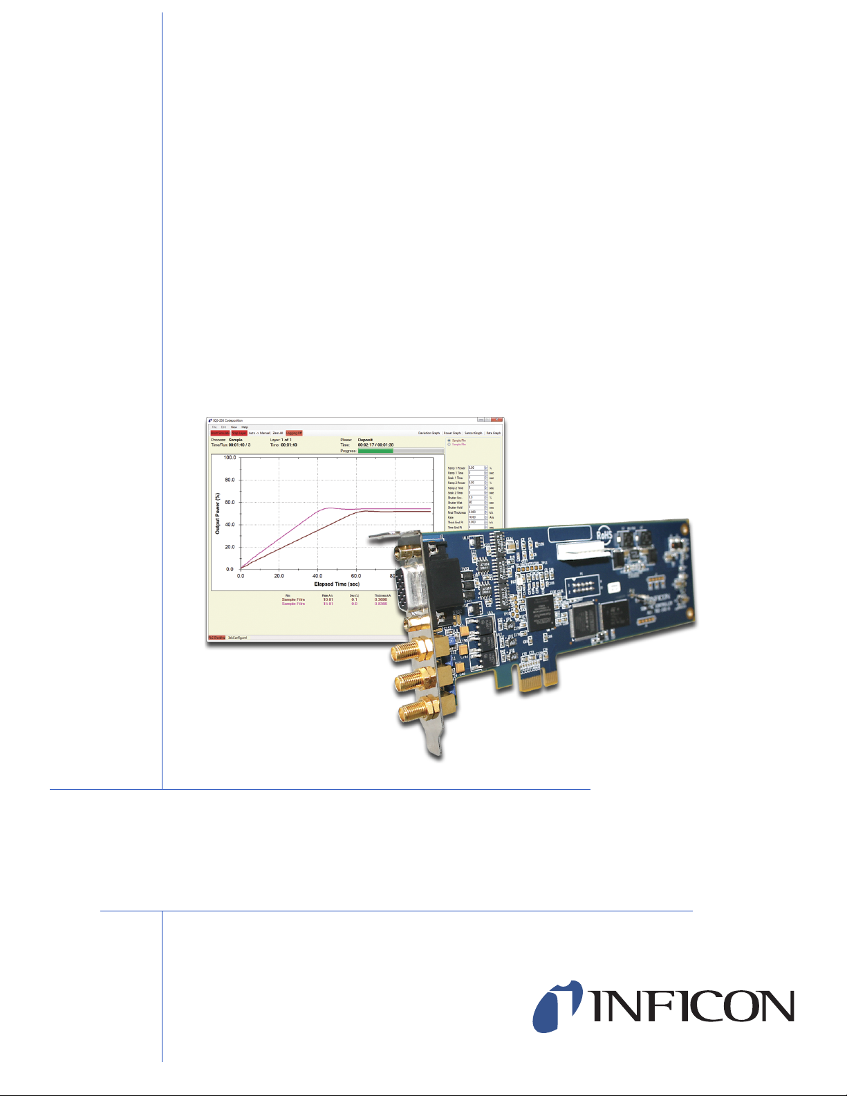
1.1 Introduction
IQS-233 Codeposition software works with INFICON IQM-233 or SQM-242 cards
to provide a powerful, Windows computer-based, thin film deposition controller.
See Figure 1-1.
Figure 1-1 IQS-233 Codeposition software display
IQS-233 Operating Manual
Chapter 1
Introduction
IPN 074-585-P1A
1 - 1
Page 12

IQS-233 Operating Manual
1.1.1 IQS-233 Codeposition Software Features
Supports up to two IQM-233 cards
Measures up to six quartz crystal sensors simultaneously
Controls up to six deposition source power supplies simultaneously for
codeposition.
Supports up to two SQM-242 cards (SAM-242 card not supported)
Measures up to eight quartz crystal sensors simultaneously
Controls up to four deposition source power supplies simultaneously for
codeposition
Allows multi-layer processes
Provides preconditioning, multiple rate ramps, and feed/idle phases
Provides graphs of deposition rate, rate deviation, or power output
Stores process, film and material parameters.
Can be controlled remotely from another computer using the RS-232 or
Ethernet command protocol
Provides flexible and reliable digital I/O using an external Programmable Logic
Controller (PLC)
Easy PLC integration for event selectable relay commands and shutter
control
NOTE: PLC is not provided by INFICON.
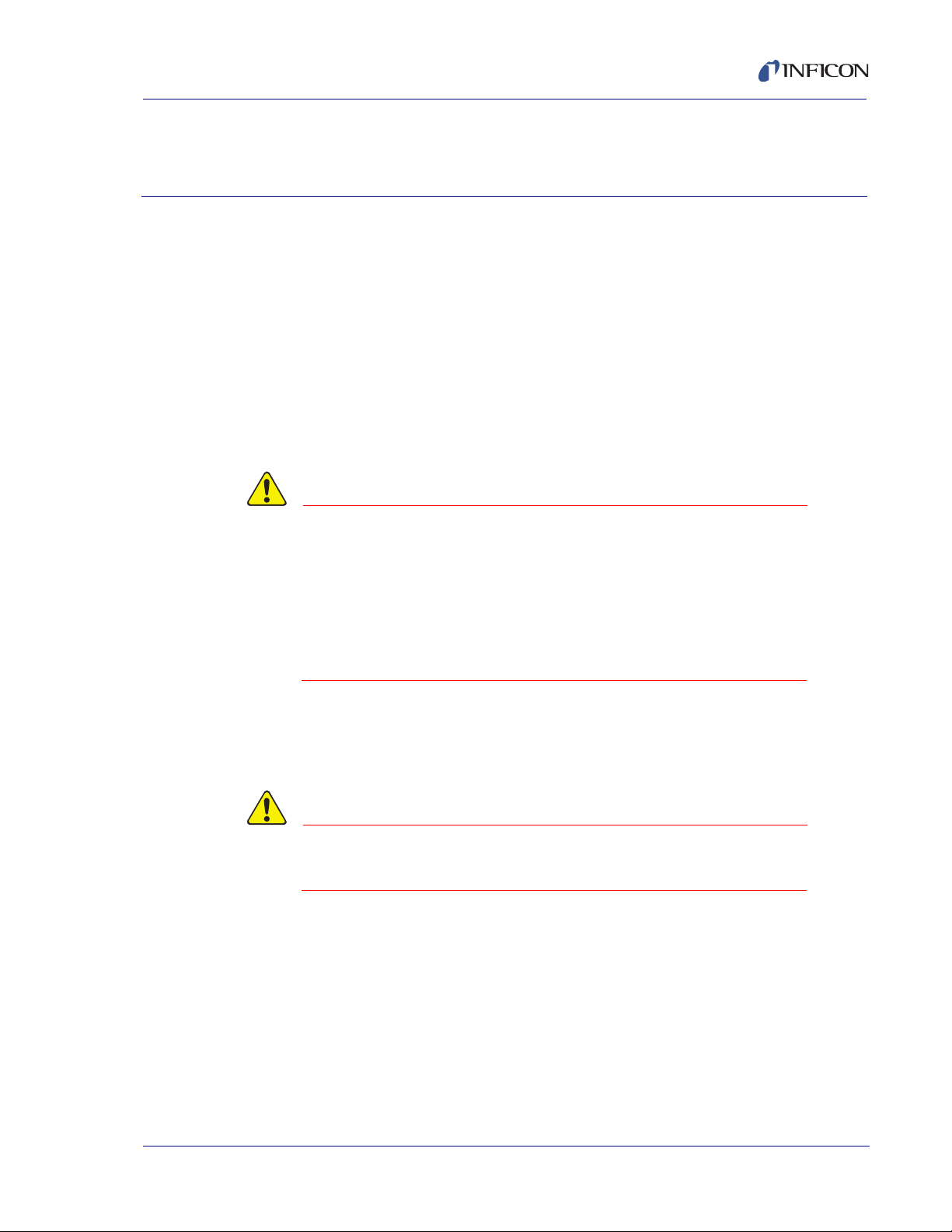
1.1.2 Hardware Supported by IQS-233 Codeposition Software
IQS-233 Codeposition software supports IQM-233 or SQM-242 cards (see
Figure 1-2 and Figure 1-3). Up to two IQM-233 or up to two SQM-242 cards can be
installed in the same computer with IQS-233 Codeposition software.
NOTE: If IQM-233 and SQM-242 cards are installed in the same computer,
IQS-233 Codeposition software will automatically select IQM-233 card(s)
and ignore SQM-242 card(s).
Refer to the IQM-233 or SQM-242 operating manuals for detailed information on
installing and using IQM-233 and SQM-242 cards.
IPN 074-585-P1A
1 - 2
Page 13
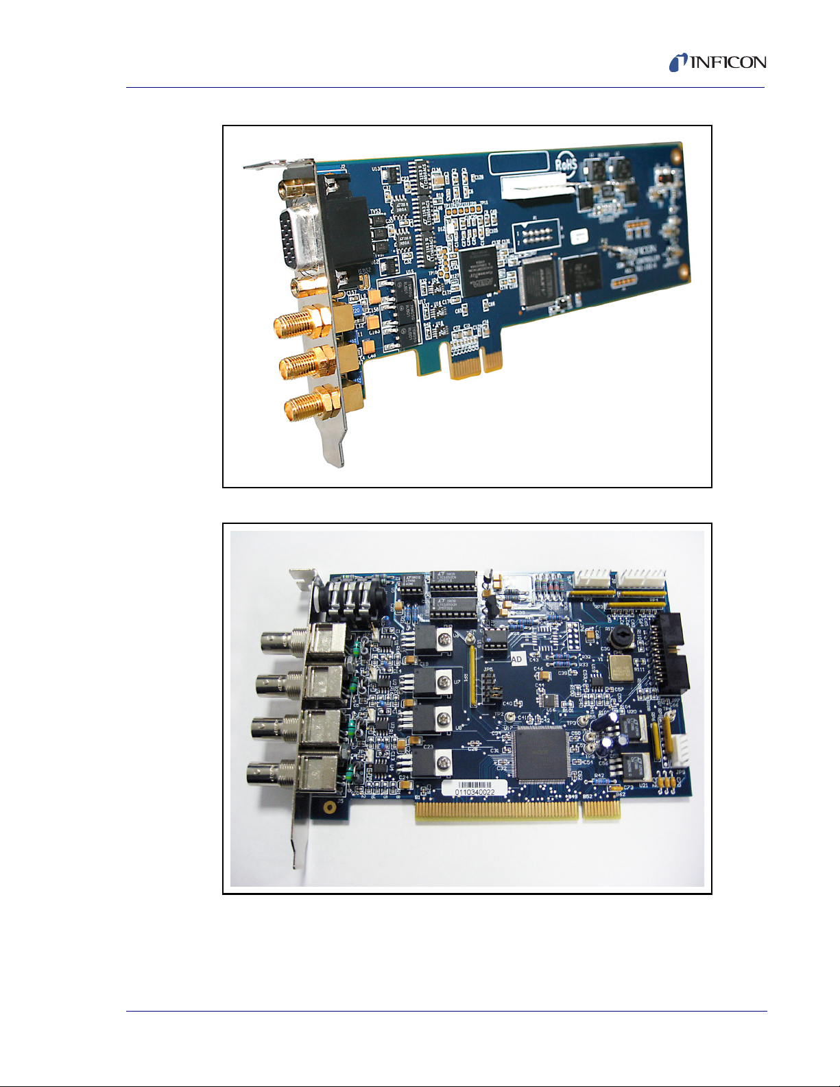
Figure 1-2 IQM-233 card
IQS-233 Operating Manual
Figure 1-3 SQM-242 card
IPN 074-585-P1A
1 - 3
Page 14

IQS-233 Operating Manual
1.1.2.1 Digital I/O Capability
IQM-233 and SQM-242 cards do not provide the digital inputs and outputs needed
to automatically control source and sensor shutters, rotate source pockets, etc.
However, digital I/O capability can be added by interfacing an external,
Programmable Logic Controller (PLC) with IQS-233 Codeposition software. The
PLC is not provided by INFICON. See Chapter 3, Digital I/O.
1.1.3 Computer Requirements
Processor . . . . . . . . . . . . . . . . . . . . . 1.5 GHz CPU minimum
RAM . . . . . . . . . . . . . . . . . . . . . . . . . 2 GB RAM minimum
Memory . . . . . . . . . . . . . . . . . . . . . . 200 MB hard disk space minimum
Operating System . . . . . . . . . . . . . . Windows XP SP3, Windows 7 32/64-bit,
Screen Resolution . . . . . . . . . . . . . . 800 x 600 minimum
Case (IQM-233 Card). . . . . . . . . . . . Standard or Small Form Factor
Windows 8 32/64-bit
Case (SQM-242 Card) . . . . . . . . . . . Standard
Bus Interface (IQM-233 Card) . . . . . PCI Express x1, x4, x8, x16
Bus Interface (SQM-242 Card) . . . . PCI
Communication Interface . . . . . . . . . RS-232C when interfacing an external PLC
RS-232C Baud Rate . . . . . . . . . . . . 4800, 9600, 19200, 38400, 57600, 115200
1.1.4 Related Operating Manuals
Operating manuals can be downloaded from www.inficon.com
074-584 . . . . . . . . . . . . . . . . . . . . . . IQM-233 Operating Manual
074-549 . . . . . . . . . . . . . . . . . . . . . . SQM-242 Operating Manual
IPN 074-585-P1A
1 - 4
Page 15

1.2 How To Contact INFICON
Worldwide customer support information is available under Contact >> Support
Worldwide at www.inficon.com:
Sales and Customer Service
Technical Support
Repair Service
If you are experiencing a problem with your IQS-233 Codeposition software,
please have the following information readily available:
The Sales Order or PO number of the software purchase.
The version of IQS-233 Codeposition software. See Figure 2-54 on page 2-72.
The version of Windows operating system.
A description of the problem.
An explanation of any corrective action that you may have already attempted.
The exact wording of any error messages that you may have received.
IQS-233 Operating Manual
1.3 Software Specifications
1.3.1 Display
Graphs . . . . . . . . . . . . . . . . . Rate, Deviation (Rate %), Power (%), Sensors
(Rate)
Readouts . . . . . . . . . . . . . . . Rate Å/s, Dev (%), Thickness kÅ, Power (%),
Frequency (MHz), Life (%), Process name, Film
name, Layer number, Phase, Process Time,
Layer Time, Phase Time
1.3.2 Process Parameters
IPN 074-585-P1A
Processes. . . . . . . . . . . . . . . Unlimited number of processes
Process Name . . . . . . . . . . . 15 characters maximum
Sensors . . . . . . . . . . . . . . . . IQM-233: 1 to 6 (1 to 3 Dual)
SQM-242: 1 to 8 (1 to 4 Dual)
Outputs. . . . . . . . . . . . . . . . . IQM-233: 1 to 6
SQM-242: 1 to 4
Layers. . . . . . . . . . . . . . . . . . Unlimited number of layers
Film. . . . . . . . . . . . . . . . . . . . Any defined film
Outputs. . . . . . . . . . . . . . . . . IQM-233: 1 to 6
SQM-242: 1 to 4
1 - 5
Page 16

IQS-233 Operating Manual
Input . . . . . . . . . . . . . . . . . . . Sensor(s), Timed Power
Setpoint Å/s . . . . . . . . . . . . . -999.90 to 999.90 Å/s
Setpoint % Pwr. . . . . . . . . . . 0.00 to 100.00% Power
Final Thickness . . . . . . . . . . 0.000 to 999.900 kÅ
Thickness Endpoint . . . . . . . 0.000 to 999.900 kÅ
Time Endpoint . . . . . . . . . . . 0.00 to 30000.00 s
Start Mode . . . . . . . . . . . . . . Manual Start, Auto Start, Skip Pre Cond
Source Indexers . . . . . . . . . . IQM-233: 6
SQM-242: 4
Index Pockets. . . . . . . . . . . . 0 to 15
Timeout . . . . . . . . . . . . . . . . 0 to 3000 s
Substrate Indexer. . . . . . . . . 1
Index Pockets. . . . . . . . . . . . 0 to 4
Timeout . . . . . . . . . . . . . . . . 0 to 3000 s
User Indexers. . . . . . . . . . . . 2
Index Pockets. . . . . . . . . . . . 0 to 15
Timeout . . . . . . . . . . . . . . . . 0 to 3000 s
Rate Ramps . . . . . . . . . . . . . Unlimited number of Rate Ramps
Start Thickness. . . . . . . . . . . 0.000 to 999.900 kÅ
Ramp Time. . . . . . . . . . . . . . 0.00 to 30000 s
Setpoint Å/s . . . . . . . . . . . . . -999.90 to 999.90 Å/s
Setpoint % Pwr. . . . . . . . . . . 0.00 to 100.00% Power
1.3.3 Film Parameters
Films. . . . . . . . . . . . . . . . . . . Unlimited number of films
Film Name . . . . . . . . . . . . . . 15 characters maximum
P Term . . . . . . . . . . . . . . . . . 0 to 9999
I Term . . . . . . . . . . . . . . . . . . 0.0 to 999.9 s
D Term . . . . . . . . . . . . . . . . . 0.00 to 99.90 s
IPN 074-585-P1A
1 - 6
Shutter Delay Accuracy . . . . 0.0 to 30.0%
Shutter Delay Wait . . . . . . . . 0.00 to 30000 s
Shutter Delay Hold . . . . . . . . 0.00 to 30000 s
Page 17

IQS-233 Operating Manual
Rate Sampling . . . . . . . . . . . Continuous, Accuracy Based, Time Based
Accuracy Based . . . . . . . . . . 0.00 to 100.00%
Time Based Sample . . . . . . . 0.00 to 100.00 s
Time Based Hold . . . . . . . . . 0.00 to 100.00 s
Ramp (1, 2) Power . . . . . . . . 0.00 to 100.00%
Ramp (1, 2) Time . . . . . . . . . 0.00 to 30000 s
Soak (1, 2) Time. . . . . . . . . . 0.00 to 30000 s
Feed Power . . . . . . . . . . . . . 0.00 to 100.0%
Feed Ramp Time . . . . . . . . . 0.00 to 100 s
Feed Time . . . . . . . . . . . . . . 0.00 to 100 s
Idle Power . . . . . . . . . . . . . . 0.00 to 100.0%
Idle Ramp Time . . . . . . . . . . 0.00 to 100 s
Material. . . . . . . . . . . . . . . . . Any defined material
Max Power . . . . . . . . . . . . . . 0.00 to 100.00%
Slew Rate . . . . . . . . . . . . . . . 0.0 to 100.0%
Sensor Tooling . . . . . . . . . . . IQM-233: 1 to 6, 0.0 to 999.0%
SQM-242: 1 to 8, 0.0 to 999.0%
On Error . . . . . . . . . . . . . . . . Ignore, Stop Layer, Timer Power
Control Error %. . . . . . . . . . . 0 to 30%
Control Error sec . . . . . . . . . 0 to 99 s
Crystal Fail Counts . . . . . . . . 0 to 99
Crystal Quality % . . . . . . . . . 0 to 50%
Crystal Quality Counts . . . . . 0 to 99
IPN 074-585-P1A
Crystal Stability Single . . . . . 25 to 9999 Hz
Crystal Stability Total . . . . . . 25 to 9999 Hz
1.3.4 Material Parameters
Name . . . . . . . . . . . . . . . . . . 24 characters maximum
Density . . . . . . . . . . . . . . . . . 0.40 to 99.99 g/cm
3
Z-Factor . . . . . . . . . . . . . . . . 0.100 to 9.999
1 - 7
Page 18

IQS-233 Operating Manual
1.3.5 System Parameters
Outputs. . . . . . . . . . . . . . . . . IQM-233: 1 to 6
Full Scale Out. . . . . . . . . . . . -10.0 to 10.0 V (dc)
Sensors . . . . . . . . . . . . . . . . IQM-233: 1 to 6 (1 to 3 Dual)
Control . . . . . . . . . . . . . . . . . Rate, Thickness
Relays (PLC required) . . . . . 16
Relay Events . . . . . . . . . . . . Source Shutter (1 to 6), Source Active (1 to 6),
Inputs (PLC required). . . . . . 12
SQM-242: 1 to 4
SQM-242: 1 to 8 (1 to 4 Dual)
Sensor Shutter (1 to 8), Process Stopped, Process
Running, Layer Stopped, Layer Running, Deposit
Phase, Pre-Cond Phase, Soak Hold Phase, Process
Active, Manual Mode, Max Power, Time Setpoint,
Thickness Setpoint, Final Thickness, All Crystals
Good, All Crystals Fail
Input Events . . . . . . . . . . . . . Start Process, Abort Process, Start Layer, Stop
Layer, Next Layer, Force Final Thickness, Zero
Thickness, Zero Time (NA), Soak 2 Hold, Soak 2
Release
Card Type. . . . . . . . . . . . . . . IQM-233, SQM-242
Period. . . . . . . . . . . . . . . . . . 0.10, 0.25, 0.50, 1.00, 2.00 s
Maximum Frequency . . . . . . 4.002000 to 6.100000 MHz
Initial Frequency. . . . . . . . . . 4.001000 to 6.099000 MHz
Minimum Frequency. . . . . . . 4.000000 to 6.098000 MHz
Computer Interface . . . . . . . RS-232, Ethernet, Windows Communication
Foundation
RS-232 Baud . . . . . . . . . . . . 4800, 9600, 19200, 38400, 57600, 115200
Filter Readings . . . . . . . . . . . 1, 2, 3, 4, 5, 6, 7, 8, 9, 10
Last Output Displayed . . . . . 1 to 6
Units . . . . . . . . . . . . . . . . . . . Thickness, Mass
Graph X Axis Width . . . . . . . 0 to 100
IPN 074-585-P1A
1 - 8
Graph Y Axis Height. . . . . . . 0 to 10000
Page 19

1.3.6 Security
User Name . . . . . . . . . . . . . . 10 characters maximum
Password . . . . . . . . . . . . . . . 10 characters maximum
Access Levels . . . . . . . . . . . 3
IQS-233 Operating Manual
IPN 074-585-P1A
1 - 9
Page 20

IQS-233 Operating Manual
This page is intentionally blank.
1 - 10
IPN 074-585-P1A
Page 21
IQS-233 Operating Manual
CAUTION
CAUTION
IQS-233 Codeposition Software
2.1 Introduction
This chapter covers the installation and operation of IQS-233 Codeposition
software. Refer to the IQM-233 or SQM-242 operating manual for installation
instructions of an IQM-233 card or SQM-242 card.
2.2 Installing IQS-233 Codeposition Software
IQS-233 Codeposition software supports up to two IQM-233 cards or up to two
SQM-242 cards.
If IQM-233 and SQM-242 cards are installed together in
the same computer, IQS-233 Codeposition software will
communicate with up to two IQM-233 cards and ignore
the SQM-242 card(s).
Chapter 2
IQM-233 card(s) must be removed to use
IQS-233 Codeposition software with SQM-242 card(s).
The required Dynamic Link Library (DLL), device driver, and WinDriver are installed
by the IQM233 DLL or the SQM242 with IQM DLL setup file. To install the DLL,
device driver, and WinDriver, see section 2.2.1.
IPN 074-585-P1A
NOTE: IQS-233 Codeposition software and the IQM233 DLL or SQM242 with
IQM233 DLL and SQM242 with IQM DLL cannot be
installed together on the same computer.
IQM DLL may be installed before or after the installation of the IQM-233 or
SQM-242 card(s). Refer to the IQM-233 or SQM-242 operating manual for
card installation instructions.
2 - 1
Page 22

IQS-233 Operating Manual
2.2.1 Installing the DLL, Device Driver, and WinDriver
1 If the operating system is Windows 7 or 8, click Start >> Control Panel >>
System. Note the operating system size (32-bit or 64-bit) displayed under
System type.
If the operating system is Windows XP, click Start >> Settings >> Control
Panel >> System >> System Properties >> General tab. Determine the
operating system size from the operating system name displayed under
System:
Windows XP Home, Windows XP Media Center Edition, and Windows XP
Professional are 32-bit operating systems.
Windows XP Professional x64 Edition is a 64-bit operating system.
NOTE: The operating system size will generally match the performance
capabilities of the computer processor. However, it is possible to have
a 64-bit processor and a 32-bit operating system. In this case, the
64-bit installation is required.
2 Insert the IQS-233 Codeposition Operating Manual CD into the computer’s
CD drive.
3 Click Windows Explorer or File Explorer >> Computer >> (CD drive letter:)
IQS-233 >> IQM-233 Drivers.
4 If IQS-233 Codeposition software is to be used with an IQM-233 card:
For a 32-bit operating system, double-click
IQM233 DLL x86 v x.x.x.x Setup.exe
For a 64-bit operating system, double-click
IQM233 DLL x64 v x.x.x.x Setup.exe
If IQS-233 Codeposition software is to be used with an SQM-242 card:
For a 32-bit operating system, double-click
SQM242 with IQM DLL x86 v x.x.x.x Setup.exe
For a 64-bit operating system, double-click
SQM242 with IQM DLL x64 v x.x.x.x Setup.exe
IPN 074-585-P1A
2 - 2
Page 23
IQS-233 Operating Manual
CAUTION
IQM233 DLL and SQM242 DLL can be installed in the
same computer.
However, when IQM-233 and SQM-242 cards are installed
in the same computer, IQS-233 Codeposition software
will interface only with IQM-233 card(s) and ignore the
SQM-242 card(s).
IQM-233 card(s) must be removed for
IQS-233 Codeposition software to communicate with
SQM-242 card(s).
5 The InstallShield Wizard window will display.
6 Click Next.
7 Read the license agreement.
8 If it is acceptable, click I accept the terms in the license agreement.
9 Click Next.
10 Type the requested information into the User Name and Organization boxes.
11 Click Next.
12 Click Install to start the installation of the device driver and the DLL.
13 When Install Wizard Completed is displayed, click Finish to close the
InstallShield Wizard.
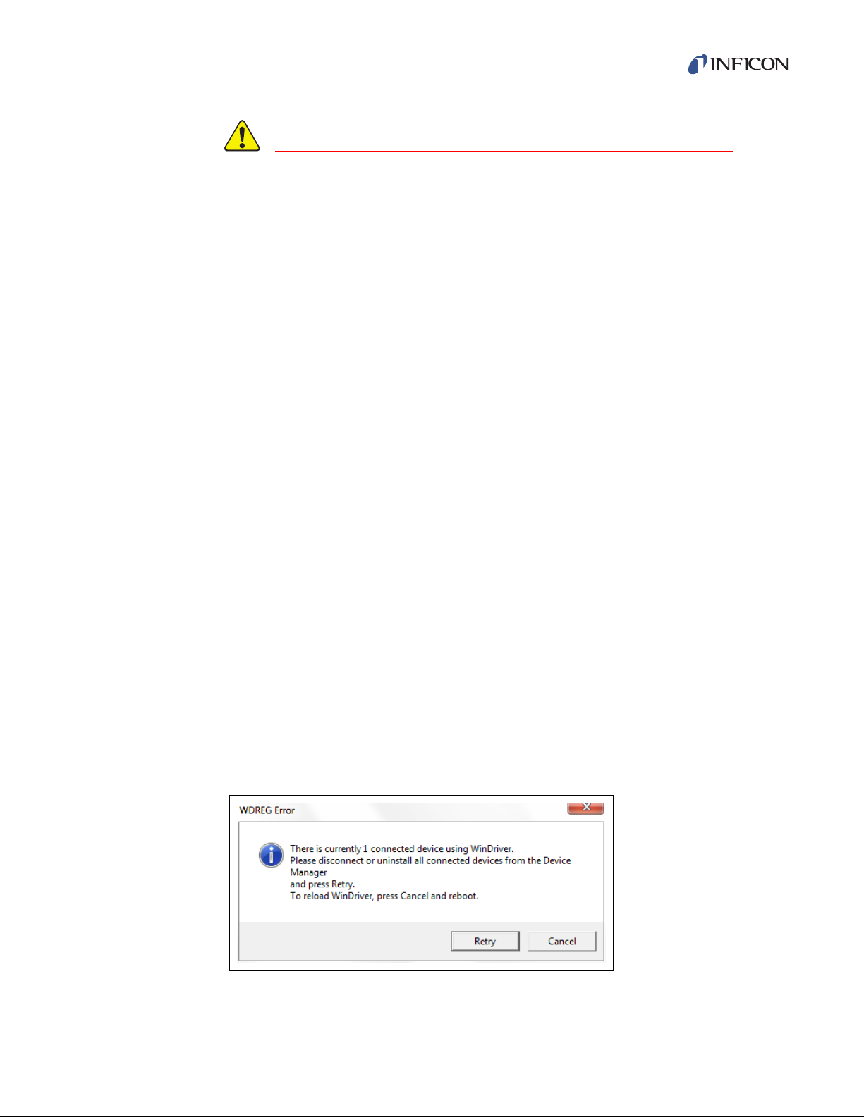
2.2.1.1 Troubleshooting the DLL Installation
If the WDREG Error window appears (see Figure 2-1), an existing version of
IPN 074-585-P1A
WinDriver is preventing the installation of the DLL.
Figure 2-1 WDREG Error
2 - 3
Page 24
IQS-233 Operating Manual
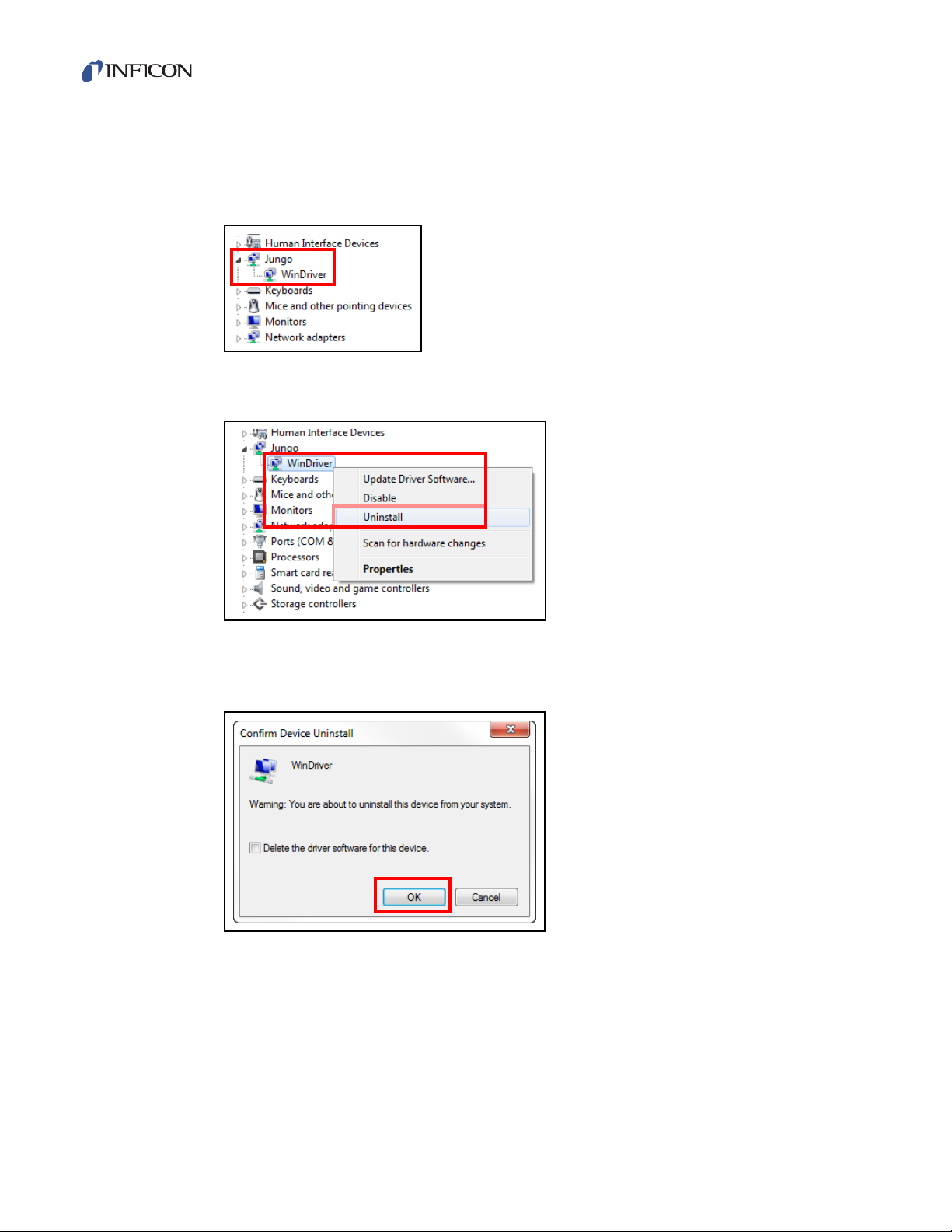
To remove the existing WinDriver and install the required WinDriver:
1 In Windows Device Manager, click the expansion button () next to Jungo to
display WinDriver. See Figure 2-2.
Figure 2-2 Jungo and WinDriver
2 Right-click WinDriver and click Uninstall. See Figure 2-3.
Figure 2-3 Uninstall WinDriver
3 When the Confirm Device Uninstall window appears, click OK to uninstall
WinDriver. See Figure 2-4.
Figure 2-4 Confirm Device Uninstall
4 In the WDREG Error window, click Retry to continue with the DLL installation.
Refer to Figure 2-1.
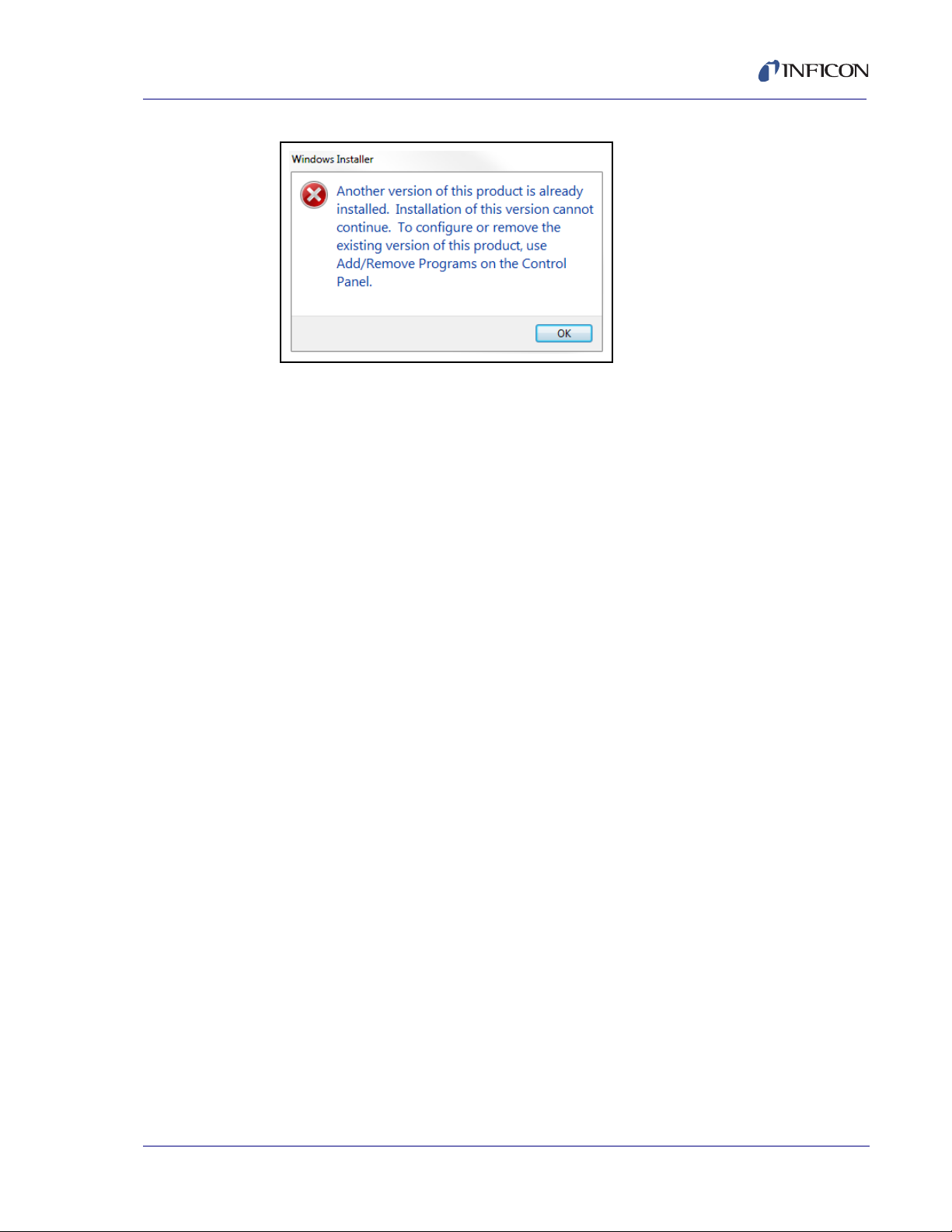
If the Windows Installer window appears (see Figure 2-5), another DLL
(IQM233 DLL or SQM242 with IQM DLL) is already installed. IQM233 DLL
and SQM242 with IQM DLL cannot be installed together on the same
computer.
IPN 074-585-P1A
2 - 4
Page 25
IQS-233 Operating Manual
Figure 2-5 Windows Installer window
4a Click OK to keep the previously installed DLL, or
4b To remove the previously installed DLL and install a different DLL:
4b1 Click OK to close the Windows Installer window.
4b2 Click Control Panel >> Programs to display a list of installed
programs.
4b3 Select the IQM233 DLL or the SQM242 with IQM DLL from the list.
4b4 Click Uninstall to remove the selected DLL.
4b5 Install the DLL again. Refer to section 2.2.1 on page 2-2.
IPN 074-585-P1A
2 - 5
Page 26

IQS-233 Operating Manual
2.2.2 Installing IQS-233 Codeposition Software
NOTE: To update an existing installation of IQS-233 Codeposition software to a
newer version, see section 2.2.3.
1 Click Windows Explorer or
File Explorer >> Computer >> (CD drive letter:) IQS-233.
2 Double-click IQS-233 SETUP.EXE.
3 The InstallShield Wizard will display.
4 Click Next.
5 Read the license agreement.
6 If it is acceptable, click I accept the terms in the license agreement.
7 Click Next.
8 Type the requested information into the User Name and Organization boxes.
9 Click Next.
10 Click Install to start the software installation.
11 When Install Wizard Completed is displayed, click Finish to close the
InstallShield Wizard window.
2.2.3 Updating IQS-233 Codeposition Software
To update an existing installation of IQS-233 Codeposition software to a newer
version:
1 Click Control Panel >> Programs.
2 If the IQS-233 Codeposition software was used with an IQM-233 card, select
IQM233 DLL x86 or IQM233 DLL x64.
If the IQS-233 Codeposition software was used with an SQM-242 card, select
SQM242 with IQM DLL x86 or SQM242 with IQM 233 DLL x64.
3 Click Uninstall to remove IQM233 DLL or SQM242 with IQM DLL.
4 In Programs, select IQS-233 Codeposition.
5 Click Uninstall to remove the previous version of IQS-233 Codeposition
software.
6 Install the latest version of IQM233 DLL or SQM242 with IQM DLL, as
appropriate. Refer to section 2.2.1 on page 2-2.
IPN 074-585-P1A
2 - 6
7 Install the latest version of IQS-233 Codeposition software. Refer to section
2.2.2.
Page 27
IQS-233 Operating Manual
2.3 Using IQS-233 Codeposition Software
2.3.1 Starting IQS-233 Codeposition Software
2.3.1.1 Starting the Software in Windows XP or Windows 7
1 Click Start >> All Programs >> INFICON >> IQS-233 Codeposition.
2 The User Login window will display. See Figure 2-6.
2.3.1.2 Starting the Software in Windows 8
1 In the Start window, click the IQS-233 Codeposition icon.
2 If the icon cannot be found:
2a Click Search >> Apps.
2b Type IQS-233 in the Search text box.
2c Click the IQS-233 Codeposition icon.
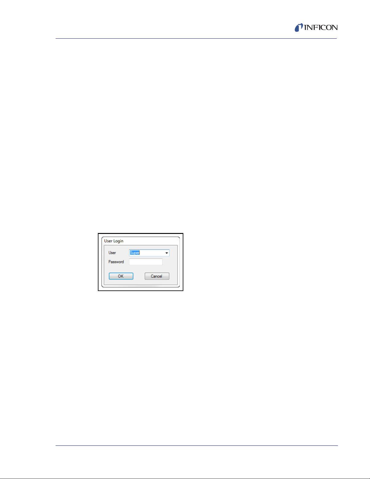
2.3.2 Logging On to the Software
On the initial login, the User Login window will display Super as the default User
name. See Figure 2-6.
Figure 2-6 User Login window
A Password is not required to log on to a user session with the default User name.
Click OK to close the User Login window and display the IQS-233 Codeposition
window. See Figure 2-7.
IPN 074-585-P1A
NOTE: If security settings are changed from the default values, a different User
name and Password may be required. See section 2.3.3.7 on page 2-61.
2 - 7
Page 28
IQS-233 Operating Manual
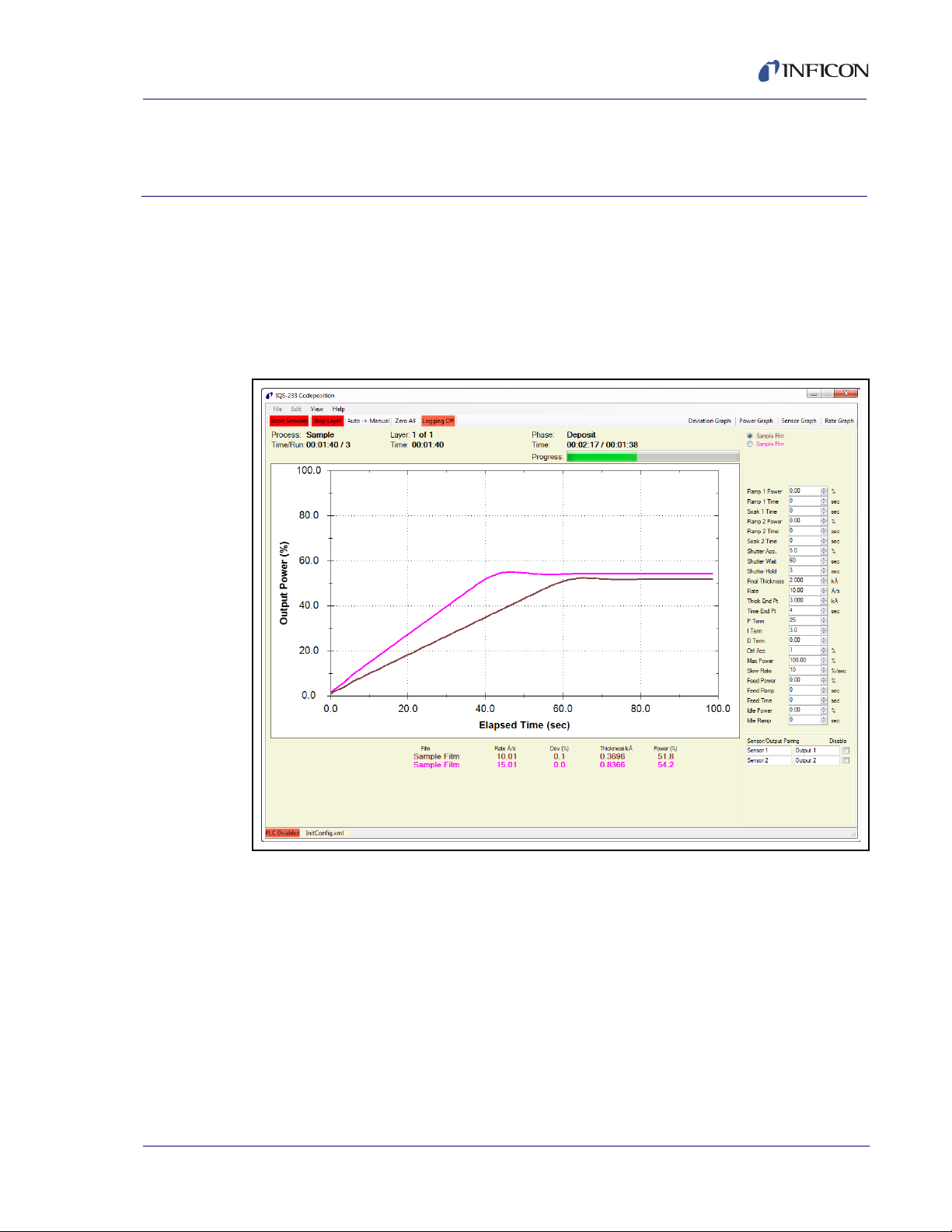
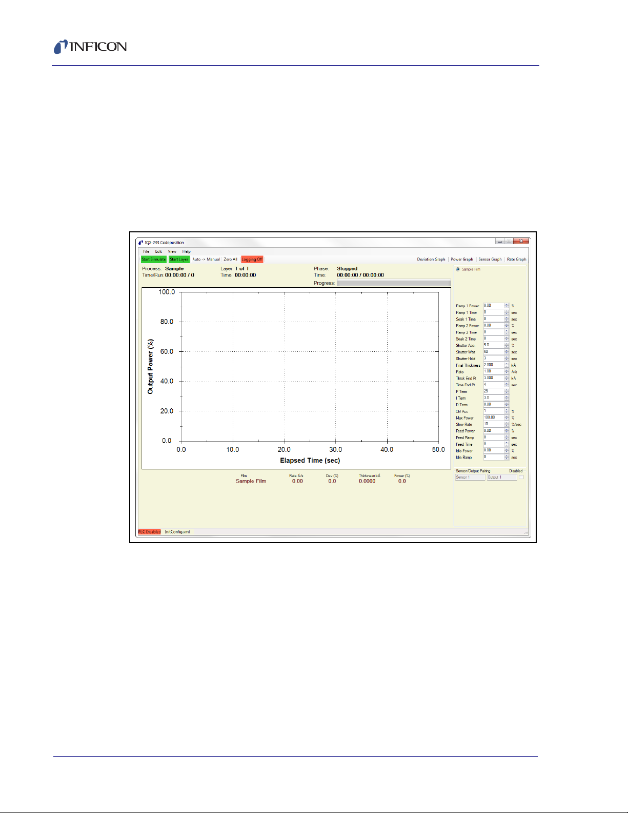
2.3.3 IQS-233 Codeposition Window
The IQS-233 Codeposition window displays readouts for Film, Rate, Deviation,
Thickness and Power simultaneously for each active output. This window also
provides Process, Layer, Phase, Run, and Time for each active output as well as
customizable process parameters, graphical information, and access to File, Edit,
View, and Help menus. See Figure 2-7.
NOTE: The Rate, Deviation, and Thickness readings displayed represent an
average of the sensors assigned to each film.
Figure 2-7 IQS-233 Codeposition window
2 - 8
NOTE: To zoom in the graph pane, click in the graph pane on the IQS-233
Codeposition window and drag to draw a box over the data needing to be
enlarged. To further zoom in, or to zoom out, rotate the wheel button up or
down, respectively, with the pointer in the graph pane.
File, see section 2.3.3.1
Edit, see section 2.3.3.5 on page 2-17
View, see section 2.3.4.1 on page 2-66
Help, see section 2.3.5.1 on page 2-73
IPN 074-585-P1A
Page 29
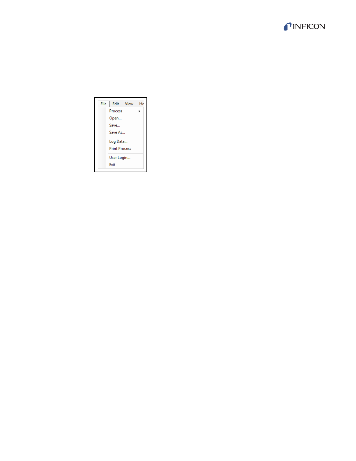
2.3.3.1 File
IQS-233 Operating Manual
Click File to display the list of File commands. See Figure 2-8.
NOTE: File commands are not available once a process is started or while a
process is running.
Figure 2-8 File commands
Process, see section 2.3.3.1.1
Open, see section 2.3.3.1.2 on page 2-11
Save, see section 2.3.3.1.3 on page 2-12
Save As, see section 2.3.3.1.4 on page 2-12
Log Data, see section 2.3.3.1.5 on page 2-14
Print Process, see section 2.3.3.2 on page 2-16
User Login, see section 2.3.3.3 on page 2-16
Exit, see section 2.3.3.4 on page 2-17
IPN 074-585-P1A
2 - 9
Page 30
IQS-233 Operating Manual
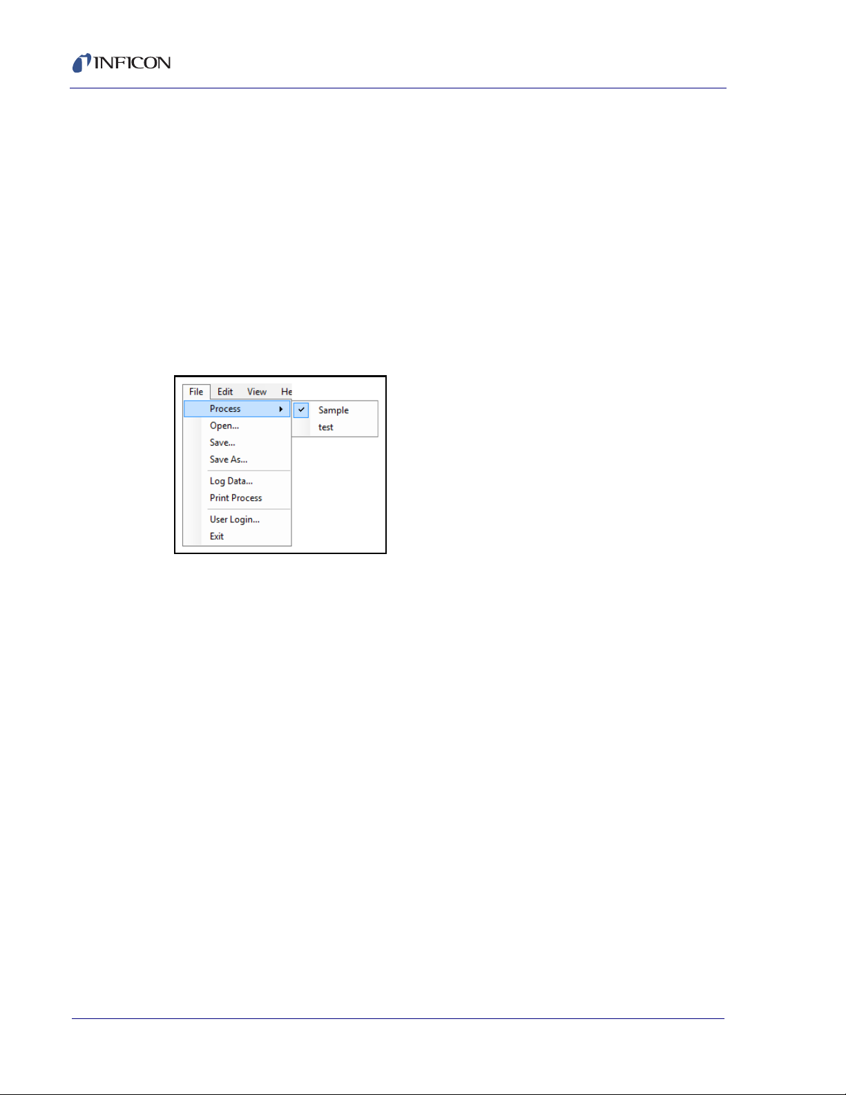
2.3.3.1.1 Process
Click File >> Process to display a list of saved process configurations (see Figure
2-9). A check mark next to the current process name indicates that the process
configuration has been loaded for that process name.
NOTE: The current process name is also displayed in the IQS-233 Codeposition
The process configuration consists of all of the parameters in the Process window
(see Figure 2-16 on page 2-18). System and security parameters are not included
in the process configuration. System parameters are contained in the .xml
configuration file. A different set of system parameters can be selected by loading
a previously saved configuration file (see section 2.3.3.1.2).
Figure 2-9 Process list
window (refer to Figure 2-7 on page 2-8).
2 - 10
IPN 074-585-P1A
Page 31

2.3.3.1.2 Open
CAUTION
IQS-233 Operating Manual
Click File >> Open to display the Load Configuration window (see Figure 2-10)
where a previously saved configuration file containing a set of parameters used for
a previous deposition can be selected and loaded.
Configuration files are in .xml format. InitConfig.xml is loaded when
IQS-233 Codeposition software is started. Once the software is running, a different
configuration file can be selected and loaded. Another process can be selected
without altering the system parameters loaded by the configuration file (refer to
section 2.3.3.1.1).
Figure 2-10 Load Configuration window
IPN 074-585-P1A
Do not delete or alter the InitConfig.xml, Materials.xml,
Setup.xml, or Users.xml files located in the
C:\ProgramData\INFICON\IQS-233 Codeposition folder.
Do not move these files to another folder.
2 - 11
Page 32

2.3.3.1.3 Save
CAUTION
Click File >> Save to save the current Process and System parameter values to
the configuration filename displayed in the message pane on the
IQS-233 Codeposition window.
If the default configuration filename, InitConfig.xml, is displayed, the default
parameters loaded when IQS-233 Codeposition software is started will be
overwritten by any changes made to the Process and System parameters.
2.3.3.1.4 Save As
Click File >> Save As to save the current Process and System configuration under
a different name. Configuration files are saved in .xml format. The default folder for
saving a configuration file is C:\ProgramData\INFICON\IQS-233 Codeposition;
however, the configuration file may be saved to another folder location if desired
(see Figure 2-11).
IQS-233 Operating Manual
Do not delete or alter the InitConfig.xml, Materials.xml,
Setup.xml, and Users.xml files located in the
C:\ProgramData\INFICON\IQS-233 Codeposition folder.
Do not move these files to another folder.
IPN 074-585-P1A
2 - 12
Page 33

Figure 2-11 Save Configuration window
IQS-233 Operating Manual
IPN 074-585-P1A
2 - 13
Page 34

IQS-233 Operating Manual
2.3.3.1.5 Log Data
Click File >> Log Data to display the DataLog window where data log preferences
can be configured and saved to a .csv format data log file (see Figure 2-12).
Figure 2-12 DataLog window
When data logging is activated, data is recorded for the following parameters:
Process Name
Run Number
Date Time
Event
Layer
Process Time
Layer Time
Deposit Time
Output Number
Film
Thickness
Rate
Rate Deviation
Power
Sensor Number
Sensor Rate
Sensor Thickness
Frequency
IPN 074-585-P1A
2 - 14
NOTE: The parameters recorded in the data log file depend on the parameter
selections in the Events to Log pane of the DataLog window.
Page 35

IQS-233 Operating Manual
Log File pane
None . . . . . . . . . . . . . . . . . . . . . . . . Data logging is unavailable.
Filename . . . . . . . . . . . . . . . . . . . . . Displays the name of the file to which
process data will be saved.
Overwrite. . . . . . . . . . . . . . . . . . . . . Each process run is saved to the file name
displayed in the Filename box.
NOTE: Subsequent process runs will
overwrite previous data in this file.
Append . . . . . . . . . . . . . . . . . . . . . . Data logged for the current process run is
added on to the end of any previously logged
data in the file displayed in the Filename box.
Run # . . . . . . . . . . . . . . . . . . . . . . . . Each process run is saved as a separate file
with the format filename_#.csv, where # is a
number that increments with each new run.
Save As . . . . . . . . . . . . . . . . . . . . . . Displays the Save As window, where process
data can be saved as a .csv format file. The
name of this file will be displayed in the
Filename box.
View . . . . . . . . . . . . . . . . . . . . . . . . . Displays the default Log folder where data
log files are stored. Click a data log file to
display a preview of the file contents or
double-click the file to open it in Microsoft®
®
Excel
IPN 074-585-P1A
.
2 - 15
Page 36

IQS-233 Operating Manual
Events to Log pane
End Deposit Phase. . . . . . . . . . . . . Data is recorded at the end of each layer’s
deposit phase.
End Each Phase . . . . . . . . . . . . . . . Data is recorded at the end of all phases.
I/O Events . . . . . . . . . . . . . . . . . . . . Data is recorded each time an external digital
input or output changes state.
Timed. . . . . . . . . . . . . . . . . . . . . . . . Data is recorded at the selected time interval.
Sensors . . . . . . . . . . . . . . . . . . . . . . Data is recorded for individual sensors in
addition to the normally recorded data.
Readings (yymmdd.log) . . . . . . . . When the Readings check box is selected,
the following data from individual sensors is
recorded and saved in a separate file: Timer,
Run Time, Sensor #, Rate, Thickness, and
Frequency. The file is saved in the format of
yymmdd.csv (for example, data saved on
January 15, 2014 will be saved to a file
named 140115.csv).
2.3.3.2 Print Process
Click File >> Print Process to print the configuration parameters for the current
Process to the default printer.
2.3.3.3 User Login
Click File >> User Login to display the User Login window (see Figure 2-13)
allowing a different user to log on to IQS-233 Codepostion software. When a
different User name and its associated Password are entered, the current session
is ended and the security access levels change to that of the new user. See
section 2.3.3.7 on page 2-61 for more information.
Figure 2-13 User Login window
IPN 074-585-P1A
2 - 16
Page 37

2.3.3.4 Exit
2.3.3.5 Edit
IQS-233 Operating Manual
Click File >> Exit to display the Exit window (see Figure 2-14). When exiting the
software, changes made to the current Process, Film, and System parameters can
be saved to the configuration filename displayed in the Exit window by selecting
the Save any changes to (name).xml check box and clicking Yes. Refer to
section 2.3.3.1.4 on page 2-12 to save parameter changes to a different
configuration filename.
Figure 2-14 Exit window
Click Edit to display the list of Edit commands. See Figure 2-15.
NOTE: The Edit commands are not available once a process is started or while a
process is running.
Figure 2-15 Edit items list
Process, see section 2.3.3.5.1
IPN 074-585-P1A
Films, see section 2.3.3.5.6 on page 2-28
Materials, see section 2.3.3.5.12 on page 2-42
System, see section 2.3.3.6 on page 2-44
Security, see section 2.3.3.7 on page 2-61
2 - 17
Page 38

2.3.3.5.1 Process
Click Edit >> Process to display the Process window. The Process window
provides the commands needed to develop a thin film deposition process
consisting of one or more Layers. See Figure 2-16.
Figure 2-16 Process window
IQS-233 Operating Manual
2 - 18
Process name and edit commands, see section 2.3.3.5.2
Layer tab, see section 2.3.3.5.4 on page 2-23
Rate Ramps tab, see section 2.3.3.5.5 on page 2-26
IPN 074-585-P1A
Page 39

2.3.3.5.2 Process Name and Edit Commands
Process Name
Process name box . . . . . . . Select a name from a list of previously saved
Process names to load the configuration for that
Process. See Figure 2-17.
Figure 2-17 Process window - Process name and edit commands
IQS-233 Operating Manual
IPN 074-585-P1A
Rename . . . . . . . . . . . . . . . Displays the Rename Process Name window where
the name of the current Process can be changed.
The original Process name is replaced. See
Figure 2-18.
Figure 2-18 Rename Process Name window
2 - 19
Page 40

IQS-233 Operating Manual
CAUTION
New . . . . . . . . . . . . . . . . . . . Displays the New Process Name window where the
name for a new Process configuration can be
entered. When the New Process Name window is
closed (by clicking OK), the name for the new
Process is displayed in the Process name box and
the default Process configuration is displayed. The
original Process name is not deleted. See
Figure 2-19.
Figure 2-19 New Process Name window
Delete . . . . . . . . . . . . . . . . . Deletes the current Process configuration from the
database of Process configurations.
Delete cannot be undone.
Copy . . . . . . . . . . . . . . . . . . Displays the Copy Selected Process to New Process
Name window where a duplicate of the current
Process configuration can be named and saved.
See Figure 2-20.
Figure 2-20 Copy Selected Process to New Process Name window
IPN 074-585-P1A
2 - 20
Page 41

2.3.3.5.3 Layer Information and Edit Commands
A Process consists of the Layer(s) displayed in the Layer information pane (see
Figure 2-21). A Layer consists of the parameters configured in the Layer tab (see
Figure 2-22 on page 2-23) and Rate Ramps tab (see Figure 2-23 on page 2-26).
Figure 2-21 Process window - Layer information and edit commands
IQS-233 Operating Manual
Layer . . . . . . . . . . . . . . . . . . Click the number of the desired Layer to display the
parameters in the Layer and Rate Ramps tabs
pertaining to that Layer.
NOTE: All related Codeposition Layers have the
IPN 074-585-P1A
same Layer number, but each Codeposition
Layer must use a different Output.
Out . . . . . . . . . . . . . . . . . . . The name of the source Output mapped to a
physical source output connection on the IQM-233
or SQM-242 card. Refer to the IQM-233 or SQM-242
operating manual for information about the source
output connection. The Output name is selected in
the Layer tab (see Figure 2-22 on page 2-23). The
relationship between the Output name and the
physical output connection on the IQM-233 or
SQM-242 card is configured in the Outputs tab of the
System Setup window (see Figure 2-37 on page
2-45).
2 - 21
Page 42

IQS-233 Operating Manual
Film . . . . . . . . . . . . . . . . . . . The Film name selected in the Layer tab.
Setpoint . . . . . . . . . . . . . . . The Setpoint value selected in the Layer tab.
Final Thickness . . . . . . . . . The Final Thickness value selected in the Layer tab.
Time Endpoint . . . . . . . . . . The Time Endpoint value selected in the Layer tab.
Cut Layer . . . . . . . . . . . . . . Deletes the selected Layer from the Layer
information pane and moves that Layer to the
Clipboard.
Copy Layer . . . . . . . . . . . . . Copies the selected Layer to the Clipboard.
Paste Layer . . . . . . . . . . . . Inserts a Layer from the Clipboard directly below the
selected Layer. The Layer number increments for
each new Layer. Any Layers below the selected
Layer are shifted downward and their Layer numbers
are incremented accordingly. Click Paste repeatedly
to insert multiple Layers. The parameters for the new
Layer(s) in the Layer and Rate Ramps tabs can then
be changed as needed.
Paste CoDep . . . . . . . . . . . Pastes a Layer from the Clipboard directly below a
selected Layer. The selected Layer and pasted
Layer will become Codeposition Layers with the
same Layer number. Any Layers below the pasted
Layer will be shifted downward and their Layer
numbers incremented accordingly.
To create Codeposition Layers
1 Click an existing Layer and click Copy Layer.
2 Change the Output in the Layer tab (see Figure 2-22) of the existing layer.
3 Click Paste CoDep to paste the cut Layer directly below the selected Layer.
The Codeposition Layers will have the same Layer number.
NOTE: Each Codeposition Layer must use a different Output.
IPN 074-585-P1A
2 - 22
Page 43

2.3.3.5.4 Layer Tab
The Layer tab (see Figure 2-22), used to configure a Layer, consists of the
following parameters:
Figure 2-22 Process window - Layer tab
IQS-233 Operating Manual
Film . . . . . . . . . . . . . . . . . . . Select the Film name to be used for the selected
Layer. A Film consists of the parameters configured
in the Film Edit window (see Figure 2-24 on page
2-28).
Output . . . . . . . . . . . . . . . . . Select the name of the source Output to be used for
IPN 074-585-P1A
the selected Layer. The relationship between the
Output name and the physical output connection on
the IQM-233 or SQM-242 card is configured in the
Outputs tab of the System Setup window (see Figure
2-36 on page 2-44). Refer to the IQM-233 or
SQM-242 operating manual for information about
the physical source output connection.
Input. . . . . . . . . . . . . . . . . . . Sensor(s), Timed Power
The Input selection determines the control method
used during the deposition phase.
2 - 23
Page 44

IQS-233 Operating Manual
Sensor(s):
Setpoint Å/s . . . . . . . . . . . . -999.90 to 999.90 Å/s
When Sensor(s) is selected, the Setpoint (Å/s) box is
displayed where a value for the deposition rate (or
the initial deposition rate if rate ramps are used) is
selected.
Timed Power
:
Setpoint % Pwr . . . . . . . . . . 0.00 to 100.00%
When Timed Power is selected, the Setpoint % Pwr
box is displayed where a value equal to a percentage
of the full scale source Output voltage is selected.
The source Output Power will remain at this constant
level during the deposition phase. The deposition
phase ends when the Final Thickness value is
reached, or the Time Endpoint value is reached,
whichever occurs first.
Final Thickness (kÅ) . . . . . 0.000 to 999.900 kÅ
When this value is reached, deposition ends and the
postcondition phases start. The postcondition
phases are configured in the Condition tab of the
Film Edit window (see Figure 2-30 on page 2-34).
Thickness Endpoint (kÅ) . . 0.000 to 999.900 kÅ
When this value is reached, the Thickness Setpoint
relay will be activated if selected in the I/O tab of the
System Setup window. See Figure 2-40 on page
2-52.
2 - 24
NOTE: The IQM-232 and SQM-242 cards do not
contain relays. A PLC is required to provide
the relays. See Chapter 3, Digital I/O.
Time Endpoint (s). . . . . . . . 0.00 to 30000.00 s
When this value is reached, the Time Setpoint relay
will be activated if selected in the I/O tab of the
System Setup window.
NOTE: IQM-232 and SQM-242 cards do not contain
relays. A PLC is required to provide the
relays. See Chapter 3, Digital I/O.
Start Mode. . . . . . . . . . . . . . Manual Start, Auto Start, Skip Pre Cond, Continuous
IPN 074-585-P1A
Page 45

IQS-233 Operating Manual
Manual Start . . . . . . . . . . . . The previous layer ends at its idle power. In the
IQS-233 Codeposition window, click Start Layer to
start the next Layer.
Auto Start . . . . . . . . . . . . . . Starts the next Layer automatically upon completion
of the previous Layer.
Skip Pre Cond . . . . . . . . . . Skips the precondition phases.
NOTE: The Start Mode selection must be the same
for all related Codeposition Layers.
Indexers pane
NOTE: A Programmable Logic Controller (PLC) is required to provide the relays
needed for control of an Indexer. See Chapter 3, Digital I/O.
Source Index. . . . . . . . . . . . None, 0 to 15
The Source Indexer pocket used by the selected
Layer. This value is sent to the PLC at the start of the
Layer.
Substrate Index . . . . . . . . . None, 0 to 4
The Substrate Indexer pocket used by the selected
Layer. This value is sent to the PLC at the start of the
Layer.
User 1 Index . . . . . . . . . . . . None, 0 to 15
The index value used by the selected Layer. This
value is sent to the PLC at the start of the Layer for
use as needed. A common application is to select
external equipment configurations.
User 2 Index . . . . . . . . . . . . None, 0 to 15
The index value used by the selected Layer. This
value is sent to the PLC at the start of the Layer for
IPN 074-585-P1A
use as needed. A common application is to select
external equipment configurations.
NOTE: To change the name of the User 1 and User 2 Index as it appears in
IQS-233 Codeposition software, open the InitConfig.xml file located at
C:\ProgramData\INFICON\IQS-233, and change the name of the indexer
in quotation marks located on lines 23 and 24 of the document. Save the
document.
<LayerIdx Name="User 1" Timeout="30" Done="False" End="15" Start="0">2</LayerIdx>
<LayerIdx Name="User 2" Timeout="30" Done="false" End="15" Start="0">3</LayerIdx>
Do not change any other portion of the document. Doing so may cause
IQS-233 Codeposition software not to operate properly.
2 - 25
Page 46

IQS-233 Operating Manual
2.3.3.5.5 Rate Ramps Tab
Click the Rate Ramps tab to display the Rate Ramp parameters (see Figure 2-23).
Rate Ramps allow for more than one deposition rate during the deposition phase.
Each Layer of a Process can have an unlimited number of Rate Ramps. Each Rate
Ramp consists of a Start Thickness value that initiates ramping to the Setpoint
value of a new rate, and a Ramp Time value for the time required to ramp to the
new rate Setpoint value.
Figure 2-23 Process window - Rate Ramps tab
2 - 26
Start Thickness (kÅ) . . . . . 0.000 to 999.900 kÅ
The value that, when reached, initiates a timed ramp
to a new rate. The Start Thickness value should be
greater for each subsequent ramp and less than the
Final Thickness of the Layer; otherwise, the Rate
Ramp is ignored.
Ramp Time (sec). . . . . . . . . 0.00 to 30000 s
The time in seconds required to achieve the new rate
Setpoint value.
Setpoint (Å/s) . . . . . . . . . . . -999.90 to 999.90 Å/s
Setpoint (Å/s) is displayed instead of Setpoint % Pwr
when Sensor(s) is selected in the Input box on the
Layer tab. Setpoint (Å/s) is the value of a new rate.
IPN 074-585-P1A
Page 47

IQS-233 Operating Manual
Setpoint % Pwr . . . . . . . . . . 0.00 to 100.00%
Setpoint % Pwr is displayed instead of Setpoint (Å/s)
when Timed Power is selected in the Input box of the
Layer tab. Setpoint % Pwr is the value of constant
Output Power used until the next Rate Ramp is
initiated or Final Thickness is reached. This value is
equal to a percentage of the full scale source Output
voltage.
Insert Ramp . . . . . . . . . . . . Inserts a new rate ramp configuration for the
selected Layer, at the selected position in the rate
ramps list. Existing rate ramps are shifted downward.
Delete Ramp . . . . . . . . . . . . Deletes the selected rate ramp.
Move Up . . . . . . . . . . . . . . . Shifts the selected rate ramp up one position.
Move Down . . . . . . . . . . . . Shifts the selected rate ramp down one position.
IPN 074-585-P1A
2 - 27
Page 48

2.3.3.5.6 Films
IQS-233 Operating Manual
Click Edit >> Films to display the Film Edit window where the configuration for a
new Film can be created and an existing Film can be renamed, copied, or deleted.
See Figure 2-24.
Figure 2-24 Film Edit window
Edit commands, see section 2.3.3.5.7
Deposit tab, see section 2.3.3.5.8 on page 2-31
Condition tab, see section 2.3.3.5.9 on page 2-34
Source/Sensor tab, see section 2.3.3.5.10 on page 2-36
Errors tab, see section 2.3.3.5.11 on page 2-37
IPN 074-585-P1A
2 - 28
Page 49

2.3.3.5.7 Edit Commands
Figure 2-25 Film Edit window - edit commands
NOTE: Edits to a Film will affect any Process with Layers using that Film.
IQS-233 Operating Manual
Film box . . . . . . . . . . . . . . . Displays a list of previously saved Film names.
Select a name from the list to display the parameters
for that Film in the Deposit, Condition,
Source/Sensor, and Errors tabs.
Rename . . . . . . . . . . . . . . . Displays the Rename Film Name window where a
new name for the current Film name can be entered
(see Figure 2-26). The original Film name is
replaced.
Figure 2-26 Rename Film Name window
IPN 074-585-P1A
2 - 29
Page 50

IQS-233 Operating Manual
CAUTION
New . . . . . . . . . . . . . . . . . . . Displays the New Film Name window where a name
for a new set of Film parameters can be entered.
When a new name is entered and the New Film
Name window is closed by clicking OK, the new
name is displayed in the Film box and the default
Process configuration is displayed in the Deposit,
Condition, Source/Sensor, and Errors tabs. These
Film parameters can then be changed as needed
and saved under the new name. The original Film
name is not deleted from the list of Film names. See
Figure 2-27.
Figure 2-27 New Film Name window
Delete . . . . . . . . . . . . . . . . . Deletes the currently displayed Film name from the
list of Film names.
NOTE: If the Film to be deleted is used in a Process,
a message will display the name of any
Process where the Film is used. The Film
must be deleted from any Process where
the Film is used before the Film can be
deleted from the list of Film names.
Delete cannot be undone.
Copy . . . . . . . . . . . . . . . . . . Displays the Copy Selected Film to New Film
Name window where a duplicate of the currently
displayed Film parameters can be named and
saved. See Figure 2-28.
Figure 2-28 Copy Selected Film to New Film Name window
IPN 074-585-P1A
2 - 30
Page 51

2.3.3.5.8 Deposit Tab
PID loop control, Shutter Delay, and Rate Sampling are configured in the Deposit
tab. See Figure 2-29.
Figure 2-29 Film Edit window - Deposit tab
IQS-233 Operating Manual
Loop pane
P Term . . . . . . . . . . . . . . . . . 0 to 9999
P is the proportional term that sets the gain of the
control loop. A value of 0 makes this command
unavailable. Enter a higher gain for a faster
responding (but potentially unstable) control loop,
and a lower gain for a slower responding control
loop. Enter a value of 25, and then gradually
increase or decrease the value to respond as
desired to rate step changes.
IPN 074-585-P1A
I Term (sec) . . . . . . . . . . . . . 0.0 to 999.9 s
I is the integral term that controls the time constant
of the loop. A value of 0 makes this command
unavailable. Enter a small I Term, such as 0.5 to 1
second, to smooth the response and minimize
overshoot to rate step changes.
2 - 31
Page 52

IQS-233 Operating Manual
D Term (sec) . . . . . . . . . . . . 0.00 to 99.90 s
D is the derivative term that determines how quickly
the control loop responds to changes. A value of 0
makes this command unavailable. Enter 0 or a very
small value to avoid rate oscillations, especially with
fast sources, such as electron beam guns. Slow
sources, such as resistively heated sources, may
require a large D value.
NOTE: For detailed information about determining the PID values, see section 4.5,
Tuning the Control Loop, on page 4-5.
Shutter Delay pane
Shutter Delay allows a stable rate to be achieved before the source shutter opens
exposing the substrate to the deposition source.
Enabled . . . . . . . . . . . . . . . . Select the check box to active Shutter Delay.
Accuracy (%) . . . . . . . . . . . 0.0 to 30.0 %
A percentage of the desired deposition rate that
must be reached within a specified time period (Wait)
and not exceeded for a specified time period (Hold).
If the Accuracy (%) value is not achieved within the
Wait time, or is exceeded before the Hold time
elapses, the layer is halted and the message Failed
to reach and hold n% control during shutter delay
time on (name) film is displayed.
Wait (sec) . . . . . . . . . . . . . . 0.00 to 30000.00 s
Maximum time allowed to achieve the Accuracy (%)
value.
Hold (sec) . . . . . . . . . . . . . . 0.00 to 30000.00 s
Time period that must elapse without the percentage
of desired rate being exceeded.
Rate Sampling pane
Rate sampling can extend the life of crystals. With rate sampling, the deposition
rate is sampled by a sensor during the Sample time and the average Output Power
required to maintain the rate during the Sample time is determined. The sensor
shutter is then closed and the Output Power is held at a constant value during the
Hold time. When the Hold time elapses, the sensor shutter is opened and the
deposition rate is sampled again. This sample and hold cycle continues until the
desired Final Thickness value is reached.
Continuous . . . . . . . . . . . . . Rate Sampling is unavailable and the sensor shutter
remains open during deposition.
IPN 074-585-P1A
2 - 32
Page 53

IQS-233 Operating Manual
Accuracy Based . . . . . . . . . Used in conjunction with the Time Based parameter.
If the Rate does not exceed the % value when the
Time Based Sample value elapses, the shutter will
be closed for the Time Based Hold time, with Output
Power held at a constant level during that time;
otherwise, the shutter will remain open until the rate
is equal to or less than the % value. The % value is
a ± percentage of the desired deposition rate (± sign
is not entered before the value).
% . . . . . . . . . . . . . . . . . . . . . 00.0 to 100.00 %
Time Based . . . . . . . . . . . . . When deposition starts, the sensor shutter will be
opened for the Sample (sec) time, and then the
shutter will be closed for the Hold (sec) time, with
source power held at a constant level during that
time.
Sample (sec) . . . . . . . . . . . . 00.0 to 100.00 s
Hold (sec) . . . . . . . . . . . . . . 00.0 to 100.00 s
IPN 074-585-P1A
2 - 33
Page 54

IQS-233 Operating Manual
2.3.3.5.9 Condition Tab
Preconditioning and postconditioning phases are configured in the Condition tab.
See Figure 2-30.
Figure 2-30 Film Edit window - Condition tab
Pre Condition pane
Before the deposition phase starts, it is often necessary to precondition the source
material, especially when using a thermal source. At the end of the precondition
phase, the power level should be at or near the power required for deposition.
Ramp 1 Power (%) . . . . . . . 0.00 to 100.00%
The output Power at the end of the Ramp 1 Time
phase. This value is a percentage of the full scale
output (Full Scale Out) selected in the Outputs tab of
the System Setup window.
Ramp 1 Time (sec) . . . . . . . 0.00 to 30000 s
The length of time to change the output power from
the initial power level to the Ramp 1 Power level.
Soak 1 Time (sec). . . . . . . . 0.00 to 30000 s
The length of time the output Power remains at the
Ramp Power level.
Ramp 2 Power (%) . . . . . . . 0.00 to 100.00%
Same command as Ramp 1 Power. Typically, the
Ramp 2 Power value is set to approximately the
power level required to achieve the desired initial
deposition rate.
IPN 074-585-P1A
2 - 34
Page 55

IQS-233 Operating Manual
Ramp 2 Time (sec) . . . . . . . 0.00 to 30000 s
Same command as Ramp 1 Time.
Soak 2 Time (sec) . . . . . . . . 0.00 to 30000 s
Same command as Soak 1 Time.
Auto Soak 2 . . . . . . . . . . . . When the check box is selected, a power value
based on the power level used during the deposition
phase is used for the Ramp 2 Power value during the
next run of the selected Layer.
Post Condition pane
Feed parameters are used with systems that provide wire-fed material to the
source. The Feed phase starts immediately after the deposition phase ends. If the
Feed parameters are at 0, the Feed phase is skipped and the Idle phase starts.
Feed Power (%). . . . . . . . . . 0.00 to 100.0%
The Power level reached at the end of the Ramp
Time. This value is a percentage of the full scale
output (Full Scale Out) selected in the Outputs tab on
the System Setup window.
Ramp Time (sec). . . . . . . . . 0.00 to 30000 s
The amount of time required to reach the Feed
Power level after the deposition phase ends.
Feed Time (sec) . . . . . . . . . 0.00 to 30000 s
The time that Output Power stays at the Feed Power
value before the Idle phase starts.
The Idle phase follows the Feed phase. If the Feed
parameters are at 0, the Feed phase is skipped and
the Idle phase starts immediately after the deposition
phase ends.
IPN 074-585-P1A
Idle Power (%). . . . . . . . . . . 0.00 to 100.0%
The Power level reached at the end of the Ramp
Time. This value is a percentage of the full scale
output (Full Scale Out) selected in the Outputs tab of
the System Setup window.
Ramp Time (sec). . . . . . . . . 0.00 to 30000 s
The time required to reach the Idle Power level after
the Feed phase ends (or the Deposition phase ends,
if Feed parameters are at 0).
2 - 35
Page 56

IQS-233 Operating Manual
2.3.3.5.10 Source/Sensor Tab
Max Power, Slew Rate, and Sensor Tooling are configured in the Source/Sensor
tab, and the material to be deposited is selected in this tab. See Figure 2-31.
Figure 2-31 Film Edit window - Source/Sensor tab
Source pane
Material . . . . . . . . . . . . . . . . Select the material to be deposited from a list of
material names. The Density and Z-Ratio values for
that material are displayed in the Materials window
(see Figure 2-33 on page 2-42) where these values
can be edited if desired.
Max Power (%) . . . . . . . . . . 0.00 to 100.00%
The maximum Output Power allowed, as a
percentage of the Full Scale Out value in the Outputs
tab on the System Setup window (see Figure 2-37 on
page 2-45). For example, if the Full Scale Out value
is -10 and the Max Power value is 75, the Output
Power will not exceed 75%, and therefore the output
voltage to the source will not exceed –7.5 V.
Slew Rate (%) . . . . . . . . . . . 0.0 to 100.0%
The maximum allowed change per second of Output
Power, for an Output using PID loop control, as a
percentage of the Full Scale Out value in the Outputs
tab on the System Setup window.
IPN 074-585-P1A
2 - 36
Page 57

Sensor Tooling (%) pane
Compensates for differences due to sensor and substrate geometry of the
Thickness measured by the sensor and the actual Thickness of material deposited
on the substrate (see section 4.3 on page 4-2). A value of 0.0 makes a sensor
unavailable.
Sensor 1 to 6 (IQM-233) . . . 0.0 to 999.0%
Sensor 1 to 8 (SQM-242) . . 0.0 to 999.0%
2.3.3.5.11 Errors Tab
Error detection and the action to occur upon the error are configured in the Errors
tab. See Figure 2-32.
Figure 2-32 Film Edit window - Errors tab
IQS-233 Operating Manual
HINT: Until the stability and repeatability of the Process has been established, the
Enabled check boxes for Control Error, Crystal Quality, and Crystal
IPN 074-585-P1A
Stability should be cleared, and the check box for Crystal Fail be selected.
On Error pane
The selected action is initiated if an error condition occurs as determined by the
Control Error pane selections. The possible actions are:
Ignore . . . . . . . . . . . . . . . . . All error conditions are ignored. The PID loop
attempts to control the rate until the deposition
phase is completed.
2 - 37
Page 58

IQS-233 Operating Manual
Stop Layer . . . . . . . . . . . . . Stops the deposition phase and sets source output
power to zero. This allows the cause of the error to
be corrected before continuing the deposition phase,
or allows the deposition phase to be completed
using manual control.
Timer Power . . . . . . . . . . . . A constant power level, based on the last "good" rate
measurements before the error occurs, is used to
complete the deposition phase.
NOTE: A good rate is defined as a rate not exceeding the Control Error % value
(if Control Error is selected), or not exceeding ±10% rate deviation (if
Control Error is cleared).
Control Error pane
If the PID control loop cannot achieve a deposition rate within a specified
percentage of the desired rate for a specified time period, the action selected in the
On Error pane is initiated.
HINT: Shutter Delay can ensure adequate rate control before the deposition
phase starts. Refer to section 2.3.3.5.8 on page 2-31.
Enabled . . . . . . . . . . . . . . . Select the check box to activate the Control Error
command
(%) . . . . . . . . . . . . . . . . . . . . 0 to 30%
The ± percentage (the sign is not entered before the
value) of deviation from the desired rate that when
exceeded for a specified time (sec) initiates the On
Error selection.
(sec). . . . . . . . . . . . . . . . . . . 0 to 99 s
The period of time the rate must exceed the (%)
value before the On Error selection is initiated.
IPN 074-585-P1A
2 - 38
Page 59

IQS-233 Operating Manual
CAUTION
CAUTION
Crystal Fail pane
A Crystal Fail error occurs if the crystal frequency of any Sensor used by the Film
is invalid for a specified number of measurements.
Enabled . . . . . . . . . . . . . . . Select the check box to activate the Crystal Fail
command.
Counts . . . . . . . . . . . . . . . . . 0 to 99
The quantity of invalid crystal frequency measurements. If this value is exceeded
the On Error action is initiated and the message Xtal Fail: Sensor x Freq is
displayed. An invalid frequency measurement is defined as no frequency, or a
frequency above the Max. Freq value or below the Min. Freq value in the Card tab
of the System Setup window.
If Ignore is selected as the On Error action and a Crystal
Fail occurs, Output Power can increase to maximum.
Selecting the Crystal Fail Enabled check box in
conjunction with selecting Stop Layer or Timed Power as
the On Error action is recommended.
When using a dual sensor, the Crystal Fail Enabled check
box must be selected for the Dual sensor shutter to open
if a Crystal Fail error occurs.
IPN 074-585-P1A
2 - 39
Page 60

IQS-233 Operating Manual
Crystal Quality pane
A Crystal Quality error occurs if the deposition rate exceeds a percentage of the
desired rate for a specified number of measurements.
Enabled . . . . . . . . . . . . . . . Select the check box to activate the Crystal Quality
command.
(%) . . . . . . . . . . . . . . . . . . . . 0 to 50%
The ± percentage (sign is not entered before the
value) of deviation from the desired rate that when
exceeded increments a counter or when not
exceeded decrements the counter. The % parameter
is used in conjunction with the (counts) parameter.
(counts) . . . . . . . . . . . . . . . . 0 to 99
During the deposition phase, each rate
measurement exceeding the (%) value increments a
counter. Each rate measurement not exceeding the
(%) value decrements the counter to a minimum
count of 0. If the quantity of measurement counts
exceeds the (counts) value, the On Error action is
initiated and the message Xtal Fail: Sensor x Qual is
displayed.
2 - 40
IPN 074-585-P1A
Page 61

IQS-233 Operating Manual
Crystal Stability pane
When material is being deposited, crystal frequency normally decreases. However,
near the end of crystal life, the crystal frequency may briefly "mode hop" to higher
frequencies. Other causes of a frequency increase include thermal effects, material
stress, and e-beam arcing. A Crystal Stability error will occur if the specified
magnitude of positive frequency increase is exceeded or the specified sum of
positive frequency increases is exceeded.
Enabled . . . . . . . . . . . . . . . Select the check box to activate the Crystal Stability
command.
Single Hz . . . . . . . . . . . . . . . 25 to 9999
The largest single frequency increase allowed during
the deposition phase. If this value is exceeded, the
On Error action is initiated and the message Xtal
Fail: Sensor x Stab is displayed.
Total Hz . . . . . . . . . . . . . . . . 25 to 9999
The maximum sum allowed for frequency increase
events occurring during the deposition phase, If this
value is exceeded, the On Error action is initiated
and the message Xtal Fail: Sensor x Stab is
displayed.
IPN 074-585-P1A
2 - 41
Page 62

IQS-233 Operating Manual
2.3.3.5.12 Materials
Click Edit >> Materials to display the Materials window where the Density and
Z-Ratio values can be edited and saved, and the name of the material can be
edited and saved. See Figure 2-33.
Figure 2-33 Materials window
Material . . . . . . . . . . . . . . . . Select a Material from the Material library list to
display the Density and Z-Ratio for that material. The
Density and Z-Ratio values can be edited and the
new values can be saved under the existing Material
name. An existing Material name can be renamed or
a new Material name can be created.
Rename . . . . . . . . . . . . . . . Displays the Rename Material Name window where
the currently displayed name can be changed and
saved to the Material library (the original name is
removed from the library).
NOTE: If the renamed material is used by a Film,
the material name displayed in the
Source/Sensor tab of the Film Edit window
will automatically change to the new name.
Figure 2-34 Rename Material Name window
IPN 074-585-P1A
2 - 42
Page 63

IQS-233 Operating Manual
CAUTION
CAUTION
New . . . . . . . . . . . . . . . . . . . Displays the New Material Name window where a
name for a new material can be entered and saved
to the Material library. To display the new material
name, select the new name from the Material library
list. The Density and Z-Ratio values for that material
can then be edited and saved under the new name.
Figure 2-35 New Material Name window
Delete . . . . . . . . . . . . . . . . . Deletes the currently displayed material name from
the material library.
Delete cannot be undone.
Factory Default . . . . . . . . . Restores the Material Name, Density, and Z-Ratio
values to the factory default values for all Materials.
Any custom changes or added materials will be lost.
Density (g/cm
3
) . . . . . . . . . . 0.40 to 99.99 g/cm
3
The density of the material to be deposited (see
Appendix A, Material Table). The Density value has
IPN 074-585-P1A
a significant effect on the measured Thickness.
Z-Ratio . . . . . . . . . . . . . . . . . 0.100 to 9.999
A value specific to the material being deposited that
compensates for the mechanical elasticity of the
material to the quartz crystal (see Appendix A,
Material Table). The Z-Ratio has a minimal effect on
the measured Thickness when the crystal is new and
a greater effect on Thickness as the deposited
coating on the crystal becomes thicker.
2 - 43
Page 64

2.3.3.6 System
IQS-233 Operating Manual
Click Edit >> System to display the System Setup window where system
hardware and IQS-233 Codeposition software displays can be configured. See
Figure 2-36.
Figure 2-36 System Setup window
2 - 44
Outputs tab, see section 2.3.3.6.1
Sensors tab, see section 2.3.3.6.2 on page 2-47
Indexers tab, see section 2.3.3.6.3 on page 2-50
I/O tab, see section 2.3.3.6.4 on page 2-52
Card tab, see section 2.3.3.6.5 on page 2-56
Comm tab, see section 2.3.3.6.6 on page 2-58
Display tab, see section 2.3.3.6.7 on page 2-60
IPN 074-585-P1A
Page 65

2.3.3.6.1 Outputs Tab
The source Outputs are configured in the Outputs tab. See Figure 2-37.
Figure 2-37 System Setup window - Outputs tab
IQS-233 Operating Manual
Name . . . . . . . . . . . . . . . . . . Outputs 1 to 6 (IQM-233 cards)
Outputs 1 to 4 (SQM-242 cards)
A new name for an Output can be entered in the
Name box.
NOTE: Output 1 to Output 3 are displayed if one
IQM-233 card is installed. Output 1 and
Output 2 are displayed if one SQM-242 card
IPN 074-585-P1A
is installed.
Physical Output # . . . . . . . . None, 1 to 6 (IQM-233 cards)
None, 1 to 4 (SQM-242 cards)
The Physical Output number mapped to the same
numbered source output connection on the IQM-233
or SQM-242 card. Refer to the IQM-233 or SQM-242
operating manual for information about the source
output connections.
2 - 45
Page 66

IQS-233 Operating Manual
Full Scale Out (V) . . . . . . . . 0.0 to ±10.0
Enter the desired value for the source output voltage
at 100% Power. This value can be from -10.0 to
+10.0 (the + sign is not required), but must not
exceed the maximum input voltage allowed for the
equipment connected to the source output on the
IQM-233 or SQM-242 card.
Color . . . . . . . . . . . . . . . . . . Click the Color box corresponding to an Output and
select a color from the color palette to be used for the
corresponding Output Power, Rate, and Deviation
graph. The Color also changes the color of the Film,
Rate, Deviation, Thickness, and Power values on
the IQS-233 Codeposition window (see Figure 2-54
on page 2-72).
Test Output . . . . . . . . . . . . . 1 to 6
Select the number of the Physical Output to be
tested. Use the Full Scale and Zero commands to
test the selected Physical Output. Verify with a digital
multimeter.
Full Scale . . . . . . . . . . . . . . Forces the selected Physical Output to its Full Scale
Out value.
Zero . . . . . . . . . . . . . . . . . . Zeroes the selected Physical Output.
IPN 074-585-P1A
2 - 46
Page 67

2.3.3.6.2 Sensors Tab
Sensor assignments, Output-Sensor mapping, and Sensor/Output control method
are configured in the Sensors tab. See Figure 2-38.
Figure 2-38 System Setup window - Sensors tab
IQS-233 Operating Manual
Name . . . . . . . . . . . . . . . . . . Sensor 1 to 6 (IQM-233 cards)
Sensor 1 to 8 (SQM-242 cards)
A new name for a Sensor can be entered in the
Name text box.
NOTE: Sensor 1 to Sensor 3 are displayed if one
IQM-233 card is installed. Sensor 1 to
IPN 074-585-P1A
Sensor 4 are displayed if one SQM-242 card
is installed.
2 - 47
Page 68

IQS-233 Operating Manual
Physical Sensor # . . . . . . . None, 1 to 6 (IQM-233 cards)
None, 1 to 8 (SQM-242 cards)
The Physical Sensor numbers 1 to 3 or 1 to 4
correspond to the same numbered sensor
connection on the IQM-233 or SQM-242 card,
respectively. The Physical Sensor numbers 4 to 6 or
5 to 8 correspond to the sensor connections 1 to 3 or
1 to 4 on the second IQM-233 or SQM-242 card,
respectively. Refer to the IQM-233 or SQM-242
operating manual for information about the sensor
connections.
NOTE: When two cards are installed, computers
may vary in which PCI express slot
corresponds to card 1 (Physical Sensor
numbers 1 to 3 or 1 to 4).
Dual . . . . . . . . . . . . . . . . . . Select the Dual check box to select the
corresponding sensor pair as the primary and
secondary channels of a dual sensor. If a crystal fail
occurs for the primary channel, the dual sensor
shutter exposes the secondary crystal and the
secondary channel is used for measurement. A PLC
is required to provide the relay for the dual sensor
shutter (see Chapter 3, Digital I/O).
Monitor Output . . . . . . . . . . None, Output 1 to 6 (IQM-233 cards)
None, Output 1 to 4 (SQM-242 cards)
Select the name of an Output to map to the
corresponding sensor. Multiple sensors may be
mapped to the same Output name for sensor rate
averaging.
IPN 074-585-P1A
2 - 48
Page 69

Control. . . . . . . . . . . . . . . . . Rate, Thick
Select the Rate check box to use the corresponding
sensor for PID control of the mapped output and
contribute to rate averaging if other sensors are
mapped to the same output.
Select the Thick check box to have the
corresponding sensor provide a Thickness reading
in the Reading window (View >> Sensor Readings)
and contribute to the aggregate Thickness reading in
the IQS-233 Codeposition window.
Clear the Rate and Thick check boxes for the
corresponding sensor to monitor a deposition with
no PID control of the mapped output. This sensor will
be removed from rate averaging if other sensors are
mapped to the same output. The deposition phase
will not stop when the Final Thickness value is
reached assuming no other sensors being used
have the Thick check box selected.
IQS-233 Operating Manual
IPN 074-585-P1A
2 - 49
Page 70

IQS-233 Operating Manual
2.3.3.6.3 Indexers Tab
Source Indexers, a Substrate Indexer, and User Indexers are configured in the
Indexers tab. See Figure 2-39.
NOTE: A Programmable Logic Controller (PLC) is required to provide the I/O
A unique Source Indexer is available for each source Output. The Source Indexer
will move to the Index number it is assigned to at the start of each Layer.
The Substrate Indexer and User Indexers will move to the Index number they are
assigned to at the start of each Layer.
User Indexers are useful for controlling external equipment.
Any of the indexers can be tested from within the Indexer tab without having to start
a Process.
Figure 2-39 System Setup window - Indexers tab
required to control indexers.
2 - 50
IPN 074-585-P1A
Page 71

IQS-233 Operating Manual
Complete Signal . . . . . . . . If an indexer provides an in-position signal used to
indicate when it is in the selected position, select the
Complete Signal check box corresponding to the
Source, Substrate, or User Indexer. An external
means for detecting the in-position signal must be
provided (IQS-233 Codeposition software does not
have an Input Event that can be used with a PLC for
detecting the in-position signal). The Source Indexer
Done command must be sent to the
IQS-233 Codeposition software when the in-position
signal is true. If this command is not received before
the Timeout (sec) value elapses, the Layer will stop.
Timeout (sec) . . . . . . . . . . . 0 to 3000 s
The command of this parameter depends on the
status of the Complete Signal check box:
If the Complete Signal check box is selected, the
Layer will start if the Source Indexer Done
command is received by the software before the
Timeout (sec) time period elapses.
If the Complete Signal check box is clear, the
Layer will start when the Timeout (sec) time
period elapses.
Test Indexer. . . . . . . . . . . . . Source 1 to 6, Substrate, User 1 to 2
An indexer can be tested without starting a Process
by selecting the name of the indexer, selecting the
Index number, and clicking Move.
Index . . . . . . . . . . . . . . . . . . 0 to 15
Select the indexer position to move to at the start of
the Layer to access the pocket material for that layer.
IPN 074-585-P1A
Move . . . . . . . . . . . . . . . . . . Moves the indexer to the selected Index position.
2 - 51
Page 72

2.3.3.6.4 I/O Tab
Various events can be assigned in the I/O tab (see Figure 2-40) to correspond to
the relays and inputs of an external Programmable Logic Controller (PLC).
IQM-233 and SQM-242 cards do not provide digital I/O. The PLC can provide the
relays and inputs needed for automatic control of source and sensor shutters,
rotation of source indexer pockets, etc.
NOTE: Programmable Logic Controllers use relay and input addressing. Relay
Figure 2-40 System Setup window - I/O tab
IQS-233 Operating Manual
addresses correspond to relays 1 to 16 in the Relay Events pane. Input
addresses correspond to inputs 1 to 12 in the Input Events pane. (Refer to
the PLC operating manual for addressing.)
2 - 52
Relay Events pane
Selecting an event in a Relay Events box will activate the corresponding PLC relay
when the event is true and deactivate the relay when the event is false.
Not Assigned . . . . . . . . . . . The corresponding PLC relay cannot be activated.
Source Shutter (1 to 6) . . . The relay controlling the deposition source shutter
will activate at the start of the deposition phase and
deactivate at the start of the postconditioning phase.
IPN 074-585-P1A
Page 73

IQS-233 Operating Manual
Sensor Shutter (1 to 8) . . . This relay controls the sensor shutter. The relay
command depends on whether the sensor is single
or dual:
for a single sensor configuration, the relay will
activate at the start of Shutter Delay (if selected)
or the start of the deposition phase and
deactivate at the start of the postconditioning
phase.
for a dual sensor configuration, the relay is
activated when a Crystal Fail condition occurs.
NOTE: Crystal Fail must be selected (refer to
section 2.3.3.5.11 on page 2-37) for the
relay to command the Dual sensor
configuration (refer to section 2.3.3.6.2 on
page 2-47).
Process Stopped . . . . . . . . The relay will activate when Abort Process is
selected and deactivate when Start Process is
selected.
Process Running . . . . . . . . The relay will activate when Start Process is selected
and deactivate when Abort Process is selected.
Layer Stopped . . . . . . . . . . The relay will activate when Stop Layer is selected
and deactivate when Start Layer is selected.
Layer Running . . . . . . . . . . The relay will activate when Start Layer is selected
and deactivate when Stop Layer is selected.
Deposit Phase . . . . . . . . . . The relay will activate at the start of the deposition
phase and deactivate at the start of the
postconditioning phase.
Pre-Cond Phase . . . . . . . . . The relay will activate at the start of the
IPN 074-585-P1A
preconditioning phase and deactivate at the start of
deposition phase.
Soak Hold Phase . . . . . . . . The relay will activate at the start of the Auto Soak 2
(if selected) phase and deactivate at the start of the
Shutter Delay (if selected) or deposition phase.
Process Active . . . . . . . . . . The relay will activate if a Process is temporarily
halted for any reason (for example, if a Layer is
waiting for a Manual Start) and deactivate when the
Process is active again.
Manual Mode . . . . . . . . . . . The relay will activate when Manual mode is active
and deactivate when Auto mode is active.
2 - 53
Page 74

IQS-233 Operating Manual
Max Power . . . . . . . . . . . . . The relay will activate when the Output Power is
equal to the Max Power value and deactivate when
the Output Power is below the Max Power value.
Time Setpoint . . . . . . . . . . The relay will activate when the Time End Point
value is reached.
Thickness Setpoint . . . . . . The relay will activate when the Thickness End Point
value is reached.
Final Thickness . . . . . . . . . The relay will activate when the Final Thickness
value is reached.
All Crystals Good . . . . . . . The relay will activate when all activated sensors
have valid frequency readings.
All Crystals Fail . . . . . . . . . The relay will activate when none of the activated
sensors has a valid frequency reading.
Test pane
The PLC relays can be tested without starting a Process. Select a relay event in
the Test box that matches the relay event assigned to the relay to be tested. Use
the Set, Clear, and Clear All commands to test the relay.
Set . . . . . . . . . . . . . . . . . . . . Activates the relay(s) corresponding to the selected
event.
Clear . . . . . . . . . . . . . . . . . . Deactivates the relay(s) corresponding to the
selected event.
Clear All . . . . . . . . . . . . . . . Deactivates all activated relays.
Input Events pane
Selecting an event from an Input Events box will initiate this event when the
corresponding PLC input is activated.
Not Assigned . . . . . . . . . . . Activating the corresponding PLC input has no effect
on events.
Start Process . . . . . . . . . . . Starts the current Process.
Abort Process . . . . . . . . . . Aborts the current Process.
Start Layer . . . . . . . . . . . . . Starts the current Layer.
Stop Layer. . . . . . . . . . . . . . Stop the current Layer.
Next Layer. . . . . . . . . . . . . . Skips the current Layer and starts the next Layer.
Force Final Thick . . . . . . . . Same effect as reaching the Final Thickness value.
IPN 074-585-P1A
2 - 54
Zero Thickness. . . . . . . . . . Zeroes the Thickness reading.
Zero Time (NA) . . . . . . . . . . This event is not available.
Page 75

IQS-233 Operating Manual
Soak2 Hold . . . . . . . . . . . . . Power stays at the Ramp 2 Power value indefinitely.
Soak2 Release . . . . . . . . . . Deposition phase begins when the Soak 2 Time
value elapses.
PLC Comm pane
The communication settings required by the PLC are configured here.
Port (9600, E, 7, 2) . . . . . . . Disabled, COM#
Select the Comm serial port used to communicate
with the PLC, or select Disabled to disable
communications with the PLC (has same effect as
selecting Not Assigned for all Relay Events and
Input Events). The fixed communication parameters
are: Baud Rate = 9600, Parity = E, Data Bits = 7,
Stop Bits = 2.
Address (CJ1) . . . . . . . . . . . 0 to 100
A single PLC will usually use Address 0. Multiple
PLCs can be controlled from a single computer serial
port by connecting their expansion ports. The unique
slave address of each PLC is usually selected by a
rotary or DIP switch (refer to the PLC operating
manual).
IPN 074-585-P1A
2 - 55
Page 76

IQS-233 Operating Manual
2.3.3.6.5 Card Tab
Measurement properties are configured in the Card tab, and Simulate mode can
be selected in this tab. Computer assignments for the IQM-233 or SQM-242 cards,
card firmware revision, and DLL revision are displayed. See Figure 2-41.
Figure 2-41 System Setup window - Card tab
Card box . . . . . . . . . . . . . . . Select the card type (IQM-233 or SQM-242) to be
simulated.
NOTE: The Card box selections are available only
when the Enabled check box is selected.
Simulate Enabled . . . . . . . Select the check box to activate Simulate mode,
allowing a deposition process to be developed and
tested without the need for an IQM-233 or SQM-242
card to be installed or sensors to be connected to the
installed card. The check box is automatically
selected when no cards are installed.
Period (sec). . . . . . . . . . . . . 0.10, 0.25, 0.50, 1.00, 2.00 s
Indicates the time period needed for one
measurement. Enter a longer measurement period
to provide higher resolution, especially in low rate
applications.
IPN 074-585-P1A
2 - 56
Page 77

IQS-233 Operating Manual
Max. Freq (MHz) . . . . . . . . . 4.002000 to 6.100000 MHz
Enter the highest possible frequency of a new
crystal. Frequencies above this value will cause a
Crystal Fail error to occur.
Init. Freq (MHz) . . . . . . . . . . 4.001000 to 6.099000 MHz
Enter the nominal frequency of a new crystal; usually
5 MHz or 6 MHz.
Min. Freq (MHz). . . . . . . . . . 4.000000 to 6.098000 MHz
Enter the lowest desired crystal frequency.
Frequencies below this value will cause a Crystal
Fail error to occur.
NOTE: The Max. Freq value must be at least 0.001
MHz higher than the Init. Freq value, and the
Init. Freq value must be at least 0.001 MHz
higher than the Min. Freq value.
Card Assignment . . . . . . . . Displays the computer Bus, Device, and Command
assignments for up to two installed IQM-233 or
SQM-242 cards. If IQM-233 and SQM-242 cards are
installed, only the Bus, Device, and Command
assignments for up to two IQM-233 cards will be
displayed.
NOTE: SQM-242 cards are not detected if IQM-233
cards are installed.
Card 1 Rev . . . . . . . . . . . . . The firmware revision of the IQM-233 or SQM-242
card automatically interfaced to the
IQS-233 Codeposition software.
Card 2 Rev . . . . . . . . . . . . . The firmware revision of the second card
automatically interfaced to the
IPN 074-585-P1A
IQS-233 Codeposition software if two IQM-233 or
SQM-242 cards are installed.
DLL Return . . . . . . . . . . . . . The firmware version of the installed Dynamic Link
Library (DLL) used by the IQS-233 Codeposition
software.
2 - 57
Page 78

IQS-233 Operating Manual
2.3.3.6.6 Comm Tab
When controlling the IQS-233 Codeposition software from a remote computer, the
RS-232 or Ethernet communications are configured in the Comm tab. See Figure
2-42.
Figure 2-42 System Setup window - Comm tab
2 - 58
RS-232 pane
Enabled . . . . . . . . . . . . . . . Select the Enabled check box to activate RS-232
communications.
Port . . . . . . . . . . . . . . . . . . . COM#
Select the detected serial communication
port to be used for the RS-232
communications with another computer.
Baud Rate . . . . . . . . . . . . . . 4800, 9600, 19200, 38400, 57600, 115200
Select the Baud Rate to be used for RS-232
communications.
IPN 074-585-P1A
Page 79

IQS-233 Operating Manual
Ethernet pane
Ethernet Enabled . . . . . . . . Select the Ethernet Enabled check box to activate
Ethernet communications.
Ping Enabled . . . . . . . . . . . Select the Ping Enabled check box to detect that the
connected computer can send/receive messages
without error.
Local Port . . . . . . . . . . . . . . 0 to 65536
Select the TCP/IP port to be used by the
IQS-233 Codeposition software for Ethernet
communications (1001 is a typical value, use -1 for
no Ethernet).
Local Name . . . . . . . . . . . . Displays the names of the local and remote
computers.
Local IP Address . . . . . . . . Displays the IP address (xxx.xxx.xxx.xxx) of the local
computer.
Remote Port . . . . . . . . . . . . Displays the TCP/IP port of the remote computer.
Remote IP Address . . . . . . Displays the IP address (xxx.xxx.xxx.xxx) of the
remote computer.
IPN 074-585-P1A
2 - 59
Page 80

IQS-233 Operating Manual
2.3.3.6.7 Display Tab
The IQS-233 Codeposition software display properties are configured in the
Display tab. See Figure 2-43.
Figure 2-43 System Setup window - Display tab
Display pane
Filter Readings . . . . . . . . . . 1 to 10
Select the number of desired readings between
display updates. A value of 1 updates the display as
fast as possible, while a higher value provides
greater filtering of graphed data between display
updates. Filter Readings only filters readings for
Power and Thickness on the display.
NOTE: The IQM-233 card resolution for PID control
is unchanged.
Last Output Displayed . . . . 1 to 6 (IQM-233 card)
1 to 4 (SQM-242 card)
Select the maximum number of displayed Output
readouts.
IPN 074-585-P1A
2 - 60
Page 81

IQS-233 Operating Manual
Units. . . . . . . . . . . . . . . . . . . Thickness, Mass
Select Thickness or Mass as the displayed unit of
measurement.
Graph pane
Continuous . . . . . . . . . . . . Select the check box to display continuous data for
the preconditioning, deposition, and
postconditioning phases. Clear the check box to
refresh the graph at the end of the preconditioning,
deposition, and postconditioning phases.
X Axis Width . . . . . . . . . . . . 0 to 100
Select the time in seconds required for data to scroll
the width of the graphs. Select a value of 0 to
activate auto scaling for scroll time.
Y Axis Height . . . . . . . . . . . 0 to 10000
Select the maximum displayed value for the Rate
graph and Sensors graph. Select a value of 0 to
activate auto scaling for the Rate graph and Sensors
graph.
2.3.3.7 Security
Click Edit >> Security to display the Security User Setup window where access
levels when logging on to the IQS-233 Codeposition software can be assigned for
different users. See Figure 2-44.
Figure 2-44 Security User Setup window
IPN 074-585-P1A
NOTE: The Security User Setup window is available only to users with Supervisor
Access.
2 - 61
Page 82

IQS-233 Operating Manual
2.3.3.7.1 User Tab
Figure 2-45 Security User Setup window - User tab
Current User . . . . . . . . . . . Displays the user currently logged in.
Setting . . . . . . . . . . . . . . . . Displays the access level of the current user:
Supervisor, Technician, or User.
Change Password . . . . . . . Allows the current user to change the password.
When Change Password is clicked, a second display
will prompt the current user to enter the Old
Password, New Password, and Confirm Password.
If the New Password box is left blank, no Password
is needed for the current user to login. See
Figure 2-46).
Figure 2-46 Change User Password window
NOTE: User names and passwords may contain A-Z, 0-9, space, and special
characters. Passwords are a maximum of 10 characters.
IPN 074-585-P1A
2 - 62
Page 83

2.3.3.7.2 Access Tab
Supervisor is the highest level of security access that can be assigned. Technician
is the intermediate level and User is the lowest level of security access that can be
assigned.
Figure 2-47 Security User Setup window - Access tab
IQS-233 Operating Manual
The Access tab allows Supervisors to assign which program commands are
available to each of the three Access Levels. When a program command is
assigned to a particular access level, it is automatically available to higher access
levels. Figure 2-47 shows Supervisor access for each File Menu, Edit Menu, and
Main Form program command.
NOTE: Users having access below the assigned access level for any program
command can select and run processes, but cannot edit process
parameters or access program commands.
File Menu pane
Process . . . . . . . . . . . . . . . . Supervisor, Technician, User
Permits assigned access level and above to have
IPN 074-585-P1A
access to the Process option from the File menu.
Open/Save. . . . . . . . . . . . . . Supervisor, Technician, User
Permits assigned access level and above to have
the ability to open and save configuration files.
Data Log . . . . . . . . . . . . . . . Supervisor, Technician, User
Permits assigned access level and above to have
access to the Log Data option from the File menu.
Print . . . . . . . . . . . . . . . . . . Supervisor, Technician, User
Permits assigned access level and above to have
access to the Print option from the File menu.
2 - 63
Page 84

IQS-233 Operating Manual
Exit. . . . . . . . . . . . . . . . . . . . Supervisor, Technician, User
Permits assigned access level and above to have
access to the Exit option from the File menu.
Edit Menu pane
Process . . . . . . . . . . . . . . . Supervisor, Technician, User
Permits assigned access level and above to have
access to the Process option from the Edit menu.
Film . . . . . . . . . . . . . . . . . . . Supervisor, Technician, User
Permits assigned access level and above to have
access to the Film option from the Edit menu.
Material . . . . . . . . . . . . . . . . Supervisor, Technician, User
Permits assigned access level and above to have
access to the Material option from the Edit menu.
System . . . . . . . . . . . . . . . . Supervisor, Technician, User
Permits assigned access level and above to have
access to the System option from the Edit menu.
Main Form Settings
Use the drop down menu to select level of access: Supervisor, Technician, User.
This controls access to the parameters along the right side of the
IQS-233 Codeposition window. See Figure 2-51 on page 2-67. These settings can
be viewed by any user, but values can only be edited by the assigned access level
or higher access.
Security . . . . . . . . . . . . . . . Displays level of access of current user.
IPN 074-585-P1A
2 - 64
Page 85

2.3.3.7.3 Supervisor Tab
Figure 2-48 Security User Setup window - Supervisor tab
The Supervisor tab allows Supervisors to add, edit, and delete users.
Add User . . . . . . . . . . . . . . Click Add User to display the Add User window as
IQS-233 Operating Manual
seen in Figure 2-49. This window allows for new
users to be added, access for that user to be
assigned, and a user password to be created and
confirmed. Click OK to save user.
Figure 2-49 Add User window
IPN 074-585-P1A
Edit User . . . . . . . . . . . . . . . Select the user from the Supervisor tab (refer to
Figure 2-48) and click Edit User to reassign an
access level to that user. Click OK to save changes.
Delete User . . . . . . . . . . . . . Select the user from the Supervisor tab (refer to
Figure 2-48) and click Delete User to remove that
user from having access to IQS-233 Codeposition
software.
2 - 65
Page 86

2.3.4 View
IQS-233 Operating Manual
Click View on the menu bar to display the list of items related to informational
readouts (see Figure 2-50). From this list, various graphs and readouts can be
selected for display, frequently accessed Process parameters can be displayed or
hidden, and standard or high resolution can be selected for the Rate and Thickness
readouts.
Figure 2-50 View list
Film Settings, see section 2.3.4.1
Sensor Readings, see section 2.3.4.2 on page 2-69
Rate Graph, see section 2.3.4.3 on page 2-71
Deviation Graph, see section 2.3.4.4 on page 2-71
Power Graph, see section 2.3.4.5 on page 2-71
Sensors Graph, see section 2.3.4.6 on page 2-71
Automatic, see section 2.3.4.7 on page 2-71
High Resolution, see section 2.3.4.8 on page 2-72
2.3.4.1 Film Settings
Displays or hides a pane of frequently used Layer parameters. The displayed
parameter values are for the active Layer of a Process and these values are
updated at the start of the Layer.
If Auto mode is selected, parameters used for PID loop source control are
displayed (see Figure 2-51).
If Manual mode is selected, parameters used for manual source control are
displayed (see Figure 2-52 on page 2-68).
Parameter values can be edited whether a Process is started or stopped. Changing
the value of a parameter also changes the value of the same parameter residing in
another location.
IPN 074-585-P1A
2 - 66
When the process is stopped, additional parameters can be accessed from the Edit
item list (refer to section 2.3.3.5 on page 2-17).
Page 87

IQS-233 Operating Manual
For a sequential Layer, the name of the Film used in the Layer is displayed at the
top of the pane.
For a Codeposition Layer, the names of the Films used in the Layers comprising
the Codeposition Layer are displayed at the top of the pane.
The name displayed at the top of the name list corresponds to the Layer using
the lowest numbered physical output.
The name at the bottom of the list corresponds to the Layer using the highest
numbered physical output.
NOTE: The physical output number for an Output name is configured in the
Outputs tab of the System Setup window.
Select the Film name corresponding to a particular Layer of the Codeposition Layer
to display the frequently used parameters for that Layer.
Figure 2-51 IQS-233 Codeposition window - frequently used Layer parameters for PID loop control
IPN 074-585-P1A
2 - 67
Page 88

IQS-233 Operating Manual
Figure 2-52 IQS-233 Codeposition window - frequently used Layer parameters for manual control
Frequently Used Parameters—Auto Mode
Ramp 1 Power . . . . . . . . . . . . . . . . 0 to 100%
Ramp 1 Time. . . . . . . . . . . . . . . . . . 0 to 30000 sec
Soak 1 Time . . . . . . . . . . . . . . . . . . 0 to 30000 sec
Ramp 2 Power . . . . . . . . . . . . . . . . 0 to 100.00%
Ramp 2 Time. . . . . . . . . . . . . . . . . . 0 to 30000 sec
Soak 2 Time . . . . . . . . . . . . . . . . . . 0 to 30000 sec
Shutter Acc . . . . . . . . . . . . . . . . . . . 0.0 to 30.0%
Shutter Wait . . . . . . . . . . . . . . . . . . 0 to 30000 sec
Shutter Hold . . . . . . . . . . . . . . . . . . 0 to 30000 sec
Final Thickness . . . . . . . . . . . . . . . 0.000 to 999.900 kÅ
Rate . . . . . . . . . . . . . . . . . . . . . . . . . -999.90 to 999.90 Å/s
Thick End Pt . . . . . . . . . . . . . . . . . . 0.000 to 999.900 kÅ
Time End Pt. . . . . . . . . . . . . . . . . . . 0 to 3000 sec
P Term . . . . . . . . . . . . . . . . . . . . . . . 0 to 9999
IPN 074-585-P1A
2 - 68
Page 89

IQS-233 Operating Manual
I Term . . . . . . . . . . . . . . . . . . . . . . . . 0.0 to 999.9
D Term . . . . . . . . . . . . . . . . . . . . . . . 0.00 to 99.90
Ctrl Acc . . . . . . . . . . . . . . . . . . . . . . 0 to 30%
Max Power. . . . . . . . . . . . . . . . . . . . 0.00 to 100.00%
Slew Rate . . . . . . . . . . . . . . . . . . . . 0 to 100%/sec
Feed Power . . . . . . . . . . . . . . . . . . . 0.00 to 100.00%
Feed Ramp . . . . . . . . . . . . . . . . . . . 0 to 30000 sec
Feed Time . . . . . . . . . . . . . . . . . . . . 0 to 30000 sec
Idle Power . . . . . . . . . . . . . . . . . . . . 0.00 to 100.00%
Idle Ramp . . . . . . . . . . . . . . . . . . . . 0 to 30000 sec
Frequently Used Parameters—Manual Mode
Final Thickness . . . . . . . . . . . . . . . 0.000 to 999.900 kÅ
Max Power. . . . . . . . . . . . . . . . . . . . 0 to 100%
Manual Power . . . . . . . . . . . . . . . . . 0.00 to 100.00%
2.3.4.2 Sensor Readings
Click View >> Sensor Readings to display the Readings window where Rate,
Thickness, and Frequency raw data for individual Sensors, the calculated
remaining Life of each crystal, and the Control method used for each Sensor are
displayed. See Figure 2-53.
Figure 2-53 Readings window
IPN 074-585-P1A
2 - 69
Page 90

IQS-233 Operating Manual
Sensor . . . . . . . . . . . . . . . . . Sensor 1 to 6 (IQM-233)
Sensor 1 to 8 (SQM-242)
The Sensor number corresponds to the Sensor
connections on the IQM-233 or SQM-242 card(s).
Refer to the IQM-233 or SQM-242 operating manual
for information about the Sensor connections.
NOTE: Sensor 1 to Sensor 3 are displayed if one
IQM-233 card is installed. Sensor 1 to
Sensor 4 are displayed if one SQM-242 card
is installed.
Rate Å/s, Thickness kÅ . . . Rate and Thickness are displayed only for Sensors
that are mapped to an Output used by the active
Layer. Outputs are mapped to Sensors in the
Sensors tab on the System Setup window (refer to
Figure 2-38 on page 2-47).
Frequency (MHz), Life (%) . . Displayed for all Physical Sensors assigned to a
Sensor name in the Sensors tab on the System
Setup window.
Control . . . . . . . . . . . . . . . . The control method used is displayed for all Physical
Sensors assigned to a Sensor name. The control
method is selected in the Sensors tab on the System
Setup window (refer to Figure 2-38 on page 2-47)
(Output name): Sensor is mapped to the named
Output and is used for PID Rate and Thickness
End Point control.
None: Sensor is not mapped to an Output.
P: Sensor is the primary sensor channel of a dual
sensor
S: Sensor is the secondary sensor channel of a
dual sensor.
(Output name) (M): Sensor is used to monitor the
deposition with no PID Rate control.
(Output name) (R): Sensor is used for PID Rate
control.
(Output name) (T): Sensor is used for Thickness
End Point control.
IPN 074-585-P1A
2 - 70
Page 91

2.3.4.3 Rate Graph
Click View >> Rate Graph to display a graph of Deposition Rate as the main graph
on the IQS-233 Codeposition window. This graph is useful during shutter delay,
rate ramp, and deposition.
2.3.4.4 Deviation Graph
Click View >> Deviation Graph to display a graph of Rate Deviation as the main
graph on the IQS-233 Codeposition window. This graph is useful for fine tuning PID
control loop. See Chapter 4, Calibration Procedures.
2.3.4.5 Power Graph
Click View >> Power Graph to display a graph of Output Power as the main graph
on the IQS-233 Codeposition window. This graph is useful during the
preconditioning, Feed, and Hold phases. It can also be useful during the deposition
phases to detect error conditions, which cause oscillations.
2.3.4.6 Sensors Graph
IQS-233 Operating Manual
Click View >> Sensors Graph to display the rate readings from each individual,
assigned sensor as the main graph on the IQS-233 Codeposition window. It is a
graphical display of the Rate column of the Sensor Readings window (refer to
section 2.3.4.2 on page 2-69).
2.3.4.7 Automatic
Click View >> Automatic to display a graph of the most pertinent information for
each phase as the main graph on the IQS-233 Codeposition window.
The Power Graph is displayed during preconditioning.
The Rate Graph is displayed during shutter delay, rate ramps, and deposition.
The Power Graph is displayed during the Feed and Hold phases.
IPN 074-585-P1A
2 - 71
Page 92

IQS-233 Operating Manual
2.3.4.8 High Resolution
Selecting High Resolution will display rate on the IQS-233 Codeposition window to
0.01 Å/s and thickness to 0.1 Å. See Figure 2-54.
NOTE: The IQM-233 card resolution for PID control is unchanged.
Figure 2-54 IQS-233 Codeposition window
2 - 72
IPN 074-585-P1A
Page 93

2.3.5 Help
2.3.5.1 Help
2.3.5.2 About
IQS-233 Operating Manual
Click Help >> Help on the menu bar to display the IQS-233 Codeposition Software
Operating Manual.
Click Help >> About on the menu bar to display the About window, where the
IQS-233 Codeposition software version, software installation path, DLL version,
installed card type, and installed card count are displayed. See Figure 2-55.
Figure 2-55 About window
Card Type: . . . . . . . . . . . . . . None if no cards are installed.
IQM-233 if at least one IQM-233 card is installed.
SQM-242 if only SQM-242 cards are installed.
NOTE: If IQM-233 and SQM-242 cards are
installed, the SQM-242 cards will not be
reported.
Card Count . . . . . . . . . . . . . 0 to 6. The displayed number refers to the quantity of
IPN 074-585-P1A
installed IQM-233 or SQM-242 cards.
NOTE: If IQM-233 and SQM-242 cards are
installed, only the quantity of IQM-233 cards
will be reported.
2 - 73
Page 94

IQS-233 Operating Manual
2.3.6 Command Buttons
Figure 2-56 IQS-233 Codeposition window - command buttons
Start Simulate
Abort Simulate . . . . . . . . . . Displayed if the Simulate check box is selected in the
Card tab of the System Setup window. Click Start
Simulate, which changes to Abort Simulate, to start
a simulated Process. Click Abort Simulate, which
changes to Start Simulate, to stop the simulated
Process.
Start Process
Abort Process . . . . . . . . . . Click Start Process, which changes to Abort
Process, to start a Process. Click Abort Process,
which changes to Start Process, to stop the Process.
Start Layer, Stop Layer . . . Click Start Layer, which changes to Stop Layer, to
start a Layer. Click Stop Layer, which changes to
Start Layer, to stop the Layer.
Next Layer. . . . . . . . . . . . . . Abort Simulate changes to Next Layer after reaching
Final Thickness of a layer, when clicking Stop Layer,
or when an error causes the process to stop.
Clicking Next Layer increments the Layer number to
the next Layer of a Process.
IPN 074-585-P1A
2 - 74
Page 95

IQS-233 Operating Manual
AutoMan , ManAuto. . . . Click AutoMan , which changes to ManAuto , to
activate Manual mode and display parameters used
for manually controlling a deposition without PID
loop control.
Figure 2-57 Manual control parameters
Zero All . . . . . . . . . . . . . . . . Zeroes the Thickness readouts of all sensors.
Logging Off
Logging On . . . . . . . . . . . . Click Logging Off, which changes to Logging On, to
activate data logging. Click Logging On, which
IPN 074-585-P1A
changes to Logging Off, to make data logging
unavailable. Data logging may be activated with
Start or Stop displayed; however, data is not
collected when Start is displayed.
2 - 75
Page 96

IQS-233 Operating Manual
2.3.7 Graph Buttons
Click Deviation Graph, Power Graph, Sensor Graph or Rate Graph to display
the selected graph in a new window. Any combination of graphs may be displayed,
each opening in a new window. See Figure 2-58.
Figure 2-58 IQS-233 Codeposition window - graph buttons
2 - 76
NOTE: To zoom in the graph, click in the graph window and drag to draw a box
over the data needing to be enlarged. To further zoom in, or to zoom out,
rotate the wheel button up or down, respectively, with the pointer in the
graph window.
Deviation Graph, see section 2.3.7.1
Power Graph, see section 2.3.7.2 on page 2-78
Sensor Graph, see section 2.3.7.3 on page 2-79
Rate Graph, see section 2.3.7.4 on page 2-80
IPN 074-585-P1A
Page 97

2.3.7.1 Deviation Graph
Click Deviation Graph to display the Deviation Graph window. See Figure 2-59.
The Deviation Graph displays the percent deviation from the desired rate versus
time.
NOTE: For a Codeposition Layer, the Rate Deviation of each Film will be displayed
on the graph.
Figure 2-59 Deviation Graph window
IQS-233 Operating Manual
IPN 074-585-P1A
2 - 77
Page 98

IQS-233 Operating Manual
2.3.7.2 Power Graph
Click Power Graph to display the Power Graph window. See Figure 2-60. The
Power Graph displays Output Power for the current Layer versus time.
NOTE: For a Codeposition Layer, the Output Power of each Film will be displayed
Figure 2-60 Power Graph window
on the graph.
2 - 78
IPN 074-585-P1A
Page 99

2.3.7.3 Sensor Graph
Click Sensor Graph to display the Sensor Graph window. See Figure 2-61. The
Sensor Graph displays the deposition rate of individual sensors mapped to the
Output used for the current Layer versus time.
NOTE: For a Codeposition Layer, the individual sensor rates of each assigned
Figure 2-61 Sensor Graph window
IQS-233 Operating Manual
sensor will be displayed on the graph.
IPN 074-585-P1A
2 - 79
Page 100

IQS-233 Operating Manual
2.3.7.4 Rate Graph
Click Rate Graph to display the Rate Graph window. See Figure 2-62.
The Rate Graph window displays deposition rate versus time. If more than one
sensor is mapped to the output used by the current Layer, the displayed Rate is an
average of the rates for the individual sensors.
NOTE: For a Codeposition Layer, the Deposition Rate of each Film will be
Figure 2-62 Rate Graph window
displayed on the graph.
2 - 80
IPN 074-585-P1A
 Loading...