

Page 1
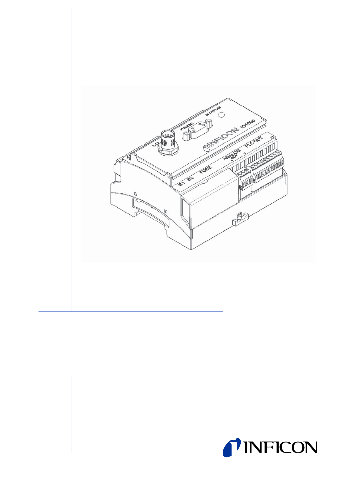
INSTALLATION MANUAL
Type designation
IO1000
Product description
I/O module
Catalog no.
from software version
Document no.
560-310
I/O module 1.0
jiqc10en1-b (1301)
Page 2

This document applies to the software version stated on the cover page. If you need
a different version, please contact our sales staff.
Reprint, translation and duplication need to be approved in writing by
INFICON GmbH.
2
Page 3

Content
1 About this manual . . . . . . . . . . . . . . . . . . . . . . . . . . . . . . 4
1.1 Target groups . . . . . . . . . . . . . . . . . . . . . . . . . . . . . . . . . . . . . . . . . . . . 4
1.2 Other applicable documents . . . . . . . . . . . . . . . . . . . . . . . . . . . . . . . . . 4
1.3 Presentation of information . . . . . . . . . . . . . . . . . . . . . . . . . . . . . . . . . . 4
1.3.1 Warnings . . . . . . . . . . . . . . . . . . . . . . . . . . . . . . . . . . . . . . . . . 4
1.3.2 Text markings . . . . . . . . . . . . . . . . . . . . . . . . . . . . . . . . . . . . . 5
2 Safety . . . . . . . . . . . . . . . . . . . . . . . . . . . . . . . . . . . . . . . . . 6
2.1 Intended use . . . . . . . . . . . . . . . . . . . . . . . . . . . . . . . . . . . . . . . . . . . . . 6
2.2 User requirements . . . . . . . . . . . . . . . . . . . . . . . . . . . . . . . . . . . . . . . . 6
2.3 User requirements . . . . . . . . . . . . . . . . . . . . . . . . . . . . . . . . . . . . . . . . 6
3 Shipment check, transport, storage . . . . . . . . . . . . . . . . 7
3.1 Checking shipment . . . . . . . . . . . . . . . . . . . . . . . . . . . . . . . . . . . . . . . . 7
3.2 Transport . . . . . . . . . . . . . . . . . . . . . . . . . . . . . . . . . . . . . . . . . . . . . . . 7
3.3 Storage . . . . . . . . . . . . . . . . . . . . . . . . . . . . . . . . . . . . . . . . . . . . . . . . . 7
4 Description . . . . . . . . . . . . . . . . . . . . . . . . . . . . . . . . . . . . 8
4.1 Construction of the I/O module . . . . . . . . . . . . . . . . . . . . . . . . . . . . . . . 8
4.2 Function . . . . . . . . . . . . . . . . . . . . . . . . . . . . . . . . . . . . . . . . . . . . . . . 14
4.3 Technical data . . . . . . . . . . . . . . . . . . . . . . . . . . . . . . . . . . . . . . . . . . 14
4.3.1 Mechanical data . . . . . . . . . . . . . . . . . . . . . . . . . . . . . . . . . . 14
4.3.2 Electrical data . . . . . . . . . . . . . . . . . . . . . . . . . . . . . . . . . . . . 14
4.3.3 Ambient conditions . . . . . . . . . . . . . . . . . . . . . . . . . . . . . . . . 14
5 Installation and removal . . . . . . . . . . . . . . . . . . . . . . . . 15
5.1 Mounting of I/O module . . . . . . . . . . . . . . . . . . . . . . . . . . . . . . . . . . . 15
5.1.1 Establish connections . . . . . . . . . . . . . . . . . . . . . . . . . . . . . . 15
5.2 Removing the I/O module . . . . . . . . . . . . . . . . . . . . . . . . . . . . . . . . . . 16
6 Disposal . . . . . . . . . . . . . . . . . . . . . . . . . . . . . . . . . . . . . 1 7
Content 3
Page 4
1 About this manual
1.1 Target groups
This installation manual is intended for the operator and for technically qualified
personnel with experience in leak detection technology and integration of leak
detection devices in leak detection systems. In addition, the installation and use of
the unit require knowledge of electronic interfaces.
1.2 Other applicable documents
Installation manual for mass spectrometer module jiqa54
Interface protocols jira54
1.3 Presentation of information
1.3.1 Warnings
Imminent threat of danger resulting in deat h or se ve re in jurie s
Dangerous situation potentially resulting in death or severe injuries
Dangerous situation resulting in minor injuries
Dangerous situation resulting in damage to property or the environment
4 About this manual
Page 5

1.3.2 Text markings
Marking Meaning
►
1, 2, 3, ... Several instructions in a fixed order
S
MALL CAPS
Information
Requirement for execution of an action
Tool or aid for an action
Instruction
Result of an action
Designation of the unit or command/term from the menu
Useful tips and information
About this manual 5
Page 6

2Safety
2.1 Intended use
The I/O module is a device interface between the MSB box of the mass spectrometer
module LDS3000 and an external controller, for example.
► Install, operate and service the unit only in compliance with this manual.
► Comply with the limits of application (see Chapter 4.3, page 14).
2.2 User requirements
Safety conscious operation
► Operate and install the unit only if it is in perfect working order and as intended,
in a safety-conscious manner and fully aware of dangers, in compliance with this
manual.
► Fulfill and ensure compliance with the following regulations:
– Intended use
– Generally applicable safety and accident prevention regulations
– International, national and local standards and guidelines
– Additional provisions and regulations that are specific to the unit
► Use only original parts or parts approved by the manufacturer.
► Keep this manual available at the operating site.
Personnel qualifications
► All work must be performed only by technical specialists who have been trained
on the unit.
► Allow personnel in training to work with the unit only under the supervision of
technical specialists.
► Make sure that the authorized personnel have read and understood this manual
and all other applicable documents (see Chapter 1.2, page 4), especially the
information on safety, maintenance and repairs, before starting work.
► Define responsibilities, authorizations and supervision of personnel.
2.3 User requirements
► Read, observe and follow the information in this manual and the working
instructions created by the owner, especially the safety instructions and warnings.
► Perform all work based on the complete manual.
6 Safety
Page 7

3 Shipment check, transport, storage
3.1 Checking shipment
Scope of delivery
Article Quantity
I/O module 1
Installation manual 1
► Check shipment to make sure it is complete.
3.2 Transport
Damage due to unsuitable packaging material
Transport in unsuitable packaging material can damage the unit.
► Transport the unit only in the original packaging material.
► Keep original packaging material.
3.3 Storage
► Always store the unit in compliance with the technical data, see Chapter 4.3,
page 14.
Shipment check, transport, storage 7
Page 8

4 Description
PLC-IN PLC-IN
1 Dyn CAL / Normal Cal
1 Dyn CAL / Normal Cal
2 SNIFF / VAC
2 SNIFF / VAC
3 STOP
4 ZERO
5 EXT.CAL
6 INT.CAL
7 CLEAR
8
9
10
11 PLC-IN-GND
3 STOP
4 ZERO
5 EXT.CAL
6 INT.CAL
7 CLEAR
8
9
10
11 PLC-IN-GND
24V-OUT
+
_
0 V
24 V
0 - 24V
PLC/SPS
PLC/SPS
4.1 Construction of the I/O module
Fig: 1 Front view
1 - PLC IN
Digital inputs
Fig: 2 Digital inputs
Electrical insulation (max. 60 V DC, 25 V AC against GND)
Max. permissible input voltage: U = 35 V
Active signal: U = 13 ... 35 V (typically 24 V), I = approx. 7 mA
Inactive signal: U < 7 V (typically 0 V), I = 0 mA
8 Description
Page 9

Connection plug arrangement
The digital inputs can be freely configured.
Pin Name Factory setting mass spectrometer module
1 PLC-IN 1 Dyn CAL / Normal Cal
2 PLC-IN 2 SNIFF/VAC
3PLC-IN 3 STOP
4PLC-IN 4 ZERO
5 PLC-IN 5 EXT.CAL
6 PLC-IN 6 INT.CAL
7 PLC-IN 7 CLEAR
8PLC-IN 8 -
9PLC-IN 9 10 PLC-IN 10 11 PLC-IN-COM COM
► For other layouts, see installation manual for mass spectrometer module
LDS3000.
Key-operated switch
An external key switch with up to three switching outputs can be connected via three
PLC inputs. The key switch can be used to select the access level of the user of the
control unit.
Key 1 - Operator
Key 2 - Supervisor
Key 3 - Integrator
Example for a suitable key switch: Hop + Schuler, No. 444-05
2- RS232
Connection for RS-232
Electrical insulation (max. 60 V DC, 25 V AC against GND)
Connection plug arrangement
Pin Name
2TxD
3RxD
5GND
A normal RS-232 cable must be used for the connection (1:1 connection, RxD and
TxD not crossed, no zero-modem cable).
► Deactivate RS-232 hardware handshake in RS-232 control program.
Description 9
Page 10

If the hardware handshake cannot be deactivated, then the RS-232 cable can be
used as follows:
Fig: 3 Connection with RS-232 cable (in case hardware handshake cannot be
deactivated)
3 - STATUS
Status LED
Color Status Meaning
Red illuminates Unit not functional or defective
Red flashes
Cyan illuminates
Not ready for operation, communication to mass
spectrometer module is not available
Ready for operation; communication to mass
spectrometer module available
Green Flashes quickly Boot loader active, ready for software update
Green Flashes slowly Data reception on RS232
Yellow Flashes slowly Data reception on RS485
4 - ANALOG OUT
Analog outputs (for logging leakage rate and backing pressure)
Electrical insulation (max. 60 V DC, 25 V AC against GND)
Voltage range 0...10V
Precision
±15 mV offset, additional ±1% from measurement (current
output voltage) as linearity error (at 25 °C)
Resolution typ. 2.5 mV
Load >10kΩ
Connection plug arrangement
The analog outputs can be freely configured.
Pin Name Factory setting mass spectrometer module
1 ANALOG-OUT 1
Leak rate mantissa
1 ... 10 V; linear; in used unit
Leak rate exponent
2 ANALOG-OUT 2
1 ... 10 V; 0.5 V / decade; step function;
1 V = 1 x 10
-12
; in used unit
3 ANALOG-OUT-GND -
► For other layouts, see installation manual for mass spectrometer module
LDS3000.
10 Description
Page 11

5 - PLC OUT
PLC_OUT_8
PLC_OUT_7
PLC_OUT_6
PLC_OUT_5
PLC_OUT_4
PLC_OUT_3
PLC_OUT_2
PLC_OUT_1
PLC_OUT_COM
FOA75
FOA75
8
7
6
5
4
3
2
1
0
Digital outputs
Fig: 4 Digital outputs
Electrical insulation (max. 60 V DC, 25 V AC against GND)
Max. permissible load per output: U = 30 V, I = 0.75 A
Fuses for digital outputs 1 ... 4 and 5 ... 8: 2 x 0.75 A
Connection plug arrangement
The digital outputs can be freely configured.
Pin Name Factory setting mass spectrometer module
1 PLC-OUT 1 TRIGGER1 INVERTED
2 PLC-OUT 2 TRIGGER2 INVERTED
3 PLC-OUT 3 TRIGGER3 INVERTED
4 PLC-OUT 4 TRIGGER4 INVERTED
5 PLC-OUT 5 READY
6 PLC-OUT 6 ERROR INVERTED
7 PLC-OUT 7 CAL-REQUEST INVERTED
8 PLC-OUT 8 OPEN
9 PLC-OUT-COM -
► For other layouts, see installation manual for mass spectrometer module
LDS3000.
Description 11
Page 12

6 - FUSE and DIP switch S1, S2
Fuses for digital outputs and DIP switches (under the cover)
Fuses for digital outputs 1 ... 4 and 5 ... 8:
2 x 0.75 A (Schurter: 7010.9800.xx)
DIP switch S1 4321
Factory setting
(default value of the interface protocol by MS module/control unit)
ASCII protocol -010
LD protocol -011
Binary protocol -101
LDS1000 protocol -110
1 = ON, 0 = OFF, – = not used
DIP switch S2 4321
Activate boot mode for software update x+––
Disable bus terminator 120 Ω for RS-485 1x––
1 = ON, + = switching OFF -> ON in operation, – = not used, x = no meaning
7 - LD
Connection for the data cable to the mass spectrometer module
8 - ANALOG IN
Analog input (input voltage range 0 V to 10.8 V)
-000
Connection plug arrangement
1 24V supply (output)
2 GND to 24V supply
3 Analog input (0 V to 10.8 V)
4 GND to analog input
12 Description
Page 13

9 - RS485
Connection for RS-485
D+
D-
RS485
A: aktiv
1
2
3
4
5
I/O-Modul
+5 V
562 Ω
DIP S2-4
120 Ω
562 Ω
0 V
D+
D-
RS485
B: ohne
1
2
3
4
5
+5 V
0 V
I/O-Modul
562 Ω
DIP S2-4
120 Ω
562 Ω
D+
D-
RS485
C: Passiv
1
2
3
4
5
I/O-Modul
+5 V
562 Ω
DIP S2-4
120 Ω
562 Ω
0 V
Fig: 5 RS-485 bus terminator
A: Active bus terminator
B: No bus terminator
C: Passive bus terminator
Electrical insulation (max. 60 V DC, 25 V AC against GND)
Connection plug arrangement
Pin Name
1 Connect pull-up resistor (562 Ω against +5 V) with D+ if necessary
2D+
3D4 Connect pull-down (562 Ω against GND) with D- if necessary
5COM
Information The bus terminator integrated in the I/O module (120 Ω) between D+
and D can be disabled via DIP switches S2-4.
The BUS address is 1.
BUS operation with more than two subscribers is not possible.
10 - 24V OUT
24V output
Connection plug arrangement
Pin Name
++24V
-GND
Information The I/O module is supplied with voltage by the MS module and requires
no separate power supply. The 24V output is not used for voltage
supply to the I/O module.
The 24V output of the I/O module can be used as an active signal for the PLC inputs
and outputs.
Description 13
Page 14

4.2 Function
The I/O module is a device interface between the MSB box of the mass spectrometer
module LDS3000 and an external controller, for example. The I/O module is
equipped with
• one RS-232 connection
• one RS-485 connection
• one analog input
• two analog outputs
• ten digital inputs
• eight digital outputs
4.3 Technical data
4.3.1 Mechanical data
Dimensions (W x H x D) 107.6 mm x 89.7 mm x 76.6 mm
Weight 300 g
4.3.2 Electrical data
Supply voltage 24 V DC
4.3.3 Ambient conditions
Permissible ambient temperature
(during operation)
Permissible storage temperature -20 °C ... 60 °C
Max. relative
humidity
Type of protection IP 20
Pollution degree II
Max. altitude above sea level 2000 m
10 °C ... 45 °C
< +31 °C 80%
+31 °C to +40 °C decreasing linearly from 80% ... 50%
> +40 °C 50%
14 Description
Page 15

5 Installation and removal
5.1 Mounting of I/O module
Fig: 6 Mount bus module on DIN-TS35 top hat rail
DIN-TS35 top hat rail
1 Hook unit on top hat rail at bottom.
2 Press unit onto top hat rail at top.
5.1.1 Establish connections
Connecting I/O module with MSB box
The I/O module communicates via data cable with the mass spectrometer module
and is supplied with voltage by the data cable.
Data cables from INFICON
1 Connect I/O module (connection L
OA
NYBUS).
2 Connect I/O module via desired interfaces with external controller:
– RS232 (RS-232 interface)
– RS485 (RS-485 interface)
–A
NALOG IN (analog input)
–A
NALOG OUT (analog outputs)
–P
LC IN (digital inputs)
D) via data cable with MSB box (connection I/
–P
LC OUT (digital outputs)
Installation and removal 15
Page 16

5.2 Removing the I/O module
Fig: 7 Removal of the bus module
Flat-tip screwdriver
1 Use the flat-tip screwdriver to pull out the locking device.
2 Remove the I/O module from the top hat rail.
16 Installation and removal
Page 17

6 Disposal
The unit can be disposed of by the user.
Information The unit is made of materials that can be reused. By recycling these
materials you reduce waste and environmental impact.
► For disposal, always comply with local and regional environmental and safety
regulations.
Disposal 17
Page 18

INFICON GmbH, Bonner Strasse 498, D-50968 Cologne, Germany
UNITED STATES TAIWAN JAPAN KOREA SINGAPORE GERMANY FRANCE UNITED KINGDOM HONG KONG
Visit our website for contact information and other sales offices worldwide. www.inficon.com
Document: jiqc10en1-b (1301)
 Loading...