

Page 1
O P E R A T I N G M A N U A L
ninb63e1-f (1410)
Type no. ILS500.210.306
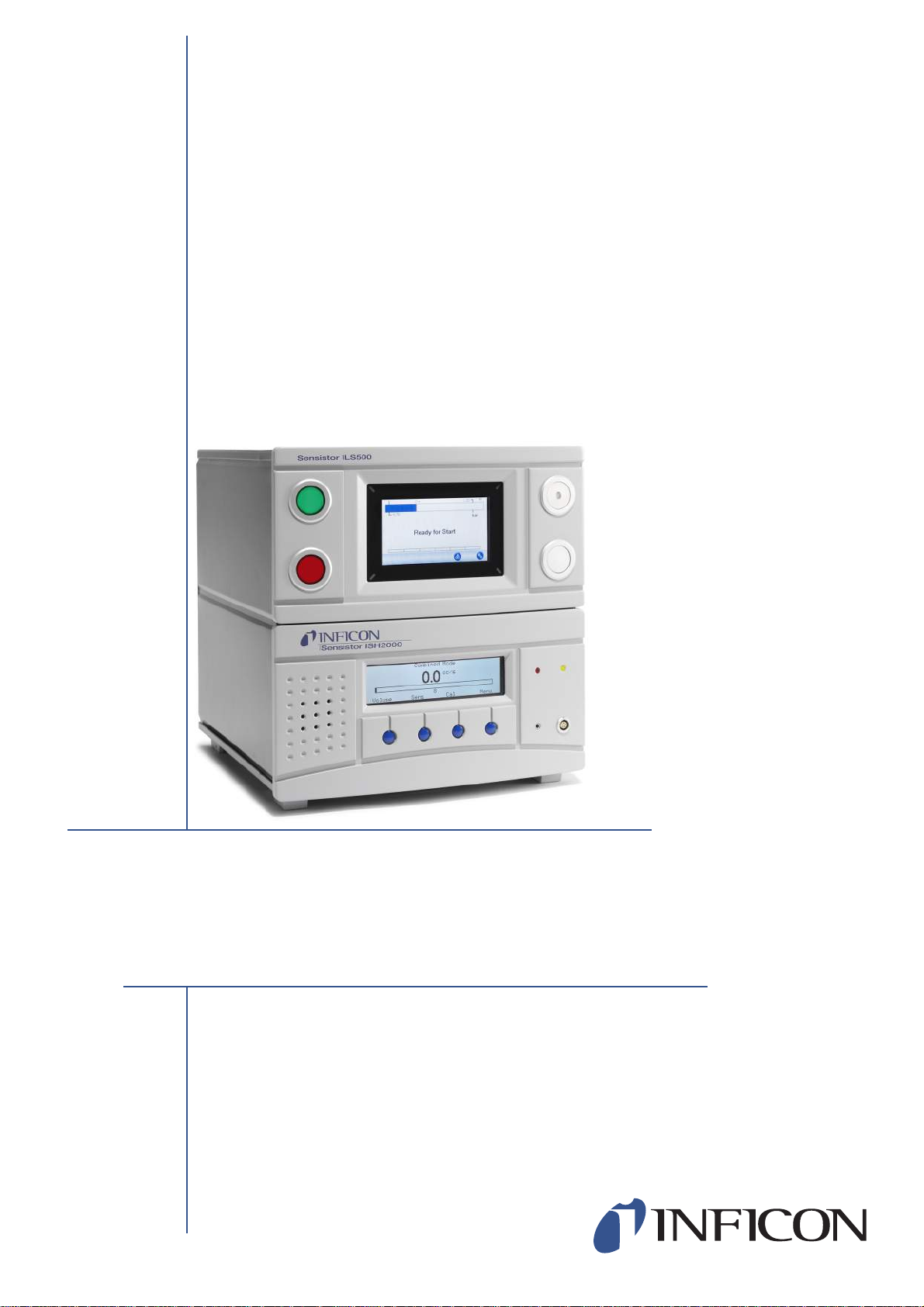
Sensistor ILS500
Hydrogen Leak Detection System
Page 2

Page 3

Content
1 General Information 9
1.1 About This Manual 9
1.2 Related Manuals 9
1.3 Introduction to the ILS500 9
1.4 Disposal 10
2 Equipment and Storage 11
2.1 Supplied Equipment 11
2.2 Required Equipment 12
2.3 Storage 12
3 ILS500 Description 13
3.1 Front View 13
3.2 Rear View (Electrical) 14
3.3 Configuring Ports and Interfaces (Electrical) 15
3.4 Rear View (Pneumatical) 16
3.5 Configuring Ports and Interfaces (Pneumatical) 17
3.6 Labels 17
ninb63e1-f (1410)
4 Hand Probe P50 19
4.1 General Information 19
4.2 Description 19
4.3 Calibration 19
5 System Examples 20
5.1 Simple Hand Probe System 20
5.2 Automatic Chamber Test 21
5.3 Chamber Test with Leak Locating Option 22
6 Setup 23
6.1 Placement of the ILS500 23
6.2 Electrical Connections 24
6.3 Pneumatic Connections 27
6.4 Set Up Test Area 31
7 Menu System 32
7.1 ILS500 Display 32
7.2 Passwords 34
7.3 Menu Overview 35
8 Using the ILS500 40
8.1 Test Sequence 40
8.2 Run a Test 41
Content 3
Page 4

9 Recipes 44
9.1 Recipe Overview 44
9.2 Create a Recipe 45
9.3 Test Settings 46
9.4 Optimizing the Test Cycle 53
10 Calibration 58
10.1 About Calibration 58
10.2 Calibration Overview 58
10.3 How to Calibrate 60
11 Troubleshooting 62
11.1 Fault Symptoms 62
11.2 Perform Hardware Test 62
12 Maintenance Instructions 75
12.1 Software Update 75
12.2 Maintenance Plan 76
12.3 Maintenance 77
12.4 Functional Verification 83
13 Service 84
14 Technical Data 85
14.1 Electrical Specifications 85
14.2 Pneumatic Specifications 86
14.3 Other Data 87
14.4 Interfaces and Connectors 88
15 Spare Parts and Accessories 99
16 Support from INFICON 101
16.1 How to Contact INFICON 101
16.2 Returning Components to INFICON 101
17 Declaration of Conformity 102
18 Declaration by the Manufacturer 103
ninb63e1-f (1410)
Content 4
Appendix
A: Parameter Index 104
Page 5
General Safety Precautions
Definitions of Warning, Caution and Notice
Warning
Indicates procedures that must be strictly observed to prevent hazards to persons.
Caution
Indicates procedures that must strictly be observed to prevent damage to or destruction
of the instrument
.
General Safety
ninb63e1-f (1410)
Notice
Failure to observe the following precautions could result in serious personal
injury:
Indicates special requirements the user must comply with.
Warning
Pure Hydrogen is a flammable gas. Use only ready-made Hydrogen Tracer Gas
comprising 5% Hydrogen in Nitrogen. This is a standard industrial gas mixture used
in a variety of industrial applications.
Warning
Since the tracer gas mix contains no oxygen, releasing large amounts of the gas in a
confined space may lead to asphyxiation.
Warning
Compressed gases contain a great deal of stored energy. Always carefully secure
gas bottles before connecting a pressure regulator. Never transport gas bottles with
a pressure regulator fitted.
5
Page 6
Warning
Pressurizing objects at too high pressures can lead to the object bursting. This in
turn can result in serious injury or even death. Never pressurize objects that have
not previously been burst-tested or have otherwise been approved for the test
pressure you intend to use.
Failure to observe the following precautions could result in damage to the
equipment:
Caution
Do not open the detector! Service of this equipment may only be carried out by
service organizations authorized for this purpose by INFICON.
Caution
If the detector suffers external damage, it must be checked and repaired by a service
organization authorized by INFICON.
Caution
Do not expose the probe to a hydrogen concentration greater than 0.1% when the
instrument is not operating, as this could damage or destroy the probe sensor.
Caution
When the instrument is operating, the sensor can withstand temporary exposure to
hydrogen concentrations up to 100%. Avoid long exposures to high concentrations.
Caution
Always switch power off before connecting or disconnecting any cable.
ninb63e1-f (1410)
6
Page 7

Notice
Whenever the word 'hydrogen' is used in this manual, it implies that the
hydrogen gas is safely mixed with nitrogen in the proportions
95% Nitrogen / 5% Hydrogen.
Before connecting the tracer gas, confirm that the connectors or test
object is designed for operating at the test pressure to be used.
ninb63e1-f (1410)
7
Page 8
Safety ILS500
Warning
The ILS500 must never be introduced to pressures higher than that approved for the
object to be tested and never beyond the ILS500 specification.
Warning
Be sure to have a pressure relief valve in case of accidental tracer gas pressure
increase.
Warning
When dealing with high pressures, a blast protection is needed between the Test
Port and the Test Object.
Warning
When dealing with test objects that cannot stand high pressure increase, make sure
to mount a flow control valve on the Test Ports.
Warning
Make sure not to confound Compressed Air and Tracer Gas.
Notice
INFICON can not take any responsibility for the consequences arising from
inappropriate use of certain test pressures.
The ILS500 has no internal emergency stop circuit. ILS500 is prepared for
integration into an external emergency stop circuit.
Check that all relevant legislation and safety standards are complied with
before putting the ILS500 into service. See further information under
Installation.
ninb63e1-f (1410)
8
Page 9

1 General Information
Please read this Operating Manual carefully before putting your Sensistor ILS500 into
service. When reading, please pay particular attention to the WARNINGS, CAUTIONS
and NOTICES found throughout the text.
1.1 About This Manual
The purpose of this manual is to:
• Describe the working principles of the ILS500 and its different parts
• Show examples of different types of test stations
• Teach the reader how to set up the ILS500 for different test purposes
1.1.1 Document History
Revision Date Remark
e 11-2013 New Tracer Gas Filler with New Hydrogen Leak Detector
f 10-2014 Updated version
1.2 Related Manuals
Extensive information about the Leak Detector can be found in the manuals for the
Sensistor ISH2000:
• Operating Manual Sensistor ISH2000
ninb63e1-f (1410)
• Technical Reference Manual Sensistor ISH2000
1.3 Introduction to the ILS500
The Sensistor ILS500 is an all-in-one Tracer Gas Leak Detection System.The purpose
of the ILS500 is to make it possible to set up a fully automatic leak test system quickly,
to a low cost.
1.3.1 Intended Use
ILS500 is designed for indoor use only.
All functions are accessible and programmable using a touch panel, a PC or via the
Internet. The test sequence is controlled by an integrated controller.
Different sets of parameters can be saved. Each set forming a specific recipe for a
specific test object.
General Information 9
Page 10
1.3.2 Available Configurations
Sensistor ILS500
Sensistor ILS500
Standard For common tracer gas leak detection.
High Pressure (HP) When a higher tracer gas pressure is needed.
The actual configuration is shown on the ILS500 display during start-up and in the
menu when clicking Setup >> Info.
1.4 Disposal
Notice
Start-up time for the leak detectors can be up to 10 minutes, depending
on the condition.
ninb63e1-f (1410)
According to EU legislation, this product must be recovered for
separation of materials and may not be disposed of as unsorted
municipal waste.
If you wish you can return this INFICON product to the manufacturer
for recovery.
The manufacturer has the right to refuse taking back products that
are inadequately packed and thereby presents safety and/or health
risks to the staff.
The manufacturer will not reimburse you for the shipping cost.
Shipping address:
INFICON AB
Westmansgatan 49
582 16 Linköping
Sweden
10 General Information
Page 11
2 Equipment and Storage
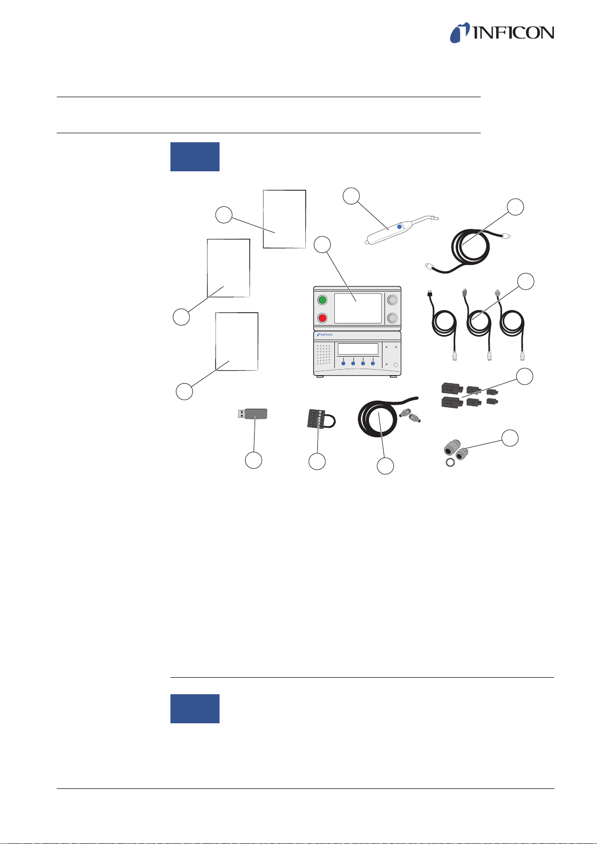
2.1 Supplied Equipment
ninb63e1-f (1410)
Notice
11
10
When receiving the equipment, check that it has not been damaged
during transport.
2
12
OM
ISH2000
OM
ILS500
WARNING
9
PAPER
1
8
7
3
4
5
6
Supplied Equipment
1 ILS500
2 Hand Probe P50
3 Probe Cable (3 m)
4 Power Cables (EU, UK, US)
5 Screw Terminal Connectors for External I/O Signals
6 Thread Converter Set (ISO to NPT Conversion)
7 Hose Connection Kit
8 Safety Override Loopback
9 USB flash drive with other relevant manuals
10 Operating Manual Sensistor ILS500 (this manual)
11 Operating Manual ISH2000
12 Warning Paper about use of Hand Probe
Notice
Accessories to the ILS500 can be found on page 99.
All pneumatic ports are plugged upon delivery. Store the removed plugs.
They are used for future hardware testing.
Equipment and Storage 11
Page 12
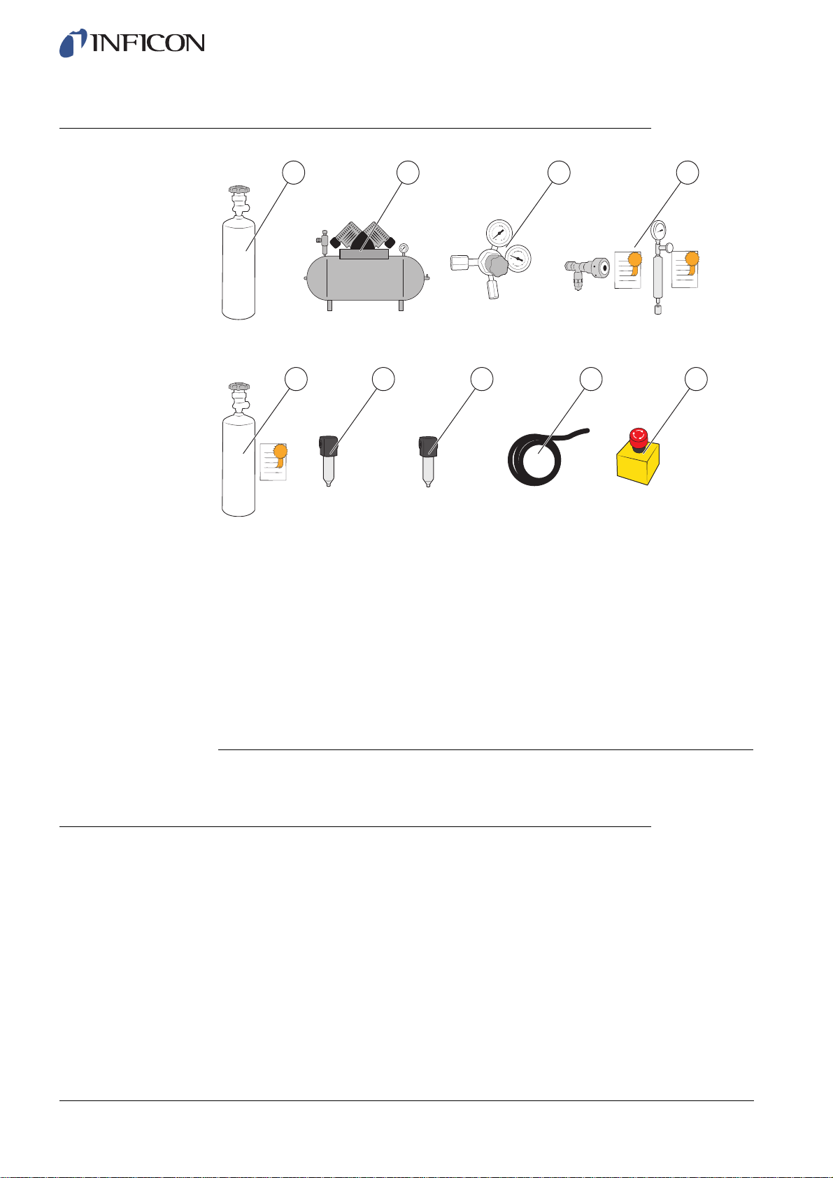
2.2 Required Equipment
1
5 9
Required Equipment
2
6
7 8
3
4
2.3 Storage
1 Tracer Gas
2 Compressed Air
3 Two-Step Gas Regulator
4 Calibration Leak with Certificate (small or large) or
5 Calibration Gas with Certificate
6 Compressed Air Filter
7 Oil Separator (recommended)
8 Exhaust Hose
9 Emergency Stop Circuit (recommended)
For more information, see on page 99.
For prolonged storage, factors such as temperature, humidity, saline atmosphere etc.,
may damage the detector elements.
Please contact your local representative for more information.
ninb63e1-f (1410)
12 Equipment and Storage
Page 13
3 ILS500 Description
ILS500 is manually controlled using the START and STOP buttons and the menu
system of the touch panel. The screen also shows the steps of the test sequence
graphically and in plain text.
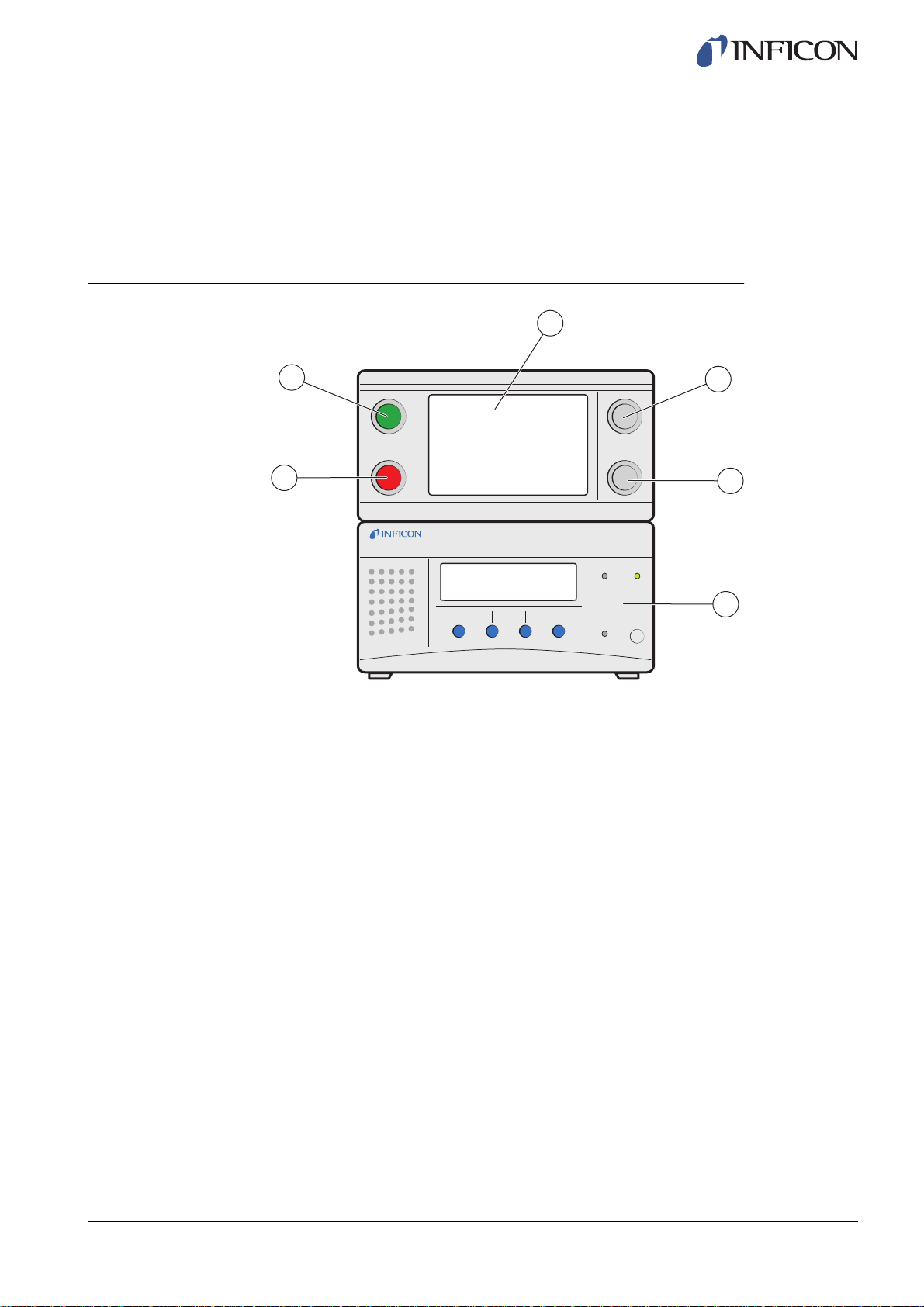
3.1 Front View
3
ninb63e1-f (1410)
2
1
ILS500 Front View
1 Red lamp
2 Green lamp
3 ILS500 Touch panel
4 START button
5 STOP button
6 ISH2000
4
5
6
ILS500 Description 13
Page 14
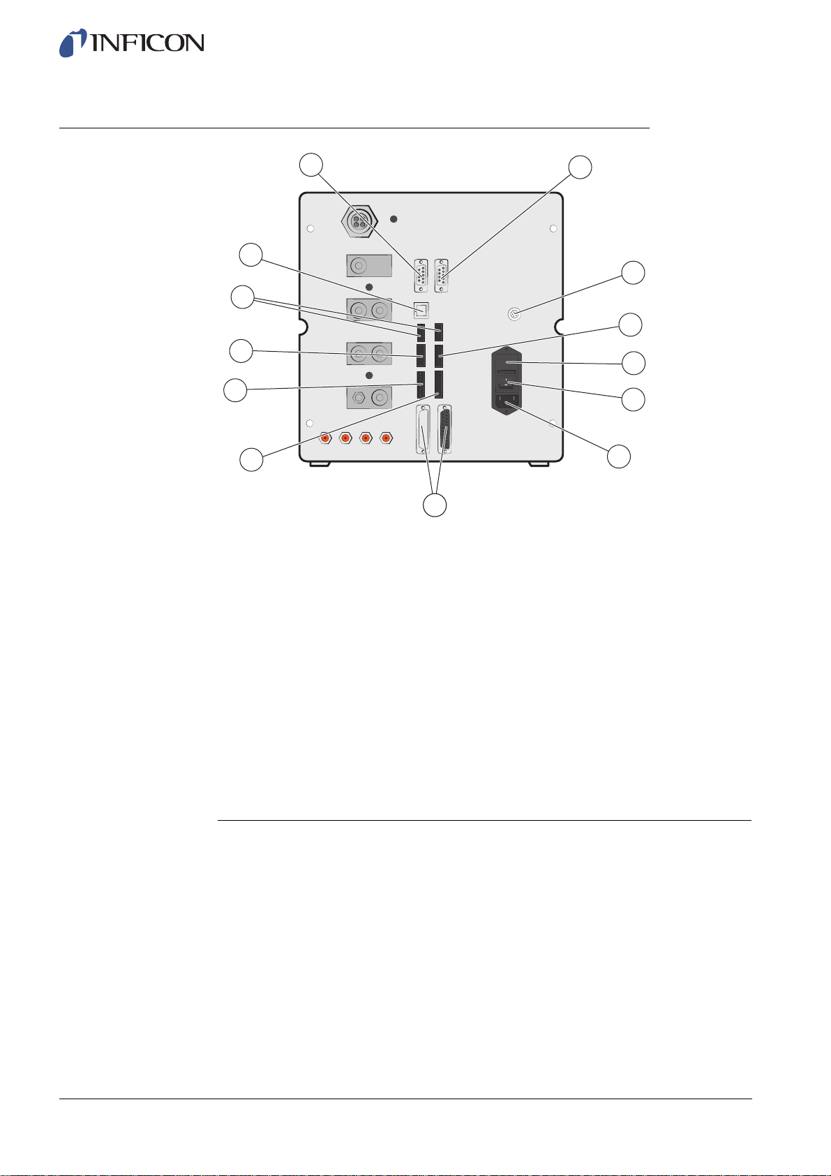
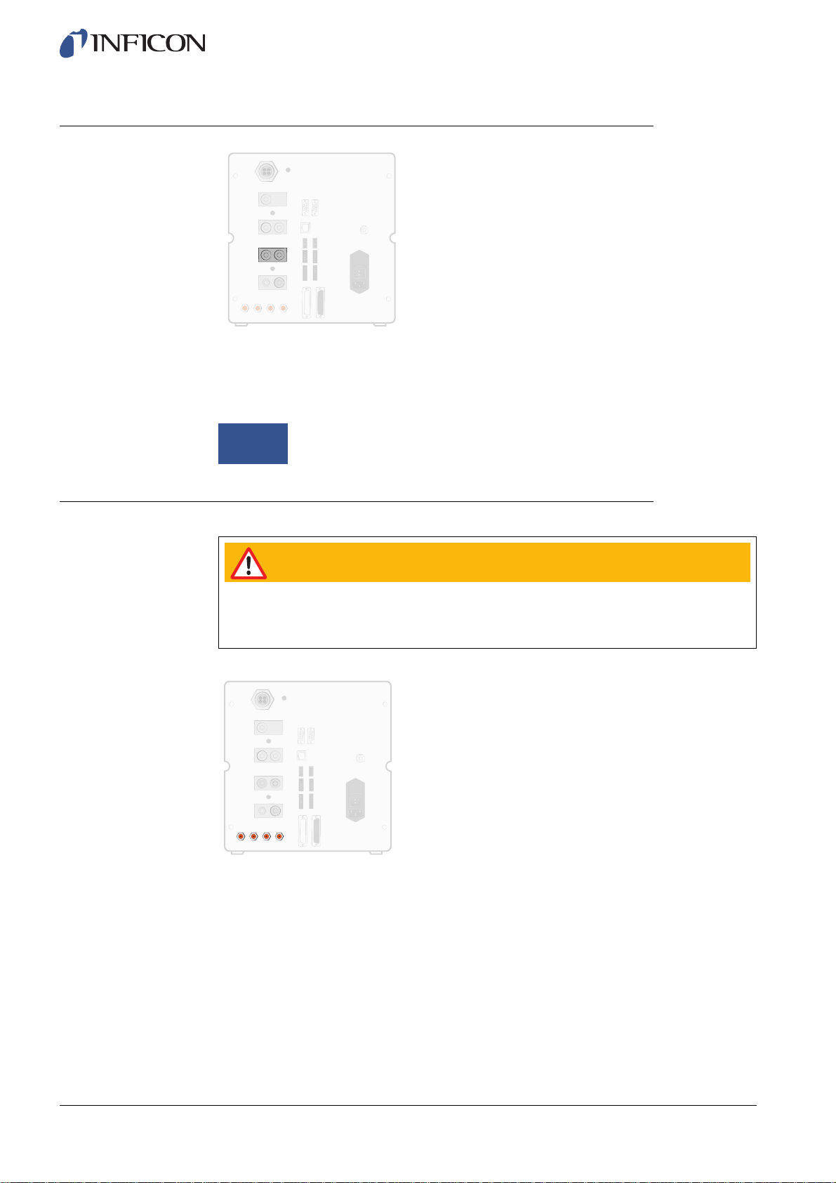
3.2 Rear View (Electrical)
13
12
11
10
9
8
Rear View (Electrical)
1 Leak Detector
2 Connection Port
3 Safety Interface
4 Fuses
5 Power Switch
6 Power Input
7 Probe Control Port
8 Control Output
9 Tooling Interface
10 Status Output
11 Inputs 1 and 2 (optional)
12 Ethernet
13 Printer Port/RS232
1
2
3
4
5
6
7
ninb63e1-f (1410)
14 ILS500 Description
For more information, see on page 85.
Page 15

3.3 Configuring Ports and Interfaces (Electrical)
Port/Interface Connect
Leak Detector File Transfer Cable
(for downloading custom APC drivers)
Pin-to-Pin Cable
(for external mounting of ISH2000)
Connection Port Probe
Safety Interface Emergency Stop Circuit
Power Input Power Cable
Probe Control Port APC Units
Control Output Optional External Valves
Tooling Interface External Tools
Status Output Light Tower etc.
Input 1 (optional) Analogue Input
(not supported by std software)
Digital Input
(not supported by std software)
ninb63e1-f (1410)
Input 2 (optional) Active Holder for Hand Probe
Ethernet Ethernet
(remote view and control of touch panel)
Printer Port/RS232 Serial Printer
Logging Device
(e.g. PC)
Remote Control
(START, STOP etc.)
ILS500 Description 15
Page 16
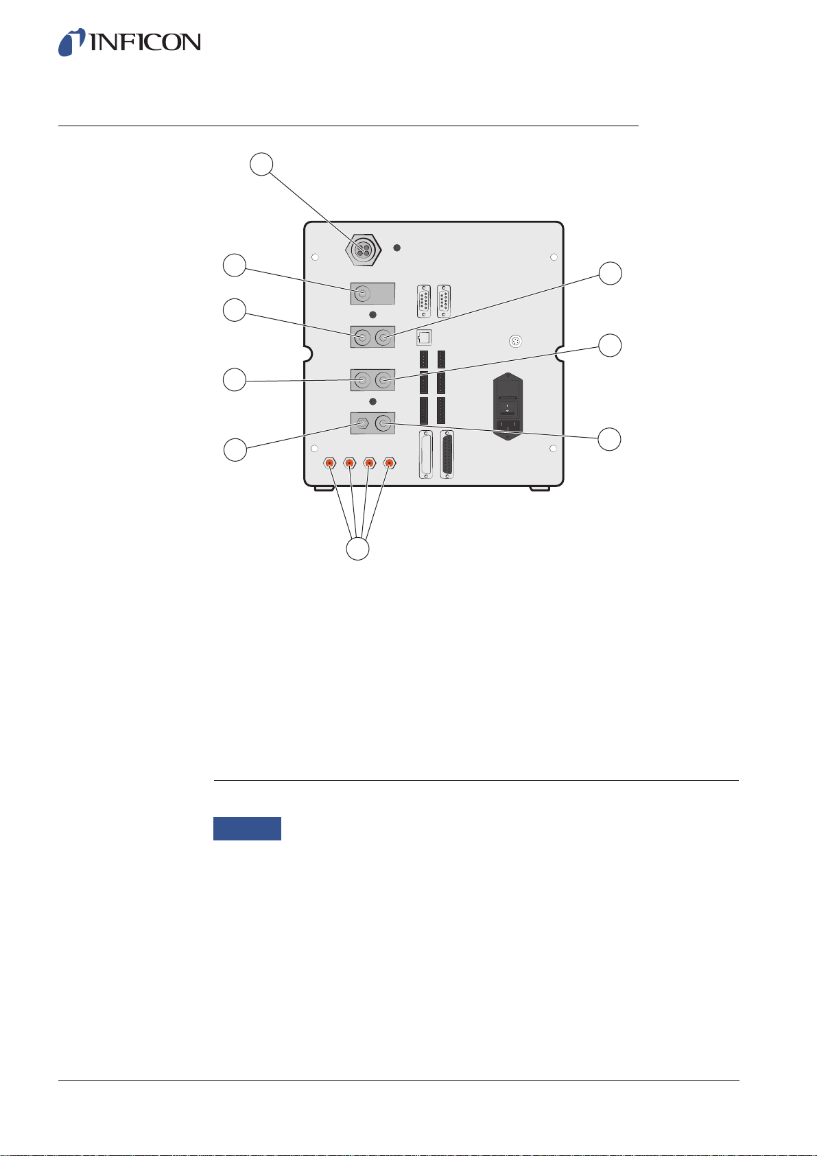
3.4 Rear View (Pneumatical)
9
8
7
6
5
4
Rear View (Pneumatical)
1 Optional Port
2 Test Port 2
3 Compressed Air Input
4 Tooling Valve Outputs 1-4
5 Vacuum Gauge Vent
6 Test Port 1
7 Tracer Gas Input
8 Plugged Port
9 Exhaust
1
2
3
ninb63e1-f (1410)
16 ILS500 Description
Notice
Do not remove the plug from the plugged port in pos. 8.
Page 17

3.5 Configuring Ports and Interfaces (Pneumatical)
Port/Interface Port Thread
Exhaust Barb Fitting:
ID 25 mm (1 in.)
3.6 Labels
ninb63e1-f (1410)
Tracer Gas Input
Test Port 1
Test Port 2
Compressed Air Input
Tooling Valve Outputs 1-4 Hose Connectors:
BSP 3/8" (NPT 3/8" adaptor included)
BSP 3/8" (NPT 3/8" adaptor included)
BSP 3/8" (NPT 3/8" adaptor included)
BSP 3/8" (NPT 3/8" adaptor included)
OD 4 mm (0.16 in.)
Machine Plate
Tooling Plate
ILS500 Description 17
Page 18

Pneumatical Plate Electrical Plate
ninb63e1-f (1410)
18 ILS500 Description
Page 19
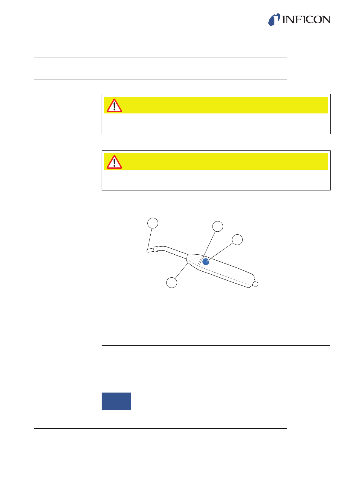
4 Hand Probe P50
4.1 General Information
Caution
Do not expose the probe to a hydrogen concentration greater than 0.1% when the
instrument is not operating, as this could damage or destroy the probe sensor.
Caution
Connection and disconnection of the sensor cable must be done with power OFF.
Sensor can be damaged if power is on.
4.2 Description
ninb63e1-f (1410)
1
2
3
4
Hand Probe P50 (Rigid Neck)
1 Hydrogen Sensor
2 Indicator LED lamps
3 Function Button
4 Lamps
The Hand Probe P50 is a non-sniffing probe. Gas analysis takes place in the
replaceable sensor located in the tip of the probe.
For more information about the Hand Probe P50, refer to the Operating Manual and
Technical Reference Manual for Sensistor ISH2000.
Notice
4.3 Calibration
The probe needs to be calibrated for optimal accuracy. Make sure it is calibrated when
it is used for the first time. For more information about calibration, see on page 58.
The probe can be ordered with a flexible neck. For more information, see
on page 99.
Hand Probe P50 19
Page 20
5 System Examples
ILS500 is equipped with a large number of functions for connection and leak testing of
different kinds of objects. It is therefore possible to build a leak test station that suits the
tested object and the requirements on testing speed etc.
Three examples of test stations are given in the following sections.
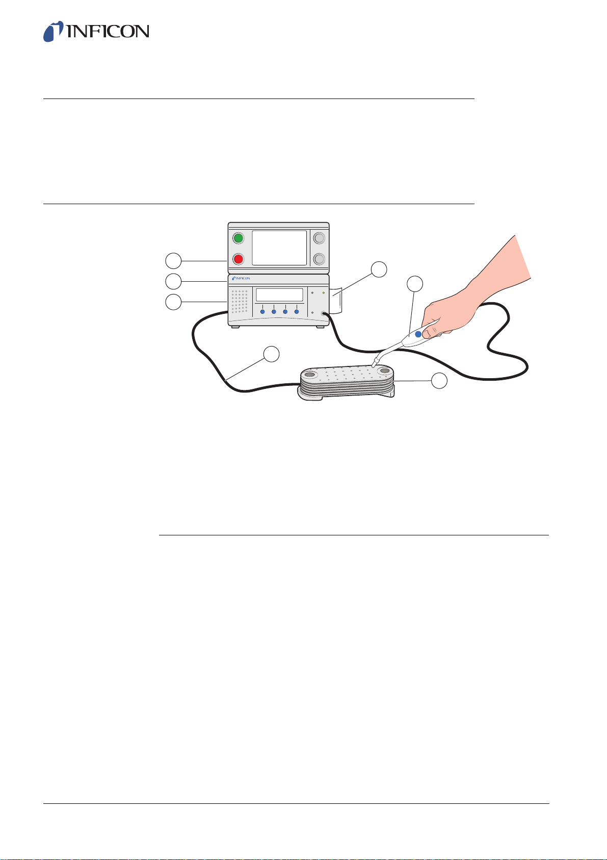
5.1 Simple Hand Probe System
1
7
2
6
3
4
5
Simple Hand Probe System
1 Power Connection
2 Compressed Air Connection
3 Tracer Gas Connection
4 Evacuation and Gas Filling
5 Test Object
6 Hand Probe
7 Active Probe Holder (optional)
In this system the operator is manually handling the Hand Probe for the leak test and
the test fixture (Tooling).
ILS500 ensures that the tracer gas correctly fills the entire object.
Filling and Gross Leak Test (if desired) are performed automatically and the gas leak
test is conducted manually by the operator.
An Active Holder for Hand Probe (option) can be used to ensure that the selected
minimum test time is used.
ILS500 will indicate LEAK if any of the tests fails.
ninb63e1-f (1410)
20 System Examples
Page 21
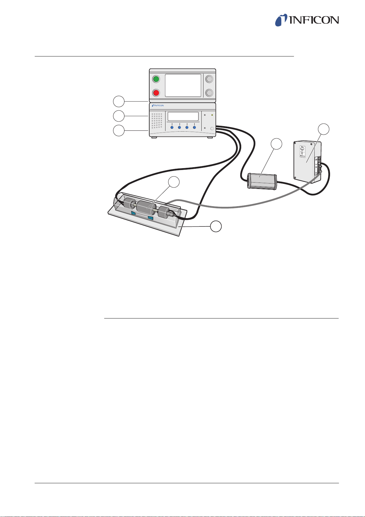
5.2 Automatic Chamber Test
1
2
ninb63e1-f (1410)
3
4
Automatic Chamber Test
1 Power
2 Compressed Air
3 Tracer Gas
4 Test Object
5 Test Chamber
6 Automatic Probe, AP29 ECO
7 COMBOX
6
7
5
This example is using the integrated tooling system for automatic connection of the
tested object. ILS500 will automatically fill the object with tracer gas, and maintain the
correct pressure.
An automatic gas leak test is performed after filling and accumulation of leaking gas in
the test chamber. The gas test is made using the Active Probe AP29. ILS500 will signal
LEAK if leakage above the set limit is registered.
The tracer gas is automatically removed after the test and the tooling system
disconnects the test fixture.
System Examples 21
Page 22
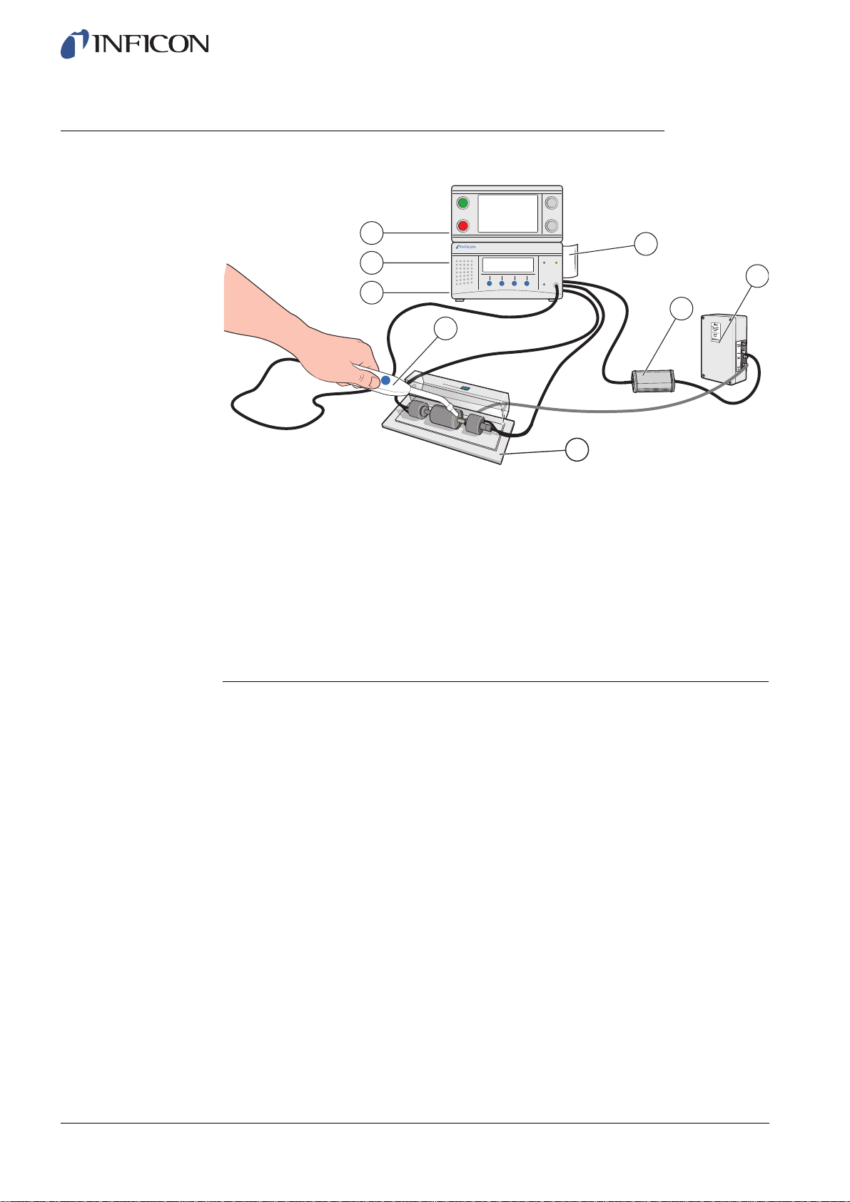
5.3 Chamber Test with Leak Locating Option
1
2
3
4
Chamber Test with Leak Locating Option
1 Power
2 Compressed Air
3 Tracer Gas
4 Hand Probe
5 Test Chamber
6 Automatic Probe, AP29 ECO
7 COMBOX
8 Active Probe Holder (optional)
8
6
7
5
ninb63e1-f (1410)
In this system example the ILS500 includes an Active Holder for Hand Probe, a Hand
Probe and a Automatic Probe. This enables you to combine a leak test with a Active
Probe with leak locating with a Hand Probe.
The Active Probe first measures within the chamber. The extra Hand Probe will be
automatically activated if a leak is detected and the operator can immediately open the
chamber and locate the leak.
The Detector automatically switches over to locating mode when the probe is lifted
from the holder. The gas in the object under test is automatically removed when the
probe is replaced in the holder.
The operator can skip the locating process by pressing STOP instead of lifting the
probe.
22 System Examples
Page 23
6 Setup
Caution
Check that you comply with all relevant legislation and safety standards before
putting your ILS500 into service.
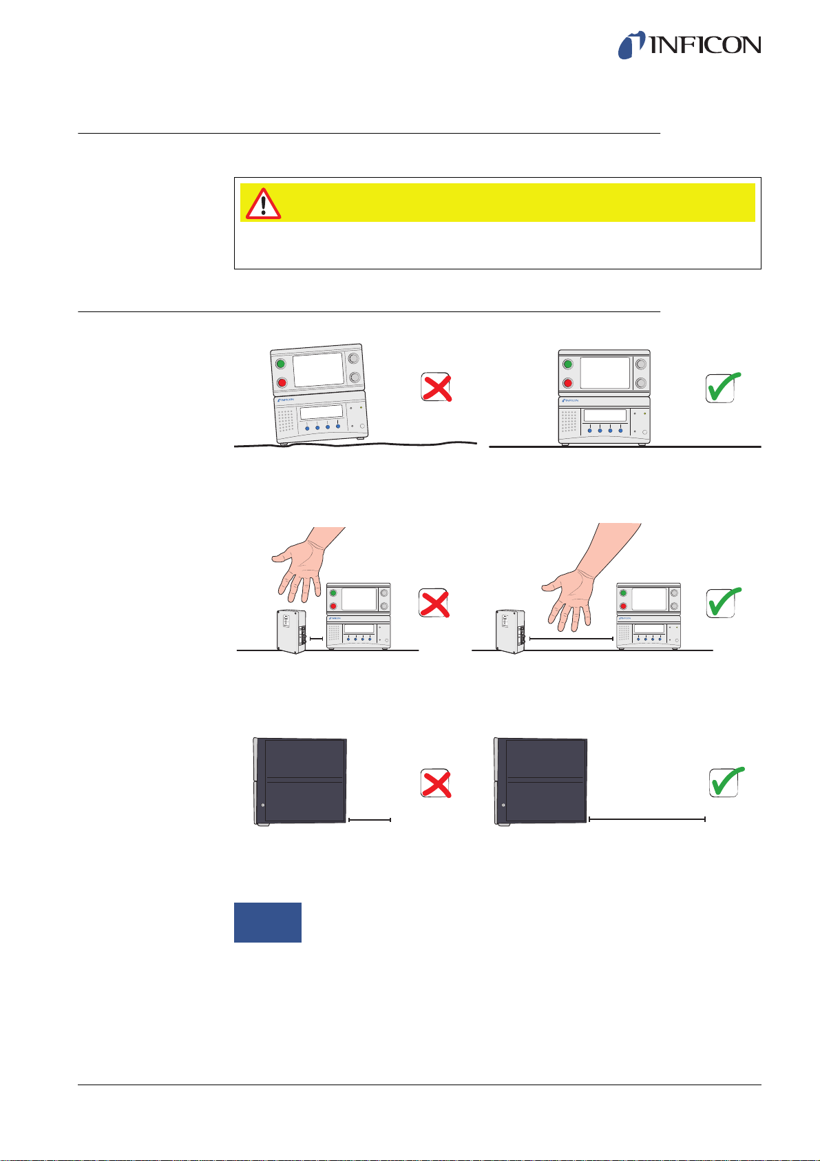
6.1 Placement of the ILS500
Place the ILS500 on a flat surface, as close as possible to the test fixture and
ventilation system.
ninb63e1-f (1410)
Some free space must be provided around the ILS500 to enable maintenance and
service access.
≥350 mm (14 in.)
Ensure that there is at least 350 mm (14 in.) of free space behind the ILS500 to enable
removal of service hatches, connection of supplies, test fixture etc.
Notice
The front feet under the ILS500 can be flipped out to raise the front for a
better viewing angle.
Setup 23
Page 24
Avoid to place the ILS500 close to hydrogen sources such as cigarette smoke,
combustion engines, aluminum machining, lead battery charging stations and
compressed air systems.
6.2 Electrical Connections
6.2.1 Setting Up an Emergency Stop
Caution
To short-circuit is not recommended and should only be made for preliminary testing
before connecting compressed gases or test tooling with moving parts.
ninb63e1-f (1410)
24 Setup
You have the following two options to prepare the ILS500 for start:
• Connect the ILS500 through an external emergency stop relay.
• Short circuit the SAFE SPLY terminal to “+24 V” on the Safety Connector.
Use the Safety Override Loopback delivered with the unit.
Notice
ILS500 will not start testing unless an emergency circuit has been
installed.
Page 25
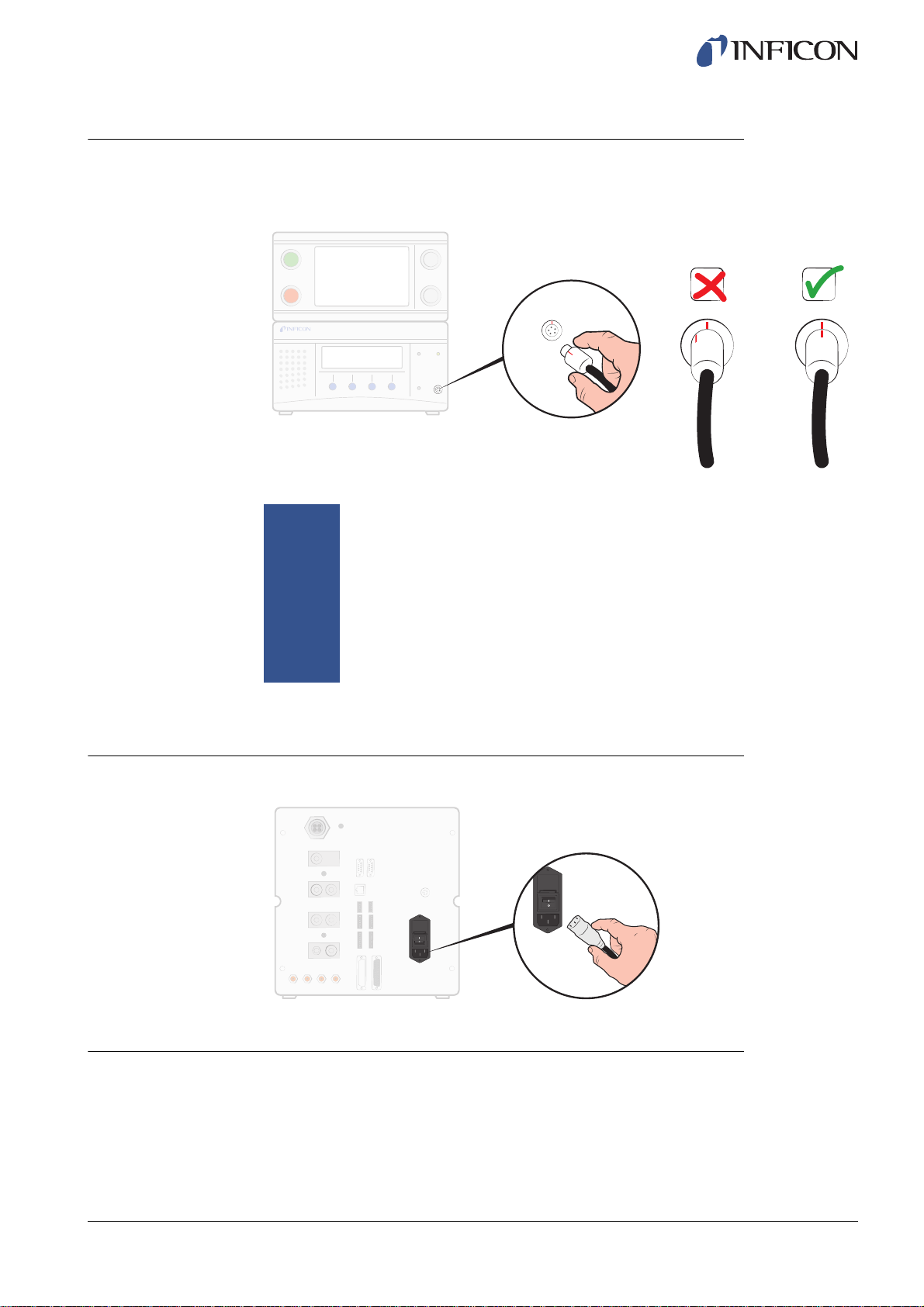
6.2.2 Connecting the Probe
1 Use the Probe Cable to connect the Probe to the ILS500.
Probe connectors are placed on the front and rear of the unit.
ninb63e1-f (1410)
6.2.3 Connecting to Mains
1 Plug the Power Cable into the Power Inlet of the ILS500 and into the nearest socket.
Notice
If you have purchased another type of probe than the Hand Probe P50,
refer to the manual for that probe. There may be other connections in
addition to the Probe Cable.
To disconnect the Probe, hold around the knurled part of the connector
and pull straight out.
Standard cable length is 3 m (10 ft.). Several different cable lengths are
available.
For more information, see on page 99.
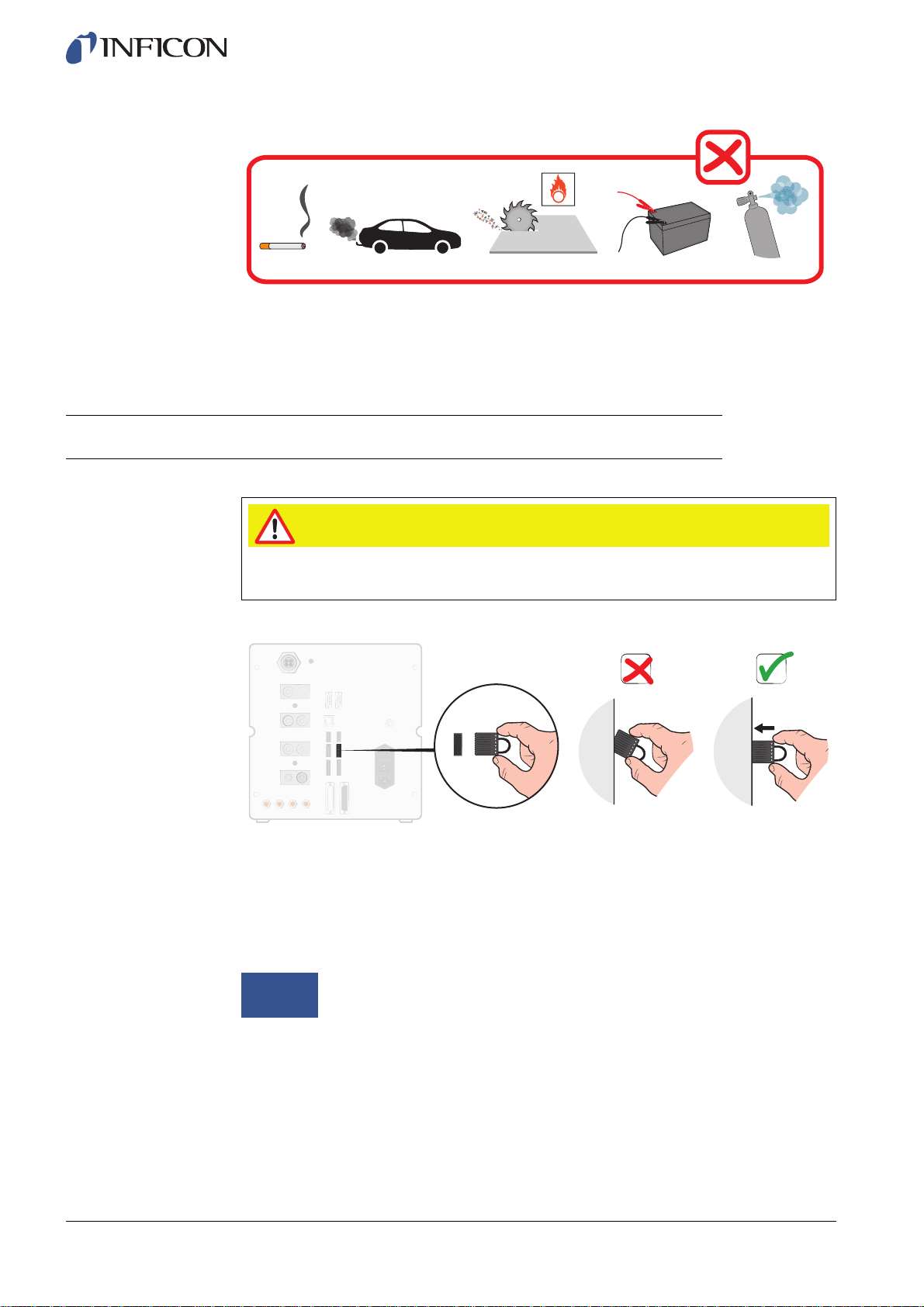
6.2.4 Connecting Extra Features
When using the ports for Options, Status, Tooling and Control, make sure to mount the
connectors as shown below.
Setup 25
Page 26
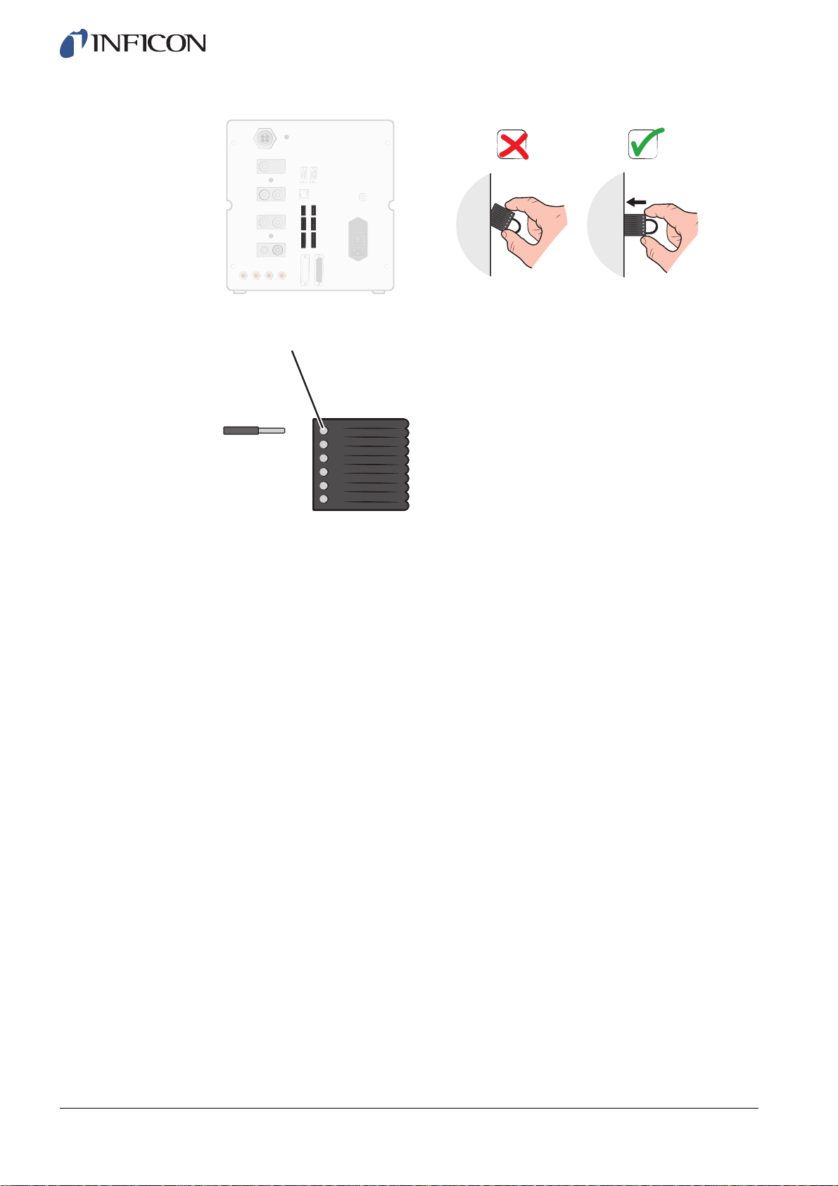
Top pin is number 1
For more information about the connection ports, see on page 85.
ninb63e1-f (1410)
26 Setup
Page 27
6.3 Pneumatic Connections
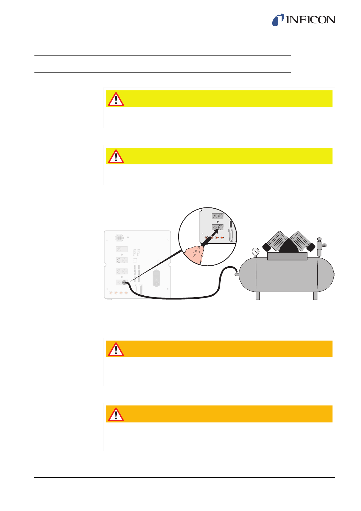
6.3.1 Connecting Compressed Air
Caution
Make sure that compressed air is dry, well filtered and oil free. Recommended filter
grade is 5 μm or finer. Inadequate filtering will result in increased maintenance.
Caution
Make sure to use adequate pressure and flow. For more information, see on page
86.
1 Use the hose to connect the compressor and the ILS500.
ninb63e1-f (1410)
6.3.2 Connecting Tracer Gas
Pressurizing objects at too high pressures can result in a burst object. This in turn
can result in serious injury or even death. Never pressurize objects that have not
previously been burst tested or otherwise approved for the chosen test pressure.
Pure Hydrogen is a flammable gas. Only use ready-made Hydrogen Tracer Gas of
5% Hydrogen in Nitrogen. This is a standard industrial gas mixture used in various
industrial applications.
Warning
Warning
Setup 27
Page 28
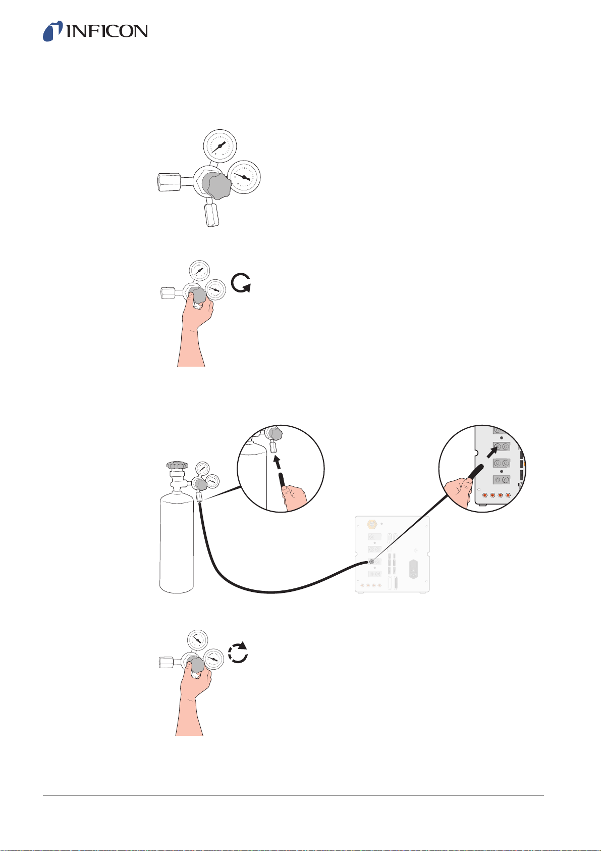
1 Secure gas cylinder safely.
2 Open the cylinder valve briefly to blow out dirt that may have collected in the outlet.
3 Install the two stage gas regulator on cylinder.
4 Turn regulator fully counter clockwise for zero output pressure.
5 Connect a regular welding gas hose or similar between the Tracer Gas Port and the
pressure regulator. Check that the hose is certified to withstand the maximum output
pressure of the regulator.
6 Open cylinder valve and set regulator to desired pressure. See warning banner!
ninb63e1-f (1410)
28 Setup
7 Open regulator outlet valve (if any).
Page 29

6.3.3 Connecting Exhaust to Air Vent
Min 2 m (6.5 ft.)
Ø ≥100 mm (4 in.)
ninb63e1-f (1410)
Max 10 m (30 ft.)
Ø ≥25 mm (1 in.)
3
2
1
Exhaust Recommendation
1 ILS500
2 Exhaust Hose
3 Bleed Air
• The exhaust gas should be directed out of the building.
It is best placed on the roof of the building, far away from the fresh air intake of the
test station.
• It is recommend that a dedicated duct is installed. Install an electric duct fan and an
optional wind extractor.
• It is not recommended to use the general ventilation system to ventilate the exhaust.
If the ventilation system is equipped with energy recirculation there is a big risk that
large amounts of tracer gas will be carried back to the test room thus disturbing the
testing.
Notice
Inadequate exhaust installation is the most common reason for problems
with tracer gas leak testing.
Too narrow or too long exhaust line will result in reduced evacuation
capacity and thereby increased cycle time.
Setup 29
Page 30
6.3.4 Connecting to Test Port 1 and 2
• Use both Test Ports if applicable.
• Hose ID ≥8 mm (0.31 in.).
• The hoses should be as short as possible.
Notice
6.3.5 Connecting Tooling
Warning
Be aware that the faster the connection is made, the higher the risk for injury. Be
careful and install guards etc, according to local legislation and safety standards so
that your fixture is safe to use.
The larger the test object, the more important to follow the
recommendations above.
ninb63e1-f (1410)
30 Setup
Tooling Valve Outputs 1-4 is available for connection of external Tooling.
If the test object has 2 or more ports, connect to ports on opposite sides of object.
Page 31

6.4 Set Up Test Area
Large distance
2
1
Test Area Recommendation
1 Fresh Air Fan
2 Exhaust Fan
3 Test Area
4 Test Building
• Place fresh air intake on outer wall of building.
• Place air intake far away from tracer gas exhaust, cargo bays and other hydrogen
sources.
• Do not use compressed air as fresh air supply.
Industrial compressed air often contains varying and substantial amounts of
hydrogen.
4
3
ninb63e1-f (1410)
1
4
2
3
Fresh Air Curtain Recommendation
1 Fan
2 Local Air Jet
3 Test Object
4 Filter
• Try to create a laminar flow over the test area.
• Curtain should cover the entire test area (test hood or sample point) and extend at
least 0.5 m outside the area.
• Air speed in curtain should be rather low, typically 0.1 m/s.
• Additional small fan(s) can be set up within the curtain for directional purging of test
chamber etc.
Setup 31
Page 32

7 Menu System
7.1 ILS500 Display
1
1 Status Bar
2 Main Display
3 Navigation Button Bar (varies depending on menu)
7.1.1 Menu Buttons
Use the menu buttons for quick navigation.
-0,70
- 0 +
Ready for Start
5,00
bar
2
3
ninb63e1-f (1410)
Calibrate Load Recipe
Settings Home
32 Menu System
Page 33

7.1.2 Navigation and Other Buttons
Go Back Escape
Previous Page
(changes will be saved)
Activated Unactivated
Selected Deselected
Save
(only shown if USB is connected)
Open switch Closed switch
7.1.3 Entering Numbers and Text
To change a value:
1 Click on the value.
A numeric or alphanumeric on-screen keyboard will open.
ESC
(changes will not be saved)
Next Page
Load
ninb63e1-f (1410)
2 Enter the desired digits or characters.
3 Click on the enter symbol to store the new value.
1 2
3
Esc a b c d e f Del
ghi jklmn
opqr stuv
wxy z, .?
Shift A..1
Ctrl
4
5
1 Escape
2 Delete
3 Enter
4 Control
5 Upper/Lower Case and Numbers
987
4
56
12
-0,
3
1
Esc
2
Del
3
Menu System 33
Page 34

7.2 Passwords
To access the menus, use default password "1234" for "Service". The password can be
changed under Settings / Advance Settings / Password.
Passwords
Notice
7.2.1 Set Up New User
1 Click Settings >> Advance Settings >> Passwords to enter Passwords menu.
2 Click Log In and log in as Service.
3 Click Setup User.
4 Click Add.
Log In
Log Out
Setup User
Remember to change the passwords of all menus you want to protect.
Anyone using this manual can access the system if you keep the default
password.
Setup excl. Tooling
Adv. Setup excl. Service
Calibrate
Select Recipe
Service Menu
ninb63e1-f (1410)
5 Fill in user name and password for new user.
6 Click Next.
7 Select Security Group by checking the appropriate boxes.
8 Click Finish.
34 Menu System
Page 35

7.3 Menu Overview
For information about parameter factory default settings, see on page 104.
Notice
The instrument is equipped with a Leak Detector ISH2000, which means
that some settings are blocked. These settings are accessed using the
ILS500 operator panel.
Calibration
Load Recipe
Settings Hardware Setup
Test Settings Tooling Connection
Pre Evacuation
Gross Leak Test Vacuum Decay Test
Pressure Decay Test
Tracer Gas Filling
Blockage Test
Tracer Gas Test
Gas Evacuation
Tooling
Disconnection
ninb63e1-f (1410)
Advanced Settings Timers
Pressures
Options
ISH2000
Service Menu Outputs
Inputs
Analog Inputs
System Reset
ILS500
RS232
Service Run
Hardware Test
Passwords
IP-Settings
Calibration Settings
Recipes
Statistics
Menu System 35
Page 36

Settings Region Time Zone, Region
7.3.1 Settings
and Daylight
Time and Date
Language
Info
Hardware Setup
Hardware setup, one Probe connected.
ninb63e1-f (1410)
36 Menu System
Hardware setup, two Probe connected.
Page 37

Test settings
For more information see chapter 9 on page 44.
Advanced Settings
Advanced Settings
ninb63e1-f (1410)
Timers
Pressures
Options
ISH2000
Advanced settings to fine tune the fill cycles and settings for service staff.
Service Menu
Passwords
IP-settings
Calibration Settings
For more information, see chapter 10 on page 58.
Menu System 37
Page 38

Recipes
For more information, see chapter 9 on page 44.
Statistics
Statistics
Total:
Accepted:
Rejected:
Evacuation:
Vacuum Decay:
Blockage:
Gas Fill:
Pressure Decay:
Gas Test:
0
0
0
0
0
0
0
0
0
Print
Reset
Press 3 sec
Information about test statistics and number cycles events during a test period.
For more information see on page 88.
Region
Region settings.
ninb63e1-f (1410)
38 Menu System
Page 39

Language
Language
English
Japanese
German
Language settings.
Info
Info
Type: ILS500
Serial number: 0
CPU software v 3.00.08
Display version: 3.00.09
Backup Battery Level (3,0 V)
Brightness display
Swedish
Italian
ninb63e1-f (1410)
Instrument information, software versions, battery status and display light settings.
Menu System 39
Page 40

8 Using the ILS500
Warning
Ensure that the tracer gas supply pressure (feeding the ILS500 tracer gas inlet) is
set up properly.
Caution
To abort a test sequence and reset to standby, press STOP for 3 s.
Notice
8.1 Test Sequence
Step Comment
1 Standby ILS500 is idle waiting for Start Signal.
2 Tooling Connection Four Air Valves and four Proximity Switch Inputs can
3 Pre Evacuation
Gross Leak Test 1Evacuation Timeout
The following description is an example for illustration only. The design of
the text fixture, the use of probe(s) and tooling functions etc. should be
adapted to suit your particular application.
ninb63e1-f (1410)
be set up to control moderate test fixtures. Controller
can be expanded for more demanding fixtures.
The air is evacuated from the test object and a first
gross leak test is made simultaneously. The Gross
Leak tests are used to detect larger leaks by pressure
changes.
Evacuation is often necessary to ensure that the
Tracer Gas reaches all parts of the tested object, and
to secure that the tracer gas concentration as high as
possible.
40 Using the ILS500
4 Gross Leak Test 2-
Vacuum Decay Test
Applicable for:
• very long objects (e.g. pipes or heat exchangers).
• low fill pressures (<1 atm).
Less appropriate:
• if the test object does not tolerate underpressure.
• at higher test pressures (Fill Setpoint).
Can be used to reveal leaks before filling with gas.
This minimizes spillage from gross leaks.
Page 41

Step Comment
5 Tracer Gas Filling Tracer gas filling before gas test.
6 Blockage Test
7 Gross Leak Test 3-Gas
Pressure Decay Test
8 Tracer Gas Test The main leak test. This test can be manual using a
9 Gas Evacuation For fast removal of tracer gas after test. Can also
10 Tooling Disconnection Disconnection of test fixture.
• Reveals internal blockages in tested object.
• Ensures that connection lines and test fixture are
correctly connected.
The test object is filled through Test Port 1 while the
pressure is recorded in Test Port 2. Practical for
testing e.g. capillaries etc.
Performed in parallel with tracer gas test.
Can be used for integral testing in parallel with a more
sensitive gas test at selected points.
Hand Probe or fully automatic using an Active Probe.
include an efficient air purge.
ninb63e1-f (1410)
8.2 Run a Test
Notice
The ILS500 will communicate through the lamps and messages on the display.
Lamp Status Indication
Red ON Acknowledge a leak.
Green ON Test sequence is over and the tested object
Yellow
(START Button)
Several of the steps are optional and can be turned off.
Chosen settings can be saved as a Recipe. For more information, see on
page 44. It is also possible to combine two recipes in one test sequence.
Contact your local supplier for more information and individual settings.
Tested object rejected.
General error.
accepted.
Flashing ILS500 is in stand by.
ON The test sequence is running.
8.2.1 Start Up
1 Turn the ILS500 on.
2 Wait for Ready to Start to show on the display.
3 Click Load Recipe and choose a preset recipe, or follow the instructions in the
section on page 45.
Using the ILS500 41
Page 42

8.2.2 Place the Test Object
1 Place the test object in the Test Chamber or connect it to one, two or more
connection ports.
2 Connect any extra equipment needed.
8.2.3 Perform a Test
Caution
Do not expose the probe to a hydrogen concentration greater than 0.1% when the
instrument is not operating, as this could damage or destroy the probe sensor.
Caution
When the instrument is put into operation the sensor withstands temporary
exposure to hydrogen concentration up to 100%. Avoid long exposures to high
concentrations.
Automatic Gas Test
1 Press Start on the ILS500 or wait approximately 4 seconds if automatic start is
activated.
2 When ready – Check the result on the display and lamps.
Manual Gas Test
1 Press Start on the ILS500.
2 Move the Hand Probe close to and along the pressurized test object.
3 A chime sound indicates the detection/location of a leak. A small leak can be more
precisely located by moving the probe over the leak again.
4 Remove the probe promptly.
5 Check the result on the display and lamps.
Notice
For more information about manual testing, refer to ISH2000 manuals and
manual(s) for chosen probe(s).
It is good practice to detect a leak, locate it, and then immediately remove
the Hand Probe to avoid saturation. The probe is not damaged by long
time exposure, but it will recover more slowly. After excessive exposure,
the probe will be less sensitive for a short period of time.
ninb63e1-f (1410)
42 Using the ILS500
Page 43

8.2.4 Disconnect Test Object
1 Evacuate the gas or release the gas pressure.
2 Remove the test object from the fixture.
Notice
Exercise care in the handling of tracer gas after use. Released tracer gas
contaminates the surrounding air with hydrogen and can comprise
subsequent measurements for some time. Ensure that the tracer gas is
ventilated away from the target area, preferably to the outside of the
building.
ninb63e1-f (1410)
Using the ILS500 43
Page 44

9 Recipes
A recipe is a collection of settings suited for a particular test setup. This is used to have
different settings for different test objects.
9.1 Recipe Overview
Click Settings >> Recipes to enter the three Recipe Setup menus.
Recipe Setup
Use Recipes
Choose at startup
Recipe Setup
Connect with recipe
Load Recipe
Save Recipe Delete Recipe
0
Use from list
Keep Tooling in Test Step
Keep Pressure in Test Step
Recipe Setup
Import from USB
Export to USB
Use Recipes Select the box to activate the recipe handling.
Choose at Startup When power is switched on, the ILS500 prompts
Load Recipe Loads the parameters of chosen recipe.
Save Recipe Saves the current settings under chosen recipe
Factory Default
USB Memory connected
the operator to choose recipe.
A new window will open.
name.
A new window will open.
ninb63e1-f (1410)
44 Recipes
Page 45

Delete Recipe Deletes the chosen recipe.
Connect with Recipe Connects two recipes to form one test cycle.
Use from list Shows all saved recipes.
Keep Tooling in Test Step Excludes the disconnection step in the first recipe
Keep Pressure in Test Step Retains gas pressure between two recipes.
Import from USB Imports recipes from connected USB memory.
Export to USB Exports all recipes to a editable file on connected
9.2 Create a Recipe
9.2.1 New Recipe
A new window will open.
Write the name of the recipe to be included, or
choose one from the list in Use from list.
By clicking the blue button the recipe displayed is
added to Connect with recipe.
when two recipes are connected as described
above.
USB memory.
ninb63e1-f (1410)
9.2.2 Modify a Recipe
1 Click Settings >> Hardware to enter the Hardware menu.
Set the correct hardware.
2 Set all ILS500 settings for the test sequence.
For more information, see on page 46.
3 Click Settings >> Recipes to enter the three Recipe Setup menus.
4 Click Save Recipe.
5 Enter a name for the recipe.
6 Click Save.
1 Click Settings >> Hardware to enter the Hardware menu.
Set the correct hardware.
2 Click Settings >> Recipes >> Load Recipe.
3 Select the recipe to modify from the list and click Load.
4 Adjust the ILS500 settings to suit the new recipe.
For more information, see on page 46.
5 Click Settings >> Recipes >> Save Recipe.
6 Enter the name of the new recipe.
7 Click Save Recipe.
Recipes 45
Page 46

9.3 Test Settings
1 Click Settings >> Test Settings to enter the two Test Settings menus.
Test Settings
Tooling Connection
Pre Evacuation
Gross Leak Test
Tracer Gas Filling
Test Settings
Blockage Test
Tracer Gas Test
Gas Evacuation
Tooling Disconnection
ON
ON
Setup
Setup
2 Set which steps to include in the test sequence by selecting the ON boxes.
3 Click Setup to the right of each selected step to enter the Setup menus.
Notice
9.3.1 Tooling Connection
Connection Sequence menu shows the settings made for Tooling Connection.
Connection Sequence
Stand by
Step
Step
Step
Test
For more information about each step, see on page 40.
Tooling Outputs
2341
ON
1
ON
2
OFF
3
ninb63e1-f (1410)
46 Recipes
1 Click on the Settings symbol to edit the settings.
Notice
Up to four connection steps can be programmed.
Page 47

Stand-By
STAND-BY
Go to next step with
Tooling Outputs
ON
and Tooling Inputs
1234
Start Button
ninb63e1-f (1410)
Delay
1 Click on the Tooling Outputs to be activated in stand-by (between tests).
2 Choose how to move on to the next step.
- Set action in list.
- Select Tooling Inputs.
3 Set desired delay time.
0.0
Connection Step 1 — 3
Connection Step 1
ON
Tooling Outputs
Go to next step with
and Tooling Inputs
Info
1234
ON
Auto
Delay
0.0
1 Select the ON check box to activate the step.
2 Click on the Tooling Outputs to be activated.
3 Choose how to move on to the next step.
- Set action in drop-down-list.
- Select the appropriate check box(es) for the Tooling Inputs.
Then set “Open” or “Closed” status for each switch symbol.
4 Enter a text to describe the step (click the Info field to activate the on-screen
keyboard).
5 Set desired delay time.
Recipes 47
Page 48

Test Step
Test Step
Tooling Outputs
Condition for starting test
and Tooling Inputs
123 4
ON
1 See Connection Step 1 - 3 above and follow the instructions.
9.3.2 Pre Evacuation
Pre Evacuation
Info Delay
Pre Evacuation Setpoint
Extended Pre Evacuation
Gas Locate if gross leak
Locate if Evacuated below
-0.70
0,0
-0.40
0.0
bar
s
bar
ninb63e1-f (1410)
48 Recipes
Pre Evacuation Setpoint A value of -0.70 bar (-0.07 MPa, -10 psi) is
adequate for most applications. This creates 70%
vacuum.
Extended Pre Evacuation To ensure a complete filling. Evacuation will
continue for the set time after Evacuation Level has
been attained.
Gas Locate if Gross Leak If there is a need to locate a leak with a Hand
Probe even if pre evacuation fails. ILS500 will fill to
chosen pressure in Locating Pressure under
Tracer Gas Test.
Locate if Evacuated Below Gas will be filled only if at least set value is
reached. Limits gas spillage through gross leaks.
Page 49

9.3.3 Gross Leak Tests
Gross Leak Test
Evacuation Timeout
Vacuum Decay Test
- before gas test
Pressure Decay Test
- during gas test
Evacuation Timeout Object will be rejected if Pre Evacuation Setpoint is
not attained within time set.
Vacuum Decay Test If to be included in the test sequence, select the
box and click the blue button to enter Pressure
Decay Test setup menu (see below).
Pressure Decay Test If to be included in the test sequence, select the
box and click the blue button to enter Pressure
Decay Test setup menu (see below).
10.0
s
V acuum Decay Test
ninb63e1-f (1410)
Vacuum Decay Test
s
Vacuum Stabilisation Time
Vacuum Decay Test Time
Vacuum Decay Limit
Gas Locate if gross leak
Vacuum Stabilisation Time Delay time before Vacuum Decay test begins.
Vacuum Decay Test Time
Vacuum Decay Limit Allowed pressure rise during test time.
Gas Locate if gross leak If there is a need to locate a leak with a Hand
Time during which pressure rise is recorded.
Probe even if pre evacuation fails. ILS500 will fill to
chosen pressure in Locating Pressure under
Tracer Gas Test.
5.0
5.0
0.10
s
bar
Recipes 49
Page 50

Pressure Decay Test
Gas Pressure Decay Test
Pressure Stabilisation Time
Pressure Decay Test Time
Pressure Decay Limit
Gas Locate if gross leak
Pressure Stabilisation Time Delay time before Pressure Decay test begins.
Pressure Decay Test Time Time during which pressure drop is recorded.
Pressure Decay Limit Allowed pressure drop during test time.
Gas Locate if gross leak If there is a need to locate a leak with a Hand
9.3.4 Tracer Gas Filling
s
5.0
5.0
s
0.10
bar
Probe even if pre evacuation fails. ILS500 will fill to
chosen pressure in Locating Pressure under
Tracer Gas Test.
Warning
The ILS500 must never be introduced to pressures higher than that approved for the
object to be tested and never beyond the ILS500 specification.
Notice
Tracer Gas Filling
Ensure that the test object has time to become filled before Fill Time Out
expires. In particular long narrow objects, as pipes, may need long filling
time.
Fill Setpoint
Fill Timeout
External Fill Regulation
Pressure Unit
bar
5.00
10.0
bar
s
ninb63e1-f (1410)
50 Recipes
Page 51

Fill Setpoint Desired tracer gas fill pressure.
Fill Timeout Object will be rejected if Pressure Setpoint has not
External Fill Regulation If selected, this is the setpoint of fill pressure alarm.
Pressure Unit Select desired unit.
9.3.5 Blockage Test
been attained within this time.
Cancels the fill if the test object has a major leak,
opens, or if there are loose connections.
Internal pressure regulation is disengaged and
pressure will be that of the gas supply line. ILS500
checks that fill pressure is above Pressure Setpoint
before proceeding to gas test step.
ninb63e1-f (1410)
Notice
Blockage Test
Blockage Test Pressure Minimum pressure to be attained at Test Port 2
Blockage Test Time Time within which Blockage Test Pressure must be
This test can only be performed if both test ports are used and connected
on either side of the possible blockage.
Blockage Test Pressure
Blockage Test Time
0.50
bar
s
2.0
during Blockage Test time.
attained at Test Port 2.
Recipes 51
Page 52

9.3.6 Tracer Gas Test
Depending on hardware, the following windows will be displayed.
Tracer Gas Test
Reject Level
Measuring Unit
Correlation Value
Purge Level
Displayed Gas
Tracer Gas Test
Reject Level
Measuring Unit
PPM
95%N2/5%H2
10
1
100
APC Timers
A
10.0
B
0.0
C
0.0
D
0.0
ESC
10
cc/s
s
s
s
s
Correlation Value
Purge Level
Displayed Gas
95%N2/5%H2
1
100
For information about the Tracer Gas Test, refer to the manuals for Sensistor ISH2000.
Locating Options
Locate after Gas Leak
Switch probe Automatically
Locating Pressure
2.00
bar
Timer
The Locating Options window is only shown if a Hand Probe is connected. For
information about Locating Options, refer to the manuals for Sensistor ISH2000.
ninb63e1-f (1410)
52 Recipes
Page 53

9.3.7 Gas Evacuation
Gas Evacuation
Gas Evacuation Setpoint
Extended Gas Evacuation Extends time for gas evacuation, after Gas
9.3.8 Tooling Disconnection
ninb63e1-f (1410)
Gas Evacuation Setpoint
Extended Gas Evacuation
Disconnection Sequence
Test
Step
Step
Step
Stand-by
1
OFF
2
OFF
3
OFF
-0,30
Set desired level of Gas Evacuation.
-30 kPa (-0.3 bar, -4.4 psi) creates 30% vacuum,
which is adequate for most applications.
Evacuation Setpoint has been reached.
Tooling Outputs
1234
0,0
bar
s
Same function as Tooling Connection but in revers order.
For information about this step, see on page 46.
9.4 Optimizing the Test Cycle
Test Cycle can be divided in six main blocks:
1 Connection of Tested Object
2 Pre Evacuation of Residual Air
3 Filling with Tracer Gas
4 Tracer Gas Leak Test
5 Removal and Venting of Tracer Gas
6 Disconnection of Tested Object
Recipes 53
Page 54

This section is a guide for optimizing step 2, 3 and 5.
0
-
Notice
For optimizing the gas test step, refer to the application manual, the
Hydrogen Method.
9.5 Optimizing the Pre Evacuation Step
Notice
Begin to determine how deep the pre evacuation needs to be, or if it can be skipped
altogether. To do this it is important to fully understand the role of pre evacuation.
When the test object is connected it holds one atmosphere of ambient air. It is often
necessary to remove some or most of this air before filling with tracer gas.
There are two effects of not removing the air (i.e. pre evacuating):
1 the actual hydrogen concentration will be reduced
2 tracer gas does not reach all parts of the object
The fastest way to fill a pipe like object is to use push-through filling. That
does not require pre evacuation.
9.5.1 Calculate Hydrogen Concentration
Example:
The fill pressure is 0.05 MPa (7.2 psi) above atmosphere (gauge pressure). The object
has 1 atm = 0.1 MPa of air before filling.
Leaving this air in the object means the average tracer gas concentration will be:
ninb63e1-f (1410)
A = Fill Pressure
B = 1 atm
C = Tracer Gas Fill Factor
A
--------
AB+
------------
,05 0,1+
0,05
C=
0,33=
The average hydrogen concentration in this example is only a third (33%) of what
expected.
0.33 x 5% = 1.7%
Pre evacuating down to -0.7 atm (-0.07 MPa) means there will be 0.3 atmospheres
(0.03 MPa) of residual air in the object before filling. This gives the following average
concentration:
54 Recipes
Page 55

A = Fill Pressure
B = 1 atm
C = Tracer Gas Fill Factor
D = Evacuation Pressure
AD+
--------
AB+
0,05 0,07+
---------------
0,05 0,1+
C=
0,8=
The average hydrogen concentration in this example will be 0.8 (80%).
0.8 x 5% = 4%
This is almost twice of that achieved with no pre evacuation.
9.5.2 Example - Calculate Tracer Gas Filling
The air left in the object can not always be expected to mix evenly with the injected
tracer gas. This is especially so for tube shaped objects such as pipes etc. The flow
inside a regular “tube” is predominantly laminar. This means no or very little turbulence
occurs. Air left in the “tube” will therefore be pushed in front of the injected tracer gas
and end up in the remote end of the “tube”.
Example:
ninb63e1-f (1410)
The test object is an aluminium pipe for a refrigerator with brazed copper ends. The
joints between copper and aluminium must both be tested.
Fill pressure is 0.5 MPa (72 psi). Length is 10 m (33 ft.). Skipping pre evacuation we
will have:
A = Fill Pressure
B = 1 atm
E = Air left in the object
B
--------
AB+
-----------
0,5 0,1+
0,1
E=
0,17=
of air left in the pipe. This is equivalent to 1.7 m (5.7 ft.) of the total length if no
turbulence occurs during filling. There is an evident risk that there will be only air inside
one of the joints, which means that a leak there will remain undetected.
Pre-evacuating down to -0.7 atm (-0.07 MPa) means there will be 0.3 atmospheres
(0.03 MPa) of residual air in the pipe before filling.
Recipes 55
Page 56

We will now have:
B
--------
AB+
-------------
0,5 0,03+
0,03
E=
0,056=
of air left in the pipe. This is equivalent to 0.57 m (1.9 ft.). This air volume is normally
small enough to be mixed into the tracer gas by turbulence and diffusion.
9.5.3 Testing Need for Pre Evacuation
The best way to establish the need for pre evacuation is to make a realistic test.
1 Use a test object with a small leak far away from the test connection.
2 Set the ISH2000 in Locating Mode.
3 Set up the ILS500 according to the specific test specification.
4 Set Pre Evacuation Level to:
-0.07 MPa
-0.7 bar
-10 psi
5 Purge the test object throughly with compressed air.
6 Check with the Hand Probe that there is no Hydrogen in the part.
7 Connect the test object.
8 Place the Hand Probe on the leak.
No signal should be heard.
9 Press Start on the ILS500.
10Register the Signal from the leak.
The gas signal should stabilize quickly and the maximum achieved signal should be
attained in a maximum of 2 seconds after Fill Setpoint has been reached.
• Set Pre Evacuation Setpoint to half of the previous and repeat the test from step 5.
• The new pre evacuation is adequate if the gas signal is essentially the same and
develops at the same speed.
• Reduce Pre Evacuation Setpoint further and repeat test again to find the lowest
suitable Pre Evacuation Setpoint.
Pipes etc. will exhibit considerable pressure drop along its length during the
evacuation. This means the pressure in the pipe can be much closer to atmosphere
than what is registered by the ILS500. Set the ILS500 to evacuate through Test Port 1
only (this is done in the Advanced/Options Menu). In this way the vacuum will be
registered in the end of the pipe and the evacuation will be at least as deep as set by
the Pre Evacuation Setpoint.
If this is not possible, add some extra time by setting an Extended Evacuation Time.
ninb63e1-f (1410)
56 Recipes
Page 57

9.6 Optimizing the Tracer Gas Filling
Regulation of the tracer gas pressure can either be controlled by:
• the ILS500
• an external pressure regulator
Notice
9.6.1 External Pressure Regulation
Notice
External regulation is recommended mainly for very small objects (<50 cc).
Tracer gas pressure is controlled by external regulator. ILS500 opens a path between
the gas feed line and the test object. The pressure will equate and the tested object will
attain the pressure delivered by the external regulator. ILS500 checks that the fill
pressure is above Fill Setpoint before proceeding to the next test step.
9.6.2 Internal Pressure Regulation
Tracer gas pressure is controlled by the ILS500. Internally regulated filling is generally
faster than externally regulated. The reason for this is that the feeding pressure can be
ninb63e1-f (1410)
set higher than Fill Setpoint which results in a higher fill flow.
The ILS500 is set to regulate internally as default.
External Pressure Regulation does not support recipes with different test
pressure (i.e. Fill Setpoints).
Recipes 57
Page 58

10 Calibration
10.1 About Calibration
It is important to have a correct calibration when measuring the size of a leak in
Measure Mode and Combined Mode.
There are two ways to calibrate the probe:
• Calibration gas (recommended)
Has a known concentration of hydrogen (10 ppm recommended).
• Calibration leak
Has a fixed leak rate (flow or g/y).
Both methods take less than 2 minutes to perform.
Calibration can be performed automatically for the Active Probes. For Hand Probes the
ILS500 will display a reminder when the system is due for calibration.
Notice
If calibration fails you can still use the instrument. Last valid calibration
parameters will be used. However, you should check that the instrument
reacts to the gas.
10.1.1 Required Equipment
• Calibration Gas (recommended) or Calibration Leak
• Relevant Certificate
For more information, see on page 99.
10.2 Calibration Overview
Click Settings >> Calibration to get to the three Calibration Setup menus.
Calibration Settings
Calibration Value
Calibration Unit
ninb63e1-f (1410)
2.2E-05
cc/s
58 Calibration
Leak Gas
Air
Page 59

Calibration Settings
Calibrate:
At Startup
After Recipe change
ninb63e1-f (1410)
Every test
Calibration Repeat Pause
Calibration Settings
Cal. Leak in test cycle
Cal. Leak Pressure
Set Cal. Leak Pressure
Prevent Start
Automatic (Active Probe only)
Max. Attempts
Calibration Value Set to the same as stated on the calibration
Calibration Unit Set to the same as stated on the calibration
Leak Gas Set the gas flow for which the Calibration Leak is
50
30 s
bar
1.00
5
certificate issued for the leak or gas.
certificate issued for the leak or gas.
defined.
Notice
Calibrate:
At Startup Calibration is performed or requested whenever
After Recipe Change Calibration is requested every time another recipe
Every “XX” Test Set number of tests between calibration requests.
Calibration Repeat Pause
Notice
For more information, refer to the manuals for Sensistor ISH2000.
the power is switched on.
is selected.
Set minimum time between calibrations (recovery
time for sensor).
The unit will signal the interval through a pulsating
sound indication together with the text "Calibrate!".
The best way to find optimal calibration for an application, is to test
different intervals and learn at what interval calibration is optimal for the
specific case.
Calibration 59
Page 60

Cal. Leak in Test Cycle Select the box if the calibration leak is integrated in
a test object or in the chamber wall.
A complete test cycle will be performed during
calibration (Active Probes only).
Cal. Leak Pressure This option is only visible if Leak in Test Cycle is
selected.
Makes it possible to adjust the pressure for the
Leak, so that it complies with the Leak's feeding
pressure that is specified in the certificate.
Set Cal. Leak Pressure
Prevent Start
Automatic
(Active Probe only)
Max Attempts
This option is only visible if Leak in Test Cycle is
selected.
Indicates feeding pressure on Leak.
Test cycle can not be started if calibration is not
valid.
This option is only visible if Leak in Test Cycle is
deselected.
The Active Probe will be automatically calibrated at
set interval.
This option is only visible if an Active Probe is
connected, Automatic Calibration selected and
Leak in Test Cycle deselected.
Set maximum numbers of recalibration attempts if
calibration fails. System will stop trying after this
number of attempts and instead display the manual
calibration button.
Notice
10.3 How to Calibrate
10.3.1 Preparation
Calibration Gas
Is a high perception gas mix of well known content of Hydrogen in air, normally 10 ppm
Hydrogen in air.
1 Adapt a Probe tip Nozzle to the regulator on the gas bottle.
2 Open the regulator carefully so that very little gas is flowing out from the nozzle.
3 Close the regulator after use.
Calibration Leak
Notice
1 Fill the gas container to the indicated pressure.
Uncertain about the optimal calibration level for your application? Please
contact your local provider of the Leak Detector.
Do not open the fill valve. Use the purge valve on the leak to release any
air trapped inside the leak housing.
ninb63e1-f (1410)
60 Calibration
2 Purge the hose from air via the Purge Valve on the leak.
Page 61

3 Replace it with Tracer Gas.
4 Attach it to the leak.
10.3.2 Calibrate the Probe
Hand Probe
1 Expose the probe to the background air.
2 Press cal. button on ISH2000.
3 Press Start Button or push Probe Button.
4 Expose the Probe to the Calibration Leak or Calibration Gas.
5 Wait while the Calibration Time bar is moving.
6 Remove the Probe when the display shows Detecting Gas and gives a sound signal.
7 Save, or repeat the calibration routine until you can save the calibration.
ninb63e1-f (1410)
Notice
Wait at least 30 seconds between each calibration.
If the calibration is not saved, the instrument will revert to the previous
value after one minute.
When changing setup or probe you will need to repeat the calibration 2-3
times to get Calibration OK.
Active Probe
1 If manual start, click on the Calibration symbol.
2 Click Calibrate button.
3 Wait, or abort the calibration by clicking the Abort button.
4 The result of the test will be shown on the screen.
Calibration 61
Page 62

11 Troubleshooting
11.1 Fault Symptoms
Fault Symptom Fault Measures
Evacuation Failed Failed to reach vacuum
within the specified time.
Large leak on Test Object
or connections.
Gas Fill Failed Failed to fill to the right
pressure within the
specified time.
Large leak on Test Object
or connections.
Gas Refill Failed Failed to refill the object.
Large leak on Test Object
or connections.
Gas Evac Failed Failed to reach vacuum
within the specified time.
Detector Signal Detector is busy signaling,
wait until finished.
ISH2000 APC Driver Error ISH2000 failed to start
measurement during test.
Detector Not Configured! Hardware settings are not
correctly set.
Check the compressed air
supply.
Check the incoming gas
pressure.
Check the incoming gas
pressure.
Check the fresh air supply.
Check that ISH2000 APC is
correctly configured.
Go to Hardware Setup and
set the correct hardware.
ninb63e1-f (1410)
HW Error During Test Serious error has occurred
Test Timeout Maximum time for the test
11.2 Perform Hardware Test
Notice
Before performing the hardware test, carefully check that your tracer gas
and compressed air feed pressures are correct. Wrongly set pressure can
cause erroneous test results.
during test.
was exceeded.
Check external equipment,
e.g Active Probe.
Check that time is correctly
set.
62 Troubleshooting
Page 63

Hardware Test
OUTPUTS
Press “TEST”
ILS500 plugged
ILS500 + Object
TEST STOP
• For troubleshooting and testing of the system, use Service menu.
• For remote troubleshooting, use Service Run menu.
• Venturi Pump and all Gas Valves can be tested automatically.
The hardware test is a diagnostic tool helping you in preventive maintenance as well as
service and repair. The test takes you through a number of steps testing all units that
are subject to wear and should thereby help you to find almost any problem in the
ILS500 system.
Notice
Run through the whole sequence to interpret the results correctly.
You will need the reference table at the end of this section to help you
interpret the test results correctly. Keep this manual at hand when
performing the test.
Vacuum:
Pressure:
0.00
0.00
bar
bar
ninb63e1-f (1410)
You can choose to test according to the limits of your specific application.
1 Setup all parameters for your test object (or load desired recipe) and connect a leak
free sample.
2 Set test selection switch to ”ILS500 + Object” for application specific hardware test.
You can also test the ILS500 against factory specification. In this case you should
plug both test ports using the plugs delivered with the unit.
3 Remove ISO to NPT converters if installed. Set test selection switch to ”ILS500
plugged” for factory specified hardware test.
4 The ”Continue” button will be displayed at the end of each test step. Press
”Continue” for next test step.
Troubleshooting 63
Page 64

Pressure and V acuum Sensors
Hardware Test
Pressure and Vacuum Sensors
Zero Points are OK
Vacuum:
Pressure:
CONTINUE STOP
Zero points of pressure and vacuum sensors are tested.
Possible results:
• Zero Points are OK
• Vacuum Zero Point not OK
Offset zero point can result in:
• Incorrect gas filling
• Erroneous vacuum or pressure decay results
0.00
0.00
bar
bar
Evacuation V alve
Hardware Test
Evacuation Valve
No Internal Leakage
ninb63e1-f (1410)
Vacuum:
Pressure:
CONTINUE STOP
Evacuation valve is checked for internal leakage.
Possible results:
• No Internal Leakage
• Internal Leakage
Internal leakage can result in:
• False vacuum decay rejects
• Increased tracer gas consumption
-0.03
0.00
bar
bar
64 Troubleshooting
Page 65

V enturi Pump
Hardware Test
Venturi Pump
Max Vacuum OK
ninb63e1-f (1410)
Vacuum:
Pressure:
CONTINUE STOP
Checking max vacuum of Venturi pump.
Possible results:
• Max Vacuum OK
• Poor Max Vacuum
Poor max vacuum can result in:
• Failed pre-evacuation
• Slower evacuation
Manifold Tightness (gross)
Hardware Test
Manifold Tightness
No Leakage from Outside
-0.88
0.00
bar
bar
Vacuum:
Pressure:
CONTINUE STOP
The overall tightness of the manifold is tested using the vacuum raise method.
Possible results:
• No Leakage from Outside
• Leakage from Outside
Leaks in the manifold can result in:
• False vacuum decay rejects
• Increased gas consumption
Minor external leakage will be found later during the
gas test step.
-0.82
0.00
bar
bar
Troubleshooting 65
Page 66

V acuum Sensor Valve
Hardware Test
Vacuum Sensor Valve
Valve works!
Vacuum:
Pressure:
CONTINUE STOP
This checks that the valve shuts to protect vacuum sensor before filling.
Possible results:
• Valve works
• Faulty!
Malfunction can result in:
• Damage to vacuum sensor
• Failed pre-evacuation
0.00
0.00
bar
bar
T racer Gas Fill Valve
Hardware Test
Tracer Gas Fill Valve
No Internal Leakage
ninb63e1-f (1410)
Vacuum:
Pressure:
CONTINUE STOP
The step tests the gas fill valve for internal leakage by registering pressure rise behind
the valve.
Possible results:
• No Internal Leakage
• Internal Leakage
Internal leakage can result in:
• Erroneous pressure decay results
• False vacuum decay rejects increased gas consumption
0.00
0.00
bar
bar
66 Troubleshooting
Page 67

Test Port 2 Valve
Hardware Test
Test Port 2 Valve
Valve works!
Vacuum:
Pressure:
CONTINUE STOP
Notice
This step tests Test Port 2 valve for internal leakage by registering pressure rise behind
the valve.
Possible results:
• No Internal Leakage
• Internal Leakage
Internal leakage can result in:
• False blockage test accepts
This test will fail if both test ports are connected to a test object. Proceed
and then repeat the entire hardware test sequence with both ports
plugged to perform this test step.
0.00
0.00
bar
bar
ninb63e1-f (1410)
T racer Gas Fill Valve
Hardware Test
Tracer Gas Fill Valve
Valve works!
bar
Vacuum:
Pressure:
CONTINUE STOP
This step tests that tracer gas fill valve opens to fill gas. Test will fail if tracer gas feed
pressure is too low. If this is the case, adjust pressure and restart hardware test from
beginning.
Possible results:
• Valve works
• Faulty!
Malfunction will result in:
0.00
0.50
bar
• Failed gas filling
Troubleshooting 67
Page 68

External Gas Leaks
Hardware Test
Check for Leaks with Hand Probe
Vacuum:
0.00
bar
Pressure:
CONTINUE STOP
The ILS500 is now prepared for a manual test for external leakage. Use the hand probe
to check for leakage
1 Start by checking all connections between the ILS500 and your test object. Follow
each test line carefully and check every joint.
2 Proceed to check around the gas valves and manifold inside the ILS500.
0.50
bar
Manifold Tightness (gross)
Hardware Test
Manifold Tightness
Internal Leakage
bar
Vacuum:
Pressure:
CONTINUE STOP
0.00
0.46
bar
ninb63e1-f (1410)
68 Troubleshooting
The overall tightness of the manifold is tested using the pressure decay method. This is
a complement to the gas test, revealing leakage out, through the exhaust etc.
Possible results:
• No Internal Leakage
• Internal Leakage
Internal leakage can result in:
• False pressure and vacuum decay rejects
• Increased tracer gas consumption
Page 69

Evacuation V alve
Hardware Test
Evacuation Valve
Valve works!
Vacuum:
0.00
bar
ninb63e1-f (1410)
Pressure:
CONTINUE STOP
This step tests that evacuation valve opens to release tracer gas to exhaust. Same test
as previously but under pressure instead of vacuum.
Possible results:
• Valve works
• Faulty!
Malfunction will result in:
• Failure to terminate test cycle
0.00
bar
Troubleshooting 69
Page 70

Indicator Lamps
Hardware Test
Lamp in Start Button
OK?
Vacuum:
0.00
bar
CONTINUE STOP
Hardware Test
Green Lamp (Top Left)
CONTINUE STOP
Hardware Test
Red Lamp (Bottom Left)
OK?
OK?
Pressure:
Vacuum:
Pressure:
Vacuum:
0.00
0.00
0.00
0.00
bar
bar
bar
bar
ninb63e1-f (1410)
Pressure:
CONTINUE STOP
This is a “manual” test. The ILS500 lights up one lamp at the time. Simply check that
the right lamp comes on.
1 Check function of each lamp by pressing “Continue”.
2 Remember to check lamps on both touch panel and external control panel (if
installed).
0.00
bar
70 Troubleshooting
Page 71

START and STOP buttons
Hardware Test
Press Start Button (Top Right)
OK?
Vacuum:
0.00
bar
ninb63e1-f (1410)
Pressure:
STOP
Hardware Test
Press Stop Button (Bottom Right)
OK?
Vacuum:
Pressure:
STOP
This is a “manual” test. The test continues when the correct button is pressed. The test
checks the activated START and STOP buttons only. Use INPUT menu under Service
menu to check buttons that are turned off.
0.00
0.00
0.00
bar
bar
bar
Troubleshooting 71
Page 72

11.2.1 Hardware Error Messages
Error Message Reason for Error Corrective Action*
Detector Power Off No power to the Leak
Detector.
Detector Error + Check
Probe and Cable**
Detector Error + Check
Sensor, Voltage Error**
Detector Error + Error
[Driver name]**
Hardware Error
Vacuum Sensor Error
Hardware Error
Pressure Sensor Error
Analog Inputs Power Off No power to AD module. Check power cable on left
Emergency Stop Activated Emergency Stop not
Probe cable disconnected. Connect cable.
Gas sensor damaged. Replace probe or sensor.
Active Probe error. Consult Active Probe
No power to vacuum
sensor.
Sensor not connected to
AD.
Damaged vacuum sensor. Send in for repair.
No power to pressure
sensor.
Sensor not connected to
AD.
Damaged pressure sensor. Replace sensor.
Reset.
Check the power cable to
the detector (internal or
external).
Manual.
Check cable to sensor.
Check connection to AD.
Check cable to sensor.
Check connection to AD.
side of AD module.
Pull out emergency Stop
Button to reset.
ninb63e1-f (1410)
ISH2000 Comm. Error ISH2000 printer mode
turned off manually.
ISH2000 serial cable
disconnected.
* Contact your supplier if the suggested action does not clear the error.
** Error message on ISH2000 display.
Restart system.
Connect cable
(internal or external).
72 Troubleshooting
Page 73

11.2.2 Interpretation of Hardware Test Results
Use the table below, to correct errors detected by the hardware test routine.
Tested Unit Tested Feature Reason for Error Action
Evacuation Valve Internal leaks Dirty or worn valve seals. Replace clean evacuation
valve.
Venturi Pump Maximum vacuum Compressed air pressure
Gas Valve Manifold Leaks from outside Leaks to outside. Check for leaks with Hand
ninb63e1-f (1410)
Vacuum Sensor Protection
Valve
Adjust compressed air
too low or too high. See on
page 86.
Dirt inside Venturi. Remove and clean
Dirty or broken Venturi
pilot valves.
Dirty or broken Evacuation
pilot valves.
If no gas leaks. Check internal leaks in
If no internal leaks in tracer
gas valve.
Function No signal to pilot valve. Check ”Sensor Protect”
pressure.
Venturi.
Replace two upper valves
in pilot ramp. See on page
77.
Replace fourth valve from
bottom in pilot valve ramp.
See on page 77.
Probe (later in hardware
test sequence).
tracer gas fill valve.
Replace/clean vacuum
sensor protection valve.
output.
Send in for repair.
Dirty or broken pilot valve. Replace valve third valve
from bottom in pilot ramp.
Vacuum sensor protection
valve broken.
Replace valve.
Troubleshooting 73
Page 74

Tested Unit Tested Feature Reason for Error Action
Tracer Gas Fill Valve Internal leaks Dirty or worn valve seals. Replace or clean tracer
gas fill valve.
Leaking pilot valve. Replace fourth valve from
bottom in pilot valve ramp.
Test Port 2 Valve Function Dirty or broken pilot valve. Replace third valve from
bottom in pilot ramp.
Test port 2 valve broken. Replace valve.
Tracer Gas Fill Valve Function Dirty or broken pilot valve. Replace fourth valve from
bottom in pilot ramp.
Tracer gas fill valve
Replace valve.
broken.
Gas Valve Manifold Leaks to outside Wrongly assembled gas
valve.
Remove leaking valve.
Clean and grease valve
seal before installing
again. See instructions.
Wrongly installed
connectors/plugs.
Remove leaking unit.
Clean and grease o-ring
Install again.
Units lacking o-ring seal
should be sealed with
Loctite 577 or similar.
Evacuation Valve Function Dirty or broken Evacuation
pilot valves.
Replace fourth valve from
bottom in pilot valve ramp.
Lamp Function Broken lamp. Replace lamp.
Send in for repair.
Tooling Valves Function Dirty or broken pilot valve. Replace first or second
valve from bottom in pilot
ramp.
Buttons Function Broken switch. Send in for repair.
ninb63e1-f (1410)
74 Troubleshooting
Page 75

12 Maintenance Instructions
Caution
Do not open the detector! Service of this equipment may only be carried out by
service organizations authorized for this purpose by INFICON.
There are three different parts that needs regular maintenance:
• Venturi Pump
Needs regular cleaning.
• Gas Valves
Needs regular cleaning and wears out.
• Pilot Valves
Maintenance free if incoming compressed air is dry and filtered to 5 μm.
Changing Venturi Pump and all Gas Valves takes less than 15 minutes.
12.1 Software Update
12.1.1 APC Driver Installation
All standard APC drivers are installed in the detector. Customized APC drivers
can be downloaded from a PC.
ninb63e1-f (1410)
To install a customized driver you will need the following:
• APC Driver software. (Delivered with the active probe.)
• File transfer cable. (Delivered with the active probe.)
• PC computer with Windows XP with.NET Framework 2.0 or later.
1 Connect the cable between the PC and ILS500, trough the Leak Detector port.
2 Start APC Installer and follow the instructions.
3 Disconnect the cable when necessary.
Maintenance Instructions 75
Page 76

12.2 Maintenance Plan
Part Interval Action
Venturi Pump 3 months Perform a Hardware Test.
Check Ultimate Vacuum.
Clean venturi nozzles when necessary.
Evacuation, Fill and
Test Port 2 Valves
Vacuum Sensor Valve 12 months Perform a Hardware Test.
Pilot Valves 12 months Set PLC in STOP position.
Gas Sensor 3 months Check sensitivity and response time.
*Depends on the amount of particulates in the objects tested. Metal burrs and other
sharp particles will wear the valves down, requiring shorter maintenance intervals.
3-6 months* Perform a Hardware Test.
Check condition of valves.
Replace or clean valves when necessary.
Check condition of valve.
Replace or clean valve when necessary.
Remove output hose from load side and
block with finger.
Change valve if pressure builds.
See manual for ISH2000 and/or active
probe used.
ninb63e1-f (1410)
76 Maintenance Instructions
Page 77

12.3 Maintenance
12.3.1 Tools and Safety Equipment
When performing regular maintenance of the ILS500 the following equipment is
needed.
Description Note
Allen Keys (Hexagonal 3 and 4 mm)
Torx Key (T25)
Screwdriver (Philip 1 or Pozidrive 1
Protective Eyewear When performing tooling output
Protective Ear Plugs When performing tooling output
12.3.2 Interior View
test.
test.
ninb63e1-f (1410)
10
1 2 3
9
8
4
5
6
7
1 Pilot Valve 6
2 Pilot Valve 1
3 Venturi Pump (Ejector)
4 Evacuation Valve
Maintenance Instructions 77
Page 78

5 Tracer Gas Fill Valve
6 Test Port Valve 2
7 Vacuum Sensor Control Valve
8 Pressure Sensor (HP model only)
9 Vacuum Sensor
10 Pressure Sensor
Pilot V alve Ramp
Position
5A+6A Main Air Valve
5B+6B Venturi Pump Supply
4A Evacuation Valve
4B Tracer Gas Fill Valve
3A Test Port 2 Valve
3B Sensor Protection Valve
2A Tooling Valve 1
2B Tooling Valve 2
1A Tooling Valve 3
1B Tooling Valve 4
12.3.3 Removing the Cover
1 Use a T25 key to remove the two screws holding the right hand cover (next to gas
ports).
2 Slide the cover back and lift it off. Rock the rear end of the cover up and down a few
times to loosen. See below.
Valve
ninb63e1-f (1410)
78 Maintenance Instructions
Page 79

12.3.4 Replacing the Venturi Pump
1 Remove the exhaust hose from the barbed hose fitting
2 Unscrew and remove the barbed hose fitting and the plastic washer.
3 Use a 4 mm Allen key to remove the four screws holding the Venturi pump.
ninb63e1-f (1410)
4 Remove the o-ring under the Venturi. Remove the hose from Venturi inlet.
Push hose into connector and press orange ring down to release hose, then pull
hose out.
5 Remove the hose fitting from the Venturi.
Maintenance Instructions 79
Page 80

6 Install new Venturi or use compressed air jet and a cotton bud, pipe cleaner or small
brush to clean the nozzles inside the Venturi.
7 Replace hose fitting on Venturi inlet.
8 Reconnect inlet hose.
9 Clean o-ring and install in groove on valve manifold.
10Reinstall and tighten the four screws.
11Put plastic washer inside Venturi outlet and reinstall barbed fitting. Tighten with
spanner.
12Reconnect the exhaust hose.
13Run through the hardware test again to test that the Venturi delivers adequate max
vacuum.
ninb63e1-f (1410)
80 Maintenance Instructions
Page 81

12.3.5 Replacing Gas Valves
1 Use a 3 mm Allen key to remove the four screws holding the valve to be changed.
2 Lift the old valve out and put the new valve in. Notice the correct orientation in the
picture below.
ninb63e1-f (1410)
3 Tighten the screws 2-3 mm (0.08-0.12 in.) at a time moving the key from screw to
screw so that the valve doesn’t tilt much.
4 Tighten the screws and replace the cover.
5 Run through the hardware test again to test that the changed/removed valve(s)
perform as required.
6 Use hand probe to check that there is no external leakage (this part of Hardware
Test is routine).
Maintenance Instructions 81
Page 82

12.3.6 Replacing Pilot Valves
1 Use small screw driver to loosen the screw holding the valve. You must back the
screw all the way out until you feel it “jumping” in the thread entrance.
2 Push down on the LEDs while pressing the screw down until you feel the locking
mechanism “snap”.
3 Lift the old valve out from the coil side. If the valve does not come off, repeat steps 3
and 4 making sure the screw is completely backed out.
4 Push the screw in while inserting the new valve. Insert the end facing the screw first
and then push the coil side down.
5 Tighten the screw.
ninb63e1-f (1410)
6 Replace the cover.
82 Maintenance Instructions
Page 83

12.3.7 Replacing Sensors
Caution
Service of the sensors may only be carried out by service organizations authorized
for this purpose by INFICON.
12.4 Functional Verification
See Perform Hardware Test on page 62.
ninb63e1-f (1410)
Maintenance Instructions 83
Page 84

13 Service
Caution
Do not open detector! Service of this equipment may only be carried
out by service organizations authorized for this purpose by INFICON.
Caution
If the detector suffers external damage, it must be checked and repaired by a
service organization authorized by INFICON.
ninb63e1-f (1410)
84 Service
Page 85

14 Technical Data
294 mm (11.6 in.)
275 mm (10.8 in.)
14.1 Electrical Specifications
Electrical Supply
Mains Voltage Single Phase
Current 1.0 A at 100 VAC
Power Rating 120 W max
ninb63e1-f (1410)
Inrush Current Max 40 A
Mains Connector IEC/EN 60320-1/C14
Recommended Fuse Rating 2 A slow
I/O Port Signals
364 mm (14.3 in.)
110-240VAC 50/60 Hz
0.45 A at 230 VAC
33 W typical average
6.3 x 32 mm, 0.2 x 1.3 in. (2 needed)
Signal Specification 24 VDC logic
Output Voltage
Output Capacity Max 0.5 A
Input Voltage HI Min 16 VDC
Input Voltage LO Max 4 VDC
Input Current Consumption approximately 7 mA at 24 VDC
Communication Ports
Ethernet RJ45, 10/100 Mbit/s, TCP/IP
RS232
23 ±1 VDC
Output (max 2.5 A total)
Male, 9 pin, D-sub (x2)
Technical Data 85
Page 86

Communication Ports
Data rate 1200-115200 baud
Data bits 8
Stop bits 1
Parity None
Flow control None
14.2 Pneumatic Specifications
Compressed Air Supply
Pressure Std Model 0.35–0.7 MPa
(3.4–6.9 bar)
(50–100 psi)
Reduced vacuum capacity below:
0.5 MPa
(4.8 bar)
(70 psi)
HP model 0.5–0.7 MPa
(4.8–6.9 bar)
(70–100 psi)
Peak Consumption
at 6 bar (87 psi)
Quality Oil free and filtered to 5 μm
Dew point Max 10°C (50°F)
Tracer Gas Supply
Composition 95% N2 and 5% H
Pressure Std Model 0.005–1.0 MPa
HP model 0.02–4.5 MPa
Quality Industrial grade purity (>95% purity)
240 l/min (508 SCFH)
2
(0.05–10.0 bar)
(0.72–145 psi)
(0.2–45.0 Bar)
(3–652 psi)
ninb63e1-f (1410)
86 Technical Data
Exhaust
Capacity in Exhaust Duct Min 30 m3/h (1000 SCFH)
Dimensions of Hose Leading to
Duct
ID 25 mm (1 in.)
Page 87

Pneumatic
Valve bore* 7 mm (0.28 in.)
*Capacity is given for 500 mm (20 in.) of ID 10 mm (0.4 in.) hose between ILS500 and
test volume.
Evacuation
Max vacuum -85 kPa (-12.3 psi)
Capacity 0.4 s/l to -50 kPa (-7.2 psi)
1.5 s/l to -80 kPa (-11.6 psi)
Filling
Capacity at 1 MPa supply 0.1 s/l to 0.6 MPa (87 psi)
Tooling Output Valves
Valve type Normally closed, 3/2 valve
ninb63e1-f (1410)
14.3 Other Data
Q
n
C
v
Gas and Air Connection
Ports Female ISO 3/8″
Hose connector 4 of OD 10 mm (0.4 in.) connectors included
General Data
Dimensions 295 x 275 x 330 mm (12 x 11 x 13 in.)
Weight 17.6 kg (38.8 lb.)
Ambient temperature 10–40°C (50–100°F)
Ambient humidity 85% RH (non condensing)
Protection IP30
160 std l/min
0.16 USGPM/psi
(ISO to NPT 3/8″ adapter included)
Physical Data
Please refer to ISH2000 documentation
Technical Data 87
Page 88

14.4 Interfaces and Connectors
All interfaces signals except the serial. Communication interfaces are discrete 24 VDC
logic signals.
Output signals (OUT) are sourcing transistor outputs. Input signals (IN) are transistor
inputs.
Max current of each signal is given in the tables below. Total current (sum) must,
however, be within instrument specification.
Caution
Outputs are not relay types. Do not connect external drive source such as 24 V or 100/
230 VAC.
14.4.1 Printer Port/RS232
Connector: 9 pin male D-sub
Purpose: Connection of serial printer or logging device (e.g. PC or PLC)
Cable: Standard female to female file transfer cable (null modem)
Baud Rate: 9600 default (1200 - 115200 selectable)
Pin Signal Specification
1 Not used Standard RS232C
2 RD Data rate 9600 baud
3 TD Data bits 8
4 Not used Stop bits 1
5 SG Parity none
6 Not used Flow ctrl none
7 Not used
8 Not used
9 Not used
ninb63e1-f (1410)
88 Technical Data
Page 89

Printing of results
The printer port prints the result of every test. In hand probe mode the result printed is
“ACCEPT” or “REJECT” followed by date & time and recipe name (if used) and end
Char New Line (0A, LF).<09> (Char Tab, 09) is used as a separator.
For Example: "TEST_ACCE<09>2013-09-04 13:23:03<09>Factory Default<0A>"
After an active probe test cycle the gas analysis value from the ISH2000 is printed. The
printout can be “2.4E+00A<09>2013-09-04 13:23:03<09>Factory Default<0A>”.
See the ISH2000 manual. If the test cycle is rejected by any other test this will be
printed. Followed with date, time and recipe name. Hardware error prints “ERROR”.
For example: “ERROR<09>2013-09-04<09>Factory Default<0A>”.
On the ILS500 (Service/RS232), you can choose if you want to include time and date in
every result from the ILS500 or not. If it’s on the result will be:
"TEST_ACCE<09>2013-09-04 13:23:03<09>Factory Default<0A>"And if it’s
off:“TEST_ACCE<0A>"
Results from ILS500
Results Explanation
TEST_ACCE Test accepted
TEST_REJE Test rejected
ninb63e1-f (1410)
USER_FAIL User has pressed stop
EVAC_FAIL Evacuation failed
VDEC_FAIL Vacuum decay test failed
FILL_FAIL Tracer gas filling failed
PDEC_FAIL Pressure decay test failed
BLOC_FAIL Blockage test failed
REFI_FAIL Tracer gas refill failed
COMM_FAIL Communication with ISH2000 failed
TEST_STRT Test cycle started
TEST_DONE Test cycle finished
FILL_DONE Filling completed
CALI_STRT Calibration started
CALI_FAIL Calibration failed
CALI_DONE Calibration successful
RECH_DONE Recipe change done
RECH_FAIL Recipe change failed
ERROR Hardware error on ILS500
Technical Data 89
Page 90

Commands
The printer port can also be used to control the ILS500. The most commonly used
functions can be started/configured over the RS232 interface. Always use New Line
(0A,LF) as end character.
Command Action
M<0A> Starts a test cycle.
Q<0A> Stop
N<0A> Print request
K<0A> Starts a calibration. If the function is busy, the ILS500 prints the
time remaining for the ongoing calibration in seconds. For
example, if two seconds remains the printout is as follows: WAIT
2 <0A>
S<0A> Statistics (see table below)
RS<0A> Reset statistics
R<09> Factory Default<0A> Loads a recipe. For example
“R<09>Factory Default” loads the recipe Factory Default. When
the recipe is loaded the recipe name is echoed back. If a recipe
name isn’t in the ILS500 the answer from the ILS500 will be “Not
a recipe name!”
Statistics Printed data Explanation
REC:AP29 - recipe name. Printed if recipes is activated
TOT:00031 - total
ACC:00009 - accepted
REJ:00022 - rejected
EVA:00001 - evacuation
VDE:00000 - vacuum decay
BLO:00006 - blockage test
FIL:00001 - gas filling
PRE:00000 - pressure decay
GAS:00014 - gas detector
ninb63e1-f (1410)
90 Technical Data
Page 91

14.4.2 Input 1 (Optional)
Connector: 5 pin male Weidmüller, Omnimate BL3.5. Mating screw terminal
Purpose: Options port 1. Optional analogue or digital input (not supported by
Pin Signal Type Load Comment
1 +24 VDC SUPPLY 250 mA Option supply.
2 VIN1 IN -60 mA Voltage input:Digital 24 VDC or
included.
std software).
analogue 0-10 VDC.
14.4.3 Input 2 (Optional)
ninb63e1-f (1410)
3 IIN1 IN +/-30 mA Current input: 0-20 mA.
4 COM1 IN -250 mA Signal common (GND).
5 COM/SHLD GND +/-30 mA Shield/screed connection.
Connector: 5 pin male Weidmüller, Omnimate BL3.5. Mating screw terminal
included.
Purpose: Options port 2. Used for “Active Holder for Hand Probe” (90630).
Pin Signal Type Load Comment
1 +24 VDC SUPPLY 250 mA Option supply.
2 VIN2 IN -60 mA Voltage input:Digital 24 VDC or
analogue 0-10 VDC.
3 IIN2 IN +/-30 mA Current input: 0-20 mA.
4 COM2 IN -250 mA Signal common (GND).
Technical Data 91
Page 92

Pin Signal Type Load Comment
5 COM/SHLD GND +/-30 mA Shield/screed connection.
14.4.4 Status Output
Connector: 6 pin male Weidmüller, Omnimate BL3.5. Mating screw terminal
Purpose: Test Status Outputs. Sourcing 24 VDC transistor outputs.
Pin Signal Type Load Comment
included.
1 RUNNING OUT 0.5 A Cycle running.
2 ACCEPT OUT 0.5 A Tested part accepted.
3 REJECT OUT 0.5 A Tested part rejected.
4 ERROR OUT 0.5 A Summing error.
5 EOT/FILLED OUT 0.5 A End of test or gas filled indicator
6 COM GND -2.0 A Common GND for status signals.
Notice
14.4.5 Tooling Interface
ninb63e1-f (1410)
(selectable).
Gas filling status is available on the ST A TUS connector (pin 5) on the back
of the unit. Connect to a lamp for easy notification of “End of test” status.
92 Technical Data
Connector: 8 pin male Weidmüller, Omnimate BL3.5. Mating screw terminal
included.
Page 93

Purpose: Electrical tooling interface.
Pin Signal Type Load Comment
1 +24 VDC SUPPLY 300 mA Tooling switch supply (e.g. proximity
switch).
2 TS1 IN -7 mA Tooling switch 1.
3 TS2 IN -7 mA Tooling switch 2.
4 TS3 IN -7 mA Tooling switch 3.
5 TS4 IN -7 mA Tooling switch 4.
6 MARKER* OUT 0.5 A Marker output. Selectable mark on
REJECT or ACCEPT.
7 COM GND -1.0 A Common GND.
8 COM GND -1.0 A Common GND.
* MARKER output (Tooling Connector, pin 6) can be used to send a start pulse to
marking equipment such as an engraving machine or a valve controlling a simple
pneumatic stamp. Function and length of pulse is set by the following two
parameters:
ninb63e1-f (1410)
14.4.6 Control Output
Marker Output: Length of marker output pulse.
Output will go high at end of gas test and stay
high for the given time.
Marker Output High if Leak: Decides function of marker pulse.
To mark rejected part set to OFF.
To mark accepted part, set to ON.
Connector: 8 pin male Weidmüller, Omnimate BL3.5. Mating screw terminal
included.
Purpose: External start and stop. Control of optional external valves.
Pin Signal Type Load Comment
1 +24 VDC SUPPLY 2.0 A Start and stop switch and supply.
2 EXTSTART IN -7 mA Start button return (NO contacts) or
contact to +24 VDC.
Technical Data 93
Page 94

Pin Signal Type Load Comment
3 EXTSTOP IN -7 mA Stop button return side (NO contact) or
4 EVAC1 OUT 0.5 A Venturi valve output.
5 EVAC2 OUT 0.5 A Evacuation valve output.
6 GASFILL OUT 0.5 A Fill valve output.
7 OPTOUT OUT 0.5 A
8 COM GND -1.0 A Common GND for outputs.
14.4.7 Probe Control Port
contact to +24 VDC.
Connector: 25 pin female D-sub
Purpose: For external connection of ISH2000.
Pin Signal Type Load Comment
1 COM GND -1 A Common GND for outputs.
2 COM GND -1 A Common GND for outputs.
3 COM GND -1 A Common GND for outputs.
4 IN_0 IN -0.5 mA Input of ISH2000 APC system.
5 IN_1 IN -0.5 mA Input of ISH2000 APC system.
6 IN_2 IN -0.5 mA Input of ISH2000 APC system.
7 IN_3 IN -0.5 mA Input of ISH2000 APC system.
8 IN_4 IN -0.5 mA Input of ISH2000 APC system.
9 CAL_CONF OUT 0.5 A Output of ISH2000 APC system.
10 OUT_6 OUT 0.5 A Output of ISH2000 APC system.
11 COM GND -1 A Common GND for outputs.
12 COM GND -1 A Common GND for outputs.
13 COM GND -1 A Common GND for outputs.
ninb63e1-f (1410)
94 Technical Data
14 DET_ERROR OUT 0.5 A Output of ISH2000 APC system.
15 LEAK_OUT OUT 0.5 A Output of ISH2000 APC system.
16 DET_ON OUT 0.5 A Output of ISH2000 APC system.
17 DET_SIGNAL OUT 0.5 A Output of ISH2000 APC system.
Page 95

Pin Signal Type Load Comment
18 DET_WAIT OUT 0.5 A Output of ISH2000 APC system.
19 OUT_0 OUT 0.5 A Output of ISH2000 APC system.
20 OUT_1 OUT 0.5 A Output of ISH2000 APC system.
21 OUT_2 OUT 0.5 A Output of ISH2000 APC system.
22 OUT_3 OUT 0.5 A Output of ISH2000 APC system.
23 OUT_4 OUT 0.5 A Output of ISH2000 APC system.
24 OUT_5 OUT 0.5 A Output of ISH2000 APC system.
25 24 VDC OUT OUT 0.5 A Supply for switches etc. connecting to
For further information about APC system refer to the Technical Reference Manual for
Sensistor ISH2000.
14.4.8 Power Input
Specification
AC mains voltage 110-240 V 50/60Hz.
inputs. Do not feed 24 V here.
ninb63e1-f (1410)
14.4.9 Safety Interface
AC mains current Typically 1 A (2 A pulse at power on).
Caution
Risk assessment is the sole duty of the user of the ILS500
Connector: 6 pin male Weidmüller, Omnimate BL3.5. Mating screw terminal
included.
Purpose: Emergency stop interface.
Technical Data 95
Page 96

Pin Signal Type Load Comment
1 +24 VDC SUPPLY 2.5 A
2 AUX1 - +/-1-5 A* Terminal 1 of safe relay contacts for
auxiliary external use.
3 AUX2 - +/-1-5 A* Terminal 2of safe relay contacts for
auxiliary external use.
4 Not used - - 5 SAFESPLY** SUPPLY -2.5 A 24 VDC supply from EXTERNAL
emergency stop circuitry.
6 COM GND 1.0 A Common GND.
* 250 VAC 5 A cosj =1
30 VDC 5 A L/R = 0 ms
240 VAC 2A cosj = 0.3
24 VDC 1A L/R = 48 ms
** SAFESPLY feeds risk associated loads inside the ILS500. These include all gas
and tooling valves.
14.4.10 Connection Port
Connector: Probe connector.
Purpose: For connection of probe.
Cable: C21 Probe Cable.
14.4.11 Leak Detector
ninb63e1-f (1410)
96 Technical Data
Page 97

14.4.12 USB Port
Connector: 9 pin male D-sub.
Purpose: For downloading of APC drivers.
Cable: Standard female to female file transfer cable (null modem) for
downloading APC drivers.
Pin Signal Specification
1 Not used Standard RS232C
2 RD Data rate 115200 baud
3 TD Data bits 8
4 Not used Stop bits 1
5 SG Parity none
6 Not used Flow ctrl none
7 Not used
8 Not used
9 Not used
ninb63e1-f (1410)
Connector: USB
Purpose: Used for import and export of recipes.
To access the USB port, remove the cover. See Removing the Cover on page 78.
Technical Data 97
Page 98

USB is connected
Recipe Setup
USB Memory connected
Import from USB
Export to USB
An icon for USB is shown when installing the USB flash drive.
Import Recipe from USB
Importing database table Recipe1 from csv-file...
USB Memory connected
Import from USB
Export to USB
When importing recipes all recipes are imported from a file named Recipe1.csv.
Export Recipe from USB
Exporting database table Recipe1 to csv-file...
USB Memory connected
Import from USB
Export to USB
When exporting recipes all recipes are exported to a file named Recipe1.csv.
ninb63e1-f (1410)
98 Technical Data
Page 99

15 Spare Parts and Accessories
1 2 43
ninb63e1-f (1410)
5
11 13
6 7
98 10
12
Pos. Part Type Description Part no.
1 Hand Probe P50 With a rigid neck. 590-780
P50-FLEX With a flexible neck. 590-790
2 Hand Probe Sensor For sensor replacement on P50
Hand Probe.
Spare Parts and Accessories 99
590-292
Page 100

Pos. Part Type Description Part no.
3 C21 Probe Cable 3 m 590-161
6 m 590-175
9 m 590-165
4 m (Helical) 590-163
6 m (Helical) 590-164
4 Power Cables EU 591-146
UK 591-147
US 591-853
5 No-Stop Maintenance Kit Standard Model 590-680
HP Model 590-685
Venturi 1 pcs
Fill valve 4pcs
Pilot valve 1 pcs
Fuse 2 pcs
Necessary tools
6 Probe Tip Protection Cap for
Set of 500
590-625
Hand Probes P50 and
P50-FLEX
591-273
591-234
591-578
7 Probe Tip Filter
8 Fuse, 2 A slow for Sensistor
Set of 50
Set of 50
ISH2000
9 O-ring seal for Hand Probe 591-528
ninb63e1-f (1410)
10 Calibration Leak with
Certificate (small or large)
For calibration and function test of
the probes. Generic name is
Forming Gas. The tracer gas (95%
see
separate
Data Sheet
Nitrogen / 5% Hydrogen) is best
ordered from your regular gas
supplier.
11 Active Probe Holder 590-636
12 Active Probe AP29 ECO Sniffer flow 1 cc/s 590-036
Sniffer flow 3 cc/s 590-035
AP55 590-550
AP57 590-555
13 COMBOX To connect ILS500 to AP29 ECO. 590-820
For a complete list of all spare parts and accessories, please contact:
support.sweden@inficon.com
100 Spare Parts and Accessories
 Loading...